JP4497837B2 - Radiation imaging equipment - Google Patents
Radiation imaging equipmentDownload PDFInfo
- Publication number
- JP4497837B2 JP4497837B2JP2003133532AJP2003133532AJP4497837B2JP 4497837 B2JP4497837 B2JP 4497837B2JP 2003133532 AJP2003133532 AJP 2003133532AJP 2003133532 AJP2003133532 AJP 2003133532AJP 4497837 B2JP4497837 B2JP 4497837B2
- Authority
- JP
- Japan
- Prior art keywords
- grid
- imaging
- image
- unit
- radiographic
- Prior art date
- Legal status (The legal status is an assumption and is not a legal conclusion. Google has not performed a legal analysis and makes no representation as to the accuracy of the status listed.)
- Expired - Fee Related
Links
Images


Classifications
- A—HUMAN NECESSITIES
- A61—MEDICAL OR VETERINARY SCIENCE; HYGIENE
- A61B—DIAGNOSIS; SURGERY; IDENTIFICATION
- A61B6/00—Apparatus or devices for radiation diagnosis; Apparatus or devices for radiation diagnosis combined with radiation therapy equipment
- A61B6/06—Diaphragms
- A—HUMAN NECESSITIES
- A61—MEDICAL OR VETERINARY SCIENCE; HYGIENE
- A61B—DIAGNOSIS; SURGERY; IDENTIFICATION
- A61B6/00—Apparatus or devices for radiation diagnosis; Apparatus or devices for radiation diagnosis combined with radiation therapy equipment
- A61B6/52—Devices using data or image processing specially adapted for radiation diagnosis
- A61B6/5211—Devices using data or image processing specially adapted for radiation diagnosis involving processing of medical diagnostic data
- A61B6/5229—Devices using data or image processing specially adapted for radiation diagnosis involving processing of medical diagnostic data combining image data of a patient, e.g. combining a functional image with an anatomical image
- A61B6/5235—Devices using data or image processing specially adapted for radiation diagnosis involving processing of medical diagnostic data combining image data of a patient, e.g. combining a functional image with an anatomical image combining images from the same or different ionising radiation imaging techniques, e.g. PET and CT
- A—HUMAN NECESSITIES
- A61—MEDICAL OR VETERINARY SCIENCE; HYGIENE
- A61B—DIAGNOSIS; SURGERY; IDENTIFICATION
- A61B6/00—Apparatus or devices for radiation diagnosis; Apparatus or devices for radiation diagnosis combined with radiation therapy equipment
- A61B6/52—Devices using data or image processing specially adapted for radiation diagnosis
- A61B6/5211—Devices using data or image processing specially adapted for radiation diagnosis involving processing of medical diagnostic data
- A61B6/5252—Devices using data or image processing specially adapted for radiation diagnosis involving processing of medical diagnostic data removing objects from field of view, e.g. removing patient table from a CT image
- A—HUMAN NECESSITIES
- A61—MEDICAL OR VETERINARY SCIENCE; HYGIENE
- A61B—DIAGNOSIS; SURGERY; IDENTIFICATION
- A61B6/00—Apparatus or devices for radiation diagnosis; Apparatus or devices for radiation diagnosis combined with radiation therapy equipment
- A61B6/42—Arrangements for detecting radiation specially adapted for radiation diagnosis
- A61B6/4291—Arrangements for detecting radiation specially adapted for radiation diagnosis the detector being combined with a grid or grating
Landscapes
- Health & Medical Sciences (AREA)
- Life Sciences & Earth Sciences (AREA)
- Engineering & Computer Science (AREA)
- Medical Informatics (AREA)
- Radiology & Medical Imaging (AREA)
- Molecular Biology (AREA)
- Biophysics (AREA)
- Nuclear Medicine, Radiotherapy & Molecular Imaging (AREA)
- Optics & Photonics (AREA)
- Pathology (AREA)
- Physics & Mathematics (AREA)
- Biomedical Technology (AREA)
- Heart & Thoracic Surgery (AREA)
- High Energy & Nuclear Physics (AREA)
- Surgery (AREA)
- Animal Behavior & Ethology (AREA)
- General Health & Medical Sciences (AREA)
- Public Health (AREA)
- Veterinary Medicine (AREA)
- Computer Vision & Pattern Recognition (AREA)
- Apparatus For Radiation Diagnosis (AREA)
Description
Translated fromJapanese【0001】
【発明の属する技術分野】
本発明は、透視時と撮影時とでグリッドを切り替える放射線画像撮影技術に関する。
【0002】
【従来の技術】
従来から、透視撮影装置における透視時(動画撮影時)と撮影時(静止画撮影時)とで異なるグリッドを使用する技術として、X線撮影透視台のグリッド移動機構(例えば、特許文献1参照)、カセッテレスX線透視撮影装置(例えば、特許文献2参照)、X線透視撮影装置(例えば、特許文献3参照)等が知られている。
【0003】
上記特許文献1は、遥動グリッドシステムに関する技術であって、X線による撮影を行う速写装置に組み込まれるグリッドに対する揺動力の伝達が可能な往復揺動機構と、前記グリッドのX線撮影領域に対する退避駆動及び搬入駆動が可能な退避機構と、グリッドと往復揺動機構との連結及び解除が可能な連結機構とを備え、前記連結機構は、グリッドの搬入駆動時にはグリッドと往復揺動機構とを連結し、グリッドの退避時には往復揺動機構との連結を解除するようにしたことを特徴とするX線撮影透視台のグリッド移動機構が開示されている。
【0004】
特許文献1の記載によれば、一枚のフィルムを分割撮影する場合、連続撮影(ラピッド撮影)が可能であるが、この場合に、従来のグリッド機構のようにスプリングの弾力を利用してグリッドを揺動させる方式ではグリッドの揺動運動が時間の経過とともに次第に減衰するため、連続撮影の際に分割写真上で縞目が残存することが多く、これを完全に除去することが不可能であることが問題であった。そこで、特許文献1では、連続撮影の場合にも分割写真上に縞目を生じることがなく、かつ、グリッド不使用時にはX線撮影領域から退避させることができるX線透視撮影台のグリッド移動機構が開示されている。
【0005】
また、上記特許文献2には、X線源からX線曝射を受けた被検体からの散乱X線を除去するグリッドと、このグリッドとフィルムとの間に介挿され、被検体を透過したX線を検出し、その検出信号をX線量を制御するX線制御器に出力する検出器と、裏面に後方散乱X線を除去する鉛板を備え前記フィルムを密着する密着板と、前記X線を光学像に変換するイメージインテンシファイア(image intensifier)の前面に設けられ散乱X線を除去する透視グリッドと、前記密着板を開閉動作し前記フィルムを密着する機構と、この機構により密着された前記密着板をフィルム受渡し位置から撮影位置、透視位置及びパーク位置に搬送し透視撮影終了後前記フィルム受渡し位置に戻す機構と、撮影時には前記密着板から適合する前記グリッド及び検出器に交換し、透視時には適合する前記透視グリッドに交換する制御機構と、を具備したことを特徴とするカセッテレスX線透視撮影装置が開示されている。
【0006】
特許文献2の記載によれば、撮影の際の濃度を安定させるために、撮影の際に飛び込んでくる密着板には、グリッド、フィルム及び濃度を安定化するための検出器(フォトタイマー)が一体化されている。また、特許文献2には、透視の際と撮影の際にグリッドを変更すること、また、同じ透視の際にも管電圧等の撮影条件に依存してグリッドを変更することが開示されている。
【0007】
さらに、上記特許文献3には、透視モードと撮影モードとが設定可能であって、定常時にはイメージインテンシファイヤ及び透視用グリッドがX線照射野に固定配置されており、撮影モードが設定されるとX線フィルム密着ホルダ及び撮影用グリッドがX線照射野に飛込み配置されると共に前記撮影用グリッドが揺動されるX線透視撮影装置において、前記撮影用グリッドを固定するグリッド固定用フレームと、このグリッド固定用フレームを待機位置と撮影位置との間で移動させ、かつ、移動中及び前記撮影位置にて揺動させ得るグリッド揺動用レールと、X線フィルム密着ホルダを待機位置と撮影位置との間で移動させるためのホルダ駆動用フレームと、前記X線フィルム密着ホルダを移動させるため前記ホルダ駆動用フレームを移動させる駆動機構とを有し、前記グリッド固定用フレームと前記ホルダ駆動用フレームとの間に、前記駆動機構を駆動して前記ホルダ駆動用フレームを前記待機位置と前記撮影位置との間で移動したとき、前記ホルダ駆動用フレームに従動して前記グリッド固定用フレームを前記グリッド揺動用レールに沿って前記待機位置と前記撮影位置との間で移動させる従動機構とを具備したことを特徴とするX線透視撮影装置が開示されている。
【0008】
特許文献3に記載された技術は、撮影の際のグリッドの揺動機構と撮影フレーム(フィルムと増感紙を密着したもの)の飛び込み機構を連携させることを目的としており、その実施例において透視用のグリッドは透視用センサ(I.I.)の全面に固定されている。
【0009】
上述したような技術背景から、半導体を使用した1台のFPDセンサ(Flat Panel Detector)を用いて、透視時と撮影時においてそれぞれ異なるグリッドを切り替えて使用する放射線画像撮影装置が考えられ得る。
【0010】
【特許文献1】
特開昭61−220631号公報
【特許文献2】
特開平2−191936号公報
【特許文献3】
特開平3−53238号公報
【0011】
【発明が解決しようとする課題】
しかしながら、半導体を使用したFPDセンサを用いて、透視と撮影の両方を行う放射線画像撮影装置においては、以下に示す事項が問題となる。すなわち、(1)透視の際の撮影線量は、撮影時の100分の1程度と線量が非常に小さい、
(2)透視及び撮影の際には、X線の線量に加えて管電圧も異なるのでグリッドを適切に切り替える必要がある、
(3)グリッドを挿入した際に、固定グリッドであれば、グリッド周波数とFDPセンサのサンプリングピッチに依存して画像にモアレが発生する、
(4)グリッドを揺動させる場合は、機構が複雑となり、特に画像の取り込み周波数とグリッド揺動周期、及び、撮影時間と揺動スピードの関係を好適にするための設定が煩雑になる。
【0012】
本発明は、このような事情を考慮してなされたものであり、撮影時又は透視時のグリッドを好適に設定し、最適の撮影条件で被検体の透視及び撮影をすることができる放射線画像撮影装置を提供することを目的とする。
【0013】
【課題を解決するための手段】
上記課題を解決するため、本発明に係る放射線画像撮影装置は、
検出器からの読み取り画素ピッチが異なる複数の撮影条件より一つの撮影条件を選択する選択手段と、
被写体からの散乱放射線を吸収するための複数のグリッドが同一平面に連結されたグリッド部と、
前記グリッド部を前記平面内で移動させることにより、前記複数のグリッドから、前記選択手段で選択された撮影条件の読み取り画素ピッチのナイキスト周波数よりもグリッド周波数が高いグリッドを選択するグリッド選択手段と、
前記選択されたグリッドを介して、放射線を電気信号に変換し、画像を取得する2次元検出器と、
前記選択されたグリッドによって生じる前記画像上のグリッド縞に対して、前記選択されたグリッドのグリッド周波数に応じたグリッド縞低減処理を行うグリッド縞低減手段とを備える。
【0015】
【発明の実施の形態】
以下、図面を参照して、本発明の実施の形態について詳細に説明する。
【0016】
<第1の実施形態>
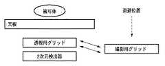
図1は、本発明の第1の実施形態に係る放射線画像撮影システムの構成を示すブロック図である。図1に示すように、本実施形態に係る放射線画像撮影システムは、被写体101に放射線(X線)を照射するX線部102と、透視用グリッド103と撮影用グリッド104とを切り替えるグリッド切替部105と、グリッドを介してX線を検出する2次元検出部106と、2次元検出部106で検出されたX線を光学像(画像)に変換する読み取り制御部107と、画像を記憶するメモリ部108と、透視用グリッド103又は撮影用グリッド104による画像上のグリッド縞を低減するグリッド縞低減部109を備える画像処理部110と、画像を表示する表示部111と、上記各部を制御するシステム制御部112と、操作者が本放射線画像撮影システムを操作・設定等するためのユーザインタフェース部113とから構成される。
【0017】
本実施形態におけるシステム制御部112は、透視や撮影で要求される事項を換算して、X線条件、グリッド条件及び読み取り条件を決定する。尚、これらの撮影条件は、単に透視と撮影とに二分されるわけではなく、透視や撮影においてもさらに患者の撮影部位によって細かく分類されるべきものである。本実施形態では、このような細部にまで分類されたデータ収集モード(透視モードや撮影モード或いはそれらの程度が異なるモード)を、操作者がユーザインタフェース部113を用いて設定する。このため、ユーザインタフェース部113には、操作者による様々な画像の種類等に対する詳細な要求に応じられるように複数種類の撮影ボタン等が備わっている。
【0018】
図2は、透視及び撮影の場合におけるX線、グリッド及び読み取り条件の一例を示す図である。本実施形態では、図2に示すような条件がシステム制御部112内のメモリ等に記憶されることにより、操作者によるユーザインタフェース部3からの撮影条件等の設定を簡単化することが可能となる。すなわち、ユーザインタフェース部113で設定された透視モード或いは撮影モードに応じて、図2に示すようなX線条件、グリッド条件、又は読み取り条件に関するデータが読み込まれて、それぞれX線部102、グリッド切替部105又は読み取り制御部104がコントロールされる。
【0019】
図3は、本実施形態に係る放射線画像撮影システムにおけるシステム制御の流れを説明するためのフローチャートである。上述したように、操作者は、まず撮影モードの設定(変更)をユーザインタフェース部113を介して行う(ステップS301)。これにより画素ピッチが変更される(ステップS302)。すなわち、図2に示すように、透視モードが設定された場合は読み取り画像ピッチは「大」に設定されるが、撮影モードが設定された場合は読み取り画像ピッチは「小」に設定される。
【0020】
すなわち、本実施形態に係る放射線画像撮影システムにおいて、読み取り制御部107は、2次元検出器106により検出されたX線から、上記読み取り条件に基づいて読み取り画素ピッチを変更して被写体の画像を取得することを特徴とする。
【0021】
次いで、設定されたモードに対応したグリッドが選択され(ステップS303)、グリッド切替部105によって透視用グリッド103又は撮影用グリッド104に切り替えられる(ステップS304)。すなわち、本実施形態に係る放射線画像撮影システムにおいて、グリッド切替部105が、被写体の透視時には透視用グリッド103を選択し、被写体の撮影時には撮影用グリッド104を選択することを特徴とする。
【0022】
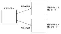
図4は、本発明の第1の実施形態におけるグリッド切替部105によるグリッド切り替えを説明するための概念図である。すなわち、「透視」の際は、X線条件が低電圧かつ低電流での撮影になるので、被写体101からの散乱線も少なく、また、撮影のための被写体101のポジショニングに意味があるので、収集される画像の空間分解能や周波数分解能も比較的低く要求される。例えば、透視用グリッド格子比として4:1のものを使用する。一方、「撮影」の際には、撮影された画像が医師の診断に供されるために、SNが良い画像が要求されるので管電流は高くなる。尚、管電圧は被写体(人体)のどの部位を撮影するかに依存する。例えば、胸部の撮影の際は、透視及び腹部の撮影の際よりも高い管電圧で撮影される。また、管電圧や管電流に依存して被写体101からの散乱線が多くなり、組織の画素値コントラストが高いことが要求されるので、グリッドは格子比の高いものが選択される。例えば、撮影用グリッド格子比として10:1のものを使用する。
【0023】
また、図5は、本発明の第1の実施形態におけるグリッド切替部105によるグリッド切り替えの様子を説明するためのシステムブロック図である。図5に示すように、データ収集モードの切り替えに対応して、撮影用グリッド及び透視用グリッドがそれぞれ検出器と被写体の間に挿入される。一方、使用されないグリッドは退避位置に停止させられる。
【0024】
グリッドが切り替えられた後、被写体101に対してX線部102からX線を照射して透視又は撮影が行われ、上述したように被写体に関する画像が得られる。その後、グリッド縞低減部109によって、画像上に存在するグリッド縞の低減処理を行うために、グリッド低減処理パラメータが変更される(ステップS305)。そして、グリッド縞低減部109によって画像上に存在するグリッド縞の低減処理が行われる(ステップS306)。
【0025】
すなわち、本実施形態に係る放射線画像撮影システムは、被写体に対して放射線(X線)を照射するX線部102と、被写体を透過した放射線をグリッドを介して検出する2次元検出器106と、検出されたX線から被写体の画像を取得する読み取り制御部107とを備え、さらに、撮影条件(例えば、グリッド条件)を設定可能なユーザインタフェース113と、設定されたグリッド条件に基づいて複数のグリッドから一のグリッドを選択するグリッド切替部105と、グリッドによって生じる画像上のグリッド縞を低減するグリッド縞低減部109とを備えることを特徴とする。
【0026】
また、上記放射線画像撮影システムにおいては、上記撮影条件が、X線条件を含んでおり、X線部102が、当該放射線条件に基づいて、被写体に対して放射線を照射することを特徴とする。
【0027】
さらに、上記放射線画像撮影システムにおいては、上記撮影条件が、読み取り条件を含んでおり、読み取り制御部107が、当該読み取り条件に基づいて、検出された放射線から被写体の画像を取得することを特徴とする。
【0028】
ここで、透視モード又は撮影モードにおいて得られた画像中に存在するグリッド縞と、これを低減ためのグリッド縞低減処理に関して説明する。
【0029】
本実施形態では、上述のように、グリッドは揺動することなく固定グリッドシステムを採用している。その理由として、前述したように揺動システムは、機構の巨大化、温度上昇、ノイズ源等の要因になるとともに、透視の際の収集周期及び撮影時間に依存して揺動スピードを変更する必要があるためである。固定グリッドシステムを採用することによって、これらの問題が解消する。
【0030】
尚、本実施形態におけるグリッド縞低減処理は、固定グリッドシステムだけに限定されるものではなく、揺動グリッドシステムを採用した場合であっても、以下に述べるようなグリッド縞低減処理を行うことによって、揺動スピードと上記条件のミスマッチによりグリッドが画像中に発生してしまった際のグリッド縞低減に有効である。
【0031】
本実施形態におけるグリッド縞低減処理としてはさまざまな方法を用いることが可能である。例えば、2次元センサの画像ピッチFsから計算されるナイキスト周波数Fnq(=Fs/2)より低い周波数のグリッドを使用して、ローパスフィルタにより低減する方法を用いることができる(特許第2507659号)。この方法による場合は、透視画像と撮影画像では2次元センサの画像ピッチFsが異なるので、単純にはこれに対応してローパスフィルタの形状を変更することになるが、画像ピッチFsに起因して使用できるグリッド周波数も変化する。
【0032】
例えば、撮影時の画素のサンプルピッチがFs、この時にローパスフィルタ法で使用できるグリッド周波数をFg、透視時の画素のサンプルピッチがFs/2とすると、透視時に使用できるグリッドの周波数Fgも半分程度にする必要がある。具体的には、透視時に使用できるグリッドの周波数は、透視時のナイキスト周波数以下である必要がある。すなわち、データ収集モードに依存して、画素ピッチが変更になると使用できるグリッドの周波数が変更になり、それによって生じる画像中のグリッド周波数も変わってくるので、このグリッド縞を除去する縞低減処理のパラメータ(例えば、ローパスフィルタのカットオフ周波数)が変更になる。すなわち、本実施形態に係る放射線画像撮影システムでは、透視用グリッド103と撮影用グリッド104とは、格子比又はグリッド周波数が互いに異なることを特徴とする。
【0033】
また、グリッド低減処理の別の方法としては、グリッドに起因する縞構造を検出して、その縞構造を予測して除去する方法がある。この場合は、上述したローパスフィルタによる場合とは異なり、画素ピッチのナイキスト周波数よりも高い周波数のグリッドを使用する。さらに、この場合のモアレの基本周波数と第二高調波が同一の周波数になるようにグリッド周波数を選択する。この手法を用いる場合も、データ収集モードに依存して、画素ピッチが変更になると使用できるグリッドの周波数が変更になり、それによって生じる画像中のグリッド周波数も変わってくるので、このグリッド縞を除去する縞低減処理のパラメータ(例えば、画像中から検索するモアレの周波数)が変更になる。
【0034】
すなわち、本実施形態に係る放射線画像撮影システムでは、ユーザインタフェース112により設定された撮影条件に基づいて読み取り画素ピッチが変更した場合、グリッド切替部105は、変更した読み取り画素ピッチに対応したグリッド周波数を有するグリッドを選択することを特徴とする。
【0035】
上述したように,本実施形態によれば、同一の半導体センサ(FPD)を使用して透視又は撮影を行う場合、X線条件やセンサの読み取り画素ピッチ等が変化することに対応して、自動的に好適なグリッドが選択される。そして、選択された好適なグリッドが自動的に被写体101と2次元検出器106の間に挿入されて、最適の撮影条件での透視及び撮影が可能となる。
【0036】
また、従来は同一の半導体センサを透視と撮影両方に使用することは、透視時の小線量が問題で難しかったが、本実施形態では、透視時は画素ピッチを粗くして画像のSNを上げ、かつグリッドを低格子比、低周波数とすることによってグリッド透過線量を増加させることにより実現を可能とした。また、このときのシステムの機構を簡単化するために固定グリッドシステムを使用する場合、使用したグリッドに応じて最適なグリッド低減処理のパラメータを設定することによって、グリッド縞の影響の小さい画像を得ることが可能となった。
【0037】
<第2の実施形態>
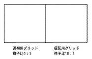
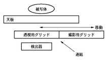
図6は、本発明の第2の実施形態におけるグリッド切替部によるグリッド切り替えを説明するための概念図である。また、図7は、本発明の第2の実施形態におけるグリッド切替部によるグリッド切り替えの様子を説明するためのシステムブロック図である。本実施形態における放射線画像撮影システムの構成及び動作は、基本的には上述した第1の実施形態と同一であるが、透視用及び撮影用グリッドが図6及び図7に示すように同一平面内に連結されて構成されている部分が異なっている。従って、本実施形態におけるグリッド切替部は、データ収集モードの切替えに対応して、撮影用及び透視用グリッドをそれぞれシフトすることによって、グリッド特性の変更を実現する。
【0038】
すなわち、本実施形態に係る放射線画像撮影システムにおいては、透視用グリッドと撮影用グリッドとは、同一平面内に連結されており、グリッド切替部は、当該透視用グリッドと当該撮影用グリッドとをシフトすることによっていずれかに切り替えることを特徴とする。これによって、同一平面内に連結されている透視用グリッドと撮影用グリッドに対しては、一方のグリッドの挿入により自動的に他方のグリッドの退避が行われる。
【0039】
本実施形態のメリットとしては、第1の実施形態の場合と比較して、透視及び撮影の時のグリッドの切替をシフトにより行うことで構造がより容易になり、また省スペースで高速に切替えることが可能である。また、透視から撮影の切替時間を短縮することも可能になる。さらに、グリッドが固定ではない場合でなく揺動させる場合であっても有利である。
【0040】
<第3の実施形態>
上述した第1及び第2の実施形態では、データ収集モードを透視と撮影という観点で分類したが、それ以外にも例えばデータ収集モードの画素ピッチに依存してシステムの制御を行うことも考えられる。すなわち、ユーザインタフェ−ス部を用いた操作者の選択により画素ピッチが決定されると、前述したようにグリッド低減処理を考慮して適切なグリッド(すなわち、グリッド周波数)が決定される。このように、収集画素ピッチの変更にあわせてグリッドが選択変更される機構の実現も可能である。
すなわち、本実施形態に係る放射線画像撮影システムは、被写体に対してX線を照射するX線部と、被写体を透過したX線をグリッドを介して検出する2次元検出器と、検出されたX線から被写体の画像を取得する画像読み取り制御部とを備え、さらに、データ収集モードを設定するユーザインタフェースと、データ収集モードに基づくグリッドを選択するグリッド切替部と、グリッドによって生じる画像上のグリッド縞を低減するグリッド縞低減部とを備えることを特徴とする。また、上記放射線画像撮影システムにおいて、上記ユーザインタフェースにより、2次元検出器により検出されたX線から被写体の画像を取得する際の画素ピッチを設定し、グリッド切替部が、設定された画素ピッチで取得された画像上のグリッド縞を低減するグリッド周波数を有するグリッドを選択することを特徴とする。
【0041】
尚、本発明は、複数の機器(例えば、ホストコンピュータ、インタフェース機器、リーダ、プリンタ等)から構成されるシステムに適用しても、一つの機器からなる装置(例えば、複写機、ファクシミリ装置等)に適用してもよい。
【0042】
また、本発明の目的は、前述した実施形態の機能を実現するソフトウェアのプログラムコードを記録した記録媒体(または記憶媒体)を、システムあるいは装置に供給し、そのシステムあるいは装置のコンピュータ(またはCPUやMPU)が記録媒体に格納されたプログラムコードを読み出し実行することによっても、達成されることは言うまでもない。この場合、記録媒体から読み出されたプログラムコード自体が前述した実施形態の機能を実現することになり、そのプログラムコードを記録した記録媒体は本発明を構成することになる。また、コンピュータが読み出したプログラムコードを実行することにより、前述した実施形態の機能が実現されるだけでなく、そのプログラムコードの指示に基づき、コンピュータ上で稼働しているオペレーティングシステム(OS)などが実際の処理の一部または全部を行い、その処理によって前述した実施形態の機能が実現される場合も含まれることは言うまでもない。
【0043】
さらに、記録媒体から読み出されたプログラムコードが、コンピュータに挿入された機能拡張カードやコンピュータに接続された機能拡張ユニットに備わるメモリに書き込まれた後、そのプログラムコードの指示に基づき、その機能拡張カードや機能拡張ユニットに備わるCPUなどが実際の処理の一部または全部を行い、その処理によって前述した実施形態の機能が実現される場合も含まれることは言うまでもない。
【0044】
本発明を上記記録媒体に適用する場合、その記録媒体には、先に説明したフローチャートに対応するプログラムコードが格納されることになる。
【0045】
【発明の効果】
以上説明したように、本発明によれば、撮影時又は透視時のグリッドを好適に設定し、最適の撮影条件で被検体の透視及び撮影をすることができる。
【図面の簡単な説明】
【図1】本発明の第1の実施形態に係る放射線画像撮影システムの構成を示すブロック図である。
【図2】透視及び撮影の場合におけるX線、グリッド及び読み取り条件の一例を示す図である。
【図3】本実施形態に係る放射線画像撮影システムにおけるシステム制御の流れを説明するためのフローチャートである。
【図4】本発明の第1の実施形態におけるグリッド切替部105によるグリッド切り替えを説明するための概念図である。
【図5】本発明の第1の実施形態におけるグリッド切替部105によるグリッド切り替えの様子を説明するためのシステムブロック図である。
【図6】本発明の第2の実施形態におけるグリッド切替部によるグリッド切り替えを説明するための概念図である。
【図7】本発明の第2の実施形態におけるグリッド切替部によるグリッド切り替えの様子を説明するためのシステムブロック図である。
【符号の説明】
101 被写体
102 X線部
103 透視用グリッド
104 撮影用グリッド
105 グリッド切替部
106 2次元検出器
107 読み取り制御部
108 メモリ部
109 グリッド縞低減部
110 画像処理部
111 表示部
112 システム制御部
113 ユーザインタフェース[0001]
BACKGROUND OF THE INVENTION
The present invention relates to a radiographic imaging technique for switching a grid between fluoroscopy and imaging.
[0002]
[Prior art]
Conventionally, as a technique of using different grids for fluoroscopy apparatus (when shooting a moving image) and when shooting (when shooting a still image), a grid moving mechanism of an X-ray imaging fluoroscopic table (see, for example, Patent Document 1). A cassette telescopic X-ray imaging apparatus (for example, see Patent Document 2), an X-ray fluoroscopic imaging apparatus (for example, see Patent Document 3), and the like are known.
[0003]
The above-mentioned Patent Document 1 is a technology related to a faraway grid system, which is a reciprocating rocking mechanism capable of transmitting a rocking force to a grid incorporated in a high-speed imaging apparatus that performs X-ray imaging, and an X-ray imaging region of the grid. A retraction mechanism capable of retraction drive and carry-in drive; and a connection mechanism capable of connecting and releasing the grid and the reciprocating rocking mechanism. A grid moving mechanism for an X-ray imaging fluoroscopic table is disclosed, which is connected and released from the reciprocating rocking mechanism when the grid is retracted.
[0004]
According to the description of Patent Document 1, continuous shooting (rapid shooting) is possible when a single film is divided and shot, but in this case, the grid is used by utilizing the elasticity of a spring as in the conventional grid mechanism. In the method of rocking the grid, the grid rocking motion gradually attenuates over time, so stripes often remain on the divided photos during continuous shooting, which cannot be completely removed. There was a problem. Therefore, in Patent Document 1, a grid moving mechanism of an X-ray fluoroscopic imaging table that does not cause stripes on divided photographs even in continuous imaging and can be retreated from the X-ray imaging area when the grid is not used. Is disclosed.
[0005]
In Patent Document 2, a grid that removes scattered X-rays from a subject that has been exposed to X-rays from an X-ray source, and the grid and a film are interposed between the grid and the subject and transmitted through the subject. A detector that detects X-rays and outputs a detection signal to an X-ray controller that controls the X-ray dose; a contact plate that includes a lead plate that removes backscattered X-rays on the back surface; A fluoroscopic grid provided on the front of an image intensifier that converts a line into an optical image and removes scattered X-rays; a mechanism that opens and closes the contact plate and contacts the film; A mechanism for transporting the contact plate from the film delivery position to the photographing position, the fluoroscopic position, and the park position, and returning the film to the film delivery position after completion of the fluoroscopic photographing, and the grid and detector adapted from the contact plate at the time of photographing. Replacement, the perspective and exchange control mechanism in the grid, the cassette-less X-ray fluoroscopic imaging apparatus characterized by comprising a discloses fit during fluoroscopy.
[0006]
According to the description of Patent Document 2, in order to stabilize the density at the time of photographing, the contact plate that jumps in at the time of photographing has a grid, a film, and a detector (phototimer) for stabilizing the density. It is integrated. Patent Document 2 discloses that the grid is changed during fluoroscopy and shooting, and that the grid is changed depending on shooting conditions such as tube voltage during the same fluoroscopy. .
[0007]
Furthermore, in Patent Document 3, the fluoroscopic mode and the radiographing mode can be set, and the image intensifier and the fluoroscopy grid are fixedly arranged in the X-ray irradiation field in the normal state, and the radiographing mode is set. And an X-ray film contact holder and an imaging grid are arranged to jump into the X-ray irradiation field and the imaging grid is swung, a grid fixing frame for fixing the imaging grid; A grid swinging rail that moves the grid fixing frame between the standby position and the imaging position and that can be swung at the imaging position, and the X-ray film contact holder. The holder driving frame for moving between the X-ray film and the holder driving frame for moving the X-ray film adhesion holder. And the drive mechanism is driven between the grid fixing frame and the holder driving frame to move the holder driving frame between the standby position and the photographing position. And a driven mechanism for moving the grid fixing frame between the standby position and the photographing position along the grid swinging rail following the holder driving frame. A fluoroscopic imaging apparatus is disclosed.
[0008]
The technique described in Patent Document 3 is intended to link a rocking mechanism of a grid at the time of photographing and a jumping mechanism of a photographing frame (a film and an intensifying screen are in close contact). The grid is fixed on the entire surface of the fluoroscopic sensor (II).
[0009]
From the technical background described above, a radiographic imaging apparatus that uses a single FPD sensor (Flat Panel Detector) using a semiconductor and switches different grids during fluoroscopy and radiography can be considered.
[0010]
[Patent Document 1]
JP-A-61-220631 [Patent Document 2]
JP-A-2-191936 [Patent Document 3]
Japanese Patent Laid-Open No. 3-53238
[Problems to be solved by the invention]
However, in a radiographic imaging apparatus that performs both fluoroscopy and imaging using an FPD sensor that uses a semiconductor, the following matters are problematic. That is, (1) The imaging dose at the time of fluoroscopy is about 1 / 100th at the time of imaging and the dose is very small.
(2) In fluoroscopy and radiography, it is necessary to switch the grid appropriately because the tube voltage is different in addition to the X-ray dose.
(3) When a grid is inserted, if it is a fixed grid, moire occurs in the image depending on the grid frequency and the sampling pitch of the FDP sensor.
(4) When the grid is swung, the mechanism becomes complicated, and in particular, the setting for optimizing the relationship between the image capture frequency and the grid swing period, and the photographing time and the swing speed becomes complicated.
[0012]
The present invention has been made in view of such circumstances, and radiographic imaging capable of suitably setting a grid during imaging or fluoroscopy and performing fluoroscopy and imaging of a subject under optimal imaging conditions. An object is to provide an apparatus.
[0013]
[Means for Solving the Problems]
In order to solve the above problems, a radiographic imaging apparatus according to the present invention is
A selection means for selecting one shooting condition from a plurality of shooting conditions with different pixel pitches read from the detector;
A grid portion in which a plurality of grids for absorbing scattered radiation from a subjectare connected in the same plane;
Grid selection means for selecting a grid having a grid frequency higher than the Nyquist frequency of the reading pixel pitch of the imaging condition selected by the selection means from theplurality of grids by moving the grid portion in the plane ;
A two-dimensional detector for converting radiation into an electrical signal and acquiring an image through the selected grid;
Grid stripe reduction means for performing grid stripe reduction processing corresponding to the grid frequency of the selected grid on grid stripes on the image generated by the selected grid.
[0015]
DETAILED DESCRIPTION OF THE INVENTION
Hereinafter, embodiments of the present invention will be described in detail with reference to the drawings.
[0016]
<First Embodiment>
FIG. 1 is a block diagram showing a configuration of a radiographic imaging system according to the first embodiment of the present invention. As shown in FIG. 1, the radiographic imaging system according to the present embodiment includes an
[0017]
The
[0018]
FIG. 2 is a diagram illustrating an example of X-rays, grids, and reading conditions in the case of fluoroscopy and imaging. In the present embodiment, the conditions as shown in FIG. 2 are stored in the memory or the like in the
[0019]
FIG. 3 is a flowchart for explaining the flow of system control in the radiographic imaging system according to the present embodiment. As described above, the operator first sets (changes) the shooting mode via the user interface unit 113 (step S301). Thereby, the pixel pitch is changed (step S302). That is, as shown in FIG. 2, when the fluoroscopic mode is set, the read image pitch is set to “large”, but when the shooting mode is set, the read image pitch is set to “small”.
[0020]
That is, in the radiographic imaging system according to the present embodiment, the
[0021]
Next, a grid corresponding to the set mode is selected (step S303), and the
[0022]
FIG. 4 is a conceptual diagram for explaining grid switching by the
[0023]
FIG. 5 is a system block diagram for explaining a state of grid switching by the
[0024]
After the grid is switched, the subject 101 is irradiated with X-rays from the
[0025]
That is, the radiographic imaging system according to the present embodiment includes an
[0026]
In the radiographic imaging system, the imaging condition includes an X-ray condition, and the
[0027]
Furthermore, in the radiographic imaging system, the imaging condition includes a reading condition, and the
[0028]
Here, the grid stripes present in the image obtained in the fluoroscopic mode or the photographing mode and the grid stripe reduction processing for reducing this will be described.
[0029]
In the present embodiment, as described above, the grid employs a fixed grid system without swinging. The reason for this is that, as described above, the rocking system causes the mechanism to become large, the temperature rises, the noise source, and the like, and the rocking speed needs to be changed depending on the collection period and photographing time during fluoroscopy. Because there is. Adopting a fixed grid system eliminates these problems.
[0030]
Note that the grid stripe reduction process in the present embodiment is not limited to a fixed grid system, and even when a swing grid system is employed, the grid stripe reduction process described below is performed. This is effective in reducing grid stripes when a grid is generated in an image due to a mismatch between the rocking speed and the above conditions.
[0031]
Various methods can be used as the grid stripe reduction processing in the present embodiment. For example, a method of reducing by a low-pass filter using a grid having a frequency lower than the Nyquist frequency Fnq (= Fs / 2) calculated from the image pitch Fs of the two-dimensional sensor can be used (Japanese Patent No. 2507659). In the case of this method, since the image pitch Fs of the two-dimensional sensor is different between the fluoroscopic image and the captured image, the shape of the low-pass filter is simply changed corresponding to this, but due to the image pitch Fs. The usable grid frequency also changes.
[0032]
For example, if the sample pitch of the pixel at the time of photographing is Fs, the grid frequency that can be used by the low-pass filter method at this time is Fg, and the sample pitch of the pixel at the time of fluoroscopy is Fs / 2, the frequency Fg of the grid that can be used at the time of fluoroscopy is about half. It is necessary to. Specifically, the frequency of the grid that can be used during fluoroscopy needs to be equal to or lower than the Nyquist frequency during fluoroscopy. That is, depending on the data acquisition mode, the frequency of the grid that can be used is changed when the pixel pitch is changed, and the grid frequency in the resulting image also changes. A parameter (for example, a cutoff frequency of a low-pass filter) is changed. That is, the radiographic imaging system according to the present embodiment is characterized in that the perspective grid 103 and the
[0033]
As another method of the grid reduction process, there is a method of detecting a fringe structure caused by the grid and predicting and removing the fringe structure. In this case, unlike the case of using the low-pass filter described above, a grid having a frequency higher than the Nyquist frequency of the pixel pitch is used. Furthermore, the grid frequency is selected so that the fundamental frequency of the moire and the second harmonic in this case become the same frequency. Even when this method is used, depending on the data acquisition mode, the frequency of the grid that can be used is changed when the pixel pitch is changed, and the grid frequency in the resulting image also changes. The fringe reduction process parameter (for example, the frequency of the moire searched from the image) is changed.
[0034]
That is, in the radiographic imaging system according to the present embodiment, when the reading pixel pitch is changed based on the imaging conditions set by the
[0035]
As described above, according to the present embodiment, when fluoroscopy or imaging is performed using the same semiconductor sensor (FPD), the X-ray condition, the read pixel pitch of the sensor, and the like are automatically changed. A suitable grid is selected. Then, the selected suitable grid is automatically inserted between the subject 101 and the two-
[0036]
Conventionally, using the same semiconductor sensor for both fluoroscopy and radiography has been difficult due to the small dose during fluoroscopy, but in this embodiment, the pixel pitch is increased during fluoroscopy to increase the SN of the image. In addition, the grid can be realized by increasing the grid penetration dose by setting the grid to a low grid ratio and a low frequency. In addition, when a fixed grid system is used to simplify the system mechanism at this time, an image with less influence of grid stripes is obtained by setting optimal grid reduction processing parameters according to the grid used. It became possible.
[0037]
<Second Embodiment>
FIG. 6 is a conceptual diagram for explaining grid switching by the grid switching unit in the second embodiment of the present invention. FIG. 7 is a system block diagram for explaining a state of grid switching by the grid switching unit in the second embodiment of the present invention. The configuration and operation of the radiographic image capturing system in this embodiment are basically the same as those in the first embodiment described above, but the fluoroscopic and imaging grids are in the same plane as shown in FIGS. The parts connected to each other are different. Accordingly, the grid switching unit according to the present embodiment realizes the change of the grid characteristics by shifting the photographing grid and the perspective grid in response to the switching of the data collection mode.
[0038]
That is, in the radiographic imaging system according to the present embodiment, the fluoroscopic grid and the radiographic grid are connected in the same plane, and the grid switching unit shifts the fluoroscopic grid and the radiographic grid. It is characterized by switching to either. Thus, with respect to the perspective grid and the imaging grid connected in the same plane, the other grid is automatically retracted by inserting one grid.
[0039]
As an advantage of this embodiment, compared to the case of the first embodiment, the structure is made easier by switching the grid at the time of fluoroscopy and photographing, and the structure can be switched at high speed in a small space. Is possible. In addition, it is possible to shorten the switching time for photographing from fluoroscopy. Furthermore, it is advantageous even when the grid is not fixed but rocked.
[0040]
<Third Embodiment>
In the first and second embodiments described above, the data collection modes are classified from the viewpoints of fluoroscopy and photographing. However, it is also possible to control the system depending on, for example, the pixel pitch of the data collection mode. . That is, when the pixel pitch is determined by the operator's selection using the user interface unit, an appropriate grid (that is, grid frequency) is determined in consideration of the grid reduction processing as described above. As described above, it is possible to realize a mechanism in which the grid is selectively changed in accordance with the change of the collection pixel pitch.
That is, the radiographic imaging system according to this embodiment includes an X-ray unit that irradiates an object with X-rays, a two-dimensional detector that detects X-rays transmitted through the object through a grid, and detected X-rays. An image reading control unit that acquires an image of a subject from a line, a user interface that sets a data acquisition mode, a grid switching unit that selects a grid based on the data acquisition mode, and grid stripes on an image generated by the grid And a grid stripe reduction unit for reducing the above. In the radiographic imaging system, the user interface sets a pixel pitch for acquiring an image of a subject from an X-ray detected by a two-dimensional detector, and the grid switching unit sets the pixel pitch at the set pixel pitch. A grid having a grid frequency that reduces grid stripes on the acquired image is selected.
[0041]
Note that the present invention can be applied to a system composed of a plurality of devices (for example, a host computer, an interface device, a reader, a printer, etc.), but a device (for example, a copier, a facsimile machine, etc.) composed of a single device. You may apply to.
[0042]
Also, an object of the present invention is to supply a recording medium (or storage medium) in which a program code of software that realizes the functions of the above-described embodiments is recorded to a system or apparatus, and the computer (or CPU or Needless to say, this can also be achieved when the MPU) reads and executes the program code stored in the recording medium. In this case, the program code itself read from the recording medium realizes the functions of the above-described embodiment, and the recording medium on which the program code is recorded constitutes the present invention. Further, by executing the program code read by the computer, not only the functions of the above-described embodiments are realized, but also an operating system (OS) running on the computer based on the instruction of the program code. It goes without saying that a case where the function of the above-described embodiment is realized by performing part or all of the actual processing and the processing is included.
[0043]
Further, after the program code read from the recording medium is written in a memory provided in a function expansion card inserted into the computer or a function expansion unit connected to the computer, the function expansion is performed based on the instruction of the program code. It goes without saying that the CPU or the like provided in the card or the function expansion unit performs part or all of the actual processing, and the functions of the above-described embodiments are realized by the processing.
[0044]
When the present invention is applied to the recording medium, program code corresponding to the flowchart described above is stored in the recording medium.
[0045]
【The invention's effect】
As described above, according to the present invention, it is possible to suitably set a grid at the time of imaging or fluoroscopy, and to perform fluoroscopy and imaging of the subject under optimal imaging conditions.
[Brief description of the drawings]
FIG. 1 is a block diagram showing a configuration of a radiographic image capturing system according to a first embodiment of the present invention.
FIG. 2 is a diagram illustrating an example of X-rays, grids, and reading conditions in the case of fluoroscopy and imaging.
FIG. 3 is a flowchart for explaining the flow of system control in the radiographic imaging system according to the present embodiment.
FIG. 4 is a conceptual diagram for explaining grid switching by the
FIG. 5 is a system block diagram for explaining a state of grid switching by the
FIG. 6 is a conceptual diagram for explaining grid switching by a grid switching unit according to a second embodiment of the present invention.
FIG. 7 is a system block diagram for explaining a state of grid switching by a grid switching unit in the second embodiment of the present invention.
[Explanation of symbols]
DESCRIPTION OF
Claims (4)
Translated fromJapanese被写体からの散乱放射線を吸収するための複数のグリッドが同一平面に連結されたグリッド部と、
前記グリッド部を前記平面内で移動させることにより、前記複数のグリッドから、前記選択手段で選択された撮影条件の読み取り画素ピッチのナイキスト周波数よりもグリッド周波数が高いグリッドを選択するグリッド選択手段と、
前記選択されたグリッドを介して、放射線を電気信号に変換し、画像を取得する2次元検出器と、
前記選択されたグリッドによって生じる前記画像上のグリッド縞に対して、前記選択されたグリッドのグリッド周波数に応じたグリッド縞低減処理を行うグリッド縞低減手段とを備えることを特徴とする放射線画像撮影装置。Selection means for selecting one imaging condition from a plurality of imaging conditions having different pixel pitches read from the detector;
A grid portion in which a plurality of grids for absorbing scattered radiation from a subjectare connected in the same plane;
Grid selection means for selecting a grid having a grid frequency higher than the Nyquist frequency of the reading pixel pitch of the imaging condition selected by the selection means from theplurality of grids by moving the grid portion in the plane ;
A two-dimensional detector for converting radiation into an electrical signal and acquiring an image through the selected grid;
A radiographic imaging apparatus comprising: a grid stripe reduction unit that performs a grid stripe reduction process according to a grid frequency of the selected grid on a grid stripe on the image generated by the selected grid. .
前記グリッド選択手段で選択されたグリッドの格子比に基づき、前記増幅器の増幅度を設定する設定手段とを有することを特徴とする請求項1に記載の放射線画像撮影装置。An amplifier for amplifying the electrical signal of the two-dimensional detector;
The radiographic imaging apparatus according to claim 1, further comprising a setting unit that sets an amplification degree of the amplifier based on a grid ratio of the grid selected by the grid selection unit.
前記複数の選択条件として、動画撮影と静止画撮影が含まれ、
動画撮影時における照射手段の管電圧は、静止画撮影時における管電圧より低いことを特徴とする請求項1に記載の放射線画像撮影装置。Having irradiation means for irradiating radiation toward the subject;
The plurality of selection conditions include moving image shooting and still image shooting,
The radiographic image capturing apparatus according to claim 1, wherein the tube voltage of the irradiation unit at the time of moving image shooting is lower than the tube voltage at the time of still image shooting.
Priority Applications (2)
| Application Number | Priority Date | Filing Date | Title |
|---|---|---|---|
| JP2003133532AJP4497837B2 (en) | 2003-05-12 | 2003-05-12 | Radiation imaging equipment |
| US10/844,982US7110502B2 (en) | 2003-05-12 | 2004-05-12 | Radiographic apparatus and method for switching a grid |
Applications Claiming Priority (1)
| Application Number | Priority Date | Filing Date | Title |
|---|---|---|---|
| JP2003133532AJP4497837B2 (en) | 2003-05-12 | 2003-05-12 | Radiation imaging equipment |
Publications (3)
| Publication Number | Publication Date |
|---|---|
| JP2004329783A JP2004329783A (en) | 2004-11-25 |
| JP2004329783A5 JP2004329783A5 (en) | 2006-06-22 |
| JP4497837B2true JP4497837B2 (en) | 2010-07-07 |
Family
ID=33410650
Family Applications (1)
| Application Number | Title | Priority Date | Filing Date |
|---|---|---|---|
| JP2003133532AExpired - Fee RelatedJP4497837B2 (en) | 2003-05-12 | 2003-05-12 | Radiation imaging equipment |
Country Status (2)
| Country | Link |
|---|---|
| US (1) | US7110502B2 (en) |
| JP (1) | JP4497837B2 (en) |
Families Citing this family (64)
| Publication number | Priority date | Publication date | Assignee | Title |
|---|---|---|---|---|
| US8571289B2 (en) | 2002-11-27 | 2013-10-29 | Hologic, Inc. | System and method for generating a 2D image from a tomosynthesis data set |
| US7577282B2 (en) | 2002-11-27 | 2009-08-18 | Hologic, Inc. | Image handling and display in X-ray mammography and tomosynthesis |
| US7616801B2 (en) | 2002-11-27 | 2009-11-10 | Hologic, Inc. | Image handling and display in x-ray mammography and tomosynthesis |
| US10638994B2 (en) | 2002-11-27 | 2020-05-05 | Hologic, Inc. | X-ray mammography with tomosynthesis |
| US8565372B2 (en) | 2003-11-26 | 2013-10-22 | Hologic, Inc | System and method for low dose tomosynthesis |
| US7123684B2 (en) | 2002-11-27 | 2006-10-17 | Hologic, Inc. | Full field mammography with tissue exposure control, tomosynthesis, and dynamic field of view processing |
| US7662082B2 (en) | 2004-11-05 | 2010-02-16 | Theragenics Corporation | Expandable brachytherapy device |
| US7702142B2 (en) | 2004-11-15 | 2010-04-20 | Hologic, Inc. | Matching geometry generation and display of mammograms and tomosynthesis images |
| EP1816965B1 (en) | 2004-11-26 | 2016-06-29 | Hologic, Inc. | Integrated multi-mode mammography/tomosynthesis x-ray system |
| JP4617214B2 (en)* | 2005-08-05 | 2011-01-19 | キヤノン株式会社 | Image photographing apparatus, control method therefor, program, and image photographing system |
| JP4773768B2 (en)* | 2005-08-16 | 2011-09-14 | キヤノン株式会社 | Radiation imaging apparatus, control method therefor, and radiation imaging system |
| US7465268B2 (en) | 2005-11-18 | 2008-12-16 | Senorx, Inc. | Methods for asymmetrical irradiation of a body cavity |
| WO2007095330A2 (en) | 2006-02-15 | 2007-08-23 | Hologic Inc | Breast biopsy and needle localization using tomosynthesis systems |
| US7630533B2 (en) | 2007-09-20 | 2009-12-08 | Hologic, Inc. | Breast tomosynthesis with display of highlighted suspected calcifications |
| US20100264324A1 (en)* | 2007-11-19 | 2010-10-21 | Koninklijke Philips Electronics N.V. | radiation detector comprising an imaging radiation-collimating structure |
| WO2009084104A1 (en)* | 2007-12-28 | 2009-07-09 | Shimadzu Corporation | X-ray equipment |
| JP2009226203A (en)* | 2008-02-28 | 2009-10-08 | Fujifilm Corp | Radiation image capturing system, radiation image capturing method, and program |
| US9248311B2 (en) | 2009-02-11 | 2016-02-02 | Hologic, Inc. | System and method for modifying a flexibility of a brachythereapy catheter |
| US9579524B2 (en) | 2009-02-11 | 2017-02-28 | Hologic, Inc. | Flexible multi-lumen brachytherapy device |
| JP5517484B2 (en)* | 2009-05-01 | 2014-06-11 | キヤノン株式会社 | Imaging apparatus and imaging system, control method thereof, and program thereof |
| US10207126B2 (en) | 2009-05-11 | 2019-02-19 | Cytyc Corporation | Lumen visualization and identification system for multi-lumen balloon catheter |
| ES2862525T3 (en) | 2009-10-08 | 2021-10-07 | Hologic Inc | Needle Breast Biopsy System and Method of Use |
| JP5407774B2 (en)* | 2009-11-10 | 2014-02-05 | 株式会社島津製作所 | Radiography equipment |
| US9352172B2 (en) | 2010-09-30 | 2016-05-31 | Hologic, Inc. | Using a guide member to facilitate brachytherapy device swap |
| CA2813591C (en) | 2010-10-05 | 2020-09-22 | Hologic, Inc. | Upright x-ray breast imaging with a ct mode, multiple tomosynthesis modes, and a mammography mode |
| US20120133600A1 (en) | 2010-11-26 | 2012-05-31 | Hologic, Inc. | User interface for medical image review workstation |
| US8746561B1 (en) | 2010-12-23 | 2014-06-10 | Sandia Corporation | Grid-based precision aim system and method for disrupting suspect objects |
| US10342992B2 (en) | 2011-01-06 | 2019-07-09 | Hologic, Inc. | Orienting a brachytherapy applicator |
| JP6057922B2 (en) | 2011-03-08 | 2017-01-11 | ホロジック, インコーポレイテッドHologic, Inc. | System and method for dual energy and / or contrast enhanced breast imaging for screening, diagnosis and biopsy |
| JP5672147B2 (en)* | 2011-05-24 | 2015-02-18 | コニカミノルタ株式会社 | Chest diagnosis support information generation system |
| EP2782505B1 (en) | 2011-11-27 | 2020-04-22 | Hologic, Inc. | System and method for generating a 2d image using mammography and/or tomosynthesis image data |
| JP6240097B2 (en) | 2012-02-13 | 2017-11-29 | ホロジック インコーポレイティッド | How to navigate a tomosynthesis stack using composite image data |
| JP2014018543A (en)* | 2012-07-23 | 2014-02-03 | Canon Inc | Radiation generating device and radiography system |
| US10092358B2 (en) | 2013-03-15 | 2018-10-09 | Hologic, Inc. | Tomosynthesis-guided biopsy apparatus and method |
| CN105451657A (en) | 2013-03-15 | 2016-03-30 | 霍罗吉克公司 | System and method for navigating tomosynthesis stack including automatic focusing |
| CA2925907C (en) | 2013-10-09 | 2022-03-15 | Hologic, Inc. | X-ray breast tomosynthesis enhancing spatial resolution including in the thickness direction of a flattened breast |
| EP3060132B1 (en) | 2013-10-24 | 2019-12-04 | Hologic, Inc. | System and method for navigating x-ray guided breast biopsy |
| JP6506769B2 (en) | 2014-02-28 | 2019-04-24 | ホロジック, インコーポレイテッドHologic, Inc. | System and method for generating and displaying tomosynthesis image slabs |
| JP6042855B2 (en) | 2014-03-28 | 2016-12-14 | 富士フイルム株式会社 | Radiation image capturing apparatus, radiation image capturing method, and radiation image capturing program |
| JP6105508B2 (en) | 2014-03-28 | 2017-03-29 | 富士フイルム株式会社 | Radiation image capturing apparatus, radiation image capturing method, and radiation image capturing program |
| EP3240483B1 (en) | 2015-12-18 | 2018-08-01 | Koninklijke Philips N.V. | Tomographic imaging device and method for sparse angular sampling |
| WO2017185028A1 (en) | 2016-04-22 | 2017-10-26 | Hologic, Inc. | Tomosynthesis with shifting focal spot x-ray system using an addressable array |
| EP3600047A1 (en) | 2017-03-30 | 2020-02-05 | Hologic, Inc. | System and method for hierarchical multi-level feature image synthesis and representation |
| EP3600052A1 (en) | 2017-03-30 | 2020-02-05 | Hologic, Inc. | System and method for targeted object enhancement to generate synthetic breast tissue images |
| CN110621233B (en) | 2017-03-30 | 2023-12-12 | 豪洛捷公司 | Method for processing breast tissue image data |
| WO2018236565A1 (en) | 2017-06-20 | 2018-12-27 | Hologic, Inc. | METHOD AND SYSTEM FOR MEDICAL IMAGING WITH DYNAMIC SELF-LEARNING |
| EP4129188A1 (en) | 2017-08-16 | 2023-02-08 | Hologic, Inc. | Techniques for breast imaging patient motion artifact compensation |
| EP3449835B1 (en) | 2017-08-22 | 2023-01-11 | Hologic, Inc. | Computed tomography system and method for imaging multiple anatomical targets |
| US11166692B2 (en)* | 2018-03-30 | 2021-11-09 | Shimadzu Corporation | X-ray image diagnostic apparatus |
| US11090017B2 (en) | 2018-09-13 | 2021-08-17 | Hologic, Inc. | Generating synthesized projection images for 3D breast tomosynthesis or multi-mode x-ray breast imaging |
| WO2020068851A1 (en) | 2018-09-24 | 2020-04-02 | Hologic, Inc. | Breast mapping and abnormality localization |
| WO2020068767A1 (en) | 2018-09-28 | 2020-04-02 | Hologic, Inc. | System and method for synthetic breast tissue image generation by high density element suppression |
| WO2020107019A1 (en) | 2018-11-25 | 2020-05-28 | Hologic, Inc. | Multimodality hanging protocols |
| DE202020006044U1 (en) | 2019-03-29 | 2024-07-02 | Hologic Inc. | Report generation for cropped digital images |
| WO2021034829A1 (en)* | 2019-08-22 | 2021-02-25 | John Bean Technologies Corporation | X-ray unit technology modules and automated application training |
| EP3832689A3 (en) | 2019-12-05 | 2021-08-11 | Hologic, Inc. | Systems and methods for improved x-ray tube life |
| US11471118B2 (en) | 2020-03-27 | 2022-10-18 | Hologic, Inc. | System and method for tracking x-ray tube focal spot position |
| US11786191B2 (en) | 2021-05-17 | 2023-10-17 | Hologic, Inc. | Contrast-enhanced tomosynthesis with a copper filter |
| EP4145117A1 (en)* | 2021-09-01 | 2023-03-08 | Malvern Panalytical B.V. | Adaptable x-ray analysis apparatus |
| US12186119B2 (en) | 2021-10-05 | 2025-01-07 | Hologic, Inc. | Interactive model interface for image selection in medical imaging systems |
| US12254586B2 (en) | 2021-10-25 | 2025-03-18 | Hologic, Inc. | Auto-focus tool for multimodality image review |
| WO2023097279A1 (en) | 2021-11-29 | 2023-06-01 | Hologic, Inc. | Systems and methods for correlating objects of interest |
| US12414217B2 (en) | 2022-02-07 | 2025-09-09 | Hologic, Inc. | Systems and methods for adaptively controlling filament current in an X-ray tube |
| JP2025129820A (en)* | 2024-02-26 | 2025-09-05 | 富士フイルム株式会社 | Radiography system, radiation photography method, and radiation photography program |
Family Cites Families (19)
| Publication number | Priority date | Publication date | Assignee | Title |
|---|---|---|---|---|
| US4099063A (en)* | 1976-11-10 | 1978-07-04 | General Electric Company | X-ray field defining masks for a spot film device |
| JPH0618571B2 (en)* | 1985-03-26 | 1994-03-16 | 株式会社東芝 | X-ray radiography table grid moving mechanism |
| JPH02191936A (en)* | 1989-01-20 | 1990-07-27 | Toshiba Corp | Cassette-less X-ray fluoroscopic imaging device |
| JPH02198265A (en)* | 1989-01-27 | 1990-08-06 | Toshiba Corp | image display device |
| JPH0353238A (en)* | 1989-07-21 | 1991-03-07 | Toshiba Corp | X-ray fluoro-radiographic apparatus |
| US5262871A (en)* | 1989-11-13 | 1993-11-16 | Rutgers, The State University | Multiple resolution image sensor |
| JP2507659B2 (en)* | 1990-04-04 | 1996-06-12 | 株式会社東芝 | Radiation image reader |
| JP2652113B2 (en) | 1992-10-12 | 1997-09-10 | 本田技研工業株式会社 | Sprocket manufacturing method |
| US5636259A (en)* | 1995-05-18 | 1997-06-03 | Continental X-Ray Corporation | Universal radiographic/fluoroscopic digital room |
| JPH1194532A (en)* | 1997-09-22 | 1999-04-09 | Toshiba Corp | X-ray solid state detector and X-ray diagnostic apparatus |
| JPH11128214A (en)* | 1997-10-30 | 1999-05-18 | Shimadzu Corp | X-ray diagnostic equipment |
| JP3554172B2 (en)* | 1998-01-09 | 2004-08-18 | キヤノン株式会社 | Radiography equipment |
| JPH11331703A (en)* | 1998-03-20 | 1999-11-30 | Toshiba Corp | Imaging device |
| US20010033638A1 (en)* | 2000-02-04 | 2001-10-25 | Hitoshi Inoue | Image acquisition method and apparatus |
| JP3884929B2 (en)* | 2001-08-01 | 2007-02-21 | キヤノン株式会社 | Radiation image acquisition apparatus and design method |
| JP4612754B2 (en)* | 2000-02-04 | 2011-01-12 | キヤノン株式会社 | Image acquisition apparatus and image acquisition method |
| JP4500400B2 (en)* | 2000-02-04 | 2010-07-14 | キヤノン株式会社 | Image acquisition apparatus and image acquisition method |
| JP2001249183A (en)* | 2000-03-06 | 2001-09-14 | Matsushita Electric Ind Co Ltd | X-ray equipment |
| JP2003008885A (en)* | 2001-06-19 | 2003-01-10 | Fuji Photo Film Co Ltd | Image reproduction system |
- 2003
- 2003-05-12JPJP2003133532Apatent/JP4497837B2/ennot_activeExpired - Fee Related
- 2004
- 2004-05-12USUS10/844,982patent/US7110502B2/ennot_activeExpired - Fee Related
Also Published As
| Publication number | Publication date |
|---|---|
| US20040228439A1 (en) | 2004-11-18 |
| US7110502B2 (en) | 2006-09-19 |
| JP2004329783A (en) | 2004-11-25 |
Similar Documents
| Publication | Publication Date | Title |
|---|---|---|
| JP4497837B2 (en) | Radiation imaging equipment | |
| JP5890598B2 (en) | Method for enhancing an image of a fluoroscopic image | |
| KR100830549B1 (en) | Dual irradiation mammography device and breast imaging method using the device | |
| JP5438424B2 (en) | Medical image photographing device and photographing method thereof | |
| JP4773309B2 (en) | Breast radiation image capturing apparatus and breast radiation image capturing method | |
| JP5123702B2 (en) | Radiation CT system | |
| JP6154021B2 (en) | Radiation image capturing apparatus, radiation image capturing method, and radiation image capturing program | |
| JP2000083951A (en) | X-ray imaging apparatus and grid apparatus | |
| JP2004000605A (en) | X-ray CT system | |
| JP2005013738A (en) | System and method for scanning object in tomosynthesis application | |
| JP6475138B2 (en) | Control device, radiographic image capturing device, radiographic image capturing method, and radiographic image capturing program | |
| JP3631215B2 (en) | Radiation image processing apparatus, radiation image processing system, radiation imaging system, radiation imaging apparatus, radiation image processing method, computer-readable storage medium, and program | |
| JP3658389B2 (en) | Radiography equipment | |
| JP2008125691A (en) | Radiation image calculation method, apparatus, and program | |
| JP6398685B2 (en) | Tomographic image generation system and image processing apparatus | |
| JP4999536B2 (en) | Radiation image processing apparatus, radiation dose control apparatus, and computer program | |
| JP5538734B2 (en) | Radiation imaging apparatus and processing method thereof | |
| JP4731704B2 (en) | Medical photographing system and photographing display method | |
| JP4559723B2 (en) | Radiation CT apparatus, image processing apparatus, and image processing method | |
| JP5274337B2 (en) | Radiation detection apparatus and method, and radiographic imaging system | |
| JP5523722B2 (en) | X-ray diagnostic imaging equipment | |
| JP2014023611A (en) | Radiographic apparatus, control method, and program | |
| CN110678124B (en) | Tomographic image generation method and radiographic apparatus | |
| JP2010227512A (en) | Radiation detection apparatus and method, and radiographic imaging system | |
| JP2005006886A (en) | Radiation imaging equipment |
Legal Events
| Date | Code | Title | Description |
|---|---|---|---|
| A521 | Request for written amendment filed | Free format text:JAPANESE INTERMEDIATE CODE: A523 Effective date:20060428 | |
| A621 | Written request for application examination | Free format text:JAPANESE INTERMEDIATE CODE: A621 Effective date:20060428 | |
| A977 | Report on retrieval | Free format text:JAPANESE INTERMEDIATE CODE: A971007 Effective date:20090414 | |
| A131 | Notification of reasons for refusal | Free format text:JAPANESE INTERMEDIATE CODE: A131 Effective date:20090427 | |
| A521 | Request for written amendment filed | Free format text:JAPANESE INTERMEDIATE CODE: A523 Effective date:20090626 | |
| A131 | Notification of reasons for refusal | Free format text:JAPANESE INTERMEDIATE CODE: A131 Effective date:20090907 | |
| A521 | Request for written amendment filed | Free format text:JAPANESE INTERMEDIATE CODE: A523 Effective date:20091106 | |
| TRDD | Decision of grant or rejection written | ||
| A01 | Written decision to grant a patent or to grant a registration (utility model) | Free format text:JAPANESE INTERMEDIATE CODE: A01 Effective date:20100412 | |
| A01 | Written decision to grant a patent or to grant a registration (utility model) | Free format text:JAPANESE INTERMEDIATE CODE: A01 | |
| A61 | First payment of annual fees (during grant procedure) | Free format text:JAPANESE INTERMEDIATE CODE: A61 Effective date:20100413 | |
| FPAY | Renewal fee payment (event date is renewal date of database) | Free format text:PAYMENT UNTIL: 20130423 Year of fee payment:3 | |
| R150 | Certificate of patent or registration of utility model | Free format text:JAPANESE INTERMEDIATE CODE: R150 | |
| FPAY | Renewal fee payment (event date is renewal date of database) | Free format text:PAYMENT UNTIL: 20130423 Year of fee payment:3 | |
| FPAY | Renewal fee payment (event date is renewal date of database) | Free format text:PAYMENT UNTIL: 20140423 Year of fee payment:4 | |
| LAPS | Cancellation because of no payment of annual fees |