JP4497603B2 - Tag device for search object management system, search object management system, and search object management method - Google Patents
Tag device for search object management system, search object management system, and search object management methodDownload PDFInfo
- Publication number
- JP4497603B2 JP4497603B2JP31515199AJP31515199AJP4497603B2JP 4497603 B2JP4497603 B2JP 4497603B2JP 31515199 AJP31515199 AJP 31515199AJP 31515199 AJP31515199 AJP 31515199AJP 4497603 B2JP4497603 B2JP 4497603B2
- Authority
- JP
- Japan
- Prior art keywords
- identification code
- tag
- signal
- unique identification
- tag device
- Prior art date
- Legal status (The legal status is an assumption and is not a legal conclusion. Google has not performed a legal analysis and makes no representation as to the accuracy of the status listed.)
- Expired - Fee Related
Links
Images


Landscapes
- Warehouses Or Storage Devices (AREA)
Description
Translated fromJapanese【0001】
【発明の属する技術分野】
この発明は、たとえばファイル等の被検索物を管理する被検索物管理システム用のタグ装置、被検索物管理システム、並びに被検索物管理方法に関する。
【0002】
【背景技術】
ファイル等を格納・管理する被検索物管理システムの一種として、それぞれに固有の識別符号を付与したタグ装置を各ファイルに取付けてからそれらのファイル格納棚に格納するようにしたものがある。
【0003】
この管理システムでは、各ファイルを格納棚に格納する際に、当該格納しようとするファイルに綴じられた書類名とそのファイルに割当てた識別符号とを、パソコン等を用いた管理システムの管理装置に登録してそれらを互いに関連づけた検索管理データを作成すると共に、その管理装置に接続された識別符号登録装置により当該割当てた識別符号を所定のタグ装置に書込んだ後、そのタグ装置をファイルに取付けて、そのファイルを格納棚に格納するようにしている。
【0004】
この管理システムでは、前記検索管理データに基づいて、ファイルに綴じられた書類名から容易にそのファイルに取付けられたタグ装置の識別番号を検索することができる。そして、例えば、格納棚に格納された各ファイルのタグ装置に向けて呼出用の識別符号を含む呼出信号を送信する一方で、それぞれのタグ装置側で、その呼出用の識別符号が自己の固有の識別符号と一致するか否かを判定させて、一致したときに該当するタグ装置側を発光させることにより、その発光を手掛りとして当該識別番号を有するタグ装置が取付けられたファイルを容易に検索することができる。
【0005】
図12は、このような管理システムに用いられるタグ装置の電気的構成を示す図である。
【0006】
このタグ装置は、赤外光信号を受信するための受信用光電素子101,この受信用光電素子101から出力された電気信号を増幅するためのアンプ102及びROM103aに格納されたソフトウエアプログラムに従って所定の動作を行うタグ制御部103とを備えており、前記管理装置側の登録装置より受信用光電素子101を通じてタグ制御部103に所定の識別符号の付与指令が与えられると、その識別符号をタグ制御部103のRAM103bに書込むように構成されている。
【0007】
また、上記タグ制御部103は、受信用光電素子101を通じて受信された呼出信号に含まれる識別符号と自己の識別符号とが一致するときには、発光ダイオード104を発光させるようになっている。
【0008】
また、このタグ装置は、受光により起電力を生じる光電素子105及びこの光電素子105の起電力により生じた電圧により充電がなされるコンデンサ等の充電素子106を備えており、この充電素子106を電源として、アンプ102やタグ制御部103の諸動作が行われるようになっている。
【0009】
【発明が解決しようとする課題】
ところで、上述のような被検索物管理システムでは、その管理装置側で割当てられた識別符号をタグ装置に書込む方式を採っているため、タグ装置側では、当該割当てられた識別符号をRAM103bに書換え自在に記憶できる構成を採っている。そして、そのように書込まれたデータをRAM103bに保持しておくために、そのRAM103bにデータ保持用の電源を供給している。
【0010】
しかしながら、上記タグ装置を長期間暗所に放置しておくと、光電素子105により充電がなされない状態で充電素子106の放電がすすみ、RAM103bに記憶内容の保持用の電源を供給し続けることができず、RAM103bに記憶させたデータが失われてしまうことになる。
【0011】
これは、電源としてボタン型一次電池等を用いた場合であっても、同様のことがいえる。
【0012】
このようになってしまうと、再度明所で光電素子105により充電素子106の充電を行っても、或いは、一次電池を交換しても、二度と上述したようなファイルの検索はできなくなってしまう。
【0013】
これを回避するためには、EEPROM等の書換可能な不揮発性メモリを、その書換回路と共に、タグ装置に搭載する手段等も考えられる。
【0014】
しかしながら、この場合には、その書換回路によって、電子部品の実装面積の増大に起因するタグ装置の大型化や製造コストの上昇、タグ装置動作中の消費電力増加を招くことになる。また、このようなタグ装置を用いてシステムを構成した場合、各タグ装置においてどのような識別符号が割当てられているかを管理するために、タグ装置に割当てられた識別符号を外部から見てわかるように印刷をするしたり、ラベルを貼付ける等の方法により表示する必要があった。
【0015】
そこで、この発明は上述したような各問題を解決すべくなされたもので、大型化や製造コストの上昇、消費電力増を招くことなく、被検索物の検索をより確実にすることが可能な被検索物管理システム用のタグ装置を提供すると共に、そのようなタグ装置の使用に適した被検索物管理システム、並びに被検索物管理方法を提供することを目的とする。
【0016】
【課題を解決するための手段】
上記の課題を解決するため、請求項1記載の発明は、格納棚に複数の被検索物が格納される被検索物管理システムにおいて、それぞれの被検索物にタグ装置が取付けられ、それら各タグ装置に割当てられた固有の識別符号を各被検索物の特定情報に関連づけて検索管理データを作成する被検索物管理システム用のタグ装置であって、識別符号返答指令信号を受信するタグ側受信手段と、固有の識別符号が含まれた返答信号を送信するタグ側送信手段と、固有の識別符号のデータを記憶した不揮発性読出専用記憶部を有し、前記受信手段を通じて識別符号返答指令信号を受信したときに、前記タグ側送信手段から前記固有の識別符号が含まれた信号を送信させるタグ制御部と、を備えたものである。
【0017】
また、呼出用の識別符号を含む呼出信号を受信する呼出用受信手段をさらに備え、前記タグ制御部が、その呼出用受信手段により受信された呼出信号に含まれる識別符号と自己の固有の識別符号とが一致するか否かを判定する機能をさらに備えさせ、前記タグ側送信手段として、可視光信号により返答信号を送信する可視光発光手段が用いられ、前記タグ制御部が、前記呼出信号に含まれる識別符号と自己の固有の識別符号と一致したと判定した際には、前記可視光発光手段を発光させることによりその一致した旨を外部に報知するようにしている。
【0018】
この場合に、請求項2のように、電源用の充電素子を充電する充電用光電素子をさらに備え、前記充電用光電素子と前記タグ側受信手段とが、同一面側に設けられているようにしてもよい。
【0019】
さらに、請求項3記載の発明は、格納棚に複数の被検索物が格納される被検索物管理システムにおいて、それぞれの被検索物にタグ装置を取付けて、各タグ装置に割当てられた固有の識別符号を各被検索物の特定情報に関連づけて管理データを作成する被検索物管理システムであって、識別符号返答指令信号を受信するタグ側受信手段と、固有の識別符号が含まれた返答信号を送信するタグ側送信手段と、固有の識別符号のデータを記憶した不揮発性読出専用記憶部を有し前記受信手段を通じて識別符号返答指令信号を受信したときに、前記タグ側送信手段から前記固有の識別符号が含まれた信号を送信させるタグ制御部と、を有するタグ装置と、タグ装置に識別符号返答指令信号を送信する管理装置側送信手段と、タグ装置から送信された返答信号を受信する管理装置側受信手段と、被検索物の特定情報の入力により、前記管理側送信手段から識別符号返答指令信号を送信させる一方、これに応答したタグ装置からの返答信号が前記管理側受信手段を通じて受信されると、その返答信号に含まれる識別符号を被検索物の特定情報と関連づけて管理データを作成する管理制御部とを有する管理装置と、を備え、前記タグ装置が、呼出用の識別符号を含む呼出信号を受信する呼出用受信手段をさらに備え、前記タグ制御部が、その呼出用受信手段により受信された呼出信号に含まれる識別符号と自己の固有の識別符号とが一致するか否かを判定する機能をさらに備えており、前記タグ側送信手段として、可視光信号により返答信号を送信する可視光発光手段が用いられ、前記タグ制御部が、前記呼出信号に含まれる識別符号と自己の固有の識別符号と一致したと判定した際には、前記可視光発光手段を発光させることによりその一致した旨を外部に報知するものである。
【0020】
また、請求項4記載の発明は、格納棚に複数の被検索物が格納され、それぞれの被検索物にタグ装置を取付けて、各タグ装置に割当てられた固有の識別符号を各被検索物の特定情報に関連づけて管理データを作成する被検索物管理方法であって、前記各タグ装置として、識別符号返答指令信号を受信するタグ側受信手段と、固有の識別符号が含まれた返答信号を送信するタグ側送信手段と、固有の識別符号のデータを記憶した不揮発性読出専用記憶部を有し前記受信手段を通じて識別符号返答指令信号を受信したときに、前記タグ側送信手段から前記固有の識別符号が含まれた信号を送信させるタグ制御部とを有するタグ装置が用いられ、前記タグ装置が、呼出用の識別符号を含む呼出信号を受信する呼出用受信手段をさらに備え、前記タグ制御部が、その呼出用受信手段により受信された呼出信号に含まれる識別符号と自己の固有の識別符号とが一致するか否かを判定する機能をさらに備えており、前記タグ側送信手段として、可視光信号により返答信号を送信する可視光発光手段が用いられ、前記タグ制御部が、前記呼出信号に含まれる識別符号と自己の固有の識別符号と一致したと判定した際には、前記可視光発光手段を発光させることによりその一致した旨を外部に報知するものであり、いずれかの被検索物に取付けられるタグ装置に対して識別符号返答指令を与えることにより、そのタグ装置から前記割当てられた固有の識別符号を取得し、その取得した識別符号を、当該タグ装置の特定情報に関連づけて管理データを作成するようにしたものである。
【0021】
【発明の実施の形態】
A.実施形態
以下、この発明にかかる第1の実施形態の被検索物管理システムについて説明する。
【0022】
この被検索物管理システムは、図1に示すように、複数段の格納棚1に被検索物として背表紙付ファイル10が格納され、その背表紙付ファイル10の中から所望の背表紙付ファイル10の格納位置を発光により報知するようにしたものであり、各背表紙付ファイル10に取付けられた複数のタグ装置20と、格納棚1に格納された各背表紙付ファイル10に関する管理データの作成等の諸管理を行うための管理装置60と、各タグ装置20に向けて呼出用の信号を送信するための携帯用送信装置(コマンダー)70とを備える。
【0023】
タグ装置20は、図1及び図2(a)〜(b)に示すように、ケース部21内に、長板平板状のタグ本体部30が収容配置されてなる。
【0024】
タグ本体部30は、所定の回路が形成された基板を備えており、その基板の一方面側には、複数の充電用光電素子34がその長手方向に沿って並べて実装されると共に、その上側に受信用光電素子35及び報知送信兼用発光素子48が実装される。
【0025】
ケース部21は、その上方より挿入された前記タグ本体部30を収容配置可能な略筒状に形成され、その一方面側に、前記充電用光電素子34の実装領域に対応して第1の窓部22が形成されると共に、受信用光電素子35及び報知送信兼用発光素子48の実装領域に対応して第2の窓部23が形成されている。これにより、充電用光電素子34が第1の窓部22を通じて入射する可視光を受光可能に構成されると共に、受信用光電素子35が第2の窓部23を通じて赤外光信号を受光可能に構成され、さらに、報知送信兼用発光素子48の自然光又は光信号が窓部23を通じて外部から認識可能又は外部へ送信可能なように構成されている。
【0026】
また、ケース部21の上端部を閉塞するように蓋部24が取付けられ、この蓋部24に弾性変形自在な長柱状の弾性取付部材25が一体形成される。この弾性取付部材25は、蓋部24がケース部21に取付けられた状態で、ケース部21の他方面側にその長手方向に沿って配設されるように構成されている。そして、弾性取付部材25を外側に弾性変形させつつ、当該弾性取付部材25とケース部21の他方面間にファイル10の背表紙部分を挟込むことにより、このタグ装置20が当該ファイル10に着脱自在に取付けられることになる。
【0027】
また、タグ装置20は、タグ本体部30の基板に形成された所定の回路により図3に示す電気的構成を備える。
【0028】
即ち、タグ装置20は、受信用光電素子35と、アンプ41と、タグ制御部42と、報知送信兼用発光素子48と、充電用光電素子34及び充電素子37とを備える。
【0029】
上記受信用光電素子35は、タグ側受信手段及び呼出用受信手段として設けられたもので、赤外光信号を受光してこれを電気信号に変換する光電素子、より具体的には、可視光カットフィルタ付のシリコンフォトダイオード等が用いられる。この受信用光電素子35から出力された電気信号は、アンプ41に入力されて増幅された後、タグ制御部42に入力される。
【0030】
報知送信兼用発光素子48は、タグ側送信手段及び発光報知手段として設けられたもので、一般的な可視光の発光を行う発光ダイオード等が用いられ、タグ制御部42の制御に応じて、所定のタイミングで所定期間継続的に発光してタグ装置20の存在位置を作業者等に報知すると共に、タグ制御部42から出力された電気信号を可視光の光信号に変換しこの光信号を管理装置側に向けて送信する機能を有する。
【0031】
また、充電用光電素子34は、主として赤外光を受光して起電力を生じる光電素子(シリコンフォトダイオード)であり、この起電力により生じた電圧が充電素子37に加えられ、これにより当該充電素子37に充電がなされるようになっている。なお、ダイオード38は、逆電流防止用のダイオード38である。
【0032】
このタグ装置20では、充電用光電素子34及び充電素子37とを有する電源回路からの電源供給によりタグ制御部42等が動作するようになっている。なお、この場合、充電用光電素子34については、受信用光電素子35のように信号のノイズ防止を考慮する必要がないので、赤外線透過フィルターは不要である。
また、充電素子37としては、小型でかつ比較的大容量化が可能なキャパシタを用いるのが好ましく、例えば、コイン型の二次電池やコンデンサ等を用いることができる。
【0033】
なお、これら充電用光電素子34及び充電素子37とを有する電源回路に代えて、ボタン型電池等の小型の一次電池を用いた構成であってもよい。
【0034】
また、タグ制御部42は、CPUや、記憶部42a等を備える一般的なマイクロコンピュータであり、その記憶部42aとしては、バックアップ用の電源供給無しに記憶した内容を保持可能な不揮発性の記憶装置であってタグ装置20に実装された状態で読取専用に機能するもの、例えば、マスクROMやヒューズROM、EPROMの他、書換回路無しで実装したEEPROM等が用いられる。
【0035】
この記憶部42aには、タグ装置20の動作制御用のソフトウエアプログラム及び各タグ装置20に割当てられた固有の識別符号のデータが予め記憶されており、タグ制御部42は、そのソフトウエアプログラムに従って図4のフローチャートに示す動作を行うように構成される。
【0036】
即ち、タグ制御部42では、ステップS1に示すように、受信用光電素子35からアンプ41を介した入力信号の有無が監視され、ここで入力信号が有りと判定されると、ステップS2にすすんで、その入力信号が、後述するように管理装置60側の識別符号取得装置から送信された識別符号返答指令を含む信号か、それとも、後述するように携帯用送信装置70から送信された呼出指令を含む信号か否かが判定される。
【0037】
ステップS2において、入力信号が識別符号返答指令を含む信号であると判定された場合には、ステップS3にすすんで、自己の記憶部42aに記憶された固有の識別符号を含む信号を報知送信兼用発光素子48から光信号として外部に送信する。
【0038】
一方、ステップS2において、呼出指令を含む信号であると判定された場合には、ステップS4において、その呼出信号中に含まれる呼出用の識別符号が、自己の記憶部42aに記憶された固有の識別符号と一致するか否かが判定され、一致している場合には、ステップS5にすすんで、報知送信兼用発光素子48に駆動電圧をかけて、当該報知送信兼用発光素子48を予め設定された一定時間点灯させるようにする。
【0039】
管理装置60は、管理制御部としてコンピュータ本体部61、キーボード等の入力部62やディスプレイ装置等の表示部63を備えたコンピュータ60aと、タグ装置20からそのタグ装置に割当てられた識別符号を取得するための識別符号取得装置50と、携帯用送信装置70に向けて送信を行うための設置型送信装置64とを備える。
【0040】
識別符号取得装置50は、前方及び上方が開口した筺体51の背部に、管理装置側送信手段として管理装置側発光部52aが取付けられると共に管理装置側受信手段として管理装置側受光部52bが取付けられてなる。前記管理装置側発光部52aは、赤外線発光ダイオード等を用いたものであり、筺体51にセットされたタグ装置20に向けて識別符号返答指令を含む赤外光信号を送信可能に構成されている。また、管理装置側受光部52bは、光電素子等を用いたものであり、筺体51にセットされたタグ装置20側から送信された固有の識別符号を含む光信号を受信可能に構成されている。
【0041】
そして、この管理装置60は、予め記憶されたソフトウエアプログラムに従って、次に説明する諸動作を行うように構成される。
【0042】
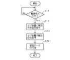
まず、ファイル10を格納棚1に格納する際には、図5のフローチャートに示すように、ステップS11において、入力部62を介して被検索物の特定情報、本実施形態では格納されるファイル10に係る書類名の入力が有るか否かが判定され、ここで、例えば、ファイル10を格納棚1に格納しようとする作業者が、入力部62を介してその格納しようとするファイル10の書類名を入力すると、ステップS12にすすんで、識別符号取得装置50を通じてその筺体51にセットされたタグ装置20に向けて識別符号返答指令を含む赤外信号が送信される。
【0043】
すると、タグ装置20よりその固有の識別符号を含む光信号が送信されるので、ステップS13にすすんで、その光信号が識別符号取得装置50を介して受信され、当該タグ装置20に割当てられた固有の識別符号が取得される。
【0044】
次に、ステップS14において、その取得したタグ装置20の固有の識別符号を入力された書類名に関連づけた検索管理データが作成される。
【0045】
一方、ファイル10を格納棚1から取出す際には、図6のフローチャートに示すように、ステップS21において、取出すべきファイル10に係る書類名の入力が有るか否かが判定され、ここで、例えば、いずれかのファイル10を取出そうとする作業者が、そのファイル10の書類名を入力すると、ステップS22にすすんで、前記検索管理データに基づいて当該入力された書類名に対応する識別符号が検索される。
【0046】
そして、ステップS23にすすんで、設置型送信装置64を通じて当該検索された呼出用の識別符号を含む光信号が携帯型用送信装置に向けて送信され、その後、ステップS24において、その識別符号に対応するファイル10が非格納状態にある点につき、検索管理データの更新が行われる。
【0047】
また、呼び出し用の携帯用送信装置70は、図7及び図8に示すように、一次電池71a又は一次電池71a及び充電池71bを併用した電源部71を電源として動作するもので、マイコン制御部73、赤外光受光素子76aにより受光された赤外光信号を電気信号に変換しこれをマイコン制御部73に出力する受信部76、マイコン制御部73からの出力信号を赤外光信号として送信する赤外線LED等の送信用発光素子74、マイコン制御部73へ所定の指令を入力するためのテンキー等の入力部75及び所定の情報を表示するためのLCD表示器等の表示部72とを備える。
【0048】
上記マイコン制御部73は、CPU、ROMおよびRAM等を備える一般的なマイクロコンピュータが使用され、予め格納されたソフトウェアプログラムによって次の動作を行う。
【0049】
即ち、識別符号管理装置60の設置型送信装置64との赤外線通信により、呼出用の識別符号を含む信号が受信部76の赤外光受光素子76aにより受信され、これがマイコン制御部73に入力されると、当該呼出用の識別符号を一時的に記憶しておく。このように呼出用の識別符号を記憶した状態で、入力部75を通じて所望の物品の呼出指令が入力されると、前記記憶した識別符号を含む信号を送信用発光素子74により赤外光信号として送信するように構成される。
【0050】
次にこの被検索物管理システムにおけるファイル10の格納作業、及びファイル10の取出作業について説明する。
【0051】
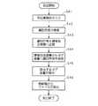
まず、ファイル10の格納作業は、図9のフローチャートに示す手順に従って行われる。
【0052】
即ち、ステップS31において、格納作業者が格納しようとするファイル10に係る書類名を管理装置60に入力すると共に、そのファイル10に取付けようとする一つのタグ装置20を、識別符号取得装置50にセットする。すると、ステップS32において、管理装置60により当該セットされたタグ装置20の識別符号が取得され、この識別符号が前記入力された書類名に関連づけられて管理データが作成される。
【0053】
その後、ステップS33において、格納作業者が前記セットしておいたタグ装置20をファイル10に取付けて、次に、ステップS34において、そのファイル10を格納棚1に格納すると、格納作業が終了する。
【0054】
また、ファイル10の取出作業は、図10のフローチャートに示す手順に従って行われる。
【0055】
まず、ステップS41において、取出作業者が本システムを利用して取出そうとするファイル10に係る書類名を管理装置60に入力すると、ステップS42にすすんで、管理装置60により管理データに基づいてその書類名に対応する識別符号が検索され、続いて、ステップS43において、その呼出用の識別符号を含む信号が識別符号管理装置60から携帯用送信装置70に送信され、呼出用の識別符号が携帯用送信装置70に記憶される。
【0056】
次に、ステップS44では、取出作業者が、携帯用送信装置70を格納棚1の手前に構えて呼出指令を入力する。すると、携帯用送信装置70から格納棚1の各ファイル10のタグ装置20に向けて前記呼出用の識別符号を含む信号が送信される。そして、ステップS45では、各タグ装置20が前記呼出用の識別符号を含む信号を受信して、各タグ装置20の中から、前記呼出用の識別符号と一致する固有の識別符号が割当てられたタグ装置20が発光する。
【0057】
そして、ステップS46において、取出作業者が前述のタグ装置20の発光を手掛りとして所望のファイル10の格納位置を容易に特定できるので、その発光したタグ装置20が取付けられた物品を取出す。このようにして、取出作業が終了する。
【0058】
以上のように構成されたタグ装置20によると、記憶部42aとして、バックアップ用の電源供給無しに記憶した内容を保持可能な不揮発性のものを用いているため、例えば、タグ制御部42への電源供給が途絶えたときであっても、より確実に固有の識別符号のデータを保持し続けることができ、従って、そのタグ装置20に割当てられた固有の識別符号に基づいてより確実にファイル10の検索を行うことができる。
【0059】
また、受信用光電素子35を通じて識別符号返答指令を含む赤外光信号を受信したときに、報知送信兼用発光素子48から自己の固有の識別符号が含まれた信号を送信させるようにしたタグ制御部42を備えているため、タグ装置20側で固有の識別符号の書換え等をする必要が無くなり、よって、その記憶部42aとしてはタグ装置20に実装された状態で読取専用に機能するもの、例えば、マスクROMやヒューズROM、EPROMの他、書換回路無しで実装したEEPROM等を用いることができ、その大型化や製造コストの上昇、消費電力増を防止することができる。
【0060】
なお、上記実施形態では、自己の固有の識別符号が含まれた信号を送信させるための報知送信兼用発光素子48を、発光により作業者に自己の位置を報知するための報知手段としても用いているが、自己の固有の識別符号が含まれた信号を送信させるための送信手段と、発光により作業者に自己の位置を報知するための報知手段とを別々に設けた構成であってもよい。もっとも、報知送信兼用の発光素子48を用いると、その全体的な構成の簡略化を図ることができる。
【0061】
また、管理装置60では、タグ装置20に識別符号返答指令の赤外光信号を送信する管理装置側発光部52aと、タグ装置20から送信された光信号を受信する管理装置側受光部52bと、書類名の入力により、管理装置側発光部52aから識別符号返答指令の光信号を送信させる一方、これに応答したタグ装置20からの光信号が管理装置側受光部52bを通じて受信されると、その信号に含まれる識別符号を前記入力された書類名と関連づけて管理データを作成するコンピュータ本体部61とを備えているため、書換不能に固有の識別符号を記憶したタグ装置20側からその固有の識別符号を取得して検索管理データを作成することができる。
【0062】
B.応用例
図11は、上述の被検索物管理システムの応用例を示す図である。
【0063】
この管理システムでは、格納棚1A(1),1A(2),1A(3)・・・/格納棚1B(1),1B(2),1B(3)・・・が2列に並べて相対向して設けられており、各格納棚1A(1),1A(2),1A(3)・・・に対向する各格納棚1B(1),1B(2),1B(3)・・・の前部に当該各格納棚1A(1),1A(2),1A(3)・・・に格納されたファイル10を検索するための棚検索部80A(1),80A(2)・・・がそれぞれ設けられると共に、各格納棚1B(1),1B(2),1B(3)・・・に対向する各格納棚1A(1),1A(2),1A(3)・・・の前部に当該各格納棚1B(1),1B(2),1B(3)・・・に格納されたファイル10を検索するための棚検索部80B(1),80B(2)・・・がそれぞれ設けられている。
【0064】
このうち棚検索部80A(1)は、ファイル10のタグ装置20との間で光通信を行うための発光部、受光部及びこれらの動作制御用の制御部を備えており、その発光部から所定の識別符号を含む検索光信号がその対面の格納棚1A(1)に格納された各ファイル10のタグ装置20により受信可能に構成されると共に、その受光部により当該格納棚1A(1)に格納された各ファイル10のタグ装置20から送信された光信号を受信可能に構成されている。また、他の棚検索部80A(2)・・・/80B(1),80B(2)・・・についても、対面の格納棚1A(2)・・・/1B(1),1B(2)・・・に格納されたファイル10のタグ装置20との間で上記と同様の光通信を行うように構成されている。
【0065】
また、各ファイル10に取付けられるタグ装置20には、上記実施形態における構成に加えて、前記棚検索部80A(1)からの検索光信号を受信してその検索光信号に含まれる識別符号が自己の識別符号と一致するか否かを判定すると共に、一致した場合に、その一致した旨の検索応答光信号を送信する機能が付加されている。
【0066】
そして、例えば、管理装置60側からの検索指令により、棚検索部80A(1)から所定の識別符号を含む検索光信号を送信する一方で、対面する格納棚1A(1)に格納されたファイル10のタグ装置20からの検索応答光信号を待ち、ここでいずれかのタグ装置20からの検索応答光信号が受信されると、当該格納棚1A(1)にその所定の識別符号のタグ装置20が取付けられたファイル10が格納されていることが認識され、一方、受信無き場合には、当該格納棚1A(1)にその所定の識別符号のタグ装置20が取付けられたファイル10が格納されていないことが認識される。
【0067】
この検索動作を、他の80A(2)・・・/80B(1),80B(2)・・・によっても繰り返し行い、また、他の識別符号についても順次繰り返し行うことにより、所定の識別符号を有するタグ装置20を取付けたファイル10が、いずれの各格納棚1A(1),1A(2),1A(3)・・・/1B(1),1B(2),1B(3)・・・に格納されているかを検索することができ、また、この検索結果を基に格納位置と識別符号とを関連づけたデータベースを構築することができる。
【0068】
そして、このデータベースに基づいて、所定の識別符号を有するタグ装置20を取付けたファイル10を取出す際に、表示部63にそのファイル10が格納された格納棚1A(1),1A(2),1A(3)・・・/1B(1),1B(2),1B(3)・・・を表示させたり、また、各格納棚1A(1),1A(2),1A(3)・・・/1B(1),1B(2),1B(3)・・・に予め設けられた発光表示部の選択駆動により、そのファイル10が格納された格納棚1A(1),1A(2),1A(3)・・・/1B(1),1B(2),1B(3)・・・を発光表示させるようにすることもできる。
【0069】
さらに、より詳細なファイル10の格納位置を認識したい場合には、各格納棚1A(1),1A(2),1A(3)・・・/1B(1),1B(2),1B(3)・・・の各棚段に、ファイル10の配列方向に沿ってそれぞれ個別にファイル10のタグ装置20との間で光通信可能な検索制御部を列設し、この各検索制御部と各ファイル10のタグ装置20との間の光通信により当該タグ装置20の識別符号を取得し、これにより、その棚段や棚段上の配列位置まで区別した格納位置と識別符号とを関連づけたデータベースを構築することができる。
【0070】
また、この場合、棚段上の配列位置まで区別することができるので、棚段のファイル10の配列位置に対応してそれぞれ発光表示部を設けておき、前記構築されたデータベースに基づいて各発光表示部を選択駆動させることにより、当該ファイル10の収納位置を発光表示させるようにしてもよい。
【0071】
この場合には、タグ装置20における報知用の発光手段を省略しても、所定のファイル10の収納位置を認識することができる。
【0072】
【発明の効果】
以上のように、この発明の請求項1記載の被検索物管理システム用のタグ装置によると、受信手段を通じて識別符号返答指令信号を受信したときに、タグ側送信手段から固有の識別符号が含まれた信号を送信させるようにしたタグ制御部を備えているため、タグ装置側で固有の識別符号を書換える等する必要が無くなり、よって、書換回路等が不要な不揮発性読出専用記憶部を採用して、その大型化や製造コストの上昇、消費電力増を防止することができる。
【0073】
また、タグ制御部の不揮発性読出専用記憶部に、固有の識別符号を記憶させているため、例えば、タグ制御部への電源供給が途絶えたときであっても、より確実に固有の識別符号のデータを保持し続けることができ、従って、そのタグ装置に割当てられた固有の識別符号に基づいてより確実に被検索物の検索を行うことができる。
【0074】
また、タグ装置が、呼出用の識別符号を含む呼出信号を受信する呼出用受信手段をさらに備えると共に、このタグ制御部が、その呼出用受信手段により受信された呼出信号に含まれる識別符号と自己の固有の識別符号とが一致するか否かを判定する機能をさらに備え、タグ側送信手段として、可視光信号により返答信号を送信する可視光発光手段が用いられ、前記タグ制御部が、前記呼出信号に含まれる識別符号と自己の固有の識別符号と一致したと判定した際に、前記可視光発光手段を発光させることによりその一致した旨を外部に報知するようにしているため、固有の識別符号が含まれた返答信号を送信するタグ側送信手段が、識別符号が一致した旨を外部に報知するための可視光発光手段としても用いられるため、発光による報知する構成を取入れつつタグ装置の構成の簡略化を図ることができる。
【0076】
また、この発明の請求項3記載の被検索物管理システムによると、タグ装置側に、受信手段を通じて識別符号返答指令信号を受信したときに、タグ側送信手段から固有の識別符号が含まれた信号を送信させるようにしたタグ制御部が備えられているため、タグ装置側で固有の識別符号を書換える等する必要が無くなり、よって、書換回路等が不要な不揮発性読出専用記憶部を採用して、その大型化や製造コストの上昇、消費電力増を防止することができる。また、そのタグ制御部の不揮発性読出専用記憶部に、固有の識別符号を記憶させているため、例えば、タグ制御部への電源供給が途絶えたときであっても、より確実に固有の識別符号のデータを保持し続けることができ、従って、そのタグ装置に割当てられた固有の識別符号に基づいてより確実に被検索物の検索を行うことができる。そして、管理装置側にあっては、タグ装置に識別符号返答指令信号を送信する管理装置側送信手段と、タグ装置から送信された返答信号を受信する管理装置側受信手段と、被検索物の特定情報の入力により、前記管理側送信手段から識別符号返答指令信号を送信させる一方、これに応答したタグ装置からの返答信号が前記管理側受信手段を通じて受信されると、その返答信号に含まれる識別符号を被検索物の特定情報と関連づけて管理データを作成する管理制御部と、を備えているため、書換不能に固有の識別符号を記憶した上記タグ装置側から、その固有の識別符号を取得して検索管理データを作成することができる。
【0077】
さらに、この発明の請求項4記載の被検索物管理方法によると、被検索物に取付けられるタグ装置として、識別符号返答指令信号を受信するタグ側受信手段と、固有の識別符号が含まれた返答信号を送信するタグ側送信手段と、固有の識別符号のデータを記憶した不揮発性読出専用記憶部を有し前記受信手段を通じて識別符号返答指令信号を受信したときに、前記タグ側送信手段から前記固有の識別符号が含まれた信号を送信させるタグ制御部とを有するタグ装置が用いられ、いずれかの被検索物に取付けられるタグ装置に対して識別符号返答指令を与えることにより、そのタグ装置から前記割当てられた固有の識別符号を取得し、その取得した識別符号を、当該タグ装置の特定情報に関連づけて管理データを作成しているため、大型化や製造コストの上昇、消費電力増を防止でき、かつ、より確実に固有の識別符号のデータを保持し続けることができる不揮発性記憶部を用いたタグ装置からその固有の識別符号を取得し、検索管理データを作成することができる。
【図面の簡単な説明】
【図1】この発明にかかる一実施形態の被検索物管理システムの基本構成を示す図である。
【図2】図2(a)はタグ装置の平面図、図2(b)はタグ装置の正面図、図2(c)はタグ装置の側面図である。
【図3】タグ装置の電気的構成を示すブロック図である。
【図4】タグ装置の動作を示すフローチャートである。
【図5】ファイル格納の際における管理装置の動作を示すフローチャートである。
【図6】ファイル取出の際における管理装置の動作を示すフローチャートである。
【図7】携帯用送信装置の正面図である。
【図8】携帯用送信装置の電気的構成を示すブロック図である。
【図9】被検索物管理システムにおけるファイル格納手順を示すフローチャートである。
【図10】被検索物管理システムにおけるファイル取出手順を示すフローチャートである。
【図11】この被検索物管理システムの応用例を示す図である。
【図12】従来のタグ装置の電気的構成を示すブロック図である。
【符号の説明】
1 格納棚
10 ファイル
20 タグ装置
30 タグ本体部
35 受信用光電素子
42 タグ制御部
42a 記憶部
48 報知送信兼用発光素子
50 識別符号取得装置
52a 管理装置側発光部
52b 管理装置側受光部
60 識別符号管理装置[0001]
BACKGROUND OF THE INVENTION
The present invention relates to a tag device for a search object management system that manages search objects such as files.PlaceThe present invention relates to a search object management system and a search object management method.
[0002]
[Background]
As one type of search object management system for storing and managing files and the like, there is a system in which tag devices each having a unique identification code are attached to each file and then stored in those file storage shelves.
[0003]
In this management system, when each file is stored in the storage shelf, the document name bound to the file to be stored and the identification code assigned to the file are sent to the management device of the management system using a personal computer or the like. Create search management data that registers and associates them with each other, and writes the assigned identification code to a predetermined tag device by an identification code registration device connected to the management device. It is attached and the file is stored in the storage shelf.
[0004]
In this management system, based on the search management data, the identification number of the tag device attached to the file can be easily retrieved from the document name bound in the file. For example, a call signal including a call identification code is transmitted to the tag device of each file stored in the storage shelf, while the call identification code is unique to each tag device. It is possible to easily search for a file attached with a tag device having the identification number by using the light emission as a clue by causing the corresponding tag device side to emit light when it matches. can do.
[0005]
FIG. 12 is a diagram showing an electrical configuration of a tag device used in such a management system.
[0006]
This tag device is configured according to a software program stored in a
[0007]
Further, the
[0008]
In addition, the tag device includes a
[0009]
[Problems to be solved by the invention]
By the way, since the search object management system as described above employs a method of writing the identification code assigned on the management device side to the tag device, the tag device side stores the assigned identification code in the
[0010]
However, if the tag device is left in a dark place for a long time, the
[0011]
The same applies to the case where a button type primary battery or the like is used as the power source.
[0012]
In this case, even if the
[0013]
In order to avoid this, a means for mounting a rewritable nonvolatile memory such as an EEPROM in the tag device together with the rewriting circuit can be considered.
[0014]
However, in this case, the rewriting circuit causes an increase in the size of the tag device, an increase in manufacturing cost, and an increase in power consumption during operation of the tag device due to an increase in the mounting area of the electronic component. In addition, when a system is configured using such a tag device, the identification code assigned to the tag device can be seen from the outside in order to manage what identification code is assigned to each tag device. It was necessary to display by a method such as printing or attaching a label.
[0015]
Therefore, the present invention has been made to solve each of the problems as described above, and can more reliably search for an object to be searched without increasing the size, increasing the manufacturing cost, or increasing the power consumption. Providing a tag device for a search object management system and suitable for use of such a tag deviceCoverIt is an object to provide a search object management system and a search object management method.
[0016]
[Means for Solving the Problems]
In order to solve the above-described problem, the invention according to
[0017]
Also,Call reception means for receiving a call signal including a call identification code, wherein the tag control unit includes an identification code included in the call signal received by the call reception means and a unique identification code of itself; The tag side transmission means is a visible light emitting means for transmitting a response signal using a visible light signal, and the tag control unit is included in the calling signal. When it is determined that the identification code matched with its own unique identification code, the visible light emitting means is caused to emit light to notify the outside of the coincidence.ing.
[0018]
In this case, as in
[0019]
And claims3In the described object management system in which a plurality of search objects are stored in a storage shelf, a tag device is attached to each search object, and a unique identification code assigned to each tag device is assigned to each search object. A search object management system for creating management data in association with specific information of a search object, a tag side receiving means for receiving an identification code response command signal, and a tag for transmitting a response signal including a unique identification code And a non-volatile read-only storage unit that stores data of a unique identification code, and when the identification code response command signal is received through the receiving means, the unique identification code is received from the tag side transmission means. A tag device having a tag control unit for transmitting the contained signal, a management device side transmission means for transmitting an identification code response command signal to the tag device, and a response signal transmitted from the tag device An identification code response command signal is transmitted from the management-side transmission means by inputting management information on the management-device-side receiving means and information to be searched, and a response signal from the tag device responding thereto is transmitted through the management-side reception means. A management device having a management control unit that creates management data by associating the identification code included in the response signal with the specific information of the search target when received,The tag device further includes call reception means for receiving a call signal including a call identification code, and the tag control unit includes an identification code included in the call signal received by the call reception means and its own code. A function of determining whether or not the unique identification code matches, visible light emitting means for transmitting a response signal by a visible light signal is used as the tag-side transmitting means, and the tag control unit When it is determined that the identification code included in the calling signal matches its own unique identification code, the visible light emitting means is caused to emit light to notify the outside of the coincidence.Is.
[0020]
Claims4In the described invention, a plurality of search objects are stored in a storage shelf, a tag device is attached to each search object, and a unique identification code assigned to each tag device is associated with specific information of each search object. And a tag side receiving means for receiving an identification code response command signal and a tag side for transmitting a response signal including a unique identification code as each tag device. The unique identification code is included from the tag-side transmission means when the identification means response command signal is received through the reception means having a non-volatile read-only storage unit storing the unique identification code data. A tag device having a tag control unit for transmitting the received signal,The tag device further includes call reception means for receiving a call signal including a call identification code, and the tag control unit includes an identification code included in the call signal received by the call reception means and its own code. A function of determining whether or not the unique identification code matches, visible light emitting means for transmitting a response signal by a visible light signal is used as the tag-side transmitting means, and the tag control unit When it is determined that the identification code included in the paging signal matches its own unique identification code, the visible light emitting means is caused to emit light to notify the outside,By giving an identification code response command to the tag device attached to any of the search objects, the assigned unique identification code is acquired from the tag device, and the acquired identification code is obtained from the tag device. Management data is created in association with specific information.
[0021]
DETAILED DESCRIPTION OF THE INVENTION
A. Embodiment
The search object management system according to the first embodiment of the present invention will be described below.
[0022]
As shown in FIG. 1, in this search object management system, a
[0023]
As shown in FIG. 1 and FIGS. 2A to 2B, the
[0024]
The tag
[0025]
The
[0026]
Further, a
[0027]
Further, the
[0028]
That is, the
[0029]
The receiving
[0030]
The notification transmission /
[0031]
The charging
[0032]
In the
Further, as the charging
[0033]
Instead of the power supply circuit having the charging
[0034]
The
[0035]
The storage unit 42a stores in advance a software program for operation control of the
[0036]
That is, as shown in step S1, the
[0037]
If it is determined in step S2 that the input signal is a signal including an identification code response command, the process proceeds to step S3, and a signal including a unique identification code stored in its own storage unit 42a is used for notification transmission. A light signal is transmitted from the
[0038]
On the other hand, if it is determined in step S2 that the signal includes a call instruction, in step S4, the call identification code included in the call signal is stored in the own storage unit 42a. It is determined whether or not it matches the identification code. If they match, the process proceeds to step S5.
[0039]
The
[0040]
In the identification
[0041]
The
[0042]
First, when the
[0043]
Then, since an optical signal including the unique identification code is transmitted from the
[0044]
Next, in step S14, search management data in which the acquired unique identification code of the
[0045]
On the other hand, when the
[0046]
Then, proceeding to step S23, an optical signal including the retrieved call identification code is transmitted to the portable transmission device through the
[0047]
Further, as shown in FIGS. 7 and 8, the
[0048]
As the
[0049]
That is, by infrared communication with the
[0050]
Next, the storing operation of the
[0051]
First, the storing operation of the
[0052]
That is, in step S31, the document name related to the
[0053]
After that, in step S33, the
[0054]
The
[0055]
First, in step S41, when the extraction operator inputs the document name related to the
[0056]
Then stepS44Then, the take-out operator holds the
[0057]
In step S46, the take-out operator can easily specify the storage position of the desired
[0058]
According to the
[0059]
In addition, when an infrared light signal including an identification code response command is received through the receiving
[0060]
In the above-described embodiment, the notification transmission /
[0061]
Further, in the
[0062]
B. Application examples
FIG. 11 is a diagram showing an application example of the search object management system described above.
[0063]
In this management system, storage shelves 1A (1), 1A (2), 1A (3)... / Storage shelves 1B (1), 1B (2), 1B (3). The storage shelves 1B (1), 1B (2), 1B (3),... Facing each storage shelf 1A (1), 1A (2), 1A (3). . The
[0064]
Of these, the
[0065]
In addition to the configuration in the above embodiment, the
[0066]
Then, for example, in response to a search command from the
[0067]
This search operation is repeated with the other 80A (2)... / 80B (1), 80B (2)... And the other identification codes are also sequentially repeated to obtain a predetermined identification code. Each of the storage shelves 1A (1), 1A (2), 1A (3) ... / 1B (1), 1B (2), 1B (3) .. Can be searched, and a database in which the storage position is associated with the identification code can be constructed based on the search result.
[0068]
Based on this database, when the
[0069]
Further, when it is desired to recognize the storage position of the
[0070]
In this case, since it is possible to distinguish up to the arrangement position on the shelf, a light emission display unit is provided corresponding to the arrangement position of the
[0071]
In this case, the storage position of the
[0072]
【The invention's effect】
As described above, according to the tag device for the search object management system according to the first aspect of the present invention, when the identification code response command signal is received through the receiving means, the unique identification code is included from the tag side transmitting means. Since the tag control unit is configured to transmit the received signal, it is not necessary to rewrite the unique identification code on the tag device side, and therefore a nonvolatile read-only storage unit that does not require a rewrite circuit or the like is provided. By adopting it, it is possible to prevent an increase in size, an increase in manufacturing cost, and an increase in power consumption.
[0073]
In addition, since the unique identification code is stored in the nonvolatile read-only storage unit of the tag control unit, for example, even when the power supply to the tag control unit is interrupted, the unique identification code is more reliably generated. Therefore, the search object can be searched more reliably based on the unique identification code assigned to the tag device.
[0074]
Also,The tag device further includes call reception means for receiving a call signal including a call identification code, and the tag control unit includes the identification code included in the call signal received by the call reception means and its own code. Further equipped with a function to determine whether or not the unique identification code matchese,Visible light emitting means for transmitting a response signal using a visible light signal is used as the tag side transmitting means, and the tag control unit determines that the identification code included in the calling signal matches its own unique identification code. In such a case, the visible light emitting means is caused to emit light so as to notify the outside of the coincidence.BecauseSince the tag-side transmission means for transmitting a response signal including a unique identification code is also used as a visible light emitting means for notifying the outside that the identification codes match, the structure for notifying by light emission is adopted. It is possible to simplify the configuration of the tag device.
[0076]
Further, the claims of the present invention3According to the search object management system described, the tag device is configured to cause the tag device side to transmit a signal including a unique identification code from the tag side transmission unit when the identification code response command signal is received through the reception unit. Since the control unit is provided, there is no need to rewrite the unique identification code on the tag device side, so a non-volatile read-only storage unit that does not require a rewriting circuit or the like is adopted, and its size and manufacturing are increased. An increase in cost and an increase in power consumption can be prevented. Further, since the unique identification code is stored in the nonvolatile read-only storage unit of the tag control unit, for example, even when the power supply to the tag control unit is interrupted, the unique identification is more reliably performed. The data of the code can continue to be held, and therefore the search target can be searched more reliably based on the unique identification code assigned to the tag device. On the management device side, the management device side transmission means for transmitting the identification code response command signal to the tag device, the management device side reception means for receiving the response signal transmitted from the tag device, and the search object An identification code response command signal is transmitted from the management side transmission means by inputting specific information, and when a response signal from the tag device responding thereto is received through the management side reception means, it is included in the response signal And a management control unit that creates management data by associating the identification code with the specific information of the search target object, so that the unique identification code is stored from the tag device side storing the unique identification code that cannot be rewritten. Retrieve and create search management data.
[0077]
Further claims of the invention4According to the described search object management method, as a tag device attached to the search object, tag side receiving means for receiving an identification code response command signal, and tag side transmission for transmitting a response signal including a unique identification code And a non-volatile read-only storage unit storing unique identification code data, and when the identification code response command signal is received through the receiving means, the unique identification code is included from the tag side transmission means. A tag device having a tag control unit that transmits the received signal, and giving an identification code response command to the tag device attached to any of the objects to be searched. Since the identification code is acquired and the management data is created by associating the acquired identification code with the specific information of the tag device, the size is increased, the manufacturing cost is increased, and the power consumption is increased. Prevention can, and more reliably acquire the unique identification code from the tag device using a nonvolatile memory unit can continue to hold data for unique identification code, it is possible to create a search management data.
[Brief description of the drawings]
FIG. 1 is a diagram showing a basic configuration of a search object management system according to an embodiment of the present invention.
2A is a plan view of the tag device, FIG. 2B is a front view of the tag device, and FIG. 2C is a side view of the tag device.
FIG. 3 is a block diagram showing an electrical configuration of the tag device.
FIG. 4 is a flowchart showing the operation of the tag device.
FIG. 5 is a flowchart showing the operation of the management apparatus when storing a file.
FIG. 6 is a flowchart showing the operation of the management apparatus when extracting a file.
FIG. 7 is a front view of the portable transmission device.
FIG. 8 is a block diagram showing an electrical configuration of the portable transmission device.
FIG. 9 is a flowchart showing a file storage procedure in the search target object management system.
FIG. 10 is a flowchart showing a file extraction procedure in the search object management system.
FIG. 11 is a diagram showing an application example of this search object management system.
FIG. 12 is a block diagram showing an electrical configuration of a conventional tag device.
[Explanation of symbols]
1 Storage shelf
10 files
20 Tag device
30 Tag body
35 Photoelectric element for reception
42 Tag control unit
42a storage unit
48 Light emitting element for notification transmission
50 Identification code acquisition device
52a Management device side light emitting section
52b Light-receiving unit on management device
60 Identification code management device
Claims (4)
Translated fromJapanese識別符号返答指令信号を受信するタグ側受信手段と、
固有の識別符号が含まれた返答信号を送信するタグ側送信手段と、
固有の識別符号のデータを記憶した不揮発性読出専用記憶部を有し、前記受信手段を通じて識別符号返答指令信号を受信したときに、前記タグ側送信手段から前記固有の識別符号が含まれた信号を送信させるタグ制御部と、を備え、
呼出用の識別符号を含む呼出信号を受信する呼出用受信手段をさらに備え、前記タグ制御部が、その呼出用受信手段により受信された呼出信号に含まれる識別符号と自己の固有の識別符号とが一致するか否かを判定する機能をさらに備えており、
前記タグ側送信手段として、可視光信号により返答信号を送信する可視光発光手段が用いられ、
前記タグ制御部が、前記呼出信号に含まれる識別符号と自己の固有の識別符号と一致したと判定した際には、前記可視光発光手段を発光させることによりその一致した旨を外部に報知する、被検索物管理システム用のタグ装置。In a search object management system in which a plurality of search objects are stored in a storage shelf, a tag device is attached to each search object, and a unique identification code assigned to each tag device is specified for each search object. A tag device for a search object management system that creates search management data in association with information,
Tag-side receiving means for receiving an identification code response command signal;
Tag-side transmission means for transmitting a response signal including a unique identification code;
A non-volatile read-only storage unit that stores data of a unique identification code, and when the identification code response command signal is received through the receiving means, a signal including the unique identification code from the tag-side transmission means Beiexample and a tag control unit to transmita
Call reception means for receiving a call signal including a call identification code, wherein the tag control unit includes an identification code included in the call signal received by the call reception means and a unique identification code of itself; And a function to determine whether or not match,
Visible light emitting means for transmitting a response signal by a visible light signal is used as the tag side transmitting means,
When the tag control unit determines that the identification code included in the call signal matches its own unique identification code, the visible light emitting means is caused to emit light to notify the outside of the match. , tag device for the retrieval object management system.
電源用の充電素子を充電する充電用光電素子をさらに備え、 It further comprises a charging photoelectric element for charging a charging element for power supply,
前記充電用光電素子と前記タグ側受信手段とが、同一面側に設けられている、被検索物管理システム用のタグ装置。 A tag device for a search object management system, wherein the charging photoelectric element and the tag side receiving means are provided on the same surface side.
識別符号返答指令信号を受信するタグ側受信手段と、固有の識別符号が含まれた返答信号を送信するタグ側送信手段と、固有の識別符号のデータを記憶した不揮発性読出専用記憶部を有し前記受信手段を通じて識別符号返答指令信号を受信したときに、前記タグ側送信手段から前記固有の識別符号が含まれた信号を送信させるタグ制御部と、を有するタグ装置と、
タグ装置に識別符号返答指令信号を送信する管理装置側送信手段と、タグ装置から送信された返答信号を受信する管理装置側受信手段と、被検索物の特定情報の入力により、前記管理側送信手段から識別符号返答指令信号を送信させる一方、これに応答したタグ装置からの返答信号が前記管理側受信手段を通じて受信されると、その返答信号に含まれる識別符号を被検索物の特定情報と関連づけて管理データを作成する管理制御部とを有する管理装置と、
を備え、
前記タグ装置が、呼出用の識別符号を含む呼出信号を受信する呼出用受信手段をさらに備え、前記タグ制御部が、その呼出用受信手段により受信された呼出信号に含まれる識別符号と自己の固有の識別符号とが一致するか否かを判定する機能をさらに備えており、
前記タグ側送信手段として、可視光信号により返答信号を送信する可視光発光手段が用いられ、
前記タグ制御部が、前記呼出信号に含まれる識別符号と自己の固有の識別符号と一致したと判定した際には、前記可視光発光手段を発光させることによりその一致した旨を外部に報知する、被検索物管理システム。In a search object management system in which a plurality of search objects are stored in a storage shelf, a tag device is attached to each search object, and a unique identification code assigned to each tag device is specified as identification information of each search object creating management data in association witha search target object managementsystem,
There is provided a tag side receiving means for receiving an identification code response command signal, a tag side transmitting means for transmitting a response signal including a unique identification code, and a non-volatile read-only storage section storing data of the unique identification code. A tag control unit that, when receiving an identification code response command signal through the receiving unit, causes the tag side transmitting unit to transmit a signal including the unique identification code;
The management apparatus side transmission means for transmitting the identification code response command signal to the tag apparatus, the management apparatus side reception means for receiving the response signal transmitted from the tag apparatus, and the management side transmission by inputting the specific information of the search object When the response signal from the tag device responding thereto is received through the management side receiving means, the identification code included in the response signal is used as the specific information of the search object. A management device having a management control unit that creates management data in association with each other;
With
The tag device further includes call reception means for receiving a call signal including a call identification code, and the tag control unit includes an identification code included in the call signal received by the call reception means and its own code. A function of determining whether or not the unique identification code matches,
Visible light emitting means for transmitting a response signal by a visible light signal is used as the tag side transmitting means,
When the tag control unit determines that the identification code included in the call signal matches its own unique identification code, the visible light emitting means is caused to emit light to notify the outside of the match. Searched object management system.
前記各タグ装置として、識別符号返答指令信号を受信するタグ側受信手段と、固有の識別符号が含まれた返答信号を送信するタグ側送信手段と、固有の識別符号のデータを記憶した不揮発性読出専用記憶部を有し前記受信手段を通じて識別符号返答指令信号を受信したときに、前記タグ側送信手段から前記固有の識別符号が含まれた信号を送信させるタグ制御部とを有するタグ装置が用いられ、 As each of the tag devices, a tag-side receiving unit that receives an identification code response command signal, a tag-side transmission unit that transmits a response signal including a unique identification code, and a nonvolatile memory that stores data of a unique identification code A tag device having a read-only storage unit and a tag control unit for transmitting a signal including the unique identification code from the tag-side transmission unit when an identification code response command signal is received through the reception unit; Used,
前記タグ装置が、呼出用の識別符号を含む呼出信号を受信する呼出用受信手段をさらに備え、前記タグ制御部が、その呼出用受信手段により受信された呼出信号に含まれる識別符号と自己の固有の識別符号とが一致するか否かを判定する機能をさらに備えており、前記タグ側送信手段として、可視光信号により返答信号を送信する可視光発光手段が用いられ、前記タグ制御部が、前記呼出信号に含まれる識別符号と自己の固有の識別符号と一致したと判定した際には、前記可視光発光手段を発光させることによりその一致した旨を外部に報知するものであり、 The tag device further includes call reception means for receiving a call signal including a call identification code, and the tag control unit includes an identification code included in the call signal received by the call reception means and its own code. A function of determining whether or not the unique identification code matches, visible light emitting means for transmitting a response signal by a visible light signal is used as the tag-side transmitting means, and the tag control unit When it is determined that the identification code included in the paging signal matches its own unique identification code, the visible light emitting means is caused to emit light to notify the outside,
いずれかの被検索物に取付けられるタグ装置に対して識別符号返答指令を与えることにより、そのタグ装置から前記割当てられた固有の識別符号を取得し、その取得した識別符号を、当該タグ装置の特定情報に関連づけて管理データを作成する被検索物管理方法。 By giving an identification code response command to the tag device attached to any of the search objects, the assigned unique identification code is acquired from the tag device, and the acquired identification code is obtained from the tag device. A search object management method for creating management data in association with specific information.
Priority Applications (1)
| Application Number | Priority Date | Filing Date | Title |
|---|---|---|---|
| JP31515199AJP4497603B2 (en) | 1999-11-05 | 1999-11-05 | Tag device for search object management system, search object management system, and search object management method |
Applications Claiming Priority (1)
| Application Number | Priority Date | Filing Date | Title |
|---|---|---|---|
| JP31515199AJP4497603B2 (en) | 1999-11-05 | 1999-11-05 | Tag device for search object management system, search object management system, and search object management method |
Publications (2)
| Publication Number | Publication Date |
|---|---|
| JP2001130718A JP2001130718A (en) | 2001-05-15 |
| JP4497603B2true JP4497603B2 (en) | 2010-07-07 |
Family
ID=18062038
Family Applications (1)
| Application Number | Title | Priority Date | Filing Date |
|---|---|---|---|
| JP31515199AExpired - Fee RelatedJP4497603B2 (en) | 1999-11-05 | 1999-11-05 | Tag device for search object management system, search object management system, and search object management method |
Country Status (1)
| Country | Link |
|---|---|
| JP (1) | JP4497603B2 (en) |
Families Citing this family (6)
| Publication number | Priority date | Publication date | Assignee | Title |
|---|---|---|---|---|
| JP4511246B2 (en)* | 2004-05-28 | 2010-07-28 | 株式会社国際電気通信基礎技術研究所 | Optical identification information acquisition device |
| EP1760013A4 (en)* | 2004-06-25 | 2011-05-04 | Nec Corp | Article position management system, article position management method, terminal device, server, and article position management program |
| JP2006024018A (en)* | 2004-07-08 | 2006-01-26 | Toshiba Tec Corp | Article search system and article storage case |
| JP4583950B2 (en)* | 2005-01-28 | 2010-11-17 | 株式会社エヌ・ティ・ティ・データ | Luggage management device and RF tag |
| JP2007094662A (en)* | 2005-09-28 | 2007-04-12 | Hitachi Electronics Service Co Ltd | Equipment specifying system and id tag |
| WO2010134154A1 (en)* | 2009-05-18 | 2010-11-25 | 株式会社日立製作所 | Optical communication system and optical communication method |
Family Cites Families (5)
| Publication number | Priority date | Publication date | Assignee | Title |
|---|---|---|---|---|
| GB9222460D0 (en)* | 1992-10-26 | 1992-12-09 | Hughes Microelectronics Europa | Radio frequency baggage tag |
| AU3921295A (en)* | 1994-12-13 | 1996-07-03 | Gay Freres Vente Et Exportation S.A. | Opto-electronic tag having an internal time base |
| JPH092621A (en)* | 1995-06-22 | 1997-01-07 | Daiwa Packs:Kk | Material management information system |
| JPH1059507A (en)* | 1996-08-21 | 1998-03-03 | Oki Electric Ind Co Ltd | Book management system |
| JP3343500B2 (en)* | 1997-08-26 | 2002-11-11 | 日本ファイリング株式会社 | Chart file search device |
- 1999
- 1999-11-05JPJP31515199Apatent/JP4497603B2/ennot_activeExpired - Fee Related
Also Published As
| Publication number | Publication date |
|---|---|
| JP2001130718A (en) | 2001-05-15 |
Similar Documents
| Publication | Publication Date | Title |
|---|---|---|
| JP4497603B2 (en) | Tag device for search object management system, search object management system, and search object management method | |
| JP5059390B2 (en) | Alarm, coupling adapter and data communication system | |
| NO842178L (en) | MACHINE FOR RECORDING, STORING AND TRANSFERING DATA, AND USING THE APPLIANCE AS A CONTROL | |
| JPH07247009A (en) | Individual retrieval control method for retrieved article such as clinical chart and device therefor | |
| JPH09237359A (en) | Group managing system for document | |
| GB2279789A (en) | File retrieval | |
| EP0681549B1 (en) | System for identifying, searching for and locating objects | |
| JP4412532B2 (en) | Goods management device | |
| JPH03249003A (en) | Electronic shelf label device | |
| JP3343500B2 (en) | Chart file search device | |
| JP2020022644A (en) | Picking support system | |
| JP2001048317A (en) | Tag device for article control system, article storing method in the system, and article control system | |
| JP2005335129A (en) | Document holding equipment, document management system | |
| US6297726B1 (en) | Radio paging receiver | |
| JP4803958B2 (en) | Article management apparatus, article management system, and article management method | |
| US20020171545A1 (en) | Article care seal | |
| JP2021192278A (en) | Facility terminal | |
| JPH10269339A (en) | Portable terminal device | |
| JP2008134910A (en) | Button for mobile device | |
| JP2949120B2 (en) | Document file search management device | |
| JP2791466B2 (en) | Individual search management method for search target such as medical chart and individual search management device | |
| KR20000007536U (en) | Remocon apparatus for receiving data by radio | |
| GB2364815A (en) | Method and Apparatus for the electronic recording of time | |
| JP4386703B2 (en) | Tag assembly holder | |
| FR2810767A1 (en) | Electronic label and archiving system for items using the labels, uses 'smart' label with internal time clock and stored expiry time, with communication circuit activated when time clock goes beyond stored expiry date |
Legal Events
| Date | Code | Title | Description |
|---|---|---|---|
| A621 | Written request for application examination | Free format text:JAPANESE INTERMEDIATE CODE: A621 Effective date:20061031 | |
| A521 | Request for written amendment filed | Free format text:JAPANESE INTERMEDIATE CODE: A523 Effective date:20061206 | |
| A521 | Request for written amendment filed | Free format text:JAPANESE INTERMEDIATE CODE: A523 Effective date:20070314 | |
| A977 | Report on retrieval | Free format text:JAPANESE INTERMEDIATE CODE: A971007 Effective date:20090715 | |
| RD04 | Notification of resignation of power of attorney | Free format text:JAPANESE INTERMEDIATE CODE: A7424 Effective date:20090924 | |
| A131 | Notification of reasons for refusal | Free format text:JAPANESE INTERMEDIATE CODE: A131 Effective date:20091013 | |
| A521 | Request for written amendment filed | Free format text:JAPANESE INTERMEDIATE CODE: A523 Effective date:20091214 | |
| TRDD | Decision of grant or rejection written | ||
| A01 | Written decision to grant a patent or to grant a registration (utility model) | Free format text:JAPANESE INTERMEDIATE CODE: A01 Effective date:20100413 | |
| A01 | Written decision to grant a patent or to grant a registration (utility model) | Free format text:JAPANESE INTERMEDIATE CODE: A01 | |
| A61 | First payment of annual fees (during grant procedure) | Free format text:JAPANESE INTERMEDIATE CODE: A61 Effective date:20100413 | |
| FPAY | Renewal fee payment (event date is renewal date of database) | Free format text:PAYMENT UNTIL: 20130423 Year of fee payment:3 | |
| R150 | Certificate of patent or registration of utility model | Free format text:JAPANESE INTERMEDIATE CODE: R150 | |
| FPAY | Renewal fee payment (event date is renewal date of database) | Free format text:PAYMENT UNTIL: 20140423 Year of fee payment:4 | |
| R250 | Receipt of annual fees | Free format text:JAPANESE INTERMEDIATE CODE: R250 | |
| R250 | Receipt of annual fees | Free format text:JAPANESE INTERMEDIATE CODE: R250 | |
| R250 | Receipt of annual fees | Free format text:JAPANESE INTERMEDIATE CODE: R250 | |
| R250 | Receipt of annual fees | Free format text:JAPANESE INTERMEDIATE CODE: R250 | |
| LAPS | Cancellation because of no payment of annual fees |