JP4497507B2 - Illumination optical system and projection display device using the same - Google Patents
Illumination optical system and projection display device using the sameDownload PDFInfo
- Publication number
- JP4497507B2 JP4497507B2JP2002380427AJP2002380427AJP4497507B2JP 4497507 B2JP4497507 B2JP 4497507B2JP 2002380427 AJP2002380427 AJP 2002380427AJP 2002380427 AJP2002380427 AJP 2002380427AJP 4497507 B2JP4497507 B2JP 4497507B2
- Authority
- JP
- Japan
- Prior art keywords
- light
- light source
- source unit
- optical system
- illumination optical
- Prior art date
- Legal status (The legal status is an assumption and is not a legal conclusion. Google has not performed a legal analysis and makes no representation as to the accuracy of the status listed.)
- Expired - Fee Related
Links
Images


Landscapes
- Projection Apparatus (AREA)
Description
Translated fromJapanese【0001】
【発明の属する技術分野】
本発明は、発光体およびリフレクタを備えた光源部を用いて被照明体を照明する照明光学系に関するもので、特に、照明光束をライトバルブにより光変調し、この投映光束によりスクリーン上に画像を拡大投映する投写型表示装置に好適な照明光学系、およびこれを用いた投写型表示装置に関するものである。
【0002】
【従来の技術】
近年、投写型表示装置においては明るい場所での投写でも問題なく利用できるよう、明るい投写型表示装置の開発が進められている。明るさの向上に大きく寄与する要素として、ライトバルブと並び、照明光学系の開発が進められている。例えば、特許文献1に記載されるような、複数の光源部を備えた照明光学系により光量増加を図るという構成がある。
【0003】
【特許文献1】
特開2001−21996号公報
【0004】
【発明が解決しようとする課題】
このように明るい光源部を数多く用いた照明光学系の構成により明るさを向上させるという手法は、従来より数多く提案されている。なかでも、コスト的に有利でかつ明るい光源部としては、リフレクタを備えた光源部が多く用いられている。しかし、同程度に明るい光源部を、多数用いた照明光学系は、これらの光源部およびこれらの光源部からの光束を合成する手段を配する必要があるため、大型化を免れない。
【0005】
照明光学系から出射される総量としての光量をできるだけ増加させることを最優先の目的とする場合はこのような構成も有効であるが、一方では、従来よりあるリフレクタを備えた光源部を改良し、構成の変更も少なく、照明光学系のサイズもコンパクトに、かつ、でき得る限り明るさ向上も図りたいという要望も存在する。従来よりあるリフレクタを備えた光源部、およびそれに対応した照明光学系や投写型表示装置の構成を少ない変更で利用することができれば、コスト的にも有利となる。
【0006】
本発明はこのような事情に鑑みなされたものであり、光源とリフレクタよりなる光源部から出射される光束の光量分布に着目し、従来からあるこのタイプの光源部に対し大きな設計変更を施すことなく、コンパクトでありながら、照明効率が高く、明るく均一な照明を行ない得る照明光学系およびこれを用いた投写型表示装置を提供することを目的とするものである。
【0007】
【課題を解決するための手段】
本発明に係る第1の照明光学系は、発光体およびこの発光体から出射された光を被照明体側に反射するリフレクタを備えた主要光源部と、この主要光源部からの光束の光量均一化を図る主要インテグレータ部と、前記主要光源部から出射された光束の外周部の光束低密部に光束を補うように光束を出射する外周補助光源部と、この外周補助光源部からの光束の光量均一化を図る外周補助インテグレータ部とを備えた照明光学系であって、
該照明光学系の瞳面と前記主要光源部から出射された光束による照射面とが、前記照明光学系の瞳位置で光軸と直交する断面において部分的に互いに重なるよう構成され、該断面において、前記瞳面と前記照射面とが重ならない部分のうち該瞳面が該照射面より突出する部分に光束を補うように光束を出射する前記外周補助光源部を備え、
該外周補助インテグレータ部は、前記主要インテグレータ部とは別体のフライアイから構成されていることを特徴とするものである。
【0008】
ここで、上記「主要インテグレータ部」および上記「外周補助インテグレータ部」の用語は機能的に表現したものであって、実際の形態としては、これらが別体とされている場合に限られず、一体とされている場合も含まれるものとする。また、これら2つのインテグレータ部を共通化する場合も含まれる。
【0011】
また、前記外周補助光源部が複数個の光源を備えてなることが好ましい。また、前記外周補助光源部が、前記外周部の光束低密部の、前記リフレクタの光軸に対し互いに略回転対称となる位置に光束を出射する複数個の光源を備えてなることがより好ましい。
【0012】
また、前記リフレクタが、光軸に直交する断面において略長方形状となる光束を出射する角型リフレクタとされていてもよい。
また、前記リフレクタが放物面鏡であることが好ましい。
【0013】
本発明に係る投写型表示装置は、上記いずれかの照明光学系を備え、この照明光学系からの光束により、所定の画像情報に基づいて照明光束の光変調を行なう少なくとも1つのライトバルブを照明し、このライトバルブからの画像情報を担持した光束を、投写光学系を介し投写することを特徴とするものである。
【0014】
【発明の実施の形態】
本発明の実施形態について、本発明の参考例および実施例に係る照明光学系を例として説明する。
【0015】
<参考例1>
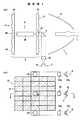
図1(a)は参考例1に係る照明光学系の断面図であり、図1(b)はこの照明光学系を被照明体側(矢印A方向)から見た図であり、図1(b)のB断面図が図1(a)となる。なお、図1(a)、および以下の図3(a)、4(a)、6において、各部材はその断面形状を重点的に記載したものであって、遠方の端面の記載を省略しているものがある。この照明光学系は、主要光源部1、外周補助光源部8、中央補助光源部2、ならびにこれらの光源部からの光束の光量分布均一化を図る第1インテグレータ部4、第2インテグレータ部(不図示)、第3インテグレータ部5を備えている。
【0016】
主要光源部1は、光源11の発光点が放物面鏡よりなるリフレクタ12の焦点に配置されてなり、光源11から出射された光を被照明体側に反射するリフレクタ12の開口部からは、略平行な光束が出射される。この光源11は、発光分布が小さく発光効率の高いものが望ましく、現在では、超高圧水銀灯、メタルハライドランプ、キセノンランプなどの発光管等からなることが一般的である。
【0017】
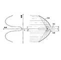
この主要光源部1から出射される光束の、光軸と垂直な断面内における光量分布としては、所定範囲に光強度の弱い部分(以下、光束低密部と称する)が存在する。図2はこの光束低密部を説明するための図である。光源101から放射された白色光は、放物面リフレクタ104により反射されて、放物面リフレクタ104の光軸Xに略平行な光束となって光源部から出射される。図示のとおり、この出射光束の光量分布は一様ではなく、光軸Xの近傍および外周部に光束低密部が存在する。
【0018】
外周部の光束低密部は、発光点108から放射された光を放物面リフレクタ104により反射する場合に原理的に生じるもので、光軸Xに近い部分での反射光量が大きく、周辺に向かうにしたがって反射光量が小さくなっていくことにより生じる。光軸近傍の光束低密部は、実際の光源101が点光源でなく、例えばリフレクタ104の後部に配置された発光管等であるという構造上の理由により生じる。リフレクタ後部に設けられた孔部のために光が反射されない、または発光体そのものの大きさが原因となって光が遮られるためである。発光管を配置するためにリフレクタ最後部に鏡面化されていない範囲があり、この直径をCとすると、光源部から出射される光束の光軸近傍となる中央部に、少なくとも、図2においては光軸に直交する面内で直径Cの範囲に、光がほとんど通過しない空間が存在することになる。
【0019】
また、放物面リフレクタ104から出射される平行光束のさらに外周部も光強度は必ずしも0とはならず、弱い光強度ではあるが、漏れ光等により光が存在する。本発明において「光束低密部」とは、これらをも含む光強度の弱い部分のことである。
【0020】
本発明に係る照明光学系は、リフレクタ104のような凹面鏡リフレクタを備えたこのような光源部から出射される光束の、外周部および中心近傍に存在する光束低密部に着目し、この光源部(主要光源部1)から出射された光束の、外周部の光束低密部に光束を補うように光束を出射する外周補助光源部8、および、中心近傍の光束低密部に光束を補うように光束を出射する中央補助光源部2を備えた構成とされている。
【0021】
図1(a)の断面図に示すとおり、中央補助光源部2は半導体レーザLDからなるレーザ光源31よりなり、コリメータレンズ35により平行光束とされた中央補助光源部2からの光束が偏向ミラー3により偏向されて、主要光源部1から出射された光束の中心近傍の光束低密部に導入される。
【0022】
外周補助光源部8は、図1(b)に示すとおり、半導体レーザLDからなる2つのレーザ光源52a、52bよりなる。光源52a、52bからの光束は、コリメータレンズ53a、53bにより平行光束とされ、図示されない偏向ミラーによりそれぞれ偏向されて、主要光源部1から出射された光束の外周部の光束低密部の、リフレクタ12の光軸に対し互いに略回転対称となる位置に導入される。レーザ光源52a、52bおよびこれらの光源からの光束の光路上の部材は、図1(a)におけるレーザ光源31およびこの光源からの光束の光路上の部材と略同様であって、互いに平行で、図1(a)において紙面手前方向と奥行方向にこれらと重なり合うように配されている。
【0023】
主要光源部1から出射された光束の光束低密部に補助光源部2、8から光束を補うという構成は、光源部全体として光量が増加し照明光学系の明るさを向上させることができる。外周補助光源部8と中央補助光源部2とは、両者を設置することにより一層の光量増加を図ることができるものである。しかし、リフレクタを備えた主要光源部からの光束に対して、外周補助光源部8のみ、または中央補助光源部2のみを配した照明光学系においても、相応の光量増加が可能である。
【0024】
また、外周補助光源部8は、従来一般に用いられるリフレクタを備えた光源部に対し、これを主要光源部1として、その外周部に補助光源部8を追加設置するだけでもよく、設計変更も少なくコンパクトなままで明るさを向上させることができる。また、この外周部の光束低密部に光束を補うために、例えば偏向ミラーなどの部材を配設しても、主要光源部1からの光束の光強度が弱い部分であるので、主要光源部1からの光束を遮ることが少なく、主要光源部1からの光束を効率よく利用することができる。主要光源部1からの光束を若干遮光する場合にも、外周補助光源部8からそれ以上の光量が補われることにより、照明光学系全体としての明るさを向上させることが可能である。
【0025】
なお、外周補助光源部8は、放物面リフレクタ104から出射される平行光束中の外周部の光束低密部、この平行光束のさらに外周部の光束低密部、およびこの両者に光束を補うように光束を出射するものとすることができる。
【0026】
外周補助光源部8としては、少なくとも1つの光源を備えることにより照明光学系の光量増加が可能であるが、複数個の光源を備えることにより、より明るさを増すことができる。さらに望ましくは、図示の照明光学系のように、複数個の光源からの光束が、リフレクタ12の光軸に対し互いに略回転対称となるような位置に導入されることが好ましい。それにより照度分布の均一性を保つことができ、さらに投写型表示装置の照明光学系として用いた場合には、後段の投写光学系のレンズによるケラレが生じたとしてもその悪影響を防止し、色分解ダイクロイックミラーの特性による色ムラを制御することができる。
【0027】
さらに、近年、投写型表示装置の薄型化(リフレクタ光軸を水平配置した場合の高さ方向の小型化)を目的として多く用いられている、出射断面が矩形状の角型リフレクタを用いた場合にも、外周補助光源部8により光量増加を図ることができる。このようなリフレクタは、所定のアスペクト比を有する長方形状の出射断面形状を有するので、照明光学系の瞳位置近傍でも長方形状の光束断面となる。他方、照明光学系の瞳は光軸と直交する断面において円形である。この円直径が長方形形状の短辺と等しいかそれよりも小さい場合には、瞳全体を光束が通過することになるが、これでは瞳の外を通る光束が無駄になってしまう。したがって実際には、瞳の一部に光束が通過しない部分が存在することを容認し、より多くの照明光束が瞳を通過するように構成されることになる。本発明によれば、この、瞳内でありながら主要光源部1からの光束が通過しない部分に光束を補うように、外周補助光源部8を配設することにより、照明光学系全体としての明るさを向上させることができる。
【0028】
なお、上述した角型リフレクタ以外の要因により、瞳内でありながらその外周部に主要光源部1からの光束が通過しない部分が生じる場合にも、この部分に光束を補うように外周補助光源部8を配設することにより、同様の明るさ向上効果を得ることができる。このような部分とは、照明光学系の瞳面と主要光源部から出射された光束による照射面とが、照明光学系の瞳位置で光軸と直交する断面において部分的に互いに重なるよう構成された照明光学系に関し、上記断面において、上記瞳面と上記照射面とが重ならない部分のうち瞳面が照射面より突出する部分である、と規定することもできる。
【0029】
また、中央補助光源部2も、従来一般に用いられるリフレクタを備えた光源部に対し、これを主要光源部1として、設計変更も少なくコンパクトなままで明るさを向上させることができるものである。主要光源部1から出射された光束の中心近傍の光束低密部に中央補助光源部2から光束を補うという構成は、単に光源部全体として光量が増加し照明光学系の明るさ向上に寄与するのみならず、光量分布においても、本来最も光強度を大きくしたい光束の中心近傍の光束低密部の光強度を増強することができることになる。また、この光束低密部に光束を補うために、例えば偏向ミラー3などの部材を配設しても、主要光源部1からの光束の光強度が弱い部分であるので、主要光源部1からの光束をほとんど遮ることなく、主要光源部1からの光束を効率よく利用することができる。
【0030】
なお、中央補助光源部2および外周補助光源部8の光源が半導体レーザ31、52a、52bとされている場合には、この光源は通常、冷却しつつ用いる必要がある。そのため、主要光源部1からの光が直接当たらないところに配置することが好ましく、必要に応じて偏向ミラー3のような導光手段により導入されることが好ましい。
【0031】
また、この照明光学系は上記構成に加え、主要光源部1からの光束の光軸と垂直な断面における光量分布の均一化を図る第1インテグレータ部4、外周補助光源部8からの光束の光軸と垂直な断面における光量分布の均一化を図る第2インテグレータ部(不図示)、および中央補助光源部2からの光束の光軸と垂直な断面における光量分布の均一化を図る第3インテグレータ部5を備えている。なお、以下の説明では、第1〜第3インテグレータ部の作用について「光量分布の均一化」と記載されている場合は、上記断面におけるものとする。
【0032】
図1(a)に示すとおり、主要光源部1から出射された光束は、主要光源部側から順に第2フライアイ15、第1フライアイ16が配設された第1インテグレータ部4により、光量分布の均一化を図られて、照明光束として照明光学系から出射される。すなわち、第2フライアイ15が主要光源部1からの略平行光束を第2フライアイ15のレンズセルの数と同数の部分光束に分割し、第1フライアイ16を構成する各レンズセル近傍に光源11の二次光源像を形成させることにより光量分布の均一化を図る。図1(b)に示すとおり、フライアイ16は、矩形状の輪郭をした微小な凸レンズによるレンズセル18が縦横に複数配列されたものである。図1(b)において、レンズセル18に相当する部分をハッチングにより示している。また、フライアイ15は、フライアイ16の各レンズセル18に各々対応するレンズセル17を備えた形状とされている。第2フライアイ15はレンズセル17の凸面を主要光源部側に向け、第1フライアイ16はレンズセル18の凸面を被照明体側に向けるように配置されている。
【0033】
なお、フライアイ15、16の中央部の、中央補助光源部2からの光束が入射する位置には、レンズセル17、18とは異なる形状の集光レンズ37、38が設けられている。また、不図示であるが、フライアイ15の延長面上の外周補助光源部8からの光束が入射する位置には、それぞれ集光レンズが設けられている。さらに、フライアイ16の延長面上の外周補助光源部8からの光束が入射する位置には、それぞれ集光レンズ55a、55bが設けられている。外周補助光源部8からの光束の光路上のレンズは、上記フライアイ15の延長面上のレンズは集光レンズ37と、また、集光レンズ55a、55bは集光レンズ38と同形状のレンズとされていてもよい。集光レンズ37を備えたフライアイ15、および、集光レンズ38を備えたフライアイ16は、同一形状とすることがコスト上有利である。なお、外周補助光源部8からの光束が入射する位置に設けられる集光レンズは、第1フライアイ16または第2フライアイ15と隣接して配置させてもよいし、これらと一体的に形成することもできる。
【0034】
中央補助光源部2から出射された光束は、第3インテグレータ部5としてのロッドインテグレータ36により、光量分布の均一化を図られる。ロッドインテグレータ36は2枚のフライアイ15、16の間に配設され、中央補助光源部2からの光束は、第2フライアイ15を透過する際に、集光レンズ37の作用により所定の角度をもってロッドインテグレータ36に入射される。そのため、ロッドインテグレータ36の内壁面において複数回反射されて出射され、光量分布が均一化される。
【0035】
また、外周補助光源部8から出射された光束は、図示されない第2インテグレータ部としてのロッドインテグレータにより、光量分布の均一化を図られる。第2インテグレータ部としてのロッドインテグレータは、不図示であるが第3インテグレータ部5のロッドインテグレータ36と略同様であって、図1(a)においてロッドインテグレータ36と互いに平行に、紙面手前方向と奥行方向にロッドインテグレータ36と重なり合うように配されている。外周補助光源部8からの光束は、第2フライアイ15の延長面上の外周補助光源部8からの光束が入射する位置に設けられた集光レンズの作用により、所定の角度をもってこれらのロッドインテグレータに入射される。そのため、各ロッドインテグレータの内壁面において複数回反射されて出射され、光量分布が均一化される。
【0036】
なお、参考例1および以下の説明において、ロッドインテグレータとしては、ガラス製の中実な棒状ロッドプリズムや、内面を反射コートにより鏡面とした中空プリズムや、棒状ロッドプリズムを光束入射側に配置しその光束出射側に中空プリズムを配置して両者を組み合わせた、いわゆるハイブリッド型のインテグレータを用いることができる。ロッドインテグレータに入射した光束は、棒状ロッドプリズムにおいては内壁面において複数回全反射されながら、中空プリズムにおいては内壁面の鏡面で複数回反射されながら、その光束出射端に導かれる。ロッドインテグレータから出射される光束は、ロッドインテグレータの出射端において光束密度が略均一化された光束とされている。投写型表示装置のインテグレータ部として用いる場合には、ロッドインテグレータの出射端と後段のライトバルブとがリレーレンズを介して互いに結像関係(共役関係)となるように構成される。
【0037】
第2インテグレータ部および第3インテグレータ部5から出射された光束は、フライアイ16上の集光レンズ38およびその延長面上の集光レンズ55a、55bにより所望の方向に屈折せしめられる。投写型表示装置に用いる照明光学系としては、外周補助光源部8および中央補助光源部2からの光束が、主要光源部1からの光束と同様に後段のライトバルブ上に重畳されるように屈折させることが好ましい。
【0038】
参考例1においては、外周補助光源部8および中央補助光源部2から出射される光束は、主要光源部1から出射される光束の光束低密部に光束を補うように出射される光束径の小さいものであることを利用し、これら補助光源部8、2から出射される光束の光量分布を均一化するための第2および第3インテグレータ部としては、ロッドインテグレータを用いた簡易な構成としている。そして、このロッドインテグレータの配設位置としては、2枚のフライアイ15、16の間とし、スペースを有効利用しコンパクトな構成を達成している。
【0039】
なお、本発明において、外周補助光源部8または中央補助光源部2から出射される光束が出射された状態で光量分布が略均一となっているような光源とされている場合、例えば、このようなレーザ光源を用いた場合には、外周補助光源部8または中央補助光源部2からの光束はインテグレータにより光量均一化を図る必要がないので、光量均一化を図る手段を省略し、より簡易な構成とすることができる。
【0040】
また、中央補助光源部2が複数の光源からなるように構成し、これら複数の光源からの光束を合成させて主要光源部1からの光束の中心近傍の光束低密部に光束を補うように、この光束中に導入するようにしてもよい。
【0041】
以下、本発明に係る照明光学系の実施例2および参考例3について説明する。なお、各実施例および参考例においては、特に記載のない限り参考例1と同様の構成部分には同一の符号を付しており、既出の事項に関しては詳細な説明を省略している。
【0042】
<実施例2>
本実施例に係る照明光学系の概略構成の断面図を図3(a)に示す。また、図3(b)はこの照明光学系を被照明体側(矢印A方向)から見た図であり、図3(b)のB断面が図3(a)となる。この照明光学系は、参考例1と異なり中央補助光源部は配されていないが、外周補助光源部8により明るくコンパクトな照明光学系とされている。
【0043】
本実施例の主要光源部1の構成は参考例1と同様である。第1インテグレータ部も参考例1と同様に2枚のフライアイ15、16よりなるが、本実施例では中央補助光源部は配されていないので、フライアイ15、16の中央部にもレンズセル17、18が形成されている。
【0044】
本実施例の外周補助光源部8は、リフレクタ12の光軸に対し互いに略回転対称となるように配設された2つの光源を備え、放物面鏡よりなるリフレクタ57a、57bの焦点位置に各々光源56a、56bが配された構成とされている。本発明に係る照明光学系の外周補助光源部8は、レーザ光源に限られるものではなく、本実施例のような凹面鏡リフレクタを用いたものであってもよい。この場合は、外周補助光源部8として低コストで光量の大きいものとすることができる。この外周補助光源部8から出射された光束は光量分布の不均一な略平行光とされているので、光量均一化を図るために光源ごとにフライアイによる第2インテグレータ部9が設けられている。光源側より順に、外周補助光源部8に対応する第2フライアイ58a、58b、および外周補助光源部8に対応する第1フライアイ59a、59bであり、これらはフライアイ16の略延長上となる両面の、外周補助光源部8からの光束が入射する位置に設けられている。
【0045】
図3(b)には、第1フライアイ16の被照明体側の外周部に形成された、外周補助光源部8に対応する第1フライアイ59a、59bが示されている。このフライアイ59a、59bは、レンズセル18とは異なる大きさの矩形状の輪郭をした微小な凸レンズによるレンズセル49が、縦横に複数配列されてなる。また、図3(a)に示されるように、この第1フライアイ59a、59bの外周補助光源部側の面には、各レンズセル49に各々対応するレンズセル48を備えた、外周補助光源部8に対応する第2フライアイ58が形成されている。外周補助光源部8からの略平行光束は、対応する第2フライアイ58a、58bにより各部分光束に分割されて集光され、さらに、対応する第1フライアイ59a、59bにより所望の方向に屈折されて出射される。投写型表示装置に用いる照明光学系としては、外周補助光源部8からの光束が、主要光源部1からの光束と同様に後段のライトバルブ上に重畳されるよう屈折されることが好ましい。
【0046】
なお、第2インテグレータ部9の2面のフライアイ58a、58b、59a、59bは、第1インテグレータ部のフライアイ16の延長上に一体的に形成してもよい。また、第2インテグレータ部9として、本実施例のように一部材の一方の面が第1フライアイ、他方の面が第2フライアイとして作用するものだけでなく、第1フライアイと第2フライアイとが別部材とされた、2枚構成のフライアイを用いることも可能である。この場合、少なくとも一方のフライアイを、第1インテグレータ部の2枚のフライアイ15、16のうち少なくとも一方のフライアイと同一部材上に形成し、部材数を低減し簡易でコンパクトな構成とすることができる。
【0047】
また、本実施例の変更例として、外周補助光源部8に楕円面鏡よりなるリフレクタを用いることも可能である。この場合、第2インテグレータ部9としてロッドインテグレータを用いてもよい。
【0048】
<参考例3>
参考例3に係る照明光学系の概略構成の断面図を図4(a)に示す。また、図4(b)はこの照明光学系を被照明体側(矢印A方向)から見た図であり、図4(b)のB断面が図4(a)となる。この照明光学系も、外周補助光源部8により明るくコンパクトな照明光学系とされている。
【0049】
参考例3の主要光源部1の構成は参考例1と同様である。また、第1インテグレータ部の2枚のフライアイ15、16は実施例2と同様である。また、この参考例3は、第1インテグレータ部の後段に、ランダムな偏光を発生する主要光源部1からの光束を直線偏光に変換するための偏光変換光学系6を備えた照明光学系とされている。投写型表示装置に用いる照明光学系としては、例えば装置のライトバルブが液晶パネルとされている場合など、照明光学系から出射される光は偏光方向が揃えられた略平行光とされていることが好ましい場合があるので、この参考例3によりこのような態様の一例を示す。
【0050】
偏光変換光学系6は、第1インテグレータ部から出射された主要光源部1からの光束の偏光方向を揃えるもので、従来よく知られた、偏光ビームスプリッタアレイ、およびこのアレイの光出射面側に配設され複数のλ/2位相膜21がストライプ状に配設されたλ/2位相板からなるものである。
【0051】
偏光ビームスプリッタアレイはその内部に、偏光分離膜19と反射膜20とが、光軸に対して略45度の角度を有するように交互に形成されている。ランダムな偏光である主要光源部1からの光束は、フライアイ16の対応するレンズセルから入射され、偏光分離膜19により偏光方向の異なるP偏光とS偏光の2種類の偏光に分離される。一方の偏光は偏光分離膜19を透過しプリズム面22から出射される。他方の偏光は偏光分離膜19および隣接する反射膜20で反射されて、最終的には、偏光ビームスプリッタアレイを直進透過した光束とほぼ平行な角度で偏光ビームスプリッタアレイより出射され、λ/2位相膜21を通過する際に、偏光面の回転作用により偏光ビームスプリッタアレイを直進透過した光束と略一致する偏光方向に変換されて出射される。なお、図4(b)において、ハッチング部分はλ/2位相膜21が配された部分である。
【0052】
この参考例3の外周補助光源部8は、リフレクタ12の光軸に対し互いに略回転対称となるように配設された、半導体レーザLDからなる4つのレーザ光源52a〜d(光源52b、52dは不図示)よりなる。ここでは、光源52aからの光束に関して説明するが、光源52b〜dに関してもそれぞれ同様である。光源52aからの光束は、集光レンズ47aの作用により、所定の角度をもって第2インテグレータ部9としてのロッドインテグレータ54aに入射される。そのため、ロッドインテグレータ54aの内壁面において複数回反射されて出射され、光束出射端において光量分布が均一化された状態で出射され、集光レンズ55aにより所望の方向に屈折せしめられる。投写型表示装置に用いる照明光学系としては、外周補助光源部8からの光束が、主要光源部1からの光束と同様に後段のライトバルブ上に重畳されるように屈折させることが好ましい。
【0053】
図示されていないがレーザ光源52b、52dおよびこれらの光源からの光束の光路上の部材は、図4(a)における、レーザ光源52aおよびこの光源からの光束の光路上の部材と略同様であって、互いに平行に配されており、各光源52b、52dからの光束が図4(b)に示された集光レンズ55b、55dに各々入射されるような位置に、紙面手前方向と奥行方向に配されている。
【0054】
なお、外周補助光源部8の光源52a〜dが偏光方向の揃えられた光束を出射するものとされている場合には、この光源からの光の偏光方向を揃えるための偏光変換光学系を配設する必要はなく、構成の簡易化を図ることができる。すなわち、主要光源部1の光源はランダムな偏光を発生し、この光束が偏光変換光学系6により直線偏光に変換されて被照明体の照明を行い、外周補助光源部8は、偏光変換光学系6により直線偏光に変換された主要光源部1からの光束と略一致する偏光方向となるような、偏光方向が揃えられた光束を出射し、この光束は偏光変換をされずに被照明体の照明を行うように構成すればよい。
【0055】
また、外周補助光源部8の光源52a〜dがランダムな偏光を発生するものとされている場合は、この光源からの光の偏光方向を、直線偏光に変換された主要光源部1からの光束と略一致する偏光方向となるように揃えるための偏光変換光学系を、後段に適宜配設することが好ましい。
【0056】
なお、参考例3においても、外周補助光源部8からの光束が入射する位置に設けられる集光レンズ47a〜d、55a〜dは、第1フライアイ16または第2フライアイ15と隣接して配置させてもよいし、これらと一体的に形成することもできる。
【0057】
以上、本発明に係る照明光学系の具体的な例として、参考例1、3および実施例2について説明した。各参考例および実施例とも、主要光源部1から出射された光束の外周部の光束低密部に外周補助光源部から光束を補い、主要光源部と外周補助光源部からの各々の光束の光量分布を均一化させ得る構成とされているので、明るく均一な照明を行ない得るコンパクトな照明光学系とされている。
【0058】
ところで、本発明に係る照明光学系の主要光源部に用いられる光源としては、例えば超高圧水銀灯、メタルハライドランプ、キセノンランプなどがあるが、これらの光源は各々種類により固有の分光分布を有しており、可視光領域において一様な光量分布を持っているわけではない。本発明に係る照明光学系の主用途である投写型表示装置に関しては、明るさの要望以外に、色再現性が良い画像が要求されるが、色再現性を良好とするためには、この光源の分光分布のばらつきが問題となる場合がある。光源によっては、色再現性を良好とするために必要な波長域の光量が不足していたり、また、不必要な波長域の光量が過剰であったりするためである。
【0059】
例えば、図5は超高圧水銀灯の可視領域における波長の分光分布を示す図であり、縦軸が光強度を示すものである。図示のとおりこの光源では、3原色光のうち赤色波長域が、他の色成分に対応する波長域に比べ光量が少なく、その一方、黄色波長域に光強度のピークを有するため、そのままの光源光を使用すると、全体として黄色味を帯びたカラー画像が形成されてしまう。そのため、従来、装置の色再現性を良好とする方策としては、光源から出射された光のうち580nm近辺の波長域の光を取り除いて照明を行っていたが、その分の光量損失は明るさ向上の要望とは反するものとなってしまう。
【0060】
本発明に係る照明光学系によれば、主要光源部から出射された光束の外周部の光束低密部に光束を補うように光束を出射する外周補助光源部を備え、外周補助光源部の光源のうち少なくとも1つの光源から、主要光源部から出射される光束の分光分布において増加させたい波長域に強度ピークを有する光束を出射させるように構成することができる。例えば、主要光源部の発光体が上記超高圧水銀灯とされた場合に、外周補助光源部の光源のうち少なくとも1つの光源から、赤色波長域に強度ピークを有する光束を出射させる構成とすることである。この光源としては、例えば、安価で小型な赤色半導体レーザを用いることができる。このような構成によれば、照明光束全体として赤色波長域の光強度が増加し、従来は色再現性に悪影響を及ぼしていた超高圧水銀灯からの580nm近辺の光も、排除することなく利用できるようになる。この、これまで排除していた光量は、超高圧水銀灯の全光量の20%にも相当し、これ程の光量が増加する効果は高い。
【0061】
主要光源部から出射される光束の分光分布において増加させたい波長域に強度ピークを有する光束を、外周補助光源部から出射させるように構成することにより、単に外周補助光源部からの光量分が増加するのみならず、色再現性のためにこれまで排除していた主要光源部からの光束も色再現性の低下を招くことなく取り込むことができ、明るく色再現性の良いコンパクトな照明光学系を得ることができる。なお、外周補助光源部から出射させる光束の強度ピークは赤色波長域に限られるものではなく、主要光源部の光源の分光分布に応じその波長域を適宜設定することができる。
【0062】
また、中央補助光源部の光源についても、外周補助光源部の光源と同様に、増加させたい波長域に強度ピークを有する光束を出射させるように構成してもよい。また、外周補助光源部および中央補助光源部を構成する各光源の波長域は、全てを同一とする必要はなく、これらの光源のうちの少なくとも1つが、他の光源と異なる波長域に強度ピークを有する光束を出射する構成としてもよい。
【0063】
本発明の照明光学系としては、上述したものに限られるものではなく種々の態様の変更が可能である。例えば、主要光源部において、光源からの光を反射させ前方に出射させる凹面鏡リフレクタとして、楕円面鏡を用いることができる。楕円面鏡よりなるリフレクタの第1焦点に光源を配置した場合、リフレクタの開口部から出射される光束は楕円面鏡の第2焦点に収束されるが、放物面リフレクタの場合と同様の理由により、この第2焦点を中心とした所定角度範囲に、外周光束低密部および中央光束低密部が存在することになる。したがって、外周補助光源部および中央補助光源部を配設して、放物面リフレクタの場合と同様の作用効果を得ることができる。
【0064】
また、主要光源部の光源としては、参考例1、3および実施例2の説明として挙げた発光管タイプのものだけでなく、多くはキセノンランプとして用いられる、リフレクタの後部に陽極が配置されリフレクタの光出射側から陰極が配置されるタイプとされていてもよい。
【0065】
また、主要光源部からの光束の光量均一化を図る第1インテグレータ部は2枚のフライアイによるものに限られず、例えば、ロッドインテグレータを用いることができる。
【0066】
また、外周補助光源部および中央補助光源部は、照明光学系の光量増加、光量分布の均一化、色再現性の適正化(所定の色味を強くしたい、弱くしたい等の場合を含む)等の所期の目的を達成し得る光量を発生させるものとすることが好ましい。
【0067】
また、各フライアイのレンズセルや、各光源部からの光束の光路中に配される各レンズの形状は、適宜設定することができる。外周および中央補助光源部からの光束の光路中の集光レンズが、フライアイのレンズセルと同形状とされていてもよい。
【0068】
なお、付言すれば、本発明に係る照明光学系は、従来多数提案されている、単に総量としての光量を増加させるために複数の光源を備えた照明光学系とは、その目的も作用効果も異なるものである。従来の複数光源を備えた照明光学系は、本発明の主要光源部に相当するような大きさの光源部を複数個配設することにより、総量としての光量を増加させることを目的としている。これらは、本発明のような、リフレクタを備えた光源部から出射された光束の光束低密部に別の光源から光束を補う、という発想を有するものではない。
【0069】
また、前述の投写型表示装置の色再現性の問題を解決するべく、2原色光を発生させる補助光源を備えた照明光学系も既に提案されている(例えば特開2002−174854号公報参照)。しかしこの照明光学系においては、補助光源からの光束は白色光源の光量分布の均一化を図るマルチレンズアレイの一部(望ましくはそのマルチレンズアレイ中の1レンズセル)に入射する構成とされている。本発明に係る照明光学系は、補助光源からの光束に対し各々適当な第2インテグレータ部を備え、外周補助光源部からの光束も光量分布均一化を図り得る構成とされている。
【0070】
次に、本発明に係る投写型表示装置の具体的な実施例として、実施例4について説明する。実施例4においても、特に記載のない限り参考例1、3および実施例2と同様の構成部分には同一の符号を付しており、既出の事項に関しては詳細な説明を省略している。
【0071】
<実施例4>
本実施例に係る投写型表示装置の概略構成を図6に示す。この装置は、上記参考例1に係る照明光学系を用いた装置とされている。なお、この照明光学系の偏光変換光学系6は、参考例3と同様の従来よく知られたものとされている。
【0072】
この装置は、照明光学系からの照明光束により、所定の画像情報に基づいて照明光束の光変調を行なう透過型画像表示素子よりなるライトバルブを照明し、このライトバルブからの画像情報を担持した光束を、投写光学系67を介し投写するものである。照明光束は、第1インテグレータ部4、第2インテグレータ部および第3インテグレータ部5により光量分布が均一化され、偏光変換光学系6により偏光方向が揃えられた状態で、本発明の照明光学系から出射される。そしてこの照明光束は、以下に示すとおり、3原色光に分解され、各色光用の透過型画像表示素子である液晶パネル64a〜cにより光変調されて、これらの投映光束が合成された後、投写光学系67により投写されて、スクリーン(不図示)上にフルカラー画像が結像される。なお、以下に示す第1〜第3色光成分とは、青色、緑色、赤色の3原色光を任意の順に対応させることができる。
【0073】
すなわち、照明光学系から出射された照明光束は、ダイクロイックミラー62a、62bにより色光分解され、それぞれ第1〜第3色光成分用の画像が表示される液晶パネル64a〜cに照射される。ダイクロイックミラー62aは、照明光束を第1色光成分光束と第2、第3色光成分の合成光束とに分離し、ダイクロイックミラー62bは、ダイクロイックミラー62aにより分離された第2、第3色光成分の合成光束を、第2色光成分と第3色光成分とに分離するものである。照明光束の光路上には、偏向のための全反射ミラー63〜dと、集光レンズ61a〜fとが配され、液晶パネル64a〜c上には、主要光源部1、外周補助光源部、および中央補助光源部2からの光束が重畳される。液晶パネル64a〜cを透過し、所定の画像情報に基づいて光変調された投映光束である第1〜第3色光成分光束は、第1色光成分を反射するダイクロイック膜65aと第3色光成分を反射するダイクロイック膜65bとを内部に有する、クロスプリズム66により合成される。
【0074】
本実施例によれば、コンパクトでありながら、照明効率が高く明るく均一な照明を行ない得る投写型表示装置を得ることができる。
【0075】
なお、本発明の投写型表示装置としてはこの実施例のものに限られず、種々の態様の変更が可能である。例えば、本発明の投写型表示装置としては、本発明の実施例2の照明光学系を用いることができる。
【0076】
また、本発明の投写型表示装置においてライトバルブは実施例のものに限られない。例えば、デジタル・マイクロミラー・デバイス(DMD)や、反射型画像表示素子よりなるライトバルブを備えた投写型表示装置にも、本発明の照明光学系を適用することができる。また、本発明の投写型表示装置は必ずしもカラー画像表示装置に限られず、モノクロ画像表示装置とされていてもよい。
【0077】
また、前述したとおり、本発明に係る照明光学系は、主要光源部から出射される光束の分光分布において増加させたい波長域に強度ピークを有する光束を、外周補助光源部および/または中央補助光源部を構成する複数の光源のうち少なくとも1つの光源から出射させるように構成することができる。例えばこの場合のように、補助光源部を構成する光源のうち少なくとも1つの光源からの光束が、白色光でなく特定の波長域に光強度が偏っている場合には、補助光源部を構成する複数の光源のうち少なくとも1つの光源からの光束は、照明光束を色光分解し各色光ごとに各々ライトバルブにより画像情報を担持させた後に色合成を行なう構成の装置の、複数のライトバルブのうち一部のライトバルブのみを照明するように構成してもよい。例えば、主要光源部が白色光を出射し、補助光源部のうち少なくとも1つの光源が赤色半導体レーザとされている場合、この光源からの光は赤色成分用のライトバルブのみを照明するように構成されていてもよい。
【0078】
【発明の効果】
以上に説明したように、本発明に係る照明光学系およびこれを用いた投写型表示装置によれば、光源とリフレクタよりなる主要光源部から出射された光束の、外周部の光束低密部に光束を補うように光束を出射する外周補助光源部を備え、主要光源部と外周補助光源部からの各々の光束の光量分布を均一化させ得る構成とされていることにより、コンパクトでありながら、照明効率が高く、明るく均一な照明を行ない得る照明光学系およびこれを用いた投写型表示装置を得ることができる。
【図面の簡単な説明】
【図1】 本発明の参考例1に係る照明光学系の概略構成図
【図2】 放物面リフレクタによる反射光の強度分布を示す図
【図3】 本発明の実施例2に係る照明光学系の概略構成図
【図4】 本発明の参考例3に係る照明光学系の概略構成図
【図5】 超高圧水銀灯の可視領域における波長の分光分布図
【図6】 本発明の実施例4に係る投写型表示装置の概略構成図
【符号の説明】
1 主要光源部
2 中央補助光源部
3 偏向ミラー
4 第1インテグレータ部
5 第3インテグレータ部
6 偏光変換光学系
7、66 クロスプリズム
8 外周補助光源部
9 第2インテグレータ部
11、56 光源
12、57、104 放物面リフレクタ
15 第2フライアイ
16 第1フライアイ
17、18、48、49 レンズセル
19 偏光分離膜
20 反射膜
21 λ/2位相膜
22 プリズム面
31、52 半導体レーザ
35、53 コリメータレンズ
36 ロッドインテグレータ
37、38、47、55、61 集光レンズ
58 外周補助光源部に対応する第2フライアイ
59 外周補助光源部に対応する第1フライアイ
62 ダイクロイックミラー
63 全反射ミラー
64 透過型液晶パネル
65 ダイクロイック膜
67 投写光学系
101 発光管
108 発光点[0001]
BACKGROUND OF THE INVENTION
The present invention relates to an illumination optical system that illuminates an object to be illuminated using a light source unit that includes a light emitter and a reflector, and in particular, modulates an illumination light beam with a light valve and uses the projected light beam to image an image on a screen. The present invention relates to an illumination optical system suitable for a projection display device that performs enlarged projection, and a projection display device using the illumination optical system.
[0002]
[Prior art]
In recent years, bright projection display devices have been developed so that projection display devices can be used without problems even in projection in a bright place. As an element that greatly contributes to the improvement of brightness, along with the light valve, development of an illumination optical system is underway. For example, there is a configuration in which the amount of light is increased by an illumination optical system including a plurality of light source units as described in Patent Document 1.
[0003]
[Patent Document 1]
Japanese Patent Laid-Open No. 2001-21996
[0004]
[Problems to be solved by the invention]
Many methods have been proposed in the past for improving the brightness by the construction of an illumination optical system that uses many bright light source sections. Among them, as a light source unit that is advantageous in terms of cost and is bright, a light source unit including a reflector is often used. However, an illumination optical system using a large number of light sources that are equally bright needs to be provided with a means for synthesizing these light sources and the light beams from these light sources, and therefore cannot be increased in size.
[0005]
Such a configuration is also effective when the highest priority is to increase the amount of light emitted from the illumination optical system as much as possible. On the other hand, the light source unit equipped with a conventional reflector is improved. There is also a desire to improve the brightness as much as possible, with a small change in configuration, a compact size of the illumination optical system. If the configuration of a light source unit having a conventional reflector and the illumination optical system and projection display device corresponding to the light source unit can be used with few changes, it is advantageous in terms of cost.
[0006]
The present invention has been made in view of such circumstances, and pays attention to the light amount distribution of a light beam emitted from a light source unit composed of a light source and a reflector, and makes a major design change to this type of light source unit. An object of the present invention is to provide an illumination optical system that is compact and has high illumination efficiency and can perform bright and uniform illumination, and a projection display device using the illumination optical system.
[0007]
[Means for Solving the Problems]
A first illumination optical system according to the present invention includes a main light source unit including a light emitter and a reflector that reflects light emitted from the light emitter toward the object to be illuminated, and uniformizing the amount of light from the main light source unit. A main integrator unit that emits a light beam so as to supplement the light flux in a low-density part of the outer peripheral part of the light beam emitted from the main light source unit, and a light amount of the light beam from the outer peripheral light source unit An illumination optical system provided with a peripheral auxiliary integrator unit for homogenization,
The pupil surface of the illumination optical system and the irradiation surface by the light beam emitted from the main light source unit are configured to partially overlap each other in a cross section orthogonal to the optical axis at the pupil position of the illumination optical system. The outer peripheral auxiliary light source unit that emits a light beam so that the pupil surface of the portion where the pupil surface and the irradiation surface do not overlap each other protrudes from the irradiation surface.,
The outer peripheral auxiliary integrator part is composed of a fly eye separate from the main integrator part.It is characterized byThe
[0008]
Here, the terms “main integrator part” and “outer peripheral integrator part” are functionally expressed, and the actual form is not limited to the case where they are separated, and is integrated. It is also included when it is said. Moreover, the case where these two integrator parts are made common is also included.
[0011]
Further, it is preferable that the outer peripheral auxiliary light source unit includes a plurality of light sources. It is more preferable that the outer peripheral auxiliary light source unit includes a plurality of light sources that emit light beams at positions where the light flux density portion of the outer peripheral portion is substantially rotationally symmetric with respect to the optical axis of the reflector. .
[0012]
The reflector may be a rectangular reflector that emits a light beam having a substantially rectangular shape in a cross section orthogonal to the optical axis.
In addition, the reflector is preferably a parabolic mirror.Yes.
[0013]
A projection display apparatus according to the present invention includes any one of the illumination optical systems described above, and illuminates at least one light valve that performs light modulation of the illumination light beam based on predetermined image information with the light beam from the illumination optical system. The light beam carrying image information from the light valve is projected through a projection optical system.
[0014]
DETAILED DESCRIPTION OF THE INVENTION
Embodiments of the present inventionReference examples andImplementationFor exampleThe illumination optical system will be described as an example.
[0015]
<referenceExample 1>
FIG. 1 (a)Reference example 1FIG. 1B is a view of the illumination optical system as viewed from the illuminated object side (in the direction of arrow A). FIG. 1B is a cross-sectional view of FIG. a). In FIG. 1 (a) and FIGS. 3 (a), 4 (a), and 6 below, each member is described with a focus on its cross-sectional shape, and the description of the far end face is omitted. There is something that is. The illumination optical system includes a main light source unit 1, an outer peripheral auxiliary
[0016]
The main light source unit 1 is configured such that the light emitting point of the
[0017]
As a light amount distribution in a cross section perpendicular to the optical axis of the light beam emitted from the main light source unit 1, a portion having a low light intensity (hereinafter referred to as a light beam low-density portion) exists within a predetermined range. FIG. 2 is a view for explaining the light flux density portion. The white light emitted from the
[0018]
The light flux density portion in the outer peripheral portion is generated in principle when the light emitted from the
[0019]
Further, the light intensity at the outer peripheral portion of the parallel light beam emitted from the
[0020]
The illumination optical system according to the present invention pays attention to the light flux density portion existing near the outer peripheral portion and the center of the light flux emitted from such a light source portion having a concave mirror reflector such as the
[0021]
As shown in the cross-sectional view of FIG. 1A, the central auxiliary
[0022]
As shown in FIG. 1B, the outer peripheral auxiliary
[0023]
The configuration in which the light flux from the auxiliary
[0024]
Further, the outer peripheral auxiliary
[0025]
The outer peripheral auxiliary
[0026]
The outer peripheral auxiliary
[0027]
Furthermore, in recent years, when a rectangular reflector with a rectangular emission cross section is used, which is often used for the purpose of thinning a projection display device (miniaturization in the height direction when the reflector optical axis is horizontally arranged). In addition, the light quantity can be increased by the outer peripheral auxiliary
[0028]
In addition, even when there is a portion where the light beam from the main light source unit 1 does not pass through the outer peripheral portion of the pupil due to factors other than the above-described rectangular reflector, the outer peripheral auxiliary light source portion so as to supplement the light flux in this portion. By arranging 8, the same brightness improvement effect can be obtained. Such a portion is configured such that the pupil plane of the illumination optical system and the irradiation surface by the light beam emitted from the main light source part partially overlap each other in a cross section orthogonal to the optical axis at the pupil position of the illumination optical system. Regarding the illumination optical system, in the cross section, it can also be defined that the pupil surface is a portion protruding from the irradiation surface among the portions where the pupil surface and the irradiation surface do not overlap.
[0029]
Further, the central auxiliary
[0030]
When the light sources of the central auxiliary
[0031]
In addition to the above-described configuration, the illumination optical system includes a
[0032]
As shown in FIG. 1A, the luminous flux emitted from the main light source unit 1 is emitted by the
[0033]
Note that condensing
[0034]
The light flux emitted from the central auxiliary
[0035]
Further, the light flux emitted from the outer peripheral auxiliary
[0036]
In addition,Reference example 1In the following description, as a rod integrator, a solid rod-shaped rod prism made of glass, a hollow prism whose inner surface is a mirror surface by a reflective coating, or a rod-shaped rod prism is arranged on the light beam incident side and hollow on the light beam output side. A so-called hybrid integrator in which prisms are arranged and combined with each other can be used. The light beam incident on the rod integrator is guided to the light beam output end of the rod-shaped rod prism while being totally reflected a plurality of times on the inner wall surface and reflected by the mirror surface of the inner wall surface a plurality of times on the hollow prism. The light beam emitted from the rod integrator is a light beam having a substantially uniform light beam density at the emission end of the rod integrator. When used as an integrator section of a projection display device, the output end of the rod integrator and the subsequent light valve are configured so as to form an imaging relationship (conjugate relationship) with each other via a relay lens.
[0037]
The light beams emitted from the
[0038]
Reference example 1, The luminous fluxes emitted from the outer peripheral auxiliary
[0039]
In the present invention, when the light source is such that the light amount distribution is substantially uniform in a state where the light beam emitted from the outer peripheral auxiliary
[0040]
Further, the central auxiliary
[0041]
Hereinafter, Example 2 of the illumination optical system according to the present invention andReference example3 will be described. Each exampleAnd reference examplesUnless otherwise statedreferenceThe same components as those in Example 1 are denoted by the same reference numerals, and detailed description of the matters already described is omitted.
[0042]
<Example 2>
FIG. 3A shows a cross-sectional view of a schematic configuration of the illumination optical system according to the present embodiment. FIG. 3B is a view of the illumination optical system as seen from the illuminated object side (in the direction of arrow A), and a cross section B in FIG. 3B is FIG. 3A. This illumination optical systemreferenceUnlike Example 1, the central auxiliary light source unit is not arranged, but the outer peripheral auxiliary
[0043]
The configuration of the main light source unit 1 of this embodiment is as follows.referenceSimilar to Example 1. The first integrator sectionreferenceAlthough it consists of two fly
[0044]
The outer peripheral auxiliary
[0045]
FIG. 3B shows the
[0046]
The two fly
[0047]
Further, as a modification of the present embodiment, a reflector made of an ellipsoidal mirror can be used for the outer peripheral auxiliary
[0048]
<
Reference example 3FIG. 4A is a cross-sectional view of the schematic configuration of the illumination optical system according to FIG. FIG. 4B is a view of the illumination optical system as seen from the illuminated object side (in the direction of arrow A), and the B cross section of FIG. 4B is FIG. 4A. This illumination optical system is also a bright and compact illumination optical system by the outer peripheral auxiliary
[0049]
Reference example 3The configuration of the main light source unit 1 isreferenceSimilar to Example 1. The two fly
[0050]
The polarization conversion optical system 6 aligns the polarization direction of the light beam from the main light source unit 1 emitted from the first integrator unit, and is well known in the art in the polarization beam splitter array and the light emission surface side of this array. A plurality of λ / 2
[0051]
In the polarization beam splitter array, the
[0052]
This reference example 3The outer peripheral auxiliary
[0053]
Although not shown, the
[0054]
When the
[0055]
When the
[0056]
In addition,Reference example 3Also, the
[0057]
Specific examples of the illumination optical system according to the present invention have been described above.ExampleAsReference Examples 1, 3 andExample2Explained. eachReference examples andIn both the embodiments, the light flux from the outer peripheral auxiliary light source unit is supplemented to the low-density portion of the outer peripheral portion of the light beam emitted from the main light source unit 1, and the light quantity distribution of each light beam from the main light source unit and the outer peripheral auxiliary light source unit is made uniform. Therefore, it is a compact illumination optical system that can perform bright and uniform illumination.
[0058]
By the way, examples of the light source used in the main light source unit of the illumination optical system according to the present invention include an ultra-high pressure mercury lamp, a metal halide lamp, and a xenon lamp. These light sources each have a specific spectral distribution depending on the type. Therefore, it does not have a uniform light amount distribution in the visible light region. For the projection display device that is the main application of the illumination optical system according to the present invention, an image with good color reproducibility is required in addition to the request for brightness. Variations in the spectral distribution of the light source may be a problem. This is because, depending on the light source, the amount of light in the wavelength range necessary for good color reproducibility is insufficient, or the amount of light in the unnecessary wavelength range is excessive.
[0059]
For example, FIG. 5 is a diagram showing the spectral distribution of wavelengths in the visible region of an ultrahigh pressure mercury lamp, and the vertical axis shows the light intensity. As shown in the figure, in this light source, the red wavelength range of the three primary color lights has a smaller amount of light than the wavelength range corresponding to the other color components, while the yellow wavelength range has a light intensity peak. When light is used, a color image having a yellowish color as a whole is formed. Therefore, conventionally, as a measure for improving the color reproducibility of the apparatus, illumination was performed by removing light in the wavelength range near 580 nm from the light emitted from the light source. It becomes contrary to the demand for improvement.
[0060]
According to the illumination optical system according to the present invention, the light source of the outer peripheral auxiliary light source unit includes the outer peripheral auxiliary light source unit that emits the light beam so as to supplement the light beam in the low-density part of the outer peripheral part of the light beam emitted from the main light source unit. Of these, at least one light source can be configured to emit a light beam having an intensity peak in a wavelength region to be increased in the spectral distribution of the light beam emitted from the main light source unit. For example, when the illuminant of the main light source unit is the ultra-high pressure mercury lamp, a light beam having an intensity peak in the red wavelength region is emitted from at least one of the light sources of the outer peripheral auxiliary light source unit. is there. As this light source, for example, an inexpensive and small red semiconductor laser can be used. According to such a configuration, the light intensity in the red wavelength region increases as a whole of the illumination light beam, and light in the vicinity of 580 nm from an ultrahigh pressure mercury lamp that has been adversely affected by color reproducibility can be used without being excluded. It becomes like this. The amount of light that has been excluded so far corresponds to 20% of the total amount of light of the ultra high pressure mercury lamp, and the effect of increasing this amount of light is high.
[0061]
By configuring the luminous flux having an intensity peak in the wavelength range to be increased in the spectral distribution of the luminous flux emitted from the main light source unit to be emitted from the peripheral auxiliary light source unit, the amount of light from the peripheral auxiliary light source unit simply increases. In addition, it is possible to capture the luminous flux from the main light source part that has been excluded so far for color reproducibility without incurring a decrease in color reproducibility, and a bright and compact illumination optical system with good color reproducibility. Obtainable. The intensity peak of the light beam emitted from the outer peripheral auxiliary light source unit is not limited to the red wavelength region, and the wavelength region can be appropriately set according to the spectral distribution of the light source of the main light source unit.
[0062]
Further, the light source of the central auxiliary light source unit may be configured to emit a light beam having an intensity peak in a wavelength region to be increased, similarly to the light source of the outer peripheral auxiliary light source unit. Further, the wavelength ranges of the respective light sources constituting the outer peripheral auxiliary light source unit and the central auxiliary light source unit need not be the same, and at least one of these light sources has an intensity peak in a wavelength range different from the other light sources. It is good also as a structure which radiate | emits the light beam which has.
[0063]
The illumination optical system of the present invention is not limited to the one described above, and various modifications can be made. For example, an ellipsoidal mirror can be used as a concave mirror reflector that reflects light from the light source and emits it forward in the main light source unit. When the light source is arranged at the first focal point of the reflector made of the ellipsoidal mirror, the light beam emitted from the opening of the reflector is converged to the second focal point of the ellipsoidal mirror. The reason is the same as in the case of the parabolic reflector. Thus, the outer peripheral light flux density portion and the central light flux density portion are present in a predetermined angle range centered on the second focal point. Therefore, by providing the outer peripheral auxiliary light source unit and the central auxiliary light source unit, it is possible to obtain the same operational effects as in the case of the parabolic reflector.
[0064]
In addition, as the light source of the main light source unit,Reference Examples 1, 3 andExample2In addition to the arc tube type mentioned in the description, the anode may be arranged at the rear of the reflector and used as a xenon lamp, and the cathode may be arranged from the light emission side of the reflector.
[0065]
Further, the first integrator unit for making the light amount of the light flux from the main light source unit uniform is not limited to that using two fly eyes, and for example, a rod integrator can be used.
[0066]
In addition, the peripheral auxiliary light source unit and the central auxiliary light source unit increase the light quantity of the illumination optical system, make the light quantity distribution uniform, and optimize the color reproducibility (including the case where it is desired to strengthen or weaken a predetermined color). It is preferable to generate an amount of light that can achieve the intended purpose.
[0067]
Moreover, the shape of each lens arranged in the optical path of the lens cell of each fly eye and the light beam from each light source unit can be set as appropriate. The condensing lens in the optical path of the light beam from the outer periphery and the central auxiliary light source unit may have the same shape as the fly-eye lens cell.
[0068]
In addition, the illumination optical system according to the present invention has a number of conventionally proposed illumination optical systems simply having a plurality of light sources in order to increase the light amount as a total amount. Is different. A conventional illumination optical system including a plurality of light sources is intended to increase the amount of light as a total amount by disposing a plurality of light source portions having a size corresponding to the main light source portion of the present invention. These do not have the idea of supplementing the light beam from another light source to the light beam low density portion of the light beam emitted from the light source unit including the reflector as in the present invention.
[0069]
Further, in order to solve the problem of color reproducibility of the projection display device described above, an illumination optical system including an auxiliary light source that generates two primary color lights has already been proposed (see, for example, JP-A-2002-174854). . However, in this illumination optical system, the light beam from the auxiliary light source is configured to be incident on a part of a multi-lens array (preferably one lens cell in the multi-lens array) for uniformizing the light amount distribution of the white light source. Yes. The illumination optical system according to the present invention includes an appropriate second integrator unit for each light beam from the auxiliary light source, and the light beam from the outer peripheral auxiliary light source unit can also achieve uniform light quantity distribution.
[0070]
Next, Example 4 will be described as a specific example of the projection display apparatus according to the present invention. Also in Example 4, unless otherwise notedReference Examples 1, 3 andExample2The same reference numerals are given to the same components as those in FIG. 1, and detailed description of the matters already described is omitted.
[0071]
<Example 4>
FIG. 6 shows a schematic configuration of the projection display apparatus according to the present embodiment. This deviceOnRecordreferenceThe apparatus uses the illumination optical system according to Example 1. The polarization conversion optical system 6 of this illumination optical system isreferenceIt is assumed to be well known in the same manner as in Example 3.
[0072]
This apparatus illuminates a light valve composed of a transmissive image display element that performs light modulation of an illumination light beam based on predetermined image information with an illumination light beam from an illumination optical system, and carries image information from the light valve. The light beam is projected through the projection
[0073]
That is, the illumination light beam emitted from the illumination optical system is subjected to color light decomposition by the
[0074]
According to this exampleIfIn addition, it is possible to obtain a projection display apparatus that can perform bright and uniform illumination with high illumination efficiency.
[0075]
The projection display device of the present invention is not limited to this embodiment, and various modifications can be made. For example, the projection display device of the present invention includes the present invention.Example 2Illumination opticsForCan be.
[0076]
In the projection display device of the present invention, the light valve is not limited to that of the embodiment. For example, the illumination optical system of the present invention can also be applied to a projection display device including a digital micromirror device (DMD) or a light valve made of a reflective image display element. The projection display device of the present invention is not necessarily limited to a color image display device, and may be a monochrome image display device.
[0077]
In addition, as described above, the illumination optical system according to the present invention uses a light beam having an intensity peak in a wavelength range desired to be increased in a spectral distribution of a light beam emitted from the main light source unit as an outer peripheral auxiliary light source unit and / or a central auxiliary light source. It can comprise so that it may radiate | emit from at least 1 light source among the several light sources which comprise a part. For example, as in this case, when the light intensity from at least one of the light sources constituting the auxiliary light source unit is not white light but the light intensity is biased to a specific wavelength range, the auxiliary light source unit is configured. Among the plurality of light valves, the light beam from at least one light source among the plurality of light sources is composed of the apparatus configured to perform color composition after the illumination light beam is color-separated and image information is carried for each color light by each light valve. You may comprise so that only some light valves may be illuminated. For example, when the main light source emits white light and at least one of the auxiliary light sources is a red semiconductor laser, the light from this light source is configured to illuminate only the red component light valve. May be.
[0078]
【The invention's effect】
As described above, according to the illumination optical system and the projection display apparatus using the illumination optical system according to the present invention, the light flux emitted from the main light source portion composed of the light source and the reflector, It is equipped with an outer peripheral auxiliary light source unit that emits a light beam so as to supplement the light beam, and is configured to be able to uniformize the light quantity distribution of each light beam from the main light source unit and the outer peripheral auxiliary light source unit, while being compact, An illumination optical system having high illumination efficiency and capable of performing bright and uniform illumination and a projection display device using the illumination optical system can be obtained.
[Brief description of the drawings]
FIG. 1 of the present inventionreferenceSchematic configuration diagram of illumination optical system according to Example 1
FIG. 2 is a diagram showing the intensity distribution of reflected light from a parabolic reflector.
FIG. 3 is a schematic configuration diagram of an illumination optical system according to a second embodiment of the present invention.
FIG. 4 of the present inventionreferenceSchematic configuration diagram of illumination optical system according to Example 3
Fig. 5 Spectral distribution of wavelength in the visible region of ultra high pressure mercury lamp
FIG. 6 is a schematic configuration diagram of a projection display apparatus according to
[Explanation of symbols]
1 Main light source
2 Central auxiliary light source
3 Deflection mirror
4 First integrator section
5 Third integrator section
6 Polarization conversion optical system
7, 66 Cross prism
8 Peripheral auxiliary light source
9 Second integrator section
11, 56 Light source
12, 57, 104 Parabolic reflector
15 Second Fly Eye
16 First fly eye
17, 18, 48, 49 Lens cell
19 Polarized light separation membrane
20 Reflective film
21 λ / 2 phase film
22 Prism surface
31, 52 Semiconductor laser
35, 53 Collimator lens
36 Rod Integrator
37, 38, 47, 55, 61 Condensing lens
58 Second fly's eye corresponding to the outer peripheral auxiliary light source
59 First fly eye corresponding to the outer peripheral auxiliary light source
62 Dichroic Mirror
63 Total reflection mirror
64 transmissive LCD panel
65 Dichroic membrane
67 Projection optics
101 arc tube
108 luminous points
Claims (6)
Translated fromJapanese該照明光学系の瞳面と前記主要光源部から出射された光束による照射面とが、前記照明光学系の瞳位置で光軸と直交する断面において部分的に互いに重なるよう構成され、該断面において、前記瞳面と前記照射面とが重ならない部分のうち該瞳面が該照射面より突出する部分に光束を補うように光束を出射する前記外周補助光源部を備え、
該外周補助インテグレータ部は、前記主要インテグレータ部とは別体のフライアイから構成されていることを特徴とする照明光学系。A main light source unit including a light emitter and a reflector that reflects the light emitted from the light emitter toward the illuminated body, a main integrator unit for uniformizing the amount of light from the main light source unit, and the main light source unit An outer peripheral auxiliary light source unit that emits a light beam so as to supplement the light flux in the outer peripheral portion of the emitted light beam, and an outer peripheral auxiliary integrator unit that equalizes the amount of light from the outer peripheral auxiliary light source unit An illumination optical system,
The pupil plane of the illumination optical system and the irradiation surface by the light beam emitted from the main light source unit are configured to partially overlap each other in a cross section orthogonal to the optical axis at the pupil position of the illumination optical system. The outer peripheral auxiliary light source unit that emits a light beam so as to supplement the light beam in a portion where the pupil surface protrudes from the irradiation surface among the portions where the pupil surface and the irradiation surface do not overlap,
2. The illumination optical systemaccording to claim 1, wherein the outer peripheral auxiliary integrator unit is composed of a fly eye separate from the main integrator unit .
Priority Applications (1)
| Application Number | Priority Date | Filing Date | Title |
|---|---|---|---|
| JP2002380427AJP4497507B2 (en) | 2002-12-27 | 2002-12-27 | Illumination optical system and projection display device using the same |
Applications Claiming Priority (1)
| Application Number | Priority Date | Filing Date | Title |
|---|---|---|---|
| JP2002380427AJP4497507B2 (en) | 2002-12-27 | 2002-12-27 | Illumination optical system and projection display device using the same |
Publications (2)
| Publication Number | Publication Date |
|---|---|
| JP2004212529A JP2004212529A (en) | 2004-07-29 |
| JP4497507B2true JP4497507B2 (en) | 2010-07-07 |
Family
ID=32816655
Family Applications (1)
| Application Number | Title | Priority Date | Filing Date |
|---|---|---|---|
| JP2002380427AExpired - Fee RelatedJP4497507B2 (en) | 2002-12-27 | 2002-12-27 | Illumination optical system and projection display device using the same |
Country Status (1)
| Country | Link |
|---|---|
| JP (1) | JP4497507B2 (en) |
Families Citing this family (3)
| Publication number | Priority date | Publication date | Assignee | Title |
|---|---|---|---|---|
| EP2185973A2 (en)* | 2007-08-28 | 2010-05-19 | Koninklijke Philips Electronics N.V. | A front projector |
| JP2018060223A (en)* | 2017-12-15 | 2018-04-12 | カシオ計算機株式会社 | Light source device and projector |
| JP7020315B2 (en)* | 2018-06-20 | 2022-02-16 | セイコーエプソン株式会社 | Light source device and projector |
Family Cites Families (10)
| Publication number | Priority date | Publication date | Assignee | Title |
|---|---|---|---|---|
| JPH04104241A (en)* | 1990-08-24 | 1992-04-06 | Seiko Epson Corp | Lighting light source device |
| JPH07209748A (en)* | 1993-12-30 | 1995-08-11 | Texas Instr Inc <Ti> | Light source device |
| JPH0886979A (en)* | 1994-09-20 | 1996-04-02 | Nikon Corp | Polarized illumination device |
| JP3614294B2 (en)* | 1998-03-09 | 2005-01-26 | 富士通株式会社 | Light intensity conversion element, optical device, and information storage device |
| JP3370612B2 (en)* | 1998-09-14 | 2003-01-27 | 富士通株式会社 | Light intensity conversion element, collimating lens, objective lens, and optical device |
| JP2000305040A (en)* | 1999-04-19 | 2000-11-02 | Toshiba Corp | Projection display device |
| JP3366281B2 (en)* | 1999-05-13 | 2003-01-14 | エヌイーシービューテクノロジー株式会社 | Projector device |
| US6733139B2 (en)* | 2000-06-05 | 2004-05-11 | Hewlett-Packard Development Company, L.P. | Projector with narrow-spectrum light source to complement broad-spectrum light source |
| JP2002174854A (en)* | 2000-12-08 | 2002-06-21 | Hitachi Ltd | Projection optical device and projection type image display device using the same |
| JP2003255465A (en)* | 2002-02-28 | 2003-09-10 | Toshiba Corp | Illumination device and projection display device using the same |
- 2002
- 2002-12-27JPJP2002380427Apatent/JP4497507B2/ennot_activeExpired - Fee Related
Also Published As
| Publication number | Publication date |
|---|---|
| JP2004212529A (en) | 2004-07-29 |
Similar Documents
| Publication | Publication Date | Title |
|---|---|---|
| US8840251B2 (en) | Light collecting optical system and projection-type image display apparatus | |
| CN101625104B (en) | Illumination system, projection-type display apparatus, and optical integrator | |
| JP2007294337A (en) | Lighting device and projector | |
| JP2004524581A (en) | Projector display device | |
| CN114563907B (en) | Light source device, image projection device, and light source optical system | |
| JP4420087B2 (en) | Lighting device and projector | |
| JP2019159287A (en) | Illumination optical unit | |
| US7150535B2 (en) | Lighting device and projector equipped with the same | |
| JPH11316353A (en) | Projection type display device | |
| JPH11281914A (en) | Illuminating optical system and projector device using the system | |
| JP4211969B2 (en) | Illumination optical system and projection display device using the same | |
| JP4497507B2 (en) | Illumination optical system and projection display device using the same | |
| JP4109958B2 (en) | Illumination optical system and projection display device using the same | |
| JP2010026260A (en) | Lighting optical device and projection type display device | |
| JP5097042B2 (en) | Illumination optical device and projection display device using the same | |
| JP2023131646A (en) | Light source device and display device | |
| JPH11311762A (en) | Lighting device for LCD projector | |
| JP2004226460A (en) | Illumination optical system and projection display device using the same | |
| JP4244290B2 (en) | Illumination optical system and projection display device using the same | |
| JP2002244199A (en) | Light source device, illumination optical system, and projector | |
| JP2008234897A (en) | Light source device and projector | |
| JP5035879B2 (en) | Illumination optical system and projection display device | |
| JP4487484B2 (en) | LIGHTING DEVICE AND PROJECTOR HAVING THE SAME | |
| JP2003043580A (en) | Lamp, polarization conversion optical system and image display device | |
| JP4420428B2 (en) | Polarized illumination optical system and projection display device using the same |
Legal Events
| Date | Code | Title | Description |
|---|---|---|---|
| A621 | Written request for application examination | Free format text:JAPANESE INTERMEDIATE CODE: A621 Effective date:20051121 | |
| A977 | Report on retrieval | Free format text:JAPANESE INTERMEDIATE CODE: A971007 Effective date:20071211 | |
| A131 | Notification of reasons for refusal | Free format text:JAPANESE INTERMEDIATE CODE: A131 Effective date:20080110 | |
| A521 | Request for written amendment filed | Free format text:JAPANESE INTERMEDIATE CODE: A523 Effective date:20080310 | |
| A02 | Decision of refusal | Free format text:JAPANESE INTERMEDIATE CODE: A02 Effective date:20091001 | |
| A521 | Request for written amendment filed | Free format text:JAPANESE INTERMEDIATE CODE: A523 Effective date:20091221 | |
| A911 | Transfer to examiner for re-examination before appeal (zenchi) | Free format text:JAPANESE INTERMEDIATE CODE: A911 Effective date:20100106 | |
| TRDD | Decision of grant or rejection written | ||
| A01 | Written decision to grant a patent or to grant a registration (utility model) | Free format text:JAPANESE INTERMEDIATE CODE: A01 Effective date:20100407 | |
| A01 | Written decision to grant a patent or to grant a registration (utility model) | Free format text:JAPANESE INTERMEDIATE CODE: A01 | |
| A61 | First payment of annual fees (during grant procedure) | Free format text:JAPANESE INTERMEDIATE CODE: A61 Effective date:20100412 | |
| FPAY | Renewal fee payment (event date is renewal date of database) | Free format text:PAYMENT UNTIL: 20130423 Year of fee payment:3 | |
| R150 | Certificate of patent or registration of utility model | Free format text:JAPANESE INTERMEDIATE CODE: R150 | |
| FPAY | Renewal fee payment (event date is renewal date of database) | Free format text:PAYMENT UNTIL: 20130423 Year of fee payment:3 | |
| S111 | Request for change of ownership or part of ownership | Free format text:JAPANESE INTERMEDIATE CODE: R313113 | |
| R350 | Written notification of registration of transfer | Free format text:JAPANESE INTERMEDIATE CODE: R350 | |
| FPAY | Renewal fee payment (event date is renewal date of database) | Free format text:PAYMENT UNTIL: 20130423 Year of fee payment:3 | |
| FPAY | Renewal fee payment (event date is renewal date of database) | Free format text:PAYMENT UNTIL: 20130423 Year of fee payment:3 | |
| FPAY | Renewal fee payment (event date is renewal date of database) | Free format text:PAYMENT UNTIL: 20140423 Year of fee payment:4 | |
| LAPS | Cancellation because of no payment of annual fees |