Movatterモバイル変換


[0]ホーム

URL:


JP4497092B2 - Transport device - Google Patents

Transport device
Download PDF

Info

Publication number
JP4497092B2
JP4497092B2JP2005380532AJP2005380532AJP4497092B2JP 4497092 B2JP4497092 B2JP 4497092B2JP 2005380532 AJP2005380532 AJP 2005380532AJP 2005380532 AJP2005380532 AJP 2005380532AJP 4497092 B2JP4497092 B2JP 4497092B2
Authority
JP
Japan
Prior art keywords
guide
roller
rotating roller
shaft
transport
Prior art date
Legal status (The legal status is an assumption and is not a legal conclusion. Google has not performed a legal analysis and makes no representation as to the accuracy of the status listed.)
Expired - Fee Related
Application number
JP2005380532A
Other languages
Japanese (ja)
Other versions
JP2007182262A (en
Inventor
勇作 渡▲邉▼
Current Assignee (The listed assignees may be inaccurate. Google has not performed a legal analysis and makes no representation or warranty as to the accuracy of the list.)
Brother Industries Ltd
Original Assignee
Brother Industries Ltd
Priority date (The priority date is an assumption and is not a legal conclusion. Google has not performed a legal analysis and makes no representation as to the accuracy of the date listed.)
Filing date
Publication date
Application filed by Brother Industries LtdfiledCriticalBrother Industries Ltd
Priority to JP2005380532ApriorityCriticalpatent/JP4497092B2/en
Priority to US11/614,954prioritypatent/US7578499B2/en
Publication of JP2007182262ApublicationCriticalpatent/JP2007182262A/en
Application grantedgrantedCritical
Publication of JP4497092B2publicationCriticalpatent/JP4497092B2/en
Expired - Fee Relatedlegal-statusCriticalCurrent
Anticipated expirationlegal-statusCritical

Links

Images

Classifications

Landscapes

Description

Translated fromJapanese

本発明は、円弧状に湾曲された湾曲部を有し、所定幅で対向するガイド部材により形成された搬送路を通じて、シート状の被搬送体が収容される給紙部から搬送後の被搬送体を保持する排紙部へ被搬送体を搬送する搬送装置に関するものである。  The present invention has a curved portion that is curved in an arc shape, and is conveyed after being conveyed from a sheet feeding unit that accommodates a sheet-shaped conveyed object through a conveyance path formed by guide members facing each other with a predetermined width. The present invention relates to a transport device that transports a transported body to a paper discharge unit that holds the body.

従来より、例えばプリンタにおいて、所謂Uターンパスで記録用紙を搬送する搬送装置を備えたものが知られている。例えば、特許文献1には、給紙カセットに積載されたシートが、搬送ガイドに沿って反転ローラにより下側から上側へUターン搬送され、インクジェット記録方式の記録手段により画像記録が行われる記録装置が開示されている。  2. Description of the Related Art Conventionally, for example, a printer having a conveyance device that conveys a recording sheet by a so-called U-turn path is known. For example,Patent Document 1 discloses a recording apparatus in which a sheet stacked in a sheet feeding cassette is U-turned from the lower side to the upper side by a reverse roller along a conveyance guide, and image recording is performed by an inkjet recording type recording unit. Is disclosed.

同様に、特許文献2には、供給トレイから、外側弧状ガイド及び内側弧状ガイドで形成されるUターンパスに用紙が搬送され、画像記録手段により画像記録された用紙が排紙トレイに排出される画像記録装置が開示されている。  Similarly,Patent Document 2 discloses an image in which a sheet is conveyed from a supply tray to a U-turn path formed by an outer arc-shaped guide and an inner arc-shaped guide, and the sheet on which an image is recorded by an image recording unit is discharged to a discharge tray. A recording device is disclosed.

特開2002−249248号公報JP 2002-249248 A特開2005−247544号公報JP 2005-247544 A

このようなUターンパスにおいては、記録用紙等の被記録媒体が、円弧状のガイドに案内されて湾曲されながら搬送される。記録用紙は、湾曲部の外側のガイドに摺接されながら搬送されるので、搬送の際に外側のガイドによる摩擦を受ける。特に、はがきのように厚みがあるものや、光沢紙のように摩擦抵抗が大きくなる素材により表面処理がなされているものは、外側のガイドによる摩擦が大きくなる。その結果、搬送速度が不安定になったり、摩擦力が搬送力に抗して記録用紙が停止したりするおそれがある。  In such a U-turn path, a recording medium such as a recording sheet is conveyed while being curved while being guided by an arcuate guide. Since the recording paper is conveyed while being slidably contacted with the guide on the outside of the curved portion, the recording paper is subjected to friction by the outer guide during conveyance. In particular, a material having a thickness such as a postcard or a material having a surface treatment made of a material having a high frictional resistance such as glossy paper has a large friction caused by an outer guide. As a result, the conveyance speed may become unstable, or the recording force may be stopped due to the frictional force resisting the conveyance force.

本発明は、かかる問題に鑑みてなされたものであり、円弧状の湾曲部を有する搬送路において、被搬送体とガイド部材との間の摩擦を確実に低減する手段を提供することを目的とする。  The present invention has been made in view of such a problem, and an object of the present invention is to provide means for reliably reducing friction between a conveyed object and a guide member in a conveyance path having an arcuate curved portion. To do.

(1) 本発明は、円弧状に湾曲された湾曲部を有し、所定幅で対向するガイド部材により形成された搬送路を通じて、シート状の被搬送体が収容される給紙部から搬送後の被搬送体を保持する排紙部へ被搬送体を搬送する搬送装置であって、上記搬送路の湾曲部の外側に配置された外側ガイド部材は、コロ収容部が凹設されたガイド部材本体と、コロ本体及び軸が一体に形成された回転コロと、上記回転コロのコロ本体の一部をガイド面から突出させて、該回転コロの軸を回転自在に支持する軸支部を有し、該回転コロの軸が被搬送体の搬送方向と直交するようにして、上記外側ガイド部材のコロ収容部に配設されたガイドカバーと、を具備するものである。  (1) The present invention has a curved portion curved in an arc shape, and is conveyed after being conveyed from a paper feeding portion in which a sheet-like object is accommodated through a conveyance path formed by guide members facing each other with a predetermined width. A conveying device that conveys a conveyed object to a paper discharge unit that holds the conveyed object, and an outer guide member that is disposed outside the curved portion of the conveying path is a guide member in which a roller accommodating part is recessed. A main body, a rotary roller in which the roller main body and the shaft are integrally formed, and a shaft support portion that protrudes a part of the roller main body of the rotary roller from the guide surface and rotatably supports the shaft of the rotary roller. And a guide cover disposed in the roller accommodating portion of the outer guide member such that the axis of the rotating roller is orthogonal to the transport direction of the transported body.

給紙部に収容されたシート状の被搬送体は、搬送路を通じて排紙部へ搬送されて保持される。搬送路は、所定幅で対向するガイド部材により形成されている。搬送路は、円弧状に湾曲された湾曲部を有する。この湾曲部も、所定幅で対向するガイド部材により形成されている。搬送路の湾曲部の外側に配置された外側ガイド部材は、被搬送体を案内するガイド面を有する。このガイド面に案内されて被搬送体が湾曲部に沿って変形されながら搬送される。このガイド面にはコロ収容部が凹設されている。コロ収容部は、回転コロを収容するための空間であり、該空間を封止するようにガイドカバーが配設される。ガイドカバーには、軸支部が形成されている。この軸支部に回転コロが回転自在に支持される。回転コロは、コロ本体と軸とが一体に形成されており、軸支部に支持された回転コロは、そのコロ本体の一部がガイドカバーのガイド面から突出される。軸支部は、回転コロの軸が被搬送体の搬送方向と直交するように回転コロを支持する。  The sheet-like transported body accommodated in the paper feed unit is transported to the paper discharge unit through the transport path and held. The conveyance path is formed by guide members that face each other with a predetermined width. The conveyance path has a curved portion curved in an arc shape. This curved portion is also formed by guide members facing each other with a predetermined width. The outer guide member disposed outside the curved portion of the transport path has a guide surface that guides the transport target. Guided by the guide surface, the transported body is transported while being deformed along the curved portion. A roller housing portion is recessed in the guide surface. The roller accommodating portion is a space for accommodating the rotating roller, and a guide cover is disposed so as to seal the space. A shaft support is formed on the guide cover. A rotating roller is rotatably supported on the shaft support. In the rotating roller, the roller body and the shaft are integrally formed, and a part of the roller body of the rotating roller supported by the shaft support portion protrudes from the guide surface of the guide cover. The shaft support part supports the rotating roller such that the axis of the rotating roller is orthogonal to the transport direction of the transported body.

搬送路の湾曲部において、被搬送体は、外側ガイド部材のガイド面に沿って搬送されて回転コロと接触する。回転コロの突出高さは、ガイドカバーの軸支部により高精度に維持されているので、被搬送体がコロ本体の所望の位置に確実に当接される。  In the curved portion of the transport path, the transported body is transported along the guide surface of the outer guide member and comes into contact with the rotating roller. Since the protruding height of the rotating roller is maintained with high accuracy by the shaft support portion of the guide cover, the conveyed object is reliably brought into contact with a desired position of the roller body.

被搬送体が接触した回転コロは、搬送方向に回転する。これにより、被搬送体は、ガイド面との摩擦が低減されて円滑に案内される。回転コロは、コロ本体と軸とが一体に形成されているので、コロ本体と軸との間のガタによる振動音は発生しない。これにより、回転コロの動作音が減少される。また、回転コロは、ガイドカバーの軸支部のみによって支持されており、例えば、外側ガイド部材とガイドカバーとの間で狭持されるような構成ではない。したがって、外側ガイド部材、回転コロ、及びガイドカバーの組み付け作業が容易である。  The rotating roller in contact with the transported body rotates in the transport direction. Thereby, the to-be-conveyed body is smoothly guided with reduced friction with the guide surface. In the rotating roller, since the roller body and the shaft are integrally formed, vibration noise due to play between the roller body and the shaft does not occur. Thereby, the operation sound of the rotating roller is reduced. Further, the rotating roller is supported only by the shaft support portion of the guide cover, and is not configured to be sandwiched between the outer guide member and the guide cover, for example. Therefore, the assembly work of the outer guide member, the rotating roller, and the guide cover is easy.

(2) 上記ガイドカバーの軸支部は、上記回転コロのコロ本体の一部がガイド面から所定高さで突出するように、該回転コロの軸の位置を拘束する台座と、被搬送体の当接により上記回転コロが受ける負荷方向に対して略直交する軸受け面を有し、該軸受け面と上記台座との間で該回転コロの軸を回転自在に狭持するL字部材と、上記回転コロの軸を上記台座と上記L字部材との間に挿入可能に弾性変形し、挿入された軸を該台座と該L字部材との間に拘束する軸押さえ部材と、を具備するものであってもよい。  (2) The shaft support portion of the guide cover includes a pedestal that restrains the position of the shaft of the rotating roller so that a part of the roller body of the rotating roller protrudes from the guide surface at a predetermined height, An L-shaped member having a bearing surface substantially orthogonal to a load direction received by the rotating roller by contact, and rotatably holding a shaft of the rotating roller between the bearing surface and the pedestal; A shaft pressing member that elastically deforms the shaft of the rotating roller so as to be inserted between the pedestal and the L-shaped member, and restrains the inserted shaft between the pedestal and the L-shaped member. It may be.

回転コロは、その軸が台座とL字部材との間に挿入されて、ガイドカバーに装着される。軸押さえ部材は、回転コロの軸が台座とL字部材との間に挿入される際に弾性変形する。そして、該軸が台座とL字部材との間に挿入された後に弾性復帰して、台座とL字部材との間から該軸が離脱しないように拘束する。台座は、回転コロの軸の位置をガイド面側に対して拘束する。これにより、コロ本体の一部がガイド面から所定高さで突出される。L字部材の軸受け面は、被搬送体の当接により回転コロが受ける負荷方向に対して略直交する。これにより、被搬送体からの負荷により、回転コロの軸が台座とL字部材との間から離脱することが防止される。  The shaft of the rotating roller is inserted between the pedestal and the L-shaped member, and attached to the guide cover. The shaft pressing member is elastically deformed when the shaft of the rotating roller is inserted between the base and the L-shaped member. Then, after the shaft is inserted between the pedestal and the L-shaped member, the shaft is elastically restored and restrained so that the shaft is not detached from between the pedestal and the L-shaped member. The pedestal restrains the position of the shaft of the rotating roller with respect to the guide surface side. As a result, a part of the roller body protrudes from the guide surface at a predetermined height. The bearing surface of the L-shaped member is substantially perpendicular to the load direction received by the rotating roller due to the contact of the conveyed object. Thereby, the shaft of the rotating roller is prevented from being detached from between the pedestal and the L-shaped member due to a load from the transported body.

(3) 上記ガイドカバーは、そのガイド面が、上記外側ガイド部材のガイド面と略同一面をなすように該外側ガイド部材のコロ収容部に配設されたものにより好適に実現される。  (3) The guide cover is preferably realized by a guide cover disposed in the roller accommodating portion of the outer guide member so that the guide surface is substantially flush with the guide surface of the outer guide member.

(4) 上記回転コロは、被搬送体の搬送方向に隔てられて上記ガイドカバーに複数配設されたものであってもよい。これにより、搬送路の湾曲部に沿って湾曲される被搬送体を、複数の回転コロで案内することができ、湾曲部全体において、被搬送体の円滑な搬送が実現される。  (4) A plurality of the rotating rollers may be provided on the guide cover so as to be separated from each other in the conveying direction of the conveyed object. Thereby, the to-be-conveyed body curved along the curved part of a conveyance path can be guided with a some rotating roller, and smooth conveyance of a to-be-conveyed body is implement | achieved in the whole curved part.

(5) 被搬送体の搬送方向上流側の回転コロのコロ本体が、搬送方向下流側の回転コロのコロ本体より大径であってもよい。これにより、搬送路の湾曲部を通過する被搬送体の先端と、搬送方向上流側の回転コロのコロ本体の外周面とが接触する際の角度を小さくすることができ、被搬送体と該回転コロとの接触時の抵抗が軽減される。  (5) The roller body of the rotary roller on the upstream side in the transport direction of the transported body may have a larger diameter than the roller body of the rotary roller on the downstream side in the transport direction. Thereby, the angle at the time of contact between the tip of the transported body passing through the curved portion of the transport path and the outer peripheral surface of the roller body of the rotary roller on the upstream side in the transport direction can be reduced. Resistance at the time of contact with the rotating roller is reduced.

(6) 上記外側ガイド部材は、ガイド面の幅方向の略中央に上記コロ収容部が凹設されたものが好適である。これにより、種々のサイズの被搬送体に対して回転コロが接触される。特に、被搬送体の中央を、ガイド面の幅方向の中央に合致させる所謂センターレジで被搬送体が搬送される場合に、被搬送体の中央に回転コロが接触され、回転コロによる摩擦低減が効果的に発揮される。  (6) It is preferable that the outer guide member has the roller housing portion recessed at the approximate center in the width direction of the guide surface. As a result, the rotating roller is brought into contact with the conveyance object of various sizes. In particular, when the object to be conveyed is conveyed by a so-called center register in which the center of the object to be conveyed coincides with the center in the width direction of the guide surface, the rotating roller is brought into contact with the center of the object to be conveyed, and friction is reduced by the rotating roller. Is effectively demonstrated.

(7) 上記外側ガイド部材は、被搬送体の搬送方向に沿ってそのガイド面から突出するガイドリブを有し、上記ガイドカバーの軸支部は、上記ガイドリブよりガイド面からの突出高さが大きくなるように上記回転コロの軸を支持するものにより好適に実現される。  (7) The outer guide member has a guide rib projecting from the guide surface along the transport direction of the transported body, and the projecting height of the shaft support portion of the guide cover from the guide surface is larger than the guide rib. Thus, it is suitably realized by the one that supports the shaft of the rotating roller.

ガイド面にガイドリブが形成されることにより、被搬送体とガイド面との接触面積が少なくなり、搬送の際の摩擦が低減される。回転コロは、ガイドリブよりガイド面からの突出高さが大きいので、ガイドリブにそって搬送された被搬送体が、確実に回転コロに接触する。よって、回転コロによる摩擦低減が効果的に発揮される。  By forming the guide rib on the guide surface, the contact area between the transported body and the guide surface is reduced, and the friction during the transport is reduced. Since the rotating roller has a protruding height from the guide surface larger than that of the guide rib, the conveyed object conveyed along the guide rib reliably contacts the rotating roller. Therefore, the friction reduction by a rotating roller is exhibited effectively.

(8) 上記回転コロ及び上記ガイドカバーは、上記外側ガイド部材のガイド面の摩擦抵抗より小さな摩擦抵抗が生じる合成樹脂からなるものが好適である。これにより、ガイドカバーの軸支持部に支持された回転コロの回転が円滑になる。一方、ガイド部材本体では、摩擦抵抗より成形性や外観を重視した素材を選択できる。これにより、成形性がよく低摩擦の外側ガイド部材が実現される。  (8) The rotating roller and the guide cover are preferably made of a synthetic resin that generates a frictional resistance smaller than the frictional resistance of the guide surface of the outer guide member. Thereby, rotation of the rotating roller supported by the shaft support part of the guide cover becomes smooth. On the other hand, in the guide member main body, a material that emphasizes formability and appearance rather than frictional resistance can be selected. As a result, an outer guide member having good formability and low friction is realized.

(9) 上記搬送路は、上記給紙部から上記排紙部へ被搬送体を反転させるUターンパスを形成するものであり、上記回転コロ及び上記ガイドカバーは、上記Uターンパスの幅方向の略中央位置に配置されているものである場合に、本発明が特に有用である。  (9) The transport path forms a U-turn path that reverses the transported body from the paper feeding unit to the paper discharge unit, and the rotating roller and the guide cover are substantially in the width direction of the U-turn path. The present invention is particularly useful when it is located at a central position.

(10) 本搬送装置は、搬送装置の搬送路において被搬送体に画像形成を行う画像形成部を具備するものである画像形成装置として実現されてもよい。  (10) The present conveying apparatus may be realized as an image forming apparatus that includes an image forming unit that forms an image on a conveyed object in a conveying path of the conveying apparatus.

本発明に係る搬送装置によれば、コロ本体及び軸が一体に形成された回転コロが、ガイドカバーの軸支部に支持されるので、部材間の公差の影響が減少され、回転コロのガイド面からの突出高さが高精度に維持される。これにより、被搬送体がコロ本体の所望の位置に当接され、回転コロにより摩擦低減が装置間差なく安定して発揮される。また、コロ本体と軸とが一体に形成されているので、コロ本体と軸との間のガタによる振動音が発生せず、回転コロの動作音が減少される。これにより、搬送時の騒音を小さくすることができる。また、回転コロがガイドカバーのみによって支持されているので、外側ガイド部材、回転コロ、及びガイドカバーの組み付け作業が容易となる。これにより、組み付け作業時間が短縮され、製造コストが低減される。  According to the transport device of the present invention, since the rotary roller in which the roller body and the shaft are integrally formed is supported by the shaft support portion of the guide cover, the influence of the tolerance between the members is reduced, and the guide surface of the rotary roller is reduced. The protruding height from the is maintained with high accuracy. Thereby, the to-be-conveyed body is contact | abutted to the desired position of the roller main body, and friction reduction is stably exhibited by the rotating roller without difference between apparatuses. In addition, since the roller body and the shaft are integrally formed, vibration noise due to rattling between the roller body and the shaft is not generated, and the operation sound of the rotating roller is reduced. Thereby, the noise at the time of conveyance can be made small. Further, since the rotating roller is supported only by the guide cover, the assembling work of the outer guide member, the rotating roller, and the guide cover becomes easy. Thereby, the assembly work time is shortened and the manufacturing cost is reduced.

以下、適宜図面を参照して本発明の実施形態を説明する。なお、本実施形態は本発明の一例にすぎず、本発明の要旨を変更しない範囲で、実施形態を適宜変更できることは言うまでもない。  Embodiments of the present invention will be described below with reference to the drawings as appropriate. In addition, this embodiment is only an example of this invention, and it cannot be overemphasized that embodiment can be changed suitably in the range which does not change the summary of this invention.

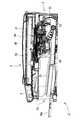
図1は、本発明の実施形態に係る複合機1(本発明の画像形成装置に相当)の外観構成を示すものである。また、図2は、複合機1の内部構成を示す縦断面図である。複合機1は、下部にプリンタ部2を、上部にスキャナ部3を一体的に備えた多機能装置(MFD:Multi Function Device)であり、プリンタ機能、スキャナ機能、コピー機能、ファクシミリ機能を有する。複合機1のうちプリンタ部2が、本発明に係る画像形成装置として実現されたものである。したがって、プリンタ機能以外の機能は任意のものであり、例えば、スキャナ部3がなく、スキャナ機能やコピー機能を有しない単機能のプリンタとして本発明に係る画像形成装置が実施されてもよい。また、複合機1のうちプリンタ部2において、本発明に係る搬送装置が実現されている。なお、プリンタ部2は、本搬送装置を実現する一実施態様にすぎず、本発明に係る搬送装置の用途が、プリンタ部2のような画像形成装置に限定されるものではない。したがって、画像読取装置における自動原稿搬送機能に本搬送装置が適用されてもよい。  FIG. 1 shows an external configuration of a multifunction machine 1 (corresponding to an image forming apparatus of the present invention) according to an embodiment of the present invention. FIG. 2 is a longitudinal sectional view showing the internal configuration of themultifunction machine 1. Themulti-function device 1 is a multi-function device (MFD) having aprinter unit 2 at the bottom and ascanner unit 3 at the top, and has a printer function, a scanner function, a copy function, and a facsimile function. Theprinter unit 2 of themultifunction device 1 is realized as an image forming apparatus according to the present invention. Therefore, functions other than the printer function are arbitrary. For example, the image forming apparatus according to the present invention may be implemented as a single-function printer that does not have thescanner unit 3 and has no scanner function or copy function. In addition, theprinter unit 2 of themultifunction machine 1 implements the transport device according to the present invention. Theprinter unit 2 is only one embodiment for realizing the present conveying device, and the application of the conveying device according to the present invention is not limited to an image forming apparatus such as theprinter unit 2. Therefore, the present conveyance device may be applied to the automatic document conveyance function in the image reading apparatus.

複合機1のプリンタ部2は、主にコンピュータ等の外部情報機器と接続されて、該コンピュータ等から送信された画像データや文書データを含む印刷データに基づいて、記録用紙に画像や文書を記録する。なお、複合機1は、デジタルカメラ等が接続されて、デジタルカメラ等から出力される画像データを記録用紙に記録したり、メモリカード等の各種記憶媒体を装填して、該記憶媒体に記録された画像データ等を記録用紙に記録することも可能である。  Theprinter unit 2 of themultifunction device 1 is mainly connected to an external information device such as a computer, and records images and documents on recording paper based on print data including image data and document data transmitted from the computer. To do. Themulti-function device 1 is connected to a digital camera or the like, and records image data output from the digital camera or the like on a recording sheet or is loaded with various storage media such as a memory card and recorded on the storage medium. It is also possible to record recorded image data or the like on a recording sheet.

図1に示すように、複合機1は高さより横幅及び奥行きが大きい幅広薄型の概ね直方体の外形であり、複合機1の下部がプリンタ部2である。プリンタ部2は、正面に開口2aが形成されている。給紙トレイ20(本発明の給紙部に相当)及び排紙トレイ21(本発明の排紙部に相当)は、開口2aの内部に上下2段に設けられている。給紙トレイ20には、シート状の被搬送体である記録用紙が貯蔵され、例えば、A4サイズ以下のB5サイズ、はがきサイズ等の各種サイズの記録用紙が収容される。給紙トレイ20は、図2に示すように、必要に応じてスライドトレイ20aが引き出されることによりトレイ面が拡大され、例えば、リーガルサイズの記録用紙が収容できるようになる。給紙トレイ20に収容された記録用紙がプリンタ部2の内部へ給送されて所望の画像が記録され、排紙トレイ21へ排出されて保持される。なお、本実施形態では、シート状の被搬送体として記録用紙を例示しているが、被搬送体は記録用紙に限定されるものではなく、合成樹脂シートやその他の湾曲された搬送路を搬送可能なシート状のものが広く含まれる。  As shown in FIG. 1, themultifunction device 1 has a wide, thin, rectangular parallelepiped outer shape whose width and depth are larger than the height, and a lower portion of themultifunction device 1 is aprinter unit 2. Theprinter unit 2 has anopening 2a formed in the front. The paper feed tray 20 (corresponding to the paper feed unit of the present invention) and the paper discharge tray 21 (corresponding to the paper discharge unit of the present invention) are provided in two upper and lower stages inside theopening 2a. Thepaper feed tray 20 stores recording paper that is a sheet-like transported body, and stores recording paper of various sizes such as B5 size and postcard size, for example, A4 size or less. As shown in FIG. 2, the tray surface of thepaper feed tray 20 is expanded by pulling out theslide tray 20 a as necessary, and, for example, a legal size recording sheet can be accommodated. The recording paper stored in thepaper feed tray 20 is fed into theprinter unit 2 to record a desired image, and is discharged to thepaper discharge tray 21 and held. In this embodiment, the recording paper is exemplified as the sheet-like transported body, but the transported body is not limited to the recording paper, and is transported through a synthetic resin sheet or other curved transport path. Possible sheet-like materials are widely included.

複合機1の上部はスキャナ部3であり、所謂フラットベッドスキャナとして構成されている。図1及び図2に示すように、複合機1の天板として開閉自在に設けられた原稿カバー30の下側に、プラテンガラス31及びイメージセンサ32が設けられている。プラテンガラス31には、画像読取りを行う原稿が載置される。プラテンガラス31の下方には、複合機1の奥行き方向(図2の左右方向)を主走査方向とするイメージセンサ32が、複合機1の幅方向(図2の紙面垂直方向)に往復動可能に設けられている。  The upper part of themultifunction device 1 is ascanner unit 3, which is configured as a so-called flat bed scanner. As shown in FIGS. 1 and 2, aplaten glass 31 and animage sensor 32 are provided below adocument cover 30 that can be opened and closed as a top plate of themultifunction machine 1. On theplaten glass 31, an original for reading an image is placed. Below theplaten glass 31, animage sensor 32 whose main scanning direction is the depth direction of the multifunction device 1 (left and right direction in FIG. 2) can reciprocate in the width direction of the multifunction device 1 (perpendicular to the paper surface in FIG. 2). Is provided.

複合機1の正面上部には、プリンタ部2やスキャナ部3を操作するための操作パネル4が設けられている。操作パネル4は、各種操作ボタンや液晶表示部から構成されている。複合機1は、操作パネル4からの操作指示に基づいて動作する。複合機1が外部のコンピュータに接続されている場合には、該コンピュータからプリンタドライバ又はスキャナドライバを介して送信される指示に基づいても複合機1が動作する。複合機1の正面の左上部には、スロット部5が設けられている。スロット部5には、記憶媒体である各種小型メモリカードが装填可能である。操作パネル4において所定の操作を行うことにより、スロット部5に装填された小型メモリカードに記憶された画像データが読み出される。読み出された画像データに関する情報は、操作パネル4の液晶表示部に表示され、この表示に基づいて、任意の画像をプリンタ部2により記録用紙に記録させることができる。  An operation panel 4 for operating theprinter unit 2 and thescanner unit 3 is provided in the upper front portion of themultifunction machine 1. The operation panel 4 includes various operation buttons and a liquid crystal display unit. Themultifunction device 1 operates based on an operation instruction from the operation panel 4. When themultifunction device 1 is connected to an external computer, themultifunction device 1 also operates based on an instruction transmitted from the computer via a printer driver or a scanner driver. A slot portion 5 is provided in the upper left part of the front surface of themultifunction machine 1. The slot unit 5 can be loaded with various small memory cards as storage media. By performing a predetermined operation on the operation panel 4, the image data stored in the small memory card loaded in the slot unit 5 is read out. Information about the read image data is displayed on the liquid crystal display unit of the operation panel 4, and an arbitrary image can be recorded on the recording paper by theprinter unit 2 based on this display.

以下、図2から図8を参照して複合機1の内部構成、特にプリンタ部2の構成について説明する。図2に示すように、複合機1の底側に給紙トレイ20が設けられ、給紙トレイ20の奥側に分離傾斜板22が設けられている。分離傾斜板22は、給紙トレイ20から重送された記録用紙を分離して、最上位置の記録用紙を上方へ案内する。用紙搬送路23は、分離傾斜板22から上方へ向かった後、正面側へ曲がって、複合機1の背面側から正面側へと延び、画像記録ユニット24(本発明の画像形成部に相当)を経て排紙トレイ21へ通じている。したがって、給紙トレイ20に収容された記録用紙は、用紙搬送路23により下方から上方へUターンするように案内されて画像記録ユニット24に至り、画像記録ユニット24により画像記録が行われた後、排紙トレイ21に排出される。  Hereinafter, the internal configuration of themulti-function device 1, particularly the configuration of theprinter unit 2, will be described with reference to FIGS. 2 to 8. As shown in FIG. 2, apaper feed tray 20 is provided on the bottom side of themultifunction machine 1, and a separation inclinedplate 22 is provided on the back side of thepaper feed tray 20. The separation inclinedplate 22 separates the recording paper that is double-fed from thepaper feed tray 20 and guides the uppermost recording paper upward. Thesheet conveyance path 23 is directed upward from the separation inclinedplate 22 and then bent to the front side and extends from the rear side to the front side of themultifunction machine 1, and the image recording unit 24 (corresponding to the image forming unit of the present invention). To thepaper discharge tray 21. Accordingly, the recording paper stored in thepaper feed tray 20 is guided by thepaper conveyance path 23 so as to make a U-turn from the lower side to the upper side, reaches theimage recording unit 24, and after image recording is performed by theimage recording unit 24. The paper is discharged to thepaper discharge tray 21.

図3は、プリンタ部2の主要構成を示す部分拡大断面図である。図3に示すように、給紙トレイ20の上側には、給紙トレイ20に積載された記録用紙を用紙搬送路23へ供給する給紙ローラ25が設けられている。給紙ローラ25は、給紙アーム26の先端に軸支されている。給紙ローラ25は、複数のギアが噛合されてなる駆動伝達機構27により、搬送モータの駆動が伝達されて回転する。  FIG. 3 is a partially enlarged cross-sectional view showing the main configuration of theprinter unit 2. As shown in FIG. 3, on the upper side of thepaper feed tray 20, apaper feed roller 25 that supplies the recording paper loaded on thepaper feed tray 20 to thepaper transport path 23 is provided. Thepaper feed roller 25 is pivotally supported at the tip of thepaper feed arm 26. Thepaper feed roller 25 is rotated by adrive transmission mechanism 27 in which a plurality of gears are meshed to transmit the drive of the carry motor.

給紙アーム26は、基軸26aを回動軸として配設されており、給紙トレイ20に接離可能に上下動する。給紙アーム26は、図2に示すように、自重により又はバネ等に付勢されて給紙トレイ20に接触するように下側へ回動されており、給紙トレイ20の挿抜の際に上側へ退避可能に構成されている。給紙アーム26が下側へ回動されることにより、その先端に軸支された給紙ローラ25が給紙トレイ20上の記録用紙に圧接する。その状態で、給紙ローラ25が回転されることにより、給紙ローラ25のローラ面と記録用紙との間の摩擦力により、最上位置の記録用紙が分離傾斜板22へ送り出される。記録用紙は、その先端が分離傾斜板22に当接して上方へ案内され、用紙搬送路23へ送り込まれる。給紙ローラ25によって最上位置の記録用紙が送り出される際に、その直下の記録用紙が摩擦や静電気の作用によって共に送り出される場合があるが、該記録用紙は分離傾斜板22との当接によって制止される。  Thepaper feed arm 26 is arranged with abase shaft 26 a as a rotation shaft, and moves up and down so as to be able to contact and separate from thepaper feed tray 20. As shown in FIG. 2, thepaper feed arm 26 is rotated downward so as to come into contact with thepaper feed tray 20 by its own weight or biased by a spring or the like. It is configured to be retractable upward. When thepaper feed arm 26 is rotated downward, thepaper feed roller 25 pivotally supported at the tip of thepaper feed arm 26 comes into pressure contact with the recording paper on thepaper feed tray 20. In this state, when thepaper feeding roller 25 is rotated, the uppermost recording paper is sent to the separation inclinedplate 22 by the frictional force between the roller surface of thepaper feeding roller 25 and the recording paper. The leading edge of the recording sheet abuts against the separation inclinedplate 22 and is guided upward, and is fed into thesheet conveyance path 23. When the uppermost recording paper is sent out by thepaper supply roller 25, the recording paper immediately below the recording paper may be sent out together due to friction or static electricity. However, the recording paper is restrained by contact with the separation inclinedplate 22. Is done.

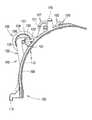
用紙搬送路23は、給紙トレイ20から排紙トレイ21へ記録用紙を下側から上側へ反転させて搬送する所謂Uターンパスであり、装置背面側に円弧状に湾曲された湾曲部17が形成されている。この湾曲部17は、所定間隔で対向する外側ガイド部材18と内側ガイド部材19とから構成されている。外側ガイド部材18には回転コロ16が、用紙搬送路23の幅方向を軸方向として回転自在に設けられている。回転コロ16により、外側ガイド部材18に沿って記録用紙が円滑に搬送される。この外側ガイド部材18及び回転コロ16の詳細な構成については後述される。  Thepaper conveyance path 23 is a so-called U-turn path that conveys recording paper from thepaper feed tray 20 to thepaper discharge tray 21 by reversing the recording paper from the lower side to the upper side, and acurved portion 17 that is curved in an arc shape is formed on the back side of the apparatus. Has been. Thecurved portion 17 includes anouter guide member 18 and aninner guide member 19 that face each other at a predetermined interval. A rotatingroller 16 is provided on theouter guide member 18 so as to be rotatable about the width direction of thepaper transport path 23 as an axial direction. The recording paper is smoothly conveyed along theouter guide member 18 by the rotatingroller 16. Detailed configurations of theouter guide member 18 and therotating roller 16 will be described later.

図3に示すように、用紙搬送路23には、画像記録ユニット24が設けられている。画像記録ユニット24は、インクジェット記録ヘッド39を搭載して主走査方向へ往復動するキャリッジ38を備えている。インクジェット記録ヘッド39には、複合機1内にインクジェット記録ヘッド39とは独立に配置されたインクカートリッジからインクチューブ41(図4参照)を通じてシアン(C)・マゼンタ(M)・イエロー(Y)・ブラック(Bk)の各色インクが供給される。キャリッジ38が往復動される間に、インクジェット記録ヘッド39から各色インクが微小なインク滴として選択的に吐出されることにより、プラテン42上を搬送される記録用紙に画像記録が行われる。なお、図3及び図4には、インクカートリッジは図示されていない。  As shown in FIG. 3, animage recording unit 24 is provided in thepaper transport path 23. Theimage recording unit 24 includes acarriage 38 that is mounted with an inkjet recording head 39 and reciprocates in the main scanning direction. The inkjet recording head 39 includes cyan (C), magenta (M), yellow (Y), and ink through an ink tube 41 (see FIG. 4) from an ink cartridge disposed in themultifunction device 1 independently of the inkjet recording head 39. Black (Bk) color inks are supplied. While thecarriage 38 is reciprocated, each color ink is selectively ejected as fine ink droplets from the inkjet recording head 39, whereby image recording is performed on the recording paper conveyed on theplaten 42. 3 and 4 do not show the ink cartridge.

図4は、プリンタ部2の主要構成を示す平面図である。図4に示すように、用紙搬送路23の上側において記録用紙の搬送方向(図4の上側から下側方向)に所定距離を隔てられて、一対のガイドレール43,44が記録用紙の搬送方向と直交する方向(図4の左右方向)へ略水平方向に延設されている。ガイドレール43,44は、プリンタ部2の筐体内に設けられて、プリンタ部2を構成する各部材を支持するフレームの一部を構成している。キャリッジ38は、ガイドレール43,44を跨ぐようにして記録用紙の搬送方向と直交する方向に摺動可能に載置されている。  FIG. 4 is a plan view showing the main configuration of theprinter unit 2. As shown in FIG. 4, a pair ofguide rails 43 and 44 are separated from each other by a predetermined distance in the recording paper conveyance direction (from the upper side to the lower side in FIG. 4) on the upper side of thepaper conveyance path 23. Is extended in a substantially horizontal direction in a direction orthogonal to the horizontal direction (left-right direction in FIG. 4). The guide rails 43 and 44 are provided in the casing of theprinter unit 2 and constitute a part of a frame that supports each member constituting theprinter unit 2. Thecarriage 38 is placed so as to be slidable in a direction orthogonal to the recording sheet conveyance direction so as to straddle the guide rails 43 and 44.

記録用紙の搬送方向上流側に配設されたガイドレール43は、用紙搬送路23の幅方向(図4の左右方向)の長さがキャリッジ38の往復動範囲より長い平板状のものである。ガイドレール43の上面には、搬送方向下流側の縁部に沿って摺動テープ40が貼られている。摺動テープ40は、キャリッジ38との摺動摩擦を低減するものであり、キャリッジ38の搬送方向上流側の端部が摺動テープ40上に載置されて、摺動テープ40の長手方向に摺動される。  Theguide rail 43 disposed on the upstream side of the recording paper conveyance direction is a flat plate having a length in the width direction (left-right direction in FIG. 4) of thepaper conveyance path 23 longer than the reciprocating range of thecarriage 38. A slidingtape 40 is attached to the upper surface of theguide rail 43 along the edge on the downstream side in the transport direction. The slidingtape 40 reduces sliding friction with thecarriage 38, and an end portion on the upstream side in the transport direction of thecarriage 38 is placed on the slidingtape 40 and slid in the longitudinal direction of the slidingtape 40. Moved.

記録用紙の搬送方向下流側に配設されたガイドレール44は、用紙搬送路23の幅方向の長さがガイドレール43とほぼ同じ長さの平板状のものである。ガイドレール44の上面には、搬送方向下流側の縁部に沿って摺動テープ40が貼られている。キャリッジ38の下流側の端部が摺動テープ40上に載置されて、摺動テープ40の長手方向に摺動される。ガイドレール44の搬送方向上流側の縁部45は、上方へ向かって略直角に曲折されている。ガイドレール43,44に担持されたキャリッジ38は、縁部45をローラ対等の狭持部材により摺動可能に狭持している。これにより、キャリッジ38は、記録用紙の搬送方向に対して位置決めされ、且つ、記録用紙の搬送方向と直交する方向に摺動可能になる。つまり、キャリッジ38は、ガイドレール43,44上に摺動自在に支持され、ガイドレール44の縁部45に案内されて、記録用紙の搬送方向と直交する方向に往復動する。なお、図には表れていないが、摺動テープ40や縁部45には、キャリッジ38の摺動を円滑にするためにグリースなどの潤滑剤が塗布されている。  Theguide rail 44 disposed on the downstream side in the recording paper conveyance direction is a flat plate whose length in the width direction of thepaper conveyance path 23 is substantially the same as that of theguide rail 43. A slidingtape 40 is attached to the upper surface of theguide rail 44 along the edge on the downstream side in the transport direction. The downstream end of thecarriage 38 is placed on the slidingtape 40 and is slid in the longitudinal direction of the slidingtape 40. Theedge 45 on the upstream side in the transport direction of theguide rail 44 is bent at a substantially right angle upward. Thecarriage 38 carried by the guide rails 43 and 44 has theedge 45 slidably held by a holding member such as a roller pair. As a result, thecarriage 38 is positioned with respect to the recording paper conveyance direction and is slidable in a direction perpendicular to the recording paper conveyance direction. That is, thecarriage 38 is slidably supported on the guide rails 43 and 44, guided by theedge 45 of theguide rail 44, and reciprocated in a direction perpendicular to the recording sheet conveyance direction. Although not shown in the drawing, a lubricant such as grease is applied to the slidingtape 40 and theedge 45 in order to make thecarriage 38 slide smoothly.

ガイドレール44の上面には、ベルト駆動機構46が配設されている。ベルト駆動機構46は、用紙搬送路23の幅方向の両端付近にそれぞれ設けられた駆動プーリ47と従動プーリ48との間に、内側に歯が設けられた無端環状のタイミングベルト49が張架されてなるものである。駆動プーリ47の軸にはキャリッジモータから駆動力が入力され、駆動プーリ47の回転によりタイミングベルト49が周運動する。なお、タイミングベルト49は無端環状のもののほか、有端のベルトの両端部をキャリッジ38に固着するものを用いてもよい。  Abelt drive mechanism 46 is disposed on the upper surface of theguide rail 44. In thebelt driving mechanism 46, an endlessannular timing belt 49 having teeth on the inside is stretched between a drivingpulley 47 and a drivenpulley 48 provided near both ends in the width direction of thepaper conveyance path 23. It will be. A driving force is input from the carriage motor to the shaft of the drivingpulley 47, and thetiming belt 49 moves circumferentially as the drivingpulley 47 rotates. In addition to the endless annular belt, thetiming belt 49 may be one that fixes both ends of the endless belt to thecarriage 38.

キャリッジ38は、その底面側においてタイミングベルト49に固着されている。したがって、タイミングベルト49の周運動に基づいて、キャリッジ38が縁部45を基準としてガイドレール43,44上を往復動する。このようなキャリッジ38にインクジェット記録ヘッド39が搭載されて、インクジェット記録ヘッド39が、用紙搬送路23の幅方向を主走査方向として往復動される。  Thecarriage 38 is fixed to thetiming belt 49 on the bottom surface side. Therefore, based on the circumferential motion of thetiming belt 49, thecarriage 38 reciprocates on the guide rails 43 and 44 with theedge 45 as a reference. An inkjet recording head 39 is mounted on such acarriage 38, and the inkjet recording head 39 is reciprocated with the width direction of thepaper transport path 23 as the main scanning direction.

ガイドレール44には、リニアエンコーダのエンコーダストリップ50が配設されている。エンコーダストリップ50は、透明な樹脂からなる帯状のものである。ガイドレール44の幅方向(キャリッジ38の往復動方向)の両端には、その上面から起立するように一対の支持部33,34が形成されている。エンコーダストリップ50は、その両端部が支持部33,34に係止されて、キャリッジ38の往復動方向に沿って架設されている。なお、図には表れていないが、支持部33,34の一方には、板バネが設けられており、該板バネによりエンコーダストリップ50の端部が係止されている。  Theguide rail 44 is provided with anencoder strip 50 of a linear encoder. Theencoder strip 50 is in the form of a strip made of a transparent resin. A pair ofsupport portions 33 and 34 are formed at both ends of theguide rail 44 in the width direction (reciprocating direction of the carriage 38) so as to stand up from the upper surface thereof. Both ends of theencoder strip 50 are engaged with thesupport portions 33 and 34, and are erected along the reciprocating direction of thecarriage 38. Although not shown in the drawing, a leaf spring is provided on one of thesupport portions 33 and 34, and the end portion of theencoder strip 50 is locked by the leaf spring.

エンコーダストリップ50には、光を透過させる透光部と光を遮断する遮光部とが、所定ピッチで長手方向に交互に配置されたパターンが記されている。キャリッジ38の上面のエンコーダストリップ50に対応する位置には、透過型センサである光学センサ35が設けられている。光学センサ35は、キャリッジ38とともにエンコーダストリップ50の長手方向に沿って往復動し、その往復動の際にエンコーダストリップ50のパターンを検知する。インクジェット記録ヘッド39には、インクの吐出を制御するヘッド制御基板が設けられており、該ヘッド制御基板が、光学センサ35の検知信号に基づくパルス信号を出力し、このパルス信号に基づいてキャリッジ38の位置が判断されて、キャリッジ38の往復動が制御される。なお、図4においては、ヘッド制御基板はキャリッジ38に覆われており、図に表れていない。  Theencoder strip 50 has a pattern in which light-transmitting portions that transmit light and light-shielding portions that block light are alternately arranged at a predetermined pitch in the longitudinal direction. Anoptical sensor 35 that is a transmission type sensor is provided at a position corresponding to theencoder strip 50 on the upper surface of thecarriage 38. Theoptical sensor 35 reciprocates along the longitudinal direction of theencoder strip 50 together with thecarriage 38, and detects the pattern of theencoder strip 50 during the reciprocation. The inkjet recording head 39 is provided with a head control board for controlling the ejection of ink. The head control board outputs a pulse signal based on the detection signal of theoptical sensor 35, and thecarriage 38 based on the pulse signal. And the reciprocation of thecarriage 38 is controlled. In FIG. 4, the head control board is covered with thecarriage 38 and is not shown in the figure.

図3及び図4に示すように、用紙搬送路23の下側には、インクジェット記録ヘッド39と対向してプラテン42が配設されている。プラテン42は、キャリッジ38の往復動範囲のうち、記録用紙が通過する中央部分に渡って配設されている。プラテン42の幅は、搬送可能な記録用紙の最大幅より十分に大きいものであり、記録用紙の両端は常にプラテン42の上を通過する。  As shown in FIGS. 3 and 4, aplaten 42 is disposed below thepaper transport path 23 so as to face the inkjet recording head 39. Theplaten 42 is disposed over the central portion of the reciprocating range of thecarriage 38 through which the recording paper passes. The width of theplaten 42 is sufficiently larger than the maximum width of the recording paper that can be conveyed, and both ends of the recording paper always pass over theplaten 42.

図4に示すように、記録用紙が通過しない範囲、すなわちインクジェット記録ヘッド39による画像記録範囲外には、パージ機構51や廃インクトレイ84等のメンテナンスユニットが配設されている。パージ機構51は、インクジェット記録ヘッド39のノズルから気泡や異物を吸引除去するものである。パージ機構51は、インクジェット記録ヘッド39のノズルを覆うキャップ52と、キャップ52を通じてインクジェット記録ヘッド39に接続されるポンプ機構と、キャップ52をインクジェット記録ヘッド39のノズル53に接離させるための移動機構とからなる。なお、図4においては、ポンプ機構及び移動機構は省略されている。インクジェット記録ヘッド39から気泡等の吸引除去を行う際には、インクジェット記録ヘッド39がキャップ52上に位置するようにキャリッジ38が移動される。その状態でキャップ52が上方へ移動されて、インクジェット記録ヘッド39の下面にノズルを密閉するように密着される。ポンプ機構によりキャップ52内が負圧にされることにより、インクジェット記録ヘッド39のノズルからインクとともに気泡や異物が吸引除去される。  As shown in FIG. 4, maintenance units such as thepurge mechanism 51 and thewaste ink tray 84 are disposed outside the range in which the recording paper does not pass, that is, outside the image recording range by theinkjet recording head 39. Thepurge mechanism 51 sucks and removes bubbles and foreign matters from the nozzles of the inkjet recording head 39. Thepurge mechanism 51 includes acap 52 that covers the nozzles of theinkjet recording head 39, a pump mechanism that is connected to theinkjet recording head 39 through thecap 52, and a moving mechanism that moves thecap 52 to and away from the nozzles 53 of theinkjet recording head 39. It consists of. In FIG. 4, the pump mechanism and the moving mechanism are omitted. When sucking and removing bubbles or the like from theinkjet recording head 39, thecarriage 38 is moved so that theinkjet recording head 39 is positioned on thecap 52. In this state, thecap 52 is moved upward and is in close contact with the lower surface of theinkjet recording head 39 so as to seal the nozzle. By making the inside of thecap 52 have a negative pressure by the pump mechanism, bubbles and foreign matters are sucked and removed from the nozzles of the inkjet recording head 39 together with the ink.

廃インクトレイ84は、フラッシングと呼ばれるインクジェット記録ヘッド39からのインクの空吐出を受けるためのものである。廃インクトレイ84は、プラテン42の上面であって、キャリッジ38の往復動範囲内且つ画像記録範囲外に形成されている。なお、図には示されていないが、廃インクトレイ84内にはフェルトが敷設されており、フラッシングされたインクは、該フェルトに吸収されて保持される。これらメンテナンスユニットにより、インクジェット記録ヘッド39内の気泡や混色インクの除去、乾燥防止等のメンテナンスが行われる。  Thewaste ink tray 84 is for receiving idle ink discharge from theinkjet recording head 39 called flushing. Thewaste ink tray 84 is formed on the upper surface of theplaten 42 and within the reciprocating range of thecarriage 38 and outside the image recording range. Although not shown in the figure, felt is laid in thewaste ink tray 84, and the flushed ink is absorbed and held by the felt. These maintenance units perform maintenance such as removal of air bubbles and mixed color ink in the inkjet recording head 39 and prevention of drying.

図4に示すように、プリンタ部2の正面側であって左側面側(図4の右側)には、カートリッジ装着部6が設けられている。図1には閉じられた状態で示されているが、プリンタ部2の筐体の正面には、開閉自在な扉7が設けられている。扉7が開かれると、カートリッジ装着部6が装置正面側に露出され、インクカートリッジが装抜可能になる。カートリッジ装着部6は、4つの収容室に区画されており、各収容室に、シアン・マゼンタ・イエロー・ブラックの各色インクを保持するインクカートリッジが収容される。カートリッジ装着部6からキャリッジ38へは、各色インクに対応した4本のインクチューブ41が引き回されている。キャリッジ38に搭載されたインクジェット記録ヘッド39には、各インクチューブ41を通じて、カートリッジ装着部6に装着されたインクカートリッジから各色インクが供給される。  As shown in FIG. 4, acartridge mounting portion 6 is provided on the front side and the left side (right side in FIG. 4) of theprinter unit 2. Although shown in a closed state in FIG. 1, an openable /closable door 7 is provided on the front surface of the casing of theprinter unit 2. When thedoor 7 is opened, thecartridge mounting portion 6 is exposed to the front side of the apparatus, and the ink cartridge can be removed. Thecartridge mounting portion 6 is divided into four storage chambers, and ink cartridges that hold inks of cyan, magenta, yellow, and black are stored in the storage chambers. Fourink tubes 41 corresponding to the respective color inks are routed from thecartridge mounting portion 6 to thecarriage 38. The inkjet recording head 39 mounted on thecarriage 38 is supplied with ink of each color from the ink cartridge mounted on thecartridge mounting portion 6 through eachink tube 41.

インクチューブ41は、平面視で略U字形状に曲折するように引き回されて固定クリップ36に固定され、固定クリップ36から規制壁37に沿って延出されている。規制壁37は、インクチューブ41が装置正面側に振れないように規制するものであり、インクチューブ41と当接可能な上下方向の壁面を有する。インクチューブ41が略U字形状に湾曲された部分は、いずれの部材にも固定されておらず、キャリッジ38の往復動に追従して姿勢変化する。なお、図4では、固定クリップ36からカートリッジ装着部6までの間のインクチューブ41は省略されている。  Theink tube 41 is routed so as to be bent in a substantially U shape in plan view, is fixed to the fixedclip 36, and extends from the fixedclip 36 along therestriction wall 37. Theregulation wall 37 regulates theink tube 41 so as not to swing to the front side of the apparatus, and has a wall surface in the vertical direction that can come into contact with theink tube 41. The portion where theink tube 41 is bent in a substantially U shape is not fixed to any member, and changes its posture following the reciprocation of thecarriage 38. In FIG. 4, theink tube 41 between the fixedclip 36 and thecartridge mounting portion 6 is omitted.

図3に示すように、画像記録ユニット24の上流側には、一対の搬送ローラ60及びピンチローラ(本発明の搬送ローラ対に相当)が設けられている。なお、図3においては、ピンチローラは他の部材との関係上図示されていないが、搬送ローラ60の下側に圧接状態で配置されている。搬送ローラ60及びピンチローラは、用紙搬送路23を搬送されている記録用紙を狭持してプラテン42上へ搬送する。画像記録ユニット24の下流側には、一対の排紙ローラ62及び拍車ローラ63が設けられている。排紙ローラ62及び拍車ローラ63は、記録済みの記録用紙を狭持して排紙トレイ21へ搬送する。搬送ローラ60及び排紙ローラ62は、LFモータから駆動力が伝達されて、所定の改行幅で間欠駆動する。搬送ローラ60及び排紙ローラ62の回転は同期されている。搬送ローラ60に設けられたロータリーエンコーダは、搬送ローラ60とともに回転するエンコーダディスク61のパターンを光学センサで検知する。この検知信号に基づいて、搬送ローラ60及び排紙ローラ62の回転が制御される。  As shown in FIG. 3, a pair of conveyingrollers 60 and a pinch roller (corresponding to the conveying roller pair of the present invention) are provided on the upstream side of theimage recording unit 24. In FIG. 3, the pinch roller is not shown because of the relationship with other members, but is arranged in a press-contact state below the conveyingroller 60. Thetransport roller 60 and the pinch roller sandwich the recording paper transported through thepaper transport path 23 and transport it onto theplaten 42. A pair ofpaper discharge rollers 62 and spurrollers 63 are provided on the downstream side of theimage recording unit 24. Thepaper discharge roller 62 and thespur roller 63 sandwich the recorded recording paper and convey it to thepaper discharge tray 21. Thetransport roller 60 and thepaper discharge roller 62 are intermittently driven with a predetermined line feed width when a driving force is transmitted from the LF motor. The rotations of thetransport roller 60 and thepaper discharge roller 62 are synchronized. The rotary encoder provided on theconveyance roller 60 detects the pattern of theencoder disk 61 that rotates together with theconveyance roller 60 with an optical sensor. Based on this detection signal, the rotation of thetransport roller 60 and thepaper discharge roller 62 is controlled.

拍車ローラ63は、排紙ローラ62と接離する方向にスライド移動可能に設けられ、コイルバネにより排紙ローラ62に圧接するように付勢されている。拍車ローラ63は、記録済みの記録用紙と圧接するので、記録用紙に記録された画像を劣化させないようにローラ面が拍車状に凹凸されている。排紙ローラ62と拍車ローラ63との間に記録用紙が進入すると、拍車ローラ63は、記録用紙の厚み分だけ付勢力に反して退避し、該記録用紙を排紙ローラ62に圧接するように狭持する。これにより、搬送ローラ62の回転力が確実に記録用紙へ伝達される。ピンチローラも搬送ローラ60に対して同様に設けられ、記録用紙を搬送ローラ60に圧接するように狭持する。  Thespur roller 63 is provided so as to be slidable in a direction in which thespur roller 63 is brought into contact with and separated from thepaper discharge roller 62, and is urged so as to come into pressure contact with thepaper discharge roller 62 by a coil spring. Since thespur roller 63 is in pressure contact with the recorded recording paper, the roller surface is uneven in a spur shape so as not to deteriorate the image recorded on the recording paper. When the recording paper enters between thepaper discharge roller 62 and thespur roller 63, thespur roller 63 retreats against the biasing force by the thickness of the recording paper, and presses the recording paper against thepaper discharge roller 62. Hold it. Thereby, the rotational force of theconveyance roller 62 is reliably transmitted to the recording paper. The pinch roller is also provided in the same manner with respect to theconveyance roller 60, and sandwiches the recording paper so as to be pressed against theconveyance roller 60.

図4に示すように、装置正面側にはメイン基板82が配設されている。メイン基板82からインクジェット記録ヘッド39のヘッド制御基板へはフラットケーブル85を通じて記録用信号等の伝送が行われる。フラットケーブル85は、電気信号を伝送する複数本の導体をポリエステルフィルム等の合成樹脂フィルムで覆って絶縁した薄帯状のものであり、メイン基板82とヘッド制御基板とを電気的に接続している。フラットケーブル85は、薄帯状の表裏面を水平方向に向けてキャリッジ38から延出されている。フラットケーブル85は、インクチューブ41の内側を、平面視で略U字形状に曲折するように引き回されて固定クリップ86に固定され、固定クリップ86からメイン基板82へ延出されている。フラットケーブル85が略U字形状に湾曲された部分は、いずれの部材にも固定されておらず、インクチューブ41と同様に、キャリッジ38の往復動に追従して姿勢変化する。  As shown in FIG. 4, amain substrate 82 is disposed on the front side of the apparatus. A recording signal or the like is transmitted from themain substrate 82 to the head control substrate of the inkjet recording head 39 through theflat cable 85. Theflat cable 85 is a strip-shaped cable in which a plurality of conductors that transmit electrical signals are covered with a synthetic resin film such as a polyester film and insulated, and electrically connects themain board 82 and the head control board. . Theflat cable 85 is extended from thecarriage 38 with the strip-shaped front and back surfaces oriented in the horizontal direction. Theflat cable 85 is drawn around the inside of theink tube 41 so as to be bent in a substantially U shape in plan view, and is fixed to the fixingclip 86, and extends from the fixingclip 86 to themain substrate 82. The portion where theflat cable 85 is bent in a substantially U shape is not fixed to any member, and changes its posture following the reciprocation of thecarriage 38, as with theink tube 41.

以下に、外側ガイド部材18及び回転コロ16の構成が図5〜図10に基づいて詳述される。図5及び図6は、外側ガイド部材18を示すものである。図7〜図9は、ガイドカバー102を示すものである。図10は、ガイド板104を示すものである。  Below, the structure of the outerside guide member 18 and therotation roller 16 is explained in full detail based on FIGS. 5 and 6 show theouter guide member 18. 7 to 9 show theguide cover 102. FIG. 10 shows theguide plate 104.

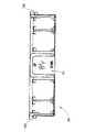
図3に示したように、外側ガイド部材18は、用紙搬送路23の湾曲部17の外側に配置されて、記録用紙を案内するものである。図5及び図6に示すように、外側ガイド部材18は、側面視で第1ガイド面100(本発明のガイド面に相当)が湾曲部17に沿った円弧状をなすように形成されており、ガイド部材本体101に、ガイドカバー102及びガイド板103,104,105,106が組み付けられたものである。  As shown in FIG. 3, theouter guide member 18 is disposed outside thecurved portion 17 of thepaper transport path 23 and guides the recording paper. As shown in FIGS. 5 and 6, theouter guide member 18 is formed such that the first guide surface 100 (corresponding to the guide surface of the present invention) forms an arc shape along thecurved portion 17 in a side view. Aguide cover 102 and guideplates 103, 104, 105, 106 are assembled to the guide membermain body 101.

ガイド部材本体101は、ガイドカバー102及びガイド板103,104,105,106を保持して、装置本体に組み付けられるものであり、摩擦抵抗より成形性や外観を重視した合成樹脂から成形されている。外側ガイド部材18において、記録用紙と接触する第1ガイド面100等はガイドカバー102及びガイド板103〜106により形成されるので、ガイドカバー102及びガイド板103〜106には、記録用紙と第1ガイド面100との摩擦抵抗が小さくなる合成樹脂から成形される。一方、ガイド部材本体101では記録用紙との摩擦を考慮する必要があまりないので、成形性や外観を重視した素材が採用される。光沢紙などの記録用紙との摩擦が少ない合成樹脂として、例えばポリアセタール(POM)があり、成形性や外観のよい樹脂として、例えばABSや耐衝撃性ポリスチレン(HIPS)がある。  The guide membermain body 101 holds theguide cover 102 and theguide plates 103, 104, 105, and 106 and is assembled to the apparatus main body. The guide membermain body 101 is formed from a synthetic resin that places importance on formability and appearance rather than frictional resistance. . In theouter guide member 18, thefirst guide surface 100 that contacts the recording sheet is formed by theguide cover 102 and theguide plates 103 to 106. It is molded from a synthetic resin that reduces the frictional resistance with theguide surface 100. On the other hand, since it is not necessary to consider the friction with the recording paper in the guide membermain body 101, a material that emphasizes formability and appearance is adopted. For example, polyacetal (POM) is a synthetic resin that has little friction with recording paper such as glossy paper, and ABS and impact-resistant polystyrene (HIPS) are examples of resins having good moldability and appearance.

図11は、図5における矢視160からみたガイド部材本体101である。外側ガイド部材18は、装置背面側(図3の右側)から水平方向へ挿抜するようにして、装置本体に着脱される。外側ガイド部材18の着脱は、例えばジャム処理の際に行われるので、ユーザが容易に着脱できるように、不図示のスナップフィット等によりガイド本体101が装置本体に組み付けられている。図11に示すように、ガイド本体101の背面、すなわち装置本体に組み付ける際に装置背面側を向く面のほぼ中央の領域151には、上端側に上を示す「UP」の文字が記され、下端側に下を示す「DOWN」の文字が記されている。  FIG. 11 shows the guide membermain body 101 viewed from thearrow 160 in FIG. Theouter guide member 18 is attached to and detached from the apparatus main body so as to be inserted and removed in the horizontal direction from the apparatus back side (right side in FIG. 3). Since theouter guide member 18 is attached and detached, for example, during jam processing, the guidemain body 101 is assembled to the apparatus main body by a snap fit (not shown) so that the user can easily attach and detach. As shown in FIG. 11, in the rear surface of the guidemain body 101, that is, in theregion 151 at the center of the surface facing the apparatus rear surface when assembled to the apparatus main body, the letters “UP” indicating the upper side are written on the upper end side. On the lower end side, “DOWN” indicating the lower side is marked.

ガイド部材本体101には、上端の両側から水平方向にそれぞれ突出する持ち手152,153が設けられている。外側ガイド部材18が取り付けられる際には、ユーザはガイド部材本体101の持ち手152,153を持って、外側ガイド部材18の長手方向を水平方向として、装置背面側から装置本体に挿入して取り付ける。外側ガイド部材18の湾曲内側には、ガイドカバー102及びガイド板103,104,105,106(図5参照)が取り付けられているので、これらを装置内部側へ向けて外側ガイド部材18を取り付けることは、ユーザに感覚的に理解される。また、複合機1は高さより横幅及び奥行きが大きい幅広薄型の外形なので、外側ガイド部材18の長手方向を水平方向として装置本体に取り付けることも、ユーザに感覚的に理解される。  The guide membermain body 101 is provided withhandles 152 and 153 that protrude horizontally from both sides of the upper end. When theouter guide member 18 is attached, the user holds thehandles 152 and 153 of the guide membermain body 101 and inserts theouter guide member 18 into the apparatus main body from the back side of the apparatus with the longitudinal direction of theouter guide member 18 as the horizontal direction. . Since theguide cover 102 and theguide plates 103, 104, 105, and 106 (see FIG. 5) are attached to the curved inner side of theouter guide member 18, theouter guide member 18 is attached with these facing toward the inside of the apparatus. Is sensuously understood by the user. In addition, since themulti-function device 1 has a wide and thin outline having a width and depth larger than the height, the user can also sensuously understand that the longitudinal direction of theouter guide member 18 is attached to the apparatus main body in the horizontal direction.

一方、外側ガイド部材18の長手方向を水平方向とした場合に、外側ガイド部材18の上下方向は直ちに理解されにくい。例えば、ジャム処理の際に装置本体から取り外された外側ガイド部材18は、ジャム処理の間、机の上や床などに載置される。そして、ジャム処理を終えた後、載置されていた外側ガイド部材18が装置本体に装着される。このように、装置本体から取り外された外側ガイド部材18が別の場所に載置され、ジャム処理などの別の作業が行われると、外側ガイド部材18を取り外した状態の記憶が曖昧になりやすい。  On the other hand, when the longitudinal direction of theouter guide member 18 is the horizontal direction, the vertical direction of theouter guide member 18 is difficult to understand immediately. For example, theouter guide member 18 removed from the apparatus main body during the jam processing is placed on a desk or a floor during the jam processing. After finishing the jam processing, the placedouter guide member 18 is attached to the apparatus main body. As described above, when theouter guide member 18 removed from the apparatus main body is placed in another place and another operation such as jam processing is performed, the memory of the state in which theouter guide member 18 is removed tends to be ambiguous. .

前述したように、ガイド本体101の背面中央の領域151には、「UP」及び「DOWN」の文字が記されているので、ユーザがガイド部材本体101の持ち手152,153を持って、外側ガイド部材18の長手方向を水平方向とした際に、外側ガイド部材18の上下方向が直ちに確認される。したがって、ユーザは、外側ガイド部材18を正しい姿勢で確実に装置本体に装着することができる。なお、外側ガイド部材18の上下方向を示す文字は「UP」及び「DOWN」に限定されるものではなく、複合機1の使用地域を考慮して最適な言語が適宜選択される。また、ガイド部材18の上下方向がユーザに直ちに認識されれば、上下のうちいずれか一方のみが記されていてもよく、さらに、文字に代えて、矢印などの記号により上下方向が記されていてもよい。  As described above, since the characters “UP” and “DOWN” are written in thearea 151 in the center of the back surface of the guidemain body 101, the user holds thehandles 152 and 153 of the guide membermain body 101, and When the longitudinal direction of theguide member 18 is the horizontal direction, the vertical direction of theouter guide member 18 is immediately confirmed. Therefore, the user can reliably attach theouter guide member 18 to the apparatus main body in the correct posture. The characters indicating the vertical direction of theouter guide member 18 are not limited to “UP” and “DOWN”, and an optimal language is appropriately selected in consideration of the area where themultifunction device 1 is used. Further, if the user can immediately recognize the vertical direction of theguide member 18, only one of the upper and lower sides may be marked, and the vertical direction is marked by a symbol such as an arrow instead of characters. May be.

ガイド部材本体101の湾曲内側には、用紙搬送路23の第1ガイド面100の幅方向(図5,6の左右方向)の略中央に、回転コロ16の一部が収容されるコロ収容部107が凹設されている。コロ収容部107には、回転コロ16を保持するガイドカバー102が組み付けられるが、これについては後述される。コロ収容部107の両側には、ガイド板保持部108,109,110,111がそれぞれ凹設されている。ガイド板保持部108〜111には、ガイド板103〜106がそれぞれ組み付けられるがこれについても後述される。  A roller accommodating portion in which a part of therotating roller 16 is accommodated at the approximate center in the width direction (the left-right direction in FIGS. 5 and 6) of thefirst guide surface 100 of thesheet conveyance path 23, on the curved inner side of the guide membermain body 101. 107 is recessed. Aguide cover 102 for holding therotary roller 16 is assembled to theroller accommodating portion 107, which will be described later. Guideplate holding portions 108, 109, 110, and 111 are recessed on both sides of theroller accommodating portion 107.Guide plates 103 to 106 are assembled to the guideplate holding portions 108 to 111, respectively, which will be described later.

ガイド部材本体101の記録用紙搬送方向の下流端には、第2ガイド面112が形成されている。第2ガイド面112は、外側ガイド部材18の記録用紙搬送方向の下流側に設けられた搬送ローラ60及びピンチローラのニップ部に記録用紙を案内するものである。搬送ローラ60及びピンチローラは、画像記録ユニット24により画像記録を行う際にプラテン42上の記録用紙を搬送するものであるから、精密な搬送を実現するためにニップ力が大きく設定されている。また、搬送方向に対して逆転されている或いは停止されている搬送ローラ60及びピンチローラのニップ部に、給紙トレイ20から搬送された記録用紙の先端を当接させるレジスト処理が行われる場合もある。したがって、記録用紙のジャムが生じないように、記録用紙の先端が搬送ローラ60及びピンチローラのニップ部に正確に搬送されることが望まれる。前述したように、ガイド部材本体101は、摩擦抵抗より成形性や外観を重視した素材を選択できるので、第2ガイド面112が高い寸法精度で実現される。  Asecond guide surface 112 is formed at the downstream end of the guide membermain body 101 in the recording sheet conveyance direction. Thesecond guide surface 112 guides the recording sheet to the nip portion of the conveyingroller 60 and the pinch roller provided on the downstream side of theouter guide member 18 in the recording sheet conveying direction. Since theconveyance roller 60 and the pinch roller convey recording paper on theplaten 42 when image recording is performed by theimage recording unit 24, the nip force is set large in order to realize precise conveyance. In some cases, a registration process is performed in which the leading edge of the recording paper conveyed from thepaper feed tray 20 is brought into contact with the nip portion of the conveyingroller 60 and the pinch roller that are reversed or stopped with respect to the conveying direction. is there. Therefore, it is desired that the leading edge of the recording paper is accurately conveyed to the nip portion of the conveyingroller 60 and the pinch roller so that the recording paper does not jam. As described above, since the guide membermain body 101 can select a material that emphasizes formability and appearance rather than frictional resistance, thesecond guide surface 112 is realized with high dimensional accuracy.

図5及び図6に示すように、ガイドカバー102は、回転コロ16を保持してガイド部材本体101のコロ収容部107に組み付けられる。図7に示すように、ガイドカバー102の表面は、記録用紙と接触する第1ガイド面100を形成する。前述したように、ガイドカバー102は、ガイド部材本体101の表面の摩擦抵抗より小さな摩擦抵抗が生じる合成樹脂から成形される。したがって、記録用紙、特に光沢紙のように表面処理がなされている記録用紙に対しても摩擦抵抗が小さく、第1ガイド面100に沿って記録用紙が円滑に案内される。  As shown in FIGS. 5 and 6, theguide cover 102 is assembled to theroller accommodating portion 107 of the guide membermain body 101 while holding the rotatingroller 16. As shown in FIG. 7, the surface of theguide cover 102 forms afirst guide surface 100 that contacts the recording paper. As described above, theguide cover 102 is molded from a synthetic resin that generates a frictional resistance smaller than the frictional resistance of the surface of the guide membermain body 101. Therefore, the frictional resistance is small even with respect to the recording paper, particularly the recording paper that has been surface-treated like glossy paper, and the recording paper is smoothly guided along thefirst guide surface 100.

ガイドカバー102には、記録用紙搬送方向に沿って第1ガイド面100から突出するガイドリブ113が複数形成されている。ガイドリブ113は、第1ガイド面100の幅方向の中央に対して左右対称に配置されている。第1ガイド面100にガイドリブ113が形成されることにより、記録用紙と第1ガイド面100との接触面積が少なくなり、搬送の際の摩擦が低減される。  Theguide cover 102 is formed with a plurality ofguide ribs 113 protruding from thefirst guide surface 100 along the recording paper conveyance direction. Theguide rib 113 is disposed symmetrically with respect to the center of thefirst guide surface 100 in the width direction. By forming theguide rib 113 on thefirst guide surface 100, the contact area between the recording sheet and thefirst guide surface 100 is reduced, and the friction during conveyance is reduced.

図7及び図8に示すように、ガイドカバー102の幅方向両端には、係止凸部114,115が形成されている。係止凸部114は、ガイドカバー102の記録用紙搬送方向の下流端付近から裏面側に突出するように形成された一対のL字形状の部材である。係止凸部114の先端は、記録用紙搬送方向に沿うように曲折されている。係止凸部115は、ガイドカバー102の記録用紙搬送方向の中央付近から裏面側に突出するように形成された一対のL字形状の部材である。係止凸部115の先端は、第1ガイド面100の幅方向外側に曲折されている。  As shown in FIGS. 7 and 8, lockingconvex portions 114 and 115 are formed at both ends in the width direction of theguide cover 102. The lockingprojections 114 are a pair of L-shaped members formed so as to protrude from the vicinity of the downstream end of theguide cover 102 in the recording sheet conveyance direction to the back surface side. The front end of the lockingprojection 114 is bent along the recording paper conveyance direction. The lockingprojections 115 are a pair of L-shaped members formed so as to protrude from the vicinity of the center of theguide cover 102 in the recording sheet conveyance direction to the back surface side. The tip of the lockingprojection 115 is bent outward in the width direction of thefirst guide surface 100.

図6に示すように、ガイド部材本体101のコロ収容部107には、係止凸部114,115に対応して係止凹部116,117が形成されている。本実施形態では、係止凹部116,117は、ガイド部材本体101のコロ収容部107から裏面側に貫通する貫通孔として形成されているが、係止凸部114,115と係合可能な形状であれば、貫通孔に限定されない。  As shown in FIG. 6, lockingrecesses 116 and 117 are formed in theroller accommodating portion 107 of the guide membermain body 101 so as to correspond to the lockingprotrusions 114 and 115. In the present embodiment, the locking recesses 116 and 117 are formed as through holes penetrating from theroller accommodating portion 107 of the guide membermain body 101 to the back surface side, but can be engaged with the lockingprotrusions 114 and 115. If it is, it will not be limited to a through-hole.

ガイドカバー102の係止凸部114,115とコロ収容部107の係止凹部116,117とが係合されることにより、コロ収容部107にガイドカバー102が取り付けられる。コロ収容部107には、ガイドカバー102の裏面に当接する当て面118が形成されている。当て面118は、コロ収容部107の第1ガイド面100の幅方向両側に形成されており、当て面118がガイドカバー102の裏面に当接することにより、ガイドカバー102の位置が第1ガイド面100の湾曲径方向外側に対して拘束される。当て面118にガイドカバー102の裏面が当接された状態で係止凸部114,115と係止凹部116,117とが係合されることにより、係止凹部116,117に対して係止凸部114,115が湾曲内側に押し出されるように緊合される。これにより、ガイドカバー102が湾曲径方向に対して正確に位置決めされるとともに、ガイドカバー102の歪み等が矯正される。なお、当て面118の配置や数は特に限定されないが、本実施形態にように、ガイドカバー102において歪みや寸法誤差が生じやすい縁部に配置されることが好適であり、また、当て面118を、ガイドカバー102の裏面に対して記録用紙の搬送方向に隔てて複数設けることとしてもよい。  Theguide cover 102 is attached to theroller housing portion 107 by engaging the lockingconvex portions 114 and 115 of theguide cover 102 with the lockingrecess portions 116 and 117 of theroller housing portion 107. Acontact surface 118 that abuts against the back surface of theguide cover 102 is formed in theroller housing portion 107. The contact surfaces 118 are formed on both sides in the width direction of thefirst guide surface 100 of theroller accommodating portion 107, and the position of theguide cover 102 is set to the first guide surface by the contact surfaces 118 contacting the back surface of theguide cover 102. 100 is restrained against the outside in the radial direction of the curve. When the back surface of theguide cover 102 is in contact with thecontact surface 118, the lockingprojections 114 and 115 are engaged with the locking recesses 116 and 117, thereby locking the locking recesses 116 and 117. Theprotrusions 114 and 115 are fastened so as to be pushed out inside the curve. As a result, theguide cover 102 is accurately positioned with respect to the curved radial direction, and distortion or the like of theguide cover 102 is corrected. The arrangement and number of the contact surfaces 118 are not particularly limited. However, as in the present embodiment, it is preferable that the contact surfaces 118 be disposed on the edge portion where the distortion and dimensional error are likely to occur in theguide cover 102. A plurality of the guide covers 102 may be provided apart from the back surface of theguide cover 102 in the recording sheet conveyance direction.

コロ収容部107の第1ガイド面100の幅方向の一方には、ガイドカバー102の側面に当接する当て面119が形成されている。当て面119がガイドカバー102の側面に当接することにより、ガイドカバー102の位置が第1ガイド面100の幅方向に対して拘束される。これにより、コロ収容部107に対するガイドカバー102のガタツキが抑えられるとともに、ガイドカバー102が第1ガイド面100の幅方向に対して正確に位置決めされる。これにより、ガイドカバー102の第1ガイド面100が、ガイド板103〜106により形成される第1ガイド面100と略同一面をなす。なお、本実施形態では、コロ収容部107の第1ガイド面100の幅方向の一方に当て面119を設けたが、当て面119を、その対向位置となる幅方向の他方に設けたり、記録用紙の搬送方向に隔てて複数設けたりする構成としてもよい。  Acontact surface 119 that contacts the side surface of theguide cover 102 is formed on one side in the width direction of thefirst guide surface 100 of theroller accommodating portion 107. When thecontact surface 119 contacts the side surface of theguide cover 102, the position of theguide cover 102 is restrained with respect to the width direction of thefirst guide surface 100. As a result, rattling of theguide cover 102 with respect to theroller accommodating portion 107 is suppressed, and theguide cover 102 is accurately positioned with respect to the width direction of thefirst guide surface 100. Accordingly, thefirst guide surface 100 of theguide cover 102 is substantially flush with thefirst guide surface 100 formed by theguide plates 103 to 106. In this embodiment, thecontact surface 119 is provided on one side in the width direction of thefirst guide surface 100 of theroller accommodating portion 107. However, thecontact surface 119 is provided on the other side in the width direction that is the opposite position, or recording is performed. A configuration may be adopted in which a plurality of papers are provided apart in the paper transport direction.

図8に示すように、ガイドカバー102の裏面側には、回転コロ16を回転自在に支持する軸支部120,121,122が設けられている。ガイドカバー102には、記録用紙の搬送方向に隔てられた貫通孔123,124,125が、第1ガイド面100の幅方向中央に対して左右対称に形成されている。貫通孔123〜125は、ガイドカバー102の表裏面方向に形成されており、貫通孔123〜125を通じて、回転コロ167の外周面の一部が第1ガイド面100側に露出される。軸支部120〜122は、貫通孔123〜125に対応してそれぞれ形成されている。  As shown in FIG. 8,shaft support portions 120, 121, and 122 that rotatably support the rotatingroller 16 are provided on the back surface side of theguide cover 102. In theguide cover 102, throughholes 123, 124, and 125 separated in the recording sheet conveyance direction are formed symmetrically with respect to the center in the width direction of thefirst guide surface 100. The throughholes 123 to 125 are formed in the front and back direction of theguide cover 102, and a part of the outer peripheral surface of the rotary roller 167 is exposed to thefirst guide surface 100 side through the throughholes 123 to 125. Theshaft support portions 120 to 122 are respectively formed corresponding to the throughholes 123 to 125.

回転コロ16は、詳細には、コロ本体の外径が異なる3種類の回転コロ126,127,128である。これらはコロ本体の外径が異なる他は同様の構成なので、最も大径の回転コロ126を例に説明する。図8及び図9に示すように、回転コロ126は、コロ本体129及び軸130が一体に形成されたものであり、ガイドカバー102と同様に、ガイド部材本体101より小さな摩擦抵抗が生じる合成樹脂から成形されてなる。コロ本体129は、ほぼ円柱形状のものであり、その外周面が記録用紙と接触する。軸130は、コロ本体129の軸線方向にコロ本体129から両側に突出されている。  Specifically, therotary rollers 16 are three types ofrotary rollers 126, 127, and 128 having different outer diameters of the roller body. Since these have the same configuration except that the outer diameter of the roller body is different, therotation roller 126 having the largest diameter will be described as an example. As shown in FIGS. 8 and 9, therotary roller 126 has aroller body 129 and ashaft 130 integrally formed, and, like theguide cover 102, a synthetic resin that generates a smaller frictional resistance than theguide member body 101. It is formed from. Theroller body 129 has a substantially cylindrical shape, and its outer peripheral surface is in contact with the recording paper. Theshaft 130 protrudes on both sides from theroller body 129 in the axial direction of theroller body 129.

軸支部120〜122は、回転コロ126〜128をそれぞれ回転自在に軸支して、貫通孔123〜125から回転コロ126〜128の一部を突出させる。これら軸支部120〜122は、回転コロ126〜128の大きさに応じて大きさが異なる他は同様の構成なので、最も大径の回転コロ126に対応する軸支部120を例に説明する。  Theshaft support parts 120 to 122 pivotally support therotating rollers 126 to 128, respectively, and project part of therotating rollers 126 to 128 from the throughholes 123 to 125. Since theseshaft support portions 120 to 122 have the same configuration except that the sizes differ depending on the size of therotary rollers 126 to 128, theshaft support portion 120 corresponding to therotation roller 126 having the largest diameter will be described as an example.

図8及び図9に示すように、軸支部120は、台座131、L字部材132、軸押さえ部材133、及び軸受けリブ134とからなる。台座131は、貫通孔123の両端近傍から裏面側に突出するリブであり、その先端面により回転コロ126の軸130の位置を第1ガイド面の湾曲内側に対して拘束する。台座131の先端面の形状は軸130を支持できるものであれば特に限定されず、平滑面の他、軸130が所定方向に移動しないように段差や溝を形成してもよい。  As shown in FIGS. 8 and 9, theshaft support portion 120 includes apedestal 131, an L-shapedmember 132, ashaft pressing member 133, and bearingribs 134. Thepedestal 131 is a rib that protrudes from the vicinity of both ends of the through-hole 123 toward the back surface side, and restricts the position of theshaft 130 of therotary roller 126 against the curved inner side of the first guide surface by the tip surface thereof. The shape of the tip surface of thepedestal 131 is not particularly limited as long as it can support theshaft 130. In addition to a smooth surface, a step or a groove may be formed so that theshaft 130 does not move in a predetermined direction.

台座131に隣接して、L字部材132及び軸受けリブ134が貫通孔123を介在させて対向位置に設けられている。図9に示すように、L字部材132は、ガイドカバー102の裏面側から湾曲外側へ向かって突出する基部135と、基部135の先端が略直角に曲折された鈎部136とを有する。この基部135と鈎部136の内側に、軸130が当接されて位置決めされる。  Adjacent to thepedestal 131, an L-shapedmember 132 and abearing rib 134 are provided at opposing positions with the throughhole 123 interposed. As shown in FIG. 9, the L-shapedmember 132 has abase portion 135 that protrudes from the back surface side of theguide cover 102 toward the curved outer side, and aflange portion 136 in which the tip of thebase portion 135 is bent at a substantially right angle. Theshaft 130 is abutted and positioned inside thebase portion 135 and theflange portion 136.

鈎部136の内側となる軸受け面137は、回転コロ126が受ける負荷Fに対して略直交する。図9に示すように、外側ガイド部材18に案内される記録用紙の先端は、第1ガイド面100及びガイドリブ113に摺接して、図9の下側から上側へ搬送される。そして、記録用紙の先端が回転コロ126に当接すると、回転コロ126は負荷Fを受ける。この負荷Fは、記録用紙の先端の進行方向とほぼ一致する。鈎部136の軸受け面137は、この負荷Fの方向と直交し、軸受け面137が負荷Fを受ける。  The bearingsurface 137 that is the inner side of theflange 136 is substantially orthogonal to the load F that therotating roller 126 receives. As shown in FIG. 9, the leading edge of the recording sheet guided by theouter guide member 18 is slidably brought into contact with thefirst guide surface 100 and theguide rib 113 and is conveyed from the lower side to the upper side in FIG. When the leading edge of the recording sheet comes into contact with therotating roller 126, therotating roller 126 receives a load F. This load F substantially coincides with the traveling direction of the leading edge of the recording paper. The bearingsurface 137 of theflange 136 is orthogonal to the direction of the load F, and thebearing surface 137 receives the load F.

軸受け面137と台座131の先端面との間には、回転コロ126の軸130を回転自在に支持可能な隙間が形成されている。この隙間に軸130が維持されることにより、軸130の位置が第1ガイド面100の湾曲径方向に対して拘束される。このようにして、台座131とL字部材132との間で回転コロ126の軸130が回転自在に狭持される。  A gap is formed between thebearing surface 137 and the tip surface of thepedestal 131 so that theshaft 130 of therotary roller 126 can be rotatably supported. By maintaining theshaft 130 in this gap, the position of theshaft 130 is constrained with respect to the curved radial direction of thefirst guide surface 100. In this way, theshaft 130 of therotary roller 126 is rotatably held between the base 131 and the L-shapedmember 132.

図8に示すように、軸受けリブ134は、L字部材132の対向位置において、ガイドカバー102の裏面側から湾曲外側へ向かって突出されたものであり、その厚み方向に軸受け孔138が穿設されている。この軸受け孔138に軸130が挿通され、台座131の先端面と相まって、回転コロ126の軸130が所定位置に回転自在に支持される。なお、本実施形態では、軸支部120において、L字部材132がガイドカバー102の端側に、軸受けリブ134が中央側に設けられているが、両部材の相対的な位置は特に限定されない。また、軸受けリブ134に代えて、L字部材132を台座131に隣接して一対設けることとしてもよい。  As shown in FIG. 8, thebearing rib 134 protrudes from the back surface side of theguide cover 102 toward the curved outer side at a position facing the L-shapedmember 132, and abearing hole 138 is formed in the thickness direction thereof. Has been. Theshaft 130 is inserted into thebearing hole 138, and theshaft 130 of therotating roller 126 is rotatably supported at a predetermined position together with the front end surface of thebase 131. In the present embodiment, in theshaft support 120, the L-shapedmember 132 is provided on the end side of theguide cover 102 and thebearing rib 134 is provided on the center side. However, the relative positions of the two members are not particularly limited. Further, a pair of L-shapedmembers 132 may be provided adjacent to the base 131 instead of thebearing ribs 134.

軸押さえ部材133は、ガイドカバー102の裏面からL字部材132の鈎部136へ近接するように延設された弾性変形可能な棒状の部材である。軸押さえ部材133の先端は、台座131とL字部材132との間に狭持された軸130に当接する位置まで延出されている。軸押さえ部材133の先端が軸130に当接されることにより、台座131とL字部材132との間から離脱しないように軸130の位置が拘束される。また、回転コロ126の軸130が台座131とL字部材132との間に挿入される際には、軸押さえ部材133は、ガイドカバー102の裏面側へ撓むように弾性変形し、台座131とL字部材132の鈎部136との間の隙間を開放する。そして、該隙間に軸130が挿入された後は、元の姿勢に弾性復帰する。前述したように、L字部材132の軸受け面137は、記録用紙の当接により回転コロ126が受ける負荷Fの方向に対して略直交する。したがって、負荷Fにより軸押さえ部材133が弾性変形することがなく、記録用紙が搬送される際に、回転コロ126の軸130が台座131とL字部材132の鈎部136との間から離脱することがない。  Theshaft pressing member 133 is an elastically deformable rod-like member that extends from the back surface of theguide cover 102 so as to approach theflange 136 of the L-shapedmember 132. The distal end of theshaft pressing member 133 extends to a position where it comes into contact with theshaft 130 sandwiched between the base 131 and the L-shapedmember 132. When the tip of theshaft pressing member 133 is brought into contact with theshaft 130, the position of theshaft 130 is restrained so as not to be separated from between thepedestal 131 and the L-shapedmember 132. When theshaft 130 of therotating roller 126 is inserted between the base 131 and the L-shapedmember 132, theshaft pressing member 133 is elastically deformed so as to bend toward the back side of theguide cover 102, and thebase 131 and the L A gap between thecharacter member 132 and theflange 136 is opened. Then, after theshaft 130 is inserted into the gap, it returns elastically to its original posture. As described above, the bearingsurface 137 of the L-shapedmember 132 is substantially orthogonal to the direction of the load F received by therotating roller 126 by the contact of the recording paper. Accordingly, theshaft pressing member 133 is not elastically deformed by the load F, and theshaft 130 of therotary roller 126 is detached from between the base 131 and theflange 136 of the L-shapedmember 132 when the recording paper is conveyed. There is nothing.

このようにして、軸支部120が、回転コロ126の軸130を挿入可能に軸支する。軸支部120はガイドカバー102と一体に成形されており、前述したように、ガイドカバー102及び回転コロ126は、ガイド部材本体101より小さな摩擦抵抗が生じる合成樹脂からなるので、軸支部120に軸支された回転コロ126は円滑に回転される。これにより、回転コロ126による摩擦低減が効果的に発揮される。  In this way, theshaft support portion 120 supports theshaft 130 of therotary roller 126 so that theshaft 130 can be inserted. Theshaft support 120 is formed integrally with theguide cover 102. As described above, theguide cover 102 and therotating roller 126 are made of synthetic resin that generates a smaller frictional resistance than the guide membermain body 101. The supportedrotating roller 126 is smoothly rotated. Thereby, the friction reduction by therotating roller 126 is exhibited effectively.

軸支部120に軸支された回転コロ126は、台座131により、その軸130の位置が第1ガイド面100の湾曲内側に対して拘束されている。回転コロ126のコロ本体129は、ガイドリブ113より第1ガイド面100からの突出高さが大きくなるように位置決めされている。これにより、ガイドリブ113に沿って搬送される記録用紙は、回転コロ126のコロ本体129に必ず接触する。記録用紙の負荷Fを受けたコロ本体129は、軸130を中心に回転する。この際に、記録用紙はガイドリブ113に接触せずにコロ本体129の回転に伴って下流側へ搬送される。  Therotary roller 126 pivotally supported by thepivotal support 120 is constrained by the base 131 with respect to the curved inner side of thefirst guide surface 100 by the position of theshaft 130. Theroller body 129 of therotating roller 126 is positioned so that the protruding height from thefirst guide surface 100 is larger than theguide rib 113. Thus, the recording paper conveyed along theguide rib 113 always comes into contact with theroller body 129 of therotary roller 126. Theroller body 129 that receives the load F of the recording paper rotates about theshaft 130. At this time, the recording paper is conveyed to the downstream side as theroller body 129 rotates without contacting theguide rib 113.

また、回転コロ126は、コロ本体129と軸130とが一体に形成されているので、部材間の公差の影響が減少される。仮に、コロ本体129と軸130とを別の部材により形成すれば、軸130に対してコロ本体129が回転するように所定の公差を設ける必要がある。また、仮に、軸130をガイドカバー102とコロ収容部107とで狭持するように軸支するとすれば、ガイドカバー102とコロ収容部107とのガタ(公差)が回転コロ126の位置に影響する。したがって、コロ本体129と軸130とを一体に形成し、該軸130がガイドカバー102に一体に成型された軸支部120で位置決めされることにより、部材間の公差(ガタ)の累積による回転コロ126の位置ズレが低減され、回転コロ126の位置、特にガイドリブ113に対するコロ本体129の位置が高精度に維持される。  In addition, since theroller body 129 and theshaft 130 are integrally formed in therotary roller 126, the influence of the tolerance between members is reduced. If theroller body 129 and theshaft 130 are formed of different members, it is necessary to provide a predetermined tolerance so that theroller body 129 rotates with respect to theshaft 130. Further, if theshaft 130 is pivotally supported so as to be held between theguide cover 102 and theroller accommodating portion 107, the backlash (tolerance) between theguide cover 102 and theroller accommodating portion 107 affects the position of therotating roller 126. To do. Therefore, the rollermain body 129 and theshaft 130 are integrally formed, and theshaft 130 is positioned by theshaft support portion 120 formed integrally with theguide cover 102, whereby the rotating roller due to the accumulation of tolerances (backlash) between the members. 126 is reduced, and the position of therotary roller 126, particularly the position of theroller body 129 with respect to theguide rib 113, is maintained with high accuracy.

他の軸支部121,122については詳述されないが、軸支部120と同様の構成で回転コロ127,128をそれぞれ回転自在に軸支する。軸支部121,122に軸支された回転コロ127,128も、同様に、そのコロ本体が、ガイドリブ113より第1ガイド面100からの突出高さが大きくなるように位置決めされている。これにより、ガイドリブ113に沿って搬送される記録用紙は、回転コロ126〜128の各コロ本体に必ず接触し、各コロ本体の回転に伴って下流側へ搬送される。  Although the othershaft support portions 121 and 122 are not described in detail, therotary rollers 127 and 128 are rotatably supported by the same configuration as theshaft support portion 120. Similarly, therotary rollers 127 and 128 that are pivotally supported by thepivotal support portions 121 and 122 are also positioned so that the roller main body has a protruding height from thefirst guide surface 100 larger than that of theguide rib 113. As a result, the recording paper conveyed along theguide rib 113 always comes into contact with the roller bodies of therotating rollers 126 to 128 and is conveyed downstream as the roller bodies rotate.

このように、回転コロ126〜128が、記録用紙の搬送方向に隔てられてガイドカバー102に設けられることにより、第1ガイド面100に沿って湾曲されながら搬送される記録用紙が、各回転コロ126〜128により連続的に案内され、第1ガイド面100による記録用紙の案内が円滑なものになる。  As described above, the rotatingrollers 126 to 128 are provided in theguide cover 102 so as to be separated in the recording sheet conveying direction, so that the recording sheet conveyed while being curved along thefirst guide surface 100 can be rotated. The continuous guidance is performed by 126 to 128, and the guidance of the recording paper by thefirst guide surface 100 becomes smooth.

また、回転コロ126〜128の各コロ本体の径は、記録用紙搬送方向の上流側の回転コロのコロ本体ほど大径になる。つまり、回転コロ126,127,128の順にそのコロ本体の径が大きい。各コロ本体がガイドリブ113から突出する高さが同等であれば、コロ本体の径が大きいほど、ガイドリブ113の表面とコロ本体の外周面とのなす角度が180°に近い鈍角になる。つまり、本実施形態では、最も下流側に配置された回転コロ126のコロ本体129の外周面とガイドリブ113の表面とのなす角度が最も180°に近い鈍角である。この角度が180°に近づくほど、ガイドリブ113に沿って案内される記録用紙の先端がコロ本体の外周面に当接する際の負荷が小さくがなり、逆に90°に近づくほど大きくなる。つまり、この角度が180°に近い鈍角をなすほど、記録用紙の先端とコロ本体の外周面とが接触する際の角度を小さくすることができ、記録用紙が回転コロに接触する際の衝撃が軽減される。  Further, the diameter of each roller body of therotating rollers 126 to 128 becomes larger as the roller body of the rotating roller on the upstream side in the recording paper conveyance direction. That is, the diameter of the roller body is larger in the order of therotating rollers 126, 127, and 128. If the height at which each roller body protrudes from theguide rib 113 is the same, the larger the diameter of the roller body, the more the obtuse angle between the surface of theguide rib 113 and the outer peripheral surface of the roller body becomes 180 °. That is, in this embodiment, the angle formed by the outer peripheral surface of theroller body 129 of therotary roller 126 arranged on the most downstream side and the surface of theguide rib 113 is an obtuse angle that is closest to 180 °. As this angle approaches 180 °, the load when the leading edge of the recording paper guided along theguide rib 113 comes into contact with the outer peripheral surface of the roller body decreases, and conversely increases as it approaches 90 °. That is, as the angle becomes an obtuse angle close to 180 °, the angle at which the leading edge of the recording paper contacts the outer peripheral surface of the roller body can be reduced, and the impact when the recording paper contacts the rotating roller is reduced. It is reduced.

ガイドリブ113に沿って搬送される記録用紙は、最も下流側に配置された回転コロ126に接触する際の衝撃が最も小さい。記録用紙が、次に回転コロ127に接触する際には、該記録用紙の先端付近は、回転コロ126に乗り上げてガイドリブ113から若干浮いた状態になるので、搬送方向に並列された回転コロ126〜128の搬送方向下流側へ向かうほど、記録用紙が接触する際の衝撃が小さくなる。したがって、搬送方向下流側の回転コロ127,128は、そのコロ本体の径を順次小さくすることが可能であり、これにより、回転コロ127,128がガイドカバー102の裏面側から突出する高さが低くなり、外側ガイド部材18の小型化が実現される。  The recording sheet conveyed along theguide rib 113 has the smallest impact when it comes into contact with therotating roller 126 arranged on the most downstream side. When the recording sheet next contacts therotating roller 127, the vicinity of the leading end of the recording sheet rides on therotating roller 126 and slightly floats from theguide rib 113. Therefore, therotating roller 126 arranged in parallel in the transport direction. The impact at the time when the recording paper comes into contact decreases as it goes to the downstream side in the conveying direction of .about.128. Accordingly, the diameters of the roller bodies of therotary rollers 127 and 128 on the downstream side in the transport direction can be sequentially reduced, and the height at which therotary rollers 127 and 128 protrude from the back side of theguide cover 102 is thereby increased. As a result, theouter guide member 18 is reduced in size.

このように回転コロ126〜128が組み付けられたガイドカバー102がガイド部材本体101のコロ収容部107に組み付けられる。回転コロ126〜128は、ガイドカバー102に一体に形成された軸支部120〜122にそれぞれ軸支されており、ガイドカバー102をどのような姿勢にしても、ガイドカバー102から回転コロ126〜128が脱離することがない。これにより、ガイド部材本体101への回転コロ126〜128の組み付けが容易である。  Thus, theguide cover 102 to which therotating rollers 126 to 128 are assembled is assembled to theroller accommodating portion 107 of the guide membermain body 101. Therotating rollers 126 to 128 are respectively supported byshaft support portions 120 to 122 formed integrally with theguide cover 102, and therotating rollers 126 to 128 extend from theguide cover 102 to any posture. Does not desorb. Thereby, the assembly | attachment of the rotating rollers 126-128 to the guide membermain body 101 is easy.

ガイドカバー102がガイド部材本体101のコロ収容部107に組み付けられることにより、回転コロ126〜128は、その軸を記録用紙の搬送方向と直交させて第1ガイド面100に配置される。コロ収容部107は、ガイド部材本体101において第ガイド面100の幅方向の略中央に設けられているので、回転コロ126〜128も第1ガイド面100の略中央に配置される。図5及び図6に示すように、ガイド部材本体101の湾曲内側は、幅方向中央が湾曲内側へ盛り上がる形状をなしている。これにより、幅方向中央の第1ガイド面100を形成するガイドカバー102が湾曲内側へ膨出され、A4サイズやB5サイズ、はがきなどの各種サイズの記録用紙に対して回転コロ126〜128が確実に接触される。特に、記録用紙の中央を第1ガイド面100の幅方向の中央に合致させる所謂センターレジで記録用紙が搬送される場合に、記録用紙の中央に回転コロ126〜128が接触され、回転コロ126〜128による摩擦低減が効果的に発揮される。  By assembling theguide cover 102 into theroller accommodating portion 107 of the guide membermain body 101, therotary rollers 126 to 128 are arranged on thefirst guide surface 100 with their axes orthogonal to the recording paper conveyance direction. Since theroller accommodating portion 107 is provided at the approximate center in the width direction of thefirst guide surface 100 in the guide membermain body 101, the rotatingrollers 126 to 128 are also disposed at the approximate center of thefirst guide surface 100. As shown in FIGS. 5 and 6, the curved inner side of the guide membermain body 101 has a shape in which the center in the width direction rises toward the curved inner side. As a result, theguide cover 102 that forms thefirst guide surface 100 in the center in the width direction bulges inwardly, and therotating rollers 126 to 128 are reliably secured to recording paper of various sizes such as A4 size, B5 size, and postcard. Touched. In particular, when the recording paper is conveyed by a so-called center register in which the center of the recording paper coincides with the center of thefirst guide surface 100 in the width direction, the rotatingrollers 126 to 128 are brought into contact with the center of the recording paper, and therotating roller 126. The friction reduction by ~ 128 is effectively exhibited.

記録用紙と接触した回転コロ126〜128は、記録用紙の搬送方向に回転して第1ガイド面100又はガイドリブ113に摺接する記録用紙を低摩擦で搬送する。回転コロ126〜128は、コロ本体と軸とが一体に形成されているので、コロ本体と軸との間のガタによる振動音は発生しない。これにより、回転コロ126〜128の動作音が減少される。  Therotating rollers 126 to 128 that are in contact with the recording sheet rotate in the recording sheet conveyance direction and convey the recording sheet that is in sliding contact with thefirst guide surface 100 or theguide rib 113 with low friction. In therotary rollers 126 to 128, since the roller body and the shaft are integrally formed, vibration sound due to looseness between the roller body and the shaft is not generated. Thereby, the operation sound of therotating rollers 126 to 128 is reduced.

図5及び図6に示すように、ガイド板103〜106は、ガイド部材本体101のガイド板保持部108〜111にそれぞれ組み付けられる。ガイド板103〜106の表面は、記録用紙と接触する第1ガイド面100を形成する。前述したように、ガイド板103〜106は、ガイド部材本体101の表面の摩擦抵抗より小さな摩擦抵抗が生じる合成樹脂から成形される。したがって、記録用紙、特に光沢紙のように表面処理がなされている記録用紙に対しても摩擦抵抗が小さく、第1ガイド面100に沿って記録用紙が円滑に案内される。  As shown in FIGS. 5 and 6, theguide plates 103 to 106 are assembled to the guideplate holding portions 108 to 111 of the guide membermain body 101, respectively. The surfaces of theguide plates 103 to 106 form afirst guide surface 100 that comes into contact with the recording paper. As described above, theguide plates 103 to 106 are molded from a synthetic resin that generates a frictional resistance smaller than the frictional resistance of the surface of the guide membermain body 101. Therefore, the frictional resistance is small even with respect to the recording paper, particularly the recording paper that has been surface-treated like glossy paper, and the recording paper is smoothly guided along thefirst guide surface 100.

ガイド板103〜106は、ガイド部材本体101に取り付けられる幅方向に位置に応じて大きやガイドリブ139の形状が異なる他は同様の構成なので、ガイド板104を例に詳細な構成を説明し、他のガイド板103,105,106の説明は省略する。  Theguide plates 103 to 106 have the same configuration except that the size and the shape of theguide rib 139 differ depending on the position in the width direction attached to the guide membermain body 101. Therefore, the detailed configuration will be described with theguide plate 104 as an example. Description of theguide plates 103, 105, 106 will be omitted.

図10に示すように、ガイド板104には、記録用紙搬送方向に沿って第1ガイド面100から突出するガイドリブ139が複数形成されている。ガイドリブ139は、記録用紙搬送方向に沿った側壁のうち第1ガイド面100の幅方向中央側の側壁140と第1ガイド面100とのなす角度が鈍角になるように形成されている。記録用紙は、外側ガイド部材18の第1ガイド面100に対してセンターレジで搬送されるので、各ガイドリブ139の側壁140は、記録用紙の側縁と接触し得る。例えば、記録用紙の側縁がガイドリブ139の側壁140に接触しながら搬送される場合に、仮に側壁140が第1ガイド面100に対して直角に形成されていれば、記録用紙の斜行などによりジャムが生じたり、記録用紙の側縁にコルゲーションと称される波状の皺が生じたりする。側壁140が鈍角にされることにより、記録用紙の側縁が、側壁140に案内されるようにして、ガイドリブ139に容易に乗り上げることができるので、ジャムやコルゲーションが防止される。また、ガイドリブ139により、記録用紙と第1ガイド面100との接触面積が少なくなり、搬送の際の摩擦が低減される。  As shown in FIG. 10, theguide plate 104 is formed with a plurality ofguide ribs 139 protruding from thefirst guide surface 100 along the recording sheet conveyance direction. Theguide rib 139 is formed such that an angle formed between theside wall 140 on the center side in the width direction of thefirst guide surface 100 and thefirst guide surface 100 among the side walls along the recording sheet conveyance direction is an obtuse angle. Since the recording sheet is conveyed by the center register with respect to thefirst guide surface 100 of theouter guide member 18, theside wall 140 of eachguide rib 139 can be in contact with the side edge of the recording sheet. For example, when the side edge of the recording sheet is conveyed while being in contact with theside wall 140 of theguide rib 139, if theside wall 140 is formed at a right angle to thefirst guide surface 100, the recording sheet may be skewed. A jam occurs, or a wavy wrinkle called corrugation occurs on the side edge of the recording paper. By making theside wall 140 an obtuse angle, the side edge of the recording paper can be easily climbed on theguide rib 139 so that the side edge of the recording paper is guided to theside wall 140, thereby preventing jamming and corrugation. Further, theguide rib 139 reduces the contact area between the recording sheet and thefirst guide surface 100 and reduces the friction during conveyance.

ガイド板104の記録用紙搬送方向の下流端には、搬送方向へ突出するガイド爪141が形成されている。ガイド爪141は、ガイドリブ139に対応した位置に設けられており、ガイド板104がガイド部材本体101に組み付けられることにより、図5に示すように、ガイド部材本体101の第2ガイド面112の直上流側に延出される。ガイド爪141は、第1ガイド面100と略同一面になるように、ガイド板104と一体に形成されている。このガイド爪141に案内されて、記録用紙の先端が所望の角度で第2ガイド面112に至る。つまり、第2ガイド面112に至るまで摩擦抵抗の小さいガイド爪141に記録用紙が案内されることにより、記録用紙の搬送が円滑になる。  Aguide claw 141 protruding in the transport direction is formed at the downstream end of theguide plate 104 in the recording paper transport direction. Theguide claws 141 are provided at positions corresponding to theguide ribs 139. When theguide plate 104 is assembled to the guide membermain body 101, theguide claws 141 are arranged directly on thesecond guide surface 112 of the guide membermain body 101 as shown in FIG. It is extended upstream. Theguide claw 141 is formed integrally with theguide plate 104 so as to be substantially flush with thefirst guide surface 100. Guided by theguide claw 141, the leading edge of the recording sheet reaches thesecond guide surface 112 at a desired angle. That is, the recording sheet is guided to theguide claw 141 having a small frictional resistance up to thesecond guide surface 112, so that the recording sheet is smoothly conveyed.

図10に示すように、隣接するガイド爪141の間は、第1ガイド面100が設けられていない空間150である。また、ガイド本体101に組み付けられた状態において、ガイド爪141は、ガイド部材本体101から若干浮いた状態にある。したがって、ガイド爪141により案内される記録用紙は、ガイド爪141の間では他の部材に接触しない。これにより、記録用紙の先端が第2ガイド面112に案内される際の摩擦抵抗が更に低減され、第2ガイド面112による搬送ローラ60及びピンチローラのニップ部への正確な案内が確実に実現される。  As illustrated in FIG. 10, aspace 150 where thefirst guide surface 100 is not provided is between theadjacent guide claws 141. Further, theguide claw 141 is slightly lifted from the guide membermain body 101 in the state assembled to the guidemain body 101. Therefore, the recording paper guided by theguide claws 141 does not contact other members between theguide claws 141. As a result, the frictional resistance when the leading edge of the recording paper is guided to thesecond guide surface 112 is further reduced, and accurate guidance to the nip portion of the conveyingroller 60 and the pinch roller by thesecond guide surface 112 is reliably realized. Is done.

ガイド板104の幅方向両端には、係止凸部142,143が形成されている。係止凸部142は、ガイド板103の記録用紙搬送方向の下流端付近から裏面側に突出するように形成された一対のL字形状の部材である。係止凸部142の先端は、記録用紙搬送方向に沿うように曲折されている。係止凸部143は、ガイド板103の記録用紙搬送方向の中央付近から裏面側に突出するように形成された一対のL字形状の部材である。係止凸部143の先端は、第1ガイド面100の幅方向外側に曲折されている。  Lockingconvex portions 142 and 143 are formed at both ends in the width direction of theguide plate 104. The lockingprojections 142 are a pair of L-shaped members formed so as to protrude from the vicinity of the downstream end of theguide plate 103 in the recording sheet conveyance direction to the back surface side. The front end of the lockingprojection 142 is bent along the recording paper conveyance direction. The lockingprojections 143 are a pair of L-shaped members formed so as to protrude from the vicinity of the center of theguide plate 103 in the recording sheet conveyance direction to the back surface side. The front end of the lockingprojection 143 is bent outward in the width direction of thefirst guide surface 100.

図6に示すように、ガイド部材本体101のガイド板保持部109には、係止凸部142,143に対応して係止凹部144,145が形成されている。本実施形態では、係止凹部144,145は、ガイド部材本体101のガイド板保持部109から裏面側に貫通する貫通孔として形成されているが、係止凸部142,143と係合可能な形状であれば、貫通孔に限定されない。  As shown in FIG. 6, lockingrecesses 144 and 145 are formed in the guideplate holding portion 109 of the guide membermain body 101 corresponding to the lockingprotrusions 142 and 143. In this embodiment, the locking recesses 144 and 145 are formed as through holes penetrating from the guideplate holding portion 109 of the guide membermain body 101 to the back surface side, but can be engaged with the lockingprotrusions 142 and 143. If it is a shape, it is not limited to a through-hole.

ガイド板104の係止凸部142,143とガイド板保持部109の係止凹部144,145とが係合されることにより、ガイド板保持部109にガイド板104が取り付けられる。ガイド板保持部109には、ガイド板104の裏面に当接する当て面146,147,148が形成されている。当て面146は、ガイド板保持部109の第1ガイド面100の幅方向両側であって記録用紙搬送方向の上流端に一対形成されている。当て面146から搬送方向に隔てられて、一対の当て面147,148がそれぞれ形成されている。当て面146,147,148がガイド板104の裏面にそれぞれ当接されることにより、ガイド板104の位置が第1ガイド面100の湾曲径方向外側に対して拘束される。当て面146,147,148にガイド板104の裏面が当接された状態で係止凸部142,143と係止凹部144,145とが係合されることにより、係止凹部144,145に対して係止凸部142,143が湾曲内側に押し出されるように緊合される。これにより、ガイド板104が湾曲径方向に対して正確に位置決めされるとともに、ガイド板104の歪み等が矯正される。なお、当て面146,147,148の配置や数は特に限定されないが、本実施形態にように、ガイド板104において歪みや寸法誤差が生じやすい縁部に配置されることが好適であり、また、ガイド板104の裏面に対して均等に配置されることが好適である。  Theguide plate 104 is attached to the guideplate holding portion 109 by engaging the lockingconvex portions 142 and 143 of theguide plate 104 with the lockingconcave portions 144 and 145 of the guideplate holding portion 109. The guideplate holding portion 109 is formed withcontact surfaces 146, 147, and 148 that contact the back surface of theguide plate 104. A pair of contact surfaces 146 are formed on both sides in the width direction of thefirst guide surface 100 of the guideplate holding portion 109 and at the upstream end in the recording sheet conveyance direction. A pair of contact surfaces 147 and 148 are formed separately from thecontact surface 146 in the transport direction. The contact surfaces 146, 147, and 148 are brought into contact with the back surface of theguide plate 104, so that the position of theguide plate 104 is restrained with respect to the outside in the curved radial direction of thefirst guide surface 100. The engagingprojections 142, 143 and the engagingrecesses 144, 145 are engaged with the contact surfaces 146, 147, 148 in contact with the back surface of theguide plate 104, whereby the engagingrecesses 144, 145 On the other hand, the lockingprojections 142 and 143 are fastened so as to be pushed out inside the curve. As a result, theguide plate 104 is accurately positioned with respect to the curved radial direction, and the distortion or the like of theguide plate 104 is corrected. The arrangement and number of the contact surfaces 146, 147, and 148 are not particularly limited. However, as in the present embodiment, it is preferable that the contact surfaces 146, 147, and 148 are arranged on the edge portion where the distortion and dimensional error are likely to occur in theguide plate 104. It is preferable that theguide plate 104 is arranged evenly with respect to the back surface.

ガイド板保持部109の第1ガイド面100の幅方向の一方には、ガイド板104の側面に当接される当て面149が形成されている。当て面149がガイド板104の側面に当接されることにより、ガイド板104の位置が第1ガイド面100の幅方向に対して拘束される。これにより、ガイド板保持部109に対するガイド板104のガタツキが抑えられるとともに、ガイド板104が第1ガイド面100の幅方向に対して正確に位置決めされる。これにより、ガイド板103〜106により形成される第1ガイド面100が略同一面になる。このようにして、成形性や外観より摩擦抵抗の小ささを重視した素材からガイド板104を形成することによりガイド板104に生じた歪みが矯正されるとともに、寸法誤差の影響が低減される。なお、本実施形態では、ガイド板保持部109の第1ガイド面100の幅方向の一方に当て面149を設けたが、当て面149を、その対向位置となる幅方向の他方に設けたり、記録用紙の搬送方向に隔てて複数設けたりする構成としてもよい。  On one side in the width direction of thefirst guide surface 100 of the guideplate holding portion 109, acontact surface 149 that is in contact with the side surface of theguide plate 104 is formed. When thecontact surface 149 is in contact with the side surface of theguide plate 104, the position of theguide plate 104 is restrained with respect to the width direction of thefirst guide surface 100. As a result, rattling of theguide plate 104 with respect to the guideplate holding portion 109 is suppressed, and theguide plate 104 is accurately positioned with respect to the width direction of thefirst guide surface 100. Thereby, the1st guide surface 100 formed of the guide plates 103-106 becomes a substantially identical surface. In this manner, theguide plate 104 is formed from a material that emphasizes a small frictional resistance rather than formability and appearance, thereby correcting distortion generated in theguide plate 104 and reducing the influence of dimensional errors. In the present embodiment, thecontact surface 149 is provided on one side in the width direction of thefirst guide surface 100 of the guideplate holding portion 109, but thecontact surface 149 is provided on the other side in the width direction that is the opposite position. A plurality of recording papers may be provided in the conveyance direction of the recording paper.

ガイド板103,105,106及びガイド板保持部108,110,111については詳述されないが、ガイド板104及びガイド板保持部109と同様の構成であり、各ガイド板103,105,106は、係止凸部と係止凹部との係合によりガイド板保持部108,110,111にそれぞれ組み付けられ、ガイド板保持部108,110,111に形成された当て面に裏面及び側面が当接された状態で、係止凸部と係止凹部とが緊合されることにより、ガイド板103,105,106に生じた歪みが矯正されるとともに、寸法誤差の影響が低減される。  Theguide plates 103, 105, 106 and the guideplate holding portions 108, 110, 111 are not described in detail, but have the same configuration as theguide plate 104 and the guideplate holding portion 109. The back surface and the side surface are brought into contact with the contact surfaces formed on the guideplate holding portions 108, 110, and 111 by the engagement of the locking projections and the locking recesses, respectively. In this state, the engagement convex portion and the engagement concave portion are brought into close contact with each other, whereby distortion generated in theguide plates 103, 105, and 106 is corrected and the influence of the dimensional error is reduced.

このようにして、ガイド板103〜106により、略同一面の第1ガイド面100が形成される。外側ガイド部材18の湾曲内側のほぼ全域に形成される第1ガイド面100が、その幅方向に並設された複数のガイド板103〜106に分割されて構成されることにより、1枚のガイド板103〜106に生じる歪みや寸法誤差が低減される。つまり、前述したように、ガイド板103を形成する合成樹脂は、摩擦抵抗を優先させたものなので、成型性や外観で劣ることがあり、歪みや寸法誤差が生じやすい。このような歪みや寸法誤差は、成形品の大きさが大きくなるほど、つまり1枚のガイド板103〜106を大きくするほど大きくなる。仮に、第1ガイド面100を1,2枚のガイド板で構成することとすれば、該ガイド板の歪みや撓みが大きくなり、その矯正が困難になり、均一な第1ガイド面100を形成することが困難になる。したがって、第1ガイド面100が複数のガイド板103〜106に分割されて構成されることにより、1枚のガイド板103〜106の大きさを小さくすることができ、ガイド板103〜106に生じる歪みが矯正しやすく、寸法誤差を是正することが容易になる。  In this way, thefirst guide surface 100 having substantially the same surface is formed by theguide plates 103 to 106. Thefirst guide surface 100 formed in almost the entire area of theouter guide member 18 inside the curve is divided into a plurality ofguide plates 103 to 106 arranged in parallel in the width direction, whereby one guide is provided. Distortions and dimensional errors that occur in theplates 103 to 106 are reduced. That is, as described above, since the synthetic resin forming theguide plate 103 gives priority to frictional resistance, the moldability and appearance may be inferior, and distortion and dimensional errors are likely to occur. Such distortion and dimensional error increase as the size of the molded product increases, that is, as oneguide plate 103 to 106 increases. If thefirst guide surface 100 is composed of one or two guide plates, the guide plate is greatly distorted and bent, making it difficult to correct and forming the uniformfirst guide surface 100. It becomes difficult to do. Therefore, thefirst guide surface 100 is divided into a plurality ofguide plates 103 to 106, whereby the size of oneguide plate 103 to 106 can be reduced, and theguide plate 103 to 106 is generated. It is easy to correct the distortion and correct the dimensional error.

このように、外側ガイド部材18によれば、コロ本体及び軸が一体に形成された回転コロ126〜128が、ガイドカバー102の軸支部120〜122にそれぞれ支持されるので、部材間の公差の影響が減少され、回転コロ126〜128のガイド面100からの突出高さが高精度に維持される。これにより、ガイド面100又はガイドリブ113に沿って搬送される記録用紙が回転コロ126〜128のコロ本体の所望の位置に確実に当接され、回転コロ126〜128により摩擦低減が装置間差なく安定して発揮される。また、回転コロ126〜128のコロ本体と軸とが一体に形成されているので、コロ本体と軸との間のガタによる振動音が発生せず、回転コロ126〜128の動作音が減少される。これにより、記録用紙が搬送される際の騒音を小さくすることができる。また、回転コロ126〜128がガイドカバー102のみによって支持されているので、ガイド部材本体101に、ガイドカバ102及び回転コロ126〜128を組み付ける作業が容易となる。これにより、外側ガイド部材18の組み付け作業時間が短縮され、製造コストが低減される。  As described above, according to theouter guide member 18, therotary rollers 126 to 128 in which the roller main body and the shaft are integrally formed are supported by theshaft support portions 120 to 122 of theguide cover 102, respectively. The influence is reduced, and the protruding height of therotary rollers 126 to 128 from theguide surface 100 is maintained with high accuracy. Thereby, the recording paper conveyed along theguide surface 100 or theguide rib 113 is surely brought into contact with a desired position of the roller body of therotary rollers 126 to 128, and therotary rollers 126 to 128 reduce friction without difference between apparatuses. It is demonstrated stably. In addition, since the roller main body and the shaft of therotary rollers 126 to 128 are integrally formed, vibration noise due to rattling between the roller main body and the shaft is not generated, and the operation sound of therotary rollers 126 to 128 is reduced. The Thereby, it is possible to reduce noise when the recording paper is conveyed. Further, since therotating rollers 126 to 128 are supported only by theguide cover 102, the work of assembling theguide cover 102 and therotating rollers 126 to 128 to the guide membermain body 101 is facilitated. Thereby, the assembly work time of the outerside guide member 18 is shortened, and manufacturing cost is reduced.

なお、本実施形態では、用紙搬送路23をUターンパスとしたが、本発明に係る搬送装置の搬送路の湾曲部は、Uターンパスの湾曲部に限定されない。また、本実施形態では、外側ガイド部材18の第1ガイド面100が、複数のガイド板103〜106により形成されることとしたが、第1ガイド面100がガイド部材本体101により一体に形成されることとしてもよい。  In the present embodiment, thepaper transport path 23 is a U-turn path, but the curved portion of the transport path of the transport apparatus according to the present invention is not limited to the curved portion of the U-turn path. In the present embodiment, thefirst guide surface 100 of theouter guide member 18 is formed by the plurality ofguide plates 103 to 106, but thefirst guide surface 100 is integrally formed by the guide membermain body 101. It is also good to do.

図1は、本発明の実施形態に係る複合機1の外観構成を示す斜視図である。FIG. 1 is a perspective view showing an external configuration of amultifunction machine 1 according to an embodiment of the present invention.図2は、複合機1の内部構成を示す縦断面図である。FIG. 2 is a longitudinal sectional view showing the internal configuration of themultifunction machine 1.図3は、プリンタ部2の主要構成を示す拡大断面図である。FIG. 3 is an enlarged cross-sectional view showing the main configuration of theprinter unit 2.図4は、プリンタ部2の主要構成を示す平面図である。FIG. 4 is a plan view showing the main configuration of theprinter unit 2.図5は、外側ガイド部材18の構成を示す斜視図である。FIG. 5 is a perspective view showing the configuration of theouter guide member 18.図6は、外側ガイド部材18の分解斜視図である。FIG. 6 is an exploded perspective view of theouter guide member 18.図7は、ガイドカバー102の第1ガイド面100側を示す斜視図である。FIG. 7 is a perspective view showing thefirst guide surface 100 side of theguide cover 102.図8は、ガイドカバー102の裏面側を示す斜視図である。FIG. 8 is a perspective view showing the back side of theguide cover 102.図9は、ガイドカバー102の側面図である。FIG. 9 is a side view of theguide cover 102.図10は、ガイド板104の斜視図である。FIG. 10 is a perspective view of theguide plate 104.図11は、ガイド本体101の矢視160からの背面図である。FIG. 11 is a rear view of the guidemain body 101 as viewed from anarrow 160. FIG.

符号の説明Explanation of symbols

1・・・複合機(画像形成装置)
17・・・湾曲部
18・・・外側ガイド部材
19・・・内側ガイド部材
20・・・給紙トレイ(給紙部)
21・・・排紙トレイ(排紙部)
23・・・用紙搬送路(搬送路)
24・・・画像記録ユニット(画像形成部)
100・・・第1ガイド面(ガイド面)
101・・・ガイド部材本体
102・・・ガイドカバー
107・・・コロ収容部
113・・・ガイドリブ
120,121,122・・・軸支部
126,127,128・・・回転コロ
129・・・コロ本体
130・・・軸
131・・・台座
132・・・L字部材
133・・・軸押さえ部材
137・・・軸受け面
1 ... Multifunction machine (image forming device)
17 ...curved portion 18 ...outer guide member 19 ...inner guide member 20 ... paper feed tray (paper feed unit)
21 ... Paper discharge tray (paper output unit)
23 ... Paper transport path (transport path)
24... Image recording unit (image forming unit)
100 ... 1st guide surface (guide surface)
101 ... guide membermain body 102 ... guidecover 107 ...roller accommodating portion 113 ... guideribs 120, 121, 122 ...shaft support portions 126, 127, 128 ...rotary rollers 129 ... rollersMain body 130 ...shaft 131 ...pedestal 132 ... L-shapedmember 133 ...shaft pressing member 137 ... bearing surface

Claims (10)

Translated fromJapanese
円弧状に湾曲された湾曲部を有し、所定幅で対向するガイド部材により形成された搬送路を通じて、シート状の被搬送体が収容される給紙部から搬送後の被搬送体を保持する排紙部へ被搬送体を搬送する搬送装置であって、
上記搬送路の湾曲部の外側に配置された外側ガイド部材は、
コロ収容部が凹設されたガイド部材本体と、
コロ本体及び軸が一体に形成された回転コロと、
上記回転コロのコロ本体の一部をガイド面から突出させて、該回転コロの軸を回転自在に支持する軸支部を有し、該回転コロの軸が被搬送体の搬送方向と直交するようにして、上記外側ガイド部材のコロ収容部に配設されたガイドカバーと、を具備するものである搬送装置。
Holds the transported body after transport from a paper feed section that houses a sheet-shaped transported body through a transport path formed by a guide member that has a predetermined width and has an arcuate curved portion. A transport device that transports a transported body to a paper discharge unit,
The outer guide member disposed outside the curved portion of the conveyance path is
A guide member body in which the roller accommodating portion is recessed,
A rotating roller integrally formed with a roller body and a shaft;
A part of the roller body of the rotating roller protrudes from the guide surface, and has a shaft support portion that rotatably supports the shaft of the rotating roller so that the axis of the rotating roller is orthogonal to the transport direction of the transported body. And a guide cover disposed in the roller housing portion of the outer guide member.
上記ガイドカバーの軸支部は、
上記回転コロのコロ本体の一部がガイド面から所定高さで突出するように、該回転コロの軸の位置を拘束する台座と、
被搬送体の当接により上記回転コロが受ける負荷方向に対して略直交する軸受け面を有し、該軸受け面と上記台座との間で該回転コロの軸を回転自在に狭持するL字部材と、
上記回転コロの軸を上記台座と上記L字部材との間に挿入可能に弾性変形し、挿入された軸を該台座と該L字部材との間に拘束する軸押さえ部材と、を具備するものである請求項1に記載の搬送装置。
The shaft support of the guide cover is
A pedestal that restrains the position of the axis of the rotating roller so that a part of the roller body of the rotating roller protrudes from the guide surface at a predetermined height;
An L-shape having a bearing surface that is substantially perpendicular to the load direction received by the rotating roller due to the contact of the transported body, and rotatably pinching the shaft of the rotating roller between the bearing surface and the pedestal Members,
A shaft pressing member that elastically deforms the shaft of the rotating roller so as to be insertable between the pedestal and the L-shaped member and restrains the inserted shaft between the pedestal and the L-shaped member; The conveying apparatus according to claim 1, which is a thing.
上記ガイドカバーは、そのガイド面が、上記外側ガイド部材のガイド面と略同一面をなすように該外側ガイド部材のコロ収容部に配設されたものである請求項1又は2に記載の搬送装置。  3. The transport according to claim 1, wherein the guide cover is disposed in a roller accommodating portion of the outer guide member so that a guide surface thereof is substantially flush with a guide surface of the outer guide member. apparatus. 上記回転コロは、被搬送体の搬送方向に隔てられて上記ガイドカバーに複数配設されたものである請求項1から3のいずれかに記載の搬送装置。  The conveying device according to any one of claims 1 to 3, wherein a plurality of the rotating rollers are arranged on the guide cover so as to be separated from each other in the conveying direction of the object to be conveyed. 被搬送体の搬送方向上流側の回転コロのコロ本体が、搬送方向下流側の回転コロのコロ本体より大径である請求項4に記載の搬送装置。  The conveying device according to claim 4, wherein a roller body of a rotating roller on the upstream side in the conveying direction of the object to be conveyed has a larger diameter than a roller body of the rotating roller on the downstream side in the conveying direction. 上記外側ガイド部材は、ガイド面の幅方向の略中央に上記コロ収容部が凹設されたものである請求項1から5のいずれかに記載の搬送装置。  The conveying device according to any one of claims 1 to 5, wherein the outer guide member is configured such that the roller accommodating portion is recessed at a substantially center in the width direction of the guide surface. 上記外側ガイド部材は、被搬送体の搬送方向に沿ってそのガイド面から突出するガイドリブを有し、
上記ガイドカバーの軸支部は、上記ガイドリブよりガイド面からの突出高さが大きくなるように上記回転コロの軸を支持するものである請求項1から6のいずれかに記載の搬送装置。
The outer guide member has a guide rib protruding from the guide surface along the transport direction of the transported body,
The conveying device according to any one of claims 1 to 6, wherein the shaft support portion of the guide cover supports the shaft of the rotating roller such that a protruding height from the guide surface is larger than the guide rib.
上記回転コロ及び上記ガイドカバーは、上記外側ガイド部材のガイド面の摩擦抵抗より小さな摩擦抵抗が生じる合成樹脂からなるものである請求項1から7のいずれかに記載の搬送装置。  The conveying device according to any one of claims 1 to 7, wherein the rotating roller and the guide cover are made of a synthetic resin that generates a frictional resistance smaller than a frictional resistance of a guide surface of the outer guide member. 上記搬送路は、上記給紙部から上記排紙部へ被搬送体を反転させるUターンパスを形成するものであり、上記回転コロ及び上記ガイドカバーは、上記Uターンパスの幅方向の略中央位置に配置されているものである請求項1から8のいずれかに記載の搬送装置。  The transport path forms a U-turn path that reverses the transported body from the paper feed unit to the paper discharge unit, and the rotating roller and the guide cover are located at a substantially central position in the width direction of the U-turn path. The transport apparatus according to claim 1, which is arranged. 請求項1から9のいずれかに記載の搬送装置と、該搬送装置の搬送路において被搬送体に画像形成を行う画像形成部と、を具備するものである画像形成装置。
An image forming apparatus comprising: the transport device according to claim 1; and an image forming unit that forms an image on a transport target in a transport path of the transport device.
JP2005380532A2005-12-292005-12-29 Transport deviceExpired - Fee RelatedJP4497092B2 (en)

Priority Applications (2)

Application NumberPriority DateFiling DateTitle
JP2005380532AJP4497092B2 (en)2005-12-292005-12-29 Transport device
US11/614,954US7578499B2 (en)2005-12-292006-12-21Conveying apparatus and image forming apparatus

Applications Claiming Priority (1)

Application NumberPriority DateFiling DateTitle
JP2005380532AJP4497092B2 (en)2005-12-292005-12-29 Transport device

Publications (2)

Publication NumberPublication Date
JP2007182262A JP2007182262A (en)2007-07-19
JP4497092B2true JP4497092B2 (en)2010-07-07

Family

ID=38262456

Family Applications (1)

Application NumberTitlePriority DateFiling Date
JP2005380532AExpired - Fee RelatedJP4497092B2 (en)2005-12-292005-12-29 Transport device

Country Status (2)

CountryLink
US (1)US7578499B2 (en)
JP (1)JP4497092B2 (en)

Families Citing this family (8)

* Cited by examiner, † Cited by third party
Publication numberPriority datePublication dateAssigneeTitle
JP4569907B2 (en)*2006-08-252010-10-27株式会社沖データ Medium conveying apparatus and image forming apparatus
JP4265671B2 (en)*2007-03-262009-05-20ブラザー工業株式会社 Image recording device
KR101166653B1 (en)2011-04-192012-07-18노틸러스효성 주식회사Apparatus for receiving and discharging paper money
JP5903857B2 (en)*2011-12-022016-04-13ブラザー工業株式会社 Feeding device and image recording device
US9517906B2 (en)*2012-08-292016-12-13Canon Kabushiki KaishaConveying guide, sheet conveying apparatus, and image forming apparatus
JP6634852B2 (en)*2016-01-292020-01-22ブラザー工業株式会社 Sheet conveying device and image recording device
JP2023002368A (en)*2021-06-222023-01-10セイコーエプソン株式会社 printer
US12428248B2 (en)2022-07-262025-09-30Ricoh Company, Ltd.Sheet processing apparatus, image forming apparatus, and image forming system

Family Cites Families (9)

* Cited by examiner, † Cited by third party
Publication numberPriority datePublication dateAssigneeTitle
US4843338A (en)*1987-10-231989-06-27Hewlett-Packard CompanyInk-set printhead-to-paper referencing system
JP2002226090A (en)*2001-01-312002-08-14Seiko Epson Corp Paper feeder and recording device
JP2002247544A (en)2001-02-212002-08-30Canon Inc Digital television apparatus and control method therefor, information management apparatus, method and system, storage medium, and program
JP2002249248A (en)2001-02-232002-09-03Canon Inc Sheet feeding device and recording device
JP4045427B2 (en)*2002-08-292008-02-13セイコーエプソン株式会社 Paper feeding device and recording apparatus having the paper feeding device
JP4206976B2 (en)2004-06-252009-01-14ブラザー工業株式会社 Image recording device
JP4089643B2 (en)*2004-03-052008-05-28ブラザー工業株式会社 Image recording device
US7435025B2 (en)*2004-03-052008-10-14Brother Kogyo Kabushiki KaishaImage recording apparatus
JP2005255355A (en)*2004-03-122005-09-22Fuji Photo Film Co LtdImage forming device

Also Published As

Publication numberPublication date
US7578499B2 (en)2009-08-25
JP2007182262A (en)2007-07-19
US20070164498A1 (en)2007-07-19

Similar Documents

PublicationPublication DateTitle
US7673985B2 (en)Ink-jet recording apparatus provided with platen and movable support section for supporting recording paper
JP4534982B2 (en) Conveying apparatus and image forming apparatus
JP4274191B2 (en) Image recording device
US11738580B2 (en)Image recording apparatus with reciprocating carriage and having a guide device
JP4577378B2 (en) Sheet conveying apparatus and image recording apparatus
US7658382B2 (en)Image recording apparatus that supports conveying roller via rolling bearing
JP4458012B2 (en) Image recording device
JP4415937B2 (en) Sheet conveying device, image recording device
JP4613778B2 (en) Sheet detecting apparatus and image recording apparatus provided with the same
US20070164498A1 (en)Conveying Apparatus And Image Forming Apparatus
JP4207955B2 (en) Inkjet recording device
JP4265671B2 (en) Image recording device
JP4225316B2 (en) Sheet conveying device, image recording device
JP2010042615A (en)Opening and closing device of cover member
JP4518160B2 (en) Sheet conveying apparatus and image recording apparatus
JP4265593B2 (en) Inkjet recording device
JP4844138B2 (en) Inkjet recording device
JP4158804B2 (en) Movable support drive member
JP4662065B2 (en) Image recording device
JP4725322B2 (en) Image forming apparatus
JP2010083041A (en)Image recording device

Legal Events

DateCodeTitleDescription
A621Written request for application examination

Free format text:JAPANESE INTERMEDIATE CODE: A621

Effective date:20081208

A977Report on retrieval

Free format text:JAPANESE INTERMEDIATE CODE: A971007

Effective date:20100312

TRDDDecision of grant or rejection written
A01Written decision to grant a patent or to grant a registration (utility model)

Free format text:JAPANESE INTERMEDIATE CODE: A01

Effective date:20100323

A01Written decision to grant a patent or to grant a registration (utility model)

Free format text:JAPANESE INTERMEDIATE CODE: A01

A61First payment of annual fees (during grant procedure)

Free format text:JAPANESE INTERMEDIATE CODE: A61

Effective date:20100405

FPAYRenewal fee payment (event date is renewal date of database)

Free format text:PAYMENT UNTIL: 20130423

Year of fee payment:3

R150Certificate of patent or registration of utility model

Ref document number:4497092

Country of ref document:JP

Free format text:JAPANESE INTERMEDIATE CODE: R150

Free format text:JAPANESE INTERMEDIATE CODE: R150

FPAYRenewal fee payment (event date is renewal date of database)

Free format text:PAYMENT UNTIL: 20130423

Year of fee payment:3

FPAYRenewal fee payment (event date is renewal date of database)

Free format text:PAYMENT UNTIL: 20140423

Year of fee payment:4

LAPSCancellation because of no payment of annual fees

[8]ページ先頭

©2009-2025 Movatter.jp