JP4497015B2 - Thermal energy recovery device - Google Patents
Thermal energy recovery deviceDownload PDFInfo
- Publication number
- JP4497015B2 JP4497015B2JP2005106310AJP2005106310AJP4497015B2JP 4497015 B2JP4497015 B2JP 4497015B2JP 2005106310 AJP2005106310 AJP 2005106310AJP 2005106310 AJP2005106310 AJP 2005106310AJP 4497015 B2JP4497015 B2JP 4497015B2
- Authority
- JP
- Japan
- Prior art keywords
- working gas
- compressed
- heat
- exhaust
- pressure
- Prior art date
- Legal status (The legal status is an assumption and is not a legal conclusion. Google has not performed a legal analysis and makes no representation as to the accuracy of the status listed.)
- Expired - Fee Related
Links
Images


Classifications
- F—MECHANICAL ENGINEERING; LIGHTING; HEATING; WEAPONS; BLASTING
- F01—MACHINES OR ENGINES IN GENERAL; ENGINE PLANTS IN GENERAL; STEAM ENGINES
- F01K—STEAM ENGINE PLANTS; STEAM ACCUMULATORS; ENGINE PLANTS NOT OTHERWISE PROVIDED FOR; ENGINES USING SPECIAL WORKING FLUIDS OR CYCLES
- F01K3/00—Plants characterised by the use of steam or heat accumulators, or intermediate steam heaters, therein
- F01K3/02—Use of accumulators and specific engine types; Control thereof
- F—MECHANICAL ENGINEERING; LIGHTING; HEATING; WEAPONS; BLASTING
- F01—MACHINES OR ENGINES IN GENERAL; ENGINE PLANTS IN GENERAL; STEAM ENGINES
- F01K—STEAM ENGINE PLANTS; STEAM ACCUMULATORS; ENGINE PLANTS NOT OTHERWISE PROVIDED FOR; ENGINES USING SPECIAL WORKING FLUIDS OR CYCLES
- F01K3/00—Plants characterised by the use of steam or heat accumulators, or intermediate steam heaters, therein
- F01K3/006—Accumulators and steam compressors
- F—MECHANICAL ENGINEERING; LIGHTING; HEATING; WEAPONS; BLASTING
- F01—MACHINES OR ENGINES IN GENERAL; ENGINE PLANTS IN GENERAL; STEAM ENGINES
- F01K—STEAM ENGINE PLANTS; STEAM ACCUMULATORS; ENGINE PLANTS NOT OTHERWISE PROVIDED FOR; ENGINES USING SPECIAL WORKING FLUIDS OR CYCLES
- F01K7/00—Steam engine plants characterised by the use of specific types of engine; Plants or engines characterised by their use of special steam systems, cycles or processes; Control means specially adapted for such systems, cycles or processes; Use of withdrawn or exhaust steam for feed-water heating
- F01K7/34—Steam engine plants characterised by the use of specific types of engine; Plants or engines characterised by their use of special steam systems, cycles or processes; Control means specially adapted for such systems, cycles or processes; Use of withdrawn or exhaust steam for feed-water heating the engines being of extraction or non-condensing type; Use of steam for feed-water heating
- F01K7/36—Steam engine plants characterised by the use of specific types of engine; Plants or engines characterised by their use of special steam systems, cycles or processes; Control means specially adapted for such systems, cycles or processes; Use of withdrawn or exhaust steam for feed-water heating the engines being of extraction or non-condensing type; Use of steam for feed-water heating the engines being of positive-displacement type
Landscapes
- Engineering & Computer Science (AREA)
- Chemical & Material Sciences (AREA)
- Combustion & Propulsion (AREA)
- Mechanical Engineering (AREA)
- General Engineering & Computer Science (AREA)
- Engine Equipment That Uses Special Cycles (AREA)
- Supply Devices, Intensifiers, Converters, And Telemotors (AREA)
Description
Translated fromJapanese本発明は、熱交換器で吸熱した熱エネルギを機械エネルギに変換する熱エネルギ回収装置に関する。 The present invention relates to a thermal energy recovery device that converts thermal energy absorbed by a heat exchanger into mechanical energy.
従来、熱エネルギを機械エネルギに変換する熱サイクル機関が存在する。 Conventionally, there are thermal cycle engines that convert thermal energy into mechanical energy.
例えば、この種の熱サイクル機関としては、吸入した作動流体(作動ガス)を断熱圧縮する圧縮機と、この圧縮機で断熱圧縮された作動ガスに高温流体の熱を等圧力で吸熱させる熱交換器と、この熱交換器で等圧受熱された作動ガスを断熱膨張させる膨張機とを備え、その膨張力を利用してクランクシャフトから出力を取り出すブレイトンサイクル機関があり、下記の特許文献1に開示されている。 For example, in this type of heat cycle engine, a compressor that adiabatically compresses the sucked working fluid (working gas), and heat exchange that absorbs the heat of the high-temperature fluid to the working gas adiabatically compressed by this compressor at an equal pressure And a Brayton cycle engine that takes out the output from the crankshaft by utilizing the expansion force, and an expander that adiabatically expands the working gas that has been subjected to isobaric heat reception by the heat exchanger. It is disclosed.
このように、熱サイクル機関は、熱を加えた作動ガスの膨張力を利用して出力を得るものであり、例えば、内燃機関の排気ガスの排気熱を用いることによって内燃機関の排気熱回収装置(熱エネルギ回収装置)として構築することができる。 As described above, the heat cycle engine obtains an output by using the expansion force of the working gas to which heat is applied. For example, the exhaust heat recovery apparatus for the internal combustion engine uses the exhaust heat of the exhaust gas of the internal combustion engine. It can be constructed as a (thermal energy recovery device).
また、そのような熱サイクル機関としては、作動流体(作動ガス)を封入したシリンダに対する外部からの加熱とこの加熱により膨張した作動ガスの冷却とを繰り返し、温度上昇した作動ガスの膨張力によるピストンの押下と膨張した作動ガスの冷却によるピストンの上昇を繰り返させてクランクシャフトから出力を取り出すスターリングサイクル機関があり、下記の特許文献2に開示されている。 In addition, as such a heat cycle engine, a piston enclosing a cylinder with a working fluid (working gas) repeatedly heated from the outside and cooling of the working gas expanded by this heating is performed by the expansion force of the working gas whose temperature has increased. There is a Stirling cycle engine that takes out the output from the crankshaft by repeatedly pushing down and raising the piston by cooling the expanded working gas, which is disclosed in Patent Document 2 below.
ところで、上述した熱サイクル機関においては、要求される機関出力が低いにも拘わらず仕事を行うと、その仕事に伴い取り出された出力が無駄になってしまい、熱エネルギの回収効率の悪化を招来してしまう。 By the way, in the above-described heat cycle engine, when the work is performed even though the required engine output is low, the output taken out with the work is wasted, and the recovery efficiency of the heat energy is deteriorated. Resulting in.
また、上述したブレイトンサイクル機関の如き熱サイクル機関においては、作動ガスが十分に受熱できることを前提にして圧縮機と膨張機の夫々の容積が決められている。これが為、熱交換器にて熱が無い場合や極端に少ない場合等の作動ガスの受熱容量が小さい場合に仕事を行うと、このブレイトンサイクル機関においては、膨張機でポンプ損失が発生してしまう。そして、そのようなポンプ損失があるにも拘わらず圧縮機が無駄に圧縮作動ガスを生成し続けることになるので、熱エネルギの回収効率が悪化してしまう。 Further, in a heat cycle engine such as the Brayton cycle engine described above, the volumes of the compressor and the expander are determined on the assumption that the working gas can sufficiently receive heat. For this reason, if work is performed when the heat receiving capacity of the working gas is small, such as when there is no heat in the heat exchanger or when it is extremely small, pump loss occurs in the expander in this Brayton cycle engine. . And since a compressor will continue producing | generating a compression working gas wastefully though there exists such a pump loss, the collection | recovery efficiency of thermal energy will deteriorate.
そこで、本発明は、かかる従来例の有する不都合を改善し、要求出力が低い場合又は作動ガスの受熱容量が小さい場合に無駄な仕事を行わせることなく熱エネルギの回収効率の悪化を抑制し得る熱エネルギ回収装置を提供することを、その目的とする。 Therefore, the present invention improves the disadvantages of the conventional example, and can suppress the deterioration of the recovery efficiency of the heat energy without causing unnecessary work when the required output is low or the heat receiving capacity of the working gas is small. It is an object of the present invention to provide a thermal energy recovery device.
上記目的を達成する為、請求項1記載の発明では、吸入した作動ガスを圧縮するピストンを備えた圧縮機と、この圧縮機で圧縮された作動ガスに高温流体の熱を吸熱させる熱交換器と、その吸熱された作動ガスの膨張により押動されるピストンを備えた膨張機とを有し、要求出力が低い場合又は作動ガスの受熱容量が小さい場合に前記圧縮機で圧縮された作動ガスを貯留する蓄圧室を設けている。 In order to achieve the above object, according to the first aspect of the present invention, there is provided a compressor having a piston for compressing the sucked working gas, and a heat exchanger for absorbing the heat of the high-temperature fluid into the working gas compressed by the compressor. And an expander having a piston that is pushed by the expansion of the absorbed working gas, and the working gas compressed by the compressor when the required output is low or the working gas has a small heat receiving capacity Is provided with a pressure accumulating chamber.
この請求項1記載の発明によれば、要求出力が低い状態又は作動ガスの受熱容量が小さい状態において、従来は有効利用されることの無かった圧縮機で生成された圧縮作動ガスを蓄圧室に貯留することができるので、その圧縮機に無駄な仕事を行わせずにすむ。 According to the first aspect of the present invention, in the state where the required output is low or the heat receiving capacity of the working gas is small, the compressed working gas generated by the compressor that has not been effectively used conventionally is stored in the accumulator. Since it can be stored, it is not necessary to perform unnecessary work on the compressor.
また、上記目的を達成する為、請求項2記載の発明では、上記請求項1記載の熱エネルギ回収装置において、作動ガスの受熱容量が小さい場合で且つ前記蓄圧室への圧縮作動ガスの貯留中に前記膨張機からの作動ガスの排出を遮断する遮断手段を設けている。 In order to achieve the above object, according to a second aspect of the present invention, in the thermal energy recovery device according to the first aspect, when the heat receiving capacity of the working gas is small and the compressed working gas is being stored in the pressure accumulating chamber. Is provided with a blocking means for blocking the discharge of the working gas from the expander.
この請求項2記載の発明によれば、膨張機のポンプ損失を低減することができる。 According to the second aspect of the present invention, the pump loss of the expander can be reduced.
ここで、請求項3記載の発明の如く、その蓄圧室に貯留された圧縮作動ガスを前記熱交換器に供給する圧縮作動ガス供給手段を設ける。 According to the third aspect of the present invention, there is provided a compressed working gas supply means for supplying the compressed working gas stored in the pressure accumulating chamber to the heat exchanger.
これにより、その蓄圧室の圧縮作動ガスが熱交換器で等圧受熱され、その後に膨張機へと供給されて断熱膨張を行う。これが為、圧縮機に仕事を行わせずとも出力を取り出すことができる。 As a result, the compressed working gas in the pressure accumulating chamber is subjected to isobaric heat reception by the heat exchanger, and then supplied to the expander to perform adiabatic expansion. For this reason, the output can be taken out without performing work on the compressor.
そのように蓄圧室に貯留された圧縮作動ガスを熱交換器へと供給する際には、請求項4記載の発明の如く圧縮機からの作動ガスの排出を遮断することが好ましく、これにより圧縮機の仕事を確実に停止させることができる。 When the compressed working gas stored in the pressure accumulating chamber is supplied to the heat exchanger, it is preferable to shut off the discharge of the working gas from the compressor as in the fourth aspect of the invention. The work of the machine can be stopped reliably.
また、請求項5記載の発明の如く、その蓄圧室に貯留された圧縮作動ガスを内燃機関の吸気通路に供給する圧縮作動ガス供給手段を設ける。 According to a fifth aspect of the present invention, there is provided a compressed working gas supply means for supplying the compressed working gas stored in the pressure accumulating chamber to the intake passage of the internal combustion engine.
これにより、その蓄圧室の圧縮作動ガスを内燃機関の燃焼室に供給することができるので、その燃焼室の吸入空気量が増加し、内燃機関の出力を向上させることができる。 As a result, the compressed working gas in the pressure accumulating chamber can be supplied to the combustion chamber of the internal combustion engine, so that the intake air amount in the combustion chamber increases and the output of the internal combustion engine can be improved.
また、請求項6記載の発明の如く、その蓄圧室に貯留された圧縮作動ガスを内燃機関における触媒コンバータよりも上流側の排気通路に供給する圧縮作動ガス供給手段を設ける。 According to a sixth aspect of the present invention, there is provided a compressed working gas supply means for supplying the compressed working gas stored in the pressure accumulating chamber to the exhaust passage upstream of the catalytic converter in the internal combustion engine.
これにより、内燃機関の始動直後等の冷間時において、その蓄圧室の圧縮作動ガスを2次空気として触媒コンバータの上流に供給することができる。これが為、その触媒コンバータの床温が上昇し、その触媒コンバータの早期活性化を図ることができる。 As a result, when the internal combustion engine is cold such as immediately after starting, the compressed working gas in the pressure accumulating chamber can be supplied as secondary air upstream of the catalytic converter. For this reason, the bed temperature of the catalytic converter rises, and the catalytic converter can be activated early.
本発明に係る熱エネルギ回収装置は、上述したが如く、要求出力が低い状態又は作動ガスの受熱容量が小さい状態において無駄な仕事を行わずともよいので、熱エネルギの回収効率の悪化を抑制することができる。また、膨張機のポンプ損失を低減させることによって、熱エネルギの回収効率の悪化の更なる抑制を図ることができる。 As described above, the thermal energy recovery device according to the present invention does not need to perform useless work in a state where the required output is low or the heat receiving capacity of the working gas is small, so that deterioration in thermal energy recovery efficiency is suppressed. be able to. Further, by reducing the pump loss of the expander, it is possible to further suppress the deterioration of the heat energy recovery efficiency.
以下に、本発明に係る熱エネルギ回収装置の実施例を図面に基づいて詳細に説明する。尚、この実施例によりこの発明が限定されるものではない。 Hereinafter, embodiments of a thermal energy recovery device according to the present invention will be described in detail with reference to the drawings. The present invention is not limited to the embodiments.
本発明に係る熱エネルギ回収装置の実施例1を図1から図7に基づいて説明する。 A first embodiment of a thermal energy recovery device according to the present invention will be described with reference to FIGS.
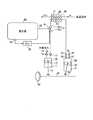
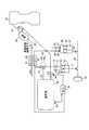
本実施例1の熱エネルギ回収装置は、高温流体の熱を利用して作動流体を断熱圧縮→等圧受熱→断熱膨張→等圧放熱させて駆動力を得るブレイトンサイクル機関であって、図1に示す如く、吸入した作動流体を断熱圧縮する圧縮機10と、この圧縮機10にて断熱圧縮された作動流体に高温流体の熱を等圧力で吸熱させる熱交換器20と、この熱交換器20で等圧受熱された作動流体を断熱膨張させる膨張機30とを備えている。 The thermal energy recovery apparatus of the first embodiment is a Brayton cycle engine that obtains a driving force by adiabatic compression → isobaric heat reception → adiabatic expansion → isobaric heat dissipation by using heat of a high-temperature fluid, and FIG. As shown in FIG. 1, a
ここでは、その高温流体として内燃機関(図示略)から排出された排気ガスを使用し、その排気ガスの排気熱を回収して機械エネルギへと変換させる。即ち、ここで例示する熱エネルギ回収装置は、内燃機関の排気熱を回収する排気熱回収装置である。また、本実施例1にあっては、圧縮機10へと吸入される作動流体として空気等の気体(以下「作動ガス」という。)を例示する。 Here, exhaust gas discharged from an internal combustion engine (not shown) is used as the high-temperature fluid, and the exhaust heat of the exhaust gas is recovered and converted into mechanical energy. That is, the thermal energy recovery device exemplified here is an exhaust heat recovery device that recovers exhaust heat of the internal combustion engine. In the first embodiment, a gas such as air (hereinafter referred to as “working gas”) is exemplified as the working fluid sucked into the
先ず、本実施例1の熱交換器20について説明する。 First, the
この熱交換器20は、高温流体が流れる第1流路21と、圧縮機10で断熱圧縮された作動ガスが流れる第2流路22とを備えている。ここで、その第1及び第2の流路21,22は、作動ガスへの吸熱効率(熱交換器効率)を高める為に高温流体の流れ方向と作動ガスの流れ方向とが逆になるよう配置することが好ましい。 The
ここでは内燃機関の排気ガスを高温流体として利用するので、本実施例1の熱交換器20は、その排気ガスを第1流路21に流入させるよう図1に示す内燃機関の排気通路80上に配置されている。ここで、その排気ガスの排気熱を有効利用する為には、熱交換器20が可能な限り内燃機関の燃焼室に近い位置(排気通路80の上流側)へ配置されることが好ましい。そこで、本実施例1の熱交換器20は、例えば排気マニホルドの集合部分に配置する。 Here, since the exhaust gas of the internal combustion engine is used as a high-temperature fluid, the
続いて、本実施例1の圧縮機10について説明する。 Next, the
この圧縮機10は、容積Vcompが一定のシリンダ11と、このシリンダ11内を往復運動するピストン12とを備えている。このピストン12は、コネクティングロッド13を介してクランクシャフト40に連結される。尚、そのクランクシャフト40には、フライホイール50が配設されている。The
また、この圧縮機10には、大気圧の作動ガスをシリンダ11内に導く吸気流路14と、そのシリンダ11内でピストン12により断熱圧縮された作動ガスを熱交換器20の第2流路22へと導く排気流路15とが設けられており、その夫々に吸気側開閉弁16と排気側開閉弁17が配備されている。 Further, the
ここで、その吸気側開閉弁16としては、吸気流路14とシリンダ11内の圧力差により作動ガスをシリンダ11内に流入させる一方、その作動ガスの吸気流路14への逆流を防ぐ逆止弁(吸気側リード弁)を用いる。また、排気側開閉弁17としては、排気流路15とシリンダ11内の圧力差により断熱圧縮後の作動ガスを熱交換器20の第2流路22に流入させる一方、シリンダ11内への逆流を防ぐ逆止弁(排気側リード弁)を用いる。 Here, as the intake-side on-off
続いて、上記膨張機30について説明する。 Next, the
この膨張機30は、容積Vexp(ここではVexp≧Vcomp)が一定のシリンダ31と、このシリンダ31内を往復運動するピストン32とを備えている。このピストン32は、コネクティングロッド33を介して圧縮機10と同一のクランクシャフト40に連結される。The
また、この膨張機30には、熱交換器20で等圧受熱された作動ガスをシリンダ31内に導く吸気流路34と、断熱膨張後の作動ガスをシリンダ31の外に導く排気流路35とが設けられており、その夫々に吸気側開閉弁36と排気側開閉弁37が配備されている。 Further, the
ここで、その吸気側開閉弁36及び排気側開閉弁37としては、例えばチェーンやスプロケット等を介することによりクランクシャフト40の回転に同期して開閉動作を行う回転同期弁を用いる。 Here, as the intake-side on-off
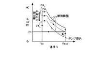
この排気熱回収装置においては、図2−1のP−V線図や図2−2のT−s線図に示す如く、圧力P1(=大気圧)の作動ガスが吸気流路14から圧縮機10のシリンダ11内に吸入され、この圧縮機10にて圧力P1,体積V1(=Vcomp),温度T1,エントロピs1の作動ガスをピストン12が断熱圧縮する。しかる後、この断熱圧縮された圧力P2,体積V2,温度T2,エントロピs1の作動ガスが排気流路15から排出され、熱交換器20で排気ガスの排気熱と等圧受熱される。In this exhaust heat recovery apparatus, as shown in the PV diagram of FIG. 2-1 and the Ts diagram of FIG. 2-2, the working gas at the pressure P1 (= atmospheric pressure) is compressed from the
そして、その等圧受熱された圧力P2,体積V3,温度T3,エントロピs2の作動ガスは、吸気流路34を介して膨張機30のシリンダ31内へと流入し、断熱膨張しながらピストン32を下降させる。その断熱膨張後の圧力P1,体積V4,温度T4,エントロピs2の作動ガスは、排気流路35を介して膨張機30から排気(等圧放熱)される。 Then, the working gas having the pressure P2, volume V3, temperature T3, and entropy s2 that has been subjected to the isobaric heat flows into the
この排気熱回収装置においては、そのようにして排気ガスの排気熱を回収し、膨張機30の断熱膨張行程においてクランクシャフト40を回転させる。 In this exhaust heat recovery device, the exhaust heat of the exhaust gas is recovered as described above, and the
ところで、この排気熱回収装置においては、その要求出力(クランクシャフト40から取り出される出力の要求値)が低いときに仕事を行うと、その仕事により取り出された出力が無駄になってしまい、熱エネルギの回収効率の悪化を招来してしまう。 By the way, in this exhaust heat recovery device, if work is performed when the required output (required value of output taken out from the crankshaft 40) is low, the output taken out by the work is wasted, and heat energy is lost. The recovery efficiency will be deteriorated.
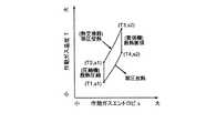
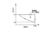
また、上述した本実施例1における圧縮機10の容積Vcompと膨張機30の容積Vexpは、熱交換器20で作動ガスが排気熱を十分に受熱できることを前提に夫々設定されている。これが為、例えば、内燃機関を一時停止させた場合や内燃機関が減速中のときのような排気熱が無い状態又は極端に少ない状態等の作動ガスの受熱容量が小さい状態においては、夫々の容積Vcomp,Vexpの均衡が崩れてしまい、図3に示す膨張機30のポンプ損失に伴った引きずり抵抗が発生してしまう。尚、その図3は、上述した膨張機30のP−V線図であって、排気熱の有無による相違を示す図である。また、そのようなポンプ損失を発生させてしまうにも拘わらず、圧縮機10は、圧縮作動ガスを生成し続けて無駄な仕事をするので、熱エネルギの回収効率が悪化してしまう。Further, the volume Vcomp of the
そこで、本実施例1にあっては、要求出力が低い場合又は作動ガスの受熱容量が小さい場合に、圧縮機10で生成された圧縮作動ガスを貯留することが可能な図1に示す蓄圧室60を設ける。この蓄圧室60は、圧縮機10の排気流路15上(具体的には第1排気流路15aと第2排気流路15bとの間)に設けた三方弁61と分流通路62を介して排気流路15に接続される。 Accordingly, in the first embodiment, when the required output is low or the heat receiving capacity of the working gas is small, the pressure accumulating chamber shown in FIG. 1 that can store the compressed working gas generated by the
その本実施例1の三方弁61は、内燃機関の制御手段たる電子制御装置(ECU)70によって切り替え動作が行われる。 The three-
具体的に説明すると、例えば、その三方弁61は、通常、第1排気流路15aと第2排気流路15bとを連通させる一方、これらと分流通路62とを遮断させている。かかる状況下において、電子制御装置70は、要求出力が低い状態又は作動ガスの受熱容量が小さい状態を検知すると、三方弁61を制御して、第1排気流路15aと分流通路62とを連通させる一方、これらと第2排気流路15bとを遮断させる。これにより、圧縮機10で生成された圧縮作動ガスが第1排気流路15a、分流通路62を介して蓄圧室60に溜められる。 More specifically, for example, the three-
ここで、その電子制御装置70は、例えば、内燃機関の機関回転数に基づいて内燃機関の一時停止状態や減速状態を判断し、「排気熱が無い状態」や「排気熱が極端に少ない状態」等の作動ガスの受熱容量が小さい状態を検知することができる。また、その電子制御装置70は、内燃機関の排気通路80上に配置された排気温センサ(図示略)の検出信号に基づいて作動ガスの受熱容量が小さい状態を検知することもできる。 Here, the
このように、本実施例1によれば、要求出力が低い状態又は作動ガスの受熱容量が小さい状態において、膨張機30への作動ガスの流入を阻止し、圧縮機10が生成した圧縮作動ガスを蓄圧室60に溜めることができる。即ち、この排気熱回収装置は、その要求出力が低い場合に従来は無駄に消費されていた圧縮機10の仕事を蓄圧室60に蓄積するので、熱エネルギの回収効率の悪化を抑制することができる。 As described above, according to the first embodiment, in a state where the required output is low or the heat receiving capacity of the working gas is small, the working gas is prevented from flowing into the
ところで、その蓄圧室60に蓄積された圧縮作動ガスは、種々の形態において利用することができる。しかしながら、その圧縮作動ガスは、供給し続けるにつれて減少し、有効利用できなくなってしまう。ここで、蓄圧室60から圧縮作動ガスが減少していくと、その内部圧力が低下する。これが為、本実施例1にあっては、蓄圧室60の内部圧力を検出する図1に示す圧力センサ63を設け、その検出信号に基づいて圧縮作動ガスの減少を電子制御装置70に検知させる。 By the way, the compressed working gas accumulated in the
以下に、その蓄圧室60に蓄積された圧縮作動ガスの利用形態について例示する。 Below, the utilization form of the compression working gas accumulate | stored in the
最初に、その圧縮作動ガスをブレイトンサイクルで利用する場合について説明する。 First, the case where the compressed working gas is used in the Brayton cycle will be described.
ここでは、蓄圧室60に貯留されている圧縮作動ガスを熱交換器20の第2流路22へと供給し、その圧縮作動ガスへの等圧受熱を行わせる。これが為、その蓄圧室60の圧縮作動ガスを供給対象たる熱交換器20の第2流路22へと導く圧縮作動ガス供給路を設ける。 Here, the compressed working gas stored in the
その圧縮作動ガス供給路は、専用のものとして蓄圧室60と第2流路22との間に配備してもよいが、ここでは既に具備されている分流通路62と第2排気流路15bとを圧縮作動ガス供給路として利用する。 The compressed working gas supply path may be provided between the
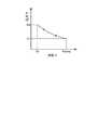
かかる場合、電子制御装置70は、例えば熱交換器20に排気熱が十分に供給される状態を検知し、且つ、蓄圧室60の内部圧力が図4に示す「PA2」以上のときに、三方弁61を制御して、第2排気流路15bと分流通路62とを連通させる一方、これらと第1排気流路15aとを遮断させる。In such a case, the
ここで、上述した内部圧力PA2とは、それよりも低い内部圧力(例えば、図4に示す内部圧力PA3)のときに蓄圧室60の圧縮作動ガスを利用すると、膨張機30においてポンプ損失を発生させてしまう蓄圧室60の内部圧力値のことをいい、そのようなポンプ損失を回避する為の閾値である。Here, the internal pressure PA2 described above is a pump loss in the
これにより、蓄圧室60における図4に示す圧力PA1の圧縮作動ガスは、熱交換器20に供給されて等圧受熱される。そして、膨張機30においては、圧力PA1の作動ガスが熱交換器20から供給されて断熱膨張を行い、クランクシャフト40を回転させる。As a result, the compressed working gas having the pressure PA1 shown in FIG. In the
一方、圧縮機10においては、上述したが如く第2排気流路15b及び分流通路62と第1排気流路15aとが遮断しているので、その第1排気流路15aへの作動ガスの排出が遮断させられている。これが為、かかる場合の圧縮機10においては、図5のP−V線図に示す如く大気圧P1及び体積Vcompの状態と圧力PB及び体積Voの状態とを繰り返すので損失が発生しない。尚、その図5における「PB」はピストン12が上死点に位置しているときの圧縮機10の圧力を示し、「Vo」はピストン12が上死点に位置しているときの圧縮機10の体積を示す。On the other hand, in the
このように、蓄圧室60に蓄積された圧縮作動ガスをブレイトンサイクルで利用する場合には、圧縮機10での仕事を無くすことができるので、効率良く排気熱の回収仕事を増加させることができる。特に、ここでは、圧縮機10から第1排気流路15aへと作動ガスを排出できなくなるので、その圧縮機10の仕事が確実に停止させられて、より効果的に効率の良い排気熱の回収仕事を行うことができる。 As described above, when the compressed working gas accumulated in the
ここで、電子制御装置70は、圧力センサ63の検出信号を参照しながら蓄圧室60の内部圧力を監視し、その内部圧力が上述した閾値PA2まで低下したときに三方弁61を制御し、第1排気流路15aと第2排気流路15bとを連通させる一方、これらと分流通路62とを遮断させる。これにより、圧縮機10が仕事を始め(圧縮作動ガスを生成し)、通常のブレイトンサイクルに復帰する。Here, the
以上示した如く、ここでは、分流通路62,第2排気流路15b,三方弁61,圧力センサ63及び電子制御装置70によって圧縮作動ガス供給手段が構成され、この圧縮作動ガス供給手段により蓄圧室60の圧縮作動ガスを熱交換器20の第2流路22へと供給する。また、その圧縮作動ガス供給手段は、上述したが如く、その蓄圧室60の圧縮作動ガスを熱交換器20の第2流路22へと供給する際に、三方弁61を制御して圧縮機10からの作動ガスの排出を遮断している。 As described above, here, the compressed working gas supply means is constituted by the
次に、蓄圧室60に蓄積された圧縮作動ガスを図6に示す内燃機関81の出力補助として利用する場合について説明する。即ち、通常の吸入空気量では内燃機関81が要求出力を満たせない場合に、蓄圧室60の圧縮作動ガス(圧縮空気)を必要量だけ燃焼室へと供給し、その要求出力を達成させる。 Next, the case where the compressed working gas accumulated in the
ここでは、図6に示す如く、蓄圧室60の圧縮作動ガス(圧縮空気)を供給対象たる内燃機関81の吸気通路82へと導く圧縮作動ガス供給路64を設け、この圧縮作動ガス供給路64上に圧縮作動ガスの流量制御弁65を設ける。また、その圧縮作動ガス供給路64は、一端を蓄圧室60の内部と連通させ、他端を逆止弁66を介して内燃機関81の吸気通路82に連通させる。その逆止弁66は、圧縮作動ガス供給路64と吸気通路82の圧力差により圧縮作動ガスを吸気通路82に流入させる一方、作動ガスの圧縮作動ガス供給路64への逆流を防ぐものである。 Here, as shown in FIG. 6, there is provided a compressed working
かかる場合、電子制御装置70は、内燃機関81が要求出力を満たすことができず、且つ、蓄圧室60の内部圧力が所定値以上のときに、流量制御弁65を制御して内燃機関81が要する量の圧縮作動ガスを吸気通路82へと供給させる。これにより、燃焼室への吸入空気量が増加するので、内燃機関81の出力が向上して要求出力を満たすことができる。 In such a case, the
ここで、その所定値とは、逆止弁66を作動させる為に要する圧力値であり、吸気通路82の圧力(例えば大気圧)よりも高い値のことをいう。 Here, the predetermined value is a pressure value required for operating the
また、流量制御弁65の制御量については、例えば、内燃機関81の出力補助に要する圧縮作動ガス量と流量制御弁65の開弁角度との関係からなるマップデータやデータベースを予め用意しておく。そして、電子制御装置70は、必要とする圧縮作動ガス量に応じた流量制御弁65の開弁角度をマップデータ等から読み込んで流量制御弁65を制御する。 For the control amount of the
尚、その際には、第1排気流路15aと第2排気流路15bとを連通させる一方、これらと分流通路62とを遮断させるように三方弁61が制御されており、通常のブレイトンサイクルを行っている。 In this case, the three-
電子制御装置70は、かかる場合においても圧力センサ63の検出信号を参照しながら蓄圧室60の内部圧力を監視しており、その内部圧力が上述した所定値まで低下したときに流量制御弁65を制御して閉弁させる。 Even in such a case, the
以上示した如く、ここでは、圧縮作動ガス供給路64,流量制御弁65,逆止弁66,圧力センサ63及び電子制御装置70によって、蓄圧室60の圧縮作動ガスを内燃機関81の吸気通路82へと供給する圧縮作動ガス供給手段が構成される。 As described above, the compressed working
次に、蓄圧室60に蓄積された圧縮作動ガスを図7に示す内燃機関81の始動時における排気流路への2次空気として利用する場合について説明する。 Next, the case where the compressed working gas accumulated in the
一般に、内燃機関81においては、排気ガス中のHC,CO,NOx等の有害物質を酸化,還元させる三元触媒等からなる図7に示す触媒コンバータ84が排気流路上に設けられている。この触媒コンバータ84は、理論空燃比付近で有害物質の十分な転化効率を得られるものであり、また、所定の温度(活性化温度)以上になることで活性化するものである。 In general, in the
ここで、内燃機関81の始動直後等の冷間時においては、暖気後と比して、一般に吸入空気温度が低く燃料の気化特性も悪化するので、燃料噴射量を増量して空燃比を理論空燃比よりも濃くしている。これが為、かかる冷間時においては、触媒コンバータ84でのHC,COの転化効率が低下するので、触媒コンバータ84通過後の排気ガス中のHC,CO濃度が高くなってしまう、という不都合が生じていた。 Here, when the
そこで、ここでは、その冷間時のHC,COを低減させる為に、触媒コンバータ84の排気ガスの流れに対する上流側の排気通路83に蓄圧室60の圧縮作動ガス(圧縮空気)を2次空気として供給する。 Therefore, here, in order to reduce HC and CO in the cold state, the compressed working gas (compressed air) in the
かかる場合においても、図7に示す如く、逆止弁66を介して蓄圧室60の圧縮作動ガス(圧縮空気)を供給対象たる排気通路83へと導く圧縮作動ガス供給路64を設け、この圧縮作動ガス供給路64上に圧縮作動ガスの流量制御弁65を設けている。 Even in such a case, as shown in FIG. 7, a compressed working
かかる場合の電子制御装置70は、例えば、内燃機関81の始動直後で、且つ、蓄圧室60の内部圧力が所定値以上のときに、流量制御弁65を制御して触媒コンバータ84の早期活性化を図り得る量の圧縮作動ガスを排気通路83へと供給させる。これにより、その触媒コンバータ84の温度が上昇して活性化し、機関始動直後におけるHC,COを低減させることができる。 In this case, the
ここで、その所定値とは、逆止弁66を作動させる為に要する圧力値であり、排気通路83の圧力よりも高い値のことをいう。 Here, the predetermined value is a pressure value required to operate the
また、流量制御弁65の制御量については、例えば、触媒コンバータ84の床温と当該触媒コンバータ84を活性温度まで上昇させ得る圧縮作動ガス量と流量制御弁65の開弁角度との関係からなるマップデータやデータベースを予め用意しておく。そして、電子制御装置70は、必要とする圧縮作動ガス量に応じた流量制御弁65の開弁角度をマップデータ等から読み込んで流量制御弁65を制御する。 The control amount of the
尚、ここでも、その際には、第1排気流路15aと第2排気流路15bとを連通させる一方、これらと分流通路62とを遮断させるように三方弁61が制御されており、通常のブレイトンサイクルを行っている。 Here, also in this case, the three-
以上示した如く、ここでは、圧縮作動ガス供給路64,流量制御弁65,逆止弁66,圧力センサ63及び電子制御装置70によって、蓄圧室60の圧縮作動ガスを内燃機関81における触媒コンバータ84よりも上流側の排気通路83へと供給する圧縮作動ガス供給手段が構成される。 As described above, here, the compressed working
本発明に係る熱エネルギ回収装置の実施例2を図8から図9−2に基づいて説明する。尚、ここでも、その熱エネルギ回収装置として、内燃機関(図示略)の排気熱を回収する排気熱回収装置を例に挙げる。 Embodiment 2 of the thermal energy recovery apparatus according to the present invention will be described with reference to FIGS. 8 to 9-2. Here again, as the thermal energy recovery device, an exhaust heat recovery device that recovers exhaust heat of an internal combustion engine (not shown) is taken as an example.
本実施例2の排気熱回収装置は、前述した実施例1の排気熱回収装置において、蓄圧室60への圧縮作動ガスの貯留中に発生している膨張機30のポンプ損失を低減させたものである。 The exhaust heat recovery apparatus according to the second embodiment is the exhaust heat recovery apparatus according to the first embodiment described above, in which the pump loss of the
ここで、図3における膨張機30のポンプ損失の拡大図を図9−1に示す。その図3及び図9−1の「P1」は大気圧を示し、「Pa」は負圧を示す。また、「Vo」はピストン32が上死点に位置しているときの膨張機30の体積を示し、「Vexp」はピストン32が下死点に位置しているときの膨張機30の体積を示す。Here, an enlarged view of the pump loss of the
この図3及び図9−1から明らかなように、「排気熱が無い状態」又は「排気熱が極端に少ない状態」等の作動ガスの受熱容量が小さい状態においては、ピストン32が下死点に位置しているときに膨張機30が負圧Paとなり、クランクシャフト40の回転に同期して排気側開閉弁37が開弁した際に体積Vexp一定のまま即座に膨張機30が大気圧P1になる。しかる後、この膨張機30は、大気圧P1のままピストン32が上死点へと移動する。As apparent from FIGS. 3 and 9-1, in a state where the heat receiving capacity of the working gas is small, such as “the state where there is no exhaust heat” or “the state where the exhaust heat is extremely low”, the
このように、膨張機30におけるポンプ損失は、排気側開閉弁37が開弁した際に即座に大気圧P1になることによって大きくなってしまう。 Thus, the pump loss in the
そこで、本実施例2では、そのポンプ損失を低減させる為に、前述した実施例1の排気熱回収装置において、作動ガスの受熱容量が小さい場合で且つ蓄圧室60への圧縮作動ガスの貯留中に膨張機30からの作動ガスの排出を遮断可能な遮断手段を設ける。具体的には、図8に示す如く、膨張機30の排気流路35における排気側開閉弁37の下流側に電子制御装置70で開閉動作可能な開閉弁38を設ける。その開閉弁38は、通常は開状態になっており、作動ガスの受熱容量が小さい場合で且つ蓄圧室60に圧縮作動ガスを貯留している状態のときに閉弁させる。 Therefore, in the second embodiment, in order to reduce the pump loss, in the exhaust heat recovery apparatus of the first embodiment described above, when the heat receiving capacity of the working gas is small and the compressed working gas is being stored in the
ここで、かかる開閉弁38の閉弁制御を行ったとしても、膨張機30は、図9−2に示す如く、ピストン32が下死点に位置しているときに負圧Paになる。しかしながら、ここでは、その後に排気側開閉弁37がクランクシャフト40の回転と同期して開弁した際に排気側開閉弁37の下流側の開閉弁38が閉弁されているので、排気流路35内における開閉弁38までの間の残存作動ガスがシリンダ31へと負圧により流入する。これにより、膨張機30は、負圧Paから負圧Pbまで僅かに圧力上昇した後、ピストン32の上昇に伴って大気圧P1側へと圧力上昇していく。 Here, even if the valve closing control of the on-off
このように、本実施例2にあっては、作動ガスの受熱容量が小さい場合で且つ蓄圧室60に圧縮作動ガスを貯留している状態において開閉弁38を閉弁させることで、膨張機30におけるポンプ損失が大幅に低減される。 As described above, in the second embodiment, the
即ち、本実施例2の電子制御装置70は、作動ガスの受熱容量が小さい状態を検知した際に、第1排気流路15aと分流通路62とを連通させ、これらと第2排気流路15bとを遮断させるように三方弁61を制御し、更に開閉弁38を制御して閉弁させる。これにより、圧縮機10で生成された圧縮作動ガスが蓄圧室60に蓄積されると共に、膨張機30におけるポンプ損失が大幅に低減される。これが為、本実施例2の排気熱回収装置においては、熱エネルギの回収効率の悪化を更に抑制することができる。 That is, when the
ここで、本実施例2にあっても、その蓄圧室60に蓄積された圧縮作動ガスは、実施例1にて例示したが如き種々の形態において利用することができる。 Here, even in the second embodiment, the compressed working gas accumulated in the
以上のように、本発明に係る熱エネルギ回収装置は、要求出力が低い場合又は作動ガスの受熱容量が小さい場合における無駄な仕事の抑制に有用であり、特に、これによって熱エネルギの回収効率の悪化を抑制させる技術に適している。 As described above, the thermal energy recovery device according to the present invention is useful for suppressing useless work when the required output is low or when the heat receiving capacity of the working gas is small. Suitable for technology to suppress deterioration.
10 圧縮機
11 シリンダ
12 ピストン
14 吸気流路
15 排気流路
15a 第1排気流路
15b 第2排気流路
16 吸気側開閉弁
17 排気側開閉弁
20 熱交換器
30 膨張機
31 シリンダ
32 ピストン
34 吸気流路
35 排気流路
36 吸気側開閉弁
37 排気側開閉弁
38 開閉弁
60 蓄圧室
61 三方弁
62 分流通路
63 圧力センサ
64 圧縮作動ガス供給路
65 流量制御弁
66 逆止弁
70 電子制御装置(ECU)
80 排気通路
81 内燃機関
82 吸気通路
83 排気通路
84 触媒コンバータDESCRIPTION OF
80
Claims (6)
Translated fromJapanese要求出力が低い場合又は作動ガスの受熱容量が小さい場合に前記圧縮機で圧縮された作動ガスを貯留する蓄圧室を設けたことを特徴とする熱エネルギ回収装置。A compressor having a piston for compressing the sucked working gas, a heat exchanger for absorbing the heat of the high-temperature fluid into the working gas compressed by the compressor, and being pushed by the expansion of the absorbed working gas An expander with a piston,
A thermal energy recovery device comprising a pressure accumulating chamber for storing the working gas compressed by the compressor when the required output is low or the heat receiving capacity of the working gas is small.
Priority Applications (3)
| Application Number | Priority Date | Filing Date | Title |
|---|---|---|---|
| JP2005106310AJP4497015B2 (en) | 2005-04-01 | 2005-04-01 | Thermal energy recovery device |
| US11/366,438US7448213B2 (en) | 2005-04-01 | 2006-03-03 | Heat energy recovery apparatus |
| EP06111110.0AEP1752613B1 (en) | 2005-04-01 | 2006-03-14 | Heat energy recovery apparatus |
Applications Claiming Priority (1)
| Application Number | Priority Date | Filing Date | Title |
|---|---|---|---|
| JP2005106310AJP4497015B2 (en) | 2005-04-01 | 2005-04-01 | Thermal energy recovery device |
Publications (2)
| Publication Number | Publication Date |
|---|---|
| JP2006283698A JP2006283698A (en) | 2006-10-19 |
| JP4497015B2true JP4497015B2 (en) | 2010-07-07 |
Family
ID=37068710
Family Applications (1)
| Application Number | Title | Priority Date | Filing Date |
|---|---|---|---|
| JP2005106310AExpired - Fee RelatedJP4497015B2 (en) | 2005-04-01 | 2005-04-01 | Thermal energy recovery device |
Country Status (3)
| Country | Link |
|---|---|
| US (1) | US7448213B2 (en) |
| EP (1) | EP1752613B1 (en) |
| JP (1) | JP4497015B2 (en) |
Families Citing this family (53)
| Publication number | Priority date | Publication date | Assignee | Title |
|---|---|---|---|---|
| FR2891347B1 (en)* | 2005-09-28 | 2007-11-02 | Air Liquide | METHOD AND DEVICE FOR FILLING A PRESSURIZED GAS IN A RESERVOIR |
| FR2905728B1 (en)* | 2006-09-11 | 2012-11-16 | Frederic Thevenod | HYBRID ENGINE WITH EXHAUST HEAT RECOVERY |
| US7533530B2 (en)* | 2007-01-19 | 2009-05-19 | Courtright Geoffrey B | Engine for the efficient production of an energized fluid |
| US20100269502A1 (en)* | 2007-01-22 | 2010-10-28 | Edward Lawrence Warren | External combustion engine |
| FR2914696A1 (en)* | 2007-04-03 | 2008-10-10 | Etienne Baudino | Motorized hybrid system for motor vehicle, has external combustion engine with pistons animated by detenting and expansion of fluid in cylinders, where fluid is heated under external combustion engine upstream pressure by combustion gases |
| CN101883913B (en)* | 2007-10-03 | 2013-09-11 | 等熵有限公司 | energy storage device |
| FR2922608B1 (en)* | 2007-10-19 | 2009-12-11 | Saipem Sa | INSTALLATION AND METHOD FOR STORING AND RETURNING ELECTRIC ENERGY USING PISTON GAS COMPRESSION AND RELIEF UNIT |
| US8037678B2 (en) | 2009-09-11 | 2011-10-18 | Sustainx, Inc. | Energy storage and generation systems and methods using coupled cylinder assemblies |
| US8250863B2 (en) | 2008-04-09 | 2012-08-28 | Sustainx, Inc. | Heat exchange with compressed gas in energy-storage systems |
| US8677744B2 (en) | 2008-04-09 | 2014-03-25 | SustaioX, Inc. | Fluid circulation in energy storage and recovery systems |
| US20100307156A1 (en) | 2009-06-04 | 2010-12-09 | Bollinger Benjamin R | Systems and Methods for Improving Drivetrain Efficiency for Compressed Gas Energy Storage and Recovery Systems |
| US7832207B2 (en) | 2008-04-09 | 2010-11-16 | Sustainx, Inc. | Systems and methods for energy storage and recovery using compressed gas |
| US8240140B2 (en) | 2008-04-09 | 2012-08-14 | Sustainx, Inc. | High-efficiency energy-conversion based on fluid expansion and compression |
| US8474255B2 (en) | 2008-04-09 | 2013-07-02 | Sustainx, Inc. | Forming liquid sprays in compressed-gas energy storage systems for effective heat exchange |
| US8448433B2 (en) | 2008-04-09 | 2013-05-28 | Sustainx, Inc. | Systems and methods for energy storage and recovery using gas expansion and compression |
| US8225606B2 (en) | 2008-04-09 | 2012-07-24 | Sustainx, Inc. | Systems and methods for energy storage and recovery using rapid isothermal gas expansion and compression |
| US8359856B2 (en) | 2008-04-09 | 2013-01-29 | Sustainx Inc. | Systems and methods for efficient pumping of high-pressure fluids for energy storage and recovery |
| US7958731B2 (en) | 2009-01-20 | 2011-06-14 | Sustainx, Inc. | Systems and methods for combined thermal and compressed gas energy conversion systems |
| US8479505B2 (en) | 2008-04-09 | 2013-07-09 | Sustainx, Inc. | Systems and methods for reducing dead volume in compressed-gas energy storage systems |
| WO2009152141A2 (en) | 2008-06-09 | 2009-12-17 | Sustainx, Inc. | System and method for rapid isothermal gas expansion and compression for energy storage |
| JP2010128169A (en)* | 2008-11-27 | 2010-06-10 | Furukawa Electric Co Ltd:The | Optical fiber cable |
| US7963110B2 (en) | 2009-03-12 | 2011-06-21 | Sustainx, Inc. | Systems and methods for improving drivetrain efficiency for compressed gas energy storage |
| US8104274B2 (en) | 2009-06-04 | 2012-01-31 | Sustainx, Inc. | Increased power in compressed-gas energy storage and recovery |
| US8196395B2 (en) | 2009-06-29 | 2012-06-12 | Lightsail Energy, Inc. | Compressed air energy storage system utilizing two-phase flow to facilitate heat exchange |
| US8247915B2 (en) | 2010-03-24 | 2012-08-21 | Lightsail Energy, Inc. | Energy storage system utilizing compressed gas |
| US8436489B2 (en) | 2009-06-29 | 2013-05-07 | Lightsail Energy, Inc. | Compressed air energy storage system utilizing two-phase flow to facilitate heat exchange |
| US8146354B2 (en) | 2009-06-29 | 2012-04-03 | Lightsail Energy, Inc. | Compressed air energy storage system utilizing two-phase flow to facilitate heat exchange |
| WO2011056855A1 (en) | 2009-11-03 | 2011-05-12 | Sustainx, Inc. | Systems and methods for compressed-gas energy storage using coupled cylinder assemblies |
| US9003788B2 (en)* | 2009-11-20 | 2015-04-14 | GM Global Technology Operations LLC | Vehicle energy harvesting device having a continuous loop of shape memory alloy |
| US8191362B2 (en) | 2010-04-08 | 2012-06-05 | Sustainx, Inc. | Systems and methods for reducing dead volume in compressed-gas energy storage systems |
| US8171728B2 (en) | 2010-04-08 | 2012-05-08 | Sustainx, Inc. | High-efficiency liquid heat exchange in compressed-gas energy storage systems |
| US8234863B2 (en) | 2010-05-14 | 2012-08-07 | Sustainx, Inc. | Forming liquid sprays in compressed-gas energy storage systems for effective heat exchange |
| US8726661B2 (en) | 2010-08-09 | 2014-05-20 | GM Global Technology Operations LLC | Hybrid powertrain system including an internal combustion engine and a stirling engine |
| US8495872B2 (en) | 2010-08-20 | 2013-07-30 | Sustainx, Inc. | Energy storage and recovery utilizing low-pressure thermal conditioning for heat exchange with high-pressure gas |
| DE102010042401A1 (en)* | 2010-10-13 | 2012-04-19 | Robert Bosch Gmbh | Device and method for waste heat utilization of an internal combustion engine |
| US8578708B2 (en) | 2010-11-30 | 2013-11-12 | Sustainx, Inc. | Fluid-flow control in energy storage and recovery systems |
| US9109614B1 (en) | 2011-03-04 | 2015-08-18 | Lightsail Energy, Inc. | Compressed gas energy storage system |
| WO2012138948A1 (en)* | 2011-04-08 | 2012-10-11 | Scuderi Group, Llc | Air management system for air hybrid engine |
| JP2014522460A (en)* | 2011-05-17 | 2014-09-04 | サステインエックス, インコーポレイテッド | System and method for efficient two-phase heat transfer in a compressed air energy storage system |
| DE102011107885A1 (en)* | 2011-07-18 | 2013-01-24 | Gaby Traute Reinhardt | Device for production and storage of e.g. wind power in hydro-electric power plant, has piston engine reversibly operated by gas delivered from pressure reservoir and connected with generator for power production |
| US8613267B1 (en) | 2011-07-19 | 2013-12-24 | Lightsail Energy, Inc. | Valve |
| EP2574865A1 (en)* | 2011-09-29 | 2013-04-03 | Siemens Aktiengesellschaft | Energy storage device and energy storage method |
| US20130091836A1 (en) | 2011-10-14 | 2013-04-18 | Sustainx, Inc. | Dead-volume management in compressed-gas energy storage and recovery systems |
| EP2751391A4 (en) | 2011-10-18 | 2015-04-22 | Lightsail Energy Inc | Compressed gas energy storage system |
| WO2013138667A1 (en)* | 2012-03-16 | 2013-09-19 | Lightsail Energy Inc. | Compressed gas system employing hydraulic motor for energy capture |
| EP2738360B1 (en)* | 2012-12-03 | 2019-06-12 | General Electric Technology GmbH | A warming arrangement for a steam turbine in a power plant |
| ITFI20120273A1 (en)* | 2012-12-07 | 2014-06-08 | Nuovo Pignone Srl | "A CONCENTRATED SOLAR THERMAL POWER PLANT AND METHOD" |
| US9541027B2 (en) | 2014-07-11 | 2017-01-10 | Caterpillar Inc. | System and method for recovering waste heat |
| JP6411221B2 (en)* | 2014-08-27 | 2018-10-24 | 株式会社神戸製鋼所 | Compressed fluid storage generator |
| FR3032234B1 (en)* | 2015-01-30 | 2020-01-17 | Vianney Rabhi | THERMAL MOTOR WITH TRANSFER-RELAXATION AND REGENERATION |
| GB201611171D0 (en)* | 2016-06-28 | 2016-08-10 | Exergyn Ltd | SMA bundle piston cushioning system for use in an energy recovery device |
| US11428445B2 (en)* | 2019-09-05 | 2022-08-30 | Gridworthy Technologies LLC | System and method of pumped heat energy storage |
| EP4025778B1 (en)* | 2019-09-05 | 2025-08-13 | Mulligan, Karl Peter | Systems and methods for a piston engine including a recirculating system using supercritical carbon dioxide |
Family Cites Families (27)
| Publication number | Priority date | Publication date | Assignee | Title |
|---|---|---|---|---|
| GB127686A (en) | 1918-03-21 | 1919-05-21 | Frederick William Lanchester | Improvements in and relating to Hot Air Engines. |
| GB766703A (en) | 1954-07-13 | 1957-01-23 | Charles Edmund Johnson | Improvements in or relating to air cooled internal combustion engines and to the utilization of waste heat thereof |
| US3708979A (en)* | 1971-04-12 | 1973-01-09 | Massachusetts Inst Technology | Circuital flow hot gas engines |
| US4369623A (en) | 1975-03-14 | 1983-01-25 | Johnson David E | Positive displacement engine with separate combustion chamber |
| CA1074576A (en)* | 1975-03-14 | 1980-04-01 | David E. Johnson | Positive displacement engine with separate combustion chamber |
| JPS5845565B2 (en)* | 1977-11-28 | 1983-10-11 | 工業技術院長 | Accumulated pressure heating drive device |
| JPH03149322A (en)* | 1989-11-02 | 1991-06-25 | Daikin Ind Ltd | energy storage device |
| DE4041628A1 (en) | 1990-12-22 | 1992-07-02 | Daimler Benz Ag | MIX-COMPRESSING COMBUSTION ENGINE WITH SECONDARY AIR INLET AND WITH AIR MEASUREMENT IN THE SUCTION PIPE |
| JPH0526053A (en)* | 1991-07-22 | 1993-02-02 | Hitachi Ltd | Gas turbine power plant using stored compressed air |
| JPH06257462A (en) | 1993-03-09 | 1994-09-13 | Rikagaku Kenkyusho | Engine |
| KR100271467B1 (en)* | 1996-12-12 | 2000-11-15 | 정몽규 | Low speed compensation device for turbo charger |
| JP3787978B2 (en)* | 1997-09-12 | 2006-06-21 | いすゞ自動車株式会社 | Clutch connection / disconnection device |
| US7152027B2 (en)* | 1998-02-17 | 2006-12-19 | National Instruments Corporation | Reconfigurable test system |
| US7016811B2 (en)* | 2001-08-15 | 2006-03-21 | National Instruments Corporation | Network-based system for configuring a programmable hardware element in a measurement system using hardware configuration programs generated based on a user specification |
| EP1422378B1 (en) | 1998-07-31 | 2005-09-21 | The Texas A & M University System | Gerotor compressor and gerotor expander |
| BR9912651A (en)* | 1998-07-31 | 2001-05-02 | Texas A & M Univ Sys | Quasi-isothermal brayton cycle engine |
| US6223142B1 (en)* | 1998-11-09 | 2001-04-24 | International Business Machines Corporation | Method and system for incrementally compiling instrumentation into a simulation model |
| US6212491B1 (en)* | 1998-11-09 | 2001-04-03 | International Business Machines Corporation | Automatic adjustment for counting instrumentation |
| US6216462B1 (en) | 1999-07-19 | 2001-04-17 | The United States Of America As Represented By The Administrator Of The Environmental Protection Agency | High efficiency, air bottoming engine |
| US20020128809A1 (en)* | 2000-12-30 | 2002-09-12 | International Business Machines Corporation | Randomized simulation model instrumentation |
| US6920418B2 (en)* | 2000-12-30 | 2005-07-19 | International Business Machines Corporation | Detecting events within simulation models |
| JP2002266701A (en) | 2001-03-09 | 2002-09-18 | Honda Motor Co Ltd | Exhaust heat energy recovery system for internal combustion engine |
| DE10135303A1 (en) | 2001-07-19 | 2003-02-13 | Bosch Gmbh Robert | Method and device for exhaust gas aftertreatment in internal combustion engines |
| US6672063B1 (en)* | 2002-09-25 | 2004-01-06 | Richard Alan Proeschel | Reciprocating hot air bottom cycle engine |
| JP2004251224A (en) | 2003-02-21 | 2004-09-09 | Hitachi Ltd | Engine secondary air supply |
| GB2402169B (en) | 2003-05-28 | 2005-08-10 | Lotus Car | An engine with a plurality of operating modes including operation by compressed air |
| US7140182B2 (en)* | 2004-06-14 | 2006-11-28 | Edward Lawrence Warren | Energy storing engine |
- 2005
- 2005-04-01JPJP2005106310Apatent/JP4497015B2/ennot_activeExpired - Fee Related
- 2006
- 2006-03-03USUS11/366,438patent/US7448213B2/ennot_activeExpired - Fee Related
- 2006-03-14EPEP06111110.0Apatent/EP1752613B1/ennot_activeNot-in-force
Also Published As
| Publication number | Publication date |
|---|---|
| EP1752613A2 (en) | 2007-02-14 |
| EP1752613A3 (en) | 2007-05-02 |
| JP2006283698A (en) | 2006-10-19 |
| US7448213B2 (en) | 2008-11-11 |
| EP1752613B1 (en) | 2016-04-27 |
| US20060218924A1 (en) | 2006-10-05 |
Similar Documents
| Publication | Publication Date | Title |
|---|---|---|
| JP4497015B2 (en) | Thermal energy recovery device | |
| KR101058766B1 (en) | Hydrogen Engine Using Recirculating Working Medium | |
| JP5042298B2 (en) | Internal combustion engine | |
| US8069651B2 (en) | Machine, engine system and operating method | |
| JP2009103093A (en) | Diesel engine control device | |
| WO2013046853A1 (en) | Waste heat regeneration system | |
| US11136905B2 (en) | Rankine power system with working fluid tank and control system | |
| JP2014009634A (en) | Control device of cooling system | |
| US20170130612A1 (en) | System for a heat energy recovery | |
| JP2013117319A (en) | Thermoacoustic pump | |
| JP2007187139A (en) | Waste heat recovery device | |
| JP4640184B2 (en) | Internal combustion engine | |
| WO2014183636A1 (en) | Supercritical internal-combustion direct-current steam engine unit | |
| RU2417327C2 (en) | Drive unit with ice and uncontrolled automatically-started piston machine | |
| JP5151861B2 (en) | Exhaust gas purification system and exhaust gas purification method | |
| JP4736857B2 (en) | Thermal energy recovery device | |
| JP4622819B2 (en) | Thermal energy recovery device | |
| JP4214996B2 (en) | Waste heat recovery device | |
| JP4577261B2 (en) | Thermal energy recovery device | |
| JP2009127476A (en) | Stirling engine | |
| JP2010121596A (en) | Exhaust emission control system | |
| JP4872824B2 (en) | Exhaust gas recirculation device for internal combustion engine | |
| US20190234269A1 (en) | Exhaust emission control device for internal combustion engine | |
| US11428131B2 (en) | Exhaust-gas aftertreatment arrangement | |
| JP2005351223A (en) | Thermoacoustic engine |
Legal Events
| Date | Code | Title | Description |
|---|---|---|---|
| A621 | Written request for application examination | Free format text:JAPANESE INTERMEDIATE CODE: A621 Effective date:20080318 | |
| A977 | Report on retrieval | Free format text:JAPANESE INTERMEDIATE CODE: A971007 Effective date:20090709 | |
| A131 | Notification of reasons for refusal | Free format text:JAPANESE INTERMEDIATE CODE: A131 Effective date:20090908 | |
| TRDD | Decision of grant or rejection written | ||
| A01 | Written decision to grant a patent or to grant a registration (utility model) | Free format text:JAPANESE INTERMEDIATE CODE: A01 Effective date:20100323 | |
| A01 | Written decision to grant a patent or to grant a registration (utility model) | Free format text:JAPANESE INTERMEDIATE CODE: A01 | |
| A61 | First payment of annual fees (during grant procedure) | Free format text:JAPANESE INTERMEDIATE CODE: A61 Effective date:20100405 | |
| FPAY | Renewal fee payment (event date is renewal date of database) | Free format text:PAYMENT UNTIL: 20130423 Year of fee payment:3 | |
| R151 | Written notification of patent or utility model registration | Ref document number:4497015 Country of ref document:JP Free format text:JAPANESE INTERMEDIATE CODE: R151 | |
| FPAY | Renewal fee payment (event date is renewal date of database) | Free format text:PAYMENT UNTIL: 20130423 Year of fee payment:3 | |
| LAPS | Cancellation because of no payment of annual fees |