JP4496019B2 - Method for reducing transmission of image streams taken in vivo - Google Patents
Method for reducing transmission of image streams taken in vivoDownload PDFInfo
- Publication number
- JP4496019B2 JP4496019B2JP2004188119AJP2004188119AJP4496019B2JP 4496019 B2JP4496019 B2JP 4496019B2JP 2004188119 AJP2004188119 AJP 2004188119AJP 2004188119 AJP2004188119 AJP 2004188119AJP 4496019 B2JP4496019 B2JP 4496019B2
- Authority
- JP
- Japan
- Prior art keywords
- image
- image data
- data
- reduction method
- transmission
- Prior art date
- Legal status (The legal status is an assumption and is not a legal conclusion. Google has not performed a legal analysis and makes no representation as to the accuracy of the status listed.)
- Expired - Fee Related
Links
Images


Classifications
- A—HUMAN NECESSITIES
- A61—MEDICAL OR VETERINARY SCIENCE; HYGIENE
- A61B—DIAGNOSIS; SURGERY; IDENTIFICATION
- A61B1/00—Instruments for performing medical examinations of the interior of cavities or tubes of the body by visual or photographical inspection, e.g. endoscopes; Illuminating arrangements therefor
- A61B1/04—Instruments for performing medical examinations of the interior of cavities or tubes of the body by visual or photographical inspection, e.g. endoscopes; Illuminating arrangements therefor combined with photographic or television appliances
- A61B1/041—Capsule endoscopes for imaging
- A—HUMAN NECESSITIES
- A61—MEDICAL OR VETERINARY SCIENCE; HYGIENE
- A61B—DIAGNOSIS; SURGERY; IDENTIFICATION
- A61B1/00—Instruments for performing medical examinations of the interior of cavities or tubes of the body by visual or photographical inspection, e.g. endoscopes; Illuminating arrangements therefor
- A61B1/04—Instruments for performing medical examinations of the interior of cavities or tubes of the body by visual or photographical inspection, e.g. endoscopes; Illuminating arrangements therefor combined with photographic or television appliances
- H—ELECTRICITY
- H04—ELECTRIC COMMUNICATION TECHNIQUE
- H04N—PICTORIAL COMMUNICATION, e.g. TELEVISION
- H04N19/00—Methods or arrangements for coding, decoding, compressing or decompressing digital video signals
- H04N19/50—Methods or arrangements for coding, decoding, compressing or decompressing digital video signals using predictive coding
- H04N19/503—Methods or arrangements for coding, decoding, compressing or decompressing digital video signals using predictive coding involving temporal prediction
- H04N19/507—Methods or arrangements for coding, decoding, compressing or decompressing digital video signals using predictive coding involving temporal prediction using conditional replenishment
- A—HUMAN NECESSITIES
- A61—MEDICAL OR VETERINARY SCIENCE; HYGIENE
- A61B—DIAGNOSIS; SURGERY; IDENTIFICATION
- A61B5/00—Measuring for diagnostic purposes; Identification of persons
- A61B5/0002—Remote monitoring of patients using telemetry, e.g. transmission of vital signals via a communication network
- A61B5/0031—Implanted circuitry
Landscapes
- Health & Medical Sciences (AREA)
- Life Sciences & Earth Sciences (AREA)
- Surgery (AREA)
- Engineering & Computer Science (AREA)
- Biomedical Technology (AREA)
- Molecular Biology (AREA)
- Pathology (AREA)
- Radiology & Medical Imaging (AREA)
- Nuclear Medicine, Radiotherapy & Molecular Imaging (AREA)
- Biophysics (AREA)
- Physics & Mathematics (AREA)
- Heart & Thoracic Surgery (AREA)
- Medical Informatics (AREA)
- Optics & Photonics (AREA)
- Animal Behavior & Ethology (AREA)
- General Health & Medical Sciences (AREA)
- Public Health (AREA)
- Veterinary Medicine (AREA)
- Multimedia (AREA)
- Signal Processing (AREA)
- Endoscopes (AREA)
- Studio Devices (AREA)
- Compression Or Coding Systems Of Tv Signals (AREA)
Description
Translated fromJapanese 発明の分野
この発明は画像データ伝送に関し、特に、画像データの伝送を減らすための装置、システムおよび方法に関する。The present invention relates to image data transmission, and more particularly to an apparatus, system and method for reducing transmission of image data.
発明の背景
体内の通路または腔の生体内画像化を実行し、画像情報以外の情報または画像情報に加えた情報(たとえば温度情報、圧力情報)を集めるための装置、システムおよび方法は当該技術において公知であり得る。このような装置は、中でも、様々な体内腔において画像化を行なうための様々な内視鏡画像化システムおよび装置を含み得る。BACKGROUND OF THE INVENTION Devices, systems, and methods for performing in-vivo imaging of a passage or cavity in a body and collecting information other than image information or information in addition to image information (eg, temperature information, pressure information) are known in the art. It can be known. Such devices can include, among other things, various endoscopic imaging systems and devices for imaging in various body lumens.
生体内画像化装置は、たとえば、胃腸(GI)管などの体腔または管腔の内部から画像を得るための画像化システムを含み得る。画像化システムはたとえば、光学系に関連付けられる撮像装置、随意には照明ユニット、電源、送信機およびアンテナを含み得る。他の種類の生体内装置、たとえば、送信機を必要としなくてもよい内視鏡や画像化以外の機能を果たす生体内装置が存在する。 In vivo imaging devices may include an imaging system for obtaining images from within a body cavity or lumen, such as, for example, a gastrointestinal (GI) tract. The imaging system may include, for example, an imaging device associated with the optical system, optionally a lighting unit, a power source, a transmitter and an antenna. There are other types of in-vivo devices such as endoscopes that do not require a transmitter and in-vivo devices that perform functions other than imaging.
生体内画像化装置が実行する様々な動作は、たとえば装置内の電源によって供給されるエネルギを消費し得る。典型的には、画像を確実に伝送するのにかなりのエネルギ量が消費される可能性がある。確実な画像の伝送に伴う他の「費用」または方策が用いられてもよく、たとえばデータ圧縮、エラー検出および/またはエラー訂正のためのアルゴリズムおよび/またはプロセスの実現が必要とされる可能性がある。 Various operations performed by the in-vivo imaging device may consume energy supplied by a power source within the device, for example. Typically, a significant amount of energy can be consumed to reliably transmit an image. Other “costs” or strategies associated with reliable image transmission may be used, for example, implementation of algorithms and / or processes for data compression, error detection and / or error correction may be required. is there.
発明の概要
この発明の様々な実施例は、たとえば生体内画像化装置において用い得る伝送および/または伝送に必要なエネルギを減らす画像化装置、システムおよび方法を提供する。この発明のある実施例では、先に伝送された画像に実質的に類似し得る撮影された画像は伝送され得ないか、または部分的にしか伝送され得ない。他の実施例では、画像データ以外のデータが撮影された画像の代わりに伝送され得る。SUMMARY OF THE INVENTION Various embodiments of the present invention provide imaging devices, systems and methods that reduce transmission and / or energy required for transmission that may be used, for example, in in vivo imaging devices. In certain embodiments of the present invention, captured images that may be substantially similar to previously transmitted images may not be transmitted or may be transmitted only partially. In other embodiments, data other than image data may be transmitted instead of the captured image.
この発明の主題はこの明細書の結論部分で特に指摘され、別個にクレームされる。しかしながら、この発明は、動作の構成および方法の両方については、その目的、特徴および利点と共に、添付の図面と関連して読まれると以下の詳細な説明を参照することにより最もよく理解することができる。 The subject matter of this invention is particularly pointed out in the concluding portion of this specification and is claimed separately. However, the present invention, together with its objects, features and advantages, together with its operation, features and advantages, best understood by reference to the following detailed description when read in conjunction with the accompanying drawings. it can.
説明を簡潔明瞭にするために、図に示される要素が不必要に変倍されていないことが分かるだろう。たとえば、明瞭にするためにいくつかの要素の寸法が他の要素に比べて誇張されることがある。さらに、適切に考慮する場合に、参照番号が対応する要素または類似の要素を示すために図の中で繰返される可能性がある。 It will be appreciated that the elements shown in the figures have not been unnecessarily scaled for the sake of brevity and clarity. For example, the dimensions of some elements may be exaggerated relative to other elements for clarity. Further, when considered properly, reference numerals may be repeated in the figures to indicate corresponding or similar elements.
発明の詳細な説明
以下の説明ではこの発明の様々な局面が説明される。説明する目的で、特定の構成および詳細がこの発明を完全に理解させるために述べられる。しかしながら、この発明をこの明細書中に提示される特定の詳細なしに実施し得ることも当業者には明らかとなるであろ
う。さらに、この発明を不明瞭にしないために、周知の特徴は省かれるかまたは簡略化される可能性がある。DETAILED DESCRIPTION OF THE INVENTION In the following description, various aspects of the present invention will be described. For purposes of explanation, specific configurations and details are set forth in order to provide a thorough understanding of the present invention. However, it will also be apparent to those skilled in the art that the present invention may be practiced without the specific details presented herein. Furthermore, well-known features may be omitted or simplified in order not to obscure the present invention.
この発明のある実施例が典型的には嚥下可能な生体内装置を目的としていることに留意されたい。他の実施例は嚥下可能である必要はない。この発明の実施例に従った装置は国際特許出願WO 01/65995および/または米国特許第5,604,531号に記載される実施例に類似し得、その各々はこの発明の共通の譲受人に譲渡され、引用によりこの明細書中に十分に援用される。さらに、この発明の実施例で用いるのに好適な受信および/またはディスプレイシステムはまた、WO 01/65995および/または米国特許第5,604,531号に記載される実施例に類似し得る。当然、この明細書中に記載される装置およびシステムは他の構成および他の構成要素の組を有してもよい。 Note that certain embodiments of the present invention are typically directed to swallowable in-vivo devices. Other embodiments need not be swallowable. An apparatus according to embodiments of the present invention may be similar to the embodiments described in International Patent Application WO 01/65995 and / or US Pat. No. 5,604,531, each of which is a common assignee of the present invention. And is hereby fully incorporated by reference. Furthermore, a suitable receiving and / or display system for use with embodiments of the present invention may also be similar to the embodiments described in WO 01/65995 and / or US Pat. No. 5,604,531. Of course, the devices and systems described herein may have other configurations and other sets of components.
上述の装置の実施例は、典型的には自律型であり得、典型的には自立型であり得る。たとえば、装置はカプセルまたは別のユニットであり得、この場合、すべての構成要素が容器または外殻内に実質的に収容され、装置はたとえば電力を受取ったり情報を伝送したりするためのいかなるワイヤまたはケーブルを必要としなくてもよい。装置は、たとえば、外部の受信およびディスプレイシステムと通信してデータの表示、制御または他の機能を提供し得る。たとえば、電力は内部電池または無線受信システムによって供給され得る。他の実施例は他の構成および能力を有し得る。たとえば、構成要素は複数の場所またはユニットに分散されてもよい。制御情報は外部源から受信され得る。 Embodiments of the devices described above can typically be autonomous and can typically be self-supporting. For example, the device can be a capsule or another unit, where all components are substantially contained within a container or shell, and the device can be any wire for receiving power or transmitting information, for example. Or a cable may not be required. The device may, for example, communicate with an external reception and display system to provide data display, control or other functions. For example, power can be supplied by an internal battery or a wireless reception system. Other embodiments may have other configurations and capabilities. For example, the components may be distributed across multiple locations or units. Control information may be received from an external source.
この発明の様々な実施例に従ったシステムおよび方法はいかなる好適な生体内装置と用いられてもよい。この発明の様々な実施例に従ったシステムおよび方法の代替的な実施例では、システムおよび方法は他の好適な装置、非画像化装置および/または非生体内装置と用いられてもよい。 Systems and methods according to various embodiments of the present invention may be used with any suitable in-vivo device. In alternative embodiments of systems and methods according to various embodiments of the present invention, the systems and methods may be used with other suitable devices, non-imaging devices and / or non-in vivo devices.
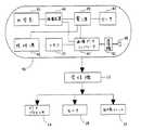
図1は、この発明の実施例に従った生体内画像化システムの概略図を示す。一実施例では、システムは、撮像装置46、照明源42および送信機41を有する装置40を含み得る。ある実施例では、装置40は嚥下可能なカプセルを用いて実現され得るが、他の種類の装置または好適な実現例を用いてもよい。患者の体外には、(たとえばアンテナまたはアンテナアレイを含む)画像受信機12、記憶ユニット19、データプロセッサ14、およびディスプレイユニットまたはモニタ18があってもよい。図1は別個のモニタを示すが、ある実施例では、画像およびその位置をともに単一のモニタを用いて示し得る。集められた画像データを記憶および/または表示する他の好適なシステムおよび方法を用いてもよい。 FIG. 1 shows a schematic diagram of an in-vivo imaging system according to an embodiment of the invention. In one example, the system may include a
ある実施例では、装置40は、データ、たとえば撮像装置46を用いて撮影される画像データを記憶するメモリおよび/または記憶ユニット77を含み得る。一実施例では、記憶ユニット77は、たとえば、撮像装置46を用いて撮影された1つの画像または複数の画像を表わすデータを記憶するのに十分な記憶容量を有し得る。代替的な実施例では、記憶ユニット77はたとえば、1つ以上の画像の画像データに関するパラメータ、たとえばヒストグラムパラメータもしくは高速フーリエ変換(FFT)パラメータおよび/または1つ以上の画像の係数、または他のパラメータもしくはデータを記憶するのに十分な記憶容量を有し得る。ある実施例では、このような記憶容量は、たとえば、1つの画像または複数の画像を記憶するのに必要とされ得る記憶容量よりも小さいかまたは著しく小さい可能性がある。 In some embodiments, the
送信機41は典型的には電波を用いて動作し得るが、装置40が内視鏡内にあるかまたは内視鏡内に組込まれる可能性のあるようなある実施例では、送信機41は、たとえばワイヤ、光ファイバおよび/または他の好適な方法によって伝送を行ない得る。 The
装置40は、典型的には自律型の嚥下可能なカプセルであり得るかまたはこれを含み得るが、他の形状であってもよく、嚥下可能または自律型である必要はない。一実施例では、装置40は、たとえばGI管腔を通るカプセルとしてGI管の画像を撮影しかつ伝送し得る、たとえば撮像装置46を含む生体内カメラを含む。典型的には、装置40は画像のストリームを撮影し得る。この発明のある実施例では、撮影された画像は、たとえば、GI管の病的状態を明らかにするのに有用であり得る。他の内腔も画像化され得る。 The
一実施例では、装置40における撮像装置46はたとえば送信機41と電気通信し得る。送信機41はたとえば画像データを画像受信機12に伝送し得る。その後、画像データは、たとえばデータプロセッサ14で処理されたり記憶ユニット19に記憶されたりディスプレイユニットまたはモニタ18に表示されたりするだろう。送信機41はたとえば制御能力も含み得るが、ただし、制御能力は別個の構成要素に含まれてもよい。送信機41は、画像および/または他のデータ(たとえば制御および/または遠隔測定データ)を受信装置に伝送することのできるいかなる好適な送信機をも含み得る。たとえば、送信機41は、おそらくはチップスケールパッケージ(CSP)に設けられる超低電力無線周波数(RF)高帯域幅送信機を含み得る。送信機41はたとえばアンテナ48を介して伝送を行なってもよい。 In one embodiment,
加えて、送信機41および/または装置40は、装置40を制御するための回路および/または機能を含み得る制御ユニットを含み得る。 In addition,
送信機41はたとえば命令を含み得るかまたはこれを処理し得る。ある実施例では、誤り訂正符号を実現する命令は、送信機41の一部であり得るかまたは送信機41に接続され得るエンコーダに含まれ得る。代替的な実施例では、このような機能はたとえば、代替的なユニット、たとえば処理ユニットに配置されてもよい。 The
典型的には、装置40は、たとえば撮像装置46によって撮影されかつ/またはメモリ77に記憶される画像データを比較する画像データコンパレータユニット47を含み得る。画像比較は、たとえば、撮像装置46によって生成される信号および/またはデータを処理することによってなされてもよい。ある実施例では、画像コンパレータユニット47は別個の構成要素である必要はなく、たとえば、画像データコンパレータユニット47またはその機能は撮像装置46または送信機41または他の好適な構成要素に一体化していてもよい。ある実施例では、画像コンパレータユニット47は、この明細書中に記載されるように比較演算、たとえば画像ストリームにおける画像間の比較、分析演算および/または判断演算を実行し得る。 Typically, the
電源45はたとえば1つ以上の電池を含み得る。たとえば、電源45は、酸化銀電池、リチウム電池、高エネルギ密度を有する他の好適な電気化学的電池などを含み得る。他の電源を用いてもよい。たとえば、内部電源45の代わりに、またはこれに加えて、外部電源(たとえば送電器)を用いて装置40に電力を送り得る。 The
データプロセッサ14は、たとえば、装置40から受信したデータを分析し得、記憶ユニット19と通信して記憶ユニット19との間で画像データをやり取りし得る。データプロセッサ14はまた、分析されたデータをモニタ18に供給し得、ここでユーザはそのデータを見ることができる。モニタ18はGI管腔の画像ならびにその画像が撮られたGI管(または画像化された他の体内腔または空洞)における位置を示し得る。一実施例では、データプロセッサ14は実時間処理するよう構成されてもよく、ならびに/または後で実行および/もしくは観察するために後処理するよう構成されてもよい。 For example, the
ある実施例では、GI管の病的状態を明らかにすることに加えて、システムはこれらの病状の場所についての情報を提供し得る。好適な位置検出システムおよび/または追跡装置ならびに位置を決定する方法は、上述の米国特許第5,604,531号、および/または2002年5月20日に出願され、「生体内信号源を配置するためのアレイシステムおよび方法」(“Array System and Method for Locating an In-Vivo Signal Source”)と題され、この発明の譲受人に譲渡され、引用によりこの明細書中に十分に援用される米国特許出願公開番号US−2002−0173718−A1の実施例に記載される。 In some embodiments, in addition to identifying the pathological state of the GI tract, the system may provide information about the location of these pathologies. A suitable position detection system and / or tracking device and method for determining position have been filed on above-mentioned US Pat. No. 5,604,531 and / or May 20, 2002, “Place in vivo signal source. United States of America, entitled “Array System and Method for Locating an In-Vivo Signal Source”, assigned to the assignee of the present invention and fully incorporated herein by reference. It is described in the examples of patent application publication number US-2002-0173718-A1.
この発明の実施例では他の位置および/または方向検出方法を用い得ることに留意されたい。一実施例では、方向情報は3つのオイラー角または四元数パラメータを含み得る。他の方向情報が用いられてもよい。一実施例では、位置および/または方向情報は、たとえば、装置40における1つ以上の送信アンテナを含みさまざまな周波数を用いてデータを伝送することにより、ならびに/または磁気手段、たとえば擬似静磁界の構成要素を用いて装置40の位置および/もしくは方向を検出することにより決定され得る。ある実施例では、たとえば外部の一定の磁界に対する位置信号を送受信し得る3つの磁気コイルを含む超音波送受信機またはモニタを用いるような方法を用いてもよい。たとえば、装置40はオプションの追跡および/または動きセンサ43を含み得る。 Note that other position and / or orientation detection methods may be used in embodiments of the invention. In one embodiment, the direction information may include three Euler angles or quaternion parameters. Other direction information may be used. In one embodiment, position and / or orientation information may be obtained, for example, by transmitting data using various frequencies, including one or more transmit antennas in
一実施例では、全地球測位システム(GPS)のようなシステム、たとえば3つ以上の局からの伝送を用いるシステムを用いてもよい。一実施例では、周波数が十分に高い(たとえば300メガヘルツ)位相および周波数を用いる場合、1ミリメートルの分解能が可能である。他の好適なGPSのようなシステムをこの発明の実施例に従って用いてもよい。たとえば、アンテナまたはセンサのアレイを腹部上または腹部近くに配置して装置40の追跡を可能にし得る。当然、他の好適な構成要素または構成要素の組をこの発明の実施例に従って用いてもよい。 In one embodiment, a system such as the Global Positioning System (GPS) may be used, such as a system that uses transmissions from more than two stations. In one embodiment, a 1 millimeter resolution is possible when using a sufficiently high phase (eg, 300 megahertz) phase and frequency. Other suitable GPS-like systems may be used in accordance with embodiments of the present invention. For example, an array of antennas or sensors may be placed on or near the abdomen to allow tracking of the
ある実施例では、装置40は、体内腔を照らすための1つ以上の照明源42、たとえば1つ以上の白色LEDまたは他のいかなる好適な光源をも含み得る。たとえば、1つ以上のレンズもしくは複合レンズアセンブリなどの1つ以上の光学素子、1つ以上の好適な光学フィルタまたは他の好適ないかなる光学素子をも含む光学系50は、反射光を撮像装置46に集中させたり他の光処理を実行したりするのに役立ち得る。 In certain embodiments, the
典型的には、装置40は、たとえば別個の部分における画像情報を伝送し得る。各部分は典型的には画像またはフレームに対応し得る。他の伝送方法が可能である。たとえば、装置40は、たとえば2分の1秒ごとに画像を撮影し得、このような画像を撮影した後に、おそらくは好適な判断または分析(たとえば伝送するかしないかの判断、または部分的な情報を伝送することの判断)後にデータを受信機12に伝送し得る。他の一定および/または可変の撮影レートおよび/または伝送レートを用いてもよく、この明細書中に述べられるように、ある画像は伝送されなくてもよい。 Typically,
典型的には、記録かつ伝送された画像データはデジタルカラー画像データであり得るが、ただし、代替的な実施例では他の画像フォーマット(たとえば白黒画像データ)を用いてもよい。一実施例では、画像データの各フレームはそれぞれ256画素を256列含み、各画素は公知の方法に従って色および輝度に対するデータを含む。たとえば、各画素においては、色は4つの複画素のモザイクによって表わすことができ、各複画素は赤、緑または青などの原色に対応する(この場合1つの原色が2度表わされる)。全体的な画素の輝度は、たとえば1バイト(たとえば0〜255)の輝度値で記録され得る。他のデータフォーマットを用いてもよい。 Typically, the recorded and transmitted image data may be digital color image data, although other image formats (eg, black and white image data) may be used in alternative embodiments. In one embodiment, each frame of image data includes 256 columns each of 256 pixels, and each pixel contains data for color and brightness according to known methods. For example, at each pixel, the color can be represented by a mosaic of four double pixels, where each double pixel corresponds to a primary color such as red, green or blue (in this case, one primary color is represented twice). The overall pixel brightness can be recorded with a brightness value of, for example, 1 byte (eg, 0-255). Other data formats may be used.
この発明の実施例は、たとえば可変レートで画像を伝送することにより、および/また
は可変フォーマットを用いてデータを伝送することによりエネルギ消費の効率を高め得る。ある実施例では、画像および/またはデータの伝送は、実質的におよび/または平均して同等の一定レートよりも低い可能性のある可変レートで実行され得る。いくつかの具体的な実施例がこの明細書中において詳細に説明されるが、この発明がこの点に関しては限定されず、このようなエネルギ効率の良い画像化装置または他の利点もしくは異なる利点を有する装置の他の実施例および/または実現例もこの発明の範囲内であることに留意されたい。さらに、異なる利点および/または他の利点はこの発明の様々な実施例に従って実現され得る。Embodiments of the present invention may increase energy consumption efficiency, for example, by transmitting images at a variable rate and / or by transmitting data using a variable format. In certain embodiments, transmission of images and / or data may be performed at a variable rate that may be substantially and / or on average lower than an equivalent constant rate. Although several specific embodiments are described in detail herein, the present invention is not limited in this regard and provides such an energy efficient imaging device or other advantages or different advantages. It should be noted that other embodiments and / or implementations of the devices having are within the scope of the present invention. Moreover, different and / or other advantages may be realized in accordance with various embodiments of the invention.
一実施例では、画像データが撮像装置46によって撮影され得た後、しかし画像が送信機41によって伝送される前に、現在撮影されている画像が先に伝送された画像に実質的に類似しているかおよび/またはこれと同一であるかどうかについて判断され得る。このような判断は、たとえば送信機41もしくは撮像装置46の一体化部分として、または装置40内の別個のユニットとして実現され得る画像コンパレータ47によってなされてもよい。たとえば送信機41の回路の一部である画像コンパレータ47はいかなる好適な態様でも実現され得る。この発明の一実施例では、現在撮影されている画像が別の画像、たとえば先に伝送された画像に実質的に類似している場合および/またはこれと同一である場合、現在撮影されている画像は伝送され得ない。そうでない場合、現在撮影されている画像は伝送され得る。ある実施例では、先に伝送された画像は直前に伝送された画像であり得るか、別の画像であり得るか、またはたとえば比較および/もしくは分析に用いられる画像データの組であり得る。典型的には、先に伝送された画像から抽出されるかまたは計算された画像データまたはデータは一時的にメモリ77に記憶され得る。この発明の他の実施例では、先に伝送された画像データ以外の画像データは、撮影された画像データとの比較のためにメモリ77に記憶され得る。さらに、代替的な実施例では、画像データ以外のデータは、比較および/または分析を含むアルゴリズムに基づいて伝送され得るかまたは伝送され得ない。 In one embodiment, after the image data can be captured by the
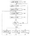
図2は、この発明の実施例に従った画像および/またはデータを伝送する方法のフローチャート図である。ブロック210に示されるように、画像はたとえば撮像装置46によって撮影され得る。ブロック215に示されるように、画像からの画像データはたとえばメモリユニット77に記憶され得る。ブロック220に示されるように、この画像はたとえば送信機41によって伝送され得る。ブロック230に示されるように、次の画像はたとえば撮像装置46によって撮影され得る。 FIG. 2 is a flowchart diagram of a method for transmitting images and / or data according to an embodiment of the present invention. As shown in
この発明の実施例では、ブロック240に示されるように、次の画像の伝送が要求され得るおよび/または所望され得るかどうかを判断する分析が実行され得る。このようなチェックおよび/または判断のためにいかなる好適な基準を用いてもよい。たとえば、一実施例では、次の画像データはメモリ77に記憶され得、ならびに次の画像が先に伝送された画像と比べて規定されたしきい値以上に異なる場合(画像間の差はこの明細書中に記載される複数の異なる方法によって判断され得る)には伝送され得る。分析のための他の好適な基準または方法をこの発明の実施例に従って用いてもよい。分析のためのいくつかの例示的な方法がこの明細書中にかつ図3に関連して詳述される。 In an embodiment of the invention, as shown at
ある実施例では、たとえば、画像データコンパレータ47を用いて、ならびに/または代替的な専用のコンパレータユニットを用いて、ならびにハードウェアおよび/もしくはソフトウェアのいかなる好適な組合せをも用いて、分析および/または比較を実行し得る。この分析および/または比較では、たとえば、サイズ、範囲、光、色、輝度、コントラスト、輪郭、余白、焦点、左右および/または上下のずれなどに関する画像間のさまざまな変化を考慮に入れることができる。たとえば、一実施例では、この分析により、たとえば画像のうち1つが他の画像よりも大きいおよび/または明るい可能性がある点を除いて
は次の画像が先に伝送された画像に実質的に類似し得るおよび/またはこれと同一であり得ると判断することができ、かつ次の画像が伝送され得ないと結論付けることができる。In some embodiments, analysis and / or using, for example, an
ブロック250に示されるように、次の画像の伝送が要求されるおよび/または所望されると判断された場合、次の画像はたとえばメモリ77に記憶され得、たとえば送信機41を用いて伝送され得る。ある実施例では、示されるように、随意には、次の画像の撮影された画像を伝送するのではなく、次の画像と最近に伝送された画像との間の差を表わすデータが伝送され得る。これは、たとえば画像間の差を検出しかつ/または表わす好適なMPEG(Moving Picture Experts Group)コーデックおよび/またはアルゴリズムを利用して実行することができる。画像間の差を表わすデータの伝送は、この発明の様々な実施例、たとえば一定の伝送レート、一定の伝送フォーマットおよび/または一定の伝送/受信システムを利用する実施例において用いることができることに留意されたい。 As shown in
代替的には、判断ブロック250に示されるように、次の画像の伝送が要求されないおよび/または所望されないと判断した場合、随意には、ブロック260に示されるようにヘッダを伝送し得るか、またはある実施例では、随意には、ブロック265に示されるように同期信号を伝送し得るか、またはある実施例では、随意には、ブロック270に示されるようにデータを伝送し得ず、伝送をスキップし得る。この発明の他の実施例では、ヘッダ、同期信号または他の好適なデータもしくは信号が画像データとともに伝送されてもよい。 Alternatively, if it is determined that transmission of the next image is not required and / or not desired, as shown in
ある実施例では、ヘッダは画像よりも含むデータが少ないかまたは著しく少ない可能性がある。一実施例では、ヘッダは、たとえばヘッダの伝送時間を示し得るデータを含み得る。この発明の他の実施例では、ヘッダは、たとえば画像化装置に対する識別子および/または記述子を含み得る。この発明のさらに他の実施例では、ヘッダは遠隔測定データ、たとえば体内の装置40の位置および/または場所を示すデータを含み得る。この発明の代替的な実施例では、ヘッダは、たとえばpHデータ、温度データ、圧力データ、電気パラメータおよび/もしくはデータ、加速データ、電源45の状態を示すデータ、位置パラメータ、照明パラメータおよび/もしくはデータ、ならびに/または他の好適なもしくは所望のデータを含み得る。ヘッダは、画像ストリーム内の伝送されない画像の通し番号または順序番号を示すデータを含み得る。ヘッダは同期データおよび/または連続データ、連続番号および/または通し番号を含み得る。このような同期信号および/またはデータがたとえば受信機12によって用いられることにより、装置40との同期を維持し得、かつ/または装置40および/もしくは電源45が動作可能であることを受信機12に示し得る。例示だけを目的として、一実施例では、ヘッダは、たとえば「画像番号753は、ローカルタイム11:53:42でGI管内の位置(14、39、26)において装置番号957によっては伝送されない」という情報を反映および/または要約するデータを含み得る。当然、ヘッダは他の内容および情報を含み得、他のデータフォーマットが用いられてもよい。 In some embodiments, the header may contain less or significantly less data than the image. In one embodiment, the header may include data that may indicate, for example, the transmission time of the header. In other embodiments of the invention, the header may include, for example, an identifier and / or descriptor for the imaging device. In yet other embodiments of the invention, the header may include telemetry data, such as data indicating the location and / or location of the
ある実施例では、伝送され得る画像データはまた、たとえば次の分析および/または次の画像との比較のために後で参照できるように一時的に記憶され得る。このような画像データは、たとえば装置40内の記憶ユニット77に記憶されてもよい。この発明のある実施例では、画像データは、たとえば1つの画像フレーム、2つ以上の画像フレーム、画像フレームの一部、および/または1つの画像フレームもしくは2つ以上の画像フレームから得られたパラメータを参照し得る。たとえば、第1の画像からの画像データがメモリ77に一時的に記憶され得さらに伝送され得、第2の画像からの画像データが画像コンパレータ47で分析され得、メモリ77に一時的に記録され得かつ伝送され得、第3の画像が撮影され得る場合、第3の画像からの画像データは第1の画像に対してではなく第2の画像からの画像データに対して分析および/または比較され得る。この発明のある実施例で
は、メモリ77に記憶される画像データは破棄されてもよく、および/または撮影されたかさもなければ得られた次の画像データに置換えられてもよい。この発明の他の実施例では、画像からの画像データは2つ以上の画像に対して分析および/または比較され得る。ある実施例では、2つ以上の画像をいかなる好適な組合せで比較してもよい。In certain embodiments, image data that may be transmitted may also be temporarily stored for later reference, eg, for subsequent analysis and / or comparison with the next image. Such image data may be stored in the storage unit 77 in the
付加的にまたは代替的には、ある実施例では、次の画像は、たとえ分析および/または比較によって次の画像の伝送が不要であると判断されても、予め規定された基準が満たされる場合、伝送され得る。一実施例では、次の画像は、予め規定された数のヘッダもしくは連続ヘッダが伝送された場合、または予め規定された数の前の画像がスキップされ、伝送されなかった場合、伝送され得る。たとえば一実施例では、次の画像は、たとえば画像ではなく10個のヘッダの連続伝送に追従する場合、または、たとえば伝送されない13個の画像に追従する場合などに伝送され得る。当然、他のしきい値および/または基準をこの発明の実施例に従って用いてもよい。加えてまたは代替的には、一実施例では、たとえば次の画像は、直前の画像の伝送から予め規定された期間が経過すれば伝送され得る。たとえば、一実施例では、次の画像は、たとえば直前の画像伝送から6秒が経過すれば伝送され得る。当然、他のしきい値および/または基準をこの発明の実施例に従って用いてもよい。 Additionally or alternatively, in certain embodiments, the next image may satisfy a predetermined criterion even though analysis and / or comparison determines that transmission of the next image is unnecessary. Can be transmitted. In one embodiment, the next image may be transmitted if a predefined number of headers or consecutive headers are transmitted, or if a predefined number of previous images are skipped and not transmitted. For example, in one embodiment, the next image may be transmitted, for example, following a continuous transmission of 10 headers instead of an image, or following 13 images that are not transmitted, for example. Of course, other thresholds and / or criteria may be used in accordance with embodiments of the invention. In addition or alternatively, in one embodiment, for example, the next image may be transmitted if a predefined period of time has elapsed since the transmission of the immediately preceding image. For example, in one embodiment, the next image may be transmitted if, for example, 6 seconds have elapsed since the last image transmission. Of course, other thresholds and / or criteria may be used in accordance with embodiments of the invention.
加えてまたは代替的には、一実施例ではたとえば、装置40が動いていないであろうことおよび/または加速していないであろうことが、たとえば動きセンサを用い、加速度計ユニットを用い、外部インピーダンスなどを測定することにより検出され得る場合、次の画像はスキップされ、伝送され得ない。これは、たとえば、装置40が比較的長時間結腸内にある場合に起こる可能性がある。ある実施例では、次の画像は、動きおよび/または加速が検出されなくても、たとえば直前の画像の伝送から予め規定された時間間隔が経過すれば伝送され得る。 In addition or alternatively, in one embodiment, for example, the
ある実施例では、ブロック250に示される伝送された画像データが圧縮され得ることに留意されたい。加えてまたは代替的には、ある実施例では、ブロック260に示される伝送されたヘッダデータまたは伝送された他のデータ(たとえば同期信号データまたは画像間の差を表わすデータ)が圧縮されてもよい。このような圧縮により、たとえば、伝送エネルギおよび/または伝送時間および/またはメモリ空間および/またはデータ記憶空間の節約が可能となるだろう。 Note that in some embodiments, the transmitted image data shown in
ある実施例では、図2のフローチャート図に示されるように、上述の動作が繰返されてもよく、かつ/または連続画像に適用されてもよい。たとえば、第3の画像が撮影され得、この第3の画像を伝送するかどうか判断する分析が実行され得る。一実施例では、この分析は、たとえば第3の画像と第2の画像の比較、または直前に伝送された画像との第3の画像の分析を含み得る。一実施例では、画像は、先に伝送された画像に実質的に類似し得るまで2分の1秒ごとに伝送され得る。当然、分析のための他の好適な方法、たとえばこの明細書中においてたとえば図3に関連して詳述される分析のための1つ以上の例示的な方法を用いてもよい。ある実施例では、画像データの代わりにヘッダが送られ得かつ付加的な画像が撮影され得る場合、この付加的な画像はたとえば直前に撮影された画像ではなく直前に伝送された画像と比較され得ることに留意されたい。ある実施例では、2つの画像をいかなる好適な組合せで比較してもよい。 In some embodiments, the operations described above may be repeated and / or applied to successive images, as shown in the flowchart diagram of FIG. For example, a third image can be taken and an analysis can be performed to determine whether to transmit this third image. In one example, this analysis may include, for example, a comparison of the third image with the second image, or an analysis of the third image with the previously transmitted image. In one embodiment, the image can be transmitted every half second until it can be substantially similar to the previously transmitted image. Of course, other suitable methods for analysis may be used, such as one or more exemplary methods for analysis detailed herein, for example in connection with FIG. In one embodiment, if a header can be sent instead of image data and an additional image can be taken, this additional image is compared to the last transmitted image, for example, rather than the last captured image. Note that you get. In some embodiments, the two images may be compared in any suitable combination.
ある実施例では、ディスプレイユニット18は、受信される伝送に対し自動的に調整を行い得、かつ/またはこれに従って自動的に動作し得る。一実施例では、たとえば画像データが伝送されない場合、画像モニタ18は直前に表示されたデータもしくは画像を引続き表示し得るか、または現在の表示を静止させ得る。代替的な実施例では、画像モニタ18は、たとえば各画像を表示するための期間を調整することにより、ディスプレイユニッ
トの可変リフレッシュレートを用いることにより、好適なモーフィング技術および/または好適な変換アルゴリズムを用いて第1の画像を次に続いていない画像に滑らかに変形させること等により、画像が伝送されない場合に結果として生じる可能性のある隙間を「埋める」ことができる。一実施例では、このような演算および/または画像ディスプレイユニット18の演算における調整は、たとえばデータプロセッサ14または他の好適なプロセッサを用いて計算、処理および/または実行され得ることに留意されたい。別の実施例では、部分的なデータが伝送される場合、画像ディスプレイユニット18またはデータプロセッサがこの部分的なデータを用いて、公知の画像復元技術(たとえばMPEG技術)を利用しディスプレイストリームの一部として表示するよう新しい画像を作成し得る。In certain embodiments,
図3は、この発明の実施例に従って画像または画像の一部を伝送するかどうかを判断する分析方法のフローチャート図を示す。ある実施例では、ブロック311〜319に示される1つ以上の演算または分析を用いて、たとえば第1の画像が撮影された後に第2の画像を伝送するかどうかを判断し得る。各ブロック311〜319は、この発明の実施例で実行し得る分析を表わす。ある実施例では、2つ以上の分析方法または判断方法を用いてもよい。ある実施例では、この判断により、たとえば、画像データが伝送され(ブロック301)、ヘッダが伝送され(ブロック302)、同期信号が伝送され(ブロック304)、画像間の差を表わすデータが伝送される(ブロック305)かまたは伝送が行なわれない(ブロック303)こととなり得る。列挙される以外の好適な分析をこの発明の実施例に従って用いてもよい。 FIG. 3 shows a flowchart diagram of an analysis method for determining whether to transmit an image or part of an image according to an embodiment of the present invention. In some embodiments, one or more operations or analyzes shown in
簡略化だけを目的としてこの明細書中の説明が第1の画像および第2の画像を参照することに留意されたい。当然、図3の方法は他のいかなる画像にも適用され得、たとえば一連の連続画像および/または非連続画像にも繰返し適用され得る。たとえば、1つ以上の画像を伝送するか否か判断するために3つ以上の画像が比較され得る。 Note that the description herein refers to the first image and the second image for simplicity only. Of course, the method of FIG. 3 can be applied to any other image, for example, iteratively applied to a series of consecutive and / or non-continuous images. For example, three or more images can be compared to determine whether to transmit one or more images.
一実施例では、ブロック311に示されるように、第2の画像がたとえば第1の画像と異なり得るか、概して異なり得るかまたは実質的に異なり得る場合に伝送され得るように分析を実行し得る。 In one example, as shown in
一実施例では、ブロック312に示されるように、たとえば第2の画像内の1つ以上の部分的な区域および/または位置が第1の画像内の1つ以上の対応する部分的な区域および/または位置と異なり得るか、概して異なり得るかまたは実質的に異なり得る場合に第2の画像が伝送され得るように分析を実行し得る。 In one example, as shown in
一実施例では、ブロック313に示されるように、たとえば第2の画像内の1つの画素または複数の画素の有する特性が第1の画像内の対応する1つの画素または対応する複数の画素の特性とは異なり得るか、実質的に異なり得るかまたは概して異なり得る場合に第2の画像が伝送され得るように分析を実行し得る。ある実施例では、このような特性は、たとえば色特性、赤−緑−青(RGB)特性、色相−彩度−明度(HSV)特性、シアン−マゼンタ−黄(CMY)特性、シアン−マゼンタ−黄−黒(CMYK)特性または他の好適ないかなる画素特性をも含み得る。ある実施例では、複数の画素が分析および/または比較され得る。たとえば、予め規定された区域または形状内の複数の画素が分析されてもよく、または公式もしくは数式を用いて実時間で規定される複数の画素が分析されたりしてもよい。ある実施例では、分析された複数の画素は予め規定された数でなくてもよいことに留意されたい。たとえば、実質的に赤色の画素などの或る特性または他の好適な特性を有し得る複数の画素について分析を実行してもよい。画像自体ではなく画像の変換が比較されてもよい(たとえばヒストグラム、FFT変換など)。代替的な実施例では、たとえばファジーアルゴリズム、ニューラルネットワークなどの公知のアルゴリズムが実現されてもよい。 In one embodiment, as shown in
第1の実施例では、ブロック314に示されるように、第2の画像における予め定められた数の画素が第1の画像における対応する画素と異なり得るか、実質的に異なり得るかまたは概して異なり得る場合に第2の画像が伝送され得るように分析を実行し得る。 In the first example, as shown in
一実施例では、ブロック315に示されるように、たとえば、第2の画像における予め定められた割合の画素が第1の画像における対応する画素とは異なり得るか、実質的に異なり得るかまたは概して異なり得る場合に第2の画像が伝送され得るように分析を実行し得る。このような分析は、たとえば様々なサイズおよび/または分解能を有する画像を用いるある実施例において用いることができる。 In one example, as shown in block 315, for example, a predetermined percentage of pixels in the second image can be different from, substantially different from, or generally different from, corresponding pixels in the first image. The analysis may be performed so that the second image can be transmitted if it can be different. Such an analysis can be used in certain embodiments using, for example, images having various sizes and / or resolutions.
一実施例では、ブロック316に示されるように、たとえば、低分解能バージョンの第2の画像が対応する低分解能バージョンの第1の画像と比較され得るように分析を実行し得る。ある実施例では、たとえば、低分解能バージョンは撮像装置46および/もしくは装置40によって撮影されてもよく、ならびに/または画像コンパレータ47および/もしくは装置40における他の構成要素によって処理および/もしくは準備されてもよい。 In one example, the analysis may be performed such that, for example, a low resolution version of the second image may be compared to a corresponding low resolution version of the first image, as indicated at
一実施例では、ブロック317に示されるように、たとえば、第2の画像のサブサンプルが対応する第1の画像のサブサンプルと比較され得るように分析を実行し得る。画像のサブサンプルはたとえば1ライン以上(たとえば7ライン)の画像を含み得る。ある実施例では、サブサンプルは、所望のおよび/または予め規定された基準に基づいて、たとえば照明パラメータおよび/または照明条件に基づいて選択されてもよい。ある実施例では、画像のサブサンプルを比較および/または分析するステップは、各第2、第3、第4もしくは第Nの画素または別の画素のサブセットを比較および/または分析するステップを含み得る。このような画素はたとえば画像にわたって均一または不均一に分散される可能性があるので、たとえば、サブサンプルは画像の中央領域においてより多くの画素を含み、画像の余白領域および/または隅領域および/または照明のより少ない領域においてより少ない画素を含む可能性がある。 In one example, as shown in
一実施例では、ブロック318に示されるように、第2の画像のデータシグネチャが第1の画像のデータシグネチャと比較され得るように分析を実行し得る。このようなデータシグネチャは、たとえば、好適なデータハッシング公式または好適な巡回冗長検査(CRC)アルゴリズムなどのいかなる好適な基準および/または公式に基づいていてもよい。当然、他の好適な基準、公式および/またはデータシグネチャをこの発明の実施例に従って用いてもよい。 In one example, the analysis may be performed such that the data signature of the second image may be compared to the data signature of the first image, as shown at
一実施例では、ブロック319に示されるように、たとえば、他のいずれかの好適な基準および/または機構を用いて画像を伝送するかどうか判断し得るように分析を実行し得る。一実施例では、高速フーリエ変換(FFT)パラメータおよび/または係数が計算および比較および/または分析され得る。ヒストグラムおよび/または色ヒストグラムが抽出、計算、比較および/または分析され得る。加えてまたは代替的には、一実施例では、超音波センサおよび/または動き検出器がたとえば、画像を伝送するための基準として、撮像装置46および/または装置40が動いているかどうか判断し得る。加速度計または他の好適な装置を用いて、画像を伝送するための基準として、撮像装置46および/または装置40が動いているかおよび/または加速しているかおよび/または減速しているかどうか判断し得る。他の公知の画像比較方法を用いてもよい。 In one example, as shown at
一実施例では、比較および/または分析演算は、好適な照明制御法、たとえば画像を撮影するための照明の量、タイミング、強度または他の特性を決定および/または制御する方法またはアルゴリズムに基づいていてもよく、またはこれらに従って実行されてもよい
。一実施例では、このような方法またはアルゴリズムは、「生体内画像化装置における照明を制御するための装置および方法」(“Apparatus and Method for Controlling Illumination in an In-Vivo Imaging Device”)と題され、2003年7月26日に公開され、この発明の共通の譲受人に譲渡され、この明細書中に引用により十分に援用される米国特許公開番号US20030117491号に記載される1つ以上の好適な実施例に従っていてもよい。たとえば、一実施例では、同一および/または類似の画像を分析することにより同一および/または類似の照明制御パラメータがもたらされ得るので、画像比較および/または画像分析の目的で、実質的に同一および/または類似の照明制御パラメータを有する画像が互いに実質的に類似し得ると判断され得る。一実施例では、制御画素およびパラメータを最初および/または高速のプロセス内で用いて、要求または所望される照明の特性を計算および/または決定し得る。各画像に対して別個に計算され得るこのような制御画素およびパラメータの値が分析または比較されて画像間の類似性または差を判断し得る。たとえば、異なる値の制御画素または照明パラメータを有する2つの画像を識別することにより、2つの画像が実質的には類似し得ないかまたはこれら両方の画像の伝送が所望または要求され得るという判断がなされる可能性がある。照明プロセス内で用いられる他の好適なパラメータまたは値をこの発明の実施例に従って分析および/または比較のために用いてもよい。In one embodiment, the comparison and / or analysis operations are based on a suitable lighting control method, for example, a method or algorithm that determines and / or controls the amount, timing, intensity, or other characteristic of the illumination for taking an image. Or may be performed accordingly. In one embodiment, such a method or algorithm is entitled “Apparatus and Method for Controlling Illumination in an In-Vivo Imaging Device”. One or more suitable ones described in US Patent Publication No. US200301117491, published July 26, 2003, assigned to a common assignee of the present invention and fully incorporated herein by reference. Examples may be followed. For example, in one embodiment, the same and / or similar lighting control parameters can be provided by analyzing the same and / or similar images, so that for purposes of image comparison and / or image analysis, they are substantially the same. It can be determined that and / or images with similar lighting control parameters can be substantially similar to each other. In one example, control pixels and parameters may be used in the initial and / or fast process to calculate and / or determine the required or desired lighting characteristics. The values of such control pixels and parameters that can be calculated separately for each image can be analyzed or compared to determine similarities or differences between the images. For example, by identifying two images having different values of control pixels or illumination parameters, the determination is that the two images are not substantially similar or that transmission of both images may be desired or required. There is a possibility of being made. Other suitable parameters or values used within the lighting process may be used for analysis and / or comparison in accordance with embodiments of the invention.
典型的には、最近に撮影された画像を直前に伝送された画像と比較して最近に撮影された画像を伝送するかどうか判断し得ることに留意されたい。しかしながら、他の好適な基準をこの発明の実施例に従って用いてもよい。他のさらなる画像が比較されてもよく、たとえば1つ以上の画像が比較されてもよい。 Note that typically, a recently captured image may be compared with a previously transmitted image to determine whether to transmit a recently captured image. However, other suitable criteria may be used in accordance with embodiments of the present invention. Other additional images may be compared, for example, one or more images may be compared.
ある実施例では、画像の分析は、たとえば分析および/または比較を容易にするいかなる好適な演算をも含み得る。たとえば、ある実施例では、このような前処理演算を実行して、たとえば輪郭および余白を除去し、画像属性および/または特性を変更し、画素属性および/または特性を変更し、画像の大きさを変え、画像を中心に置くかまたは移動させ、画像を回転させ、画像を左右および/または上下に反転させ、画像を鏡像のようにし、ズームインし、ズームアウトし、輝度および/または色レベルを修正したりすることができる。 In certain embodiments, the analysis of the image may include any suitable operation that facilitates analysis and / or comparison, for example. For example, in certain embodiments, such pre-processing operations are performed to remove, for example, contours and margins, change image attributes and / or characteristics, change pixel attributes and / or characteristics, and size the image. , Center or move the image, rotate the image, flip the image left and right and / or up and down, make the image look like a mirror image, zoom in, zoom out, brightness and / or color level Can be modified.
一実施例では、たとえば、撮像装置46による画像の一定および/もしくは可変撮影レートで、ならびに/または画像モニタ18による画像の一定および/もしくは可変表示レートで、さまざまな機能を達成することが所望される場合および/または好適である場合、可変伝送レートが組合されてもよい。 In one embodiment, it is desirable to achieve various functions, for example, at a constant and / or variable imaging rate of the image by the
ある実施例では、複数のチェックおよび/または比較を組合せることにより第2の画像を伝送するかどうかの決定に達し得ることに留意されたい。ある実施例では、このようなチェックおよび/または比較は、たとえば連続しておよび/または並行して実行されてもよい。 Note that in some embodiments, a combination of multiple checks and / or comparisons can be reached to determine whether to transmit the second image. In certain embodiments, such checks and / or comparisons may be performed, for example, sequentially and / or in parallel.
ある実施例では、ブロック230に示されるチェックおよび/またはこの明細書中に記載される比較は、たとえば画像コンパレータ47を用いて実行され得る。しかしながら、ある実施例では、処理ユニットおよび/または回路を用いてこのようなチェック、分析および/または比較を実行してもよい。さらに、ある実施例では、好適なメモリユニットおよび/または記憶区域および/またはバッファを用いて、この明細書中に記載される演算を容易にし得、ならびに/または短期間および/もしくは長期間画像データを記憶し得る。加えてまたは代替的には、ある実施例では、この明細書中に記載されるチェックおよび/または比較は、ハードウェアおよび/またはソフトウェアのいかなる好適な組合せを用いて実行されてもよい。 In certain embodiments, the check shown in
ある実施例では、たとえば、関連する通信の品質が比較的高い可能性がある場合に少ない伝送を実行することがより有利であり得る。たとえば、ビット誤り率(BER)が低い高品質通信を用いる実施例では、伝送が少ないことは、低品質の高BER通信チャネルと比べて比較的より有利であり得る。一実施例では、予め規定された基準が満たされ得る場合、たとえば通信チャネルの品質が予め規定されたしきい値よりも高い可能性がある場合、通信チャネルのBERが予め規定されたしきい値よりも低い可能性がある場合または他の好適な基準が満たされる場合、少ない伝送を実行することができる。他の実施例では、たとえば、不良な通信チャネルを用いる場合、伝送する画像がより少なくなるが伝送電力を増すことがより有利であり得る。ある実施例では、これらの基準または他の好適な基準に従って少ない伝送を行なうかまたはこれを止めることができる。 In certain embodiments, it may be more advantageous to perform fewer transmissions, for example, when the associated communication quality may be relatively high. For example, in embodiments using high quality communications with a low bit error rate (BER), low transmission may be relatively more advantageous than a low quality high BER communication channel. In one embodiment, if a predefined criterion can be met, for example if the quality of the communication channel may be higher than a predefined threshold, the BER of the communication channel is a predefined threshold. Fewer transmissions can be performed if there is a possibility of lower or if other suitable criteria are met. In other embodiments, for example, if a bad communication channel is used, it may be more advantageous to increase transmission power while transmitting fewer images. In some embodiments, fewer transmissions can be made or stopped according to these criteria or other suitable criteria.
ある実施例では、装置40は、たとえば広範な視野を撮影するために撮像装置46に類似の複数の撮像装置を含み得ることに留意されたい。このような実施例では、各撮像装置によって撮影される画像に対して別個に伝送を減らすことがより有利であり得る。 It should be noted that in some embodiments, the
図4は、この発明のある実施例に従った撮像装置46および送信機41の動作期間を示すグラフを概略的に示す。図4が例示だけを目的として提供され、動作の他のグラフがこの発明のさまざまな実施例を用いることによりもたらされかつ/または他の動作のシナリオをもたらし得ることに留意されたい。 FIG. 4 schematically shows a graph showing the operating period of the
軸421は撮像装置46の動作に対する時間軸を示し、軸422は送信機41の動作に対する時間軸を示す。ある実施例では、これらの時間軸はともに、たとえば重なり得かつ/または同一であり得る。撮像装置46はたとえば一定のレートで画像を撮影し得るが、この発明のシステムおよび方法は可変レートで伝送するシステムで用いられてもよい。このような画像は、たとえば期間401、402、403、404および405の間に撮影され得る。さらに、この発明の実施例に従った装置内の他の構成要素が図4に示される機能を実行し得る。 An
画像を撮影し得た後、送信機41は画像データもしくはヘッダデータ、または同期信号、または画像間の差を表わすデータ、他の好適なデータを伝送し得るか、またはある実施例ではデータを伝送し得ない。たとえば、期間411、414および415では送信機41は画像データを伝送し得、期間412および413では送信機41はヘッダデータを伝送し得る。 After taking an image, the
図4に示される一例では、第1の画像はたとえば撮像装置46を用いて撮影され得、その画像データはたとえば送信機41を用いて期間411において伝送され得る。 In the example shown in FIG. 4, the first image can be taken using, for example, the
第2の画像は、たとえば撮像装置46を用いて期間402において撮影され得る。上述のように、第2の画像の伝送が要求されるおよび/または所望されるかどうか判断するよう分析を実行し得る。一実施例では、このような分析はたとえば第2の画像と第1の画像との比較を含み得る。図4の例では、分析の結果として、たとえば、第2の画像が第1の画像とは実質的に異なり得ないこと、ならびに/または第2の画像の伝送が要求されないおよび/もしくは所望されないこととなるだろう。こうして、ヘッダデータが、たとえば送信機41を用いて期間412において伝送され得る。 The second image can be taken in
第3の画像は、たとえば撮像装置46を用いて期間403において撮影され得る。上述のように、第3の画像の伝送が要求されるおよび/または所望されるかどうか判断するよう分析を実行し得る。一実施例では、このような分析はたとえば第3の画像と第1の画像の比較を含み得る。図4の例においては第2の画像が伝送されなかったので、第3の画像
を第2の画像ではなく第1の画像と比較することが所望される可能性があることに留意されたい。図4の例では、分析の結果として、たとえば、第3の画像が第1の画像とは実質的に異なっていないこと、ならびに/または第3の画像の伝送が要求されないおよび/もしくは所望されないこととなるだろう。こうして、ヘッダデータが、たとえば送信機41を用いて期間413において伝送され得る。The third image can be taken in the
第4の画像は、たとえば撮像装置46を用いて期間404において撮影され得る。上述のように、第4の画像の伝送が要求されるおよび/または所望されるかどうか判断するよう分析を実行し得る。一実施例では、このような分析はたとえば第4の画像と第1の画像の比較を含み得る。図4の例では第2の画像および第3の画像が伝送されなかったので、第4の画像を第2の画像または第3の画像とではなく第1の画像と比較することが所望される可能性があることに留意されたい。図4の例では、分析の結果として、たとえば、第4の画像が第1の画像とは実質的に異なり得ること、ならびに/または第4の画像の伝送が要求され得るおよび/もしくは所望され得ることとなるだろう。こうして、第4の画像の画像データは、たとえば送信機41を用いて期間414において伝送され得る。 The fourth image may be taken in the
第5の画像は、たとえば撮像装置46を用いて期間405において撮影され得る。上述のように、第5の画像の伝送が要求されるおよび/または所望されるかどうか判断するよう分析を実行し得る。一実施例では、このような分析は、たとえば第5の画像と第4の画像の比較を含み得る。図4の例では第4の画像が伝送されたので、第5の画像を第4の画像と比較することが所望される可能性があることに留意されたい。図4の例では、分析の結果として、たとえば、第5の画像が第4の画像とは実質的に異なり得ること、ならびに/または第5の画像の伝送が要求され得るおよび/もしくは所望され得ることとなるだろう。こうして、第5の画像の画像データが、たとえば送信機41を用いて期間415において伝送され得る。 The fifth image can be taken in the
図4に図示の通り、この発明のある実施例では、ヘッダデータを伝送するのに必要な期間は、画像データを伝送するのに必要な期間よりも短いかまたは実質的に短い可能性がある。加えてまたは代替的には、ある実施例では、ヘッダデータを伝送するのに必要なエネルギの量は、画像データを伝送するのに必要なエネルギの量よりも少ないかまたは実質的に少ない可能性がある。 As shown in FIG. 4, in one embodiment of the present invention, the time period required to transmit header data may be shorter or substantially shorter than the time period required to transmit image data. . Additionally or alternatively, in some embodiments, the amount of energy required to transmit header data may be less than or substantially less than the amount of energy required to transmit image data. There is.
たとえば一定および/もしくは可変撮影レート、一定および/もしくは可変伝送レート、一定および/もしくは可変受信レート、一定および/もしくは可変処理レート、一定および/もしくは可変記憶レート、ならびに/または伝送内容の一定および/もしくは可変フォーマットに関連してこの発明の実施例を用い得ることに留意されたい。当然、いかなる好適なフォーマットおよび/またはレートをこの発明の実施例に従って用いてもよい。 For example, constant and / or variable shooting rate, constant and / or variable transmission rate, constant and / or variable reception rate, constant and / or variable processing rate, constant and / or variable storage rate, and / or transmission content constant and / or It should also be noted that embodiments of the invention may be used in connection with variable formats. Of course, any suitable format and / or rate may be used in accordance with embodiments of the invention.
この発明のある実施例が、たとえば画像を伝送するかどうか判断することにより、少ない画像データを伝送することにより、および/またはヘッダデータを伝送することにより、エネルギ消費の効率を増加および/または向上させ得ることが理解されるだろう。 Certain embodiments of the invention increase and / or improve the efficiency of energy consumption, for example by determining whether to transmit an image, transmitting less image data, and / or transmitting header data. It will be understood that
しかしながらこの発明はこの点に限定されない。この発明の実施例は、さまざまな他の利点、たとえば伝送時間の削減、受信時間の削減、処理時間の削減、または記憶空間の削減を実現しかつ/または可能にするだろう。さらに、画像データおよび/またはヘッダデータを伝送するこの発明の実施例を用いることにより、たとえば、送信機41と受信機12との間の同期の必要性を低減および/もしくは排除し得るか、または同期および/もしくはタイミングに関連付けられる他のさまざまなエラーを低減および/もしくは排除し得る。 However, the present invention is not limited to this point. Embodiments of the invention may realize and / or enable various other advantages, such as reduced transmission time, reduced reception time, reduced processing time, or reduced storage space. Further, by using embodiments of the present invention that transmit image data and / or header data, for example, the need for synchronization between
一実施例では、送信機41は、たとえば装置40内で最もエネルギを消費する構成要素であり得、たとえば、送信機41は撮像装置46、照明源42またはコンパレータ47よりも多くのエネルギまたは実質的により多くのエネルギを消費しかつ/または必要とする可能性がある。一実施例では、送信機41によるこのような電力消費は、たとえば体内組織による伝送された信号の減衰に起因する可能性がある。したがって、この発明のある実施例は伝送されたデータおよび/または伝送時間の削減によるエネルギの節約に有利であり得、装置40内の他の構成要素は連続的にかつ間断なく機能し続け得る。 In one embodiment,
この発明のいくつかの特徴をこの明細書中に例示かつ記載しているが、多くの変形例、代替例、変更例および同等例が当業者には明らかであるだろう。したがって、添付の特許請求の範囲がこの発明の真の精神内のこのような変形および変更をすべて包含することを意図したものであることが理解されるべきである。 While several features of the invention have been illustrated and described herein, many modifications, alternatives, modifications and equivalents will be apparent to those skilled in the art. Therefore, it is to be understood that the appended claims are intended to cover all such modifications and changes as fall within the true spirit of this invention.
12 受信機、14 データプロセッサ、18 モニタ、19 記憶ユニット、40 装置、41 送信機、42 照明源、45 電源、46 撮像装置、47 画像コンパレータ、50 光学系、77 メモリ。 12 receivers, 14 data processors, 18 monitors, 19 storage units, 40 devices, 41 transmitters, 42 illumination sources, 45 power supplies, 46 imaging devices, 47 image comparators, 50 optical systems, 77 memories.
Claims (7)
Translated fromJapanese撮影された画像データと、先に伝送した画像データとの間の類似性を判断する類似性判断ステップと;
通信チャネルの品質を判断するチャネル品質判断ステップと;
撮影された画像データが、先に伝送した画像データに類似しており、且つ前記通信チャネルの品質が、予め規定したチャネル品質閾値よりも高い場合、前記画像ストリームの伝送を減らす伝送低減ステップと
を含み、
前記伝送低減ステップは、
撮影した画像データの伝送をスキップすることと;
撮影した画像データと、先に伝送した画像データとの間の差を伝送することと;
撮影した画像データの伝送をスキップし且つヘッダを伝送することと
のうちの少なくとも1つによって行なわれることを特徴とする、ストリーム低減方法。A stream reduction method for reducing transmission of an image stream taken in vivo, wherein the stream reduction method includes:
A similarity determination step for determining a similarity between the captured image data and the previously transmitted image data;
A channel quality determining step for determining the quality of the communication channel;
If the captured image data is similar to the previously transmitted image data andthe quality of the communication channel is higher than a predefined channel quality threshold, a transmission reduction step for reducing transmission of the image stream; Including
The transmission reduction step includes:
Skipping transmission of captured image data;
Transmitting the difference between the captured image data and the previously transmitted image data;
Skip transmission of captured image data and transmit headers;
Stream reduction method characterized inthat it isperformed by at least one of the following:
撮影した画像データと、先に伝送した画像データそれぞれの画像画素のサブサンプルを比較すること;
撮影した画像データと、先に伝送した画像データそれぞれの色相−彩度−明度特性を比較すること;
撮影した画像データと、先に伝送した画像データそれぞれのサブサンプルの高速フーリエ変換を比較すること;
撮影した画像データと、先に伝送した画像データそれぞれのデータシグネチャを比較すること
のうちの少なくとも1つによって行なわれる、請求項1記載のストリーム低減方法。The similarity determination step includes:
Comparing sub-samples of image pixels of the captured image data and the previously transmitted image data;
Comparing thehue-saturation-lightness characteristics of the captured image data and the previously transmitted image data;
Comparing thefast Fourier transform of the sub-samples of the captured image data and the previously transmitted image data;
The stream reduction method according to claim 1, wherein the stream reduction method is performed by at least one of comparing data signatures of captured image data and previously transmitted image data.
先に伝送した画像データを、生体内装置に一時的に記憶することを含む、請求項1記載のストリーム低減方法。The stream reduction method further includes:
The stream reduction method according toclaim 1 , comprising temporarily storing previously transmitted image data in an in-vivo device.
体内腔の画像データを撮影するステップと;
前記画像データを記憶するステップと
を含む、請求項1記載のストリーム低減方法。The stream reduction method further includes:
Taking image data of the body cavity;
The stream reduction method according toclaim 1 , further comprising the step of storing the image data.
Applications Claiming Priority (1)
| Application Number | Priority Date | Filing Date | Title |
|---|---|---|---|
| US48245603P | 2003-06-26 | 2003-06-26 |
Publications (3)
| Publication Number | Publication Date |
|---|---|
| JP2005020755A JP2005020755A (en) | 2005-01-20 |
| JP2005020755A5 JP2005020755A5 (en) | 2007-08-02 |
| JP4496019B2true JP4496019B2 (en) | 2010-07-07 |
Family
ID=33418491
Family Applications (1)
| Application Number | Title | Priority Date | Filing Date |
|---|---|---|---|
| JP2004188119AExpired - Fee RelatedJP4496019B2 (en) | 2003-06-26 | 2004-06-25 | Method for reducing transmission of image streams taken in vivo |
Country Status (4)
| Country | Link |
|---|---|
| US (1) | US7492935B2 (en) |
| EP (1) | EP1492352A3 (en) |
| JP (1) | JP4496019B2 (en) |
| IL (1) | IL162740A (en) |
Families Citing this family (74)
| Publication number | Priority date | Publication date | Assignee | Title |
|---|---|---|---|---|
| EP1982636B2 (en)* | 2001-06-18 | 2016-09-07 | Given Imaging Ltd. | In vivo sensing device with a circuit board having rigid sections and flexible sections |
| US20050187433A1 (en)* | 2001-07-26 | 2005-08-25 | Given Imaging Ltd. | In-vivo imaging device providing constant bit rate transmission |
| US7176969B2 (en)* | 2001-12-13 | 2007-02-13 | International Business Machines Corporation | System and method for anti-moire imaging in a one dimensional sensor array |
| AU2003274635A1 (en)* | 2002-10-15 | 2004-05-04 | Given Imaging Ltd. | Device, system and method for transfer of signals to a moving device |
| US7195588B2 (en) | 2004-03-01 | 2007-03-27 | Olympus Corporation | Endoscope image pick-up apparatus |
| US7833151B2 (en)* | 2002-12-26 | 2010-11-16 | Given Imaging Ltd. | In vivo imaging device with two imagers |
| WO2004096008A2 (en)* | 2003-05-01 | 2004-11-11 | Given Imaging Ltd. | Panoramic field of view imaging device |
| EP1897484B1 (en) | 2004-03-04 | 2015-12-30 | Olympus Corporation | Endoscope image pickup device |
| US7336833B2 (en) | 2004-06-30 | 2008-02-26 | Given Imaging, Ltd. | Device, system, and method for reducing image data captured in-vivo |
| US8500630B2 (en)* | 2004-06-30 | 2013-08-06 | Given Imaging Ltd. | In vivo device with flexible circuit board and method for assembly thereof |
| JP4598456B2 (en)* | 2004-08-06 | 2010-12-15 | オリンパス株式会社 | In-subject image acquisition system and in-subject introduction device |
| US20060217593A1 (en)* | 2005-03-24 | 2006-09-28 | Zvika Gilad | Device, system and method of panoramic multiple field of view imaging |
| CN101141912A (en)* | 2005-03-30 | 2008-03-12 | 奥林巴斯株式会社 | Wireless device for acquiring information on inside of subject and wireless system for acquiring information on inside of subject |
| JP4602825B2 (en)* | 2005-04-18 | 2010-12-22 | オリンパスメディカルシステムズ株式会社 | Image display device |
| US8169472B2 (en)* | 2005-08-22 | 2012-05-01 | Olympus Corporation | Image display apparatus with interactive database |
| WO2007023771A1 (en)* | 2005-08-22 | 2007-03-01 | Olympus Corporation | Image display device |
| US7983458B2 (en)* | 2005-09-20 | 2011-07-19 | Capso Vision, Inc. | In vivo autonomous camera with on-board data storage or digital wireless transmission in regulatory approved band |
| JP2007195586A (en)* | 2006-01-23 | 2007-08-09 | Olympus Medical Systems Corp | Capsule type medical device, medical control device, medical image processing device and program |
| US7534205B2 (en)* | 2006-02-27 | 2009-05-19 | Microvision, Inc. | Methods and apparatuses for selecting and displaying an image with the best focus |
| US8098295B2 (en)* | 2006-03-06 | 2012-01-17 | Given Imaging Ltd. | In-vivo imaging system device and method with image stream construction using a raw images |
| JP4631792B2 (en)* | 2006-05-10 | 2011-02-16 | 富士ゼロックス株式会社 | Print record management apparatus, program and method |
| US20080112885A1 (en) | 2006-09-06 | 2008-05-15 | Innurvation, Inc. | System and Method for Acoustic Data Transmission |
| EP2063766B1 (en)* | 2006-09-06 | 2017-01-18 | Innurvation, Inc. | Ingestible low power sensor device and system for communicating with same |
| TWI376958B (en)* | 2006-09-07 | 2012-11-11 | Lg Electronics Inc | Method and apparatus for decoding a scalable video coded bitstream |
| US7680373B2 (en)* | 2006-09-13 | 2010-03-16 | University Of Washington | Temperature adjustment in scanning beam devices |
| US8775452B2 (en) | 2006-09-17 | 2014-07-08 | Nokia Corporation | Method, apparatus and computer program product for providing standard real world to virtual world links |
| US7940973B2 (en)* | 2006-09-19 | 2011-05-10 | Capso Vision Inc. | Capture control for in vivo camera |
| US8054885B2 (en)* | 2006-11-09 | 2011-11-08 | Lg Electronics Inc. | Method and apparatus for decoding/encoding a video signal |
| KR100896289B1 (en)* | 2006-11-17 | 2009-05-07 | 엘지전자 주식회사 | Method and apparatus for decoding/encoding a video signal |
| US7738762B2 (en)* | 2006-12-15 | 2010-06-15 | University Of Washington | Attaching optical fibers to actuator tubes with beads acting as spacers and adhesives |
| US8305432B2 (en) | 2007-01-10 | 2012-11-06 | University Of Washington | Scanning beam device calibration |
| US7583872B2 (en)* | 2007-04-05 | 2009-09-01 | University Of Washington | Compact scanning fiber device |
| US20080267504A1 (en)* | 2007-04-24 | 2008-10-30 | Nokia Corporation | Method, device and computer program product for integrating code-based and optical character recognition technologies into a mobile visual search |
| US20080267521A1 (en)* | 2007-04-24 | 2008-10-30 | Nokia Corporation | Motion and image quality monitor |
| US20080268876A1 (en)* | 2007-04-24 | 2008-10-30 | Natasha Gelfand | Method, Device, Mobile Terminal, and Computer Program Product for a Point of Interest Based Scheme for Improving Mobile Visual Searching Functionalities |
| US7608842B2 (en)* | 2007-04-26 | 2009-10-27 | University Of Washington | Driving scanning fiber devices with variable frequency drive signals |
| US20080281207A1 (en)* | 2007-05-08 | 2008-11-13 | University Of Washington | Image acquisition through filtering in multiple endoscope systems |
| US20080281159A1 (en)* | 2007-05-08 | 2008-11-13 | University Of Washington | Coordinating image acquisition among multiple endoscopes |
| US8212884B2 (en)* | 2007-05-22 | 2012-07-03 | University Of Washington | Scanning beam device having different image acquisition modes |
| DE102007032530B4 (en)* | 2007-07-12 | 2011-08-25 | Siemens AG, 80333 | Method for creating a medical image and imaging device |
| US8437587B2 (en)* | 2007-07-25 | 2013-05-07 | University Of Washington | Actuating an optical fiber with a piezoelectric actuator and detecting voltages generated by the piezoelectric actuator |
| JP5096090B2 (en)* | 2007-09-19 | 2012-12-12 | オリンパスメディカルシステムズ株式会社 | In-vivo image receiving apparatus and in-vivo image acquisition system |
| US7522813B1 (en)* | 2007-10-04 | 2009-04-21 | University Of Washington | Reducing distortion in scanning fiber devices |
| US9197470B2 (en) | 2007-10-05 | 2015-11-24 | Innurvation, Inc. | Data transmission via multi-path channels using orthogonal multi-frequency signals with differential phase shift keying modulation |
| US20090105532A1 (en)* | 2007-10-22 | 2009-04-23 | Zvika Gilad | In vivo imaging device and method of manufacturing thereof |
| US8162828B2 (en)* | 2007-11-08 | 2012-04-24 | Olympus Medical Systems Corp. | Blood content detecting capsule |
| US20100329520A2 (en)* | 2007-11-08 | 2010-12-30 | Olympus Medical Systems Corp. | Method and System for Correlating Image and Tissue Characteristic Data |
| US9017248B2 (en)* | 2007-11-08 | 2015-04-28 | Olympus Medical Systems Corp. | Capsule blood detection system and method |
| US9131847B2 (en)* | 2007-11-08 | 2015-09-15 | Olympus Corporation | Method and apparatus for detecting abnormal living tissue |
| JP5096115B2 (en) | 2007-11-28 | 2012-12-12 | オリンパスメディカルシステムズ株式会社 | In-subject information acquisition system and in-subject introduction device |
| US8411922B2 (en)* | 2007-11-30 | 2013-04-02 | University Of Washington | Reducing noise in images acquired with a scanning beam device |
| JP5622350B2 (en) | 2007-12-05 | 2014-11-12 | オリンパスメディカルシステムズ株式会社 | Intra-subject introduction apparatus and intra-subject information acquisition system |
| US20090177042A1 (en)* | 2008-01-09 | 2009-07-09 | University Of Washington | Color image acquisition with scanning laser beam devices |
| JP5035987B2 (en)* | 2008-01-28 | 2012-09-26 | 富士フイルム株式会社 | Capsule endoscope and operation control method of capsule endoscope |
| JP5156427B2 (en)* | 2008-02-13 | 2013-03-06 | 富士フイルム株式会社 | Capsule endoscope system |
| JP2009254736A (en)* | 2008-04-21 | 2009-11-05 | Hoya Corp | Endoscope control unit and endoscope system |
| US8617058B2 (en) | 2008-07-09 | 2013-12-31 | Innurvation, Inc. | Displaying image data from a scanner capsule |
| US20100057938A1 (en)* | 2008-08-26 | 2010-03-04 | John Osborne | Method for Sparse Object Streaming in Mobile Devices |
| KR100931946B1 (en) | 2009-06-10 | 2009-12-15 | 주식회사 인트로메딕 | Image data transmission processing method of a server-client system that allows a terminal to receive and confirm data of interest from a server storing image data captured by a capsule endoscope. |
| US9192353B2 (en)* | 2009-10-27 | 2015-11-24 | Innurvation, Inc. | Data transmission via wide band acoustic channels |
| US20110128350A1 (en)* | 2009-11-30 | 2011-06-02 | Motorola, Inc. | Method and apparatus for choosing a desired field of view from a wide-angle image or video |
| US8647259B2 (en) | 2010-03-26 | 2014-02-11 | Innurvation, Inc. | Ultrasound scanning capsule endoscope (USCE) |
| JP5192591B2 (en)* | 2012-01-16 | 2013-05-08 | 富士フイルム株式会社 | Capsule endoscope and operation control method of capsule endoscope |
| US20130261410A1 (en)* | 2012-03-28 | 2013-10-03 | Larger Reality Technologies LLC | System and Method for Body and In-Vivo Device, Motion and Orientation Sensing and Analysis |
| US11076113B2 (en) | 2013-09-26 | 2021-07-27 | Rosemount Inc. | Industrial process diagnostics using infrared thermal sensing |
| US10638093B2 (en)* | 2013-09-26 | 2020-04-28 | Rosemount Inc. | Wireless industrial process field device with imaging |
| US10823592B2 (en) | 2013-09-26 | 2020-11-03 | Rosemount Inc. | Process device with process variable measurement using image capture device |
| US10089346B2 (en) | 2014-04-25 | 2018-10-02 | Dropbox, Inc. | Techniques for collapsing views of content items in a graphical user interface |
| US9891794B2 (en) | 2014-04-25 | 2018-02-13 | Dropbox, Inc. | Browsing and selecting content items based on user gestures |
| US20150313445A1 (en)* | 2014-05-01 | 2015-11-05 | Endochoice, Inc. | System and Method of Scanning a Body Cavity Using a Multiple Viewing Elements Endoscope |
| US10914635B2 (en) | 2014-09-29 | 2021-02-09 | Rosemount Inc. | Wireless industrial process monitor |
| JP6139491B2 (en)* | 2014-11-13 | 2017-05-31 | 本田技研工業株式会社 | Smart entry system |
| JP5977907B1 (en) | 2014-11-27 | 2016-08-24 | オリンパス株式会社 | Capsule endoscope and capsule endoscope system |
| EP3518726A4 (en)* | 2016-09-29 | 2020-08-05 | 270 Surgical Ltd. | MEDICAL SURGICAL IMAGING DEVICE |
Family Cites Families (147)
| Publication number | Priority date | Publication date | Assignee | Title |
|---|---|---|---|---|
| US3683389A (en)* | 1971-01-20 | 1972-08-08 | Corning Glass Works | Omnidirectional loop antenna array |
| US3723644A (en)* | 1972-04-24 | 1973-03-27 | Bell Telephone Labor Inc | Variable frame rate recording system using speed measurement |
| US3971362A (en)* | 1972-10-27 | 1976-07-27 | The United States Of America As Represented By The Administrator Of The National Aeronautics And Space Administration | Miniature ingestible telemeter devices to measure deep-body temperature |
| US4149769A (en)* | 1977-09-20 | 1979-04-17 | Richard Wolf Gmbh | Endoscope telescopes with tubular connected ocular and objective lens means |
| JPS5519124A (en) | 1978-07-27 | 1980-02-09 | Olympus Optical Co | Camera system for medical treatment |
| DE2941363C2 (en) | 1979-10-12 | 1985-08-22 | Deutsche Forschungs- und Versuchsanstalt für Luft- und Raumfahrt e.V., 5000 Köln | Device for determining the properties of living tissues |
| JPS5745833A (en) | 1980-09-01 | 1982-03-16 | Taeko Nakagawa | Stomack camera |
| US5993378A (en) | 1980-10-28 | 1999-11-30 | Lemelson; Jerome H. | Electro-optical instruments and methods for treating disease |
| JPS5970438A (en)* | 1982-10-14 | 1984-04-20 | Osamu Madono | Improvement in collapsing property of shell core |
| DE3440177A1 (en) | 1984-11-02 | 1986-05-15 | Friedrich Dipl.-Ing. 8031 Eichenau Hilliges | Television recording and replay device for endoscopy on human and animal bodies |
| JPH07118809B2 (en)* | 1985-03-25 | 1995-12-18 | 松下電工株式会社 | Image transmission method |
| US4689621A (en)* | 1986-03-31 | 1987-08-25 | The United States Of America As Represented By The Administrator Of The National Aeronautics And Space Administration | Temperature responsive transmitter |
| JPH0664243B2 (en)* | 1986-04-30 | 1994-08-22 | オリンパス光学工業株式会社 | Endoscope |
| US5477858A (en) | 1986-07-30 | 1995-12-26 | Siemens Medical Systems, Inc. | Ultrasound blood flow/tissue imaging system |
| US4854328A (en) | 1987-03-23 | 1989-08-08 | Philip Pollack | Animal monitoring telltale and information system |
| US4936823A (en)* | 1988-05-04 | 1990-06-26 | Triangle Research And Development Corp. | Transendoscopic implant capsule |
| US4844076A (en)* | 1988-08-26 | 1989-07-04 | The Johns Hopkins University | Ingestible size continuously transmitting temperature monitoring pill |
| US4985768A (en)* | 1989-01-20 | 1991-01-15 | Victor Company Of Japan, Ltd. | Inter-frame predictive encoding system with encoded and transmitted prediction error |
| US5098426A (en)* | 1989-02-06 | 1992-03-24 | Phoenix Laser Systems, Inc. | Method and apparatus for precision laser surgery |
| US5247357A (en)* | 1989-05-31 | 1993-09-21 | Scientific Atlanta, Inc. | Image compression method and apparatus employing distortion adaptive tree search vector quantization with avoidance of transmission of redundant image data |
| US5681260A (en)* | 1989-09-22 | 1997-10-28 | Olympus Optical Co., Ltd. | Guiding apparatus for guiding an insertable body within an inspected object |
| US5331551A (en)* | 1989-10-02 | 1994-07-19 | Olympus Optical Co., Ltd. | Endoscope image recording system for compressing and recording endoscope image data |
| US5209220A (en)* | 1989-10-05 | 1993-05-11 | Olympus Optical Co., Ltd. | Endoscope image data compressing apparatus |
| US5239418A (en)* | 1989-10-17 | 1993-08-24 | Eastman Kodak Company | Single split frame mode for a fast frame recorder |
| JP2579372B2 (en) | 1989-12-04 | 1997-02-05 | 日本テキサス・インスツルメンツ株式会社 | Low power imaging device |
| US5099322A (en)* | 1990-02-27 | 1992-03-24 | Texas Instruments Incorporated | Scene change detection system and method |
| US5596366A (en)* | 1990-05-14 | 1997-01-21 | Canon Kabushiki Kaisha | Camera apparatus having camera movement detection |
| US5379757A (en)* | 1990-08-28 | 1995-01-10 | Olympus Optical Co. Ltd. | Method of compressing endoscope image data based on image characteristics |
| JPH04109927A (en) | 1990-08-31 | 1992-04-10 | Toshiba Corp | Electronic endoscope apparatus |
| JPH04144533A (en) | 1990-10-05 | 1992-05-19 | Olympus Optical Co Ltd | Endoscope |
| JP2948900B2 (en) | 1990-11-16 | 1999-09-13 | オリンパス光学工業株式会社 | Medical capsule |
| US5267033A (en) | 1990-11-28 | 1993-11-30 | Dai Nippon Printing Co., Ltd. | Hollow body inspection system, hollow body inspection apparatus and signal transmission apparatus |
| JP2768029B2 (en) | 1991-02-19 | 1998-06-25 | 日新電機株式会社 | Digestive system diagnostic device |
| US5279607A (en) | 1991-05-30 | 1994-01-18 | The State University Of New York | Telemetry capsule and process |
| US5539466A (en)* | 1991-07-30 | 1996-07-23 | Sony Corporation | Efficient coding apparatus for picture signal and decoding apparatus therefor |
| US5272530A (en)* | 1991-11-01 | 1993-12-21 | Aware, Inc. | Method and apparatus for coding motion pictures utilizing motion compensation |
| JP3275058B2 (en) | 1992-07-10 | 2002-04-15 | 三菱電機株式会社 | Video camera |
| US5334150A (en)* | 1992-11-17 | 1994-08-02 | Kaali Steven G | Visually directed trocar for laparoscopic surgical procedures and method of using same |
| JP3020376B2 (en) | 1993-03-26 | 2000-03-15 | サージミヤワキ株式会社 | Internal body identification device for animals |
| US5441041A (en)* | 1993-09-13 | 1995-08-15 | United States Surgical Corporation | Optical trocar |
| IL108352A (en)* | 1994-01-17 | 2000-02-29 | Given Imaging Ltd | In vivo video camera system |
| CA2145232A1 (en)* | 1994-03-24 | 1995-09-25 | Arie Avny | Viewing method and apparatus particularly useful for viewing the interior of the large intestine |
| JPH07289546A (en)* | 1994-04-22 | 1995-11-07 | Hitachi Medical Corp | Ultrasonic diagnostic system |
| US5506624A (en)* | 1994-07-28 | 1996-04-09 | Silicon Graphics, Inc. | Rotating sample of video images |
| US5649032A (en) | 1994-11-14 | 1997-07-15 | David Sarnoff Research Center, Inc. | System for automatically aligning images to form a mosaic image |
| CA2203763A1 (en)* | 1994-11-30 | 1996-06-06 | Robert J. Crowley | Acoustic imaging and doppler catheters and guidewires |
| US5805733A (en)* | 1994-12-12 | 1998-09-08 | Apple Computer, Inc. | Method and system for detecting scenes and summarizing video sequences |
| US5569292A (en)* | 1995-02-01 | 1996-10-29 | Ethicon Endo-Surgery, Inc. | Surgical penetration instrument with transparent blades and tip cover |
| US5630426A (en)* | 1995-03-03 | 1997-05-20 | Neovision Corporation | Apparatus and method for characterization and treatment of tumors |
| US5754700A (en)* | 1995-06-09 | 1998-05-19 | Intel Corporation | Method and apparatus for improving the quality of images for non-real time sensitive applications |
| US5758091A (en)* | 1995-08-10 | 1998-05-26 | Intel Corporation | Method and apparatus for adjusting video data to limit the effects of automatic gain control on motion estimation video coders |
| JPH09163315A (en)* | 1995-12-08 | 1997-06-20 | Toshiba Corp | Video playback system and video playback device |
| US5833603A (en) | 1996-03-13 | 1998-11-10 | Lipomatrix, Inc. | Implantable biosensing transponder |
| US5853005A (en) | 1996-05-02 | 1998-12-29 | The United States Of America As Represented By The Secretary Of The Army | Acoustic monitoring system |
| US5738110A (en)* | 1996-05-29 | 1998-04-14 | Beal; Charles B. | Device for the diagnosis of certain gastrointestinal pathogens |
| US6101276A (en)* | 1996-06-21 | 2000-08-08 | Compaq Computer Corporation | Method and apparatus for performing two pass quality video compression through pipelining and buffer management |
| GB9619470D0 (en) | 1996-09-18 | 1996-10-30 | Univ London | Imaging apparatus |
| AU731506B2 (en)* | 1996-12-09 | 2001-03-29 | Sonera Oyj | Method for the transmission of video images |
| DE69724781T2 (en)* | 1997-01-03 | 2004-07-01 | Biosense, Inc., Miami | STENT FOR MEASURING PRESSURE |
| US5864366A (en)* | 1997-02-05 | 1999-01-26 | International Business Machines Corporation | System and method for selecting video information with intensity difference |
| US6346940B1 (en)* | 1997-02-27 | 2002-02-12 | Kabushiki Kaisha Toshiba | Virtualized endoscope system |
| JPH10243286A (en) | 1997-02-27 | 1998-09-11 | Toshiba Corp | Camera device |
| DE19723454A1 (en) | 1997-06-04 | 1998-12-10 | Josef Maderer | Monitoring system for motor vehicle |
| US6184922B1 (en)* | 1997-07-31 | 2001-02-06 | Olympus Optical Co., Ltd. | Endoscopic imaging system in which still image-specific or motion picture-specific expansion unit can be coupled to digital video output terminal in freely uncoupled manner |
| US5873830A (en)* | 1997-08-22 | 1999-02-23 | Acuson Corporation | Ultrasound imaging system and method for improving resolution and operation |
| EP0908137A1 (en) | 1997-10-06 | 1999-04-14 | Technologiestichting STW | A method and apparatus for making an image of a lumen or other body cavity and its surrounding tissue |
| US6240312B1 (en)* | 1997-10-23 | 2001-05-29 | Robert R. Alfano | Remote-controllable, micro-scale device for use in in vivo medical diagnosis and/or treatment |
| EP1026983A2 (en) | 1997-10-30 | 2000-08-16 | THE UNITED STATES GOVERNMENT as represented by THE DEPARTMENT OF HEALTH AND HUMAN SERVICES | Multispectral/hyperspectral medical instrument |
| US6229578B1 (en)* | 1997-12-08 | 2001-05-08 | Intel Corporation | Edge-detection based noise removal algorithm |
| IL122602A0 (en)* | 1997-12-15 | 1998-08-16 | Tally Eitan Zeev Pearl And Co | Energy management of a video capsule |
| US6172712B1 (en)* | 1997-12-31 | 2001-01-09 | Intermec Ip Corp. | Television with hard disk drive |
| US6304284B1 (en)* | 1998-03-31 | 2001-10-16 | Intel Corporation | Method of and apparatus for creating panoramic or surround images using a motion sensor equipped camera |
| JPH11298890A (en)* | 1998-04-13 | 1999-10-29 | Hitachi Ltd | Image data compression or decompression method and apparatus, and image transmission system and monitoring system using the same |
| US6056691A (en) | 1998-06-24 | 2000-05-02 | Ecton, Inc. | System for collecting ultrasound imaging data at an adjustable collection image frame rate |
| JP2000078580A (en)* | 1998-08-28 | 2000-03-14 | Sony Corp | Device and method for detecting moving vector and distribution medium |
| IL126727A (en) | 1998-10-22 | 2006-12-31 | Given Imaging Ltd | Method for delivering a device to a target location |
| US6701058B1 (en)* | 1998-12-28 | 2004-03-02 | Fuji Photo Film Co., Ltd. | Image capturing and recording system utilizing wireless communication and image transmission-reception method thereof |
| US7116352B2 (en)* | 1999-02-25 | 2006-10-03 | Visionsense Ltd. | Capsule |
| US8636648B2 (en)* | 1999-03-01 | 2014-01-28 | West View Research, Llc | Endoscopic smart probe |
| JP2000278643A (en)* | 1999-03-26 | 2000-10-06 | Sharp Corp | Data converter |
| JP3816707B2 (en)* | 1999-05-21 | 2006-08-30 | アスモ株式会社 | DC machine |
| IL143258A0 (en) | 2001-05-20 | 2002-04-21 | Given Imaging Ltd | A method for in vivo imaging of the gastrointestinal tract in unmodified conditions |
| US6587711B1 (en)* | 1999-07-22 | 2003-07-01 | The Research Foundation Of Cuny | Spectral polarizing tomographic dermatoscope |
| GB2352636B (en) | 1999-08-03 | 2003-05-14 | Univ College London Hospitals | Improved passage-travelling device |
| IL131242A0 (en)* | 1999-08-04 | 2001-01-28 | Given Imaging Ltd | A method for temperature sensing |
| IL132944A (en) | 1999-11-15 | 2009-05-04 | Arkady Glukhovsky | Method for activating an image collecting process |
| US6907073B2 (en)* | 1999-12-20 | 2005-06-14 | Sarnoff Corporation | Tweening-based codec for scaleable encoders and decoders with varying motion computation capability |
| IL134017A (en) | 2000-01-13 | 2008-04-13 | Capsule View Inc | Camera for viewing inside intestines |
| US6366186B1 (en)* | 2000-01-20 | 2002-04-02 | Jds Uniphase Inc. | Mems magnetically actuated switches and associated switching arrays |
| US7039453B2 (en)* | 2000-02-08 | 2006-05-02 | Tarun Mullick | Miniature ingestible capsule |
| JP2001224553A (en) | 2000-02-17 | 2001-08-21 | Asahi Optical Co Ltd | Imaging device for capsule endoscope |
| DE20122488U1 (en) | 2000-03-08 | 2005-12-15 | Given Imaging Ltd. | In vivo imaging system for use in applications such as imaging digestive tract, uses camera, illumination source and transmitter enclosed in capsule suitable for insertion into and passing through body lumens or cavities |
| JP4337223B2 (en)* | 2000-03-15 | 2009-09-30 | ソニー株式会社 | Information recording apparatus, information recording medium, and information reproducing apparatus |
| US6433839B1 (en) | 2000-03-29 | 2002-08-13 | Hourplace, Llc | Methods for generating image set or series with imperceptibly different images, systems therefor and applications thereof |
| US6438405B1 (en)* | 2000-04-28 | 2002-08-20 | Koninklijke Philips Electronics, N.V. | Imaging safety device |
| US6709387B1 (en)* | 2000-05-15 | 2004-03-23 | Given Imaging Ltd. | System and method for controlling in vivo camera capture and display rate |
| IL163684A0 (en)* | 2000-05-31 | 2005-12-18 | Given Imaging Ltd | Measurement of electrical characteristics of tissue |
| US7085424B2 (en)* | 2000-06-06 | 2006-08-01 | Kobushiki Kaisha Office Noa | Method and system for compressing motion image information |
| US6546276B1 (en)* | 2000-09-12 | 2003-04-08 | Claudio I. Zanelli | Ultrasonic based detection of interventional medical device contact and alignment |
| JP4249479B2 (en)* | 2000-09-27 | 2009-04-02 | ギブン イメージング リミテッド | Immobilizable in vivo detection device |
| US20020103425A1 (en)* | 2000-09-27 | 2002-08-01 | Mault James R. | self-contained monitoring device particularly useful for monitoring physiological conditions |
| US6804552B2 (en)* | 2000-11-03 | 2004-10-12 | Medtronic, Inc. | MEMs switching circuit and method for an implantable medical device |
| US6618445B1 (en)* | 2000-11-09 | 2003-09-09 | Koninklijke Philips Electronics N.V. | Scalable MPEG-2 video decoder |
| US7181090B2 (en)* | 2000-11-10 | 2007-02-20 | British Telecommunications Public Limited Company | Image characterization |
| CN100469308C (en) | 2001-03-14 | 2009-03-18 | 吉温成象有限公司 | Swallowable capsule and system for detecting color anomalies in vivo |
| AU2002304269A1 (en) | 2001-05-20 | 2002-12-03 | Given Imaging Ltd. | A floatable in vivo sensing device |
| IL143259A (en)* | 2001-05-20 | 2006-08-01 | Given Imaging Ltd | Method for moving an object through the colon |
| IL143260A (en) | 2001-05-20 | 2006-09-05 | Given Imaging Ltd | Array system and method for locating an in vivo signal source |
| US6939292B2 (en)* | 2001-06-20 | 2005-09-06 | Olympus Corporation | Capsule type endoscope |
| AU2002304266A1 (en)* | 2001-06-20 | 2003-01-02 | Given Imaging Ltd. | Motility analysis within a gastrointestinal tract |
| ES2501142T3 (en)* | 2001-07-12 | 2014-10-01 | Given Imaging Ltd. | Device to examine an internal body cavity |
| US9113846B2 (en)* | 2001-07-26 | 2015-08-25 | Given Imaging Ltd. | In-vivo imaging device providing data compression |
| US20030117491A1 (en)* | 2001-07-26 | 2003-06-26 | Dov Avni | Apparatus and method for controlling illumination in an in-vivo imaging device |
| US20030043263A1 (en)* | 2001-07-26 | 2003-03-06 | Arkady Glukhovsky | Diagnostic device using data compression |
| JP4744026B2 (en)* | 2001-07-30 | 2011-08-10 | オリンパス株式会社 | Capsule endoscope and capsule endoscope system |
| US6951536B2 (en)* | 2001-07-30 | 2005-10-04 | Olympus Corporation | Capsule-type medical device and medical system |
| US20030028078A1 (en)* | 2001-08-02 | 2003-02-06 | Arkady Glukhovsky | In vivo imaging device, system and method |
| WO2003011103A2 (en) | 2001-08-02 | 2003-02-13 | Given Imaging Ltd. | Apparatus and methods for in vivo imaging |
| EP1428178A4 (en)* | 2001-09-05 | 2009-01-14 | Given Imaging Ltd | System and method for three dimensional display of body lumens |
| US6744974B2 (en)* | 2001-09-15 | 2004-06-01 | Michael Neuman | Dynamic variation of output media signal in response to input media signal |
| US6635834B1 (en) | 2001-09-19 | 2003-10-21 | Justin Bernard Wenner | System and method to delay closure of a normally closed electrical circuit |
| EP1432345B1 (en)* | 2001-09-24 | 2011-11-09 | Given Imaging Ltd. | System for controlling a device in vivo |
| JP4643089B2 (en)* | 2001-09-27 | 2011-03-02 | オリンパス株式会社 | Capsule medical device |
| JP3974769B2 (en)* | 2001-11-06 | 2007-09-12 | オリンパス株式会社 | Capsule medical device |
| US20030158503A1 (en)* | 2002-01-18 | 2003-08-21 | Shinya Matsumoto | Capsule endoscope and observation system that uses it |
| US7474327B2 (en)* | 2002-02-12 | 2009-01-06 | Given Imaging Ltd. | System and method for displaying an image stream |
| US7505062B2 (en)* | 2002-02-12 | 2009-03-17 | Given Imaging Ltd. | System and method for displaying an image stream |
| US20030195415A1 (en) | 2002-02-14 | 2003-10-16 | Iddan Gavriel J. | Device, system and method for accoustic in-vivo measuring |
| US6898313B2 (en)* | 2002-03-06 | 2005-05-24 | Sharp Laboratories Of America, Inc. | Scalable layered coding in a multi-layer, compound-image data transmission system |
| JP3869291B2 (en)* | 2002-03-25 | 2007-01-17 | オリンパス株式会社 | Capsule medical device |
| JP3917885B2 (en) | 2002-04-08 | 2007-05-23 | オリンパス株式会社 | Capsule endoscope system |
| WO2003094723A1 (en) | 2002-05-09 | 2003-11-20 | Given Imaging Ltd. | System and method for in vivo sensing |
| JP2003325439A (en) | 2002-05-15 | 2003-11-18 | Olympus Optical Co Ltd | Capsule type medical treatment device |
| AU2003237583A1 (en) | 2002-07-03 | 2004-01-23 | Given Imaging Ltd. | System and method for sensing in-vivo stress and pressure |
| US20040087832A1 (en)* | 2002-10-30 | 2004-05-06 | Arkady Glukhovsky | Device and method for blocking activation of an in-vivo sensor |
| US7195588B2 (en)* | 2004-03-01 | 2007-03-27 | Olympus Corporation | Endoscope image pick-up apparatus |
| JP4012097B2 (en)* | 2003-03-06 | 2007-11-21 | オリンパス株式会社 | Capsule type medical device collection device |
| IL155175A (en) | 2003-03-31 | 2012-01-31 | Given Imaging Ltd | Diagnostic device using data compression |
| KR20060013517A (en) | 2003-04-25 | 2006-02-10 | 올림푸스 가부시키가이샤 | Capsule Endoscope and Capsule Endoscopy System |
| JP4328125B2 (en)* | 2003-04-25 | 2009-09-09 | オリンパス株式会社 | Capsule endoscope apparatus and capsule endoscope system |
| WO2004100776A1 (en)* | 2003-05-14 | 2004-11-25 | Olympus Corporation | Capsule medical device |
| JP2004350963A (en) | 2003-05-29 | 2004-12-16 | Olympus Corp | Capsule type medical treatment apparatus |
| EP1637064A4 (en)* | 2003-06-24 | 2010-07-28 | Olympus Corp | Encapsulated endoscope and encapsulated endoscope system |
| US20050015201A1 (en)* | 2003-07-16 | 2005-01-20 | Sarnoff Corporation | Method and apparatus for detecting obstacles |
| JP2005278025A (en)* | 2004-03-26 | 2005-10-06 | Olympus Corp | Luminance/color-difference signal generating device, image compressing device, and image processing system |
| KR100746007B1 (en)* | 2005-04-19 | 2007-08-06 | 삼성전자주식회사 | Method and apparatus for adaptively selecting context model of entrophy coding |
| US8379154B2 (en)* | 2006-05-12 | 2013-02-19 | Tong Zhang | Key-frame extraction from video |
- 2004
- 2004-06-24ILIL162740Apatent/IL162740A/ennot_activeIP Right Cessation
- 2004-06-25USUS10/875,517patent/US7492935B2/enactiveActive
- 2004-06-25EPEP04014906Apatent/EP1492352A3/ennot_activeCeased
- 2004-06-25JPJP2004188119Apatent/JP4496019B2/ennot_activeExpired - Fee Related
Also Published As
| Publication number | Publication date |
|---|---|
| EP1492352A3 (en) | 2005-02-09 |
| IL162740A (en) | 2010-06-16 |
| EP1492352A2 (en) | 2004-12-29 |
| JP2005020755A (en) | 2005-01-20 |
| US7492935B2 (en) | 2009-02-17 |
| IL162740A0 (en) | 2005-11-20 |
| US20050025368A1 (en) | 2005-02-03 |
Similar Documents
| Publication | Publication Date | Title |
|---|---|---|
| JP4496019B2 (en) | Method for reducing transmission of image streams taken in vivo | |
| CN100518306C (en) | Diagnostic Devices Using Data Compression | |
| JP5748369B2 (en) | In-vivo camera device and control method thereof | |
| US7561908B2 (en) | System and method for changing transmission from an in vivo sensing device | |
| US8045012B2 (en) | Image-pickup apparatus | |
| US8073223B2 (en) | In vivo autonomous camera with on-board data storage or digital wireless transmission in regulatory approved band | |
| US11006817B2 (en) | Endoscope system for endoscope image processing and image transmission | |
| US20080117968A1 (en) | Movement detection and construction of an "actual reality" image | |
| CN101370423B (en) | Reception device | |
| US20070116119A1 (en) | Movement detection and construction of an "actual reality" image | |
| WO2006046637A1 (en) | Image processing method and capsule-type endoscope device | |
| WO2015049947A1 (en) | Data reception device, capsule endoscope system, data reception method, and program | |
| US8553996B2 (en) | Image transmission terminal | |
| KR20180128215A (en) | Method and system for shooting control of capsule endoscope | |
| JP4709514B2 (en) | Capsule endoscope system | |
| US20230172426A1 (en) | Medical system, processing protocol control method, and signal processing device | |
| JP4150711B2 (en) | Imaging device | |
| JP5160621B2 (en) | Capsule endoscope system | |
| US12307667B2 (en) | Image processing method, and electronic device and readable storage medium | |
| JP2008252933A (en) | Imaging apparatus |
Legal Events
| Date | Code | Title | Description |
|---|---|---|---|
| A521 | Request for written amendment filed | Free format text:JAPANESE INTERMEDIATE CODE: A523 Effective date:20040921 | |
| A521 | Request for written amendment filed | Free format text:JAPANESE INTERMEDIATE CODE: A523 Effective date:20070614 | |
| A621 | Written request for application examination | Free format text:JAPANESE INTERMEDIATE CODE: A621 Effective date:20070614 | |
| RD03 | Notification of appointment of power of attorney | Free format text:JAPANESE INTERMEDIATE CODE: A7423 Effective date:20081215 | |
| A521 | Request for written amendment filed | Free format text:JAPANESE INTERMEDIATE CODE: A821 Effective date:20081225 | |
| RD04 | Notification of resignation of power of attorney | Free format text:JAPANESE INTERMEDIATE CODE: A7424 Effective date:20081225 | |
| A977 | Report on retrieval | Free format text:JAPANESE INTERMEDIATE CODE: A971007 Effective date:20090810 | |
| A131 | Notification of reasons for refusal | Free format text:JAPANESE INTERMEDIATE CODE: A131 Effective date:20090818 | |
| A601 | Written request for extension of time | Free format text:JAPANESE INTERMEDIATE CODE: A601 Effective date:20091118 | |
| A602 | Written permission of extension of time | Free format text:JAPANESE INTERMEDIATE CODE: A602 Effective date:20091124 | |
| A521 | Request for written amendment filed | Free format text:JAPANESE INTERMEDIATE CODE: A523 Effective date:20091218 | |
| TRDD | Decision of grant or rejection written | ||
| A01 | Written decision to grant a patent or to grant a registration (utility model) | Free format text:JAPANESE INTERMEDIATE CODE: A01 Effective date:20100316 | |
| A01 | Written decision to grant a patent or to grant a registration (utility model) | Free format text:JAPANESE INTERMEDIATE CODE: A01 | |
| A61 | First payment of annual fees (during grant procedure) | Free format text:JAPANESE INTERMEDIATE CODE: A61 Effective date:20100412 | |
| R150 | Certificate of patent or registration of utility model | Free format text:JAPANESE INTERMEDIATE CODE: R150 | |
| FPAY | Renewal fee payment (event date is renewal date of database) | Free format text:PAYMENT UNTIL: 20130416 Year of fee payment:3 | |
| LAPS | Cancellation because of no payment of annual fees |