JP4494744B2 - Ultrasonic diagnostic equipment - Google Patents
Ultrasonic diagnostic equipmentDownload PDFInfo
- Publication number
- JP4494744B2 JP4494744B2JP2003333264AJP2003333264AJP4494744B2JP 4494744 B2JP4494744 B2JP 4494744B2JP 2003333264 AJP2003333264 AJP 2003333264AJP 2003333264 AJP2003333264 AJP 2003333264AJP 4494744 B2JP4494744 B2JP 4494744B2
- Authority
- JP
- Japan
- Prior art keywords
- roi
- tic
- shows
- diagnostic apparatus
- designated
- Prior art date
- Legal status (The legal status is an assumption and is not a legal conclusion. Google has not performed a legal analysis and makes no representation as to the accuracy of the status listed.)
- Expired - Lifetime
Links
Images


Landscapes
- Ultra Sonic Daignosis Equipment (AREA)
Description
Translated fromJapanese本発明は、超音波診断装置に関し、特に、超音波造影画像を撮影しリージョン・オブ・インタレスト(region of interest: ROI)についてタイム・インテンシティ・カーブ(time intensity curve: TIC)を求める超音波診断装置に関する。 The present invention relates to an ultrasonic diagnostic apparatus, and in particular, an ultrasonic diagnosis that takes an ultrasound contrast image and obtains a time intensity curve (TIC) for a region of interest (ROI). Relates to the device.
超音波診断装置では、超音波造影剤を用いて撮影を行い、ROIにおける造影剤の濃度の推移をTICとして表示することが行われる。TICはROIに属する全画素の平均が示される。TICは肝疾患診断においては腫瘍のバスキュラリティ(vascularity)を調べるのに利用される(例えば、非特許文献1参照)。
腫瘍の形態は様々であり、内部に分化度の異なる複数の結節を有するものもある。分化度が異なればバスキュラリティが異なるので、腫瘍全体をROIとして求めたTICでは各々のバスキュラリティが平均化され、どれに対しても不正確なものとなる。 Tumors vary in shape and some have multiple nodules with different degrees of differentiation inside. Since the vascularity is different when the degree of differentiation is different, in the TIC obtained by calculating the entire tumor as the ROI, each vascularity is averaged and becomes inaccurate.
そこで、本発明の課題は、患部の形態に応じて多様なTICを求めることが可能な超音波診断装置を実現することである。 Accordingly, an object of the present invention is to realize an ultrasonic diagnostic apparatus capable of obtaining various TICs according to the form of an affected part.
(1)上記の課題を解決するためのひとつの観点での発明は、超音波を利用して造影画像を撮影しROIについてTICを求める超音波診断装置であって、重複可能な複数のROIを設定する設定手段と、前記ROIを規定する境界線によって囲まれた区画を個々に指定する指定手段と、前記指定された区画についてTICを求める測定手段と、を具備することを特徴とする超音波診断装置である。 (1) An invention according to one aspect for solving the above-described problem is an ultrasonic diagnostic apparatus that obtains a TIC for an ROI by taking a contrast image using ultrasonic waves, and includes a plurality of overlapping ROIs. Ultrasonic waves, comprising: setting means for setting; designation means for individually designating a section surrounded by a boundary line defining the ROI; and measurement means for obtaining a TIC for the designated section. It is a diagnostic device.
前記指定された区画は複数のROIの論理積であることが、複数のROIの重複部についてのTICを得る点で好ましい。前記指定された区画は複数のROIの論理和であることが、複数のROI全体を通じてのTICを得る点で好ましい。前記指定された区画は複数のROIの排他的論理和であることが、複数のROIから重複部を除いたものについてのTICを得る点で好ましい。 The specified partition is preferably a logical product of a plurality of ROIs, from the viewpoint of obtaining a TIC for an overlapping portion of a plurality of ROIs. The specified partition is preferably a logical sum of a plurality of ROIs in order to obtain a TIC throughout the plurality of ROIs. The designated section is preferably an exclusive OR of a plurality of ROIs, from the viewpoint of obtaining a TIC for a plurality of ROIs excluding overlapping portions.
(2)上記の課題を解決するための他の観点での発明は、超音波を利用して造影画像を撮影しROIについてTICを求める超音波診断装置であって、ROIを設定する設定手段と、前記ROIを複数区画に分割する分割手段と、前記複数区画についてそれぞれTICを求める測定手段と、を具備することを特徴とする超音波診断装置である。 (2) Another aspect of the invention for solving the above-described problem is an ultrasonic diagnostic apparatus that obtains a TIC for an ROI by taking a contrast image using ultrasonic waves, and a setting means for setting an ROI; An ultrasonic diagnostic apparatus comprising: a dividing unit that divides the ROI into a plurality of sections; and a measuring unit that obtains a TIC for each of the plurality of sections.
前記分割手段は、複数区画の輪郭が相似形となるようにROIを分割することが、順次内包の関係にある複数の区画を得る点で好ましい。前記分割手段は、中心を通る直線によってROIを分割することが、区画の対称性を得る点で好ましい。前記分割手段は、複数の平行線によってROIを分割することが、区画の平行性を得る点で好ましい。 The dividing means preferably divides the ROI so that the contours of the plurality of sections are similar to each other in that a plurality of sections having an inclusion relationship are obtained. The dividing means preferably divides the ROI by a straight line passing through the center from the viewpoint of obtaining the symmetry of the section. The dividing means preferably divides the ROI by a plurality of parallel lines from the viewpoint of obtaining the parallelism of the sections.
ひとつの観点での本発明では、超音波診断素値が、重複可能な複数のROIを設定する設定手段と、前記ROIを規定する境界線によって囲まれた区画を個々に指定する指定手段と、前記指定された区画についてTICを求める測定手段とを具備するので、患部の形態に応じて多様なTICを求めることが可能な超音波診断装置を実現することができる。 In one aspect of the present invention, ultrasonic diagnostic element values are set by a setting unit that sets a plurality of ROIs that can be overlapped, and a specifying unit that individually specifies a section surrounded by a boundary line that defines the ROIs; Since the measurement means for obtaining the TIC for the designated section is provided, an ultrasonic diagnostic apparatus capable of obtaining various TICs according to the form of the affected part can be realized.
他の観点での本発明では、超音波診断素値が、ROIを設定する設定手段と、前記ROIを複数区画に分割する分割手段と、前記複数区画についてそれぞれTICを求める測定手段とを具備するので、患部の形態に応じて多様なTICを求めることが可能な超音波診断装置を実現することができる。 In another aspect of the present invention, the ultrasonic diagnostic element value includes a setting unit that sets an ROI, a dividing unit that divides the ROI into a plurality of sections, and a measuring unit that obtains a TIC for each of the plurality of sections. Therefore, an ultrasonic diagnostic apparatus capable of obtaining various TICs according to the form of the affected part can be realized.
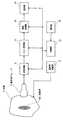
以下、図面を参照して発明を実施するための最良の形態を詳細に説明する。なお、本発明は、発明を実施するための最良の形態に限定されるものではない。図1に超音波診断装置のブロック(block)図を示す。本装置は発明を実施するための最良の形態の一例である。本装置の構成によって、超音波診断装置に関する本発明を実施するための最良の形態の一例が示される。 The best mode for carrying out the invention will be described below in detail with reference to the drawings. Note that the present invention is not limited to the best mode for carrying out the invention. FIG. 1 shows a block diagram of the ultrasonic diagnostic apparatus. This apparatus is an example of the best mode for carrying out the invention. An example of the best mode for carrying out the present invention relating to an ultrasonic diagnostic apparatus is shown by the configuration of the present apparatus.
図1に示すように、本装置は、超音波プローブ2を有する。超音波プローブ2は、図示しない複数の超音波トランスデューサ(transducer)のアレイ(array)を有する。個々の超音波トランスデューサは例えばPZT(チタン(Ti)酸ジルコン(Zr)酸鉛)セラミックス(ceramics)等の圧電材料によって構成される。 As shown in FIG. 1, the present apparatus has an
超音波プローブ2は、使用者により対象4に当接して使用される。対象4の関心領域には造影剤402が造影剤供給部8によって供給されている。造影剤402としては、微小な気泡を主体とするものが用いられる。造影剤402は静脈注射等により供給される。 The
超音波プローブ2は送受信部6に接続されている。送受信部6は、超音波プローブ2に駆動信号を与えて超音波を送波させる。送受信部6は、また、超音波プローブ2が受波したエコー信号を受信する。 The
送受信部6は、例えば図2に示すような走査を行う。すなわち、放射点200からz方向に延びる音線202で扇状の2次元領域206をθ方向に走査し、いわゆるセクタスキャン(sector scan)を行う。 The transmission /
送波および受波のアパーチャを超音波トランスデューサアレイの一部を用いて形成するときは、このアパーチャをアレイに沿って順次移動させることにより、例えば図3に示すような走査を行うことができる。すなわち、放射点200からz方向に発する音線202を直線状の軌跡204に沿って平行移動させることにより、矩形状の2次元領域206をx方向に走査し、いわゆるリニアスキャン(linear scan)を行う。 When the transmission and reception apertures are formed by using a part of the ultrasonic transducer array, the apertures are sequentially moved along the array to perform scanning as shown in FIG. 3, for example. That is, by moving a sound ray 202 emitted from the radiation point 200 in the z direction along a linear locus 204, a rectangular two-dimensional region 206 is scanned in the x direction, and a so-called linear scan is performed. Do.
なお、超音波トランスデューサアレイが、超音波送波方向に張り出した円弧に沿って形成されたいわゆるコンベックスアレイ(convex array)である場合は、リニアスキャンと同様な音線走査により、例えば図4に示すように、音線202の放射点200を円弧状の軌跡204に沿って移動させ、扇面状の2次元領域206をθ方向に走査して、いわゆるコンベックススキャンが行える。 When the ultrasonic transducer array is a so-called convex array formed along an arc extending in the ultrasonic wave transmission direction, for example, as shown in FIG. As described above, the so-called convex scan can be performed by moving the radiation point 200 of the sound ray 202 along the arc-shaped locus 204 and scanning the fan-shaped two-dimensional region 206 in the θ direction.
送受信部6はエコー処理部10に接続されている。送受信部6から出力される音線ごとのエコー受信信号はエコー処理部10に入力される。エコー処理部10はエコー信号を処理して画像データを形成する。 The transmission /
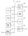
エコー処理部10は画像処理部14に接続されている。画像処理部14は、エコー処理部10から入力されるデータに基づいて画像を生成する。画像処理部14は、図5に示すように、セントラル・プロセシング・ユニット(CPU: Centeral Processing Unit)140を有する。CPU140には、バス(bus)142によって、メインメモリ(main memory)144、外部メモリ146、制御部インターフェース(interface)148、入力データメモリ(data memory)152、ディジタル・スキャンコンバータ(DSC: Digital Scan Converter)154、画像メモリ156、および、ディスプレーメモリ(display memory)158が接続されている。 The
外部メモリ146には、CPU140が実行するプログラムが記憶されている。外部メモリ146には、また、CPU140がプログラムを実行するに当たって使用する種々のデータも記憶されている。 The
CPU140は、外部メモリ146からプログラムをメインメモリ144にロード(load)して実行することにより、所定のデータ処理を遂行する。データ処理にはTICの測定が含まれる。CPU140は、プログラム実行の過程で、制御部インターフェース148を通じて後述の制御部18と制御信号の授受を行う。 The
エコー処理部10から音線ごとに入力された画像データは、入力データメモリ152にそれぞれ記憶される。入力データメモリ152のデータは、DSC154で走査変換されて画像メモリ156に記憶される。画像メモリ156のデータはディスプレーメモリ158を通じて表示部16に出力される。 The image data input for each sound ray from the
画像処理部14には表示部16が接続されている。表示部16は、画像処理部14から画像信号が与えられ、それに基づいて画像を表示するようになっている。表示部16は、カラー(color)画像が表示可能なCRT(cathode−ray tube)を用いたグラフィックディスプレー(graphic display)等で構成される。 A
以上の送受信部6、エコー処理部10、画像処理部14および表示部16には制御部18が接続されている。制御部18は、それら各部に制御信号を与えてその動作を制御する。制御部18には、被制御の各部から各種の報知信号が入力される。制御部18の制御の下で造影撮影が実行される。 A
制御部18には操作部20が接続されている。操作部20は使用者によって操作され、制御部18に適宜の指令や情報を入力するようになっている。操作部20は、例えばキーボード(keyboard)やポインティングデバイス(pointing device)およびその他の操作具を備えている。 An
本装置の動作を説明する。図6は、本装置の動作のフロー(flow)図である。同図に示すように、ステージ601で、造影撮影を行う。すなわち、造影剤供給部8により対象4に造影剤が注入され、造影剤が体内に注入されたタイミングが操作部16を通じて入力され、経過時間の計測が開始され、例えば肝臓等についての造影撮影が行われる。これによって肝臓の断層像が表示部16に表示される。 The operation of this apparatus will be described. FIG. 6 is a flowchart of the operation of the present apparatus. As shown in the figure, contrast imaging is performed at
次に、ステージ603で、ROI設定を行う。ROI設定は使用者の操作に基づいて画像処理部14によって行われる。使用者は操作部20に備わるポインティングデバイス等の操作具で断層像上にROIを設定する。操作部20および画像処理部14は、本発明における設定手段の一例である。 Next, ROI setting is performed at
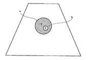
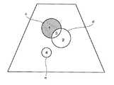
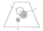
これによって、例えば図7に示すようなROIaおよびROIbが設定される。ここでは円形のROIを示すが、ROIの形状は患部の形状に応じて適宜に設定してよい。ROIbはROIaの中に設定されている。ROIaが例えば肝癌の範囲であるとするとROIbは例えば結節の範囲である。 Thereby, for example, ROIa and ROIb as shown in FIG. 7 are set. Although a circular ROI is shown here, the shape of the ROI may be appropriately set according to the shape of the affected part. ROIb is set in ROIa. If ROIa is in the range of liver cancer, for example, ROIb is in the range of nodule, for example.
このようなROI設定により、ROIを規定する境界線によって囲まれた2つの区画1,2ができる。区画1はROIaからROIbを除いたものに相当する。区画2はROIaとROIbの重複部分であり、また、ROIbそのものでもある。 By such ROI setting, two
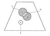
次に、ステージ605で、区画指定を行う。区画指定は使用者の操作に基づいて画像処理部14によって行われる。操作部20および画像処理部14は、本発明における指定手段の一例である。これによって、図8に斜線で示すように、例えば区画1と区画2の組合せがTIC測定範囲として指定される。この組合せはROIaとROIbの論理和に相当し、また、ROIaそのものでもある。 Next, on
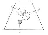
区画1を指定したときは、図9に示すように、ROIaからROIbを除いたものが指定される。これはROIaとROIbの排他的論理和に相当する。区画2を指定したときは、図10に示すように、ROIbのみについての指定となる。これはまたROIaとROIbの論理積に相当する。 When
次に、ステージ607で、TIC測定を行う。TIC測定は画像処理部14のCPU140によって行われる。画像処理部14は、本発明における測定手段の一例である。CPU140は、画像メモリ156に記憶された画像について、指定された区画の画素値の平均値を求め、その経時的変化すなわちTICを表示部16にグラフ(graph)で表示する。 Next, at
図8に示したような区画指定のときは、結節部を含んだROIa全体のTICが示されるが、図9に示したような区画指定のときは、肝癌から結節を除いた部分のTICを得ることができる。また、図10に示したような区画指定のときは、結節のみについてのTICを得ることができる。 When the section designation as shown in FIG. 8 is performed, the TIC of the entire ROIa including the nodule portion is shown, but when the section designation as shown in FIG. 9 is performed, the TIC of the portion excluding the nodule from the liver cancer is displayed. Obtainable. In addition, when a section is designated as shown in FIG. 10, a TIC for only a nodule can be obtained.
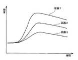
さらには、指定に応じて区画1と区画2のTICを別々に求めることが可能であり、これによって、例えば図11に示すように、それぞれの区画についてのTICを得ることができる。このようにすることにより、2つのTICの対比から診断上有力な情報を得ることができる。 Furthermore, it is possible to separately obtain the TICs of the
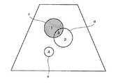
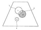
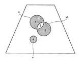
図12に、ROI設定の他の例を示す。同図に示すように、3つのROIc,d,eが設定される。ROIcとROIdは部分的に重複し、ROIeはどれとも重複しないものである。 FIG. 12 shows another example of ROI setting. As shown in the figure, three ROIc, d, and e are set. ROIc and ROId partially overlap, and ROIe does not overlap any of them.
ここでは、ROIを規定する境界線によって囲まれた4つの区画1,2,3,4ができる。区画1はROIcからROIdとの重複部分を除いたものとなる。区画2はROIdからROIcとの重複部分を除いたものとなる。区画3はROIcとROIdの重複部分となる。区画4はROIeそのものである。 Here, four
このような場合における区画指定の例を図13−27に示す。図13は区画1,3を指定した例である。これはROIcの指定に他ならない。図14は区画2,3を指定した例である。これはROIdの指定に他ならない。図15は区画1を指定した例である。これはROIcからROIdとの重複部分を除いたものに相当する。図16は区画2を指定した例である。これはROIdからROIcとの重複部分を除いたものに相当する。図17は区画1,2,3を指定した例である。これはROIdとROIcの論理和に相当する。図18は区画1,2を指定した例である。これはROIdとROIcの排他的論理和に相当する。 An example of partition designation in such a case is shown in FIGS. FIG. 13 shows an example in which
図19は区画4を指定した例である。これはROIeのみを指定したものである。図20は区画1,3,4を指定した例である。これはROIcとROIeを指定したものに相当する。図21は区画2,3,4を指定した例である。これはROIdとROIeを指定したものに相当する。 FIG. 19 shows an example in which the
図22は区画1,4を指定した例である。これはROIcからROIdとの重複部分を除いたものとROIeを指定したものである。図23は区画2,4を指定した例である。これはROIdからROIcとの重複部分を除いたものとROIeを指定したものである。図24は区画1,2,3,4を指定した例である。これはROIdとROIcの論理和とROIeを指定したものである。図25は区画1,2,4を指定した例である。これはROIdとROIcの排他的論理和とROIeを指定したものである。 FIG. 22 shows an example in which
図26は区画3を指定した例である。これはROIcとROIdの論理積に相当する。図27は区画3,4を指定した例である。これはROIcとROIdの論理積とROIeを指定したものである。 FIG. 26 shows an example in which the
このような区画指定によって、それぞれ、ROIにおける所望の部分についてのTICを得ることができる。したがって、それらTICに基づいて的確な診断を行うことが可能になる。 By such partition designation, a TIC for a desired portion in the ROI can be obtained. Therefore, accurate diagnosis can be performed based on these TICs.
図28に、本装置の他の動作のフロー図を示す。同図において図6に示したステージと同様なステージは同一の符号を付して説明を省略する。この動作では、ステージ605’で区画指定の代わりにROI分割を行う。ROI分割は予め用意されたパターン(pattern)の中から使用者によって指定されたものに従って行われる。ROI分割は使用者の操作に基づいて画像処理部14によって行われる。操作部20および画像処理部14は、本発明における分割手段の一例である。 FIG. 28 shows a flowchart of another operation of the present apparatus. In the figure, the same stage as the stage shown in FIG. In this operation, ROI division is performed at stage 605 'instead of partition designation. The ROI division is performed according to a pattern designated by the user from among patterns prepared in advance. The ROI division is performed by the
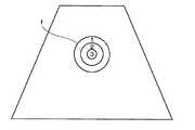
ROI分割の例を図29−31に示す。図29はROIfを同心円状に分割した例である。これによって例えば区画1,2,3が形成される。このようにして、順次内包の関係にある複数の区画を得ることができる。なお、同心円に限らず、楕円や多角形をした相似形であってよい。また、中心が共通である必要はない。 An example of ROI division is shown in FIGS. 29-31. FIG. 29 shows an example of dividing ROIf into concentric circles. Thereby, for example,
図30はROIfを中心を通る直線で分割した例である。これによって例えば区画1,2,3,4が形成される。このようにして複数の区画の対称性を得ることができる。図31はROIfを平行な複数の直線で分割した例である。これによって例えば区画1,2,3,4が形成される。このようにして複数の区画の平行性を得ることができる。なお、分割のパターンは図示のものに限らず適宜でよい。 FIG. 30 shows an example in which ROIf is divided by a straight line passing through the center. Thereby, for example,
このようなROI分割によって生成された区画のおのおのについて、ステージ607でTICが求められる。これによって、例えば図32に示すように、各区画ごとにTICを表示することができる。したがって、このようなTICに基づいて的確な診断を行うことが可能になる。 A TIC is obtained at
2 超音波プローブ
4 対象
402 造影剤
6 送受信部
8 造影剤供給部
10 エコー処理部
14 画像処理部
16 表示部
18 制御部
20 操作部2
Claims (6)
Translated fromJapanese一部の領域が重なるように複数のROIを設定する設定手段と、
前記ROIを規定する境界線によって囲まれた区画を個々に指定可能な指定手段と、
前記指定された区画についてTICを求める測定手段と、
を具備することを特徴とする超音波診断装置。An ultrasound diagnostic apparatus that takes a contrast image using ultrasound and obtains a TIC for an ROI,
Setting means for setting a plurality of ROIsso that some areas overlap ;
Designation meanscapable of individually designating a section surrounded by a boundary line defining the ROI;
Measuring means for obtaining a TIC for the designated section;
An ultrasonic diagnostic apparatus comprising:
ことを特徴とする請求項1に記載の超音波診断装置。The designated partition is a logical product of a plurality of ROIs;
The ultrasonic diagnostic apparatus according to claim 1.
ことを特徴とする請求項1に記載の超音波診断装置。The designated partition is a logical OR of a plurality of ROIs;
The ultrasonic diagnostic apparatus according to claim 1.
ことを特徴とする請求項1に記載の超音波診断装置。The designated partition is an exclusive OR of a plurality of ROIs;
The ultrasonic diagnostic apparatus according to claim 1.
重複可能な複数のROIを設定する設定手段と、
前記ROIを規定する境界線によって囲まれた区画において複数のROIの論理和である区画を指定する指定手段と、
前記指定された区画についてTICを求める測定手段と、
を具備することを特徴とする超音波診断装置。An ultrasound diagnostic apparatus that takes a contrast image using ultrasound and obtains a TIC for an ROI,
Setting means for settinga plurality of overlapping ROIs;
Designating means for designating a section that is a logical sum of a plurality of ROIs in a section surrounded by a boundary line thatdefines the ROI;
Measuring means for obtaining a TIC for thedesignated section ;
An ultrasonic diagnostic apparatus comprising:
小ROIの全領域が大ROIに含まれるように複数のROIを設定する設定手段と、
前記小ROIの全領域を含んだ前記大ROIの領域を指定する指定手段と、
前記指定された領域についてTICを求める測定手段と、
を具備することを特徴とする超音波診断装置。An ultrasound diagnostic apparatus that takes a contrast image using ultrasound and obtains a TIC for an ROI,
Setting means for setting a plurality of ROIs so that the entire region of the small ROI is included in the large ROI;
Designating means for designating the area of the large ROI including the entire area of the small ROI;
Measuring means for obtaining a TIC for the specified area;
Ultrasonic diagnostic apparatus characterizedby comprising a.
Priority Applications (1)
| Application Number | Priority Date | Filing Date | Title |
|---|---|---|---|
| JP2003333264AJP4494744B2 (en) | 2003-09-25 | 2003-09-25 | Ultrasonic diagnostic equipment |
Applications Claiming Priority (1)
| Application Number | Priority Date | Filing Date | Title |
|---|---|---|---|
| JP2003333264AJP4494744B2 (en) | 2003-09-25 | 2003-09-25 | Ultrasonic diagnostic equipment |
Related Child Applications (1)
| Application Number | Title | Priority Date | Filing Date |
|---|---|---|---|
| JP2009286110ADivisionJP2010088927A (en) | 2009-12-17 | 2009-12-17 | Ultrasonic diagnostic equipment |
Publications (2)
| Publication Number | Publication Date |
|---|---|
| JP2005095376A JP2005095376A (en) | 2005-04-14 |
| JP4494744B2true JP4494744B2 (en) | 2010-06-30 |
Family
ID=34461311
Family Applications (1)
| Application Number | Title | Priority Date | Filing Date |
|---|---|---|---|
| JP2003333264AExpired - LifetimeJP4494744B2 (en) | 2003-09-25 | 2003-09-25 | Ultrasonic diagnostic equipment |
Country Status (1)
| Country | Link |
|---|---|
| JP (1) | JP4494744B2 (en) |
Families Citing this family (9)
| Publication number | Priority date | Publication date | Assignee | Title |
|---|---|---|---|---|
| WO2006126684A1 (en)* | 2005-05-27 | 2006-11-30 | Hitachi Medical Corporation | Ultrasonograph and ultrasonic image display method |
| US10130342B2 (en) | 2007-12-28 | 2018-11-20 | Bracco Suisse Sa | Initialization of fitting parameters for perfusion assessment based on bolus administration |
| JP2010075586A (en)* | 2008-09-29 | 2010-04-08 | Ge Medical Systems Global Technology Co Llc | Ultrasonic diagnostic apparatus |
| US8929634B2 (en) | 2009-09-01 | 2015-01-06 | Bracco Suisse Sa | Parametric images based on dynamic behavior over time |
| KR102123061B1 (en) | 2012-11-27 | 2020-06-16 | 삼성전자주식회사 | Boundary segmentation apparatus and method based on user interaction |
| JP6523326B2 (en) | 2014-04-07 | 2019-05-29 | ブラッコ・シュイス・ソシエテ・アノニムBracco Suisse SA | In-Situ Estimation of Sound Level by Non-fundamental Analysis |
| JP6803909B2 (en) | 2015-12-10 | 2020-12-23 | ブラッコ・シュイス・ソシエテ・アノニムBracco Suisse SA | Detection of immobilized contrast media with dynamic threshold |
| JP6490171B2 (en)* | 2017-10-11 | 2019-03-27 | キヤノン株式会社 | Data processing apparatus and data processing method |
| JP7732749B2 (en)* | 2020-11-05 | 2025-09-02 | キヤノンメディカルシステムズ株式会社 | Medical image processing device and medical image processing program |
Family Cites Families (1)
| Publication number | Priority date | Publication date | Assignee | Title |
|---|---|---|---|---|
| JP2001187052A (en)* | 2000-01-04 | 2001-07-10 | Ge Yokogawa Medical Systems Ltd | Method for setting control region and ultrasonic diagnostic equipment |
- 2003
- 2003-09-25JPJP2003333264Apatent/JP4494744B2/ennot_activeExpired - Lifetime
Also Published As
| Publication number | Publication date |
|---|---|
| JP2005095376A (en) | 2005-04-14 |
Similar Documents
| Publication | Publication Date | Title |
|---|---|---|
| JP4969985B2 (en) | Ultrasonic diagnostic apparatus and control program for ultrasonic diagnostic apparatus | |
| EP1745745B9 (en) | Apparatus for obtaining ultrasonic images and method of obtaining ultrasonic images | |
| JP4615105B2 (en) | Ultrasound imaging device | |
| US6669641B2 (en) | Method of and system for ultrasound imaging | |
| US11439368B2 (en) | Acoustic wave processing device, signal processing method for acoustic wave processing device, and program | |
| CN101547649B (en) | Ultrasonic diagnostic device | |
| US10117636B2 (en) | Ultrasonic diagnostic apparatus, ultrasonic image processing apparatus, medical image diagnostic apparatus, and medical image processing apparatus | |
| EP3547923B1 (en) | Ultrasound imaging system and method | |
| JP4494744B2 (en) | Ultrasonic diagnostic equipment | |
| US8303506B2 (en) | Ultrasonic diagnostic apparatus and ultrasonic imaging method and program | |
| KR20250035233A (en) | Ultrasound imaging apparatus and operating method for the same | |
| JP2002209900A (en) | Method and device for adjusting time gain, recording medium and ultrasonic imaging instrument | |
| JP5513755B2 (en) | Ultrasonic diagnostic apparatus and control program therefor | |
| JP2002119510A (en) | Ultrasonic photographing device | |
| JP7309498B2 (en) | Ultrasound diagnostic equipment and control program | |
| US7111515B2 (en) | Ultrasonic diagnostic apparatus and driving method therefor | |
| JP2022122023A (en) | ULTRASOUND DIAGNOSTIC APPARATUS, SETTING CONTROL METHOD AND SETTING CONTROL PROGRAM | |
| US7670293B2 (en) | Method and system for scan sequencing in an ultrasound imaging system | |
| JP2010088927A (en) | Ultrasonic diagnostic equipment | |
| JP4913332B2 (en) | Medical image display method and ultrasonic diagnostic apparatus | |
| JP3715745B2 (en) | Ultrasonic imaging device | |
| JP2000300560A (en) | Ultrasound diagnostic equipment | |
| JP2000201930A (en) | 3D ultrasonic diagnostic equipment | |
| JP2002165795A (en) | Method and device for setting region of interest, and ultrasonic imaging device | |
| JP2023517512A (en) | Contextual multiplanar reconstruction of 3D ultrasound image data and related apparatus, systems, and methods |
Legal Events
| Date | Code | Title | Description |
|---|---|---|---|
| A625 | Written request for application examination (by other person) | Free format text:JAPANESE INTERMEDIATE CODE: A625 Effective date:20060905 | |
| A977 | Report on retrieval | Free format text:JAPANESE INTERMEDIATE CODE: A971007 Effective date:20090930 | |
| A131 | Notification of reasons for refusal | Free format text:JAPANESE INTERMEDIATE CODE: A131 Effective date:20091006 | |
| A521 | Request for written amendment filed | Free format text:JAPANESE INTERMEDIATE CODE: A523 Effective date:20091217 | |
| TRDD | Decision of grant or rejection written | ||
| A01 | Written decision to grant a patent or to grant a registration (utility model) | Free format text:JAPANESE INTERMEDIATE CODE: A01 Effective date:20100330 | |
| A01 | Written decision to grant a patent or to grant a registration (utility model) | Free format text:JAPANESE INTERMEDIATE CODE: A01 | |
| A61 | First payment of annual fees (during grant procedure) | Free format text:JAPANESE INTERMEDIATE CODE: A61 Effective date:20100408 | |
| R150 | Certificate of patent or registration of utility model | Ref document number:4494744 Country of ref document:JP Free format text:JAPANESE INTERMEDIATE CODE: R150 Free format text:JAPANESE INTERMEDIATE CODE: R150 | |
| FPAY | Renewal fee payment (event date is renewal date of database) | Free format text:PAYMENT UNTIL: 20130416 Year of fee payment:3 | |
| FPAY | Renewal fee payment (event date is renewal date of database) | Free format text:PAYMENT UNTIL: 20130416 Year of fee payment:3 | |
| FPAY | Renewal fee payment (event date is renewal date of database) | Free format text:PAYMENT UNTIL: 20140416 Year of fee payment:4 | |
| R250 | Receipt of annual fees | Free format text:JAPANESE INTERMEDIATE CODE: R250 | |
| R250 | Receipt of annual fees | Free format text:JAPANESE INTERMEDIATE CODE: R250 | |
| R250 | Receipt of annual fees | Free format text:JAPANESE INTERMEDIATE CODE: R250 | |
| R250 | Receipt of annual fees | Free format text:JAPANESE INTERMEDIATE CODE: R250 | |
| R250 | Receipt of annual fees | Free format text:JAPANESE INTERMEDIATE CODE: R250 | |
| R250 | Receipt of annual fees | Free format text:JAPANESE INTERMEDIATE CODE: R250 | |
| R250 | Receipt of annual fees | Free format text:JAPANESE INTERMEDIATE CODE: R250 | |
| R250 | Receipt of annual fees | Free format text:JAPANESE INTERMEDIATE CODE: R250 | |
| R250 | Receipt of annual fees | Free format text:JAPANESE INTERMEDIATE CODE: R250 | |
| R250 | Receipt of annual fees | Free format text:JAPANESE INTERMEDIATE CODE: R250 | |
| R250 | Receipt of annual fees | Free format text:JAPANESE INTERMEDIATE CODE: R250 | |
| EXPY | Cancellation because of completion of term |