JP4493893B2 - Multifunctional curved blade for use with ultrasonic surgical instruments - Google Patents
Multifunctional curved blade for use with ultrasonic surgical instrumentsDownload PDFInfo
- Publication number
- JP4493893B2 JP4493893B2JP2001527715AJP2001527715AJP4493893B2JP 4493893 B2JP4493893 B2JP 4493893B2JP 2001527715 AJP2001527715 AJP 2001527715AJP 2001527715 AJP2001527715 AJP 2001527715AJP 4493893 B2JP4493893 B2JP 4493893B2
- Authority
- JP
- Japan
- Prior art keywords
- ultrasonic
- surface portion
- clamp
- edge portion
- clamp arm
- Prior art date
- Legal status (The legal status is an assumption and is not a legal conclusion. Google has not performed a legal analysis and makes no representation as to the accuracy of the status listed.)
- Expired - Lifetime
Links
- 239000012636effectorSubstances0.000claimsdescription55
- 238000007711solidificationMethods0.000claimsdescription30
- 230000008023solidificationEffects0.000claimsdescription30
- 230000015271coagulationEffects0.000claimsdescription26
- 238000005345coagulationMethods0.000claimsdescription26
- 230000033001locomotionEffects0.000claimsdescription18
- 230000007246mechanismEffects0.000claimsdescription17
- 238000005520cutting processMethods0.000claimsdescription13
- 239000000463materialSubstances0.000description25
- 238000013016dampingMethods0.000description22
- 210000000078clawAnatomy0.000description8
- 238000000034methodMethods0.000description8
- 238000002604ultrasonographyMethods0.000description8
- 230000009471actionEffects0.000description7
- 239000007787solidSubstances0.000description6
- 230000006872improvementEffects0.000description4
- 230000026683transductionEffects0.000description4
- 238000010361transductionMethods0.000description4
- 239000004697PolyetherimideSubstances0.000description3
- 239000000853adhesiveSubstances0.000description3
- 230000001070adhesive effectEffects0.000description3
- 230000005540biological transmissionEffects0.000description3
- 238000006073displacement reactionMethods0.000description3
- 229920001601polyetherimidePolymers0.000description3
- 229920001343polytetrafluoroethylenePolymers0.000description3
- 239000004810polytetrafluoroethyleneSubstances0.000description3
- 239000000243solutionSubstances0.000description3
- 239000010935stainless steelSubstances0.000description3
- 229910001220stainless steelInorganic materials0.000description3
- 230000000638stimulationEffects0.000description3
- 238000001356surgical procedureMethods0.000description3
- 210000003813thumbAnatomy0.000description3
- 229910000838Al alloyInorganic materials0.000description2
- 239000004677NylonSubstances0.000description2
- QQONPFPTGQHPMA-UHFFFAOYSA-NPropeneChemical compoundCC=CQQONPFPTGQHPMA-UHFFFAOYSA-N0.000description2
- 229920006362Teflon®Polymers0.000description2
- 229910001069Ti alloyInorganic materials0.000description2
- 229910000883Ti6Al4VInorganic materials0.000description2
- 238000013459approachMethods0.000description2
- 238000013461designMethods0.000description2
- 230000006870functionEffects0.000description2
- 230000023597hemostasisEffects0.000description2
- 238000001746injection mouldingMethods0.000description2
- 238000004519manufacturing processMethods0.000description2
- 229910052751metalInorganic materials0.000description2
- 239000002184metalSubstances0.000description2
- 229920001778nylonPolymers0.000description2
- 230000002093peripheral effectEffects0.000description2
- 239000004033plasticSubstances0.000description2
- 229920003023plasticPolymers0.000description2
- 239000004417polycarbonateSubstances0.000description2
- 229920000515polycarbonatePolymers0.000description2
- 229920001296polysiloxanePolymers0.000description2
- 238000003825pressingMethods0.000description2
- 238000003466weldingMethods0.000description2
- 229920001651CyanoacrylatePolymers0.000description1
- 239000005977EthyleneSubstances0.000description1
- MWCLLHOVUTZFKS-UHFFFAOYSA-NMethyl cyanoacrylateChemical compoundCOC(=O)C(=C)C#NMWCLLHOVUTZFKS-UHFFFAOYSA-N0.000description1
- 229920000122acrylonitrile butadiene styrenePolymers0.000description1
- 239000004676acrylonitrile butadiene styreneSubstances0.000description1
- 238000005452bendingMethods0.000description1
- 230000008901benefitEffects0.000description1
- 239000008280bloodSubstances0.000description1
- 210000004369bloodAnatomy0.000description1
- 210000004204blood vesselAnatomy0.000description1
- 230000008859changeEffects0.000description1
- 238000006243chemical reactionMethods0.000description1
- 230000001112coagulating effectEffects0.000description1
- 239000003086colorantSubstances0.000description1
- 238000004891communicationMethods0.000description1
- 239000013078crystalSubstances0.000description1
- NKZSPGSOXYXWQA-UHFFFAOYSA-Ndioxido(oxo)titanium;lead(2+)Chemical compound[Pb+2].[O-][Ti]([O-])=ONKZSPGSOXYXWQA-UHFFFAOYSA-N0.000description1
- 238000001125extrusionMethods0.000description1
- 210000003811fingerAnatomy0.000description1
- 238000002347injectionMethods0.000description1
- 239000007924injectionSubstances0.000description1
- 238000003780insertionMethods0.000description1
- 230000037431insertionEffects0.000description1
- 238000005304joiningMethods0.000description1
- 238000002357laparoscopic surgeryMethods0.000description1
- 238000003754machiningMethods0.000description1
- 238000002324minimally invasive surgeryMethods0.000description1
- 238000012986modificationMethods0.000description1
- 230000004048modificationEffects0.000description1
- 238000000465mouldingMethods0.000description1
- 230000000149penetrating effectEffects0.000description1
- 230000035515penetrationEffects0.000description1
- 229920000642polymerPolymers0.000description1
- 239000002861polymer materialSubstances0.000description1
- -1polytetrafluoroethylenePolymers0.000description1
- 230000036316preloadEffects0.000description1
- 230000008569processEffects0.000description1
- 230000005855radiationEffects0.000description1
- 230000004044responseEffects0.000description1
- 230000000087stabilizing effectEffects0.000description1
- 230000001954sterilising effectEffects0.000description1
- 238000004659sterilization and disinfectionMethods0.000description1
- 238000006467substitution reactionMethods0.000description1
- 238000004381surface treatmentMethods0.000description1
- 238000010408sweepingMethods0.000description1
- 230000002463transducing effectEffects0.000description1
- 230000002792vascularEffects0.000description1
Images


Classifications
- A—HUMAN NECESSITIES
- A61—MEDICAL OR VETERINARY SCIENCE; HYGIENE
- A61B—DIAGNOSIS; SURGERY; IDENTIFICATION
- A61B17/00—Surgical instruments, devices or methods
- A61B17/32—Surgical cutting instruments
- A61B17/320068—Surgical cutting instruments using mechanical vibrations, e.g. ultrasonic
- A61B17/320092—Surgical cutting instruments using mechanical vibrations, e.g. ultrasonic with additional movable means for clamping or cutting tissue, e.g. with a pivoting jaw
- A61B2017/320093—Surgical cutting instruments using mechanical vibrations, e.g. ultrasonic with additional movable means for clamping or cutting tissue, e.g. with a pivoting jaw additional movable means performing cutting operation
- A—HUMAN NECESSITIES
- A61—MEDICAL OR VETERINARY SCIENCE; HYGIENE
- A61B—DIAGNOSIS; SURGERY; IDENTIFICATION
- A61B17/00—Surgical instruments, devices or methods
- A61B17/32—Surgical cutting instruments
- A61B17/320068—Surgical cutting instruments using mechanical vibrations, e.g. ultrasonic
- A61B17/320092—Surgical cutting instruments using mechanical vibrations, e.g. ultrasonic with additional movable means for clamping or cutting tissue, e.g. with a pivoting jaw
- A61B2017/320094—Surgical cutting instruments using mechanical vibrations, e.g. ultrasonic with additional movable means for clamping or cutting tissue, e.g. with a pivoting jaw additional movable means performing clamping operation
- A—HUMAN NECESSITIES
- A61—MEDICAL OR VETERINARY SCIENCE; HYGIENE
- A61B—DIAGNOSIS; SURGERY; IDENTIFICATION
- A61B17/00—Surgical instruments, devices or methods
- A61B17/32—Surgical cutting instruments
- A61B17/320068—Surgical cutting instruments using mechanical vibrations, e.g. ultrasonic
- A61B17/320092—Surgical cutting instruments using mechanical vibrations, e.g. ultrasonic with additional movable means for clamping or cutting tissue, e.g. with a pivoting jaw
- A61B2017/320095—Surgical cutting instruments using mechanical vibrations, e.g. ultrasonic with additional movable means for clamping or cutting tissue, e.g. with a pivoting jaw with sealing or cauterizing means
Landscapes
- Health & Medical Sciences (AREA)
- Surgery (AREA)
- Engineering & Computer Science (AREA)
- Life Sciences & Earth Sciences (AREA)
- Heart & Thoracic Surgery (AREA)
- Nuclear Medicine, Radiotherapy & Molecular Imaging (AREA)
- Mechanical Engineering (AREA)
- Biomedical Technology (AREA)
- Dentistry (AREA)
- Medical Informatics (AREA)
- Molecular Biology (AREA)
- Animal Behavior & Ethology (AREA)
- General Health & Medical Sciences (AREA)
- Public Health (AREA)
- Veterinary Medicine (AREA)
- Surgical Instruments (AREA)
- Ultra Sonic Daignosis Equipment (AREA)
Description
Translated fromJapanese【0001】
発明の分野
本発明は、一般に、超音波外科用のクランプ器具に関し、特に、超音波外科用のクランプ器具のための多機能な湾曲状シャー・ブレードに関する。
【0002】
発明の背景
この特許出願は以下の同時係属の特許出願、すなわち、1997年10月10日に出願されている米国特許出願第08/948,625号、1997年10月10日に出願されている同第08/949,133号、1998年6月29日に出願されている同第09/106,686号、1999年6月21日に出願されている同第09/337,077号、同第09/412,557号、同第09/412,996号、および同第09/412,257号に関連しており、これらの文献は本明細書に参考文献として含まれる。
【0003】
中空コアおよび中実コアの各器具を含む超音波器具は多くの医療状態の安全で効果的な治療のために使用されている。超音波器具、特に中実コアの超音波器具はこれらが超音波周波数において外科エンド−エフェクターに伝達される機械的な振動の形態のエネルギーを用いて有機組織を切断および/または凝固するために使用できる点で有利である。超音波振動は、適当なエネルギー・レベルで有機組織に伝達されて適当なエンド−エフェクターを使用する場合に、組織を切断、切開、または焼灼するために使用できる。中実コア技法を利用している超音波器具はその超音波トランスデューサから導波管を介して外科エンド−エフェクターに伝達できる超音波エネルギーの量の理由により特に有利である。これらの器具は内視鏡または腹腔鏡による各処置を含む最少侵襲性の処置における使用に特に適しており、この場合のエンド−エフェクターはトロカールの中を通して外科部位に到達する。
【0004】
超音波振動は、例えば、器具のハンド・ピース内において1個以上の圧電変換素子または磁わい素子により構成できるトランスデューサを電気的に励起することにより外科エンド−エフェクターの中において誘発される。このトランスデューサ部分により発生される振動が当該トランスデューサ部分から外科エンド−エフェクターまで延在している超音波導波管を介して外科エンド−エフェクターに伝達される。
【0005】
中実コアの超音波外科器具は2種類の装置、すなわち、単一要素型のエンド−エフェクター装置および多数個要素型のエンド−エフェクターに分けることができる。単一要素のエンド−エフェクター装置は外科用メスおよびボール状凝固装置等の器具を含み、例えば、米国特許第5,263,957号を参照されたい。この米国特許第5,263,957号に開示されているような器具は相当に十分であることが知られているが、これらの用法ならびに別の超音波外科器具における用法において幾つかの制限がある。例えば、単一要素のエンド−エフェクター器具は組織が軟質であり緩やかに支持されている場合にブレードから組織に圧力を加える能力が制限されている。超音波エネルギーを組織に効果的に伝達するためには十分な圧力が必要である。このように組織を確実に捕らえることができなければ、超音波エネルギーの供給中に組織表面に対して完全に接着することができなくなり、不十分な止血および組織の結合の結果に到る。
【0006】
クランプ式凝固装置等の多数個要素型エンド−エフェクターの使用は超音波ブレードに対して組織を押し当てるための機構を含み、この機構により上記のような欠点が解消できる。超音波外科装置において有用であるとして開示されているクランプ機構がBalamuthに発行されている米国特許第3,636,943号および同第3,862,630号に記載されている。しかしながら、一般に、これらの特許に開示されているBalamuthの装置は十分な速度で凝固および切断せず、ブレードに対する接近がクランプにより遮られるのでクランプ無しの状態で切断/凝固のために使用できない点で融通性に欠けている。
【0007】
例えば、米国特許第5,322,055号および同第5,893,835号に開示されているような超音波クランプ式の凝固装置は組織、特に、緩やかに支持されているか全く支持されていない組織を切断/凝固するための改善された超音波外科器具を提供しており、この場合に、超音波ブレードは一定の圧縮力またはバイアス力を組織に加えるためのクランプと共に用いられており、これにより、比較的に速い組織の凝固および切断が行なえて、ブレード動作の減衰を比較的に少なくすることができる。
【0008】
既に本明細書に参考文献として含まれている米国特許出願第09/106,686号に記載されているような湾曲状の超音波器具の技法における改善は別の態様の湾曲状のクランプ式凝固装置における改善の必要性を示している。例えば、米国特許第5,873,873号は組織パッドを有するクランプ・アームを含むエンド−エフェクターを備えている超音波クランプ式凝固器具を記載している。この米国特許第5,873,873号に開示されている構成において、上記のクランプ・アームおよび組織パッドは直線状である。
【0009】
クランプ式凝固装置において使用されている超音波外科ブレードすなわちエンド−エフェクターの形状は器具における少なくとも4種類の重要な態様を定める。これらは(1)エンド−エフェクターの可視性およびその外科領域内における相対的な位置、(2)エンド−エフェクターの目的とされる組織への接近または進入の能力、(3)超音波エネルギーが切断および凝固のために組織に伝達される様式、および(4)組織が超音波的に不活性なエンド−エフェクターにより操作できる様式である。それゆえ、上記器具におけるこれら4種類の態様を最適化する改善された超音波クランプ式凝固装置を提供することが有利であると考えられる。
【0010】
Idemoto他はホーン本体部分および端部プレート部分を備えている外科手術において用いられる外科用超音波ホーンを開示している。切断部分が上記の端部部分のエッジ部および端部に備えられている。さらに、刺激溶液用の通路がホーン本体部分および端部プレート部分の中に延在している。少なくとも1個のボアが上記端部プレート部分の平面に対して5度乃至90度の噴射角度で上記切断部分において開口している。上記の刺激溶液通路はこのボアと連通しており、これにより、刺激溶液がその中を通して噴霧される。
【0011】
超音波出力を既存の装置よりも均一にクランプされている組織に対して供給することは有利であると考えられる。また、エンド−エフェクターの改善された可視性を提供してブレードが切断/凝固される構造部分を横切って延在していることを外科医が確認できることも有利であると考えられる。また、生物学的な各構造部分の湾曲部分にさらに似せているエンド−エフェクターによる改善された組織への接近を提供することも有利であると考えられる。また、多数の組織作用、すなわち、クランプ状態における凝固、クランプ状態における切断、把持、背部切断、切開、スポット凝固、末端部分の侵入およびスコア処理を提供するために設計されている多数のエッジ部分および表面部分を備えることも有利であると考えられる。また、僅かにフック状のまたは楔状の作用を利用して背部切断中にそれ自体で組織に張力を加えることができる超音波クランプ式凝固装置を提供することも有利であると考えられる。さらに、クランプ部材に対する相容性、切断用の鋭い特徴部分、接近性および可視性のための湾曲部分、および既存の装置よりもさらに均一な超音波出力の供給を含む特的な形状部分を使用している多機能的な超音波外科ブレードを提供することも有利であると考えられる。本発明はこれらの特徴および改善を以下に説明するように提供する。
【0012】
発明の概要
本発明はシャー型の構成の多数の機能を最良に実行するためのエンド−エフェクターの形状を組み合わせている超音波外科器具を開示する。このブレードの形状は湾曲状および潜在的にテーパー状の形状部分を形成するための丸みを付けた切断部分により特徴づけられている。この切断部分は、実施形態の一例において、凹状の表面部分および凸状の表面部分を含む湾曲状の表面部分を形成している。この凸状の表面部分は短い、直線状の、平坦な表面部分に変化している。この直線状の部分の長さは上記の湾曲状の形状により誘発される横方向の動作の音響学的な平衡化において、部分的に、作用する。直線状のブレード末端部分に比べて、本発明の設計による末端部分の湾曲形状は横断部位における改善された可視性および目的とされる組織への改善された接近性を提供する。実施形態の一例において、超音波ブレードが広いエッジ部分および狭いエッジ部分を有して説明されている。この広いエッジ部分は一定の垂直平面に沿って狭いエッジ部分の反対側に存在しており、狭いエッジ部分は第1の表面部分と第2の表面部分との交線により定められていて、この第1の表面部分は凹状である。
【0013】
発明の詳細な説明
以下、本発明を本明細書に記載するように超音波器具との組み合わせにおいて説明する。この説明は単に例示的であり、本発明の範囲および適用方法を制限することを目的としていない。例えば、本発明は、米国特許第5,938,633号、同第5,935,144号、同第5,944,737号、同第5,322,055号、同第5,630,420号、および同第5,449,370号において記載されている装置を含む多数の超音波器具との組み合わせにおいて有用である。
【0014】
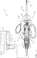
図1はサンドイッチ型の超音波トランスデューサ82、ハンド・ピース・ハウジング20、および本発明によるクランプ式凝固装置120と共に超音波信号発生器15を備えている超音波システム10を示している。このクランプ式凝固装置120は切開式または腹腔鏡式の手術において使用可能である。超音波トランスデューサ82は「ランジュバァン・スタック(Langevin stack)」として知られており、一般にトランスダクション部分90、第1の共振器またはエンド−ベル92、および第2の共振器またはフォア−ベル94、および補助部品を備えている。この超音波トランスデューサ82は後に詳述するようにシステム波長の1/2の整数倍の長さ(nλ/2)であることが好ましい。音響組立体80は上記の超音波トランスデューサ82、取付部材36、速度トランスフォーマ64および表面部分95を備えている。
【0015】
エンド−ベル92の先端部はトランスダクション部分90の基端部に接続しており、フォア−ベル94の基端部はトランスダクション部分90の先端部に接続している。フォア−ベル94およびエンド−ベル92はトランスダクション部分90の厚さ、エンド−ベル92およびフォア−ベル94を製造するために使用されている材料の密度および弾性率、および超音波トランスデューサ82の共振振動数を含む多数の変数により決定される一定の長さを有している。フォア−ベル94はその基端部からその先端部にかけて内側にテーパー状にして速度トランスフォーマ64として超音波振動の振幅を増幅可能にすることができ、あるいは、増幅作用を有していなくてもよい。
【0016】
圧電変換素子100は、例えば、ジルコン酸−チタン酸鉛、メタ−ニオブ酸鉛、チタン酸鉛、またはその他の圧電変換性の結晶材料を含む任意の適当な材料により製造できる。正電極96、負電極98、および圧電変換素子100はそれぞれその中心を貫通している中ぐり穴を有している。さらに、正電極96および負電極98はそれぞれ電線102および電線104に電気的に連結されている。各電線102および電線104はケーブル25の中に包まれていて、超音波システム10における超音波信号発生器15に電気的に接続可能である。
【0017】
音響組立体80の超音波トランスデューサ82は超音波信号発生器15からの電気的信号を機械的なエネルギーに変換し、このエネルギーが超音波トランスデューサ82およびエンド−エフェクター180の超音波周波数における主に長手方向の振動動作を生じる。この音響組立体80が励起すると、振動動作の定在波が当該音響組立体80の中に発生する。さらに、この音響組立体80に沿う任意点における振動動作の振幅はその振動動作を測定する音響組立体80に沿う場所により決まる。この振動動作の定在波における最小位置またはゼロ交叉位置は節部(node)(すなわち、動作が通常において最小である)として一般的に呼ばれており、この定在波における絶対値の最大位置またはピーク位置は一般に波腹部(anti-node)として呼ばれている。また、波腹部とそのこれに最も近い節部との間の距離は1/4波長(λ/4)である。
【0018】
各電線102および電線104は電気的な信号を超音波信号発生器15から正電極96および負電極98にそれぞれ伝達する。適当な発生器がオハイオ州シンシナティーのETHICON ENDO-SURGERY社からモデル番号GEN01として入手可能である。圧電変換素子100はフット・スイッチ118に応じて超音波信号発生器15から供給される電気的な信号により励起されて音響学的な定在波を音響組立体80の中に生じる。すなわち、この電気的な信号は各圧電変換素子100において繰り返し状態の小さな変位の形態で乱動を引き起こすことにより大きな圧縮力をこの材料の中に生じる。つまり、この繰り返し状態の小さな変位により各圧電変換素子100がその電圧勾配の軸に沿って連続的な様式で膨張および収縮することにより、超音波エネルギーの長手方向の波が生じる。この超音波エネルギーが音響組立体80を介してエンド−エフェクター180に伝達される。
【0019】
上記の音響組立体80がエンド−エフェクター180にエネルギーを供給するために、この音響組立体80における全ての部品が上記のクランプ式凝固装置120における超音波的に活性な各部分に音響学的に連結されている必要がある。例えば、超音波トランスデューサ82の先端部をスタッド50等のねじ付きの接続手段により超音波導波管179の基端部に表面部分95において音響学的に連結することが可能である。
【0020】
また、上記の音響組立体80における各部品はその任意の組立体の長さが1/2波長の整数倍(nλ/2)であるように音響学的に同調されていることが好ましく、この場合の波長λは所定の波長または音響組立体80の動作用の長手方向に沿う振動の駆動周波数fdであり、nは正の整数である。なお、上記の音響組立体80は各音響要素の任意の適当な配列構成を含むことが可能である。
【0021】
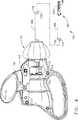
次に図2Aおよび図2Bにおいて、本発明による外科システム10におけるクランプ式凝固装置120が示されている。好ましくは、このクランプ式凝固装置120は1個のユニットとして上記の音響組立体80に対して着脱される。好ましくは、このクランプ式凝固装置120の基端部は図1に示されているように音響組立体80の先端側表面部分95に音響学的に連結されている。なお、このクランプ式凝固装置120が任意の適当な手段により音響組立体80に連結可能であることが認識されると考える。
【0022】
好ましくは、上記のクランプ凝固装置120は器具ハウジング130、および細長い部材150を備えている。この細長い部材150は以下に詳述するように器具ハウジング130に対して選択的に回転できる。器具ハウジング130は旋回式のハンドル部分136、および左側シュラウド134および右側シュラウド138にそれぞれ連結されている固定式のハンドル132Aおよびハンドル132Bを備えている。
【0023】
右側シュラウド138は左側シュラウド134においてスナップ嵌めすることに適合している。好ましくは、この右側シュラウド138は当該右側シュラウド138に形成されている内側に対向している複数のプロング70により左側シュラウド134に連結されている。これら複数のプロング70は左側シュラウド134の中に形成されている対応する各穴または孔140の中に係合するように配列されている。左側シュラウド134を右側シュラウド138に取り付ける際に、これらの間に、後に詳述するような指定機構255等の種々の部品に適合する一定のキャビティが形成される。
【0024】
上記のクランプ式凝固装置120における左側シュラウド134および右側シュラウド138はポリカーボネートにより製造されることが好ましい。なお、これらの構成部品は本発明の趣旨および範囲から逸脱することなく任意の適当な材料により作成することが可能であると考えられる。
【0025】
指定機構255は上記の器具ハウジング130におけるキャビティの中に配置されている。好ましくは、この指定機構255は内側チューブ170に連結または取り付けられていて、ハンドル部分136の移動を内側チューブ170の線形動作に変換してクランプ・アーム組立体300を開閉する。すなわち、旋回式のハンドル部分136が固定式のハンドル部分130の方向に移動すると、指定機構255が内側チューブ170を後方に摺動させてクランプ・アーム組立体300を閉じた状態に旋回させる。また、旋回式のハンドル部分136が上記と反対の方向に移動すると、指定機構255が内側チューブ170を上記と反対の方向、すなわち、前方に移動するように摺動して、クランプ・アーム組立体300をその開口した状態に旋回させる。
【0026】
上記の指定機構255は細長い部材150を器具ハウジング130に対してその長手軸の回りに回転可能にするためのラチェット機構も備えている。この細長い部材150の回転により、クランプ・アーム300が選択された所望の角度位置まで回転可能になる。上記の指定機構255は好ましくは管状カラー260およびヨーク280を備えている。
【0027】
上記の指定機構255の管状カラー260は好ましくは内側チューブ170の基端部上にスナップ嵌めされていて、反対側の開口部168の中にキー係合している。この管状カラー260は好ましくはポリエーテルイミドにより製造されている。なお、この管状カラー260は任意の適当な材料により構成することができる。
【0028】
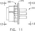
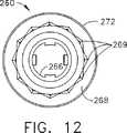
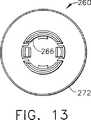
上記の管状カラー260は図11乃至図13にさらに詳細に示されている。好ましくは、この管状カラー260は拡大部分262、およびその中に貫通しているボア(中ぐり穴)266を有している。この拡大部分262は好ましくは管状カラー260の周縁部の周囲に形成されていて溝部268を形成しているリング272を備えている。この溝部268は複数のデテントまたは歯部269を有しており、これらの歯部269は上記の細長い部材150がその長手軸の回りに回転する時に当該細長い部材150を異なる回転位置に保持するために作用する。好ましくは、溝部268は12個のラチェット歯部を有していて、約30度の12個の等角度の増加分で上記の細長い部分を回転可能にしている。なお、上記の管状カラー260は任意数の歯状の部材を有することができる。また、これらの歯状の部材が本発明の範囲および趣旨から逸脱することなく管状カラー260の任意の適当な部分に配置可能であることが認識されると考える。
【0029】
次に図2A乃至図4に戻り、上記旋回式のハンドル部分136は親指用のループ142、第1の穴124、および第2の穴126を有している。ピボット・ピン153がハンドル部分136の第1の穴124の中に配置されていて、図3において矢印121により示されているような旋回を可能にしている。旋回式のハンドル部分136の親指用のループ142が器具ハウジング130から離間して矢印121の方向に移動すると、リンク128が前方方向の一定の力をヨーク280に加えることにより、ヨーク280が前方に移動する。リンク128はピン129により旋回式のハンドル部分136に接続されており、さらに、このリンク128はピン127により基部284に接続されている。
【0030】
次に図2Aに戻り、ヨーク280は一般に保持または支持部材282および基部284を有している。この支持部材282は好ましくは半円形であり、上記管状カラー260の歯部269に対して係合するために内側に延出している一対の対向している爪286を有している。なお、これらの爪286は本発明の趣旨および範囲から逸脱することなく管状カラー260の歯部269に対する係合のためにヨーク280の任意の適当な部分に配置可能であると考えられる。また、このヨーク280が任意数のラチェット・アームを有し得ることも認識されると考える。
【0031】
上記のヨーク280は図19乃至図22にさらに詳細に示されている。旋回式のハンドル部分136は好ましくはヨーク280の基部284におけるスロット147の中に部分的に配置されている。この基部284は基部開口部287、アクチュエータ移動停止部290、および基部ピン−ホール288を有している。上記のピボット・ピン153は基部開口部287の中を通して配置されている。ヨーク280における各爪286は管状カラー260を介して内側チューブ170に開口力を伝達し、これにより、クランプ・アーム組立体300が開口する。
【0032】
上記のクランプ式凝固装置120におけるヨーク280は好ましくはポリカーボネートにより製造されている。また、このヨーク280はABS、ナイロン、またはポリエーテルイミド等の別のプラスチック材料を含む種々の材料により作成することも可能である。さらに、このヨーク280は本発明の趣旨および範囲から逸脱することなく任意の適当な材料により構成可能であると考えられる。
【0033】
図3および図4に示されているように、ヨーク280は旋回式のハンドル部分136が器具ハウジング130の方向に移動する時にクランプ・アーム組立体300に一定の閉鎖力を伝達する。アクチュエータ移動停止部290は旋回式のハンドル部分136のストロークの底部においてピボット・ピン153に接触することにより、この旋回式のハンドル部分136のさらなる移動、すなわち過剰移動を阻止する。ヨーク280の各爪286はワッシャー151、力制限スプリング155、およびカラー・キャップ152を介して管状カラー260に力を伝達する。カラー・キャップ152はワッシャー151および力制限スプリング155が拡大部分262よりも基端側の管状カラー260上に組立てられた後に管状カラー260に強固に取り付けられる。このカラー・キャップ152は図5および図6にさらに詳細に示されている。また、力制限スプリング155は図7および図8にさらに詳細に示されており、ワッシャー151は図9および図10にさらに詳細に示されている。ワッシャー151の厚さはクランプ式凝固装置120の設計または製造中に調節されて、力制限スプリング155の予荷重を変更することができる。カラー・キャップ152は超音波溶接により管状カラー260に取り付けられるが、圧入、スナップ嵌め、または接着剤による取り付けが可能である。
【0034】
図5乃至図10において、管状カラー260、ワッシャー151、力制限スプリング155、およびカラー・キャップ152は力制限用の特徴部分をクランプ・アーム組立体300に備えている。旋回式のハンドル部分136が器具ハウジング130に向かって移動すると、クランプ・アーム組立体300は超音波ブレード88に向かって回転する。超音波切断および止血の両方を行うために、クランプ・アーム組立体300の最大力を0.5ポンド乃至3.0ポンド(0.227kg乃至1.362kg)に制限することが望ましい。
【0035】
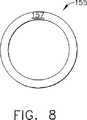
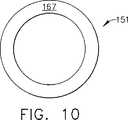
図5および図6はスプリング表面158を含むカラー・キャップ152を示している。図7および図8はキャップ表面部分156、ワッシャー表面部分157、および複数のスプリング要素159を含む力制限スプリング155を示している。この力制限スプリング155はそのスプリング要素159の形状によりウェーブ・スプリング(wave spring)として当該技術分野において説明されている。このようなウェーブ・スプリングを力制限スプリング155において使用することは、このスプリングが超音波外科器具の諸用途に良好に適合している小形の物理的寸法において高いばね率を示し、この場合に、その中心領域が超音波導波管179のために開口状態であるという理由により、有利である。力制限スプリング155はカラー・キャップ152のスプリング表面部分とワッシャー151のスプリング面部165との間においてバイアス力を受けている。ワッシャー151はクランプ式凝固装置120(図2乃至図4参照)の組み立て後にヨーク280の各爪286に接触する爪面部167(図9および図10)を有している。
【0036】
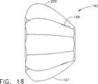
次に、図2および図14乃至図18において、回転ノブ190が上記の細長い部材150を回転するために当該細長い部材150に取り付けられていて、管状カラー260がヨーク280に対して回転するようになっている。この回転ノブ190はポリエーテルイミド、ナイロン等の別のプラスチック材料、またはその他の任意の適当な材料を含む種々の材料により作成することも可能である。
【0037】
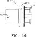
好ましくは、上記の回転ノブ190は拡大部分または外側ノブ192、内側ノブ194、およびこれらを貫通している軸方向のボア196を有している。内側ノブ194は外側ノブ192のキーウェイ189に協同的に取り付けるためのキー191を有している。外側ノブ192は交互に置かれている長手方向に沿う隆起部197および溝部198を有しており、これらは外科医による回転ノブ190および細長い部材150の配向を容易にする。この回転ノブ190の軸方向のボア196は細長い部材150の基端部上に適当に嵌合するように構成されている。
【0038】
内側ノブ194は器具ハウジング130の先端部における開口部139の中に延在している。この内側ノブ194は当該内側ノブ194を上記開口部139の中に回転可能に取り付けるためのチャンネル193を有している。さらに、上記の回転可能なノブ190の内側ノブ194は一対の対向している穴199を有している。これらの対向している各穴199は後に説明するような細長い部材150を貫通している通路195の一部分として整合されている。
【0039】
例えば、ピン163等の連結部材を上記通路195における対向している各穴199の中に配置できる。このピン163は、例えば、ハウジング130内のリブの間に捕捉するか、シリコーンまたはシアノアクリレート等の接着剤を含む任意の適当な手段により細長い部材150の通路195の中に保持できる。このピン163は細長い部材150を回転するために回転ノブ190から細長い部材150に回転トルクを供給することを可能にする。
【0040】
回転ノブ190を回転する場合に、管状カラー260の歯部269がヨーク280の対応する各爪286に係合して僅かに乗り上がる。これらの爪286が歯部269上に乗り上がると、ヨーク280の支持部材282が外側に偏向して各爪286が管状カラー260の歯部269の上を摺動して通過することを可能にする。
【0041】
実施形態の一例において、管状カラー260の歯部269は傾斜部または隆起部として構成されており、ヨーク280の各爪286はポスト部として構成されている。また、これらの管状カラー260の歯部269およびヨーク280の各爪286を逆にして、管状カラー260の歯部269をポスト部とし、ヨーク280の各爪286を傾斜部または隆起部とすることもできる。なお、上記の歯部269を細長い部材150の周縁部に一体に形成するか直接的に連結することも可能であると考えられる。さらに、上記の歯部269および各爪286は、本発明の趣旨および範囲から逸脱することなく、協同的な突出部分、隆起部分、カム面、ラチェット状の歯部、のこ歯部、隆起部、フランジ、または上記細長い部材150を選択的な角度位置に指定可能にするように協同作用するその他の類似手段にすることができることが認識されると考える。
【0042】
図2に示されているように、上記のクランプ式凝固装置120における細長い部材150は器具ハウジング130から延出している。図2B乃至図4に示されているように、細長い部材150は好ましくは外側部材または外側チューブ160、内側部材または内側チューブ170、および伝達部品または超音波導波管179を有している。
【0043】
上記の細長い部材150の外側チューブ160は好ましくはハブ162、管状部材164、およびこれらを貫通している長手方向の開口部または孔166を有している。また、この外側チューブ160は好ましくは実質的に円形の断面を有しており、ステンレス・スチールにより製造可能である。なお、この外側チューブ160が任意の適当な材料により構成可能であり、任意の適当な断面形状を有し得ることが認識されると考える。
【0044】
上記の外側チューブ160のハブ162は好ましくは管状部材164よりも大きい直径を有している。このハブ162はピン163を受容して当該ハブ162を回転ノブ190に対して連結可能にするための一対のチューブ穴161を有している。この結果、外側チューブ160は回転ノブ190が回転または回動する時に回転する。
【0045】
外側チューブ160のハブ162はさらに上記ハブ162の反対側の各面部にレンチ・フラット部169を有している。これらのレンチ・フラット部169は好ましくはハブ162の先端部の近くに形成されている。また、これらのレンチ・フラット部169はハブ162に対してトルク・レンチによりトルクを供給して超音波導波管179を音響組立体80のスタッド50に固定することを可能にする。例えば、本明細書に参考文献として含まれる米国特許第5,059,210号および同第5,057,119号はハンド・ピース組立体における取付装置に対して伝達部品を着脱するためのトルク・レンチを開示している。
【0046】
上記の外側チューブ160における管状部材164の先端部に、例えば、組織の把持、組織の切断等のような種々の作業を行うためのエンド−エフェクター180が配置されている。なお、このエンド−エフェクター180が任意の適当な構成に形成可能であることが考えられる。
【0047】
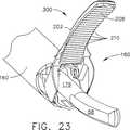
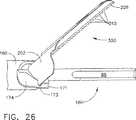
上記のエンド−エフェクター180およびその構成部品が図23乃至図33においてさらに詳細に示されている。このエンド−エフェクター180は一般に、例えば、組織を把持するため、またはブレード88に対して組織を押圧するための非振動性のクランプ・アーム組立体300を備えている。また、このエンド−エフェクター180は図23および図26においてクランプ開口状態で示されており、クランプ・アーム組立体300は好ましくは外側チューブ160の先端部に旋回可能に取り付けられている。
【0048】
先ず、図23乃至図26において、クランプ・アーム組立体300は好ましくはクランプ・アーム202、あご孔204、第1のポスト部206A、第2のポスト部206B、および組織パッド208を有している。クランプ・アーム202はピボット・ピン207Aおよびピボット・ピン207Bに対して旋回可能に取り付けられていて、親指用のループ142が図3において矢印121により示されている方向に移動する時に図3における矢印122の方向に回転する。旋回式のハンドル部分136を器具ハウジング130に向けて進行させることにより、クランプ・アーム202はピボット・ピン207Aおよびピボット・ピン207Bの回りに旋回して閉鎖状態になる。また、旋回式のハンドル部分136を後退して器具ハウジング130から離間させることにより、クランプ・アーム202が旋回して開口状態になる。
【0049】
クランプ・アーム202は超音波ブレード88とクランプ・アーム組立体300との間に組織を挟むために当該クランプ・アーム202に取り付けられている組織パッド208を有している。この組織パッド208は好ましくは高分子またはその他の柔軟な材料により形成されていて、クランプ・アーム202がその閉鎖状態にある時に超音波ブレード88に係合する。好ましくは、この組織パッド208は、例えば、ポリマー状のポリテトラフルオロエチレン(PTFE)に相当するE. I. Du Pont de Nemours and Companyの商標名であるTEFLON(R)(テフロン(R))のように、一定の低い摩擦係数を有しているが、組織の把持能力を示すために実質的に剛性である材料により形成されている。この組織パッド208は接着剤、好ましくは以下に説明するような機械的な固定構造によりクランプ・アーム202に取り付けることができる。
【0050】
図23、図26および図28において示されているように、のこ歯部210が組織パッド208のクランプ表面部に形成されていて、超音波ブレード88の軸に対して垂直に延在して、組織をクランプ・アーム202と超音波ブレード88との間において滑らせることなく組織の把持、操作、凝固および切断を可能にしている。
【0051】
組織パッド208は図27乃至図29にさらに詳細に示されている。この組織パッド208はT字形状の突出部212、左側突出面部214、右側突出面部216、上面部218、および下面部219を有している。下面部219は既に説明したのこ歯部210を有している。さらに、組織パッド208は以下に説明するような組み立て中における挿入を容易にするためのベベル状の前端部209を有している。
【0052】
図26において、上記内側チューブ170における管状部材174の先端部は好ましくは当該先端部から延出しているフィンガー部またはフランジ部171を有している。このフランジ部171はクランプ・アーム202の各ポスト部206Aおよびポスト部206Bをそれぞれ受容するための開口部173Aおよび開口部173B(173Bは図示せず)を有している。これにより、細長い部材150の内側チューブ170が軸方向に移動する時に、上記のフランジ部171がクランプ・アーム組立体300のポスト部206に係合しながら前方または後方に移動することによりクランプ・アーム202を開閉する。
【0053】
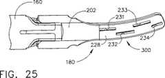
次に、図24、図25および図31乃至図33において、エンド−エフェクター180のクランプ・アーム202がさらに詳細に示されている。クランプ・アーム202はアーム上部228およびアーム下部230、ならびに、直線状部分235および湾曲状部分236を有している。直線状部分235は直線状のT字形スロット226を有している。また、湾曲状部分236は第1の上部穴231、第2の上部穴232、第3の上部穴233、第4の上部穴234、第1の下部切り欠き部241、第2の下部切り欠き部242、第3の下部切り欠き部243、第4の切り欠き部244、第1の棚部221、第2の棚部222、第3の棚部223、第4の棚部224、および第5の棚部225を有している。
【0054】
上記の穴231はアーム上部228からクランプ・アーム202を介して第2の棚部222まで延在している。また、上記の穴232はアーム上部228からクランプ・アーム202を介して第3の棚部223まで延在している。また、上記の穴233はアーム上部228からクランプ・アーム202を介して第4の棚部224まで延在している。さらに、上記の穴234はアーム上部228からクランプ・アーム202を介して第5の棚部225まで延在している。これらの各穴231乃至穴234および各棚部221乃至225棚部の配列構成によりクランプ・アーム202が上記の直線状部分235および湾曲状部分236の両方を備えることが可能になると共に、例えば、金属射出成形(MIM)等の方法により成形可能になる。クランプ・アーム202は上記のMIM法を利用することによりステンレス・スチールまたはその他の適当な金属により作成できる。
【0055】
図30および図31において、組織パッド208におけるT字形の突出部212はクランプ・アーム202のT字形スロット226の中に挿入可能である。クランプ・アーム202は、組織パッド208が、例えば、射出成形、機械加工、または押出成形等により直線状の部品として製造可能になるように設計されている。クランプ・アーム202においてその直線状のT字形スロット226の中に挿入されて湾曲状部分236の中に進行する時に、ベベル状の前端部209が組織パッド208の屈曲を容易にしてクランプ・アーム202の曲率に一致させる。さらに、各穴231乃至穴234および各棚部221乃至棚部225の配列構成により、クランプ・アーム202が組織パッド208を屈曲して保持することが可能になる。
【0056】
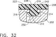
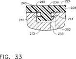
図32および図33はクランプ・アーム202が当該クランプ・アーム202の湾曲状部分236に対して一致している組織パッド208の屈曲状態を維持しながら組織パッド208を保持する方法を示している図である。図32に示されているように、第3の棚部223は右側突出面部216に接触して接触エッジ部238を形成しているが、左側の突出面部214はこの位置において支持されていない。一方、図33に示されている、先端側の位置においては、第4の棚部224が左側突出面部214に接触して接触エッジ部239を形成しているが、右側の突出面部216はこの位置において支持されていない。
【0057】
次に、図2に戻り、細長い部材150の内側チューブ170は外側チューブ160の開口部166の中に適当に嵌合している。この内側チューブ170は好ましくは内側ハブ172、管状部材174、外周溝176、一対の対向している開口部178、一対の対向している開口部168、およびこれらを貫通している長手方向の開口部または孔175を有している。この内側チューブ170は好ましくは実質的に円形の断面を有しており、ステンレス・スチールにより製造可能である。なお、この内側チューブ170が任意の適当な材料により構成可能であり、任意の適当な形状にできることが認識されると考える。
【0058】
上記の内側チューブ170における内側ハブ172は好ましくは上記の管状部材174よりも大きい直径を有している。また、この内側ハブ172における一対の対向している開口部178は内側ハブ172がピン163を受容可能にして、内側チューブ170および超音波導波管179が既に説明したように当該超音波導波管179をスタッド50に取り付けるためのトルクを伝達可能にしている。O−リング220は好ましくは内側ハブ172の外周溝176の中に配置されている。
【0059】
上記の細長い部材150における超音波導波管179は内側チューブ170の孔175の中に延在している。この超音波導波管179は好ましくは実質的に半柔軟性である。なお、この超音波導波管179が実質的に剛性であってもよく、また、柔軟性のワイヤ部材でもよいことが認識されると考える。これにより、超音波振動が超音波導波管179に沿って長手方向に伝達されて超音波ブレード88を振動させる。
【0060】
上記の超音波導波管179は、例えば、システム波長の1/2の整数倍(nλ/2)に実質的に等しい長さを有することができる。この超音波導波管179は好ましくはチタン合金(すなわち、Ti−6Al−4V)またはアルミニウム合金等の超音波エネルギーを効率的に伝搬する材料により構成されている中実コアの軸材により製造できる。なお、この超音波導波管179は任意の別の適当な材料により製造することも可能であることが考えられる。また、この超音波導波管179は当該技術分野において周知であるように上記の超音波ブレード88に伝達される機械的な振動を増幅することも可能である。
【0061】
図2に示すように、超音波導波管179は当該超音波導波管179の周縁部の周囲における種々の位置に配置されている1個以上の安定化用のシリコーン・リングまたは制振シース110(1個が示されている)を有することができる。この制振シース110は不所望な振動を制振して内側チューブ170からの超音波エネルギーを分離することにより、この超音波エネルギーを最大効率で超音波ブレード88の先端部まで長手方向に確実に伝達する。この減衰シース110は、例えば、本明細書に参考文献として含まれる米国特許出願第08/808,652号に記載されている減衰シースのように締り嵌めにより超音波導波管179に固定できる。
【0062】
さらに、図2において、超音波導波管179は一般に第1の部分182、第2の部分184、および第3の部分186を有している。この超音波導波管179の第1の部分182は当該超音波導波管179の基端部から先端側に延在している。この第1の部分182が実質的に連続的な一定の断面寸法を有している。
【0063】
上記第1の部分182は好ましくはその中を貫通している少なくとも1個の半径方向の穴188を有している。この導波管の穴188は超音波導波管179の軸に対して実質的に垂直に延在している。この導波管の穴188は好ましくは節部に配置されているが、超音波導波管179に沿う任意のその他の適当な位置に配置することも可能である。なお、この導波管の穴188が任意の適当な深さを有することができ、任意の適当な形状を有し得ることが認識されると考える。
【0064】
上記の第1の部分182における導波管の穴188はピン163を受容するために上記ハブ172において対向している各開口部178およびハブ162における外側チューブの各穴162に整合されている。ピン163は細長い部材150を回転するために回転トルクが回転ノブ190から超音波導波管179に加えられることを可能にする。細長い部材150における通路195は対向している各開口部178、外側チューブの各穴161、導波管の穴188、および対向している各穴199を含む。
【0065】
上記の超音波導波管179における第2の部分184は第1の部分182から先端側に延在している。この第2の部分184は実質的に連続的な一定の断面寸法を有している。この第2の部分184の直径は上記第1の部分182の直径よりも小さい。これにより、超音波エネルギーは超音波導波管179における第1の部分182から第2の部分184に伝達され、この第2の部分184において狭められている部分により当該部分を通過する超音波エネルギーの振幅が増幅される。
【0066】
さらに、上記の第3の部分186が上記第2の部分184の先端部から先端側に延在している。この第3の部分186は実質的に連続的な一定の断面寸法を有している。また、この第3の部分186はその長さに沿って変化している小さい直径を有することも可能である。この第3の部分は好ましくは当該第3の部分186の外周縁部の周囲に形成されているシール187を有している。これにより、超音波エネルギーは超音波導波管179における第2の部分184から上記第3の部分の中に伝達され、この第3の部分186において狭められている部分により当該部分を通過する超音波エネルギーの振幅が増幅される。
【0067】
上記の第3の部分186はその外周部分に形成されている複数の溝部またはノッチ部(図示せず)を有することができる。これらの溝部は製造中において制振シース110を備え付けるための整合指示手段として作用するために超音波導波管179の各節部または当該超音波導波管179に沿う任意の別の適当な位置に配置することが可能である。
【0068】
さらに、図2において、上記外科器具150における制振シース110は超音波導波管179の少なくとも一部分を囲っている。この制振シース110は超音波導波管179の周囲に配置されて、動作中における超音波導波管179の横方向の側面から側面に到る振動を制振または制限することができる。この制振シース110は好ましくは超音波導波管179の第2の部分184の一部を囲っている。なお、この制振シース110が超音波導波管179における任意の適当な部分の周囲に配置可能であることも考えられる。また、この制振シース110は好ましくは横方向の振動における少なくとも1個の波腹部、さらに好ましくは横方向の振動における複数の波腹部において延在している。さらに、この制振シース110は好ましくは実質的に円形の断面を有している。なお、この制振シース110が超音波導波管179上に嵌合する任意の適当な形状を有することができ、任意の適当な長さを有し得ることが認識されると考える。
【0069】
制振シース110は好ましくは超音波導波管179に軽く接触して超音波導波管179からの不所望な超音波エネルギーを吸収する。この制振シース110は55,500Hzの長手方向の周波数ならびにそれ以上およびそれ以下の周波数に付随する不所望な横方向の振動を含む超音波導波管179の軸方向以外の振動の振幅を減少する。
【0070】
上記の制振シース110は超音波導波管179の軸方向の動作すなわち長手方向の振動によるエネルギーの消失を最少にするために、好ましくは一定の低摩擦係数を有する高分子材料により構成されている。この高分子材料は好ましくはフロウラ−エチレン・プロペン(floura-ethylene propene)(FEP)であり、この材料はガンマ放射線による滅菌処理における崩壊に対して耐性を有している。なお、上記の制振シース110が、例えば、PTFE等の任意の適当な材料により製造可能であることが認識されると考える。
【0071】
上記の制振シース110は好ましくはこれを貫通する開口部、および長手方向のスリット111を有している。この制振シース110のスリット111は制振シース110がいずれの端部からも超音波導波管179の上に組み合わせられることを可能にしている。なお、この制振シース110が当該制振シース110を超音波導波管179の上に嵌合可能にする任意の適当な構成を有し得ることが認識されると考える。例えば、この制振シース110はコイルとしてまたは螺旋状に形成することができ、あるいは長手方向および/または外周方向のスリットまたはスロットの種々のパターンを有することができる。さらに、この制振シース110がスリット111無しで製造可能であること、および超音波導波管179が制振シース110の中に嵌合するための2個以上の部品により製造可能であることも考えられる。
【0072】
上記の超音波導波管179が任意の適当な断面寸法を有し得ることが認識されると考える。例えば、この超音波導波管179は実質的に均一な断面を有していてもよく、また、この超音波導波管179は種々の部分においてテーパー状であってもよく、あるいはその全長にわたってテーパー状であってもよい。
【0073】
また、上記の超音波導波管179は当業界において周知のように当該超音波導波管179を介して超音波ブレード88に伝達される機械的な振動を増幅することもできる。さらに、この超音波導波管179は当該超音波導波管179に沿う長手方向の振動の利得を制御するための特徴部分および当該超音波導波管179をシステムの共振振動数に同調するための特徴部分を有することができる。
【0074】
上記の超音波導波管179における第3の部分186の基端部は好ましくは波腹部の近くにおいて内部のねじ付き接続手段により上記第2の部分184の先端部に連結することができる。なお、この第3の部分186が溶接接合等の任意の適当な手段により上記第2の部分184に取り付け可能であると考えられる。この第3の部分186は超音波ブレード88を含む。この超音波ブレード88は超音波導波管179から分離可能にすることができるが、この超音波ブレード88および超音波導波管179は単一ユニットとして形成されていることが好ましい。
【0075】
上記の超音波ブレード88はシステム波長の1/2の整数倍(nλ/2)に実質的に等しい長さを有することができる。また、この超音波ブレード88の先端部は当該先端部における最大の長手方向の偏位を行うために波腹部の近くに配置することができる。これにより、上記のトランスデューサ組立体が励起されると、超音波ブレード88の先端部は所定の振動周波数において、例えば、約10ミクロン乃至500ミクロンのピーク−トゥ−ピーク動作、好ましくは約30ミクロン乃至150ミクロンの範囲内で移動するように構成される。
【0076】
上記の超音波ブレード88は好ましくはチタン合金(すなわち、Ti−6Al−4V)またはアルミニウム合金等の超音波エネルギーを伝搬する材料により構成されている中実コアの軸材により作成されている。なお、この超音波ブレード88が任意の別の適当な材料により製造できることが認識されると考える。さらに、この超音波ブレード88がエネルギーの供給および所望の組織作用を改善するための表面処理を有し得ることも考えられる。例えば、この超音波ブレード88は凝固性および組織の切断能力を高めるため、および/または、組織および血液のエンド−エフェクターに対する付着性を減少するために、微細仕上げ、コーティング処理、めっき処理、エッチング処理、グリット・ブラスト仕上げ、粗面化またはスコア処理することができる。加えて、この超音波ブレード88はその諸特性を高めるために鋭利化または付形処理することができる。例えば、この超音波ブレード88はブレード形状、フック形状、またはボール形状にすることができる。
【0077】
図34、図35および図36に示すように、本発明による超音波ブレード88の形状は既存の装置よりもさらに均一にクランプした組織に超音波出力を供給する。エンド−エフェクター180はブレード末端部分の改善された可視性を提供するので、外科医はブレード88が切断または凝固されている構造を横切って延在していることを確認できる。このことは特に大血管の縁を確認する場合に重要である。また、この形状は生物学的な諸構造の湾曲部分にさらに似せることによりさらに改善された組織への接近能力も提供する。このブレード88は多数の組織作用、すなわち、クランプ状態の凝固、クランプ状態の切断、把持、背部切断、切開、スポット凝固、末端部分の浸透および末端部分のスコア処理等を行うように設計されている多数のエッジ部分および表面部分を備えている。
【0078】
ブレード88の最先端部分は接線63、すなわち、当該先端部分における湾曲部分に対して接している線に対して垂直な表面部分54を有している。また、2個のすみ肉状の特徴部分61Aおよび特徴部分61Bが各表面部分51,52および54を混合するために使用されており、これによりスポット凝固に利用できる鈍い先端部分が形成されている。また、ブレード88の上部は丸み付けまたは鈍化されていて、当該ブレード88とクランプ・アーム組立体300との間に組織をクランプするための広いエッジ部分または表面部分56を形成している。この表面部分56はクランプ状態での切断処理および凝固処理のために使用されると共に、ブレードの不活性時に組織を操作するためにも使用される。
【0079】
また、下面部はブレード88の底部に沿って狭いエッジ部すなわち鋭いエッジ部55を形成している球面状の切断部分53を有している。このような材料の切断は、例えば、半径R1の円弧状に球面端部のミルを掃引した後にブレード88の底面部58に上記の切断部分を混合するさらに狭い第2の半径R2によりこの切断部分を仕上げすることにより達成できる。上記の半径R1は好ましくは0.5インチ乃至2インチ(1.27cm乃至5.08cm)の範囲内、さらに好ましくは0.9インチ乃至1.1インチ(2.29cm乃至2.79cm)の範囲内、最も好ましくは約1.068インチ(2.713cm)である。また、上記の半径R2は好ましくは0.125インチ乃至0.5インチ(0.318cm乃至1.27cm)、最も好ましくは約0.25インチ(0.64cm)である。この第2の半径R2およびこれに対応するブレード88の底面部58との混合部分はこの混合部分の無い切断状態で停止する場合に比べてその球面状の切断部分の端部に集中する応力を減少する。上記の鋭いエッジ部55は脈管の少ない組織の中の切開および非クランプ状態の切断(背部切断)を容易にする。
【0080】
さらに、上記ブレード88の湾曲形状は組織が当該ブレード88に対してクランプされている時にその組織に対して比較的に均一に分布されているエネルギー供給を生じる。このような均一なエネルギー供給はエンド−エフェクター180の長さに沿う一定の組織作用(熱的および横断作用)が達成できる点で望ましい。ブレード88の最先端の15ミリメートルの部分は作用部分であり、一定の組織作用を達成するために用いられる。この湾曲状のシャー・ブレード88に沿う各位置における変位ベクトルは既存の器具に優る本発明の種々の改善により図34に示すようなx−y平面内に主に存在している各方向を有する。それゆえ、ブレード88の動作はクランプ・アーム組立体300からのクランプ力の方向に対して垂直な平面(上記のx−y平面)内に存在している。
【0081】
上記ブレード88の底面部58における球面状の切断部分53は鋭いエッジ部55を形成すると共にブレード88から最小量の材料を除去している。このブレード88の底部における球面状の切断部分53は以下に説明するように一定の角度αを有する鋭いエッジ部55を形成している。この角度αは、例えば、オハイオ州、シンシナティーのEthicon Endo-Surgery社により製造されているLCS-K5のような既存のシャー装置と同様にできる。しかしながら、本発明のブレード88はその一般的な供給力に関して上記の角度αの配向により既存の装置よりも速く切断することができる。既存のシャー装置の場合には、その各エッジ部が対称形であり、その供給力を均等に広げる。一方、本発明の場合の各エッジ部は非対称であって、このエッジ部の非対称性が組織の分離または切断における速度の高さを示す。すなわち、この非対称性は鈍化した形状を維持しながら大きな容量の材料を除去することなく超音波により活性化される時に効果的にさらに鋭いエッジ部を提供することにおいて重要である。また、この非対称形の角度ならびに上記ブレードの湾曲部分は僅かなフック状のまたは楔状の作用により背部切断中にそれ自体で組織に張力を加えるように作用する。
【0082】
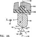
超音波ブレード88の鋭いエッジ部55は表面部分53と底面部58が球面状の切断部分53を受容した後に残された第2の表面部分57との交線により定められる。クランプ・アーム組立体300は超音波ブレード88に対して旋回移動して当該クランプ・アーム組立体300と超音波ブレード88との間に組織をクランプするために外側チューブ160の先端部に旋回可能に取り付けられている。この結果、内側チューブ170の往復移動によりクランプ・アーム組立体300が円弧状に旋回して垂直平面181が定められる。鋭いエッジ部55における球面状の切断部分53の接線60は図35に示されているように第2の表面部分57の接線62に対して一定の角度αを定めている。この角度αの二等分線59は好ましくは上記の垂直平面181内に存在せずに、角度βだけずれている。好ましくは、上記球面状の切断部分53の接線60は垂直平面181に対して約5度乃至50度の範囲内で存在しており、最も好ましくは、この球面状の切断部分53の接線は垂直平面181から約38.8度で存在している。好ましくは、上記角度αは約90度乃至150度の範囲内であり、最も好ましくは、この角度αは約121.6度である。
【0083】
図35Aにおいて、本発明の別の実施形態が非対称な狭いエッジ部を伴って示されている。鋭いエッジ部55Aにおける球面状の切断部分53Aの接線60Aは図35Aに示されているように第2の表面部分57Aの接線62Aに対して一定の角度αAを定めている。この角度αAの二等分線59Aは好ましくは垂直平面181A内に存在しておらず、一定の角度βAだけずれている。
【0084】
次に、図1乃至図4において、上記のクランプ式凝固装置120を音響組立体80に対して着脱するための手順を以下に説明する。医者がクランプ式凝固装置120を使用する準備ができると、この医者はそのクランプ式凝固装置120を音響組立体80に単純に取り付ける。このクランプ式凝固装置120を音響組立体80に取り付けるためには、スタッド50の先端部を伝達部品すなわち超音波導波管179の基端部にねじにより接続する。その後、このクランプ式凝固装置120を慣用的なねじ締め方向に手動で回転して、スタッド50と超音波導波管179との間のねじ接合部分をインターロックする。
【0085】
超音波導波管179をスタッド50にねじにより接合した後に、例えば、トルク・レンチのような工具をクランプ式凝固装置120の細長い部材150の上に配置して超音波導波管179をスタッド50に対して締め付ける。この工具は外側チューブ160におけるハブ162のレンチ・フラット部分169に係合して超音波導波管179をスタッド50上に固定するように構成できる。この結果、ハブ162の回転により、超音波導波管179が所望且つ所定のトルクでスタッド50に対して固定されるまで細長い部材150が回転される。なお、上記のトルク・レンチがクランプ式凝固装置120の一部分として、または本明細書に参考文献として含まれる米国特許第5,776,155号に記載されているトルク・レンチのように、ハンド・ピース・ハウジング20の一部分として別に製造可能であることが考えられる。
【0086】
クランプ式凝固装置120を音響組立体80に取り付けた後に、外科医は回転ノブ190を回転して細長い部材150を所望の角度位置に調節することができる。回転ノブ190を回転している時に、管状カラー260の歯部269がヨーク280の各爪286の上を摺動して隣接するノッチ部または谷部の中に入る。この結果、外科医はエンド−エフェクター180を所望の配向に位置決めできる。回転ノブ190は器具ハウジング130とクランプ・アーム202との間の回転方向の関係を指定するための指定手段を組み込むことができる。図17および図18に示されているように、例えば、拡大された隆起部200を利用することにより、回転ノブ190における隆起部197の内の1個を器具ハウジング130に対するクランプ・アーム202の回転方向の位置を指定するために使用できる。なお、拡大された隆起部200の使用と同様に位置を指定するために、色、シンボル、表面模様等の使用を含む別の指定手段を回転ノブ190において用いることも可能であると考えられる。
【0087】
音響組立体80のスタッド50からクランプ式凝固装置120を分離するためには、この外科器具120の細長い部材150上に上記の工具を摺動してこれを反対方向、すなわち、超音波導波管179をスタッド50に対するねじ係合から解除する方向に回転することができる。この工具を回転すると、外側チューブ160のハブ162はトルクがピン163を介して超音波導波管179に加えられることを可能にして、比較的高い係合解除用のトルクが超音波導波管179をそのねじ係合解除の方向に回転するように加えられる。この結果、超音波導波管179はスタッド50から緩み離れる。このようにして超音波導波管179がスタッド50から取り外された後に、クランプ式凝固装置全体が放出可能になる。
【0088】
以上、本発明の好ましい実施形態を本明細書において図示し説明したが、当該技術分野における熟練者においては、これらの各実施形態が例示的な目的のみにより提供されていることが明らかになる。すなわち、この時点において、多数の変形、変更、および置換が本発明から逸脱することなく当該技術分野における熟練者において考え出されるようになる。従って、本発明は本明細書に記載する特許請求の範囲における趣旨および範囲のみにより制限されるべきであると考える。
本発明の新規な特徴は特に本明細書における特許請求の範囲において記載されている。しかしながら、本発明自体は、その構成および動作方法の両方について、そのさらに別の目的および利点と共に、以下の添付図面と共にその詳細な説明を参考にすることにより最良に理解できる。
【図面の簡単な説明】
【図1】 超音波発生器の平面図、超音波トランスデューサの断面図、および本発明によるクランプ式凝固装置の部分断面図を含む超音波外科システムを示している。
【図2A】 本発明によるクランプ式凝固装置の一部分の分解斜視図である。
【図2B】 本発明によるクランプ式凝固装置の一部分の分解斜視図である。
【図3】 開口状態で示されているクランプ・アーム組立体を伴う本発明によるクランプ式凝固装置の部分断面図である。
【図4】 閉鎖状態で示されているクランプ・アーム組立体を伴う本発明によるクランプ式凝固装置の部分断面図である。
【図5】 上記クランプ式凝固装置におけるカラー・キャップの側面図である。
【図6】 上記クランプ式凝固装置におけるカラー・キャップの正面図である。
【図7】 上記クランプ式凝固装置における力制限用スプリングの側面図である。
【図8】 上記クランプ式凝固装置における力制限用スプリングの正面図である。
【図9】 上記クランプ式凝固装置におけるワッシャーの側面図である。
【図10】 上記クランプ式凝固装置におけるワッシャーの正面図である。
【図11】 上記クランプ式凝固装置における管状カラーの側面図である。
【図12】 上記クランプ式凝固装置における管状カラーの後面図である。
【図13】 上記クランプ式凝固装置における管状カラーの正面図である。
【図14】 上記クランプ式凝固装置における内側ノブの側面図である。
【図15】 上記クランプ式凝固装置における内側ノブの正面図である。
【図16】 上記クランプ式凝固装置における内側ノブの下面図である。
【図17】 上記クランプ式凝固装置における外側ノブの後面図である。
【図18】 上記クランプ式凝固装置における外側ノブの上面図である。
【図19】 上記クランプ式凝固装置におけるヨークの上面図である。
【図20】 上記クランプ式凝固装置におけるヨークの側面図である。
【図21】 上記クランプ式凝固装置におけるヨークの正面図である。
【図22】 上記クランプ式凝固装置におけるヨークの斜視図である。
【図23】 上記クランプ式凝固装置におけるエンド−エフェクターの斜視図である。
【図24】 上記クランプ式凝固装置におけるクランプ・アームの上部斜視図である。
【図25】 上記クランプ式凝固装置におけるエンド−エフェクターの上面図である。
【図26】 クランプ・アームが開口状態である上記クランプ式凝固装置におけるエンド−エフェクターの側面図である。
【図27】 上記クランプ式凝固装置における組織パッドの上面図である。
【図28】 上記クランプ式凝固装置における組織パッドの側面図である。
【図29】 上記クランプ式凝固装置における組織パッドの正面図である。
【図30】 上記クランプ式凝固装置における組織パッドの斜視図である。
【図31】 上記クランプ式凝固装置におけるクランプ・アームの下部斜視図である。
【図32】 図31に示されているクランプ・アームの第1の断面図である。
【図33】 図31に示されているクランプ・アームの第2の断面図である。
【図34】 上記クランプ式凝固装置におけるブレードの下面図である。
【図35】 上記クランプ式凝固装置におけるブレードの断面図である。
【図35A】 上記クランプ式凝固装置の別の実施形態におけるブレードの断面図である。
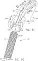
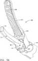
【図36】 上記クランプ式凝固装置におけるエンド−エフェクターの斜視図である。
【符号の説明】
10 超音波システム
15 超音波信号発生器
20 ハンド・ピース・ハウジング
80 音響組立体
82 超音波トランスデューサ
120 クランプ式凝固装置
130 器具ハウジング
150 細長い部材
179 超音波導波管
180 エンド−エフェクター
300 クランプ・アーム組立体[0001]
Field of Invention
The present invention relates generally to ultrasonic surgical clamping instruments, and more particularly to a multifunctional curved shear blade for ultrasonic surgical clamping instruments.
[0002]
Background of the Invention
This patent application includes the following co-pending patent applications: US patent application Ser. No. 08 / 948,625 filed Oct. 10, 1997, No. 08 filed Oct. 10, 1997. No./949,133, 09 / 106,686 filed on June 29, 1998, 09 / 337,077 filed on June 21, 1999, 09 / 412,557, 09 / 412,996, and 09 / 412,257, which are incorporated herein by reference.
[0003]
Ultrasound instruments, including hollow core and solid core instruments, are used for the safe and effective treatment of many medical conditions. Ultrasound instruments, particularly solid core ultrasound instruments, are used to cut and / or coagulate organic tissue using energy in the form of mechanical vibrations that are transmitted to the surgical end-effector at ultrasonic frequencies This is advantageous. Ultrasonic vibration can be used to cut, incise, or cauterize tissue when transmitted to organic tissue at an appropriate energy level and using an appropriate end-effector. Ultrasonic instruments that utilize solid core techniques are particularly advantageous because of the amount of ultrasonic energy that can be transmitted from the ultrasonic transducer through the waveguide to the surgical end-effector. These instruments are particularly suitable for use in minimally invasive procedures, including endoscopic or laparoscopic procedures, where the end-effector reaches the surgical site through the trocar.
[0004]
Ultrasonic vibrations are induced in the surgical end-effector by electrically exciting a transducer that can be comprised of, for example, one or more piezoelectric transducer elements or magnetostrictive elements in the instrument hand piece. Vibrations generated by the transducer portion are transmitted to the surgical end-effector via an ultrasonic waveguide that extends from the transducer portion to the surgical end-effector.
[0005]
Solid core ultrasonic surgical instruments can be divided into two types of devices: single-element end-effector devices and multi-element end-effectors. Single element end-effector devices include instruments such as surgical scalpels and ball coagulators, see, eg, US Pat. No. 5,263,957. While instruments such as those disclosed in US Pat. No. 5,263,957 are known to be quite satisfactory, there are some limitations in their use as well as in other ultrasonic surgical instruments. is there. For example, single element end-effector devices have limited ability to apply pressure from the blade to the tissue when the tissue is soft and gently supported. Sufficient pressure is required to effectively transmit ultrasonic energy to the tissue. If the tissue cannot be reliably captured in this manner, it cannot be completely adhered to the tissue surface during the supply of ultrasonic energy, resulting in insufficient hemostasis and tissue bonding.
[0006]
The use of multi-element end-effectors, such as clamp coagulators, includes a mechanism for pressing tissue against an ultrasonic blade, which eliminates the disadvantages described above. Clamping mechanisms disclosed as useful in ultrasonic surgical devices are described in US Pat. Nos. 3,636,943 and 3,862,630 issued to Balamuth. In general, however, the Balamuth apparatus disclosed in these patents does not solidify and cut at a sufficient rate, and the approach to the blade is blocked by the clamp and cannot be used for cutting / coagulation without the clamp. Lack of flexibility.
[0007]
For example, ultrasonically clamped coagulation devices such as those disclosed in US Pat. Nos. 5,322,055 and 5,893,835 are gently supported or not supported at all. An improved ultrasonic surgical instrument for cutting / coagulating tissue is provided, where an ultrasonic blade is used in conjunction with a clamp to apply a constant compressive or biasing force to the tissue. Thus, relatively fast tissue coagulation and cutting can be achieved, and blade motion attenuation can be relatively reduced.
[0008]
An improvement in the technique of curved ultrasound instruments as described in US patent application Ser. No. 09 / 106,686, previously incorporated herein by reference, is another aspect of curved clamped coagulation. It shows the need for improvement in the device. For example, US Pat. No. 5,873,873 describes an ultrasonically clamped coagulation instrument that includes an end-effector that includes a clamp arm having a tissue pad. In the configuration disclosed in US Pat. No. 5,873,873, the clamp arm and tissue pad are straight.
[0009]
The shape of the ultrasonic surgical blade or end-effector used in the clamp coagulator defines at least four important aspects of the instrument. These are (1) the visibility of the end-effector and its relative position within the surgical field, (2) the ability of the end-effector to approach or enter the targeted tissue, and (3) the ultrasonic energy is cut off. And (4) the manner in which the tissue can be manipulated by an ultrasonically inert end-effector. Therefore, it would be advantageous to provide an improved ultrasonic clamp coagulator that optimizes these four aspects of the instrument.
[0010]
Idemoto et al. Discloses a surgical ultrasonic horn for use in surgery comprising a horn body portion and an end plate portion. Cut portions are provided at the edges and ends of the end portions. In addition, a passage for the stimulation solution extends into the horn body portion and the end plate portion. At least one bore opens in the cut portion at an injection angle of 5 to 90 degrees with respect to the plane of the end plate portion. The stimulation solution passage is in communication with the bore so that the stimulation solution is sprayed therethrough.
[0011]
It would be advantageous to deliver ultrasonic power to tissue that is clamped more uniformly than existing devices. It would also be advantageous to provide the surgeon with the ability to provide improved visibility of the end-effector to ensure that the blade extends across the structural portion to be cut / coagulated. It would also be advantageous to provide improved tissue access by an end-effector that further resembles the curved portion of each biological structural portion. In addition, multiple edge portions and It would also be advantageous to have a surface portion. It would also be advantageous to provide an ultrasonically clamped coagulation device that can utilize a slight hook-like or wedge-like action to tension tissue on its own during a back cut. In addition, using specially shaped parts including compatibility with clamp members, sharp features for cutting, curved parts for accessibility and visibility, and a more uniform ultrasonic power supply than existing devices It would also be advantageous to provide a multifunctional ultrasonic surgical blade. The present invention provides these features and improvements as described below.
[0012]
Summary of the Invention
The present invention discloses an ultrasonic surgical instrument that combines the shape of the end-effector to best perform the numerous functions of the shear configuration. The blade shape is characterized by a rounded cut to form a curved and potentially tapered shaped portion. In the example of the embodiment, the cut portion forms a curved surface portion including a concave surface portion and a convex surface portion. This convex surface portion has changed to a short, straight, flat surface portion. The length of this straight section will act in part in the acoustical balancing of the lateral motion induced by the curved shape described above. Compared to a straight blade end portion, the curved shape of the end portion according to the present design provides improved visibility at the crossing site and improved access to the targeted tissue. In one example embodiment, an ultrasonic blade is described having a wide edge portion and a narrow edge portion. The wide edge portion is on the opposite side of the narrow edge portion along a certain vertical plane, and the narrow edge portion is defined by the line of intersection of the first surface portion and the second surface portion. The first surface portion is concave.
[0013]
Detailed Description of the Invention
Hereinafter, the present invention will be described in combination with an ultrasonic instrument as described herein. This description is merely exemplary and is not intended to limit the scope and application of the present invention. For example, the present invention relates to US Pat. Nos. 5,938,633, 5,935,144, 5,944,737, 5,322,055, and 5,630,420. And in combination with a number of ultrasonic instruments including those described in US Pat. No. 5,449,370.
[0014]
FIG. 1 shows an
[0015]
The distal end portion of the
[0016]
The
[0017]
The
[0018]
Each
[0019]
In order for the
[0020]
Each component in the
[0021]
2A and 2B, a clamped
[0022]
Preferably, the
[0023]
The
[0024]
The
[0025]
The
[0026]
The
[0027]
The
[0028]
The
[0029]
Returning now to FIGS. 2A-4, the
[0030]
Returning now to FIG. 2A, the
[0031]
The
[0032]
The
[0033]
As shown in FIGS. 3 and 4, the
[0034]
5-10, the
[0035]
FIGS. 5 and 6 show a
[0036]
2 and 14-18, a
[0037]
Preferably, the
[0038]
[0039]
For example, a connecting member such as a
[0040]
When the
[0041]
In an example embodiment, the
[0042]
As shown in FIG. 2, the
[0043]
The
[0044]
The
[0045]
The
[0046]
An end-
[0047]
The above end-
[0048]
23-26, the
[0049]
The
[0050]
As shown in FIGS. 23, 26, and 28, the
[0051]
[0052]
In FIG. 26, the distal end portion of the
[0053]
24, 25 and 31-33, the
[0054]
The
[0055]
In FIGS. 30 and 31, the T-shaped
[0056]
FIGS. 32 and 33 show how the
[0057]
Returning now to FIG. 2, the
[0058]
The inner hub 172 in the
[0059]
The
[0060]
The
[0061]
As shown in FIG. 2, the
[0062]
Further, in FIG. 2, the
[0063]
The
[0064]
The waveguide holes 188 in the
[0065]
The
[0066]
Further, the
[0067]
The
[0068]
Further, in FIG. 2, the damping
[0069]
The damping
[0070]
The damping
[0071]
The damping
[0072]
It will be appreciated that the
[0073]
The
[0074]
The proximal end of the
[0075]
The
[0076]
The
[0077]
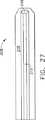
As shown in FIGS. 34, 35 and 36, the shape of the
[0078]
The most distal portion of the
[0079]
Further, the lower surface portion has a
[0080]
In addition, the curved shape of the
[0081]
The
[0082]
The
[0083]
In FIG. 35A, another embodiment of the present invention is shown with an asymmetric narrow edge. The tangent 60A of the
[0084]
Next, a procedure for attaching and detaching the clamp-
[0085]
After the
[0086]
After attaching the
[0087]
To separate the clamped
[0088]
While preferred embodiments of the invention have been illustrated and described herein, it will be apparent to those skilled in the art that these embodiments are provided for illustrative purposes only. That is, at this point, numerous variations, modifications, and substitutions will be conceived by those skilled in the art without departing from the present invention. Accordingly, the invention is to be limited only by the spirit and scope of the appended claims.
The novel features of the invention are set forth with particularity in the appended claims. However, the present invention itself, together with further objects and advantages thereof, may be best understood by reference to the detailed description taken in conjunction with the following accompanying drawings, both as to its configuration and method of operation.
[Brief description of the drawings]
FIG. 1 illustrates an ultrasonic surgical system including a plan view of an ultrasonic generator, a cross-sectional view of an ultrasonic transducer, and a partial cross-sectional view of a clamped coagulator according to the present invention.
FIG. 2A is an exploded perspective view of a portion of a clamped coagulator according to the present invention.
FIG. 2B is an exploded perspective view of a portion of the clamped coagulator according to the present invention.
FIG. 3 is a partial cross-sectional view of a clamp coagulator according to the present invention with a clamp arm assembly shown in an open state.
FIG. 4 is a partial cross-sectional view of a clamp coagulator according to the present invention with a clamp arm assembly shown in a closed state.
FIG. 5 is a side view of a color cap in the clamp type solidification apparatus.
FIG. 6 is a front view of a color cap in the clamp type solidification apparatus.
FIG. 7 is a side view of a force limiting spring in the clamp type solidification apparatus.
FIG. 8 is a front view of a force limiting spring in the clamp type solidification apparatus.
FIG. 9 is a side view of a washer in the clamp type solidification apparatus.
FIG. 10 is a front view of a washer in the clamp-type solidification device.
FIG. 11 is a side view of a tubular collar in the clamp type coagulation apparatus.
FIG. 12 is a rear view of the tubular collar in the clamp type coagulator.
FIG. 13 is a front view of a tubular collar in the clamp-type solidification device.
FIG. 14 is a side view of an inner knob in the clamp-type solidification device.
FIG. 15 is a front view of an inner knob in the clamp-type solidification device.
FIG. 16 is a bottom view of the inner knob in the clamp-type solidification device.
FIG. 17 is a rear view of the outer knob in the clamp-type solidification device.
FIG. 18 is a top view of an outer knob in the clamp-type solidification device.
FIG. 19 is a top view of a yoke in the clamp type solidification apparatus.
FIG. 20 is a side view of a yoke in the clamp type solidification apparatus.
FIG. 21 is a front view of a yoke in the clamp-type solidification device.
FIG. 22 is a perspective view of a yoke in the clamp type solidification apparatus.
FIG. 23 is a perspective view of an end-effector in the clamp type coagulation apparatus.
FIG. 24 is a top perspective view of a clamp arm in the clamp-type solidification device.
FIG. 25 is a top view of an end-effector in the clamp type coagulation apparatus.
FIG. 26 is a side view of the end-effector in the clamp type coagulation apparatus in which the clamp arm is in an open state.
FIG. 27 is a top view of a tissue pad in the clamp type coagulation apparatus.
FIG. 28 is a side view of a tissue pad in the clamp type coagulation apparatus.
FIG. 29 is a front view of a tissue pad in the clamp type coagulation apparatus.
FIG. 30 is a perspective view of a tissue pad in the clamp type coagulation apparatus.
FIG. 31 is a lower perspective view of a clamp arm in the clamp type solidification apparatus.
32 is a first cross-sectional view of the clamp arm shown in FIG. 31. FIG.
33 is a second cross-sectional view of the clamp arm shown in FIG. 31. FIG.
FIG. 34 is a bottom view of a blade in the clamp type solidification apparatus.
FIG. 35 is a cross-sectional view of a blade in the clamp type solidification apparatus.
FIG. 35A is a cross-sectional view of a blade in another embodiment of the clamp-type solidification device.
FIG. 36 is a perspective view of an end-effector in the clamp type coagulation apparatus.
[Explanation of symbols]
10 Ultrasonic system
15 Ultrasonic signal generator
20 Hand piece housing
80 Acoustic assembly
82 Ultrasonic transducer
120 Clamp type coagulator
130 Instrument housing
150 elongated member
179 Ultrasonic Waveguide
180 End-effector
300 Clamp arm assembly
Claims (23)
Translated fromJapaneseアクチュエータを有するハウジングと、
前記ハウジングの中に配置されている超音波導波管を備えており、当該超音波導波管が前記ハウジングから先端側に延在している湾曲したエンド−エフェクターを有しており、
前記エンド−エフェクターがエッジ部分を有しており、当該エッジ部分が第1の表面部分と第2の表面部分との交線により定められていて、当該第1の表面部分が凹状であり、第2の表面部分が凸状であり、さらに、
前記ハウジングに旋回可能に取り付けられている湾曲したクランプ・アームを備えており、このクランプ・アームが当該クランプ・アームと前記エッジ部分に対向している前記エンド−エフェクターの第3の表面部分との間に組織をクランプするために当該エンド−エフェクターに対して旋回可能であり、さらに、
前記ハウジング内において作動機構を備えており、当該作動機構が前記クランプ・アームと前記アクチュエータとの間に接続されており、さらに、当該作動機構が前記クランプ・アームを前記エンド−エフェクターに対して旋回可能に作動するように構成されている超音波クランプ式凝固装置。In the ultrasonic clamp type coagulator,
A housing having an actuator;
An ultrasonic waveguide disposed in the housing, the ultrasonic waveguide having a curved end-effector extending from the housing toward the distal end;
The end-effector has an edge portion, the edge portion is defined by a line of intersection of the first surface portion and the second surface portion, the first surface portion is concave, The surface portion of 2 is convex, and
A curved clamp arm pivotally attached to the housing, the clamp arm being connected to the clamp arm and a third surface portion of the end-effector facing the edge portion; Pivotable relative to the end-effector to clamp tissue therebetween, and
An actuating mechanism is provided in the housing, the actuating mechanism is connected between the clamp arm and the actuator, and the actuating mechanism pivots the clamp arm with respect to the end-effector. An ultrasonically clamped coagulatorconfigured to operateas possible.
アクチュエータを有するハウジングと、
前記ハウジングに結合している基端部、および先端部を有する外側チューブを備えており、当該外側チューブが長手軸を定めており、さらに、
前記外側チューブの中に往復動可能に配置されている作動要素を備えており、当該作動要素が前記アクチュエータに操作可能に接続しており、さらに、
前記外側チューブの中に配置されている超音波導波管を備えており、当該超音波導波管が前記外側チューブの先端部から先端側に延在している湾曲したエンド−エフェクターを有しており、
当該エンド−エフェクターがエッジ部分を有しており、当該エッジ部分が第1の表面部分と第2の表面部分との交線により定められていて、当該第1の表面部分が凹状であり、第2の表面部分が凸状であり、さらに、
前記外側チューブの先端部に旋回可能に取り付けられている湾曲したクランプ・アームを備えており、このクランプ・アームが当該クランプ・アームと前記エッジ部分に対向している前記エンド−エフェクターの第3の表面部分との間に組織をクランプするために当該エンド−エフェクターに対して旋回可能であり、当該クランプ・アームが前記作動要素に操作可能に接続していて当該作動要素の往復移動によりクランプ・アームが旋回し、さらに、
前記ハウジング内において作動機構を備えており、当該作動機構が前記クランプ・アームと前記アクチュエータとの間に接続されており、さらに、当該作動機構が前記クランプ・アームを前記エンド−エフェクターに対して旋回可能に作動するように構成されている超音波クランプ式凝固装置。In the ultrasonic clamp type coagulator,
A housing having an actuator;
Base portion attached to said housing, and includes an outer tube having a distal end, the outertube has established along hand shaft, further,
An actuating element disposed in the outer tube in a reciprocable manner, the actuating element being operatively connected to the actuator;
An ultrasonic waveguide disposed in the outer tube, the ultrasonic waveguide having a curved end-effector extending from a distal end portion of the outer tube toward a distal end side; And
The end-effector has an edge portion, the edge portion is defined by a line of intersection between the first surface portion and the second surface portion, the first surface portion is concave, The surface portion of 2 is convex, and
A third clamp of the end-effector having a curved clamp arm pivotally attached to the distal end of the outer tube, the clamp arm facing the clamp arm and the edge portion; Pivotable relative to the end-effector to clamp tissue between the surface portions, the clamp arm being operably connected to the actuating element, and reciprocating movement of the actuating element Turns, and
An actuating mechanism is provided in the housing, the actuating mechanism is connected between the clamp arm and the actuator, and the actuating mechanism pivots the clamp arm with respect to the end-effector. An ultrasonically clamped coagulatorconfigured to operateas possible.
ハウジングと、
前記ハウジング内に配置されている超音波導波管を備えており、当該超音波導波管が前記ハウジングから先端側に延在しているエンド−エフェクターを有しており、さらに、
組織を切断して湾曲したクランプ・アームとの間に組織をクランプするための湾曲したブレード手段を備えており、当該ブレード手段が第1の表面部分と第2の表面部分との交線により定められるエッジ部分を有しており、当該第1の表面部分が凹状であり、第2の表面部分が凸状であり、前記ブレード手段がさらに前記エッジ部分に対向している第3の表面部分を有し、当該第3の表面部分が前記クランプ・アームに接触することに適合しており、さらに、
前記クランプ・アームに接続しているアクチュエータを備えており、当該アクチュエータが前記ブレード手段に対して前記クランプ・アームを移動するように構成されている超音波クランプ式凝固装置。In the ultrasonic clamp type coagulator,
A housing;
An ultrasonic waveguide disposed in the housing, the ultrasonic waveguide having an end-effector extending from the housing to the distal end side; and
Curved blade means for cutting tissue and clamping the tissue between curved clamp arms, the blade means being defined by a line of intersection of the first surface portion and the second surface portion A third surface portion, wherein the first surface portion is concave, the second surface portion is convex, and the blade means further faces the edge portion. And wherein the third surface portion is adapted to contact the clamp arm, and
An ultrasonic clamp coagulator comprising an actuator connected to the clamp arm, the actuator beingconfigured to move the clamp arm relative to the blade means.
アクチュエータを有するハウジングと、
前記ハウジングに結合している基端部、および先端部を有する外側チューブを備えており、当該外側チューブが長手軸を定めており、さらに、
前記外側チューブの中に往復動可能に配置されている作動要素を備えており、当該作動要素が前記アクチュエータに操作可能に接続しており、さらに、
前記外側チューブの中に配置されている超音波導波管を備えており、当該超音波導波管が前記外側チューブの先端部から先端側に延在している湾曲したエンド−エフェクターを有しており、
当該エンド−エフェクターが広いエッジ部分および狭いエッジ部分を有しており、当該狭いエッジ部分が第1の表面部分と第2の表面部分との交線により定められていて、当該第1の表面部分が凹状であり、第2の表面部分が凸状であり、さらに、
前記外側チューブの先端部に旋回可能に取り付けられている湾曲したクランプ・アームを備えており、このクランプ・アームが当該クランプ・アームと前記エンド−エフェクターの広いエッジ部分との間に組織をクランプするために当該エンド−エフェクターに対して旋回可能であり、当該広いエッジ部分が前記狭いエッジ部分に対向しており、当該クランプ・アームの旋回移動の円弧が垂直面を定めており、当該クランプ・アームが前記作動要素に操作可能に接続していて、当該作動要素の往復移動によりクランプ・アームが前記垂直面に沿って旋回する超音波クランプ式凝固装置。In the ultrasonic clamp type coagulator,
A housing having an actuator;
Base portion attached to said housing, and includes an outer tube having a distal end, the outertube has established along hand shaft, further,
An actuating element disposed in the outer tube in a reciprocable manner, the actuating element being operatively connected to the actuator;
An ultrasonic waveguide disposed in the outer tube, the ultrasonic waveguide having a curved end-effector extending from a distal end portion of the outer tube toward a distal end side; And
The end-effector has a wide edge portion and a narrow edge portion, and the narrow edge portion is defined by a line of intersection between the first surface portion and the second surface portion, and the first surface portion Is concave, the second surface portion is convex, and
A curved clamping arm pivotally attached to the distal end of the outer tube, which clamps the tissue between the clamping arm and the wide edge portion of the end-effector The end-effector is pivotable, the wide edge portion is opposed to the narrow edge portion, the arc of pivot movement of the clamp arm defines avertical plane , and the clamp arm There said actuating element and are operatively connected, ultrasonic clamp coagulator apparatus clamp arm by the reciprocating movement is pivoted along the verticalplane of the actuating element.
広いエッジ部分および狭いエッジ部分を備えており、当該広いエッジ部分が垂直面に沿って前記狭いエッジ部分に対向しており、当該狭いエッジ部分が第1の表面部分と第2の表面部分との交線により定められており、当該第1の表面部分が凹状であり、第2の表面部分が凸状である超音波ブレード。In a curved ultrasonic blade,
A wide edge portion and a narrow edge portion, the wide edge portion facing the narrow edge portion along avertical plane , and the narrow edge portion is formed between the first surface portion and the second surface portion. An ultrasonic blade defined by intersection lines, wherein the first surface portion is concave and the second surface portion is convex.
広いエッジ部分および狭いエッジ部分を有しており、当該広いエッジ部分が垂直面に沿って前記狭いエッジ部分に対して対向しており、当該狭いエッジ部分が第1の表面部分と第2の表面部分との交線により定められており、当該第1の表面部分が凹状であり、さらに前記第2の表面部分が凹状であって、前記狭いエッジ部分における前記第1の凹状の表面部分の接線が前記第2の凹状の表面部分の接線に対して角度αを定めており、当該角度αの二等分線が前記垂直面に交差している超音波ブレード。In a curved ultrasonic blade,
A wide edge portion and a narrow edge portion, the wide edge portion facing the narrow edge portion along avertical plane , the narrow edge portion being a first surface portion and a second surface; Tangent to the first concave surface portion at the narrow edge portion, wherein the first surface portion is concave, the second surface portion is concave, Theresaid to tangent of the second concave surface portions and defining anangle of alpha, ultrasonic blade bisector of the angle alpha intersects the verticalplane.
Applications Claiming Priority (3)
| Application Number | Priority Date | Filing Date | Title |
|---|---|---|---|
| US41322599A | 1999-10-05 | 1999-10-05 | |
| US09/413,225 | 1999-10-05 | ||
| PCT/US2000/024656WO2001024714A1 (en) | 1999-10-05 | 2000-09-08 | Multifunctional curved blade for use with an ultrasonic surgical instrument |
Publications (2)
| Publication Number | Publication Date |
|---|---|
| JP2003527155A JP2003527155A (en) | 2003-09-16 |
| JP4493893B2true JP4493893B2 (en) | 2010-06-30 |
Family
ID=23636376
Family Applications (1)
| Application Number | Title | Priority Date | Filing Date |
|---|---|---|---|
| JP2001527715AExpired - LifetimeJP4493893B2 (en) | 1999-10-05 | 2000-09-08 | Multifunctional curved blade for use with ultrasonic surgical instruments |
Country Status (7)
| Country | Link |
|---|---|
| US (1) | US6432118B1 (en) |
| EP (3) | EP2301452B1 (en) |
| JP (1) | JP4493893B2 (en) |
| AU (1) | AU776442B2 (en) |
| CA (1) | CA2386227C (en) |
| ES (3) | ES2375701T3 (en) |
| WO (1) | WO2001024714A1 (en) |
Cited By (1)
| Publication number | Priority date | Publication date | Assignee | Title |
|---|---|---|---|---|
| WO2013183714A1 (en) | 2012-06-06 | 2013-12-12 | オリンパスメディカルシステムズ株式会社 | Ultrasound probe, and ultrasound-probe production method |
Families Citing this family (242)
| Publication number | Priority date | Publication date | Assignee | Title |
|---|---|---|---|---|
| US6325811B1 (en)* | 1999-10-05 | 2001-12-04 | Ethicon Endo-Surgery, Inc. | Blades with functional balance asymmetries for use with ultrasonic surgical instruments |
| US6679899B2 (en)* | 2000-10-20 | 2004-01-20 | Ethicon Endo-Surgery, Inc. | Method for detecting transverse vibrations in an ultrasonic hand piece |
| US8348880B2 (en)* | 2001-04-04 | 2013-01-08 | Ethicon Endo-Surgery, Inc. | Ultrasonic surgical instrument incorporating fluid management |
| US6588277B2 (en)* | 2001-05-21 | 2003-07-08 | Ethicon Endo-Surgery | Method for detecting transverse mode vibrations in an ultrasonic hand piece/blade |
| US11229472B2 (en) | 2001-06-12 | 2022-01-25 | Cilag Gmbh International | Modular battery powered handheld surgical instrument with multiple magnetic position sensors |
| CA2466031C (en) | 2001-11-07 | 2012-04-10 | Ethicon Endo-Surgery, Inc. | An ultrasonic clamp coagulator apparatus having an improved clamping end-effector |
| US20030212392A1 (en)* | 2002-05-13 | 2003-11-13 | Paul Fenton | Ultrasonic soft tissue cutting and coagulation systems having a curvilinear blade member and clamp |
| US20030212331A1 (en)* | 2002-05-13 | 2003-11-13 | Paul Fenton | Ultrasonic soft tissue cutting and coagulation systems having multiple superposed vibrational modes |
| US20030212422A1 (en)* | 2002-05-13 | 2003-11-13 | Paul Fenton | Ultrasonic soft tissue cutting and coagulation systems with movable vibrating probe and fixed receiving clamp |
| US20030212332A1 (en)* | 2002-05-13 | 2003-11-13 | Paul Fenton | Disposable ultrasonic soft tissue cutting and coagulation systems |
| JP4253513B2 (en)* | 2003-02-14 | 2009-04-15 | オリンパス株式会社 | Ultrasonic treatment device |
| US7163548B2 (en)* | 2003-11-05 | 2007-01-16 | Ethicon Endo-Surgery, Inc | Ultrasonic surgical blade and instrument having a gain step |
| US7297141B2 (en)* | 2004-01-20 | 2007-11-20 | Ethicon Endo-Surgery, Inc. | Method for accessing an operative space |
| US7585290B2 (en)* | 2004-01-20 | 2009-09-08 | Ethicon Endo-Surgery, Inc. | Medical device for providing access |
| US20050192611A1 (en) | 2004-02-27 | 2005-09-01 | Houser Kevin L. | Ultrasonic surgical instrument, shears and tissue pad, method for sealing a blood vessel and method for transecting patient tissue |
| US8182501B2 (en) | 2004-02-27 | 2012-05-22 | Ethicon Endo-Surgery, Inc. | Ultrasonic surgical shears and method for sealing a blood vessel using same |
| CN1951000B (en) | 2004-05-21 | 2011-08-31 | 守屋正 | Ultrasonic motor |
| US20060079879A1 (en) | 2004-10-08 | 2006-04-13 | Faller Craig N | Actuation mechanism for use with an ultrasonic surgical instrument |
| US7479148B2 (en)* | 2004-11-08 | 2009-01-20 | Crescendo Technologies, Llc | Ultrasonic shear with asymmetrical motion |
| US8628534B2 (en)* | 2005-02-02 | 2014-01-14 | DePuy Synthes Products, LLC | Ultrasonic cutting device |
| GB2423931B (en)* | 2005-03-03 | 2009-08-26 | Michael John Radley Young | Ultrasonic cutting tool |
| US20060211943A1 (en)* | 2005-03-15 | 2006-09-21 | Crescendo Technologies, Llc | Ultrasonic blade with terminal end balance features |
| JP4398408B2 (en)* | 2005-06-16 | 2010-01-13 | オリンパスメディカルシステムズ株式会社 | Ultrasonic treatment apparatus, probe for ultrasonic treatment apparatus, and manufacturing method thereof |
| US20070016236A1 (en)* | 2005-07-18 | 2007-01-18 | Crescendo Technologies, Llc | Balanced ultrasonic curved blade |
| US20070191713A1 (en) | 2005-10-14 | 2007-08-16 | Eichmann Stephen E | Ultrasonic device for cutting and coagulating |
| US7621930B2 (en) | 2006-01-20 | 2009-11-24 | Ethicon Endo-Surgery, Inc. | Ultrasound medical instrument having a medical ultrasonic blade |
| US8025630B2 (en)* | 2006-02-22 | 2011-09-27 | Olympus Medical Systems Corp. | Treatment apparatus |
| US7506791B2 (en)* | 2006-09-29 | 2009-03-24 | Ethicon Endo-Surgery, Inc. | Surgical stapling instrument with mechanical mechanism for limiting maximum tissue compression |
| US20080147092A1 (en)* | 2006-10-23 | 2008-06-19 | Michael Rogge | Hybrid energy instrument combined with clip application capability |
| US8057498B2 (en) | 2007-11-30 | 2011-11-15 | Ethicon Endo-Surgery, Inc. | Ultrasonic surgical instrument blades |
| US20080234709A1 (en) | 2007-03-22 | 2008-09-25 | Houser Kevin L | Ultrasonic surgical instrument and cartilage and bone shaping blades therefor |
| US8142461B2 (en) | 2007-03-22 | 2012-03-27 | Ethicon Endo-Surgery, Inc. | Surgical instruments |
| US8911460B2 (en) | 2007-03-22 | 2014-12-16 | Ethicon Endo-Surgery, Inc. | Ultrasonic surgical instruments |
| US8226675B2 (en) | 2007-03-22 | 2012-07-24 | Ethicon Endo-Surgery, Inc. | Surgical instruments |
| US8348967B2 (en) | 2007-07-27 | 2013-01-08 | Ethicon Endo-Surgery, Inc. | Ultrasonic surgical instruments |
| US8257377B2 (en) | 2007-07-27 | 2012-09-04 | Ethicon Endo-Surgery, Inc. | Multiple end effectors ultrasonic surgical instruments |
| US8882791B2 (en) | 2007-07-27 | 2014-11-11 | Ethicon Endo-Surgery, Inc. | Ultrasonic surgical instruments |
| US8523889B2 (en) | 2007-07-27 | 2013-09-03 | Ethicon Endo-Surgery, Inc. | Ultrasonic end effectors with increased active length |
| US8808319B2 (en) | 2007-07-27 | 2014-08-19 | Ethicon Endo-Surgery, Inc. | Surgical instruments |
| US8512365B2 (en) | 2007-07-31 | 2013-08-20 | Ethicon Endo-Surgery, Inc. | Surgical instruments |
| US8430898B2 (en) | 2007-07-31 | 2013-04-30 | Ethicon Endo-Surgery, Inc. | Ultrasonic surgical instruments |
| US9044261B2 (en) | 2007-07-31 | 2015-06-02 | Ethicon Endo-Surgery, Inc. | Temperature controlled ultrasonic surgical instruments |
| US8252012B2 (en) | 2007-07-31 | 2012-08-28 | Ethicon Endo-Surgery, Inc. | Ultrasonic surgical instrument with modulator |
| EP2217157A2 (en) | 2007-10-05 | 2010-08-18 | Ethicon Endo-Surgery, Inc. | Ergonomic surgical instruments |
| USD594983S1 (en) | 2007-10-05 | 2009-06-23 | Ethicon Endo-Surgery, Inc. | Handle assembly for surgical instrument |
| US10010339B2 (en) | 2007-11-30 | 2018-07-03 | Ethicon Llc | Ultrasonic surgical blades |
| US7901423B2 (en) | 2007-11-30 | 2011-03-08 | Ethicon Endo-Surgery, Inc. | Folded ultrasonic end effectors with increased active length |
| US9314261B2 (en) | 2007-12-03 | 2016-04-19 | Covidien Ag | Battery-powered hand-held ultrasonic surgical cautery cutting device |
| US20090143800A1 (en) | 2007-12-03 | 2009-06-04 | Derek Dee Deville | Cordless Hand-Held Ultrasonic Cautery Cutting Device |
| US9017355B2 (en) | 2007-12-03 | 2015-04-28 | Covidien Ag | Battery-powered hand-held ultrasonic surgical cautery cutting device |
| US9107690B2 (en) | 2007-12-03 | 2015-08-18 | Covidien Ag | Battery-powered hand-held ultrasonic surgical cautery cutting device |
| US8334468B2 (en) | 2008-11-06 | 2012-12-18 | Covidien Ag | Method of switching a cordless hand-held ultrasonic cautery cutting device |
| US8061014B2 (en)* | 2007-12-03 | 2011-11-22 | Covidien Ag | Method of assembling a cordless hand-held ultrasonic cautery cutting device |
| US8425545B2 (en) | 2007-12-03 | 2013-04-23 | Covidien Ag | Cordless hand-held ultrasonic cautery cutting device and method |
| US8663262B2 (en) | 2007-12-03 | 2014-03-04 | Covidien Ag | Battery assembly for battery-powered surgical instruments |
| ES2442241T3 (en) | 2008-03-31 | 2014-02-10 | Applied Medical Resources Corporation | Electrosurgical system with a switching mechanism |
| US8058771B2 (en) | 2008-08-06 | 2011-11-15 | Ethicon Endo-Surgery, Inc. | Ultrasonic device for cutting and coagulating with stepped output |
| US9089360B2 (en) | 2008-08-06 | 2015-07-28 | Ethicon Endo-Surgery, Inc. | Devices and techniques for cutting and coagulating tissue |
| US9700339B2 (en) | 2009-05-20 | 2017-07-11 | Ethicon Endo-Surgery, Inc. | Coupling arrangements and methods for attaching tools to ultrasonic surgical instruments |
| US8650728B2 (en) | 2009-06-24 | 2014-02-18 | Ethicon Endo-Surgery, Inc. | Method of assembling a transducer for a surgical instrument |
| US8623040B2 (en) | 2009-07-01 | 2014-01-07 | Alcon Research, Ltd. | Phacoemulsification hook tip |
| US8663220B2 (en) | 2009-07-15 | 2014-03-04 | Ethicon Endo-Surgery, Inc. | Ultrasonic surgical instruments |
| US9017326B2 (en) | 2009-07-15 | 2015-04-28 | Ethicon Endo-Surgery, Inc. | Impedance monitoring apparatus, system, and method for ultrasonic surgical instruments |
| US8461744B2 (en) | 2009-07-15 | 2013-06-11 | Ethicon Endo-Surgery, Inc. | Rotating transducer mount for ultrasonic surgical instruments |
| US11090104B2 (en) | 2009-10-09 | 2021-08-17 | Cilag Gmbh International | Surgical generator for ultrasonic and electrosurgical devices |
| USRE47996E1 (en) | 2009-10-09 | 2020-05-19 | Ethicon Llc | Surgical generator for ultrasonic and electrosurgical devices |
| US9050093B2 (en) | 2009-10-09 | 2015-06-09 | Ethicon Endo-Surgery, Inc. | Surgical generator for ultrasonic and electrosurgical devices |
| US10441345B2 (en) | 2009-10-09 | 2019-10-15 | Ethicon Llc | Surgical generator for ultrasonic and electrosurgical devices |
| US9168054B2 (en) | 2009-10-09 | 2015-10-27 | Ethicon Endo-Surgery, Inc. | Surgical generator for ultrasonic and electrosurgical devices |
| US10172669B2 (en) | 2009-10-09 | 2019-01-08 | Ethicon Llc | Surgical instrument comprising an energy trigger lockout |
| US8419759B2 (en) | 2010-02-11 | 2013-04-16 | Ethicon Endo-Surgery, Inc. | Ultrasonic surgical instrument with comb-like tissue trimming device |
| US9259234B2 (en) | 2010-02-11 | 2016-02-16 | Ethicon Endo-Surgery, Llc | Ultrasonic surgical instruments with rotatable blade and hollow sheath arrangements |
| US8382782B2 (en) | 2010-02-11 | 2013-02-26 | Ethicon Endo-Surgery, Inc. | Ultrasonic surgical instruments with partially rotating blade and fixed pad arrangement |
| US8579928B2 (en) | 2010-02-11 | 2013-11-12 | Ethicon Endo-Surgery, Inc. | Outer sheath and blade arrangements for ultrasonic surgical instruments |
| US8951272B2 (en) | 2010-02-11 | 2015-02-10 | Ethicon Endo-Surgery, Inc. | Seal arrangements for ultrasonically powered surgical instruments |
| US8486096B2 (en)* | 2010-02-11 | 2013-07-16 | Ethicon Endo-Surgery, Inc. | Dual purpose surgical instrument for cutting and coagulating tissue |
| US8961547B2 (en) | 2010-02-11 | 2015-02-24 | Ethicon Endo-Surgery, Inc. | Ultrasonic surgical instruments with moving cutting implement |
| US8531064B2 (en) | 2010-02-11 | 2013-09-10 | Ethicon Endo-Surgery, Inc. | Ultrasonically powered surgical instruments with rotating cutting implement |
| US8323302B2 (en) | 2010-02-11 | 2012-12-04 | Ethicon Endo-Surgery, Inc. | Methods of using ultrasonically powered surgical instruments with rotatable cutting implements |
| US8469981B2 (en) | 2010-02-11 | 2013-06-25 | Ethicon Endo-Surgery, Inc. | Rotatable cutting implement arrangements for ultrasonic surgical instruments |
| US8409235B2 (en)* | 2010-04-30 | 2013-04-02 | Medtronic Xomed, Inc. | Rotary cutting tool with improved cutting and reduced clogging on soft tissue and thin bone |
| GB2480498A (en) | 2010-05-21 | 2011-11-23 | Ethicon Endo Surgery Inc | Medical device comprising RF circuitry |
| US8795327B2 (en) | 2010-07-22 | 2014-08-05 | Ethicon Endo-Surgery, Inc. | Electrosurgical instrument with separate closure and cutting members |
| US9192431B2 (en) | 2010-07-23 | 2015-11-24 | Ethicon Endo-Surgery, Inc. | Electrosurgical cutting and sealing instrument |
| US10258505B2 (en) | 2010-09-17 | 2019-04-16 | Alcon Research, Ltd. | Balanced phacoemulsification tip |
| GB201015998D0 (en)* | 2010-09-22 | 2010-11-03 | Orthosonics Ltd | Improved femoral implant revision tool |
| US8979890B2 (en) | 2010-10-01 | 2015-03-17 | Ethicon Endo-Surgery, Inc. | Surgical instrument with jaw member |
| AU2011308509B8 (en) | 2010-10-01 | 2015-04-02 | Applied Medical Resources Corporation | Electrosurgical instrument |
| US8888809B2 (en) | 2010-10-01 | 2014-11-18 | Ethicon Endo-Surgery, Inc. | Surgical instrument with jaw member |
| US8968293B2 (en) | 2011-04-12 | 2015-03-03 | Covidien Lp | Systems and methods for calibrating power measurements in an electrosurgical generator |
| US9259265B2 (en) | 2011-07-22 | 2016-02-16 | Ethicon Endo-Surgery, Llc | Surgical instruments for tensioning tissue |
| USD700967S1 (en) | 2011-08-23 | 2014-03-11 | Covidien Ag | Handle for portable surgical device |
| USD687549S1 (en) | 2011-10-24 | 2013-08-06 | Ethicon Endo-Surgery, Inc. | Surgical instrument |
| US9333025B2 (en) | 2011-10-24 | 2016-05-10 | Ethicon Endo-Surgery, Llc | Battery initialization clip |
| WO2013119545A1 (en) | 2012-02-10 | 2013-08-15 | Ethicon-Endo Surgery, Inc. | Robotically controlled surgical instrument |
| US9724118B2 (en) | 2012-04-09 | 2017-08-08 | Ethicon Endo-Surgery, Llc | Techniques for cutting and coagulating tissue for ultrasonic surgical instruments |
| US9237921B2 (en) | 2012-04-09 | 2016-01-19 | Ethicon Endo-Surgery, Inc. | Devices and techniques for cutting and coagulating tissue |
| US9226766B2 (en) | 2012-04-09 | 2016-01-05 | Ethicon Endo-Surgery, Inc. | Serial communication protocol for medical device |
| US9439668B2 (en) | 2012-04-09 | 2016-09-13 | Ethicon Endo-Surgery, Llc | Switch arrangements for ultrasonic surgical instruments |
| US9241731B2 (en) | 2012-04-09 | 2016-01-26 | Ethicon Endo-Surgery, Inc. | Rotatable electrical connection for ultrasonic surgical instruments |
| US20140005705A1 (en) | 2012-06-29 | 2014-01-02 | Ethicon Endo-Surgery, Inc. | Surgical instruments with articulating shafts |
| US9393037B2 (en) | 2012-06-29 | 2016-07-19 | Ethicon Endo-Surgery, Llc | Surgical instruments with articulating shafts |
| US9351754B2 (en) | 2012-06-29 | 2016-05-31 | Ethicon Endo-Surgery, Llc | Ultrasonic surgical instruments with distally positioned jaw assemblies |
| US20140005702A1 (en) | 2012-06-29 | 2014-01-02 | Ethicon Endo-Surgery, Inc. | Ultrasonic surgical instruments with distally positioned transducers |
| US9326788B2 (en) | 2012-06-29 | 2016-05-03 | Ethicon Endo-Surgery, Llc | Lockout mechanism for use with robotic electrosurgical device |
| US9820768B2 (en) | 2012-06-29 | 2017-11-21 | Ethicon Llc | Ultrasonic surgical instruments with control mechanisms |
| US9283045B2 (en) | 2012-06-29 | 2016-03-15 | Ethicon Endo-Surgery, Llc | Surgical instruments with fluid management system |
| US9226767B2 (en) | 2012-06-29 | 2016-01-05 | Ethicon Endo-Surgery, Inc. | Closed feedback control for electrosurgical device |
| US9408622B2 (en) | 2012-06-29 | 2016-08-09 | Ethicon Endo-Surgery, Llc | Surgical instruments with articulating shafts |
| US9198714B2 (en) | 2012-06-29 | 2015-12-01 | Ethicon Endo-Surgery, Inc. | Haptic feedback devices for surgical robot |
| EP2900158B1 (en) | 2012-09-28 | 2020-04-15 | Ethicon LLC | Multi-function bi-polar forceps |
| US9095367B2 (en) | 2012-10-22 | 2015-08-04 | Ethicon Endo-Surgery, Inc. | Flexible harmonic waveguides/blades for surgical instruments |
| US10201365B2 (en) | 2012-10-22 | 2019-02-12 | Ethicon Llc | Surgeon feedback sensing and display methods |
| US20140135804A1 (en) | 2012-11-15 | 2014-05-15 | Ethicon Endo-Surgery, Inc. | Ultrasonic and electrosurgical devices |
| US10226273B2 (en) | 2013-03-14 | 2019-03-12 | Ethicon Llc | Mechanical fasteners for use with surgical energy devices |
| US9241728B2 (en) | 2013-03-15 | 2016-01-26 | Ethicon Endo-Surgery, Inc. | Surgical instrument with multiple clamping mechanisms |
| US9814514B2 (en) | 2013-09-13 | 2017-11-14 | Ethicon Llc | Electrosurgical (RF) medical instruments for cutting and coagulating tissue |
| USD735855S1 (en)* | 2013-09-18 | 2015-08-04 | Ethicon Endo-Surgery, Inc. | Torque wrench for a surgical instrument |
| US9265926B2 (en) | 2013-11-08 | 2016-02-23 | Ethicon Endo-Surgery, Llc | Electrosurgical devices |
| GB2521229A (en) | 2013-12-16 | 2015-06-17 | Ethicon Endo Surgery Inc | Medical device |
| GB2521228A (en) | 2013-12-16 | 2015-06-17 | Ethicon Endo Surgery Inc | Medical device |
| US9795436B2 (en) | 2014-01-07 | 2017-10-24 | Ethicon Llc | Harvesting energy from a surgical generator |
| WO2015106118A1 (en) | 2014-01-09 | 2015-07-16 | Sonitec Llc | Systems and methods using ultrasound for treatment |
| US20170245881A1 (en)* | 2014-02-28 | 2017-08-31 | Ligasonix, Inc. | Amputator using ultrasonic waves for amputating and ultrasonic surgical apparatus provided with same |
| US9554854B2 (en) | 2014-03-18 | 2017-01-31 | Ethicon Endo-Surgery, Llc | Detecting short circuits in electrosurgical medical devices |
| US10463421B2 (en) | 2014-03-27 | 2019-11-05 | Ethicon Llc | Two stage trigger, clamp and cut bipolar vessel sealer |
| US10092310B2 (en) | 2014-03-27 | 2018-10-09 | Ethicon Llc | Electrosurgical devices |
| US9737355B2 (en) | 2014-03-31 | 2017-08-22 | Ethicon Llc | Controlling impedance rise in electrosurgical medical devices |
| US9913680B2 (en) | 2014-04-15 | 2018-03-13 | Ethicon Llc | Software algorithms for electrosurgical instruments |
| WO2015176074A2 (en) | 2014-05-16 | 2015-11-19 | Applied Medical Resources Corporation | Electrosurgical system |
| JP6735272B2 (en) | 2014-05-30 | 2020-08-05 | アプライド メディカル リソーシーズ コーポレイション | Electrosurgical sealing and incision system |
| US9700333B2 (en) | 2014-06-30 | 2017-07-11 | Ethicon Llc | Surgical instrument with variable tissue compression |
| US10285724B2 (en) | 2014-07-31 | 2019-05-14 | Ethicon Llc | Actuation mechanisms and load adjustment assemblies for surgical instruments |
| US10639092B2 (en) | 2014-12-08 | 2020-05-05 | Ethicon Llc | Electrode configurations for surgical instruments |
| US10159524B2 (en) | 2014-12-22 | 2018-12-25 | Ethicon Llc | High power battery powered RF amplifier topology |
| KR102545505B1 (en) | 2014-12-23 | 2023-06-20 | 어플라이드 메디컬 리소시스 코포레이션 | Bipolar Electrosurgical Sealers and Dividers |
| USD748259S1 (en) | 2014-12-29 | 2016-01-26 | Applied Medical Resources Corporation | Electrosurgical instrument |
| US10245095B2 (en) | 2015-02-06 | 2019-04-02 | Ethicon Llc | Electrosurgical instrument with rotation and articulation mechanisms |
| US10321950B2 (en) | 2015-03-17 | 2019-06-18 | Ethicon Llc | Managing tissue treatment |
| US10342602B2 (en) | 2015-03-17 | 2019-07-09 | Ethicon Llc | Managing tissue treatment |
| US10595929B2 (en) | 2015-03-24 | 2020-03-24 | Ethicon Llc | Surgical instruments with firing system overload protection mechanisms |
| US10314638B2 (en) | 2015-04-07 | 2019-06-11 | Ethicon Llc | Articulating radio frequency (RF) tissue seal with articulating state sensing |
| US10034684B2 (en) | 2015-06-15 | 2018-07-31 | Ethicon Llc | Apparatus and method for dissecting and coagulating tissue |
| US11020140B2 (en) | 2015-06-17 | 2021-06-01 | Cilag Gmbh International | Ultrasonic surgical blade for use with ultrasonic surgical instruments |
| US11141213B2 (en) | 2015-06-30 | 2021-10-12 | Cilag Gmbh International | Surgical instrument with user adaptable techniques |
| US10898256B2 (en) | 2015-06-30 | 2021-01-26 | Ethicon Llc | Surgical system with user adaptable techniques based on tissue impedance |
| US10034704B2 (en) | 2015-06-30 | 2018-07-31 | Ethicon Llc | Surgical instrument with user adaptable algorithms |
| US11129669B2 (en) | 2015-06-30 | 2021-09-28 | Cilag Gmbh International | Surgical system with user adaptable techniques based on tissue type |
| US11051873B2 (en) | 2015-06-30 | 2021-07-06 | Cilag Gmbh International | Surgical system with user adaptable techniques employing multiple energy modalities based on tissue parameters |
| US10357303B2 (en)* | 2015-06-30 | 2019-07-23 | Ethicon Llc | Translatable outer tube for sealing using shielded lap chole dissector |
| US10154852B2 (en) | 2015-07-01 | 2018-12-18 | Ethicon Llc | Ultrasonic surgical blade with improved cutting and coagulation features |
| US10507033B2 (en) | 2015-08-26 | 2019-12-17 | Ethicon Llc | Ultrasonic surgical instrument with replaceable clamp pad |
| US10194973B2 (en) | 2015-09-30 | 2019-02-05 | Ethicon Llc | Generator for digitally generating electrical signal waveforms for electrosurgical and ultrasonic surgical instruments |
| US10595930B2 (en) | 2015-10-16 | 2020-03-24 | Ethicon Llc | Electrode wiping surgical device |
| US10959771B2 (en) | 2015-10-16 | 2021-03-30 | Ethicon Llc | Suction and irrigation sealing grasper |
| US10231749B2 (en) | 2015-12-21 | 2019-03-19 | Ethicon Llc | Ultrasonic surgical instrument with blade replacement features |
| US10743901B2 (en)* | 2015-12-29 | 2020-08-18 | Ethicon Llc | Snap fit clamp pad for ultrasonic surgical instrument |
| US10179022B2 (en) | 2015-12-30 | 2019-01-15 | Ethicon Llc | Jaw position impedance limiter for electrosurgical instrument |
| US10959806B2 (en) | 2015-12-30 | 2021-03-30 | Ethicon Llc | Energized medical device with reusable handle |
| US10575892B2 (en) | 2015-12-31 | 2020-03-03 | Ethicon Llc | Adapter for electrical surgical instruments |
| US12193698B2 (en) | 2016-01-15 | 2025-01-14 | Cilag Gmbh International | Method for self-diagnosing operation of a control switch in a surgical instrument system |
| US11129670B2 (en) | 2016-01-15 | 2021-09-28 | Cilag Gmbh International | Modular battery powered handheld surgical instrument with selective application of energy based on button displacement, intensity, or local tissue characterization |
| US11229471B2 (en) | 2016-01-15 | 2022-01-25 | Cilag Gmbh International | Modular battery powered handheld surgical instrument with selective application of energy based on tissue characterization |
| US11051840B2 (en) | 2016-01-15 | 2021-07-06 | Ethicon Llc | Modular battery powered handheld surgical instrument with reusable asymmetric handle housing |
| US10716615B2 (en) | 2016-01-15 | 2020-07-21 | Ethicon Llc | Modular battery powered handheld surgical instrument with curved end effectors having asymmetric engagement between jaw and blade |
| US10555769B2 (en) | 2016-02-22 | 2020-02-11 | Ethicon Llc | Flexible circuits for electrosurgical instrument |
| US10485607B2 (en) | 2016-04-29 | 2019-11-26 | Ethicon Llc | Jaw structure with distal closure for electrosurgical instruments |
| US10646269B2 (en) | 2016-04-29 | 2020-05-12 | Ethicon Llc | Non-linear jaw gap for electrosurgical instruments |
| US10702329B2 (en) | 2016-04-29 | 2020-07-07 | Ethicon Llc | Jaw structure with distal post for electrosurgical instruments |
| US10987156B2 (en) | 2016-04-29 | 2021-04-27 | Ethicon Llc | Electrosurgical instrument with electrically conductive gap setting member and electrically insulative tissue engaging members |
| US10856934B2 (en) | 2016-04-29 | 2020-12-08 | Ethicon Llc | Electrosurgical instrument with electrically conductive gap setting and tissue engaging members |
| US10456193B2 (en) | 2016-05-03 | 2019-10-29 | Ethicon Llc | Medical device with a bilateral jaw configuration for nerve stimulation |
| US10368898B2 (en) | 2016-05-05 | 2019-08-06 | Covidien Lp | Ultrasonic surgical instrument |
| WO2017203628A1 (en)* | 2016-05-25 | 2017-11-30 | オリンパス株式会社 | Gripping treatment instrument |
| US10245064B2 (en) | 2016-07-12 | 2019-04-02 | Ethicon Llc | Ultrasonic surgical instrument with piezoelectric central lumen transducer |
| WO2018011918A1 (en) | 2016-07-13 | 2018-01-18 | オリンパス株式会社 | Grasping and treating device |
| US10893883B2 (en) | 2016-07-13 | 2021-01-19 | Ethicon Llc | Ultrasonic assembly for use with ultrasonic surgical instruments |
| US10842522B2 (en) | 2016-07-15 | 2020-11-24 | Ethicon Llc | Ultrasonic surgical instruments having offset blades |
| US10376305B2 (en) | 2016-08-05 | 2019-08-13 | Ethicon Llc | Methods and systems for advanced harmonic energy |
| US10285723B2 (en) | 2016-08-09 | 2019-05-14 | Ethicon Llc | Ultrasonic surgical blade with improved heel portion |
| USD847990S1 (en) | 2016-08-16 | 2019-05-07 | Ethicon Llc | Surgical instrument |
| US10952759B2 (en) | 2016-08-25 | 2021-03-23 | Ethicon Llc | Tissue loading of a surgical instrument |
| US10736649B2 (en) | 2016-08-25 | 2020-08-11 | Ethicon Llc | Electrical and thermal connections for ultrasonic transducer |
| US10751117B2 (en) | 2016-09-23 | 2020-08-25 | Ethicon Llc | Electrosurgical instrument with fluid diverter |
| US10603064B2 (en) | 2016-11-28 | 2020-03-31 | Ethicon Llc | Ultrasonic transducer |
| US11266430B2 (en) | 2016-11-29 | 2022-03-08 | Cilag Gmbh International | End effector control and calibration |
| US11033325B2 (en) | 2017-02-16 | 2021-06-15 | Cilag Gmbh International | Electrosurgical instrument with telescoping suction port and debris cleaner |
| US10799284B2 (en) | 2017-03-15 | 2020-10-13 | Ethicon Llc | Electrosurgical instrument with textured jaws |
| US11497546B2 (en) | 2017-03-31 | 2022-11-15 | Cilag Gmbh International | Area ratios of patterned coatings on RF electrodes to reduce sticking |
| US10973567B2 (en)* | 2017-05-12 | 2021-04-13 | Covidien Lp | Electrosurgical forceps for grasping, treating, and/or dividing tissue |
| US11058472B2 (en) | 2017-05-22 | 2021-07-13 | Cilag Gmbh International | Combination ultrasonic and electrosurgical instrument having clamp arm electrode |
| US10571435B2 (en) | 2017-06-08 | 2020-02-25 | Covidien Lp | Systems and methods for digital control of ultrasonic devices |
| US10603117B2 (en) | 2017-06-28 | 2020-03-31 | Ethicon Llc | Articulation state detection mechanisms |
| US10820920B2 (en) | 2017-07-05 | 2020-11-03 | Ethicon Llc | Reusable ultrasonic medical devices and methods of their use |
| US11033323B2 (en) | 2017-09-29 | 2021-06-15 | Cilag Gmbh International | Systems and methods for managing fluid and suction in electrosurgical systems |
| US11490951B2 (en) | 2017-09-29 | 2022-11-08 | Cilag Gmbh International | Saline contact with electrodes |
| US11484358B2 (en) | 2017-09-29 | 2022-11-01 | Cilag Gmbh International | Flexible electrosurgical instrument |
| US11246617B2 (en) | 2018-01-29 | 2022-02-15 | Covidien Lp | Compact ultrasonic transducer and ultrasonic surgical instrument including the same |
| US11259832B2 (en) | 2018-01-29 | 2022-03-01 | Covidien Lp | Ultrasonic horn for an ultrasonic surgical instrument, ultrasonic surgical instrument including the same, and method of manufacturing an ultrasonic horn |
| US11246621B2 (en) | 2018-01-29 | 2022-02-15 | Covidien Lp | Ultrasonic transducers and ultrasonic surgical instruments including the same |
| US11229449B2 (en) | 2018-02-05 | 2022-01-25 | Covidien Lp | Ultrasonic horn, ultrasonic transducer assembly, and ultrasonic surgical instrument including the same |
| US10582944B2 (en) | 2018-02-23 | 2020-03-10 | Covidien Lp | Ultrasonic surgical instrument with torque assist feature |
| JP7610777B2 (en) | 2018-09-05 | 2025-01-09 | アプライド メディカル リソーシーズ コーポレイション | Electrosurgical Generator Control System |
| US11696796B2 (en) | 2018-11-16 | 2023-07-11 | Applied Medical Resources Corporation | Electrosurgical system |
| US11103273B2 (en) | 2018-12-14 | 2021-08-31 | Rasim Kakony | Powered hair restoration and surgical assembly |
| US11478268B2 (en) | 2019-08-16 | 2022-10-25 | Covidien Lp | Jaw members for surgical instruments and surgical instruments incorporating the same |
| US12023065B2 (en) | 2019-09-03 | 2024-07-02 | Covidien Lp | Bi-stable spring-latch connector for ultrasonic surgical instruments |
| US11666357B2 (en) | 2019-09-16 | 2023-06-06 | Covidien Lp | Enclosure for electronics of a surgical instrument |
| US11986201B2 (en) | 2019-12-30 | 2024-05-21 | Cilag Gmbh International | Method for operating a surgical instrument |
| US12076006B2 (en) | 2019-12-30 | 2024-09-03 | Cilag Gmbh International | Surgical instrument comprising an orientation detection system |
| US11696776B2 (en) | 2019-12-30 | 2023-07-11 | Cilag Gmbh International | Articulatable surgical instrument |
| US11786291B2 (en) | 2019-12-30 | 2023-10-17 | Cilag Gmbh International | Deflectable support of RF energy electrode with respect to opposing ultrasonic blade |
| US11779387B2 (en) | 2019-12-30 | 2023-10-10 | Cilag Gmbh International | Clamp arm jaw to minimize tissue sticking and improve tissue control |
| US11779329B2 (en) | 2019-12-30 | 2023-10-10 | Cilag Gmbh International | Surgical instrument comprising a flex circuit including a sensor system |
| US11660089B2 (en) | 2019-12-30 | 2023-05-30 | Cilag Gmbh International | Surgical instrument comprising a sensing system |
| US11937863B2 (en) | 2019-12-30 | 2024-03-26 | Cilag Gmbh International | Deflectable electrode with variable compression bias along the length of the deflectable electrode |
| US11944366B2 (en) | 2019-12-30 | 2024-04-02 | Cilag Gmbh International | Asymmetric segmented ultrasonic support pad for cooperative engagement with a movable RF electrode |
| US11684412B2 (en) | 2019-12-30 | 2023-06-27 | Cilag Gmbh International | Surgical instrument with rotatable and articulatable surgical end effector |
| US20210196362A1 (en) | 2019-12-30 | 2021-07-01 | Ethicon Llc | Electrosurgical end effectors with thermally insulative and thermally conductive portions |
| US12053224B2 (en) | 2019-12-30 | 2024-08-06 | Cilag Gmbh International | Variation in electrode parameters and deflectable electrode to modify energy density and tissue interaction |
| US12343063B2 (en) | 2019-12-30 | 2025-07-01 | Cilag Gmbh International | Multi-layer clamp arm pad for enhanced versatility and performance of a surgical device |
| US12336747B2 (en) | 2019-12-30 | 2025-06-24 | Cilag Gmbh International | Method of operating a combination ultrasonic / bipolar RF surgical device with a combination energy modality end-effector |
| US12262937B2 (en) | 2019-12-30 | 2025-04-01 | Cilag Gmbh International | User interface for surgical instrument with combination energy modality end-effector |
| US12023086B2 (en) | 2019-12-30 | 2024-07-02 | Cilag Gmbh International | Electrosurgical instrument for delivering blended energy modalities to tissue |
| US11452525B2 (en) | 2019-12-30 | 2022-09-27 | Cilag Gmbh International | Surgical instrument comprising an adjustment system |
| US11911063B2 (en) | 2019-12-30 | 2024-02-27 | Cilag Gmbh International | Techniques for detecting ultrasonic blade to electrode contact and reducing power to ultrasonic blade |
| US11950797B2 (en) | 2019-12-30 | 2024-04-09 | Cilag Gmbh International | Deflectable electrode with higher distal bias relative to proximal bias |
| US11786294B2 (en) | 2019-12-30 | 2023-10-17 | Cilag Gmbh International | Control program for modular combination energy device |
| US12114912B2 (en) | 2019-12-30 | 2024-10-15 | Cilag Gmbh International | Non-biased deflectable electrode to minimize contact between ultrasonic blade and electrode |
| US20210196357A1 (en) | 2019-12-30 | 2021-07-01 | Ethicon Llc | Electrosurgical instrument with asynchronous energizing electrodes |
| US11937866B2 (en) | 2019-12-30 | 2024-03-26 | Cilag Gmbh International | Method for an electrosurgical procedure |
| US12064109B2 (en) | 2019-12-30 | 2024-08-20 | Cilag Gmbh International | Surgical instrument comprising a feedback control circuit |
| US12082808B2 (en) | 2019-12-30 | 2024-09-10 | Cilag Gmbh International | Surgical instrument comprising a control system responsive to software configurations |
| US11812957B2 (en) | 2019-12-30 | 2023-11-14 | Cilag Gmbh International | Surgical instrument comprising a signal interference resolution system |
| US11344331B2 (en) | 2020-04-22 | 2022-05-31 | Rasim Kakony | Automated hair restoration assembly |
| US12004769B2 (en) | 2020-05-20 | 2024-06-11 | Covidien Lp | Ultrasonic transducer assembly for an ultrasonic surgical instrument |
| KR20220043801A (en) | 2020-09-29 | 2022-04-05 | (주)동일기연 | Ultrasonic Surgical Instrument |
| US20220117623A1 (en) | 2020-10-15 | 2022-04-21 | Covidien Lp | Ultrasonic surgical instrument |
| US12426912B2 (en) | 2021-06-17 | 2025-09-30 | Covidien Lp | Surgical instruments, systems, and methods for frequency dithering control functionality |
| CN113520530A (en)* | 2021-07-02 | 2021-10-22 | 长沙喀秋莎医疗科技有限公司 | Cutter bar for ultrasonic cutting hemostatic cutter |
| US11717312B2 (en) | 2021-10-01 | 2023-08-08 | Covidien Lp | Surgical system including blade visualization markings |
| US11957342B2 (en) | 2021-11-01 | 2024-04-16 | Cilag Gmbh International | Devices, systems, and methods for detecting tissue and foreign objects during a surgical operation |
Family Cites Families (27)
| Publication number | Priority date | Publication date | Assignee | Title |
|---|---|---|---|---|
| US3433226A (en) | 1965-07-21 | 1969-03-18 | Aeroprojects Inc | Vibratory catheterization apparatus and method of using |
| US3636943A (en) | 1967-10-27 | 1972-01-25 | Ultrasonic Systems | Ultrasonic cauterization |
| JPS62211054A (en)* | 1986-03-11 | 1987-09-17 | オリンパス光学工業株式会社 | Apparatus for incising tissue of living body |
| JPH0529700Y2 (en)* | 1988-11-07 | 1993-07-29 | ||
| JPH0313111U (en)* | 1989-06-20 | 1991-02-08 | ||
| US5057119A (en) | 1989-12-12 | 1991-10-15 | Ultracision Inc. | Apparatus and methods for attaching and detaching an ultrasonic actuated blade/coupler and an acoustical mount therefor |
| US5059210A (en) | 1989-12-12 | 1991-10-22 | Ultracision Inc. | Apparatus and methods for attaching and detaching an ultrasonic actuated blade/coupler and an acoustical mount therefor |
| US5263957A (en) | 1990-03-12 | 1993-11-23 | Ultracision Inc. | Ultrasonic scalpel blade and methods of application |
| JPH0546428Y2 (en)* | 1990-05-11 | 1993-12-06 | ||
| CA2042006C (en) | 1990-05-11 | 1995-08-29 | Morito Idemoto | Surgical ultrasonic horn |
| US5322055B1 (en)* | 1993-01-27 | 1997-10-14 | Ultracision Inc | Clamp coagulator/cutting system for ultrasonic surgical instruments |
| US5449370A (en) | 1993-05-12 | 1995-09-12 | Ethicon, Inc. | Blunt tipped ultrasonic trocar |
| JPH08275949A (en)* | 1995-04-05 | 1996-10-22 | Olympus Optical Co Ltd | Ultrasonic dissecting and coagulating device |
| US5630420A (en) | 1995-09-29 | 1997-05-20 | Ethicon Endo-Surgery, Inc. | Ultrasonic instrument for surgical applications |
| JP3274826B2 (en)* | 1997-10-15 | 2002-04-15 | オリンパス光学工業株式会社 | Ultrasonic treatment tool |
| US5800448A (en)* | 1996-07-24 | 1998-09-01 | Surgical Design Corporation | Ultrasonic surgical instrument |
| CA2213948C (en)* | 1996-09-19 | 2006-06-06 | United States Surgical Corporation | Ultrasonic dissector |
| US5776155A (en) | 1996-12-23 | 1998-07-07 | Ethicon Endo-Surgery, Inc. | Methods and devices for attaching and detaching transmission components |
| US5944737A (en) | 1997-10-10 | 1999-08-31 | Ethicon Endo-Surgery, Inc. | Ultrasonic clamp coagulator apparatus having improved waveguide support member |
| US5938633A (en) | 1997-07-09 | 1999-08-17 | Ethicon Endo-Surgery, Inc. | Ultrasonic surgical devices |
| US5947984A (en)* | 1997-10-10 | 1999-09-07 | Ethicon Endo-Surger, Inc. | Ultrasonic clamp coagulator apparatus having force limiting clamping mechanism |
| US5873873A (en)* | 1997-10-10 | 1999-02-23 | Ethicon Endo-Surgery, Inc. | Ultrasonic clamp coagulator apparatus having improved clamp mechanism |
| US5893835A (en)* | 1997-10-10 | 1999-04-13 | Ethicon Endo-Surgery, Inc. | Ultrasonic clamp coagulator apparatus having dual rotational positioning |
| US5935144A (en) | 1998-04-09 | 1999-08-10 | Ethicon Endo-Surgery, Inc. | Double sealed acoustic isolation members for ultrasonic |
| CA2276316C (en)* | 1998-06-29 | 2008-02-12 | Ethicon Endo-Surgery, Inc. | Method of balancing asymmetric ultrasonic surgical blades |
| CA2276313C (en)* | 1998-06-29 | 2008-01-29 | Ethicon Endo-Surgery, Inc. | Balanced ultrasonic blade including a plurality of balance asymmetries |
| TWI589200B (en) | 2016-12-19 | 2017-06-21 | Combinatorial system and manufacturing method thereof |
- 2000
- 2000-08-28USUS09/648,785patent/US6432118B1/ennot_activeExpired - Lifetime
- 2000-09-08ESES00960037Tpatent/ES2375701T3/ennot_activeExpired - Lifetime
- 2000-09-08EPEP10179625.8Apatent/EP2301452B1/ennot_activeExpired - Lifetime
- 2000-09-08EPEP10179735.5Apatent/EP2314199B1/ennot_activeExpired - Lifetime
- 2000-09-08JPJP2001527715Apatent/JP4493893B2/ennot_activeExpired - Lifetime
- 2000-09-08EPEP00960037Apatent/EP1223869B1/ennot_activeExpired - Lifetime
- 2000-09-08ESES10179625.8Tpatent/ES2563315T3/ennot_activeExpired - Lifetime
- 2000-09-08CACA002386227Apatent/CA2386227C/ennot_activeExpired - Lifetime
- 2000-09-08AUAU71259/00Apatent/AU776442B2/ennot_activeExpired
- 2000-09-08ESES10179735.5Tpatent/ES2548383T3/ennot_activeExpired - Lifetime
- 2000-09-08WOPCT/US2000/024656patent/WO2001024714A1/enactiveIP Right Grant
Cited By (2)
| Publication number | Priority date | Publication date | Assignee | Title |
|---|---|---|---|---|
| WO2013183714A1 (en) | 2012-06-06 | 2013-12-12 | オリンパスメディカルシステムズ株式会社 | Ultrasound probe, and ultrasound-probe production method |
| US9265973B2 (en) | 2012-06-06 | 2016-02-23 | Olympus Corporation | Ultrasonic treatment probe providing superposed lateral and longitudinal vibration |
Also Published As
| Publication number | Publication date |
|---|---|
| CA2386227A1 (en) | 2001-04-12 |
| EP2301452B1 (en) | 2015-11-25 |
| EP1223869A1 (en) | 2002-07-24 |
| ES2375701T3 (en) | 2012-03-05 |
| US6432118B1 (en) | 2002-08-13 |
| AU776442B2 (en) | 2004-09-09 |
| EP2301452A3 (en) | 2013-10-30 |
| ES2548383T3 (en) | 2015-10-16 |
| EP2314199B1 (en) | 2015-07-01 |
| JP2003527155A (en) | 2003-09-16 |
| EP2301452A2 (en) | 2011-03-30 |
| CA2386227C (en) | 2009-01-20 |
| AU7125900A (en) | 2001-05-10 |
| EP2314199A3 (en) | 2012-03-28 |
| EP1223869A4 (en) | 2004-09-15 |
| ES2563315T3 (en) | 2016-03-14 |
| EP2314199A2 (en) | 2011-04-27 |
| EP1223869B1 (en) | 2011-12-07 |
| WO2001024714A1 (en) | 2001-04-12 |
Similar Documents
| Publication | Publication Date | Title |
|---|---|---|
| JP4493893B2 (en) | Multifunctional curved blade for use with ultrasonic surgical instruments | |
| JP4549597B2 (en) | Blade with functional balancing asymmetric portion for use with an ultrasonic surgical instrument | |
| US6458142B1 (en) | Force limiting mechanism for an ultrasonic surgical instrument | |
| US6958070B2 (en) | Curved clamp arm tissue pad attachment for use with ultrasonic surgical instruments | |
| US20040199194A1 (en) | Curved clamp arm tissue pad attachment for use with ultrasonic surgical instruments | |
| CA2621094C (en) | Blades with functional balance asymmetries for use with ultrasonic surgical instruments | |
| AU2005203456B2 (en) | Blades with functional balance asymmetries for use with ultrasonic surgical instruments |
Legal Events
| Date | Code | Title | Description |
|---|---|---|---|
| A621 | Written request for application examination | Free format text:JAPANESE INTERMEDIATE CODE: A621 Effective date:20070904 | |
| RD04 | Notification of resignation of power of attorney | Free format text:JAPANESE INTERMEDIATE CODE: A7424 Effective date:20071122 | |
| A521 | Request for written amendment filed | Free format text:JAPANESE INTERMEDIATE CODE: A523 Effective date:20080218 | |
| A977 | Report on retrieval | Free format text:JAPANESE INTERMEDIATE CODE: A971007 Effective date:20080407 | |
| A131 | Notification of reasons for refusal | Free format text:JAPANESE INTERMEDIATE CODE: A131 Effective date:20080415 | |
| A601 | Written request for extension of time | Free format text:JAPANESE INTERMEDIATE CODE: A601 Effective date:20080715 | |
| A602 | Written permission of extension of time | Free format text:JAPANESE INTERMEDIATE CODE: A602 Effective date:20080723 | |
| A521 | Request for written amendment filed | Free format text:JAPANESE INTERMEDIATE CODE: A523 Effective date:20081009 | |
| A131 | Notification of reasons for refusal | Free format text:JAPANESE INTERMEDIATE CODE: A131 Effective date:20090421 | |
| A601 | Written request for extension of time | Free format text:JAPANESE INTERMEDIATE CODE: A601 Effective date:20090721 | |
| A602 | Written permission of extension of time | Free format text:JAPANESE INTERMEDIATE CODE: A602 Effective date:20090728 | |
| A601 | Written request for extension of time | Free format text:JAPANESE INTERMEDIATE CODE: A601 Effective date:20090821 | |
| A602 | Written permission of extension of time | Free format text:JAPANESE INTERMEDIATE CODE: A602 Effective date:20090828 | |
| A601 | Written request for extension of time | Free format text:JAPANESE INTERMEDIATE CODE: A601 Effective date:20090918 | |
| A602 | Written permission of extension of time | Free format text:JAPANESE INTERMEDIATE CODE: A602 Effective date:20090930 | |
| A521 | Request for written amendment filed | Free format text:JAPANESE INTERMEDIATE CODE: A523 Effective date:20091019 | |
| TRDD | Decision of grant or rejection written | ||
| A01 | Written decision to grant a patent or to grant a registration (utility model) | Free format text:JAPANESE INTERMEDIATE CODE: A01 Effective date:20100309 | |
| A01 | Written decision to grant a patent or to grant a registration (utility model) | Free format text:JAPANESE INTERMEDIATE CODE: A01 | |
| A61 | First payment of annual fees (during grant procedure) | Free format text:JAPANESE INTERMEDIATE CODE: A61 Effective date:20100407 | |
| R150 | Certificate of patent or registration of utility model | Ref document number:4493893 Country of ref document:JP Free format text:JAPANESE INTERMEDIATE CODE: R150 Free format text:JAPANESE INTERMEDIATE CODE: R150 | |
| FPAY | Renewal fee payment (event date is renewal date of database) | Free format text:PAYMENT UNTIL: 20130416 Year of fee payment:3 | |
| FPAY | Renewal fee payment (event date is renewal date of database) | Free format text:PAYMENT UNTIL: 20130416 Year of fee payment:3 | |
| FPAY | Renewal fee payment (event date is renewal date of database) | Free format text:PAYMENT UNTIL: 20140416 Year of fee payment:4 | |
| R250 | Receipt of annual fees | Free format text:JAPANESE INTERMEDIATE CODE: R250 | |
| R250 | Receipt of annual fees | Free format text:JAPANESE INTERMEDIATE CODE: R250 | |
| R250 | Receipt of annual fees | Free format text:JAPANESE INTERMEDIATE CODE: R250 | |
| R250 | Receipt of annual fees | Free format text:JAPANESE INTERMEDIATE CODE: R250 | |
| R250 | Receipt of annual fees | Free format text:JAPANESE INTERMEDIATE CODE: R250 | |
| R250 | Receipt of annual fees | Free format text:JAPANESE INTERMEDIATE CODE: R250 | |
| R250 | Receipt of annual fees | Free format text:JAPANESE INTERMEDIATE CODE: R250 | |
| R250 | Receipt of annual fees | Free format text:JAPANESE INTERMEDIATE CODE: R250 | |
| EXPY | Cancellation because of completion of term |