JP4493547B2 - Medical saw - Google Patents
Medical sawDownload PDFInfo
- Publication number
- JP4493547B2 JP4493547B2JP2005137155AJP2005137155AJP4493547B2JP 4493547 B2JP4493547 B2JP 4493547B2JP 2005137155 AJP2005137155 AJP 2005137155AJP 2005137155 AJP2005137155 AJP 2005137155AJP 4493547 B2JP4493547 B2JP 4493547B2
- Authority
- JP
- Japan
- Prior art keywords
- saw
- cutting
- medical
- medical saw
- abrasive grains
- Prior art date
- Legal status (The legal status is an assumption and is not a legal conclusion. Google has not performed a legal analysis and makes no representation as to the accuracy of the status listed.)
- Expired - Lifetime
Links
Images


Classifications
- A—HUMAN NECESSITIES
- A61—MEDICAL OR VETERINARY SCIENCE; HYGIENE
- A61B—DIAGNOSIS; SURGERY; IDENTIFICATION
- A61B17/00—Surgical instruments, devices or methods
- A61B17/14—Surgical saws
- A61B17/149—Chain, wire or band saws
- A—HUMAN NECESSITIES
- A61—MEDICAL OR VETERINARY SCIENCE; HYGIENE
- A61B—DIAGNOSIS; SURGERY; IDENTIFICATION
- A61B17/00—Surgical instruments, devices or methods
- A61B17/14—Surgical saws
- A61B17/15—Guides therefor
Landscapes
- Health & Medical Sciences (AREA)
- Surgery (AREA)
- Life Sciences & Earth Sciences (AREA)
- Heart & Thoracic Surgery (AREA)
- Nuclear Medicine, Radiotherapy & Molecular Imaging (AREA)
- Oral & Maxillofacial Surgery (AREA)
- Engineering & Computer Science (AREA)
- Biomedical Technology (AREA)
- Dentistry (AREA)
- Medical Informatics (AREA)
- Molecular Biology (AREA)
- Animal Behavior & Ethology (AREA)
- General Health & Medical Sciences (AREA)
- Public Health (AREA)
- Veterinary Medicine (AREA)
- Surgical Instruments (AREA)
Description
Translated fromJapanese本発明は、医療用の鋸に関するもので、特に、脊椎や頭蓋骨などの骨の切削に適した鋸に関するものである。 The present invention relates to a medical saw, and more particularly, to a saw suitable for cutting bones such as the spine and skull.
外科手術において、骨の一部を切除したり、骨を切断する場合があり、そのとき骨用鋸が使用される。この目的に使用される従来の鋸としては、薄いブレード状の鋸刃が用いられていた。しかし、ブレード状のものは狭い場所では使用できず、また、切断や切除をしようとする骨の周辺の脊髄や硬膜などの組織を損傷し易いという問題があった。硬膜には神経(脊髄)が通っているが、特に硬膜はその表記とは違って薄くて柔らかいものであるため、硬膜に傷がつくと、神経が損傷を受けることになる。神経が損傷を受けると半身不随などの重篤な疾患をもたらすことがあるため、硬膜に傷がつくことは絶対に避けたい事態である。 In a surgical operation, a part of bone may be excised or cut, and then a bone saw is used. As a conventional saw used for this purpose, a thin blade-like saw blade has been used. However, the blade-shaped one cannot be used in a narrow place, and there is a problem that tissue such as spinal cord and dura mater around the bone to be cut or excised is easily damaged. Nerves (the spinal cord) pass through the dura mater, but unlike the notation, the dura mater is thin and soft, so if the dura is damaged, the nerve will be damaged. Since damage to the nerves can cause serious illnesses such as involuntary half-body damage, it is absolutely necessary to avoid damaging the dura mater.
これに対し、特許文献1では、二股状にアームを備えたフレームと、このフレームのアームの先端に張架されたワイヤとを備え、フレームの基端をレシプロケータなどの揺動装置に装着した医療用鋸を提案している。 On the other hand, Patent Document 1 includes a frame having a bifurcated arm and a wire stretched around the tip of the arm of the frame, and the base end of the frame is attached to a swing device such as a reciprocator. A medical saw is proposed.
ワイヤとしては、ステンレスなどの金属製の編線を使用し、表面を粗面としたものを使用する。そして、表面の粗さで骨を切削するのである。 As the wire, a metal braided wire such as stainless steel is used, and the surface is roughened. Then, the bone is cut with the roughness of the surface.
しかしながら、この特許文献1に記載の鋸は、金属製のワイヤの表面を粗面にしたものなので、切削性が不十分という問題があった。また、ワイヤはフレームの先端に直線的に張架されるもので、少なくともワイヤの長さ分のワーキングスペースが必要となり、狭い場所では使用しにくいという問題もあった。
本発明は、このような問題の解決を図ったもので、狭い場所でも容易に使用でき、しかも切削力が十分にある医療用鋸を提供しようとするものである。 The present invention has been made to solve such a problem, and an object of the present invention is to provide a medical saw that can be easily used in a narrow space and has sufficient cutting force.
上記の目的を達成するために本発明の医療用鋸は、柔軟性を有し、骨より硬い素材からなり、表面がざらつきのある粗面となっている線条体の一部に、前記線条体に砥粒を固着した部分と固着しない部分とを交互に配置した構成の硬質な生体組織を切断することを目的とする切削部を設け、前記切削部の両側の前記線状体を、前記切削部より切れ味の劣る補助切削部としたことを特徴としている。Medical Ryoyo sawof the present invention to achieve the above object,have aflexibility, consists harder than bone material, a part of thestriatum is a rough surface with a roughness surface, wherein a cutting unit for the purpose of cutting thehard substance of biological tissuestructure arranged alternately and portion not fixed to the portion which is fixed abrasive particles striatumprovided, the linear member of each side of the cutting portion Is an auxiliary cutting part which is inferior to the cutting part .
または、上記の構成に加え、さらに、合成樹脂製の柔軟な中空の筒状体で、入口がラッパ状に広がり、出口には前記医療用鋸が通過できる穴が貫通したガイドチューブを備えたことを特徴としている。Or,in addition to theabove-described configuration, a flexible hollow cylindrical body made of a synthetic resin, having a trumpet-shaped inlet and a guide tube having a hole through which the medical saw can pass through the outlet. It is characterized by.
または、少なくとも前記切削部に潤滑性のある素材をコーティングした構成としてもよい。
Orit is good also as a structure which coated the raw material with lubricity to the said cutting part at least.
前記線条体が、ステンレス鋼の線条体である構成としたり、前記線条体が、撚線である構成とすることができる。 The linear body may be configured to be a stainless steel linear body, or the linear body may be configured to be a stranded wire.
本発明の第1の発明によれば、砥粒を固着した部分で切削し、固着しない部分を交互に配置することで柔軟性を確保できるので、狭い場所でも使用でき、しかも、骨等の硬質な生体組織を切断するための十分な切削力を得られるという優れた効果を奏する。また、本発明の第2の発明によれば、切削部に加えて補助切削部を設ける構成なので、血管や神経(脊髄などの太い神経を含む)などの軟部組織を損傷することなく骨を切削することができる。また、本発明の第3の発明によれば、潤滑性のある素材をコーティングするので、線条体より有害物質が溶出するのを防ぐことができることから医療用鋸の生体適合性が良くなる。また、コーティングによりスムーズに切削することができる。 According to the first invention of the present invention, since the flexibility can be ensured by cutting the portions to which the abrasive grains are fixed and alternately arranging the non-fixed portions, it can be used even in a narrow place, and the hard material such as bone is used. This produces an excellent effect that a sufficient cutting force for cutting a living tissue can be obtained. Further, according to the second invention of the present invention, since the auxiliary cutting part is provided in addition to the cutting part, bone is cut without damaging soft tissues such as blood vessels and nerves (including thick nerves such as spinal cord). can do. In addition, according to the third aspect of the present invention, since the material having lubricity is coated, it is possible to prevent the toxic substance from eluting from the striatum, thereby improving the biocompatibility of the medical saw. Moreover, it can cut smoothly by coating.
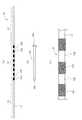
以下、本発明の実施の形態を添付図面を参照して説明する。図1は本発明の医療用鋸の実施例を示す図で、(a)は全体を示す図、(b)はガイドチューブの図、(c)は(a)の切削部の一部を拡大した図である。 Embodiments of the present invention will be described below with reference to the accompanying drawings. FIG. 1 is a view showing an embodiment of the medical saw of the present invention, (a) is a view showing the whole, (b) is a view of a guide tube, (c) is an enlarged view of a part of the cutting portion of (a). FIG.
本発明の医療用鋸10は、線条体11と、この線条体11の中間に形成された切削部12と、切削部12の両側の補助切削部13,13とから構成されている。 The
線条体11は、直径が1.0〜0.3mmφのステンレス鋼製のワイヤーを使用している。ステンレス鋼製とすることで、錆を防止し、錆による人体組織への悪影響を排除することができる。線条体11としては、骨の形状に沿って曲がれるように柔軟なものが望ましい。単線でも焼き鈍しをしたものであればよいが、撚線や編線が望ましい。撚線や編線を使用することで、柔軟性に富み、しかも強度の大きい線条体11を得ることができる。また、撚線や編線は表面に凹凸ができ、この凹凸により、小さい切削力ではあるが、血管や神経を損傷せずに骨を切削することが可能となる。撚線の撚り本数は、特に限定されないが、実施例では、7本×7本(合計49本)の撚り本数のものを使用している。 The
図示の実施例では、線条体11としてステンレス鋼製の撚線を使用したが、樹脂類やたとえば天然繊維や合成繊維の糸等を使用することもできる。この場合も、単線のフィラメントでも複数本のフィラメントを撚糸したものや、紡績糸でもよい。 In the illustrated embodiment, a stranded wire made of stainless steel is used as the
切削部12は、図1(c)に示すように、砥粒を固着した部分12aと固着しない部分12bとが交互に設けられた構成となっている。 As shown in FIG. 1C, the
砥粒としては、特に限定されないが、ダイヤモンドやCBN砥粒などの硬いものが望ましい。実施例では、ダイヤモンド砥粒の粒径が30〜40μmのものを使用している。また、線条体11に砥粒を固着する方法としては、接着剤でもよいが、人体への影響の少ないものを使用すべきである。また、骨を切削しているとき、砥粒が剥落することがあるので、できるだけ剥落が少なくなるように、強力な接着が望ましい。実施例では、ステンレス鋼素材の線条体11の表面に、一般医療用具で使用されているニッケル溶着を用いてダイヤモンドの砥粒を固着している。 The abrasive grains are not particularly limited, but hard ones such as diamond and CBN abrasive grains are desirable. In the examples, diamond abrasive grains having a particle size of 30 to 40 μm are used. In addition, as a method of fixing the abrasive grains to the
砥粒を固着した部分12aは、硬直化して柔軟性が失われるので、固着しない部分12bを交互に設け、柔軟性が確保できるようにしている。砥粒を固着した部分12aと固着しない部分12bとは等間隔に配置しなければならないということはないが、等間隔に配置すると、鋸10としての切削力が安定する。また、砥粒を固着した部分12aと固着しない部分12bとの長さは等しくしてもよいが、相違してもよい。実施例では、砥粒を固着した部分12aの長さと固着しない部分12bとの長さは等しく、2mmとしているが、1〜5mmの範囲が望ましい。1mm未満では、砥粒の付着が不十分となり、5mmを越えると、柔軟性が若干不足するからである。 Since the
切削部12の両端には、補助切削部13が形成されている。補助切削部13は、線条体11に何も加工をしていない部分である。線条体11が骨より硬い素材であり、かつ、その表面が撚線や編線なのでざらつきのある粗面となっており、線条体11そのものを往復摺動させることで、切削部12より切れ味は劣るが、骨を若干切削することができる。
本発明の医療用鋸10は、潤滑性のある素材でコーティングしている。潤滑剤としては、シリコーン樹脂やテフロン(登録商標)を使用することができる。コーティングすることで線条体11が直接生体に触れないこと、また、線条体11よりニッケルなどの有害物質の溶出を防ぐことができることから生体適合性が良くなる。また、切削部12に固着した砥粒が大きく、切れすぎてがたがたする場合にも、コーティングしてある場合はスムーズに切削することができる。コーティングする部分は、切削部12だけでもよいが、補助切削部13もコーティングしてよい。潤滑剤としては、潤滑性があればよいので、液体に限定されず、粉状体でもよい。 The
図1(b)はガイドチューブ20の図である。ガイドチューブ20は合成樹脂製の柔軟な中空の筒状体で、入口20aがラッパ状に広がり、出口20bには鋸10が通過できる孔が貫通している。 FIG. 1B is a view of the
治療対象となる骨の骨と生体組織との間の隙間に鋸10の一端を挿入し、骨の反対側から引き出して、鋸10の両端を交互に引くことで切削をするのであるが、骨と生体組織との間の隙間は狭く、直接鋸10を通すと、生体組織を損傷させるおそれがある。そこで、最初にこのガイドチューブ20を通しておいて、このガイドチューブ20に鋸10を通すことで、生体組織を損傷させることなく安全に骨の一方から反対側へと鋸10を通すことができるようにするのである。 One end of the
図2は、本発明の医療用鋸10で、脊椎30の切開をする様子を示す斜視図である。補助切削部13は、そのままの状態で、手で掴んで交互に鋸10を引くことができるが、通常は、鋸10の両端部に取手15を取り付けて使用する。切削する脊椎30は1つでもよいが、この図に示すように、複数の脊椎30を跨いで本発明の医療用鋸10を通し、これら複数の脊椎30を一度に切削することも可能である。 FIG. 2 is a perspective view showing a state where the
脊椎30の内部には、生体組織として硬膜に覆われた脊髄31が通っており、切削や切断の際にこれを損傷させないようにする必要がある。そこで、図3により本発明の医療用鋸10の使用の仕方を説明する。 Inside the
図3には模式化した脊椎30を示す。脊椎30は、環状であるが、説明のためその一部を切り欠いて図示している。脊椎30の内部には生体組織としての脊髄31が通過している。 FIG. 3 shows a
鋸10を脊椎30内に挿入するのに先だって、まず、図3(a)に示すように、ガイドチューブ20の出口20b側(先端側)を治療対象となる脊椎30の一方側から矢印に示すように挿入し、ガイドチューブ20の先端側を脊椎30の反対側から突出させる。 Prior to inserting the
次に、図3(b)に示すように、ガイドチューブ20の入口20aから鋸10の一端を挿入する。鋸10はガイドチューブ20の中空部を通過し、先端へと向かう。 Next, as shown in FIG. 3B, one end of the
図3(c)に示すように、鋸10の先端部がガイドチューブ20の出口から突出したら、これを鉗子で掴み、引き出す。鋸10を引き出したら、図3(d)に示すように、ガイドチューブ20を引き出して取り除く。 As shown in FIG. 3C, when the tip of the
ガイドチューブ20の入口20aは、図1(b)に示すようにラッパ状に開いているので、ガイドチューブ20を出し入れするとき、この部分が脊椎30と脊髄31との間を通らない方向に出し入れするとよい。こうすることによって、脊髄31の損傷を防止することができる。 Since the
その後、図3(e)に示すように、鋸10の両端を交互に引いて切断する。ただし、脊椎30の周囲に血管や神経などの軟部組織がある場合は、最初に補助切削部13で脊椎30の骨を少し切除して骨に鋸10を食い込ませた後、切削部12で脊椎30の所望の部位を切断するとよい。補助切削部13は切削力が小さいので、血管や神経を切断することがなく、これらを押し動かして切削位置から外れる位置に移動させる。その後、切削部12で切断すれば、補助切削部13により形成(切除)したスペースを切削部12が通過するため、血管や神経を損傷することを防止することができる。 Thereafter, as shown in FIG. 3E, both ends of the
図3の説明では、ガイドチューブ20を患部に通してから鋸10をガイドチューブに挿入したが、予めガイドチューブ20に鋸10を挿入してから、患部に通してもよい。 In the description of FIG. 3, the
〔切断試験〕
本発明の医療用鋸と、ステンレス鋼製の撚線からなる医療用鋸とで切断試験を行った。切断する試料としては、骨に近い性質のエポキシ樹脂製の直径12mmの丸棒を使用し、この丸棒を切断するのに鋸を何回往復させたかを比較した。[Cutting test]
A cutting test was performed with the medical saw of the present invention and a medical saw made of stainless steel stranded wire. As a sample to be cut, a round bar made of an epoxy resin having a property similar to that of a bone was used, and the number of times the saw was reciprocated to cut the round bar was compared.
本発明の医療用鋸は、切削部12の長さが200mm、補助切削部13の長さが片側300mmずつで合計800mmであった。砥粒は30〜40μmのダイヤモンド砥粒を使用し、砥粒を固着した長さと固着しない長さは共に2mmのピッチとした。比較対象としての砥粒を付けないステンレス鋼製の撚線からなる医療用鋸は、全長が800mmである。撚線は双方とも同じものを使用している。また、双方とも、実際の使用時に近い荷重として800gの錘を両端に吊り下げ、往復動させた。本発明の医療用鋸では、400回前後の往復動で切断できたが、砥粒のない比較例のものでは3000回往復させても切断できなかった。 In the medical saw of the present invention, the length of the cutting
なお、これまで線条体11に砥粒を固着した例を中心に説明したが、これに限定するものではなく、例えば、図4に示すように線条体の形状を加工することで切削部を形成するようにしてもよい。この例の医療用鋸100では、ステンレス鋼などの金属製単線からなる線条体110の中間に等間隔で多数の溝121を設けた切削部120を形成し、その両側に角度の緩い溝131を形成した補助切削部130を形成している。切削部120の溝はほぼ直角で角が切り立っているため良く切れる。これに対し、補助切削部130の溝は角度が緩いため、あまり切れないので、血管や神経を損傷させないで骨を切削することができる。 In addition, although it demonstrated centering on the example which fixed the abrasive grain to the
10,100 医療用鋸
11,110 線条体
12,120 切削部
12a 砥粒を固着した部分
12b 砥粒を固着しない部分
13,130補助切削部
30脊椎DESCRIPTION OF SYMBOLS 10,100 Medical saw 11,110 Striated body 12,120 Cutting
Claims (3)
Translated fromJapanesePriority Applications (2)
| Application Number | Priority Date | Filing Date | Title |
|---|---|---|---|
| JP2005137155AJP4493547B2 (en) | 2005-05-10 | 2005-05-10 | Medical saw |
| US11/430,823US8137353B2 (en) | 2005-05-10 | 2006-05-10 | Surgical saw |
Applications Claiming Priority (1)
| Application Number | Priority Date | Filing Date | Title |
|---|---|---|---|
| JP2005137155AJP4493547B2 (en) | 2005-05-10 | 2005-05-10 | Medical saw |
Publications (2)
| Publication Number | Publication Date |
|---|---|
| JP2006314367A JP2006314367A (en) | 2006-11-24 |
| JP4493547B2true JP4493547B2 (en) | 2010-06-30 |
Family
ID=37535591
Family Applications (1)
| Application Number | Title | Priority Date | Filing Date |
|---|---|---|---|
| JP2005137155AExpired - LifetimeJP4493547B2 (en) | 2005-05-10 | 2005-05-10 | Medical saw |
Country Status (2)
| Country | Link |
|---|---|
| US (1) | US8137353B2 (en) |
| JP (1) | JP4493547B2 (en) |
Families Citing this family (48)
| Publication number | Priority date | Publication date | Assignee | Title |
|---|---|---|---|---|
| US8613745B2 (en) | 2004-10-15 | 2013-12-24 | Baxano Surgical, Inc. | Methods, systems and devices for carpal tunnel release |
| US8221397B2 (en) | 2004-10-15 | 2012-07-17 | Baxano, Inc. | Devices and methods for tissue modification |
| US20090171381A1 (en)* | 2007-12-28 | 2009-07-02 | Schmitz Gregory P | Devices, methods and systems for neural localization |
| US8430881B2 (en) | 2004-10-15 | 2013-04-30 | Baxano, Inc. | Mechanical tissue modification devices and methods |
| US7963915B2 (en)* | 2004-10-15 | 2011-06-21 | Baxano, Inc. | Devices and methods for tissue access |
| US20110190772A1 (en) | 2004-10-15 | 2011-08-04 | Vahid Saadat | Powered tissue modification devices and methods |
| JP5243034B2 (en) | 2004-10-15 | 2013-07-24 | バクサノ,インク. | Tissue removal device |
| US9247952B2 (en) | 2004-10-15 | 2016-02-02 | Amendia, Inc. | Devices and methods for tissue access |
| US7857813B2 (en) | 2006-08-29 | 2010-12-28 | Baxano, Inc. | Tissue access guidewire system and method |
| US9101386B2 (en) | 2004-10-15 | 2015-08-11 | Amendia, Inc. | Devices and methods for treating tissue |
| US7578819B2 (en) | 2005-05-16 | 2009-08-25 | Baxano, Inc. | Spinal access and neural localization |
| US20100331883A1 (en) | 2004-10-15 | 2010-12-30 | Schmitz Gregory P | Access and tissue modification systems and methods |
| US8048080B2 (en) | 2004-10-15 | 2011-11-01 | Baxano, Inc. | Flexible tissue rasp |
| US8062300B2 (en) | 2006-05-04 | 2011-11-22 | Baxano, Inc. | Tissue removal with at least partially flexible devices |
| US8257356B2 (en) | 2004-10-15 | 2012-09-04 | Baxano, Inc. | Guidewire exchange systems to treat spinal stenosis |
| US7887538B2 (en) | 2005-10-15 | 2011-02-15 | Baxano, Inc. | Methods and apparatus for tissue modification |
| US7938830B2 (en) | 2004-10-15 | 2011-05-10 | Baxano, Inc. | Powered tissue modification devices and methods |
| US7959577B2 (en) | 2007-09-06 | 2011-06-14 | Baxano, Inc. | Method, system, and apparatus for neural localization |
| US8092456B2 (en) | 2005-10-15 | 2012-01-10 | Baxano, Inc. | Multiple pathways for spinal nerve root decompression from a single access point |
| US8062298B2 (en) | 2005-10-15 | 2011-11-22 | Baxano, Inc. | Flexible tissue removal devices and methods |
| US8366712B2 (en) | 2005-10-15 | 2013-02-05 | Baxano, Inc. | Multiple pathways for spinal nerve root decompression from a single access point |
| US20080033465A1 (en)* | 2006-08-01 | 2008-02-07 | Baxano, Inc. | Multi-Wire Tissue Cutter |
| US8828000B2 (en)* | 2007-02-13 | 2014-09-09 | The Board Of Regents Of The University Of Texas System | Apparatus to trace and cut a tendon or other laterally extended anatomical structure |
| US8192436B2 (en) | 2007-12-07 | 2012-06-05 | Baxano, Inc. | Tissue modification devices |
| US8409206B2 (en) | 2008-07-01 | 2013-04-02 | Baxano, Inc. | Tissue modification devices and methods |
| US9314253B2 (en) | 2008-07-01 | 2016-04-19 | Amendia, Inc. | Tissue modification devices and methods |
| US8398641B2 (en) | 2008-07-01 | 2013-03-19 | Baxano, Inc. | Tissue modification devices and methods |
| AU2009271047B2 (en) | 2008-07-14 | 2014-04-17 | Baxano Surgical, Inc. | Tissue modification devices |
| US9161773B2 (en)* | 2008-12-23 | 2015-10-20 | Benvenue Medical, Inc. | Tissue removal tools and methods of use |
| EP2405823A4 (en) | 2009-03-13 | 2012-07-04 | Baxano Inc | Flexible neural localization devices and methods |
| US8394102B2 (en) | 2009-06-25 | 2013-03-12 | Baxano, Inc. | Surgical tools for treatment of spinal stenosis |
| WO2011017665A2 (en) | 2009-08-07 | 2011-02-10 | Thayer Intellectual Property, Inc. | Systems and methods for treatment of compressed nerves |
| US8753364B2 (en) | 2009-08-07 | 2014-06-17 | Thayer Intellectual Property, Inc. | Systems and methods for treatment of compressed nerves |
| US8652157B2 (en) | 2009-08-07 | 2014-02-18 | Thayer Intellectual Property, Inc. | Systems and methods for treatment of compressed nerves |
| WO2011140206A1 (en)* | 2010-05-04 | 2011-11-10 | The Ohio State University | Surgical device, method of performing surgery using same, and surgical device kit |
| USD674489S1 (en) | 2010-09-15 | 2013-01-15 | Thayer Intellectual Property, Inc. | Handle for a medical device |
| USD666725S1 (en) | 2010-09-15 | 2012-09-04 | Thayer Intellectual Property, Inc. | Handle for a medical device |
| USD673683S1 (en) | 2010-09-15 | 2013-01-01 | Thayer Intellectual Property, Inc. | Medical device |
| US8858559B2 (en) | 2012-02-06 | 2014-10-14 | Medtronic Ps Medical, Inc. | Saw blade stability and collet system mechanism |
| US8696677B2 (en) | 2012-02-13 | 2014-04-15 | DePuy Synthes Products, LLC | Orthopaedic surgical saw assembly for removing an implanted glenoid component and method of using the same |
| WO2013179384A1 (en)* | 2012-05-29 | 2013-12-05 | 株式会社東京ワイヤー製作所 | Wire saw |
| US9480574B2 (en) | 2013-03-14 | 2016-11-01 | Benvenue Medical, Inc. | Spinal fusion implants and devices and methods for deploying such implants |
| US10314605B2 (en) | 2014-07-08 | 2019-06-11 | Benvenue Medical, Inc. | Apparatus and methods for disrupting intervertebral disc tissue |
| US10022243B2 (en) | 2015-02-06 | 2018-07-17 | Benvenue Medical, Inc. | Graft material injector system and method |
| US10758286B2 (en) | 2017-03-22 | 2020-09-01 | Benvenue Medical, Inc. | Minimal impact access system to disc space |
| WO2019148083A1 (en) | 2018-01-29 | 2019-08-01 | Benvenue Medical, Inc. | Minimally invasive interbody fusion |
| WO2019178575A1 (en) | 2018-03-16 | 2019-09-19 | Benvenue Medical, Inc. | Articulated instrumentation and methods of using the same |
| CN111938833B (en)* | 2020-08-18 | 2022-02-15 | 北京大学第三医院(北京大学第三临床医学院) | Intraoperative spinal cord protection device |
Family Cites Families (24)
| Publication number | Priority date | Publication date | Assignee | Title |
|---|---|---|---|---|
| US184804A (en)* | 1876-11-28 | Improvement in surgical saws | ||
| US1306636A (en)* | 1918-06-18 | 1919-06-10 | George May Selby | Abrasive wire rope. |
| US2752964A (en)* | 1953-04-15 | 1956-07-03 | Prusinski Stanley | Flexible hand saw |
| US3150470A (en)* | 1961-08-11 | 1964-09-29 | Lee H Barron | Diamond coated wire saw |
| US4258763A (en)* | 1978-11-20 | 1981-03-31 | Fernando Figueredo | Cutting device having a flexible cutting element |
| US4464836A (en)* | 1982-09-15 | 1984-08-14 | Hissa Robert E | Friction saw and handle assembly |
| US4709699A (en)* | 1986-08-06 | 1987-12-01 | Fort Wayne Metals Research Products Corporation | Surgeon's Gigli saw and method |
| JPH041929Y2 (en)* | 1987-09-03 | 1992-01-23 | ||
| JPH0286510U (en)* | 1988-12-21 | 1990-07-09 | ||
| JPH0318201A (en) | 1989-06-15 | 1991-01-25 | Fuji Electric Co Ltd | Collector head of pantograph |
| JPH04244380A (en)* | 1991-01-29 | 1992-09-01 | Toyoda Mach Works Ltd | Manufacture for electrodeposited grinding wheel |
| JP3018201U (en) | 1994-12-13 | 1995-11-14 | 三谷産業株式会社 | Medical sawing tool |
| JPH1053789A (en)* | 1996-08-12 | 1998-02-24 | Nippei Toyama Corp | Water-base working fluid composition for wire cutter |
| US6152894A (en)* | 1997-10-27 | 2000-11-28 | Kubler; Harald | Surgical cutting instrument |
| US6063083A (en)* | 1998-05-22 | 2000-05-16 | Duong-Van; Minh | Electrosurgery blade having discrete point discharge saw-tooth edge |
| JP3526781B2 (en)* | 1999-04-15 | 2004-05-17 | 株式会社ノリタケスーパーアブレーシブ | Resin bond wire saw |
| JP2002254327A (en)* | 2001-03-02 | 2002-09-10 | Ngk Insulators Ltd | Saw wire for wire saw and machining method using the same |
| JP3975320B2 (en)* | 2001-04-13 | 2007-09-12 | ニプロ株式会社 | Hole forming pin for indwelling needle insertion |
| JP2004017276A (en)* | 2002-06-17 | 2004-01-22 | Tadao Ishikawa | Wire saw and its manufacturing method |
| US20030224705A1 (en)* | 2003-02-21 | 2003-12-04 | Schmidt James E. | Diamond abrasive tonehole file for woodwind musical instruments |
| JP2004291121A (en)* | 2003-03-26 | 2004-10-21 | Noritake Super Abrasive:Kk | Super abrasive grain fret-saw blade |
| US7846165B2 (en)* | 2004-03-29 | 2010-12-07 | Depuy Products, Inc. | Method and apparatus for arthroscopic bone preparation |
| US7963915B2 (en)* | 2004-10-15 | 2011-06-21 | Baxano, Inc. | Devices and methods for tissue access |
| US20080255624A1 (en)* | 2007-03-30 | 2008-10-16 | Gregory Arcenio | Methods and devices for multipoint access of a body part |
- 2005
- 2005-05-10JPJP2005137155Apatent/JP4493547B2/ennot_activeExpired - Lifetime
- 2006
- 2006-05-10USUS11/430,823patent/US8137353B2/enactiveActive
Also Published As
| Publication number | Publication date |
|---|---|
| JP2006314367A (en) | 2006-11-24 |
| US20070055262A1 (en) | 2007-03-08 |
| US8137353B2 (en) | 2012-03-20 |
Similar Documents
| Publication | Publication Date | Title |
|---|---|---|
| JP4493547B2 (en) | Medical saw | |
| EP2427124B1 (en) | Surgical instrument for tensioning and securing a flexible suture | |
| CA2132370C (en) | Surgical cable | |
| JP4526075B2 (en) | Surgical cobra head suture needle | |
| CN103702626B (en) | Flexible Shaft Surgical Instruments | |
| JP6906529B2 (en) | Braided or braided tubular metal construct | |
| WO2005096976B1 (en) | Flexible nail assembly for fractures of long bones | |
| US20110245875A1 (en) | Sublaminar wired screwed device for spinal fusion | |
| JPH03244445A (en) | medical suture needle | |
| JPH07204207A (en) | High modulus material for surgical needle | |
| JP2006288864A (en) | Bone fixture for surgical operation | |
| JP2009279427A (en) | Sharp-pointed needle | |
| US8512373B2 (en) | Suture device | |
| JP2016521617A (en) | Dental nerve treatment end file | |
| WO1996020645A1 (en) | Tissue removing device | |
| DE10146011A1 (en) | Method for destruction of a thrombus in a blood vessel by use of ultrasonic vibrations transmitted to a vibration head via an ultrasonic wave-guide from a generator | |
| US9814479B2 (en) | Cartilage holding forceps | |
| Scheiner et al. | A study of the fatigue properties of small diameter wires used in intramuscular electrodes | |
| JP2005532873A (en) | Surgical SE suture needle | |
| JPH07102B2 (en) | Spinal fixation thread | |
| JP5916138B2 (en) | Surgical cable and manufacturing method thereof | |
| DE102018009476B3 (en) | Excisionsskalpell | |
| KR20210037871A (en) | Rod for fixing the spine | |
| JP2008017955A (en) | Osteotomy wire and wire guide tube used therefor | |
| DE102009030512A1 (en) | Apparatus for posterior stabilization of thoracolumbar spine, has abrasion resistant material layer provided in clamping area of clamping screw and carbon-composite rod |
Legal Events
| Date | Code | Title | Description |
|---|---|---|---|
| A621 | Written request for application examination | Free format text:JAPANESE INTERMEDIATE CODE: A621 Effective date:20080418 | |
| A977 | Report on retrieval | Free format text:JAPANESE INTERMEDIATE CODE: A971007 Effective date:20090826 | |
| A131 | Notification of reasons for refusal | Free format text:JAPANESE INTERMEDIATE CODE: A131 Effective date:20090901 | |
| A521 | Request for written amendment filed | Free format text:JAPANESE INTERMEDIATE CODE: A523 Effective date:20091027 | |
| TRDD | Decision of grant or rejection written | ||
| A01 | Written decision to grant a patent or to grant a registration (utility model) | Free format text:JAPANESE INTERMEDIATE CODE: A01 Effective date:20100316 | |
| A01 | Written decision to grant a patent or to grant a registration (utility model) | Free format text:JAPANESE INTERMEDIATE CODE: A01 | |
| A61 | First payment of annual fees (during grant procedure) | Free format text:JAPANESE INTERMEDIATE CODE: A61 Effective date:20100406 | |
| R150 | Certificate of patent or registration of utility model | Ref document number:4493547 Country of ref document:JP Free format text:JAPANESE INTERMEDIATE CODE: R150 Free format text:JAPANESE INTERMEDIATE CODE: R150 | |
| FPAY | Renewal fee payment (event date is renewal date of database) | Free format text:PAYMENT UNTIL: 20130416 Year of fee payment:3 | |
| FPAY | Renewal fee payment (event date is renewal date of database) | Free format text:PAYMENT UNTIL: 20130416 Year of fee payment:3 | |
| FPAY | Renewal fee payment (event date is renewal date of database) | Free format text:PAYMENT UNTIL: 20140416 Year of fee payment:4 | |
| R250 | Receipt of annual fees | Free format text:JAPANESE INTERMEDIATE CODE: R250 | |
| R250 | Receipt of annual fees | Free format text:JAPANESE INTERMEDIATE CODE: R250 | |
| R250 | Receipt of annual fees | Free format text:JAPANESE INTERMEDIATE CODE: R250 | |
| R250 | Receipt of annual fees | Free format text:JAPANESE INTERMEDIATE CODE: R250 | |
| R250 | Receipt of annual fees | Free format text:JAPANESE INTERMEDIATE CODE: R250 | |
| R250 | Receipt of annual fees | Free format text:JAPANESE INTERMEDIATE CODE: R250 | |
| R250 | Receipt of annual fees | Free format text:JAPANESE INTERMEDIATE CODE: R250 | |
| R250 | Receipt of annual fees | Free format text:JAPANESE INTERMEDIATE CODE: R250 | |
| R250 | Receipt of annual fees | Free format text:JAPANESE INTERMEDIATE CODE: R250 | |
| R250 | Receipt of annual fees | Free format text:JAPANESE INTERMEDIATE CODE: R250 | |
| R250 | Receipt of annual fees | Free format text:JAPANESE INTERMEDIATE CODE: R250 | |
| R250 | Receipt of annual fees | Free format text:JAPANESE INTERMEDIATE CODE: R250 |