JP4492481B2 - Camera housing - Google Patents
Camera housingDownload PDFInfo
- Publication number
- JP4492481B2 JP4492481B2JP2005236051AJP2005236051AJP4492481B2JP 4492481 B2JP4492481 B2JP 4492481B2JP 2005236051 AJP2005236051 AJP 2005236051AJP 2005236051 AJP2005236051 AJP 2005236051AJP 4492481 B2JP4492481 B2JP 4492481B2
- Authority
- JP
- Japan
- Prior art keywords
- camera housing
- touch panel
- contact member
- camera
- torsion spring
- Prior art date
- Legal status (The legal status is an assumption and is not a legal conclusion. Google has not performed a legal analysis and makes no representation as to the accuracy of the status listed.)
- Expired - Lifetime
Links
Images


Classifications
- G—PHYSICS
- G03—PHOTOGRAPHY; CINEMATOGRAPHY; ANALOGOUS TECHNIQUES USING WAVES OTHER THAN OPTICAL WAVES; ELECTROGRAPHY; HOLOGRAPHY
- G03B—APPARATUS OR ARRANGEMENTS FOR TAKING PHOTOGRAPHS OR FOR PROJECTING OR VIEWING THEM; APPARATUS OR ARRANGEMENTS EMPLOYING ANALOGOUS TECHNIQUES USING WAVES OTHER THAN OPTICAL WAVES; ACCESSORIES THEREFOR
- G03B17/00—Details of cameras or camera bodies; Accessories therefor
- G03B17/02—Bodies
- G03B17/08—Waterproof bodies or housings
Landscapes
- Physics & Mathematics (AREA)
- General Physics & Mathematics (AREA)
- Camera Bodies And Camera Details Or Accessories (AREA)
- Structure And Mechanism Of Cameras (AREA)
- Studio Devices (AREA)
- Accessories Of Cameras (AREA)
Description
Translated fromJapanese本発明は、デジタルカメラやビデオカメラを収納して水中撮影等を行うためのカメラハウジングに関する。 The present invention relates to a camera housing for housing a digital camera or a video camera and performing underwater photography or the like.
近年、デジタルカメラやビデオカメラでは、液晶モニタの大型化とカメラ全体の小型化とに伴い、操作ボタン等を配置するためのスペースが減少している。このため、解決策としてタッチパネル付きの液晶モニタを備えたカメラが提案されており、さらに、斯かるカメラを収納するためのカメラハウジングも提案されている(例えば、特許文献1を参照。)。
しかしながら、上記特許文献1に開示されているカメラハウジングは、カメラを収納した際に該カメラの液晶モニタに対向する部分が入力パネルとして柔軟な材質の部材で構成されており、この柔軟な入力パネルを直接押し込んでタッチパネルに当接させることでタッチパネルの操作を行う構成である。このため、入力パネルが強い力で押し込まれるとタッチパネルを破損させてしまうという問題があり、また、水深が大きく入力パネルに水圧が加わるような水中での使用には適していなかった。 However, in the camera housing disclosed in Patent Document 1, the portion of the camera that faces the liquid crystal monitor when the camera is housed is formed of a flexible material as an input panel. It is the structure which operates a touch panel by pushing in directly and making it contact | abut on a touch panel. For this reason, when the input panel is pushed in with a strong force, there is a problem that the touch panel is damaged, and it is not suitable for use in water where the water depth is large and water pressure is applied to the input panel.
そこで本発明は上記問題点に鑑みてなされたものであり、タッチパネル付きの液晶モニタを備えたカメラの収納に適し、タッチパネルの破損を防ぐカメラハウジングを提供することを目的とする。 Accordingly, the present invention has been made in view of the above problems, and an object thereof is to provide a camera housing that is suitable for housing a camera having a liquid crystal monitor with a touch panel and prevents damage to the touch panel.
上記課題を解決するために第1の発明は、
タッチパネル付きの表示部を備えたカメラを収納するためのカメラハウジングであって、
前記カメラハウジング外部に設けられている外部操作部と、
前記カメラハウジング内部に設けられており前記タッチパネルに接触して当該タッチパネルを操作するための接触部材と、
前記外部操作部と前記接触部材との間に配置されており、前記外部操作部に加えられた押圧力を前記接触部材へ伝達するねじりバネと、を有し、
前記ねじりバネは、前記接触部材へ伝達する前記押圧力を制限し、
前記外部操作部及び前記ねじりバネは、前記カメラハウジングに前記カメラを収納したときに、前記カメラハウジングにおける前記表示部に対向する部分から外れた位置に設けられていることを特徴とするカメラハウジングを提供する。In order to solve the above problems,the first invention
A camera housing for storing a camera having a display unit with a touch panel,
An external operation unit provided outside the camera housing;
A contact member provided inside the camera housing for operating the touch panel in contact with the touch panel;
A torsion spring that is disposed between the external operation unit and the contact member, and that transmits a pressing force applied to the external operation unit to the contact member;
The torsion spring restricts the pressing force transmitted to the contact member;
The camera housing characterized in that the external operation section and the torsion spring are provided at positions separated from a portion of the camera housing facing the display section when the camera is housed in the camera housing. provide.
また第2の発明は、Also, the second invention is
タッチパネル付きの表示部を備えたカメラを収納するためのカメラハウジングであって、A camera housing for storing a camera having a display unit with a touch panel,
前記カメラハウジング外部に設けられている外部操作部と、An external operation unit provided outside the camera housing;
前記カメラハウジング内部に設けられており前記タッチパネルに接触して当該タッチパネルを操作するための接触部材と、A contact member provided inside the camera housing for operating the touch panel in contact with the touch panel;
前記外部操作部と前記接触部材との間に配置されており、前記外部操作部に加えられた押圧力を前記接触部材へ伝達するねじりバネと、を有し、A torsion spring that is disposed between the external operation unit and the contact member, and transmits a pressing force applied to the external operation unit to the contact member;
前記ねじりバネは、前記接触部材へ伝達する前記押圧力を制限し、The torsion spring limits the pressing force transmitted to the contact member,
前記接触部材は、前記表示部と重ならない部分に光の拡散面を有することを特徴とするカメラハウジングを提供する。The contact member may have a light diffusing surface at a portion that does not overlap the display unit.
また第1の発明のカメラハウジングは、
前記接触部材は、前記表示部と重ならない部分に光の拡散面を有することを特徴とする。
また第1及び第2の発明のカメラハウジングは、
前記外部操作部が操作されたときに、前記外部操作部の他端に当接し、前記押圧力を前記ねじりバネに伝達する押圧力伝達部材をさらに有し、
前記押圧力伝達部材と、前記ねじりバネは同一の回転軸に回動可能に支持されることを特徴とする。The camera housing ofthe first invention is
The contact member has a light diffusing surface in a portion that does not overlap the display portion .
The camera housings ofthe first and second inventions
A pressing force transmission member that contacts the other end of the external operation unit when the external operation unit is operated and transmits the pressing force to the torsion spring;
The pressing force transmitting member and the torsion spring are rotatably supported on the same rotating shaft .
本発明によれば、タッチパネル付きの液晶モニタを備えたカメラの収納に適し、タッチパネルの破損を防ぐカメラハウジングを提供することができる。 ADVANTAGE OF THE INVENTION According to this invention, it is suitable for accommodation of the camera provided with the liquid crystal monitor with a touch panel, and can provide the camera housing which prevents damage to a touch panel.
以下、本発明の実施形態に係るカメラハウジングを添付図面に基づいて詳細に説明する。
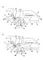
図1は、本発明の実施形態に係るカメラハウジングの外観を示す図である。
本実施形態に係るカメラハウジング1は、タッチパネル付きの液晶モニタを備えたカメラを収納することに適したカメラハウジングであって、図1に示すように前カバー2と後カバー3とからなり、ヒンジ部4を介して開閉自在に接続されている。そして、前カバー2と後カバー3は、透明な素材で構成されている。なお、図1には本ハウジング1がタッチパネル5,6,7付きの液晶モニタ8を備えた後述のデジタルカメラ9を収納している様子が示されている。Hereinafter, a camera housing according to an embodiment of the present invention will be described in detail with reference to the accompanying drawings.
FIG. 1 is a view showing an appearance of a camera housing according to an embodiment of the present invention.
A camera housing 1 according to the present embodiment is a camera housing suitable for housing a camera having a liquid crystal monitor with a touch panel, and includes a
前カバー2の前面には、上面には電源ボタン10及びシャッタボタン11がそれぞれ備えられており、使用者はこの電源ボタン10及びシャッタボタン11を介してデジタルカメラ9の電源ボタン及びシャッタボタンを操作することができる。
後カバー3の背面には、デジタルカメラ9の液晶モニタ8をハウジング1外部から視認するための液晶モニタ用窓12と、液晶モニタ8のタッチパネル5,6,7を操作するための後に詳述する操作ボタン13,14,15とを備えている。なお、液晶モニタ用窓12は、透明な素材で構成されており、デジタルカメラ9の液晶モニタ8の大きさと位置に対応して設けられている。On the front surface of the
On the rear surface of the
また、後カバー3における前カバー2との当接面、詳細には後述する図4に示すように後カバー3における前カバー2側端部外周には、シールゴム16が全周にわたってはめ込まれている。これにより、デジタルカメラ9を収納して前カバー2と後カバー3とをバックル17で締め付け固定することで、本ハウジング1は密閉されて防水が達成される。以上の構成により、本ハウジング1に収納したデジタルカメラ9の水中での使用が可能となる。 Further, a
図2及び図3は、本発明の実施形態に係るカメラハウジングに収納されるデジタルカメラの外観を示す図である。
図2及び図3に示すデジタルカメラ9は、それ自体で地上での使用が可能な一般的なデジタルカメラであって、前面にレンズ18、上面に電源ボタン19及びシャッタボタン20、背面にはタッチパネル5,6,7付きの液晶モニタ8を備えている。2 and 3 are views showing the external appearance of a digital camera housed in the camera housing according to the embodiment of the present invention.
The
なお、図3はまた、使用者によってタッチパネル5,6,7が操作された際のアイコン表示の変化の様子の一例を示している。
液晶モニタ8のモニタ面左側にはタッチパネル5,6,7が設けられており、デジタルカメラ9の電源を入れた直後、この液晶モニタ8には図3(a)に示すようにタッチパネル5,6,7に対応して「静止画撮影」、「動画撮影」、「再生」と表示され、使用モードの選択が促される。ここで、タッチパネル5によって「静止画撮影」を選択すれば、図3(b)に示すようにタッチパネル5,6,7に対応して「オート」、「シーン」、「戻る」と表示され、撮影モードの選択が促される。さらに、タッチパネル5によって「オート」を選択すれば、図3(c)に示すようにタッチパネル5,6,7に対応して「↓(フラッシュマーク)」、「MENU」、「戻る」と表示される。ここで使用者は、シャッタボタン20を押せば撮影ができ、「↓(フラッシュマーク)」を選択すればフラッシュの設定(発光禁止等)を変更することができる。また、「MENU」を選択すれば撮影に関する各種の詳細な設定を行うための表示に切り替わり、「戻る」を選択すれば1つ前の画面が再び表示される。FIG. 3 also shows an example of how the icon display changes when the
斯かる構成のデジタルカメラ9を収納する本カメラハウジング1の最も特徴的な構成である操作ボタン13,14,15について以下に説明する。
図4、図5、及び図6は、本発明の実施形態に係るカメラハウジングにおける操作ボタンの構成を示す図である。なお詳細には、図4及び図5は図1におけるA−A断面付近の要部拡大図であり、図6は図4におけるB−B断面付近の要部拡大図である。The
4, 5, and 6 are diagrams showing the configuration of the operation buttons in the camera housing according to the embodiment of the present invention. In detail, FIGS. 4 and 5 are enlarged views of the main part in the vicinity of the AA cross section in FIG. 1, and FIG. 6 is an enlarged view of the main part in the vicinity of the BB cross section in FIG.
図4に示すように操作ボタン14は、使用者によって押し込まれた際にその軸14aの先端が、後述の上側部材21の突起部21aに当接して該上側部材21を内側へ押し込むことができるように後カバー3に挿設されており、バネ14bによって外側即ち図4中下方向へ付勢されている。なお、操作ボタン14の軸14aと後カバー3との間にはOリング14cが備えられており、水密に保たれている。
後カバー3の内側の角付近には、上方へ向かって延在する軸22が設けられており、この軸22は図6に示すように上から順に、ねじりバネ23、上側部材21、ねじりバネ24、下側部材25をそれぞれ回動可能に支持している。As shown in FIG. 4, when the
A
上側部材21は、軸22から水平方向へ延在する細長い板状部材であって、その上側には上述した操作ボタン14の軸14a先端が当接する突起部21aが一体的に形成されており、さらにその下側にも突起部21bが一体的に形成されている。
そして、ねじりバネ23の一方の腕は後カバー3の内壁3aに当接し、かつもう一方の腕は上側部材21の突起部21aに当接しており、これにより上側部材21は突起部21aを介して時計回り方向へ付勢され、後カバー3の内壁3bに押し付けられている。The
One arm of the
また、下側部材25は、軸22から水平方向へ上側部材21よりも長く延在しさらに先端部分が上側に折れ曲がったL字型の板状部材であって、該下側部材25の上側には突起部25aが一体的に形成されており、さらに上側に折れ曲がった部分の先端には後述する接触部材26が一体的に形成されている。
そして、上側部材21の突起部21bと下側部材25の突起部25aとは、ねじりバネ24の2本の腕の間に配置されており、これにより突起部21bと突起部25aとは2本の腕によって両側から挟み込むように付勢されて上側部材21と下側部材25の相対位置が固定されている。Further, the
The protruding
接触部材26は、デジタルカメラ9の液晶モニタ8に備えられたタッチパネル6に接触して当該タッチパネル6を操作するものであって、タッチパネル6に直接接触する先端部分が上方から見て液晶パネル8側に傾けて形成されている。そして上述のように、上側部材21と下側部材25はねじりバネ24によって相対位置が固定され、さらに上側部材21はねじりバネ23によって時計回り方向へ付勢されているため、下側部材25も上側部材21とともに時計回り方向へ付勢されて、接触部材26がタッチパネル6に接触しないように保たれている。 The
また、斯かる接触部材26は全体が透明樹脂(本実施形態においてはポリカーボネート)で構成されており、これにより液晶モニタ8の表示を遮ぎることがない。
また、さらに接触部材26は、後カバー3側の側面の一部、詳細には接触部材26における後カバー3側の側面のうちで液晶モニタ8と重ならない部分(図1及び図6における斜線部分)が、シボ等の拡散面で構成されている。これにより、液晶パネル8からの光の一部が接触部材26内を進行して拡散面から射出されることとなり、すなわち使用者はハウジング1における操作ボタン14とタッチパネル6との間の部分が光って見えるようになる。したがって使用者は、操作ボタン14とタッチパネル6との位置関係を把握しやすくなり、このことは操作ボタンの数が多いときにより有効となる。Further, the
Further, the
以上の構成の下、使用者によって操作ボタン14が押し込まれると、操作ボタン14の軸14a先端が上側部材21の突起部21aに当接して押し込む力が加えられ、該上側部材21は軸22を中心に内側へ回動する。このとき下側部材25は、ねじりバネ24によって上側部材21に固定されているため、図5(b)に示すように上側部材21とともに内側へ回動する。これにより下側部材25における接触部材26はタッチパネル6に接触してタッチパネル操作が達成される。なお、タッチパネル操作後、使用者が操作ボタン14を離すと、ねじりバネ23、ねじりバネ24、及びバネ14bによって各部材が付勢され、操作ボタン14が押し込まれる前の状態(図4(a)に示されている状態)に戻る。 Under the above configuration, when the
以上のように、操作ボタン14に加えられた押圧力をねじりバネ24を介して接触部材26へ伝達し該接触部材26をタッチパネル6に直接接触させて、操作ボタン14によるタッチパネル6の操作を実現することができる。 As described above, the pressing force applied to the
ここで、図4(b)に示すように操作ボタン14が大きな押圧力でさらに押し込まれた場合には、上側部材21は軸22を中心にさらに回動し、このとき、ねじりバネ24によって維持されていた突起部21bと突起部25aとの位置関係が崩れ、突起部21bは図5(c)に示すようにねじりバネ24の一方の腕部を付勢方向と反対の方向へ押しやる。 Here, as shown in FIG. 4B, when the
なお、ねじりバネ24は、このように一方の腕部が付勢方向と反対の方向に大きな力が加えられた際に、もう一方の腕部の付勢力が過度に大きくならないように変形する。このため、下側部材25の突起部25aにかかる付勢力は所定値(パネルを破損しない値)以上に大きくなることがない。 The
したがって、操作ボタン14が強い押圧力(言い換えれば大きな押し込み量)で押し込まれた場合でも、その押圧力はねじりバネ24によって接触部材26がタッチパネル6を破損させてしまうことがないような大きさに制限されるため、接触部材26がタッチパネル6に強く接触してしまうことがなく、タッチパネル6の損壊を防ぐことができる。
また以上の構成によって、操作ボタン14を押し込む際の押し込み量を十分に確保することができるため、例えば使用者が手袋をしている場合等でも十分な操作感を得ることができる。Therefore, even when the
Moreover, since the amount of pushing when pushing in the
なお、この場合も上述のタッチパネル操作後と同様、使用者が操作ボタン14を離すと、ねじりバネ23、ねじりバネ24、及びバネ14bによって各部材が付勢され、操作ボタン14が押し込まれる前の状態(図4(a)に示されている状態)に戻る。
また、以上、タッチパネル6を操作するための操作ボタン14の構成について説明したが、タッチパネル5,7に対応する操作ボタン13,15の構成もこれと同様である。In this case as well, after the operation of the touch panel, when the user releases the
Although the configuration of the
以上、本実施形態によれば、タッチパネル付きの液晶モニタを備えたカメラの収納に適し、タッチパネルの破損を防ぐカメラハウジングを実現することができる。
また、本実施形態によれば、接触部材を透明樹脂で構成し、操作ボタンやねじりバネ等をはじめとする接触部材以外の要素を、本ハウジングにおける液晶モニタと対向する部分から外れた位置、すなわち液晶モニタ用窓から離して配置したことにより、液晶モニタの表示を損ねることがない。As described above, according to the present embodiment, it is possible to realize a camera housing that is suitable for housing a camera including a liquid crystal monitor with a touch panel and prevents damage to the touch panel.
Further, according to the present embodiment, the contact member is made of a transparent resin, and the elements other than the contact member including the operation button and the torsion spring are positioned away from the portion facing the liquid crystal monitor in the housing, that is, By disposing it away from the liquid crystal monitor window, the display of the liquid crystal monitor is not impaired.
また、上述のように接触部材の一部を光らせる構成としたことにより、操作ボタンとタッチパネルとの位置関係が把握しやすくなる。
なお、本実施形態では水中撮影に用いるための防水カメラハウジングを示したが、本発明はこれに限られず、例えば防塵用のカメラハウジング等にも適用することができる。
また、本実施形態では、弾性部材としてねじりバネを用いているが、本発明はこれに限られず、例えば弾性部材として引張コイルバネや圧縮コイルバネやゴムを用い、タッチパネル上に接触部材、弾性部材、操作ボタンを順に配置して構成すれば、操作ボタンに加えられた押圧力を当該弾性部材によって弱めることができ、タッチパネルの損壊を防ぐことができる。In addition, since a part of the contact member is lit as described above, the positional relationship between the operation button and the touch panel can be easily grasped.
Although the waterproof camera housing for use in underwater photography is shown in the present embodiment, the present invention is not limited to this, and can be applied to, for example, a dustproof camera housing.
In the present embodiment, the torsion spring is used as the elastic member. However, the present invention is not limited to this. For example, a tension coil spring, a compression coil spring, or rubber is used as the elastic member. If the buttons are arranged in order, the pressing force applied to the operation buttons can be weakened by the elastic member, and damage to the touch panel can be prevented.
1 カメラハウジング
2 前カバー
3 後カバー
5,6,7 タッチパネル
8 液晶モニタ
12 液晶モニタ用窓
13,14,15 操作ボタン
21 上側部材
23 ねじりバネ
24 ねじりバネ
25 下側部材
26 接触部材
DESCRIPTION OF SYMBOLS 1
Claims (4)
Translated fromJapanese前記カメラハウジング外部に設けられている外部操作部と、
前記カメラハウジング内部に設けられており前記タッチパネルに接触して当該タッチパネルを操作するための接触部材と、
前記外部操作部と前記接触部材との間に配置されており、前記外部操作部に加えられた押圧力を前記接触部材へ伝達するねじりバネと、を有し、
前記ねじりバネは、前記接触部材へ伝達する前記押圧力を制限し、
前記外部操作部及び前記ねじりバネは、前記カメラハウジングに前記カメラを収納したときに、前記カメラハウジングにおける前記表示部に対向する部分から外れた位置に設けられていることを特徴とするカメラハウジング。A camera housing for storing a camera having a display unit with a touch panel,
An external operation unit provided outside the camera housing;
A contact member provided inside the camera housing for operating the touch panel in contact with the touch panel;
A torsion spring that is disposed between the external operation unit and the contact member, and that transmits a pressing force applied to the external operation unit to the contact member;
The torsion spring restricts the pressing force transmitted to the contact member;
The camera housing characterized in that the external operation section and the torsion spring are provided at positions away from a portion of the camera housing facing the display section when the camera is housed in the camera housing.
前記カメラハウジング外部に設けられている外部操作部と、
前記カメラハウジング内部に設けられており前記タッチパネルに接触して当該タッチパネルを操作するための接触部材と、
前記外部操作部と前記接触部材との間に配置されており、前記外部操作部に加えられた押圧力を前記接触部材へ伝達するねじりバネと、を有し、
前記ねじりバネは、前記接触部材へ伝達する前記押圧力を制限し、
前記接触部材は、前記表示部と重ならない部分に光の拡散面を有することを特徴とするカメラハウジング。A camera housing for storing a camera having a display unit with a touch panel,
An external operation unit provided outside the camera housing;
A contact member provided inside the camera housing for operating the touch panel in contact with the touch panel;
A torsion spring that is disposed between the external operation unit and the contact member, and that transmits a pressing force applied to the external operation unit to the contact member;
The torsion spring restricts the pressing force transmitted to the contact member;
The camera housing according toclaim 1, wherein the contact member has a light diffusion surface in a portion that does not overlap the display portion .
前記押圧力伝達部材と、前記ねじりバネは同一の回転軸に回動可能に支持されることを特徴とする請求項1から請求項3のいずれか1項に記載のカメラハウジング。A pressing force transmission member that contacts the other end of the external operation unit when the external operation unit is operated and transmits the pressing force to the torsion spring;
4. The camera housing accordingto claim 1, wherein the pressing force transmission member and the torsion spring are rotatably supported on the same rotation shaft. 5.
Priority Applications (2)
| Application Number | Priority Date | Filing Date | Title |
|---|---|---|---|
| JP2005236051AJP4492481B2 (en) | 2005-08-16 | 2005-08-16 | Camera housing |
| US11/502,447US7679674B2 (en) | 2005-08-16 | 2006-08-11 | Camera housing |
Applications Claiming Priority (1)
| Application Number | Priority Date | Filing Date | Title |
|---|---|---|---|
| JP2005236051AJP4492481B2 (en) | 2005-08-16 | 2005-08-16 | Camera housing |
Publications (2)
| Publication Number | Publication Date |
|---|---|
| JP2007052134A JP2007052134A (en) | 2007-03-01 |
| JP4492481B2true JP4492481B2 (en) | 2010-06-30 |
Family
ID=37767006
Family Applications (1)
| Application Number | Title | Priority Date | Filing Date |
|---|---|---|---|
| JP2005236051AExpired - LifetimeJP4492481B2 (en) | 2005-08-16 | 2005-08-16 | Camera housing |
Country Status (2)
| Country | Link |
|---|---|
| US (1) | US7679674B2 (en) |
| JP (1) | JP4492481B2 (en) |
Families Citing this family (197)
| Publication number | Priority date | Publication date | Assignee | Title |
|---|---|---|---|---|
| JP4452853B2 (en)* | 2005-08-31 | 2010-04-21 | ソニー株式会社 | Imaging device |
| US8554868B2 (en) | 2007-01-05 | 2013-10-08 | Yahoo! Inc. | Simultaneous sharing communication interface |
| JP4478894B2 (en) | 2007-08-03 | 2010-06-09 | ソニー株式会社 | Waterproof case for electronic equipment |
| US7801425B2 (en)* | 2007-10-30 | 2010-09-21 | Optikos Corporation | Underwater adaptive camera housing |
| WO2010078321A1 (en) | 2008-12-29 | 2010-07-08 | Otter Products, Llc | Protective cushion cover for an electronic device |
| US8965458B2 (en) | 2009-08-21 | 2015-02-24 | Otter Products, Llc | Protective cushion cover for an electronic device |
| US9025317B2 (en) | 2010-03-17 | 2015-05-05 | Otter Products, Llc | Multi-material protective case for sliding/articulating/rotating handheld electronic devices |
| KR101793313B1 (en) | 2010-10-12 | 2017-11-02 | 트리프로그 디벨롭먼츠, 인크. | Housing for encasing an electronic device |
| US9549598B2 (en) | 2010-10-12 | 2017-01-24 | Treefrog Developments, Inc. | Housing for encasing an electronic device |
| GB201017596D0 (en)* | 2010-10-18 | 2010-12-01 | Blue Sky Designs Ltd | A gaming apparatus |
| US9615476B2 (en) | 2011-06-13 | 2017-04-04 | Treefrog Developments, Inc. | Housing for encasing a mobile device |
| USD736777S1 (en) | 2012-06-13 | 2015-08-18 | Treefrog Developments, Inc. | Case for an electronic device |
| CN105843331B (en) | 2011-06-13 | 2019-06-14 | 树蛙开发公司 | Case to protect tablet |
| MX2014000392A (en) | 2011-07-12 | 2014-04-30 | Mobli Technologies 2010 Ltd | Methods and systems of providing visual content editing functions. |
| US20130027849A1 (en)* | 2011-07-28 | 2013-01-31 | King Abdullah University Of Science And Technology | Pressurized waterproof case for electronic device |
| CN103034382B (en)* | 2011-10-03 | 2016-03-02 | 朱敏芳 | Waterproof housing for digital device with capacitive touch screen and its actuating mechanism |
| US9204697B2 (en) | 2012-01-10 | 2015-12-08 | The Joy Factory, Inc. | Protective casing providing impact absorption and water resistance for portable electronic devices |
| US11734712B2 (en) | 2012-02-24 | 2023-08-22 | Foursquare Labs, Inc. | Attributing in-store visits to media consumption based on data collected from user devices |
| US8972357B2 (en) | 2012-02-24 | 2015-03-03 | Placed, Inc. | System and method for data collection to validate location data |
| US8768876B2 (en) | 2012-02-24 | 2014-07-01 | Placed, Inc. | Inference pipeline system and method |
| WO2013166588A1 (en) | 2012-05-08 | 2013-11-14 | Bitstrips Inc. | System and method for adaptable avatars |
| US9469469B2 (en) | 2012-06-01 | 2016-10-18 | Treefrog Developments, Inc. | Housing for encasing an object having a thin profile |
| US9241551B2 (en) | 2012-06-13 | 2016-01-26 | Otter Products, Llc | Protective case with compartment |
| EP2864838B1 (en)* | 2012-06-26 | 2016-07-20 | Nauticam International Limited | A multi-directional pad for an underwater camera housing |
| USD700778S1 (en) | 2012-07-31 | 2014-03-11 | Mophie, Inc. | Waterproof mobile device camera case |
| USD699947S1 (en) | 2012-07-31 | 2014-02-25 | Mophie, Inc. | Dry mobile device camera case |
| US8428453B1 (en)* | 2012-08-08 | 2013-04-23 | Snapchat, Inc. | Single mode visual media capture |
| WO2014031899A1 (en) | 2012-08-22 | 2014-02-27 | Goldrun Corporation | Augmented reality virtual content platform apparatuses, methods and systems |
| US20140055633A1 (en) | 2012-08-27 | 2014-02-27 | Richard E. MARLIN | Device and method for photo and video capture |
| US9241096B2 (en)* | 2012-10-15 | 2016-01-19 | Gopro, Inc. | Housing with touch-through membrane |
| US8775972B2 (en) | 2012-11-08 | 2014-07-08 | Snapchat, Inc. | Apparatus and method for single action control of social network profile access |
| USD710611S1 (en) | 2012-11-09 | 2014-08-12 | Mophie, Inc. | Dry mobile device case |
| USD712390S1 (en) | 2013-01-07 | 2014-09-02 | Mophie, Inc. | Closed-backed mobile device case |
| USD712389S1 (en) | 2013-01-07 | 2014-09-02 | Mophie, Inc. | Open-backed mobile device case |
| EP2996513B1 (en) | 2013-05-18 | 2018-03-28 | Otter Products, LLC | Waterproof protective case for an electronic device |
| US10439972B1 (en) | 2013-05-30 | 2019-10-08 | Snap Inc. | Apparatus and method for maintaining a message thread with opt-in permanence for entries |
| US9742713B2 (en) | 2013-05-30 | 2017-08-22 | Snap Inc. | Apparatus and method for maintaining a message thread with opt-in permanence for entries |
| US9705831B2 (en) | 2013-05-30 | 2017-07-11 | Snap Inc. | Apparatus and method for maintaining a message thread with opt-in permanence for entries |
| JP6120699B2 (en)* | 2013-06-28 | 2017-04-26 | キヤノン株式会社 | Electronic device, control method and program thereof, and storage medium |
| US9300078B2 (en) | 2013-08-23 | 2016-03-29 | Otter Products, Llc | Waterproof housing for mobile electronic device and waterproof adapter for accessory device |
| US9083770B1 (en) | 2013-11-26 | 2015-07-14 | Snapchat, Inc. | Method and system for integrating real time communication features in applications |
| CA2863124A1 (en) | 2014-01-03 | 2015-07-03 | Investel Capital Corporation | User content sharing system and method with automated external content integration |
| US9628950B1 (en) | 2014-01-12 | 2017-04-18 | Investment Asset Holdings Llc | Location-based messaging |
| US10082926B1 (en) | 2014-02-21 | 2018-09-25 | Snap Inc. | Apparatus and method for alternate channel communication initiated through a common message thread |
| US8909725B1 (en) | 2014-03-07 | 2014-12-09 | Snapchat, Inc. | Content delivery network for ephemeral objects |
| US9276886B1 (en) | 2014-05-09 | 2016-03-01 | Snapchat, Inc. | Apparatus and method for dynamically configuring application component tiles |
| US9537811B2 (en) | 2014-10-02 | 2017-01-03 | Snap Inc. | Ephemeral gallery of ephemeral messages |
| US9396354B1 (en) | 2014-05-28 | 2016-07-19 | Snapchat, Inc. | Apparatus and method for automated privacy protection in distributed images |
| IL239238B (en) | 2014-06-05 | 2022-04-01 | Mobli Tech 2010 Ltd | Automatic article enrichment by social media trends |
| US9113301B1 (en) | 2014-06-13 | 2015-08-18 | Snapchat, Inc. | Geo-location based event gallery |
| US9225897B1 (en) | 2014-07-07 | 2015-12-29 | Snapchat, Inc. | Apparatus and method for supplying content aware photo filters |
| US10055717B1 (en) | 2014-08-22 | 2018-08-21 | Snap Inc. | Message processor with application prompts |
| US10423983B2 (en) | 2014-09-16 | 2019-09-24 | Snap Inc. | Determining targeting information based on a predictive targeting model |
| US10824654B2 (en) | 2014-09-18 | 2020-11-03 | Snap Inc. | Geolocation-based pictographs |
| US11216869B2 (en) | 2014-09-23 | 2022-01-04 | Snap Inc. | User interface to augment an image using geolocation |
| US10284508B1 (en) | 2014-10-02 | 2019-05-07 | Snap Inc. | Ephemeral gallery of ephemeral messages with opt-in permanence |
| JP6603451B2 (en)* | 2014-10-29 | 2019-11-06 | 三菱マヒンドラ農機株式会社 | Working vehicle |
| US9015285B1 (en) | 2014-11-12 | 2015-04-21 | Snapchat, Inc. | User interface for accessing media at a geographic location |
| US9854219B2 (en) | 2014-12-19 | 2017-12-26 | Snap Inc. | Gallery of videos set to an audio time line |
| US9385983B1 (en) | 2014-12-19 | 2016-07-05 | Snapchat, Inc. | Gallery of messages from individuals with a shared interest |
| US10311916B2 (en) | 2014-12-19 | 2019-06-04 | Snap Inc. | Gallery of videos set to an audio time line |
| US10372021B2 (en) | 2014-12-31 | 2019-08-06 | Anthony S Lenzo | Triple axis magnetic actuator through non-metallic substrate |
| US9754355B2 (en) | 2015-01-09 | 2017-09-05 | Snap Inc. | Object recognition based photo filters |
| US11388226B1 (en) | 2015-01-13 | 2022-07-12 | Snap Inc. | Guided personal identity based actions |
| US10133705B1 (en) | 2015-01-19 | 2018-11-20 | Snap Inc. | Multichannel system |
| US9521515B2 (en) | 2015-01-26 | 2016-12-13 | Mobli Technologies 2010 Ltd. | Content request by location |
| US10223397B1 (en) | 2015-03-13 | 2019-03-05 | Snap Inc. | Social graph based co-location of network users |
| KR102662169B1 (en) | 2015-03-18 | 2024-05-03 | 스냅 인코포레이티드 | Geo-fence authorization provisioning |
| US9692967B1 (en) | 2015-03-23 | 2017-06-27 | Snap Inc. | Systems and methods for reducing boot time and power consumption in camera systems |
| US9881094B2 (en) | 2015-05-05 | 2018-01-30 | Snap Inc. | Systems and methods for automated local story generation and curation |
| US10135949B1 (en) | 2015-05-05 | 2018-11-20 | Snap Inc. | Systems and methods for story and sub-story navigation |
| KR101656518B1 (en)* | 2015-05-14 | 2016-09-09 | 이상백 | User device for providing elastic button, method for performing specific function thereof and user interface |
| US9577697B2 (en) | 2015-05-27 | 2017-02-21 | Otter Products, Llc | Protective case with stylus access feature |
| US10993069B2 (en) | 2015-07-16 | 2021-04-27 | Snap Inc. | Dynamically adaptive media content delivery |
| US10817898B2 (en) | 2015-08-13 | 2020-10-27 | Placed, Llc | Determining exposures to content presented by physical objects |
| USD785069S1 (en) | 2015-09-01 | 2017-04-25 | Avant Technology, Inc. | Camera housing |
| US10101637B2 (en) | 2015-09-11 | 2018-10-16 | Avant Technology, Inc. | Camera case with removable carrier, filter receiver, external battery and supplemental memory storage |
| US9652896B1 (en) | 2015-10-30 | 2017-05-16 | Snap Inc. | Image based tracking in augmented reality systems |
| US10474321B2 (en) | 2015-11-30 | 2019-11-12 | Snap Inc. | Network resource location linking and visual content sharing |
| US9984499B1 (en) | 2015-11-30 | 2018-05-29 | Snap Inc. | Image and point cloud based tracking and in augmented reality systems |
| US12216702B1 (en) | 2015-12-08 | 2025-02-04 | Snap Inc. | Redirection to digital content based on image-search |
| US10354425B2 (en) | 2015-12-18 | 2019-07-16 | Snap Inc. | Method and system for providing context relevant media augmentation |
| US9960521B2 (en) | 2016-02-24 | 2018-05-01 | Otter Products, Llc | Connector for fluidly sealing an aperture of a protective case |
| US10285001B2 (en) | 2016-02-26 | 2019-05-07 | Snap Inc. | Generation, curation, and presentation of media collections |
| US11023514B2 (en) | 2016-02-26 | 2021-06-01 | Snap Inc. | Methods and systems for generation, curation, and presentation of media collections |
| US10679389B2 (en) | 2016-02-26 | 2020-06-09 | Snap Inc. | Methods and systems for generation, curation, and presentation of media collections |
| US10339365B2 (en) | 2016-03-31 | 2019-07-02 | Snap Inc. | Automated avatar generation |
| US11900418B2 (en) | 2016-04-04 | 2024-02-13 | Snap Inc. | Mutable geo-fencing system |
| US11876941B1 (en) | 2016-06-20 | 2024-01-16 | Pipbin, Inc. | Clickable augmented reality content manager, system, and network |
| US10805696B1 (en) | 2016-06-20 | 2020-10-13 | Pipbin, Inc. | System for recording and targeting tagged content of user interest |
| US11044393B1 (en) | 2016-06-20 | 2021-06-22 | Pipbin, Inc. | System for curation and display of location-dependent augmented reality content in an augmented estate system |
| US11201981B1 (en) | 2016-06-20 | 2021-12-14 | Pipbin, Inc. | System for notification of user accessibility of curated location-dependent content in an augmented estate |
| US10638256B1 (en) | 2016-06-20 | 2020-04-28 | Pipbin, Inc. | System for distribution and display of mobile targeted augmented reality content |
| US10334134B1 (en) | 2016-06-20 | 2019-06-25 | Maximillian John Suiter | Augmented real estate with location and chattel tagging system and apparatus for virtual diary, scrapbooking, game play, messaging, canvasing, advertising and social interaction |
| US11785161B1 (en) | 2016-06-20 | 2023-10-10 | Pipbin, Inc. | System for user accessibility of tagged curated augmented reality content |
| US10430838B1 (en) | 2016-06-28 | 2019-10-01 | Snap Inc. | Methods and systems for generation, curation, and presentation of media collections with automated advertising |
| US9681265B1 (en) | 2016-06-28 | 2017-06-13 | Snap Inc. | System to track engagement of media items |
| US10360708B2 (en) | 2016-06-30 | 2019-07-23 | Snap Inc. | Avatar based ideogram generation |
| US10733255B1 (en) | 2016-06-30 | 2020-08-04 | Snap Inc. | Systems and methods for content navigation with automated curation |
| US10855632B2 (en) | 2016-07-19 | 2020-12-01 | Snap Inc. | Displaying customized electronic messaging graphics |
| WO2018045076A1 (en) | 2016-08-30 | 2018-03-08 | C3D Augmented Reality Solutions Ltd | Systems and methods for simultaneous localization and mapping |
| US10178902B2 (en) | 2016-09-07 | 2019-01-15 | Otter Products, Llc | Protective enclosure for encasing an electronic device |
| US10432559B2 (en) | 2016-10-24 | 2019-10-01 | Snap Inc. | Generating and displaying customized avatars in electronic messages |
| CN109952610B (en) | 2016-11-07 | 2021-01-08 | 斯纳普公司 | Selective identification and ordering of image modifiers |
| US10203855B2 (en) | 2016-12-09 | 2019-02-12 | Snap Inc. | Customized user-controlled media overlays |
| US11616745B2 (en) | 2017-01-09 | 2023-03-28 | Snap Inc. | Contextual generation and selection of customized media content |
| US10454857B1 (en) | 2017-01-23 | 2019-10-22 | Snap Inc. | Customized digital avatar accessories |
| US10915911B2 (en) | 2017-02-03 | 2021-02-09 | Snap Inc. | System to determine a price-schedule to distribute media content |
| US10319149B1 (en) | 2017-02-17 | 2019-06-11 | Snap Inc. | Augmented reality anamorphosis system |
| US11250075B1 (en) | 2017-02-17 | 2022-02-15 | Snap Inc. | Searching social media content |
| US10074381B1 (en) | 2017-02-20 | 2018-09-11 | Snap Inc. | Augmented reality speech balloon system |
| US10565795B2 (en) | 2017-03-06 | 2020-02-18 | Snap Inc. | Virtual vision system |
| US10523625B1 (en) | 2017-03-09 | 2019-12-31 | Snap Inc. | Restricted group content collection |
| US10582277B2 (en) | 2017-03-27 | 2020-03-03 | Snap Inc. | Generating a stitched data stream |
| US10581782B2 (en) | 2017-03-27 | 2020-03-03 | Snap Inc. | Generating a stitched data stream |
| US11170393B1 (en) | 2017-04-11 | 2021-11-09 | Snap Inc. | System to calculate an engagement score of location based media content |
| US10387730B1 (en) | 2017-04-20 | 2019-08-20 | Snap Inc. | Augmented reality typography personalization system |
| US10212541B1 (en) | 2017-04-27 | 2019-02-19 | Snap Inc. | Selective location-based identity communication |
| US11893647B2 (en) | 2017-04-27 | 2024-02-06 | Snap Inc. | Location-based virtual avatars |
| CN110800018A (en) | 2017-04-27 | 2020-02-14 | 斯纳普公司 | Friend location sharing mechanism for social media platform |
| US10467147B1 (en) | 2017-04-28 | 2019-11-05 | Snap Inc. | Precaching unlockable data elements |
| US10803120B1 (en) | 2017-05-31 | 2020-10-13 | Snap Inc. | Geolocation based playlists |
| US11475254B1 (en) | 2017-09-08 | 2022-10-18 | Snap Inc. | Multimodal entity identification |
| US10740974B1 (en) | 2017-09-15 | 2020-08-11 | Snap Inc. | Augmented reality system |
| US10499191B1 (en) | 2017-10-09 | 2019-12-03 | Snap Inc. | Context sensitive presentation of content |
| US10573043B2 (en) | 2017-10-30 | 2020-02-25 | Snap Inc. | Mobile-based cartographic control of display content |
| US11265273B1 (en) | 2017-12-01 | 2022-03-01 | Snap, Inc. | Dynamic media overlay with smart widget |
| US11017173B1 (en) | 2017-12-22 | 2021-05-25 | Snap Inc. | Named entity recognition visual context and caption data |
| US10678818B2 (en) | 2018-01-03 | 2020-06-09 | Snap Inc. | Tag distribution visualization system |
| US11507614B1 (en) | 2018-02-13 | 2022-11-22 | Snap Inc. | Icon based tagging |
| US10979752B1 (en) | 2018-02-28 | 2021-04-13 | Snap Inc. | Generating media content items based on location information |
| US10885136B1 (en) | 2018-02-28 | 2021-01-05 | Snap Inc. | Audience filtering system |
| US10327096B1 (en) | 2018-03-06 | 2019-06-18 | Snap Inc. | Geo-fence selection system |
| EP3766028A1 (en) | 2018-03-14 | 2021-01-20 | Snap Inc. | Generating collectible items based on location information |
| US11163941B1 (en) | 2018-03-30 | 2021-11-02 | Snap Inc. | Annotating a collection of media content items |
| US10827809B2 (en) | 2018-04-05 | 2020-11-10 | Otter Products, Llc | Protective case for electronic device |
| US10219111B1 (en) | 2018-04-18 | 2019-02-26 | Snap Inc. | Visitation tracking system |
| US10896197B1 (en) | 2018-05-22 | 2021-01-19 | Snap Inc. | Event detection system |
| US10679393B2 (en) | 2018-07-24 | 2020-06-09 | Snap Inc. | Conditional modification of augmented reality object |
| US10997760B2 (en) | 2018-08-31 | 2021-05-04 | Snap Inc. | Augmented reality anthropomorphization system |
| US10698583B2 (en) | 2018-09-28 | 2020-06-30 | Snap Inc. | Collaborative achievement interface |
| US10778623B1 (en) | 2018-10-31 | 2020-09-15 | Snap Inc. | Messaging and gaming applications communication platform |
| US11199957B1 (en) | 2018-11-30 | 2021-12-14 | Snap Inc. | Generating customized avatars based on location information |
| US10939236B1 (en) | 2018-11-30 | 2021-03-02 | Snap Inc. | Position service to determine relative position to map features |
| US12411834B1 (en) | 2018-12-05 | 2025-09-09 | Snap Inc. | Version control in networked environments |
| US11032670B1 (en) | 2019-01-14 | 2021-06-08 | Snap Inc. | Destination sharing in location sharing system |
| US10939246B1 (en) | 2019-01-16 | 2021-03-02 | Snap Inc. | Location-based context information sharing in a messaging system |
| US11294936B1 (en) | 2019-01-30 | 2022-04-05 | Snap Inc. | Adaptive spatial density based clustering |
| US11972529B2 (en) | 2019-02-01 | 2024-04-30 | Snap Inc. | Augmented reality system |
| US10936066B1 (en) | 2019-02-13 | 2021-03-02 | Snap Inc. | Sleep detection in a location sharing system |
| US10838599B2 (en) | 2019-02-25 | 2020-11-17 | Snap Inc. | Custom media overlay system |
| US10964082B2 (en) | 2019-02-26 | 2021-03-30 | Snap Inc. | Avatar based on weather |
| US10852918B1 (en) | 2019-03-08 | 2020-12-01 | Snap Inc. | Contextual information in chat |
| US12242979B1 (en) | 2019-03-12 | 2025-03-04 | Snap Inc. | Departure time estimation in a location sharing system |
| US11868414B1 (en) | 2019-03-14 | 2024-01-09 | Snap Inc. | Graph-based prediction for contact suggestion in a location sharing system |
| US11852554B1 (en) | 2019-03-21 | 2023-12-26 | Snap Inc. | Barometer calibration in a location sharing system |
| US11166123B1 (en) | 2019-03-28 | 2021-11-02 | Snap Inc. | Grouped transmission of location data in a location sharing system |
| US11249614B2 (en) | 2019-03-28 | 2022-02-15 | Snap Inc. | Generating personalized map interface with enhanced icons |
| US10810782B1 (en) | 2019-04-01 | 2020-10-20 | Snap Inc. | Semantic texture mapping system |
| US10560898B1 (en) | 2019-05-30 | 2020-02-11 | Snap Inc. | Wearable device location systems |
| US10575131B1 (en) | 2019-05-30 | 2020-02-25 | Snap Inc. | Wearable device location accuracy systems |
| US10582453B1 (en) | 2019-05-30 | 2020-03-03 | Snap Inc. | Wearable device location systems architecture |
| US10893385B1 (en) | 2019-06-07 | 2021-01-12 | Snap Inc. | Detection of a physical collision between two client devices in a location sharing system |
| US11134036B2 (en) | 2019-07-05 | 2021-09-28 | Snap Inc. | Event planning in a content sharing platform |
| US11307747B2 (en) | 2019-07-11 | 2022-04-19 | Snap Inc. | Edge gesture interface with smart interactions |
| US11821742B2 (en) | 2019-09-26 | 2023-11-21 | Snap Inc. | Travel based notifications |
| US11218838B2 (en) | 2019-10-31 | 2022-01-04 | Snap Inc. | Focused map-based context information surfacing |
| US11429618B2 (en) | 2019-12-30 | 2022-08-30 | Snap Inc. | Surfacing augmented reality objects |
| US11128715B1 (en) | 2019-12-30 | 2021-09-21 | Snap Inc. | Physical friend proximity in chat |
| US10880496B1 (en) | 2019-12-30 | 2020-12-29 | Snap Inc. | Including video feed in message thread |
| US11169658B2 (en) | 2019-12-31 | 2021-11-09 | Snap Inc. | Combined map icon with action indicator |
| US11343323B2 (en) | 2019-12-31 | 2022-05-24 | Snap Inc. | Augmented reality objects registry |
| US11228551B1 (en) | 2020-02-12 | 2022-01-18 | Snap Inc. | Multiple gateway message exchange |
| US11516167B2 (en) | 2020-03-05 | 2022-11-29 | Snap Inc. | Storing data based on device location |
| US11619501B2 (en) | 2020-03-11 | 2023-04-04 | Snap Inc. | Avatar based on trip |
| US10956743B1 (en) | 2020-03-27 | 2021-03-23 | Snap Inc. | Shared augmented reality system |
| US11430091B2 (en) | 2020-03-27 | 2022-08-30 | Snap Inc. | Location mapping for large scale augmented-reality |
| US11411900B2 (en) | 2020-03-30 | 2022-08-09 | Snap Inc. | Off-platform messaging system |
| US11290851B2 (en) | 2020-06-15 | 2022-03-29 | Snap Inc. | Location sharing using offline and online objects |
| US11314776B2 (en) | 2020-06-15 | 2022-04-26 | Snap Inc. | Location sharing using friend list versions |
| US11503432B2 (en) | 2020-06-15 | 2022-11-15 | Snap Inc. | Scalable real-time location sharing framework |
| US11483267B2 (en) | 2020-06-15 | 2022-10-25 | Snap Inc. | Location sharing using different rate-limited links |
| US11308327B2 (en) | 2020-06-29 | 2022-04-19 | Snap Inc. | Providing travel-based augmented reality content with a captured image |
| US11349797B2 (en) | 2020-08-31 | 2022-05-31 | Snap Inc. | Co-location connection service |
| US11606756B2 (en) | 2021-03-29 | 2023-03-14 | Snap Inc. | Scheduling requests for location data |
| US11645324B2 (en) | 2021-03-31 | 2023-05-09 | Snap Inc. | Location-based timeline media content system |
| US12026362B2 (en) | 2021-05-19 | 2024-07-02 | Snap Inc. | Video editing application for mobile devices |
| US11829834B2 (en) | 2021-10-29 | 2023-11-28 | Snap Inc. | Extended QR code |
| US12166839B2 (en) | 2021-10-29 | 2024-12-10 | Snap Inc. | Accessing web-based fragments for display |
| US12001750B2 (en) | 2022-04-20 | 2024-06-04 | Snap Inc. | Location-based shared augmented reality experience system |
| US12243167B2 (en) | 2022-04-27 | 2025-03-04 | Snap Inc. | Three-dimensional mapping using disparate visual datasets |
| US12164109B2 (en) | 2022-04-29 | 2024-12-10 | Snap Inc. | AR/VR enabled contact lens |
| US11973730B2 (en) | 2022-06-02 | 2024-04-30 | Snap Inc. | External messaging function for an interaction system |
| US12020384B2 (en) | 2022-06-21 | 2024-06-25 | Snap Inc. | Integrating augmented reality experiences with other components |
| US12020386B2 (en) | 2022-06-23 | 2024-06-25 | Snap Inc. | Applying pregenerated virtual experiences in new location |
| US12265664B2 (en) | 2023-02-28 | 2025-04-01 | Snap Inc. | Shared augmented reality eyewear device with hand tracking alignment |
| US12361664B2 (en) | 2023-04-19 | 2025-07-15 | Snap Inc. | 3D content display using head-wearable apparatuses |
Family Cites Families (8)
| Publication number | Priority date | Publication date | Assignee | Title |
|---|---|---|---|---|
| JP2001351464A (en)* | 2000-06-08 | 2001-12-21 | Nikon Corp | Camera switch structure |
| CA2448480A1 (en)* | 2001-03-05 | 2002-09-12 | Underwater Systems & Technology Pty Ltd. | Watertight universal housing |
| JP2002287851A (en)* | 2001-03-23 | 2002-10-04 | Ricoh Co Ltd | Waterproof case and method of waterproofing mobile terminal electronic device |
| JP2004004255A (en)* | 2002-05-31 | 2004-01-08 | Canon Inc | Power transmission mechanism |
| US7385645B2 (en)* | 2004-02-02 | 2008-06-10 | Paul Boon | Magnetic repulsion actuator for underwater camera |
| US20060033720A1 (en)* | 2004-06-04 | 2006-02-16 | Robbins Michael S | Control interface bezel |
| US7352961B2 (en)* | 2004-07-08 | 2008-04-01 | Olympus Corporation | Waterproof housing compatible for a plurality of cameras |
| US20060256090A1 (en)* | 2005-05-12 | 2006-11-16 | Apple Computer, Inc. | Mechanical overlay |
- 2005
- 2005-08-16JPJP2005236051Apatent/JP4492481B2/ennot_activeExpired - Lifetime
- 2006
- 2006-08-11USUS11/502,447patent/US7679674B2/ennot_activeExpired - Fee Related
Also Published As
| Publication number | Publication date |
|---|---|
| US7679674B2 (en) | 2010-03-16 |
| JP2007052134A (en) | 2007-03-01 |
| US20070040931A1 (en) | 2007-02-22 |
Similar Documents
| Publication | Publication Date | Title |
|---|---|---|
| JP4492481B2 (en) | Camera housing | |
| JP4478894B2 (en) | Waterproof case for electronic equipment | |
| EP3866456B1 (en) | Display screen assembly, electronic device and image acquisition method | |
| JP4452853B2 (en) | Imaging device | |
| US7598465B2 (en) | Switch mechanism usable underwater | |
| JP2011138069A (en) | Waterproof case for electronic device | |
| JP4488088B2 (en) | Still camera | |
| JP5157153B2 (en) | Imaging apparatus, imaging system, input processing method, and program | |
| JP6175670B2 (en) | Waterproof case for electronic equipment | |
| JP2008205973A (en) | Imaging apparatus | |
| JP4258115B2 (en) | Waterproof case for electronic equipment | |
| JP5528237B2 (en) | Waterproof case for electronic equipment | |
| JP2010191008A (en) | Soft case for electronic device | |
| JP4352602B2 (en) | Waterproof case for camera | |
| JP4573077B2 (en) | Information processing device | |
| JP2006162789A (en) | Camera system and waterproof housing | |
| JP4507816B2 (en) | Digital camera, electronic device with digital camera, and electronic device | |
| JP2010009985A (en) | Waterproof switch structure | |
| JP2006126742A (en) | Waterproof case for electronic equipment | |
| JP2008252675A (en) | Digital camera | |
| JP2008064927A (en) | Hood for image display and hood attaching structure | |
| JP5133612B2 (en) | Waterproof case | |
| WO2025216034A1 (en) | Imaging device | |
| JP2006177996A (en) | Display device for camera | |
| JP2010039108A (en) | Photographing device |
Legal Events
| Date | Code | Title | Description |
|---|---|---|---|
| A621 | Written request for application examination | Free format text:JAPANESE INTERMEDIATE CODE: A621 Effective date:20080806 | |
| A977 | Report on retrieval | Free format text:JAPANESE INTERMEDIATE CODE: A971007 Effective date:20090619 | |
| A131 | Notification of reasons for refusal | Free format text:JAPANESE INTERMEDIATE CODE: A131 Effective date:20090714 | |
| A521 | Request for written amendment filed | Free format text:JAPANESE INTERMEDIATE CODE: A523 Effective date:20090914 | |
| A131 | Notification of reasons for refusal | Free format text:JAPANESE INTERMEDIATE CODE: A131 Effective date:20091208 | |
| A521 | Request for written amendment filed | Free format text:JAPANESE INTERMEDIATE CODE: A523 Effective date:20100208 | |
| TRDD | Decision of grant or rejection written | ||
| A01 | Written decision to grant a patent or to grant a registration (utility model) | Free format text:JAPANESE INTERMEDIATE CODE: A01 Effective date:20100316 | |
| A01 | Written decision to grant a patent or to grant a registration (utility model) | Free format text:JAPANESE INTERMEDIATE CODE: A01 | |
| A61 | First payment of annual fees (during grant procedure) | Free format text:JAPANESE INTERMEDIATE CODE: A61 Effective date:20100329 | |
| R150 | Certificate of patent or registration of utility model | Ref document number:4492481 Country of ref document:JP Free format text:JAPANESE INTERMEDIATE CODE: R150 Free format text:JAPANESE INTERMEDIATE CODE: R150 | |
| FPAY | Renewal fee payment (event date is renewal date of database) | Free format text:PAYMENT UNTIL: 20130416 Year of fee payment:3 | |
| FPAY | Renewal fee payment (event date is renewal date of database) | Free format text:PAYMENT UNTIL: 20130416 Year of fee payment:3 | |
| S531 | Written request for registration of change of domicile | Free format text:JAPANESE INTERMEDIATE CODE: R313531 | |
| FPAY | Renewal fee payment (event date is renewal date of database) | Free format text:PAYMENT UNTIL: 20130416 Year of fee payment:3 | |
| R350 | Written notification of registration of transfer | Free format text:JAPANESE INTERMEDIATE CODE: R350 | |
| FPAY | Renewal fee payment (event date is renewal date of database) | Free format text:PAYMENT UNTIL: 20130416 Year of fee payment:3 | |
| FPAY | Renewal fee payment (event date is renewal date of database) | Free format text:PAYMENT UNTIL: 20130416 Year of fee payment:3 | |
| FPAY | Renewal fee payment (event date is renewal date of database) | Free format text:PAYMENT UNTIL: 20140416 Year of fee payment:4 | |
| R250 | Receipt of annual fees | Free format text:JAPANESE INTERMEDIATE CODE: R250 | |
| R250 | Receipt of annual fees | Free format text:JAPANESE INTERMEDIATE CODE: R250 | |
| R250 | Receipt of annual fees | Free format text:JAPANESE INTERMEDIATE CODE: R250 | |
| R250 | Receipt of annual fees | Free format text:JAPANESE INTERMEDIATE CODE: R250 | |
| R250 | Receipt of annual fees | Free format text:JAPANESE INTERMEDIATE CODE: R250 | |
| R250 | Receipt of annual fees | Free format text:JAPANESE INTERMEDIATE CODE: R250 | |
| R250 | Receipt of annual fees | Free format text:JAPANESE INTERMEDIATE CODE: R250 |