JP4491872B2 - LED display device - Google Patents
LED display deviceDownload PDFInfo
- Publication number
- JP4491872B2 JP4491872B2JP34015599AJP34015599AJP4491872B2JP 4491872 B2JP4491872 B2JP 4491872B2JP 34015599 AJP34015599 AJP 34015599AJP 34015599 AJP34015599 AJP 34015599AJP 4491872 B2JP4491872 B2JP 4491872B2
- Authority
- JP
- Japan
- Prior art keywords
- led
- unit
- display
- data storage
- storage means
- Prior art date
- Legal status (The legal status is an assumption and is not a legal conclusion. Google has not performed a legal analysis and makes no representation as to the accuracy of the status listed.)
- Expired - Lifetime
Links
Images


Landscapes
- Control Of Indicators Other Than Cathode Ray Tubes (AREA)
- Control Of El Displays (AREA)
Description
Translated fromJapanese【0001】
【産業上の利用分野】
本発明は、複数のLEDがマトリクス状に配列されて成るLEDユニットを、複数個有するLED表示装置に係り、各LEDユニットの種類、配列若しくは表現の自由度が高いLED表示装置に関する。
【0002】
【従来の技術】
複数のLEDを縦横に並べてLEDユニットを、さらに複数個並べて画像を表示するLED表示装置は、様々な用途に利用されている。LEDディスプレイユニットとして、例えば赤、緑、青、すなわちRGB3個のLEDを互いに接近させて1画素とし、マトリクス状に配列して、マルチカラーのLEDディスプレイユニットを実現するものもあれば、従来からある赤、緑、2色のLEDで1画素としたLEDユニットなどがある。
【0003】
このような、異なる発光色のLEDでもって1画素を形成する構造のLEDディスプレイユニットは、例えばマルチカラーであれば各色(RGB)のLEDの発光輝度を階調データで制御して、発光色と明るさを調整している。
【0004】
LEDの進歩により、比較的古くからある画素を赤、緑もしくはこれと同色系のもので1画素とした2色LEDユニット、画素を単色のLED1個で構成して成るLEDユニットにも様々な発光色による画像の表示・表現が可能になった。しかし、これらのLEDユニットは、通常同種類のものを複数個配列してLED表示装置とするのが、異なるLEDユニットを混在させたLED表示装置はあまり使われなかった。
【0005】
しかし、上述したように、近年のLEDの多色化、高輝度化により、様々な種類のLEDユニットが開発されたため、用途に応じて、これらのLEDユニットを複雑に組み合わせ、多種多様な表示が可能な表示装置が要求されてきている。
【0006】
【発明が解決しようとする課題】
このような、多色、単色等、異なる種類のLEDユニットを組み合わせたLED表示装置は、例えば図7にマルチカラーと単色のLEDユニットを組み合わせたものを示すように、各種類のLEDユニットごとに1系統のデータバスラインを設けるのが最も一般的であった。しかし、図7に観るように、その様な方法では、LED表示装置の表現形態にある種の制限が加わったり、各LEDユニットを繋ぐ、ケーブルの長さが長くなり、駆動周波数に制限が加わったりする。
【0007】
また、1系統のデータバスライン状に異なるLEDユニットを繋ぐことも可能であるが、例えば図6に示すようにデータの転送方向に対し、終端部にのみ単色のLEDユニットを接続可能となり、LEDユニットの配列に制限が加わる。
【0008】
更には、このように各LEDユニットを複雑な配線で接続することは、LED表示装置の組立時の作業が煩雑なものとなり、また、各LEDユニットを繋ぐためのスペースが余分に必要になり、LED表示装置全体のサイズが大きくなる。
【0009】
【課題を解決するための手段】
本発明は、上記課題を解決するためになされたものであり、発光色の種類が同じLEDユニットを複数配列した従来のLED表示装置と同様に扱うことができ、更にLEDを点灯・駆動させるモジュール部も兼用することができ、簡単にLEDユニットを組み上げて多種多様な表現が可能なLED表示装置を提供できる。それは、各LEDユニットが有するデータ格納手段の数を発光色の種類に関わらず同一にすることで、種類の異なるLEDユニットを任意に配列することを可能とし、発光色の種類が少ないLEDユニットでは余った表示データを無視し、若しくはその表示データでもって、多階調表現、表示部のドット数を増やすことが可能である。
【0010】
すなわち、本発明のLED表示装置は、以下の(1)〜(3)の構成による、ものである。
【0011】
(1)複数の発光素子を有し1種類以上の発光色を発光する画素をマトリックス状に配置した第1の表示部と、前記発光色にそれぞれ対応する表示データを順次転送し格納する第1のデータ格納手段と、該第1のデータ格納手段に格納された表示データにより各発光素子を点灯制御させる第1の制御部とを少なくとも有する第1のLEDユニット、及び該第1のLEDユニットのよりも発光色の種類が少なく、各発光色を用いた画素をマトリックス状に配置させた第2の表示部と、前記発光色にそれぞれ対応する表示データを順次転送し格納する第2のデータ格納手段と、該第2のデータ格納手段に格納された表示データにより各発光素子を点灯制御させる第2の制御部を有する第2のLEDユニットとを有し、第1のLEDユニット及び第2のLEDユニットの各データ格納手段に表示データを共通して転送させるデータバスを電気的に接続させたLED表示装置であって、前記第2のLEDユニットは、前記第2のデータ格納手段に加えて、第1のデータ格納手段に対応して設けられた第3のデータ格納手段を有することを特徴とする。このことにより、従来のように、発光色が異なり、データ格納手段が異なることで、同一のデータバスを用いた接続が不可能か、何らかのデータ変換手段を介して接続する必要があった、第1のLEDユニット、第2のLEDユニットを、同一バス上で、しかも任意の配置でもって接続可能であり、様々な表示装置が得られる。
【0012】
(2)前記第2のユニットにおいて、少なくとも1種類の発光色に対して、前記第3のデータ格納手段を用いて、その格納された表示データにより、多階調化することを特徴とする。異なるLEDユニット間の差分を補う第3のデータ格納手段を、有効に利用することであり、ここに格納された表示データを第2のデータ格納手段の表示データに加えることで、第2のデータ格納手段だけを表示に用いる場合に比べて第2のLEDユニットを多階調化することができる。すなわち、階調の異なるLEDユニットで構成される表示装置が、煩雑な設計変更を必要とせずに容易に実現される。
【0013】
(3)前記第2のユニットにおいて、前記第2の表示部が少なくとも2つ以上の組に分割され、該分割された組に対して、前記第3のデータ格納手段がそれぞれ割り当てられ、その格納された表示データにより該表示部の各組のLEDを点灯するように構成されてなることを特徴とする。このことにより、第2の表示部を設計変更するだけで、第2のLEDユニットの画素数を容易に増やすことができ、画素数の異なるLEDユニットで構成される表示装置も容易に実現されるものである。
【0014】
【発明の実施の形態】
図8は、本発明の表示装置の全体のブロック線図を示すものである。このブロック線図の表示装置は、複数枚のLEDドットマトリクスユニットが分配ボードなどを介して接続されており、表示データがデータ格納手段に入力される構成となっている。各LEDユニットには、LEDからなる画素をマトリクス状に配列した表示部と、表示データを転送し格納するデータ格納手段と、データ格納手段に格納された表示データを取り込み、各LEDの点灯を制御する制御部とを有している。
【0015】
各LEDユニットは、LEDを複数の組に分割して、分割されたLEDを時分割に点灯させるダイナミック点灯方式と、LEDを分割しないスタティック点灯方式とがある。このような方法で、表示部のLEDを点灯させる1周期を1フレームといい、例えばダイナミック点灯で、表示部が16×16ドットである場合には、1枚の画像を16msec(周波数にして60Hz)で表示するとすれば、1列の表示時間は、1msecとなる。この時、1列のLEDは、1msecの間の点灯時間が、階調データに制御されて、発光輝度が調整される等して、階調表現を行っても良い。
【0016】
従来のLED表示装置は、図8に示すように、ケーブル等で接続されて1系統のデータバス上に繋がれた各LEDユニットが、画素を構成する発光色の種類が同一であった。例えば、RGB三色を各1個の発光素子で1画素としたマルチカラーのLEDユニットが前記データバスに複数個接続されたものなどである。
【0017】
しかし、本発明のLED表示装置は、このデータバス上に様々な種類の発光色を画素とするLEDユニットを、任意に配置したものである。以下、具体的に説明すると、同一の前記データバスにあるLEDユニットには、前記発光色の異なるLEDユニットが少なくとも2つ以上を有している。
【0018】
例えば、それが2種類である場合に、発光色の種類が多いものを第1、少ないものを第2のLEDユニットとすると、各LEDユニットには、それぞれ第1,2のデータ格納手段と制御部とを少なくとも有しており、更に第2のLEDユニットには、発光色に対応する第2のデータ格納手段と、それに加えて、発光色に対応しない第3のデータ格納手段を有している。詳しくは、第2のLEDユニットには、画素を構成する発光色の種類が少ないため、その表示に必要となるデータ格納手段(第2のデータ格納手段)が、第1のLEDユニットのデータ格納手段(第1のデータ格納手段)と異なるものとなり、そのままでは各LEDユニットを同一のデータバス上の任意の位置に、配置することができない。そのために、第1と第2のデータ格納手段の差分に相当する第3のデータ格納手段を、第2のLEDユニットに加えることで、同一のデータバス上に、何らかのデータ変化手段を介在させることなく各LEDユニットをケーブル等で容易に接続でき、任意に配置することができる。
【0019】
ここで、本発明は、上記2種類のLEDユニットに限定されず、3種類以上であってもよい。例えば、3種類以上のLEDユニットが、同一のデータバス上にある場合にも、発光色の種類が上記の関係にある第1及び第2のLEDユニットを選び出して、同様にしてデータ格納手段を考慮すればよい。この時、各LEDユニットの中で、データ格納手段を対応させる発光色、すなわち発光色の種類が最も多いものに合わせて、それより少ないLEDユニットでは、その差分に相当するデータ格納手段を備えるようにすればよい。
【0020】
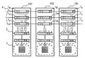
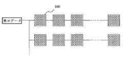
同一データバス上にLEDユニットが接続されている様子を、図1に示す。各LEDユニットは、ケーブルなどにより表示データを共通して転送するようデータバスをなしているが、そのデータバス上で表示データは発光色の種類ごとに割り振られ各LEDユニットのデータ格納手段により、転送し格納される。本発明のLED表示装置では、上述したように、発光色の種類が少ないLEDユニットにおいて、発光色の種類に対応するデータ格納手段に加えて、発光色の種類が多い他のLEDユニットに合わせてデータ格納手段を有し、発光色に割り振られた表示データを同一データバス上の各LEDユニットに転送し、格納することができる。具体的には、各ユニットが有するデータ格納手段であるシフトレジスターは、図に示すように、入力された表示データは、発光色の種類ごとに、それぞれ対応するシフトレジスターに格納され、制御部で階調などが処理され、点灯出力回路により、表示部の各LEDが点灯される。この時、従来のように、同一種類のLEDユニットであれば、上記の通りであるが、本発明のように種類の異なるLEDユニットが接続されている場合には、必ずしも発光色に対応してデータ格納手段が設けられていないため、後述するように制御部若しくは駆動を担うモジュール内部での処理が異なる。
【0021】
従って、本発明のLED表示装置は、同一データバス上に種類の異なるLEDユニットを複数個接続されたものを少なくとも有しており、このデータバス上にある各LEDユニットが備えるデータ格納手段が上記のように同等なものである。すなわち、従来のLED表示装置と同様に、発光色の種類に対して割り振られた表示データをデータバス上の各LEDユニットに転送させ、格納させることができる。
【0022】
ここで、表示データは、図1ではシフトレジスタで示すように、各LEDユニットにあるデータ格納手段を通って、各LEDユニットはケーブルでもって繋がれ、データの流れの終端部に位置するLEDユニットのシフトレジスタから表示データを貯めていき、全てのユニットのシフトレジスタに表示データが格納されたところで、ラッチされ、ロジック回路に入力される。
【0023】
本発明において、LEDユニットにあるデータ格納手段とは、1画素を構成する発光色の種類1つに対し1つ割り当てられるもので、各データ格納手段には発光の種類ごとの表示データが、格納される。
【0024】
本発明において1画素とは、LEDユニットにおけるドットマトリクス状の表示部の1ドットであり、発色の単位である。更に、画素は、1種類以上の発光色により構成され、これらの発光色には、それぞれ1個以上の発光素子(LED)が用いることで、構成されている。例えば、画素が発光色の種類としてRGB三色(種類)からなる場合には、R,G,Bの3つの発光色を1画素とすることであり、これには輝度、演色性などの関係から1つの発光色に対して2個以上のLEDを用いても良い。具体的には、RGBの3色を、LED4個で構成しても良く、他の色と比較して輝度の低いLEDを2個とし1画素としたものでも良い。ここで、発光色の種類としては、同一の発光色若しくは同色系の発光色を有する発光素子RGB三色を例示したが本発明はこれに限定されず、様々なLEDを組み合わせて1画素としたものが利用できる。
【0025】
また、上記発光色の種類が少ないLEDユニットでは、他のLEDユニットのデータ格納手段に対して、その不足分を補うように設けられたデータ格納手段(例えば、前記第3のデータ格納手段)を、本発明では発光色に対して少なくとも一部を用いて、様々な表現をLEDユニットに持たせることができる。すなわち、発光色に対応しないデータ格納手段を、発光色に対応しているデータ格納手段に加えて、つまり1種類の発光色に対して2つ以上のデータ格納手段を割り当てることである。この時、発光色に対応しない前記データ格納手段の全てをLEDの発光に利用しなくても良い。以下、2種類以上の発光色に対応するデータ格納手段を、1種類の発光色に対し用いて、様々な画像を表現する方法について説明する。
【0026】
先ず1つの方法として、1種類の発光色に対して2種類以上の発光色に対応するデータ格納手段を用いて、その発光色を多階調化することである。これは、発光色ごとに、表示データとして多ビットのデジタルデータが供給され、そのデータに応じた階調表現が可能であるが、本発明ではこれに加えて余剰のデータを割り当て多階調化することである。すなわち、画素を構成する発光色の種類が少なく、他のLEDユニットに対応するよう第3のデータ格納手段が設けられ、その発光色の種類より多くのデータ格納手段を有するLEDユニットにおいて、その余剰のデータ格納手段を用いて、それに格納される表示データを加え合わせて、更に多ビット化したデジタルデータとし、それをもとにした階調データでもって発光色のLEDを点灯する。この方法は、制御部において大幅な設計変更を必要とせずに実現が可能であり、設定の変更により様々なLEDユニットを生み出すことができる。
【0027】
もう1つの方法として、1種類の発光色に対して2種類以上の発光色に対応するデータ格納手段を用いて、その表示部におけるドット数を増やすことである。これは、各データ格納手段に格納される表示データにより、画素を構成する発光色の種類ごとに、所定ドット数のLEDアレイの表示部を表示することが可能であるが、この時、このデータ格納手段で表示可能な所定ドット数のLEDアレイの数を増やすことで、表示部全体のドット数を増やすことができる。すなわち、画素を構成する発光色の種類が少なく、他のLEDユニットに対応するよう第3のデータ格納手段が設けられ、その発光色の種類より多くのデータ格納手段を有するLEDユニットにおいて、1種類の発光色に割り当てられるデータ格納手段により表示可能な所定ドット数のLEDアレイを最小単位とし、この最小単位ごとに、それぞれ余剰分を加えたデータ格納手段を発光色の種類に応じて用いることである。従って、画素を構成する発光色の種類が少ないLEDユニットにおいて、余剰分のデータ格納手段を加えたデータ格納手段でもって、前記最小単位に分割された表示部ごとに、発光色の種類に応じた表示データを供給し、表示する。この最小単位とは、例えば画素が1種の発光色で構成され、16×16ドットの表示部を有していた場合に、1種の発光色に対応するデータ格納手段により表示が可能であれば、この16×16ドットが最小単位となる。すなわち、各発光色に対応するデータ格納手段により表示可能なドット数が最小単位となり、前記第3のデータ格納手段を加えた余剰分のデータ格納手段を、分割された最小単位ごとに、さらにその発光色の種類ごとに対応させることで、最小単位の組み合わせによる表示部全体の表示が可能となる。
【0028】
このような方法は、単に、表示部のドット数を増やし、それに対応するようなデータ格納手段を設けてLEDユニットと同様な表現が可能であるが、そのためには、データ格納手段の変更、制御部内での表示データの処理の流れが大きく異なるため、1から設計をやり直す必要がある。本発明においては、余剰分のデータ格納手段を用いて、表示部のドット数を増やしているため、上記最小単位をもとにしたドット数の増加に限定されるが、上記の大幅な設計変更を必要とせずに、従来の制御部を用いて実現でき、容易に表示部のLEDアレイを増やすことができる。
【0029】
これらの2つの方法を組み合わせて、1種類の発光色に対して多階調化、ドット数の増加を同時に行ってもよく、更に2種類以上の発光色に対してそれぞれの方法を若しくはその組み合わせを適用してもよいことはいうまでもない。
【0030】
ここで、発光色の種類が少ないLEDユニットにおけるデータ格納手段を、発光色への対応の有無で表現したが、これは表示部のLEDアレイを表示するのに必要な表示データが発光色に対して割り当てられることを意味するものであり、図1に観るようにデータ格納手段1が明確に発光色ごとに形成されている必要はなく、表示データが各発光色ごとに供給されるような構成であれば足りる。
【0031】
以上のように本発明では、LEDユニットによって、格納される表示データの全てを表示部のLEDの発光に用いない場合もあるが、その方法について本発明は特に限定されない。LEDの発光に用いない表示データの処理として、例えばデータ格納手段に対して格納されたデータを取り込む手段を少なくする、若しくは制御部内に取り込んで対応するデータに対する点灯出力回路が表示部と接続されていない等の方法がある。
【0032】
【実施例】
以下、本発明の実施例を図面に基づいて説明する。なお、以下の実施例は本発明の技術的思想を具体化するものであって、本発明はこれらの実施例に限定されされない。
【0033】
LED表示装置を構成するLEDドットマトリクスユニットの1つが、赤、緑、青の3画素を各々1個のLEDを1ドットとして16行×16列(16×16ドット)に配列したものである場合、このLEDユニットを図1に示す。このLEDユニットは、図1に示すように、データ格納手段として、シフトレジスターを有している。このシフトレジスターで表示データを1ビットずつシフトしていき、コントローラ等から入力された表示データが、データバス上の各LEDユニットのシフトレジスターに転送される。全てのLEDユニットのシフトレジスターに、表示データが転送され、ラッチ回路を有する図のロジック回路にラッチし、表示部の各LEDを発光させる点滅データなどの表示信号を点灯出力回路に送り、点灯出力回路により各LEDが点灯される。
【0034】
ここで、表示部はR,G,B3画素は赤、緑、青色のLED1個ずつを用いており、それぞれの画素に対応するデータ格納手段として図1に示すように、R,G,Bの表示データを格納するシフトレジスターを具備している。
【0035】
図の例では、16×16ドットのLEDユニットであるため、RGBの各シフトレジスターに格納された、表示部のLEDアレイの1列目から16列目までの表示データが、制御・駆動部内にラッチされ、表示部の1行目のLEDが点灯する。この動作を、16行目まで高速で繰り返し、表示部の1フレームの点灯が行われる。この時、表示データが8ビットのデジタル信号であると、RGBのLEDが256階調で点灯され、LEDユニットは、16万色の表現が可能となる。
【0036】
以下、このLEDユニットを有する表示装置の実施例を示すが、本発明は特にこのLEDユニットを有する必要はなく、その他のLEDユニットとの任意の組み合わせが可能であることは、いうまでもない。
【0037】
[実施例1]
表示装置を構成するLEDユニットの内、図1に示すように、マルチカラー、モノクロ、マルチカラーユニットの並びで接続された場合について、以下説明する。
【0038】
図の2つのマルチカラーユニット101は、上述したものと同等で、発光色としてR,G,Bの3種に対して各1個ずつ発光素子を用いた画素であり、これを1ドットとして表示部3は16×16ドットのマトリクスディスプレイである。モノクロユニット102は発光色が1種で白色発光のLED1個を1画素とし、16×16ドット配列されたものである。従来、この様なモノクロユニットは、1画素を1種類の発光色、1個のLEDで構成しているため、これに対応する表示データを転送するデータ格納手段も1つしか必要でなく、例えば1個のシフトレジスターを有していた。
【0039】
ここで、本実施例に用いた白色発光のLED(1チップ)としては、蛍光体を用いたLED、発光層が多重量子井戸構造(MQW)のLEDがある。詳しくは、蛍光体を用いたLEDは、発光素子からの発光を色変換する物質をチップ上に塗布したものや、封止剤に混入させたものなどがある。また、MQWの白色LEDは、発光層が多重量子井戸構造であり、その発光層に発光ピーク波長が短いものと、長いものがあり、その混色光で白色発光を実現している。具体的には、多重量子井戸構造の井戸層がInGaNであり、この井戸層にIn含有量の多い、すなわち発光ピーク波長が長い第1の発光層と、In含有量の少ない(発光ピーク波長が短い)第2の発光層とを有することで、混色光として白色発光のLEDとなる。この時、第1,2の層は、第1をp型電導層側に設けることが好ましく、各層は複数の層からなっていてもよい。また、各発光色の強度比は、各波長に係る層の積層比乃至はその数、及び/又は井戸層を挟む障壁層の厚さで制御できる。本実施例では、モノクロ(白色)のLEDユニットとしてMQWの白色LEDを使用した。
【0040】
本実施例の表示装置では、モノクロユニットには、データ格納手段として、3つのシフトレジスター(1R,1G,1B)を有しており、この内1つのシフトレジスターが利用され、すなわち図ではマルチカラーユニットにおける緑の表示データが供給されるバスライン上のシフトレジスター1Wを利用し、これに格納された表示データが矢印に示すように制御部に送られ、白色のLEDを点灯する。モノクロユニットに残された、2つ(R,B)のシフトレジスター1p1,1p2、若しくはそこに格納された表示データは、表示部の各LEDの点灯に利用されることなく無視され、データラインの下流にあるマルチカラーユニット101に表示データ(R,B)を受け渡す、経路としての役割を果たしている。
【0041】
白色ユニットにおいて、制御部は、上述したように従来の白色1種を扱う従来の白色LEDユニット用のものを用いてもよく、またマルチカラー用の制御部を用いて、元来緑色に用いていた点灯出力回路を白色LEDの表示部に繋げて接続して、他の出力回路の出力側には何も接続しないものであってもよい。その他の方法として、制御部内で不要の表示データを破棄するような機構を持たせたものを使用しても良い。
【0042】
このようにして、得られるLED表示装置は、モノクロ、マルチカラーのパネルを任意に配置することができ、様々な画像の表示に対応することができる。また、各LEDユニットを組み上げる際にも、従来通り各ユニットを並べて隣接するユニット同士をケーブルで接続するだけの作業で足りる。
【0043】
[実施例2]
次に、実施例1のモノクロユニット102に代わり、図2に示す2色ユニット103がマルチカラーユニットに挟まれて、構成されているLED表示装置について説明する。この2色ユニット103は、画素として赤色LEDチップと青緑色LEDチップからなる2色LED1個(2種の発光色)で構成され1ドットとし、16×16でドットマトリクス状に配列されている。この時、2色LEDとしては、2つのLEDチップが、同一のリード(メインリード)に設けられたカップ上にダイボンドされ、各LEDチップの一方の電極を接続し、他方の電極を2つのサブリードに接続し封止されたもの、2つのLEDチップがそれぞれ別々のリードのカップにダイボンドされて、各LEDの他方の電極はもう1つのリードに接続され、各チップに個別にレンズ効果が付与されるように樹脂モールドで封止されたもの等のLEDランプ、若しくはプリント基板に2つのLEDチップが実装され、樹脂モールドで一体に封止されたものなどが用いられる。また、2つのLEDチップの発光色としては、本実施例では、各LEDチップの色を、色度図(例えば、CIEのXY表色色度図)上の2点で表したとき、その2点を結ぶ直線が白色領域を通るように選択されたものを使用している。今日、多く観られる赤、緑色の2色LEDでは、その表示が人間の目には全体的に単調な橙近似の色にみえる。しかし、本実施例の様に、白色表現が可能な2色LEDであるため、発光色は白色を含む中間色が多彩に表現され、またRGBのマルチカラーユニットとの組み合わせでは、LED表示装置全体が単調な色調にならず、疑似カラーとして相性も良い。他には黄色と青色の組み合わせなどがある。
【0044】
この様な並びの各ユニットを有するLED表示装置では、実施例1と異なり、3つあるシフトレジスターの内、2つ(1R,1BG)に格納された表示データにより画素を構成する2種の発光色に用いられ、表示部のLEDが発光される。図では、マルチカラーユニットの発光色緑色と青色に対応するシフトレジスター(1R,1BG)に格納された表示データを、画素を構成する赤色、青緑色の発光に用いる。この時、どのデータ格納手段を、画素を構成する各発光色に割り当てるかは、任意に設定できる。利用されないシフトレジスター1Pは、実施例1と同様に表示データの経路として利用されている。実施例1と同様に、不要となる表示データは、LEDの発光に用いない。また、制御部に関しても実施例1と同様に、従来2色LEDユニットに用いられていたものを利用しても良く、マルチカラー用のそれを利用しても良い。
【0045】
従って、実施例1,2において、発光色の種類が少ないLEDユニットでは、その差分を補う形で、データ格納手段(第3のデータ格納手段)を新たに加える、若しくは、発光色の種類が多いLEDユニットにおける表示部のLEDアレイを変更するだけで、ほぼ実現可能である。すなわち、大幅な設計変更などの必要が無く、そのほとんどが従来品を流用することで実現可能であり、様々なLED表示装置に対して柔軟に対応・設計できる。
【0046】
[実施例3]
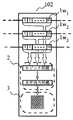
更に、本発明における別の実施の形態として、実施例1(図1)と同様なLEDユニットの並びを有するLED表示装置について、白色ユニットにおける表示データの取り込みが図3に示す通りであるLED表示装置について説明する。マルチカラーユニットに送られる表示データは、画素を構成するRGB(3種の発光色)に対応するシフトレジスター(1R,1G,1B)に、それぞれ3ビット(8階調)のデジタルデータが入力され、ユニットとしては3色で、512階調の表示が可能である。表示部2は、RGBそれぞれに対して1個の発光素子を用いて、それを1ドットとし16×16ドットのマトリクスディスプレイである。図4のモノクロユニット(1ドットが1個の白色LED,画素を1種の発光色で構成)では、マルチカラーユニットのRGBに対応する3つのシフトレジスター(1W1,1W2,1W3)に格納された表示データを全て制御部2に取り込み、制御部内のロジック回路で、白色に対する9ビットのデジタルデータとして処理され、点灯出力回路に白色の信号として入力され、表示部3において16×16ドットで512階調のグレースケール表示が可能となる。
【0047】
詳しくは、入力された表示データは、階調制御回路等により階調データ部分をそれに対応する時間幅で発光するよう点灯出力回路に信号を供給し、各発光色の明るさが調整される等して、階調表現される。上記白色LEDユニットでは、取り込まれた3種の発光色に相当する表示データを、前記階調制御回路などにより1種の発光色(白色)に対して用い、多階調化した階調データとして点灯出力回路に供給され、表示部のマトリクスディスプレイが3つの表示データに相当する多階調表現が可能となる。実施例では、3種の発光色に対応する表示データを全て用いているが、必ずしも全ての表示データを用いる必要はなく、2種であっても良い。すなわち、実施例1との組み合わせた表示形態も可能であり、具体的には、余剰分のデータ格納手段の内、一部を多階調化に用い、残りは表示に利用しないとしたものであっても良い。
【0048】
[実施例4]
本発明における別の実施の形態として、実施例2と同様なLEDユニットの並びを有するLED表示装置であって、2色ユニットにおける表示データの表示データの取り込みが図4に示すような形態の実施例について、以下説明する。実施例2と異なり、図4に示すように、2色ユニットの3つのシフトレジスター(1R,1BG1,1BG2)を全て2種の発光色に割り当て(1つを赤色に、2つを青緑色)、各シフトレジスターに格納された表示データを制御部2に取り込み、実施例3と同様な処理によりその内部にあるロジック回路の出力側で、赤色は3ビット8階調、青緑色は6ビット64階調のデジタルデータとなる。すなわち、表示部では、赤8階調と青緑64階調で512階調の16×16ドットマトリクスユニットとなっている。
【0049】
このような、2色ユニットは、上述したように色度図上における2点を結ぶ直線において、青緑から白色領域の間にある、中間色が多階調化され、その表現力が増し、様々な用途への応用が可能である。
【0050】
このように、発光色の種類が少ないLEDユニットで、各発光色に対応するデータ格納手段に、更に他のLEDユニットとの差分を補うよう設けられたデータ格納手段(第3のデータ格納手段)を加えて、それらの表示データを用いることで、複数種ある内の少なくとも1種の発光色に対して多階調化することが、容易に可能である。このことにより、得られるLED表示装置は、階調表現に優れたものとなり、用途の幅が広がる。
【0051】
[実施例5]
本発明における他の実施の形態として、実施例1における白色LEDユニットに代わり、図5に示すLEDユニットを有するLED表示装置について説明する。図5は、実施例1と同様にLEDユニットが並んでいるが、モノクロユニットは、図に示すように表示部が16×48ドットのアレイである。実施例3と同様に3つあるシフトレジスター(1W1,1W2,1W3)に格納された表示データは、制御部2に取り込まれ、マルチカラーユニットのRGB3種の発光色に対応するデータは、表示部のW1〜W16,W17〜W32,W33〜W48として配分され、各白色LEDが点灯される。
【0052】
このとき、モノクロユニットは、3つのシフトレジスターからデータを取り込んでいるが、3つの内2つのシフトレジスターから、表示データを取り込んで16×32の表示部の各LEDを点灯しても良い。また、図5では、表示部は理解しやすいように、各LEDアレイ(16×16ドット)を離間して横に並べているが、特にこの図にとらわれる必要はなく、はじめから16×48(48×16)ドットのディスプレイとしても良いし、縦に並べて配置しても良い。
【0053】
すなわち、表示部を、上述した最小単位のドット数を組み合わせたものを使用するだけで、容易に表示ドット数の大きなLEDユニットが形成できる。具体的には、本実施例に用いる白色LEDユニットは、表示部以外の部分をマルチカラーのものを流用し、各発光色ごとに割り振られる表示データに代わり、前記最小単位に分割された表示部(所定ドット数のディスプレイ部)に供給されて表示部全体が表示される。このようなLEDユニットを有するLED表示装置は、ある特定の発光色種のLEDユニットにだけ、ドット数を多くできるため、面積の大きな、自由な表示部のLEDパネルの配置が可能で、表現力豊かなLED表示装置が従来のLEDユニットの資産で、容易に実現可能となる。
【0054】
[比較例1]
図6に示すように、マルチカラーと白色ユニットを混在させる場合、表示データの流れに対して、終端部に位置するように白色ユニットを配置して、1つ手前のマルチカラーユニットから、Bに対応する表示データだけを入力するように、接続する。表示データは、それに対応するように送られ、表示が可能となる。
【0055】
しかし、このような方法では、画素数の少ないユニット(本実施例では白色ユニット)の位置が限定され、なおかつ1つしか配置することができない。
【0056】
[比較例2]
図7に示すように、各種類のLEDユニットごとに異なるデータ転送経路を用意し、見掛け上混在しているLED表示装置を作製した。
【0057】
しかし、このようなLED表示装置では、2系統若しくはそれ以上の経路が必要であり、表示データを出力するコントロール部での処理が多くなる。さらに、LEDアレイを見掛け上混在しているように見せるため、各LEDユニットを繋ぐケーブルは必然的に長くなり、データの信頼性を確保するため高周波での動作が困難となり、また長いケーブルをパッケージングするためのスペースも必要となり、LED表示装置の容積が大きくなる。また、LED表示装置の組立作業も煩雑なものとなり、表示装置が大きくなると設置コストが高くなる。
【0058】
【発明の効果】
本発明のLED表示装置は、異なるドットマトリクスユニットを混在させる場合に、従来のように2系統の入力ラインを必要としないため、どのようなユニットの組み合わせで構成されるLED表示装置であっても、そのための特別な入力回路側の設計を必要とせずに、マルチカラーのユニットに用いた入力回路をそのまま利用して、LED表示装置製造することができる。また、従来のものでは同種類のユニット同士を接続するケーブルの長さが、LED表示装置における各ユニットの配置に大きく左右され、同一のユニットで構成されるLED表示装置のそれに比べて、長くなるため、信頼性低下、高周波での動作不可能になるが、本発明のLED表示装置は、構成するユニットの数が同じであれば、それらを接続するケーブルの長さも同じであるため、従来の単一のユニットで構成されるLED表示装置と同様の条件での動作が可能となった。
【0059】
さらに、本発明のLED表示装置では、従来の異なるユニットからなるLED表示装置に比べて、各LEDユニットの組立作業が容易であり、従来のLEDユニットの部品、蓄積された技術を流用するだけで容易に多彩な表現の可能なLED表示装置が得られる。
【図面の簡単な説明】
【図1】本発明の1実施例に係るLEDユニットが並んだ状態を示すブロック線図。
【図2】本発明の1実施例に係るLEDユニットのブロック線図。
【図3】本発明の1実施例に係るLEDユニットのブロック線図。
【図4】本発明の1実施例に係るLEDユニットのブロック線図。
【図5】本発明の1実施例に係るLEDユニットのブロック線図。
【図6】従来例に係るLEDユニットの並びを示すブロック線図。
【図7】従来例に係るLEDユニットの構成を示すブロック線図。
【図8】LED表示装置を示すブロック線図。
【符号の説明】
1・・・・シフトレジスタ(データ格納手段)
2・・・・制御部
3・・・・表示部
4・・・・データバス
100・・・・LEDユニット
101・・・・マルチカラーLEDユニット
102・・・・白色(モノクロ)LEDユニット
103・・・・2色LEDユニット[0001]
[Industrial application fields]
The present invention relates to an LED display device having a plurality of LED units in which a plurality of LEDs are arranged in a matrix, and to an LED display device having a high degree of freedom in the type, arrangement, or expression of each LED unit.
[0002]
[Prior art]
2. Description of the Related Art An LED display device that displays an image by arranging a plurality of LEDs vertically and horizontally and further arranging a plurality of LED units is used for various applications. Some LED display units, for example, red, green, blue, that is, three RGB LEDs are brought close to each other to form one pixel and arranged in a matrix to realize a multi-color LED display unit. There are LED units, etc., in which red, green and two-color LEDs are used as one pixel.
[0003]
For example, in the case of a multi-color LED display unit having a structure in which one pixel is formed with LEDs of different emission colors, the emission luminance of each color (RGB) LED is controlled by gradation data, The brightness is adjusted.
[0004]
Due to the advancement of LEDs, two-color LED units with relatively old pixels of red, green or the same color as one pixel, and LED units consisting of one single-color LED for various light emission Display and representation of images by color is now possible. However, these LED units are usually arranged in an LED display device by arranging a plurality of the same types, but LED display devices in which different LED units are mixed are not often used.
[0005]
However, as described above, various types of LED units have been developed due to the recent increase in color and brightness of LEDs, so that these LED units can be combined in a complex manner depending on the application, and a wide variety of displays can be achieved. There is a need for possible display devices.
[0006]
[Problems to be solved by the invention]
Such LED display devices that combine different types of LED units such as multicolor and single color, for example, for each type of LED unit, as shown in FIG. It is most common to provide one data bus line. However, as shown in FIG. 7, in such a method, a certain limitation is added to the expression form of the LED display device, the length of the cable connecting the LED units is increased, and the driving frequency is limited. Or
[0007]
It is also possible to connect different LED units in the form of one data bus line. For example, as shown in FIG. 6, a single color LED unit can be connected only to the terminal end in the data transfer direction. Limits on the arrangement of units.
[0008]
Furthermore, connecting the LED units with complicated wiring in this way makes the work of assembling the LED display device complicated, and also requires an extra space for connecting the LED units. The size of the entire LED display device is increased.
[0009]
[Means for Solving the Problems]
The present invention has been made to solve the above-described problems, and can be handled in the same manner as a conventional LED display device in which a plurality of LED units having the same emission color type are arranged, and further, a module for lighting and driving LEDs. The LED display device which can be used also as a part and can be easily assembled to provide various expressions can be provided. It is possible to arbitrarily arrange LED units of different types by making the number of data storage means that each LED unit has the same regardless of the type of luminescent color, and in LED units with few types of luminescent color. It is possible to ignore the excess display data or to increase the number of dots in the display portion and the multi-gradation expression with the display data.
[0010]
That is, the LED display device of the present invention has the following configurations (1) to (3).
[0011]
(1) A first display unit having a plurality of light emitting elements and pixels that emit one or more kinds of emission colors arranged in a matrix, and a first display unit that sequentially transfers and stores display data corresponding to each of the emission colors. A first LED unit having at least a first data storage unit, and a first control unit that controls lighting of each light emitting element by display data stored in the first data storage unit, and the first LED unit There are fewer types of emission colors than the second display unit in which pixels using each emission color are arranged in a matrix, and second data storage for sequentially transferring and storing display data corresponding to each of the emission colors And a second LED unit having a second control unit for controlling the lighting of each light emitting element by the display data stored in the second data storage unit, the first LED unit and the second LED unit An LED display device in which a data bus for commonly transferring display data to each data storage means of the LED unit is electrically connected, wherein the second LED unit is in addition to the second data storage means. And third data storage means provided corresponding to the first data storage means. As a result, the light emission color is different and the data storage means is different as in the prior art, so that the connection using the same data bus is impossible or it is necessary to connect via some data conversion means. The one LED unit and the second LED unit can be connected on the same bus with any arrangement, and various display devices can be obtained.
[0012]
(2) The second unit is characterized in that at least one kind of light emission color is subjected to multi-gradation by the stored display data using the third data storage means. The third data storage means for compensating for the difference between the different LED units is to be used effectively, and the display data stored here is added to the display data of the second data storage means, so that the second data Compared to the case where only the storage means is used for display, the second LED unit can have multiple gradations. That is, a display device composed of LED units having different gradations can be easily realized without requiring complicated design changes.
[0013]
(3) In the second unit, the second display unit is divided into at least two or more groups, and the third data storage means is allocated to the divided groups, and the storage is performed. According to the display data, the LED of each set of the display unit is lit. Accordingly, the number of pixels of the second LED unit can be easily increased only by changing the design of the second display unit, and a display device including LED units having different numbers of pixels can be easily realized. Is.
[0014]
DETAILED DESCRIPTION OF THE INVENTION
FIG. 8 shows an overall block diagram of the display device of the present invention. The display device of this block diagram is configured such that a plurality of LED dot matrix units are connected via a distribution board or the like, and display data is input to the data storage means. Each LED unit takes in a display unit in which pixels made of LEDs are arranged in a matrix, data storage means for transferring and storing display data, and display data stored in the data storage means to control lighting of each LED And a control unit.
[0015]
Each LED unit includes a dynamic lighting method in which the LEDs are divided into a plurality of groups and the divided LEDs are lighted in a time division manner, and a static lighting method in which the LEDs are not divided. In this way, one cycle for turning on the LED of the display unit is called one frame. For example, in the case of dynamic lighting and the display unit is 16 × 16 dots, one image is 16 msec (frequency is 60 Hz). ), The display time for one column is 1 msec. At this time, the LEDs in one row may perform gradation expression by controlling the lighting time for 1 msec to gradation data and adjusting the light emission luminance.
[0016]
In the conventional LED display device, as shown in FIG. 8, each LED unit connected by a cable or the like and connected on one data bus has the same kind of light emission color constituting the pixel. For example, a plurality of multi-color LED units each having three colors of RGB, one pixel for each light emitting element, are connected to the data bus.
[0017]
However, in the LED display device of the present invention, LED units having various types of light emission colors as pixels are arbitrarily arranged on the data bus. More specifically, the LED units on the same data bus have at least two LED units having different emission colors.
[0018]
For example, if there are two types, the first LED unit having a large number of emission colors and the second LED unit having a small number of emission colors, each LED unit has a first and second data storage means and a control unit. The second LED unit further includes second data storage means corresponding to the emission color, and in addition, third data storage means not corresponding to the emission color. Yes. Specifically, since the second LED unit has few types of light emission colors constituting the pixel, the data storage means (second data storage means) necessary for the display is the data storage of the first LED unit. It is different from the means (first data storage means), and each LED unit cannot be arranged at an arbitrary position on the same data bus as it is. For this purpose, by adding a third data storage means corresponding to the difference between the first and second data storage means to the second LED unit, some data changing means is interposed on the same data bus. Each LED unit can be easily connected with a cable or the like, and can be arbitrarily arranged.
[0019]
Here, the present invention is not limited to the two types of LED units, and may be three or more types. For example, even when three or more types of LED units are on the same data bus, the first and second LED units whose emission color types have the above relationship are selected, and the data storage means is set in the same manner. You should consider it. At this time, in each LED unit, the light emission color to which the data storage means is associated, that is, the one having the largest number of types of light emission colors, and the LED unit having a smaller number are provided with data storage means corresponding to the difference. You can do it.
[0020]
FIG. 1 shows a state in which LED units are connected on the same data bus. Each LED unit has a data bus so that display data is commonly transferred by a cable or the like, but the display data is allocated to each type of emission color on the data bus, and the data storage means of each LED unit Transfer and store. In the LED display device of the present invention, as described above, in the LED unit having a small number of types of light emission color, in addition to the data storage means corresponding to the type of light emission color, in accordance with another LED unit having a large number of types of light emission color. Data storage means is provided, and display data assigned to the emission color can be transferred to and stored in each LED unit on the same data bus. Specifically, as shown in the figure, the shift register, which is a data storage means included in each unit, stores the input display data in the corresponding shift register for each type of luminescent color. The gradation is processed, and each LED of the display unit is lit by the lighting output circuit. At this time, if it is the same type of LED unit as in the conventional case, it is as described above. However, when different types of LED units are connected as in the present invention, it always corresponds to the emission color. Since no data storage means is provided, the processing in the control unit or the module responsible for driving is different as will be described later.
[0021]
Therefore, the LED display device of the present invention has at least a plurality of different types of LED units connected on the same data bus, and the data storage means included in each LED unit on the data bus includes the above-described data storage means. Are equivalent. That is, as with the conventional LED display device, display data allocated to the type of light emission color can be transferred to and stored in each LED unit on the data bus.
[0022]
Here, as shown by the shift register in FIG. 1, the display data passes through the data storage means in each LED unit, and each LED unit is connected by a cable, and the LED unit is located at the end of the data flow. The display data is stored in the shift registers of the units, and when the display data is stored in the shift registers of all units, it is latched and input to the logic circuit.
[0023]
In the present invention, the data storage means in the LED unit is assigned to one type of light emission color constituting one pixel, and display data for each light emission type is stored in each data storage means. Is done.
[0024]
In the present invention, one pixel is one dot of the dot matrix display portion in the LED unit, and is a color developing unit. Furthermore, the pixel is composed of one or more kinds of emission colors, and each of these emission colors is constituted by using one or more light emitting elements (LEDs). For example, when a pixel is composed of three colors (types) of RGB as the types of light emission colors, the three light emission colors of R, G, and B are set as one pixel, which is related to luminance, color rendering, and the like. Thus, two or more LEDs may be used for one emission color. Specifically, the three colors of RGB may be configured by four LEDs, or two LEDs having lower luminance than the other colors may be used as one pixel. Here, as the types of luminescent colors, three light emitting elements RGB having the same luminescent color or the same luminescent color are exemplified, but the present invention is not limited to this, and various pixels are combined into one pixel. Things are available.
[0025]
In addition, in the LED unit with a small number of types of emission colors, a data storage unit (for example, the third data storage unit) provided to compensate for the shortage of the data storage unit of other LED units is provided. In the present invention, the LED unit can have various expressions by using at least a part of the emission color. That is, in addition to the data storage means corresponding to the emission color, the data storage means not corresponding to the emission color is to assign two or more data storage means to one kind of emission color. At this time, it is not necessary to use all of the data storage means not corresponding to the emission color for the light emission of the LED. Hereinafter, a method for expressing various images by using data storage means corresponding to two or more types of emission colors for one type of emission color will be described.
[0026]
One method is to use a data storage unit corresponding to two or more types of emission colors for one type of emission color to make the emission colors multi-gradation. This is because multi-bit digital data is supplied as display data for each luminescent color, and gradation representation according to the data is possible. It is to be. That is, there are few types of light emission colors constituting the pixel, and the third data storage means is provided so as to correspond to other LED units, and the LED unit having more data storage means than the types of light emission colors has its surplus. By using the data storage means, the display data stored in the data storage means is added to obtain digital data having a larger number of bits, and the light emitting color LED is turned on with gradation data based on the digital data. This method can be realized without requiring a significant design change in the control unit, and various LED units can be generated by changing the setting.
[0027]
Another method is to increase the number of dots in the display unit using data storage means corresponding to two or more types of emission colors for one type of emission color. The display data stored in each data storage means can display the display section of the LED array having a predetermined number of dots for each type of luminescent color constituting the pixel. By increasing the number of LED arrays having a predetermined number of dots that can be displayed by the storage means, the number of dots in the entire display unit can be increased. That is, in the LED unit having a small number of emission colors constituting the pixel and having third data storage means corresponding to other LED units and having more data storage means than the emission color types, one type LED storage of a predetermined number of dots that can be displayed by the data storage means assigned to the light emission color is set as the minimum unit, and data storage means obtained by adding a surplus for each minimum unit is used according to the type of light emission color. is there. Therefore, in an LED unit with a small number of types of light emission colors constituting a pixel, the data storage means to which the data storage means for surplus is added, and the display units divided into the minimum units correspond to the types of light emission colors. Supply and display display data. The minimum unit is, for example, when a pixel is composed of one kind of light emission color and has a display portion of 16 × 16 dots, and can be displayed by the data storage means corresponding to one kind of light emission color. For example, this 16 × 16 dot is the minimum unit. That is, the number of dots that can be displayed by the data storage means corresponding to each emission color is the minimum unit, and the data storage means for the surplus including the third data storage means is further divided for each divided minimum unit. By making it correspond to each kind of luminescent color, it becomes possible to display the entire display unit by a combination of minimum units.
[0028]
Such a method can be simply expressed by increasing the number of dots in the display unit and providing data storage means corresponding to the number of dots, but for this purpose, the data storage means can be changed and controlled. Since the processing flow of display data in the department is greatly different, it is necessary to start the design from scratch. In the present invention, since the number of dots in the display unit is increased by using the surplus data storage means, it is limited to the increase in the number of dots based on the minimum unit. Can be realized using a conventional control unit, and the LED array of the display unit can be easily increased.
[0029]
By combining these two methods, it is possible to increase the number of gradations and increase the number of dots simultaneously for one type of luminescent color. Furthermore, each method for two or more types of luminescent colors or a combination thereof. It goes without saying that may be applied.
[0030]
Here, the data storage means in the LED unit with a small number of emission colors is expressed by the presence or absence of the correspondence to the emission color. This is because the display data necessary to display the LED array of the display unit corresponds to the emission color As shown in FIG. 1, the data storage means 1 does not have to be clearly formed for each emission color, and the display data is supplied for each emission color. If it is enough.
[0031]
As described above, in the present invention, there are cases where not all of the display data stored by the LED unit is used for light emission of the LED of the display unit, but the present invention is not particularly limited with respect to the method. As processing of display data that is not used for LED light emission, for example, the number of means for fetching data stored in the data storage means is reduced, or a lighting output circuit for the corresponding data fetched in the control section is connected to the display section. There is no way.
[0032]
【Example】
Embodiments of the present invention will be described below with reference to the drawings. The following examples embody the technical idea of the present invention, and the present invention is not limited to these examples.
[0033]
When one of the LED dot matrix units that make up the LED display device is an array of 16 rows x 16 columns (16 x 16 dots), each consisting of three pixels of red, green, and blue, each with one LED as one dot This LED unit is shown in FIG. As shown in FIG. 1, this LED unit has a shift register as data storage means. The display data is shifted bit by bit by this shift register, and the display data input from the controller or the like is transferred to the shift register of each LED unit on the data bus. Display data is transferred to the shift registers of all LED units, latched in the logic circuit shown in the figure having a latch circuit, and a display signal such as blinking data for causing each LED of the display unit to emit light is sent to the lighting output circuit, and the lighting output Each LED is turned on by the circuit.
[0034]
Here, the display unit uses one red, green, and blue LED for each of the R, G, and B pixels. As shown in FIG. 1, data storage means corresponding to each pixel includes R, G, and B. A shift register for storing display data is provided.
[0035]
In the example in the figure, since the LED unit is 16 × 16 dots, the display data from the first column to the 16th column of the LED array of the display unit stored in each RGB shift register is stored in the control / drive unit. Latched, and the LED in the first row of the display section lights up. This operation is repeated at high speed up to the 16th line, and one frame of the display is turned on. At this time, if the display data is an 8-bit digital signal, the RGB LEDs are turned on with 256 gradations, and the LED unit can express 160,000 colors.
[0036]
Hereinafter, although the Example of the display apparatus which has this LED unit is shown, it cannot be overemphasized that this invention does not need to have this LED unit in particular, and arbitrary combinations with another LED unit are possible.
[0037]
[Example 1]
A case where the LED units constituting the display device are connected in an array of multi-color, monochrome, and multi-color units as shown in FIG. 1 will be described below.
[0038]
The two
[0039]
Here, as the white light emitting LED (one chip) used in this embodiment, there are an LED using a phosphor and an LED having a multiple quantum well structure (MQW) as a light emitting layer. Specifically, the LED using a phosphor includes one in which a substance that changes the color of light emitted from a light emitting element is applied on a chip, and one that is mixed in a sealant. In addition, MQW white LEDs have a light emitting layer with a multiple quantum well structure, and the light emitting layer has a short emission peak wavelength and a long emission wavelength, and realizes white light emission with the mixed color light. Specifically, the well layer having a multiple quantum well structure is InGaN, and the well layer has a high In content, that is, a first light emitting layer having a long emission peak wavelength, and a low In content (the emission peak wavelength is small). By having the second light-emitting layer that is short, it becomes an LED that emits white light as mixed color light. At this time, the first and second layers are preferably provided on the p-type conductive layer side, and each layer may be composed of a plurality of layers. Further, the intensity ratio of each emission color can be controlled by the stacking ratio or the number of layers related to each wavelength and / or the thickness of the barrier layer sandwiching the well layer. In this example, a white LED of MQW was used as a monochrome (white) LED unit.
[0040]
In the display device of this embodiment, the monochrome unit has three shift registers (1R, 1G, 1B) as data storage means, and one of these shift registers is used. Using the shift register 1W on the bus line to which the green display data in the unit is supplied, the display data stored therein is sent to the control unit as indicated by the arrow, and the white LED is turned on. The two (R, B) shift registers 1p1 and 1p2 left in the monochrome unit, or the display data stored there, are ignored without being used to light each LED of the display unit, and the data line It plays the role of a path for transferring display data (R, B) to the
[0041]
In the white unit, as described above, the control unit may be one for a conventional white LED unit that handles one type of conventional white, and is originally used for green color by using a multi-color control unit. The lighting output circuit connected to the white LED display unit may be connected and nothing may be connected to the output side of the other output circuit. As another method, a method having a mechanism for discarding unnecessary display data in the control unit may be used.
[0042]
In this way, the obtained LED display device can arbitrarily arrange monochrome and multi-color panels, and can cope with display of various images. Also, when assembling each LED unit, it is sufficient to simply arrange the units and connect adjacent units with a cable as in the past.
[0043]
[Example 2]
Next, instead of the
[0044]
In the LED display device having the units arranged in this way, unlike the first embodiment, two types of light emission that constitute a pixel by display data stored in two (1R, 1BG) of three shift registers. Used for color, LED of the display unit emits light. In the figure, the display data stored in the shift registers (1R, 1BG) corresponding to the light emission colors green and blue of the multi-color unit are used for light emission of red and blue green constituting the pixel. At this time, it is possible to arbitrarily set which data storage means is assigned to each emission color constituting the pixel. The shift register 1P that is not used is used as a display data path in the same manner as in the first embodiment. As in the first embodiment, unnecessary display data is not used for LED emission. As for the control unit, as in the first embodiment, the conventional one used for the two-color LED unit may be used, or one for multi-color may be used.
[0045]
Therefore, in the first and second embodiments, in the LED unit with a small number of emission colors, a data storage unit (third data storage unit) is newly added or the number of types of emission colors is large to compensate for the difference. This can be almost realized only by changing the LED array of the display unit in the LED unit. In other words, there is no need for drastic design changes, most of which can be realized by diverting conventional products, and can flexibly respond to and design various LED display devices.
[0046]
[Example 3]
Furthermore, as another embodiment of the present invention, for an LED display device having an LED unit arrangement similar to that in Example 1 (FIG. 1), the display of the display data in the white unit is as shown in FIG. The apparatus will be described. Display data sent to the multi-color unit is input as 3-bit (8 gradations) digital data to shift registers (1R, 1G, 1B) corresponding to RGB (three kinds of light emission colors) constituting the pixels. The unit has three colors and can display 512 gradations. The
[0047]
Specifically, the input display data is supplied with a signal to the lighting output circuit so that the gradation data portion emits light with a time width corresponding to the gradation data by the gradation control circuit or the like, and the brightness of each emission color is adjusted. Thus, gradation is expressed. In the white LED unit, display data corresponding to the three kinds of captured emission colors is used for one kind of emission color (white) by the gradation control circuit or the like, and is used as gradation data with multiple gradations. Supplying to the lighting output circuit, the matrix display of the display unit can express multi-tone corresponding to three display data. In the embodiment, all the display data corresponding to the three types of emission colors are used, but it is not always necessary to use all the display data, and two types may be used. That is, a display form combined with the first embodiment is also possible. Specifically, a part of the surplus data storage means is used for multi-gradation, and the rest is not used for display. There may be.
[0048]
[Example 4]
Another embodiment of the present invention is an LED display device having an LED unit arrangement similar to that of the second embodiment, in which the display data of the two-color unit is captured as shown in FIG. An example will be described below. Unlike Example 2, as shown in FIG. 4, the three shift registers (1R, 1BG1, 1BG2) of the two-color unit are all assigned to two types of emission colors (one for red and two for blue-green). The display data stored in each shift register is fetched into the
[0049]
In such a two-color unit, as described above, in the straight line connecting the two points on the chromaticity diagram, the intermediate color between the blue-green and white regions is multi-graded, and its expressive power increases, and various Application to various uses is possible.
[0050]
As described above, the data storage means (third data storage means) is provided in the data storage means corresponding to each light emission color so as to compensate for the difference from the other LED units with the LED units having few kinds of emission colors. In addition, by using these display data, it is possible to easily increase the number of gradations for at least one of the plurality of types of emission colors. As a result, the obtained LED display device is excellent in gradation expression, and the range of applications is widened.
[0051]
[Example 5]
As another embodiment of the present invention, an LED display device having the LED unit shown in FIG. 5 instead of the white LED unit in Example 1 will be described. In FIG. 5, the LED units are arranged in the same manner as in the first embodiment, but the monochrome unit is an array of 16 × 48 dots as shown in the figure. Similar to the third embodiment, display data stored in three shift registers (1W1, 1W2, 1W3) is taken into the
[0052]
At this time, the monochrome unit takes in data from three shift registers, but it may take in display data from two of the three shift registers and light each LED of the 16 × 32 display unit. In FIG. 5, the LED array (16 × 16 dots) is arranged horizontally and spaced apart so that the display unit can be easily understood. However, it is not necessary to be particularly caught in this figure, and 16 × 48 (48 × 16) It may be a dot display or may be arranged vertically.
[0053]
That is, an LED unit having a large number of display dots can be easily formed by using only a combination of the minimum number of dots as described above. Specifically, the white LED unit used in this embodiment uses a multi-color part other than the display unit, and instead of the display data allocated for each emission color, the display unit divided into the minimum units. The whole display unit is displayed by being supplied to the (display unit having a predetermined number of dots). Since the LED display device having such an LED unit can increase the number of dots only in an LED unit of a specific light emission color type, it is possible to arrange an LED panel having a large area and a free display portion, and expressive power. A rich LED display device can be easily realized with the assets of a conventional LED unit.
[0054]
[Comparative Example 1]
As shown in FIG. 6, when multi-color and white units are mixed, the white unit is arranged so as to be positioned at the end portion with respect to the flow of display data, and the multi-color unit from the previous one is changed to B. Connect so that only the corresponding display data is input. The display data is sent correspondingly and can be displayed.
[0055]
However, in such a method, the position of a unit having a small number of pixels (a white unit in this embodiment) is limited, and only one can be arranged.
[0056]
[Comparative Example 2]
As shown in FIG. 7, different data transfer paths were prepared for each type of LED unit, and an LED display device that was apparently mixed was manufactured.
[0057]
However, in such an LED display device, two or more routes are required, and the processing in the control unit that outputs display data increases. Furthermore, since the LED arrays appear to be mixed together, the cables connecting the LED units are inevitably long, making it difficult to operate at high frequencies to ensure data reliability, and long cables are packaged. A space for the display is also required, and the volume of the LED display device is increased. Also, the assembly work of the LED display device becomes complicated, and the installation cost increases as the display device becomes larger.
[0058]
【The invention's effect】
Since the LED display device of the present invention does not require two input lines as in the prior art when mixing different dot matrix units, the LED display device constituted by any combination of units may be used. Therefore, the LED display device can be manufactured by using the input circuit used in the multi-color unit as it is without requiring any special design on the input circuit side. Further, in the conventional device, the length of the cable connecting the same type of units greatly depends on the arrangement of each unit in the LED display device, and becomes longer than that of the LED display device configured by the same unit. Therefore, although the reliability is lowered and the operation at a high frequency becomes impossible, the LED display device of the present invention has the same length of the cable connecting them if the number of units constituting the same is the same. Operation under conditions similar to those of an LED display device constituted by a single unit is possible.
[0059]
Furthermore, in the LED display device of the present invention, it is easier to assemble each LED unit than a conventional LED display device composed of different units, and the components of the conventional LED unit and the accumulated technology can be used. An LED display device capable of various expressions can be easily obtained.
[Brief description of the drawings]
FIG. 1 is a block diagram showing a state in which LED units according to an embodiment of the present invention are arranged.
FIG. 2 is a block diagram of an LED unit according to one embodiment of the present invention.
FIG. 3 is a block diagram of an LED unit according to one embodiment of the present invention.
FIG. 4 is a block diagram of an LED unit according to one embodiment of the present invention.
FIG. 5 is a block diagram of an LED unit according to one embodiment of the present invention.
FIG. 6 is a block diagram showing an arrangement of LED units according to a conventional example.
FIG. 7 is a block diagram showing a configuration of an LED unit according to a conventional example.
FIG. 8 is a block diagram showing an LED display device.
[Explanation of symbols]
1. Shift register (data storage means)
2. Control unit
3. Display unit
4. Data bus
100 ... LED unit
101... Multi-color LED unit
102 ... White (monochrome) LED unit
103 ··· Two-color LED unit
Claims (3)
Translated fromJapanese1又は複数の発光素子を有し前記第1のLEDユニットの画素よりも発光色の種類が少ない画素をマトリックス状に配置させた第2の表示部と、前記発光色に対応する表示データを格納する第2のデータ格納手段と、該第2のデータ格納手段に格納された表示データにより各発光素子を点灯制御させる第2の制御部を有する第2のLEDユニットと、を有するLED表示装置であって、
前記第2のLEDユニットは、前記第2のデータ格納手段に加えて、第3のデータ格納手段を有し、
前記複数の第1のデータ格納手段のそれぞれは、同一のデータバスにより、前記第2のデータ格納手段又は前記第3のデータ格納手段のいずれかと接続されていることを特徴とするLED表示装置。A plurality of first storing the plurality of the first display unit pixels for emittingtwo or more emission colors having a light emitting element arranged in a matrix, whereintwo or more of each of the emission colors corresponding to the displaydata, respectively 1 of the data storage means,a first LED unit having at least a first control unit for lighting control of the light emitting element of the display data stored in the data storage means of said first,
A second display unit1 or a plurality of pixelshave small, kinds of luminescent colors thanpixels ofthe first LED unithaving a light emitting element is arranged in a matrix, display data thatcorresponds to the emission colorandto chromatic and second data storage means forstore, a second LED unit having a second control unit for lighting control each light-emitting element of the display data stored in the data storage means thesecond, the An LED display device,
The second LED unit, in addition to the second data storagemeans,have athird data storagemeans,
Each of the plurality of first data storage means is connected to either the second data storage means or the third data storage means by the same data bus .
Priority Applications (1)
| Application Number | Priority Date | Filing Date | Title |
|---|---|---|---|
| JP34015599AJP4491872B2 (en) | 1999-11-30 | 1999-11-30 | LED display device |
Applications Claiming Priority (1)
| Application Number | Priority Date | Filing Date | Title |
|---|---|---|---|
| JP34015599AJP4491872B2 (en) | 1999-11-30 | 1999-11-30 | LED display device |
Publications (3)
| Publication Number | Publication Date |
|---|---|
| JP2001154635A JP2001154635A (en) | 2001-06-08 |
| JP2001154635A5 JP2001154635A5 (en) | 2006-11-24 |
| JP4491872B2true JP4491872B2 (en) | 2010-06-30 |
Family
ID=18334264
Family Applications (1)
| Application Number | Title | Priority Date | Filing Date |
|---|---|---|---|
| JP34015599AExpired - LifetimeJP4491872B2 (en) | 1999-11-30 | 1999-11-30 | LED display device |
Country Status (1)
| Country | Link |
|---|---|
| JP (1) | JP4491872B2 (en) |
Families Citing this family (3)
| Publication number | Priority date | Publication date | Assignee | Title |
|---|---|---|---|---|
| JP4755799B2 (en)* | 2002-08-08 | 2011-08-24 | 真也 石田 | Continuous LED display system |
| JP2007248981A (en)* | 2006-03-17 | 2007-09-27 | Asuko:Kk | False full color display device and road sign |
| CN101669404B (en)* | 2007-04-24 | 2012-03-28 | 皇家飞利浦电子股份有限公司 | LED string driver with shift register and level shifter |
Family Cites Families (3)
| Publication number | Priority date | Publication date | Assignee | Title |
|---|---|---|---|---|
| JP2770631B2 (en)* | 1992-01-27 | 1998-07-02 | 日本電気株式会社 | Display device |
| JPH06195039A (en)* | 1992-12-24 | 1994-07-15 | Nippon Mechatronics:Kk | Display device |
| JPH10171407A (en)* | 1996-12-10 | 1998-06-26 | Toshiba Lighting & Technol Corp | Information display device |
- 1999
- 1999-11-30JPJP34015599Apatent/JP4491872B2/ennot_activeExpired - Lifetime
Also Published As
| Publication number | Publication date |
|---|---|
| JP2001154635A (en) | 2001-06-08 |
Similar Documents
| Publication | Publication Date | Title |
|---|---|---|
| KR100514449B1 (en) | Display and display drive circuit or display drive method | |
| US10777123B2 (en) | Micro light emitting diode display panel and driving method thereof | |
| JP5243270B2 (en) | EL device with improved power distribution | |
| US7530722B2 (en) | Illumination device, electro-optical device, and electronic apparatus | |
| EP2660806A1 (en) | Oled display with improved active matrix circuitry | |
| CN100428315C (en) | Demultiplexer, display using demultiplexer, and display panel | |
| JP5338605B2 (en) | Self-luminous element panel, image display device, and passive driving method for self-luminous element | |
| US11289012B2 (en) | Micro light emitting diode display panel and driving method thereof | |
| KR102842703B1 (en) | Display device | |
| CN107111974A (en) | Display device and electronic equipment | |
| JP3417326B2 (en) | LED display device and control method of LED display device using the same | |
| JP2001222242A (en) | Display using light emitting diode | |
| JP4491872B2 (en) | LED display device | |
| JP2022516299A (en) | Pixel configuration, display panel and display device | |
| WO2022075266A1 (en) | Display device | |
| JP2883250B2 (en) | Multi-color light-emitting display device | |
| JP2004111194A (en) | Display device | |
| WO2023188730A1 (en) | Light emitting device and method for driving light emitting device | |
| KR102249440B1 (en) | Digital Gamma Correction Display and the Driving Method thereof | |
| CN109473047A (en) | Micro-led display panel and its driving method | |
| JP2001290465A (en) | Light emitting diode drive circuit | |
| KR102833014B1 (en) | Luminescent films, display elements and methods of operation of luminescent films | |
| KR20210080880A (en) | Wiring electrode structure for the flexible flat LED display pannel | |
| CN222380586U (en) | Pixel arrangement structure, display panel and display device | |
| US12327515B2 (en) | Display panel and display device including the same |
Legal Events
| Date | Code | Title | Description |
|---|---|---|---|
| A521 | Request for written amendment filed | Free format text:JAPANESE INTERMEDIATE CODE: A523 Effective date:20061004 | |
| A621 | Written request for application examination | Free format text:JAPANESE INTERMEDIATE CODE: A621 Effective date:20061004 | |
| A131 | Notification of reasons for refusal | Free format text:JAPANESE INTERMEDIATE CODE: A131 Effective date:20100209 | |
| A521 | Request for written amendment filed | Free format text:JAPANESE INTERMEDIATE CODE: A523 Effective date:20100219 | |
| TRDD | Decision of grant or rejection written | ||
| A01 | Written decision to grant a patent or to grant a registration (utility model) | Free format text:JAPANESE INTERMEDIATE CODE: A01 Effective date:20100316 | |
| A01 | Written decision to grant a patent or to grant a registration (utility model) | Free format text:JAPANESE INTERMEDIATE CODE: A01 | |
| A61 | First payment of annual fees (during grant procedure) | Free format text:JAPANESE INTERMEDIATE CODE: A61 Effective date:20100329 | |
| R150 | Certificate of patent or registration of utility model | Ref document number:4491872 Country of ref document:JP Free format text:JAPANESE INTERMEDIATE CODE: R150 Free format text:JAPANESE INTERMEDIATE CODE: R150 | |
| FPAY | Renewal fee payment (event date is renewal date of database) | Free format text:PAYMENT UNTIL: 20130416 Year of fee payment:3 | |
| FPAY | Renewal fee payment (event date is renewal date of database) | Free format text:PAYMENT UNTIL: 20130416 Year of fee payment:3 | |
| FPAY | Renewal fee payment (event date is renewal date of database) | Free format text:PAYMENT UNTIL: 20130416 Year of fee payment:3 | |
| FPAY | Renewal fee payment (event date is renewal date of database) | Free format text:PAYMENT UNTIL: 20140416 Year of fee payment:4 | |
| R250 | Receipt of annual fees | Free format text:JAPANESE INTERMEDIATE CODE: R250 | |
| R250 | Receipt of annual fees | Free format text:JAPANESE INTERMEDIATE CODE: R250 | |
| R250 | Receipt of annual fees | Free format text:JAPANESE INTERMEDIATE CODE: R250 | |
| R250 | Receipt of annual fees | Free format text:JAPANESE INTERMEDIATE CODE: R250 | |
| R250 | Receipt of annual fees | Free format text:JAPANESE INTERMEDIATE CODE: R250 | |
| R250 | Receipt of annual fees | Free format text:JAPANESE INTERMEDIATE CODE: R250 | |
| EXPY | Cancellation because of completion of term |