JP4491870B2 - Driving method of nonvolatile memory - Google Patents
Driving method of nonvolatile memoryDownload PDFInfo
- Publication number
- JP4491870B2 JP4491870B2JP30551899AJP30551899AJP4491870B2JP 4491870 B2JP4491870 B2JP 4491870B2JP 30551899 AJP30551899 AJP 30551899AJP 30551899 AJP30551899 AJP 30551899AJP 4491870 B2JP4491870 B2JP 4491870B2
- Authority
- JP
- Japan
- Prior art keywords
- thin film
- phase change
- memory cell
- phase
- voltage
- Prior art date
- Legal status (The legal status is an assumption and is not a legal conclusion. Google has not performed a legal analysis and makes no representation as to the accuracy of the status listed.)
- Expired - Fee Related
Links
- 230000015654memoryEffects0.000titleclaimsdescription150
- 238000000034methodMethods0.000titleclaimsdescription17
- 239000010409thin filmSubstances0.000claimsdescription123
- 230000015556catabolic processEffects0.000claimsdescription12
- XHCLAFWTIXFWPH-UHFFFAOYSA-N[O-2].[O-2].[O-2].[O-2].[O-2].[V+5].[V+5]Chemical compound[O-2].[O-2].[O-2].[O-2].[O-2].[V+5].[V+5]XHCLAFWTIXFWPH-UHFFFAOYSA-N0.000claimsdescription2
- 229910001935vanadium oxideInorganic materials0.000claimsdescription2
- 239000010408filmSubstances0.000description27
- 239000004065semiconductorSubstances0.000description19
- 239000010410layerSubstances0.000description7
- 239000010949copperSubstances0.000description5
- 230000010354integrationEffects0.000description5
- 238000004519manufacturing processMethods0.000description5
- 239000000463materialSubstances0.000description5
- 229910052782aluminiumInorganic materials0.000description4
- 229910052802copperInorganic materials0.000description4
- 239000012535impuritySubstances0.000description4
- 230000000694effectsEffects0.000description3
- 229910052751metalInorganic materials0.000description3
- 239000002184metalSubstances0.000description3
- XUIMIQQOPSSXEZ-UHFFFAOYSA-NSiliconChemical compound[Si]XUIMIQQOPSSXEZ-UHFFFAOYSA-N0.000description2
- 239000003990capacitorSubstances0.000description2
- 238000010586diagramMethods0.000description2
- 238000005530etchingMethods0.000description2
- 238000010438heat treatmentMethods0.000description2
- 239000011810insulating materialSubstances0.000description2
- 238000000059patterningMethods0.000description2
- 229910021420polycrystalline siliconInorganic materials0.000description2
- 229910052710siliconInorganic materials0.000description2
- 239000010703siliconSubstances0.000description2
- 239000000758substrateSubstances0.000description2
- RYGMFSIKBFXOCR-UHFFFAOYSA-NCopperChemical compound[Cu]RYGMFSIKBFXOCR-UHFFFAOYSA-N0.000description1
- XLOMVQKBTHCTTD-UHFFFAOYSA-NZinc monoxideChemical compound[Zn]=OXLOMVQKBTHCTTD-UHFFFAOYSA-N0.000description1
- XAGFODPZIPBFFR-UHFFFAOYSA-NaluminiumChemical compound[Al]XAGFODPZIPBFFR-UHFFFAOYSA-N0.000description1
- 150000004770chalcogenidesChemical class0.000description1
- 238000000151depositionMethods0.000description1
- 238000009792diffusion processMethods0.000description1
- AMGQUBHHOARCQH-UHFFFAOYSA-Nindium;oxotinChemical compound[In].[Sn]=OAMGQUBHHOARCQH-UHFFFAOYSA-N0.000description1
- 238000009413insulationMethods0.000description1
- 239000011229interlayerSubstances0.000description1
- 239000011159matrix materialSubstances0.000description1
- 239000012528membraneSubstances0.000description1
- 229910021421monocrystalline siliconInorganic materials0.000description1
- 230000009466transformationEffects0.000description1
- 229910052720vanadiumInorganic materials0.000description1
Images


Classifications
- G—PHYSICS
- G11—INFORMATION STORAGE
- G11C—STATIC STORES
- G11C11/00—Digital stores characterised by the use of particular electric or magnetic storage elements; Storage elements therefor
- G11C11/21—Digital stores characterised by the use of particular electric or magnetic storage elements; Storage elements therefor using electric elements
- G11C11/34—Digital stores characterised by the use of particular electric or magnetic storage elements; Storage elements therefor using electric elements using semiconductor devices
- G11C11/36—Digital stores characterised by the use of particular electric or magnetic storage elements; Storage elements therefor using electric elements using semiconductor devices using diodes, e.g. as threshold elements, i.e. diodes assuming a stable ON-stage when driven above their threshold (S- or N-characteristic)
- G—PHYSICS
- G11—INFORMATION STORAGE
- G11C—STATIC STORES
- G11C13/00—Digital stores characterised by the use of storage elements not covered by groups G11C11/00, G11C23/00, or G11C25/00
- G11C13/0002—Digital stores characterised by the use of storage elements not covered by groups G11C11/00, G11C23/00, or G11C25/00 using resistive RAM [RRAM] elements
- G11C13/0004—Digital stores characterised by the use of storage elements not covered by groups G11C11/00, G11C23/00, or G11C25/00 using resistive RAM [RRAM] elements comprising amorphous/crystalline phase transition cells
- G—PHYSICS
- G11—INFORMATION STORAGE
- G11C—STATIC STORES
- G11C7/00—Arrangements for writing information into, or reading information out from, a digital store
- G11C7/04—Arrangements for writing information into, or reading information out from, a digital store with means for avoiding disturbances due to temperature effects
- H—ELECTRICITY
- H10—SEMICONDUCTOR DEVICES; ELECTRIC SOLID-STATE DEVICES NOT OTHERWISE PROVIDED FOR
- H10B—ELECTRONIC MEMORY DEVICES
- H10B63/00—Resistance change memory devices, e.g. resistive RAM [ReRAM] devices
- H10B63/20—Resistance change memory devices, e.g. resistive RAM [ReRAM] devices comprising selection components having two electrodes, e.g. diodes
- H—ELECTRICITY
- H10—SEMICONDUCTOR DEVICES; ELECTRIC SOLID-STATE DEVICES NOT OTHERWISE PROVIDED FOR
- H10B—ELECTRONIC MEMORY DEVICES
- H10B63/00—Resistance change memory devices, e.g. resistive RAM [ReRAM] devices
- H10B63/80—Arrangements comprising multiple bistable or multi-stable switching components of the same type on a plane parallel to the substrate, e.g. cross-point arrays
- H10B63/84—Arrangements comprising multiple bistable or multi-stable switching components of the same type on a plane parallel to the substrate, e.g. cross-point arrays arranged in a direction perpendicular to the substrate, e.g. 3D cell arrays
- H—ELECTRICITY
- H10—SEMICONDUCTOR DEVICES; ELECTRIC SOLID-STATE DEVICES NOT OTHERWISE PROVIDED FOR
- H10N—ELECTRIC SOLID-STATE DEVICES NOT OTHERWISE PROVIDED FOR
- H10N70/00—Solid-state devices having no potential barriers, and specially adapted for rectifying, amplifying, oscillating or switching
- H10N70/011—Manufacture or treatment of multistable switching devices
- H10N70/061—Shaping switching materials
- H10N70/063—Shaping switching materials by etching of pre-deposited switching material layers, e.g. lithography
- H—ELECTRICITY
- H10—SEMICONDUCTOR DEVICES; ELECTRIC SOLID-STATE DEVICES NOT OTHERWISE PROVIDED FOR
- H10N—ELECTRIC SOLID-STATE DEVICES NOT OTHERWISE PROVIDED FOR
- H10N70/00—Solid-state devices having no potential barriers, and specially adapted for rectifying, amplifying, oscillating or switching
- H10N70/20—Multistable switching devices, e.g. memristors
- H10N70/231—Multistable switching devices, e.g. memristors based on solid-state phase change, e.g. between amorphous and crystalline phases, Ovshinsky effect
- H—ELECTRICITY
- H10—SEMICONDUCTOR DEVICES; ELECTRIC SOLID-STATE DEVICES NOT OTHERWISE PROVIDED FOR
- H10N—ELECTRIC SOLID-STATE DEVICES NOT OTHERWISE PROVIDED FOR
- H10N70/00—Solid-state devices having no potential barriers, and specially adapted for rectifying, amplifying, oscillating or switching
- H10N70/801—Constructional details of multistable switching devices
- H10N70/821—Device geometry
- H10N70/826—Device geometry adapted for essentially vertical current flow, e.g. sandwich or pillar type devices
- H—ELECTRICITY
- H10—SEMICONDUCTOR DEVICES; ELECTRIC SOLID-STATE DEVICES NOT OTHERWISE PROVIDED FOR
- H10N—ELECTRIC SOLID-STATE DEVICES NOT OTHERWISE PROVIDED FOR
- H10N70/00—Solid-state devices having no potential barriers, and specially adapted for rectifying, amplifying, oscillating or switching
- H10N70/801—Constructional details of multistable switching devices
- H10N70/881—Switching materials
- H10N70/883—Oxides or nitrides
- H10N70/8833—Binary metal oxides, e.g. TaOx
Landscapes
- Chemical & Material Sciences (AREA)
- Crystallography & Structural Chemistry (AREA)
- Engineering & Computer Science (AREA)
- Computer Hardware Design (AREA)
- Semiconductor Memories (AREA)
- Read Only Memory (AREA)
Description
Translated fromJapanese【0001】
【発明の属する技術分野】
この発明は、不揮発性メモリおよびその駆動方法に関する。
【0002】
【従来の技術】
不揮発性固体メモリとしては、フラッシュメモリ、FeRAMなどが知られている。これらはいずれも一つの情報記録セルに対して、3〜4端子が必要である。このように、一つのセルに接続される端子が多い場合、配線スペースが必要になるため、集積度が低くなる。すなわち、高集積化を考えた場合には、端子数が少ない、より単純なセルで記録の読み出しを行う必要がある。
【0003】
このような高密度の情報記録を目的とした場合、セルに接続される端子の数は少ないほど有利である。例えば、固体メモリにおけるアクセスを考えた場合、端子の数は2端子が下限となる。
【0004】
【発明が解決しようとする課題】
しかしながら、従来のメモリにおいて、その端子の数を2端子とした場合には、書き込みの際に選択セル以外のセルにも影響を与えてしまうというディスターブの問題が生じるのみならず、書き込みと読み出しが両立できないという問題があった。
【0005】
したがって、この発明の目的は、記録の消去、書き込みおよび読み出しが可能で、メモリセルの構造を単純化することができ、高密度情報記録が可能となる不揮発性メモリおよびその駆動方法を提供することにある。
【0006】
【課題を解決するための手段】
上記目的を達成するために、この発明の第1の発明は、
室温下において少なくとも2つ以上の安定した相を有する相変化薄膜と、相変化薄膜に直列に接続されたスイッチ素子とからなるメモリセルを有する
ことを特徴とする不揮発性メモリである。
【0007】
この第1の発明において、典型的には、メモリセルに、スイッチ素子のしきい値電圧以上の電圧を印加して電流を流すことにより、相変化薄膜の相を変化可能に構成されている。そして、この第1の発明による不揮発性メモリは、相変化薄膜の相を変化させることにより、メモリセルに情報を書き込み可能に構成されている。
【0008】
この第1の発明において、典型的には、相変化薄膜の相の状態に応じて、相変化薄膜の電気抵抗が互いに相違するように構成されている。そして、好適には、メモリセルにスイッチ素子のしきい値電圧以上の電圧を印加することにより、相変化薄膜に流れる電流の相違に基づいて、メモリセルから情報を読み出すことができるように構成されている。
【0009】
この第1の発明において、不揮発性メモリは、典型的には、ストライプ状に配列された下部電極と、ストライプ状で長手方向が下部電極の長手方向に対してほぼ垂直な方向に配列された上部電極とを有し、上部電極と下部電極とによりメモリセルに電圧を印加可能に構成されている。そして、好適には、下部電極と上部電極とが交差する部分の、上部電極と下部電極との間に、メモリセルが設けられている。
【0010】
この第1の発明において、好適には、ストライプ状に配列された下部電極と、ストライプ状で長手方向が下部電極の長手方向に対して垂直な方向に配列された上部電極とを有し、上部電極と下部電極とによりメモリセルに電圧を印加可能に構成された不揮発性メモリが、複数積層された積層構造を有する。そして、この積層構造を有する不揮発性メモリにおいては、第1の不揮発性メモリにおける上部電極を、この第1の不揮発性メモリの上層に積層される第2の不揮発性メモリにおける下部電極として用いる。
【0011】
この第1の発明において、典型的には、スイッチ素子はpn接合、あるいはnp接合からなる。また、この第1の発明において、典型的には、スイッチ素子は、p型半導体薄膜とn型半導体薄膜とからなるpn接合あるいはnp接合を有する。具体的には、スイッチ素子は、p型シリコン薄膜とn型シリコン薄膜とからなるnp接合あるいはpn接合から構成されるものである。また、この第1の発明において、スイッチ素子としてnp接合を用い、このnp接合に逆方向バイアスを印加する場合、スイッチ素子におけるしきい値電圧は降伏電圧となる。
【0012】
また、この第1の発明において、典型的には、スイッチ素子として、しきい値電圧以上の電圧を印加したときに、電気抵抗が低下する素子が用いられる。また、不揮発性メモリへの情報の書き込みを制御性よく行うためには、スイッチ素子として、しきい値電圧以上の電圧の印加により、電気抵抗が急激に低下する素子が用いられる。
【0013】
この発明の第2の発明は、
室温下において少なくとも2つ以上の安定相を有する相変化薄膜、および相変化薄膜に直列に接続されたスイッチ素子からなるメモリセルと、
メモリセルに電圧を印加可能に構成された上部電極および下部電極とを有する不揮発性メモリの駆動方法であって、
書き込み時には、選択されたメモリセルに接続された上部電極と下部電極との間に、スイッチ素子のしきい値電圧と相変化薄膜の相変化可能な電圧との合計の電圧以上の電圧を印加させて、選択されたメモリセルにおける相変化薄膜の相を変化させることによりデータを書き込み、
読み出し時には、選択されたメモリセルに接続された上部電極と下部電極との間に、しきい値電圧以上、かつしきい値電圧と相変化可能な電圧との合計の電圧未満の電圧を印加させて、相変化薄膜の相の状態を読み取ることによりデータを読み出す
ことを特徴とするものである。
【0014】
なお、特許第2743980号公報および特許第2806660号公報には、トランジスタを用いないで、より簡単な方法により、情報を書き込む方法が提案されているが、これらは読み出し法が記載されていないのみならず、書き込みおよび読み出し時におけるディスターブの問題の防止法についての記載もされていない。
【0015】
上述のように構成されたこの発明による不揮発性メモリによれば、室温下において少なくとも2つ以上の安定相を有する相変化薄膜と、この相変化薄膜に接続されたスイッチ素子とからなるメモリセルを有していることにより、相変化薄膜中に流れる電流をスイッチ素子を用いて制御することができ、この電流により、相変化薄膜の相を変化させることができるとともに、相の状態を読み取ることができる。
【0016】
【発明の実施の形態】
以下、この発明の実施形態について図面を参照しながら説明する。なお、実施形態の全図においては、同一または対応する部分には同一の符号を付す。
【0017】
図1は、この発明の第1の実施形態による不揮発性半導体メモリのメモリセルアレイの回路図である。
【0018】
図1に示すように、この第1の実施形態による不揮発性メモリにおいては、pnダイオードとキャパシタとが直列に接続されて構成されたメモリセルが、マトリックス状に配置されて構成されている。キャパシタの一端はビット線Bi(i=1〜n)に接続されており、他端はpnダイオードのp側電極に接続されている。また、pnダイオードのn側電極はワード線Wj(j=1〜m)に接続されている。
【0019】
次に、この第1の実施形態による不揮発性メモリの具体的な構造例について説明する。
【0020】
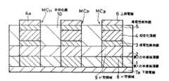
図2はメモリセルアレイの一部を示す平面図、図3は図2のIII−III線に沿っての断面図、図4は図2のIV−IV線に沿っての断面図、図5は図2のV−V線に沿っての断面図である。
【0021】
図2、図3、図4および図5に示すように、第1の半導体薄膜1および第2の半導体薄膜2が積層された一方の面上に、選択的に設けられた導電性断熱膜3、相変化薄膜4および導電性断熱膜5を介して、上部電極6が互いに平行に延在して設けられている。第1の半導体薄膜1の他方の面上に下部電極7が互いに平行に延在して設けられている。上部電極6と下部電極7とは、それらの長手方向がそれぞれ互いに直交するように設けられている。上部電極6と下部電極7とが平面的に交差する部分の第1の半導体薄膜1には、選択的にn+型領域8が設けられている。また、上部電極6と下部電極7とが平面的に交差する部分の第2の半導体薄膜2には、選択的にp+型領域9が設けられている。これらのn+型領域8とp+型領域9とによりnp接合が構成されている。このnp接合は、相変化薄膜4に電圧を印加する際のスイッチ素子となる。
【0022】
第1の半導体薄膜1および第2の半導体薄膜2は、例えば多結晶Siからなる。相変化薄膜4は、例えば酸化バナジウム(V2O5)や、GeTeSbなどのカルコゲナイド半導体などからなり、この第1の実施形態においては、例えば膜厚が5nmのV2O5膜からなる。このV2O5は、比抵抗が4.9Ω・cmとなる状態の「低温相」と、比抵抗が7Ω・cmとなる状態の「高温相」との2つの安定相を有する。
【0023】
また、上部電極6および下部電極7は、電気抵抗が低くなければならないため、アルミニウム(Al)、銅(Cu)などの金属からなる。これらのAl、Cuなどからなる金属膜は一般に熱伝導率が高いために、また、相変化薄膜4に効率よく電流を流すとともにこの相変化薄膜4において生じた熱の拡散を最小限に抑えるために、導電性断熱膜3、5は相変化薄膜4におけるよりも電気抵抗が低く、かつ低熱伝導率の材料からなる。具体的には、導電性断熱材3、5は、例えばITO(Indium Tin Oxide)、酸化亜鉛(ZnO)などの導電性酸化物からなり、この第1の実施形態においては、例えばITOからなる。
【0024】
次に、上述のように構成されたこの第1の実施形態による不揮発性メモリの製造方法の一例を図3に示す断面図に相当する断面図である図6および図7を参照して説明する。
【0025】
まず、図6Aに示すように、支持基板11上にAl、Cuなどを成膜した後、、この膜をエッチングにより所定形状にパターンニングして、下部電極7を形成する。次に、下部電極7の凹部を平坦化膜(いずれも図示せず)で埋め込み、表面を平坦化する。次に、このようにして平坦化された表面に、例えば多結晶Siからなる第1の半導体薄膜1を成膜する。その後、第1の半導体薄膜1に、例えばレジストパターン(図示せず)をマスクとしてn型不純物を選択的にイオン注入し、n+型領域8を形成する。次に、第1の半導体薄膜1上に第2の半導体薄膜2を成膜する。その後、n+型領域8上の第2の半導体薄膜2の部分に、例えばレジストパターン(図示せず)をマスクとして選択的にp型不純物を導入して、p+型領域9を形成する。
【0026】
次に、図6Bに示すように、第2の半導体薄膜2上にITO、V2O5およびITOを順次成膜することにより、ITOからなる導電性断熱膜3、V2O5からなる相変化薄膜4およびITOからなる導電性断熱膜5が順次積層された積層膜を形成する。
【0027】
次に、図6Cに示すように、導電性断熱膜3、相変化膜4および導電性断熱膜5を、平面の寸法が例えば0.5×0.5μmとなる複数のメモリセル形状にパターンニングする。
【0028】
次に、図7Aに示すように、パターンニングされた導電性断熱膜3、相変化膜4および導電性断熱膜5からなる積層膜の凹部を平坦化膜10で埋め込み、表面を平坦化する。
【0029】
次に、図7Bに示すように、このようにして平坦化された表面に、Al、Cuなどの金属膜を成膜した後、この膜をエッチングによりパターンニングして上部電極6を形成する。
【0030】
その後、支持基板11および下部電極7の凹部に埋め込まれた平坦化膜(図示せず)を除去する。これによって図2、図3、図4および図5に示すように、目的とする不揮発性メモリが製造される。
【0031】
次に、この第1の実施形態による不揮発性メモリの消去、書き込みおよび読み出しを行う方法について説明する。
【0032】
まず、消去について、後述のように書き込みは、上部電極6および下部電極7によって印加される電圧によるダイレクトオーバーライトが可能であるため、特別の消去過程を必要としない。
【0033】
次に、書き込みについて説明する。ここで、np接合からなるスイッチ素子を接続せずに、相変化薄膜4の相を「低温相」から「高温相」に変化させるために必要な電圧をVhとし、「高温相」から「低温相」に変化させるために必要な電圧をVlとすると、
Vl<Vh
の関係が成立する。
【0034】
また、図8に示すように、np接合においては、順方向バイアスをかけた場合には低抵抗であるが、逆方向バイアスをかけた場合には、降伏電圧Vbまでは高抵抗であり、降伏電圧Vb以上では低抵抗となる。そのため、相変化薄膜4にnp接合を直列に接続して、上部電極6と下部電極7との間でnp接合に対して逆方向バイアスを印加する場合、相変化薄膜4に電圧を印加するためには、上部電極6と下部電極7との間の電圧を絶対値において降伏電圧Vbより高い電圧にする必要がある。
【0035】
そして、選択されたメモリセルに印加された電圧が十分高く、この電圧がVb+Vh(相変化薄膜4が「低温相」)、またはVb+Vl(相変化薄膜4が「高温相」)より高い場合には、相変化薄膜4中に相の変化を起こすのに十分な電流が流れ、電力が供給されて加熱される。この加熱により、相変化薄膜4の相が「高温相」から「低温相」、または「低温相」から「高温相」に変化する。このように、電流によって相変化薄膜4の加熱温度を調整することにより、相の状態を制御する。
【0036】
このような、電流による相の制御に基づいて、書き込みはランダムに行うことが可能である。ここで、相変化薄膜4の相が「高温相」である場合をデータ「1」とし、「低温相」である場合をデータ「0」とする。
【0037】
一例として、選択されたメモリセルMC11に、np接合に対して逆方向バイアスに電圧を印加してデータ「1」を書き込む場合を考える(逆方向書き込み)。この場合、選択されたメモリセルMC11に重なる上部電極6aに(Vb+Vh)/2を印加し、下部電極7aに−(Vb+Vh)/2を印加する。また、メモリセルMC11に重ならない上部電極6および下部電極7は0Vに接地しておく。また、(Vb+Vh)/2に印加された上部電極6aに重なる、選択されたメモリセル以外のメモリセルMCi1(i=2、3、・・・、n)に電流が流れるのを防止するためには、
(Vb+Vh)/2<Vb
すなわち、
Vh<Vb
の関係が成立する必要がある。同様に、下部電極7aに重なる、選択されたメモリセルMC11以外のメモリセルMC1j(j=2、3、・・・、m)に電流が流れるのを防止するためには、
−(Vb+Vh)/2>−Vb
すなわち、
Vh<Vb
の関係が成立する必要がある。これらの条件は、相変化薄膜4に用いられる材料、相変化薄膜4の膜厚およびパターン寸法を最適化したり、pn接合を構成するp+型領域9およびn+型領域8における不純物のドープ量を最適化したりすることにより、容易に実現可能な条件である。
【0038】
この第1の実施形態においては、相変化薄膜4をV2O5から構成し、その膜厚を5nm、平面の寸法を0.5μm×0.5μmとする。これにより、相変化薄膜4が「低温相」の状態のときの抵抗値が980Ωとなり、「高温相」の状態のときの抵抗値が1400Ωとなる。また、相変化薄膜4を「低温相」から「高温相」に変化させるために必要な電力は50mWであり、「高温相」から「低温相」に変化させるために必要な電力は24mWである。また、この第1の実施形態におけるnp接合においては、降伏電圧Vbは8Vであり、8V未満の範囲にあっては、逆方向バイアスの印加によって10-13Aの電流が流れる(図9参照)。
【0039】
すなわち、この第1の実施形態において、選択されたメモリセルMC11にデータ「1」を書き込むために、メモリセルMC11の相変化薄膜4を「低温相」から「高温相」に変化させる場合、上部電極6aを−7.5Vに印加し、下部電極7を7.5Vに印加して、np接合に対して逆方向バイアスを印加する。これにより、相変化薄膜4には(7.5−(−7.5)−8=)7Vの電圧が印加される。このとき、「低温相」の相変化薄膜4には、
7V×7V/980Ω=0.05W=50mW
の電力が供給される。これにより、相変化薄膜4が「低温相」から「高温相」に変化して、メモリセルMC11にデータ「1」の書き込みが行われる。なお、メモリセルMC11にデータ「1」がすでに書き込まれており、この相変化薄膜4の相が「高温相」の場合には、メモリセルMC11へのデータ「1」の書き込みは行わない。
【0040】
また、電圧が印加された上部電極6aに重なる、選択されたメモリセルMC11以外のメモリセルMCi1(i=2、3、・・・、n)には、電圧が7.5Vの逆方向バイアスが印加される。このとき、メモリセルMCi1のnp接合に流れる電流は10-13Aとなり、相変化薄膜4に供給される電力は、
(10-13A)2×980Ω≒1×10-24W
となる。この電力値は、相を変化させることができる電力(50mW)よりはるかに小さいため、相の変化は起こらず、メモリセルMCi1への書き込みが防止される。同様に、下部電極7aに重なる、選択されたメモリセルMC11以外のメモリセルMC1j(j=2、3、・・・、m)にも、電圧が7.5Vの逆方向バイアスが印加されるので、同様の電流が流れ、このメモリセルMC1jの相変化薄膜4に供給される電力も、1×10-24Wとなる。これにより、メモリセルMC1jへの書き込みも防止される。
【0041】
次に、選択されたメモリセルMC11に、np接合に対して逆方向バイアスを印加してデータ「0」を書き込む場合を考える(逆方向書き込み)。この場合、選択されたメモリセルMC11に重なる上部電極6aに(Vb+Vl)/2を印加し、下部電極7aに−(Vb+Vl)/2を印加する。メモリセルMC11に重ならない上部電極6および下部電極7は0Vに接地しておく。(Vb+Vl)/2に印加された上部電極6aに重なる、選択されたメモリセル以外のメモリセルMCi1(i=2、3、・・・、n)に電流が流れるのを防止するためには、「低温相」から「高温相」の場合におけると同様に、
Vl<Vb
の関係が成立する必要がある。また、下部電極7aに重なる、選択されたメモリセルMC11以外のメモリセルMC1j(j=2、3、・・・、m)に電流が流れるのを防止する場合においても、
Vl<Vb
の関係が成立する必要がある。これらの条件は、相変化薄膜4に用いられる材料、膜厚あるいはパターン寸法を最適化したり、pn接合を形成するn+型領域9およびp+型領域8中の不純物のドープ量を最適化することにより、容易に達成可能な条件である。
【0042】
また、この第1の実施形態において、選択されたメモリセルMC11にデータ「0」を書き込むために、メモリセルMC11の相変化薄膜4を「高温相」から「低温相」に変化させる場合、上部電極6aを−6.9Vに印加し下部電極7を6.9Vに印加する。これにより、np接合に対して逆方向バイアスが印加され、相変化薄膜4には、
(6.9V−(−6.9V)−8V=)5.8V
の電圧が印加される。このとき、「高温相」の相変化薄膜4には、
5.8V×5.8V/1400Ω≒0.024W=24mW
の電力が供給される。これにより、相変化薄膜4の相が「高温相」から「低温相」に変化して、メモリセルMC11にデータ「0」の書き込みが行われる。なお、メモリセルMC11にデータ「0」がすでに書き込まれており、この相変化薄膜4が「低温相」の場合には、メモリセルMC11へのデータ「0」の書き込みは行わない。
【0043】
次に、選択されたメモリセルMC11に、np接合に順方向バイアスを印加してデータ「1」を書き込む場合を考える(順方向書き込み)。この場合、上部電極6と下部電極7との間で印加される電圧は、そのまま相変化薄膜4に印加される。そのため、相変化薄膜4の相を「低温相」から「高温相」に変化させる場合には、上部電極6aにVh/2を印加し、下部電極7aに−Vh/2を印加する。これにより、相変化薄膜4にはVhの電圧が印加され、その相が「低温相」から「高温相」に変化する。同様に、相変化薄膜4の相を「高温相」から「低温相」に変化させる場合には、上部電極6aにVl/2を印加し、下部電極7aに−Vl/2を印加する。
【0044】
また、上述したように、この第1の実施形態においては、相変化薄膜4が「低温相」のときはその抵抗値が980Ωとなり、「高温相」のときはその抵抗値が1400Ωとなる。また、相変化薄膜4を「低温相」から「高温相」に変化させるのに50mWの電力を要し、「高温相」から「低温相」に変化させるのに24mWの電力を要する。そのため、相変化薄膜4が「低温相」であるメモリセルMC11にデータ「1」を書き込む場合、上部電極6aに(−7/2=)−3.5Vを印加し下部電極7aに(7/2=)3.5Vを印加することで、相変化薄膜4に7Vの電圧を印加する。この電圧の印加によって相変化薄膜4には、
7V×7V/980Ω=0.05W=50mW
の電力が供給される。これにより、相変化薄膜4の相が「低温相」から「高温相」に変化し、メモリセルMC11にデータ「1」が書き込まれる。また、電圧が印加された上部電極6aに重なる、選択されたメモリセルMC11以外のメモリセルMCi1(i=2、3、・・・、n)には、電圧が3.5Vの順方向バイアスが印加される。このとき、相変化薄膜4に供給される電力は、
3.5V×3.5V/980Ω=0.0125W
=12.5mW(<50mW)
となる。この電力値は、相を変化させることができる電力(50mW)未満であるため、相の変化は起こらず、メモリセルMCi1への書き込みは防止される。同様に、下部電極7aに重なる、選択されたメモリセルMC11以外のメモリセルMC1j(j=2、3、・・・、m)にも、電圧が3.5Vの順方向バイアスが印加されるので、同様の電流が流れる。これによって、メモリセルMC1jの相変化薄膜4に供給される電力は12.5mWとなり、メモリセルMC1jへの書き込みも防止される。
【0045】
また、メモリセルMC11にデータ「0」を書き込む場合、上部電極6aに(−5.8V/2=)−2.9Vを印加し、下部電極7aに(5.8V/2=)2.9Vを印加して、相変化薄膜4に5.8Vの電圧を印加する。この電圧の印加によって相変化薄膜4には
5.8V×5.8V/1400Ω=0.024W
=24mW
の電力が供給される。これにより、相変化薄膜4の相が「高温相」から「低温相」に変化し、メモリセルMC11にデータ「0」が書き込まれる。また、電圧が印加された上部電極6aに重なる、選択されたメモリセルMC11以外のメモリセルMCi1(i=2、3、・・・、n)には、np接合に対して、電圧が2.9Vの順方向バイアスが印加される。このとき、「高温相」の相変化薄膜4に供給される電力は、
2.9V×2.9V/1400Ω≒0.006W
=6mW
となる。この電力値は、相を変化させることができる電力(24mW)未満であるため、相の変化は起こらず、メモリセルMCi1への書き込みは防止される。同様に、下部電極7aに重なる、選択されたメモリセルMC11以外のメモリセルMC1j(j=2、3、・・・、m)にも、np接合の順方向バイアスの向きに2.9Vの電圧が印加されるので、同様の電流が流れる。これにより、メモリセルMC1jの相変化薄膜4に供給される電力は6mWに抑えられ、メモリセルMC1jへの書き込みも防止される。
【0046】
以上のようにして書き込みを行うことにより、ダイレクトオーバーライトが可能となり、ディスターブの少ない書き込みを行うことができる。
【0047】
読み出しは次のようにして行う。すなわち、例えばメモリセルMC11のデータを読み出す場合には、メモリセルMC11に重なる上部電極6aにVb/2と(Vb+Vl)/2との間の電圧を印加するとともに、下部電極7aに−(Vb+Vl)/2と−Vb/2との間の電圧を印加する。また、上部電極6a以外の上部電極6の電圧と、下部電極7a以外の下部電極7の電圧とを0Vに接地する。これによって、選択されたメモリセルMC11にのみ電流が流れ、メモリセルMC11以外のメモリセルMCijには電流が流れない。
【0048】
また、上部電極6aと下部電極7aとの間には、スイッチ素子としてのnp接合に対して、電圧がVb以上(Vb+Vl)未満の範囲で逆方向バイアスが印加される。そのため、相変化薄膜4に印加される電圧は0以上Vl未満の範囲となるので、相変化薄膜4の相状態は影響を受けず相変化することがない。これにより、メモリセルMC11の記録状態は維持される。
【0049】
具体的には、この第1の実施形態においては、上部電極6aに−5Vの電圧を印加し、下部電極7aに5Vの電圧を印加する。このとき、メモリセルMC11には、電圧が10Vのnp接合に対して逆方向バイアスが印加される。np接合の降伏電圧Vbが8Vであることから、相変化薄膜4には、(10−8=)2Vの電圧が印加される。そのため、相変化薄膜4中を流れる電流が、
2V/980Ω≒0.002A=2mA
となる場合に、相変化薄膜4が「低温相」であり、書き込まれたデータがデータ「0」として読み出される。このとき、相変化薄膜4に供給される電力は、
2V×2V/980Ω≒0.004W=4mW
である。この電力値は、相変化薄膜4の相を変化させることができる電力未満であるため、相変化薄膜4の相は変化せず、記憶状態は維持される。また、上部電極6aおよび下部電極7aのいずれか一方に平面的に重なる、メモリセルMC11以外のメモリセルMCi1、MC1jには、電圧が高々5Vの逆方向バイアスが印加されるので、そこに流れる電流は、1×10-13A(図9参照)となる。したがって、読み出し時に流れる電流において、メモリセルMCi1、MC1jに対するメモリセルMC11の選択比は2×10¹⁰となる。これにより、クロストークの発生が防止される。
【0050】
他方、相変化薄膜4中を流れる電流が、
2V/1400Ω≒0.0014A=1.4mA
程度になる場合、相変化薄膜4は「高温相」であると認識され、書き込まれたデータがデータ「1」として読み出される。このとき、相変化薄膜4に供給される電力は、
2V×2V/1400Ω≒0.0028W=2.8mW
である。この電力値は、相変化薄膜4の相を変化させることができる電力未満であるため、相変化薄膜4の相は変化せず、記憶状態は維持される。また、上部電極6aおよび下部電極7aのいずれか一方のみに平面的に重なる、メモリセルMC11以外のメモリセルMC1j、MCi1には、電圧が高々5Vの逆方向バイアスが印加されるので、そこに流れる電流は、1×10-13A(図9参照)となる。したがって、読み出し時に流れる電流において、メモリセルMC1j、MCi1に対するメモリセルMC11の選択比は、1.4×10¹⁰となる。これにより、クロストークが防止される。
【0051】
以下同様にしてそれぞれのメモリセルのデータを読み出すことができる。このように、読み出し時にもランダムアクセスが可能である。
【0052】
以上説明したように、この第1の実施形態によれば、「高温相」と「低温相」との室温において安定した2つの相を有する相変化薄膜4と、この相変化薄膜4に直列に接続されたpn接合からなるスイッチ素子とからなるメモリセルを複数設けて不揮発性メモリを構成していることにより、相変化薄膜4に流れる電流をpn接合により制御することができるとともに、この電流により相変化薄膜4を「高温相」と「低温相」とで相互に変化させることができる。そして、この相変化薄膜4の相を変化させ、その抵抗値を変化させることによって、データの書き込みを行うことが可能となり、また、相変化薄膜4の相の違いによる抵抗値の違いに応じた電流値を調べることでデータの読み出しを行うことが可能となる。これによって、2端子のメモリセルを用いた不揮発性メモリにおいて、ディスターブやクロストークの問題が生じることなく、読み出しや書き込みなどのランダムアクセスが可能になるとともに、メモリセルの構造を単純化することができるので、不揮発性メモリにおける高速化、高集積化および低コスト化を図ることができる。
【0053】
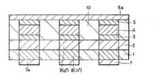
また、この第1の実施形態による不揮発性メモリを構成するメモリセルは、従来の強誘電体メモリやフラッシュメモリのように、単結晶Siなどを用いたMOSトランジスタを使用していない。これにより、3次元構造化を容易に実現することができる。この3次元構造化された不揮発性メモリについて、以下のこの発明の第2の実施形態において説明する。なお、図10はこの積層構造の不揮発性メモリを示す断面図で、図3に相当する断面図である。
【0054】
図10に示すように、この第2の実施形態による不揮発性メモリは、第1の実施形態による不揮発性メモリを2層積層することにより構成されている。より具体的には、この第2の実施形態による不揮発性メモリは、図3に示す不揮発性メモリ(第1層目)上に同様な不揮発性メモリ(第2層目)を積層したものである。各層間には層間絶縁膜は不要である。第1層目の不揮発性メモリにおける上部電極と第2層目の不揮発性メモリの下部電極とは、共通電極11として共通に用いられる。この共通電極12はストライプ形状を有し、この共通電極12のストライプ間は平坦化膜13により埋められている。
【0055】
この第2の実施形態によれば、第1の実施形態と同様の効果を得ることができるとともに、積層化により、集積度の飛躍的な向上を図ることができるという、さらなる効果を得ることができる。
【0056】
以上、この発明の実施形態について具体的に説明したが、この発明は、上述の実施形態に限定されるものではなく、この発明の技術的思想に基づく各種の変形が可能である。
【0057】
例えば、上述の実施形態において挙げた数値、構造、形状、材料、プロセスなどはあくまでも例に過ぎず、必要に応じて、これと異なる数値、構造、形状、材料、プロセスなどを用いることが可能である。
【0058】
また、上述の第1の実施形態で説明した不揮発性メモリの製造方法は一例に過ぎず、これと異なる製造方法を用いてもよい。
【0059】
また、上述の第1の実施形態においては、相変化薄膜4が「高温相」のときをデータ「1」とし、「低温相」のときをデータ「0」としたが、これらの対応関係は逆にしてもよい。すなわち、相変化薄膜4が「高温相」のときをデータ「0」とし、「低温相」のときをデータ「1」としてもよい。
【0060】
また、上述の第1の実施形態においては、n+型領域8とp+型領域9とからなるnp接合のn+型領域8を下部電極7に接続するようにしているが、n+型領域とp+型領域との接合をpn接合とし、p+型領域を下部電極7に接続することも可能である。
【0061】
また、上述の第1の実施形態においては、np接合を下部電極7側に設け、相変化薄膜4を上部電極6側に設けるようにしているが、np接合またはpn接合を上部電極6側に設け、相変化薄膜4を下部電極7側に設けて、積層の順序を反対にすることも可能である。
【0062】
【発明の効果】
以上説明したように、この発明によれば、不揮発性メモリが、室温下において少なくとも2つ以上の安定相を有する相変化薄膜と、この相変化薄膜に接続されたスイッチ素子とからなるメモリセルから構成されていることにより、2端子の簡単な構造のメモリセルで、消去、書き込みおよび読み出しが可能となり、しかもディスターブが少なく、高集積で、高密度記録が可能な不揮発性メモリを実現することができる。
【図面の簡単な説明】
【図1】この発明の第1の実施形態による不揮発性メモリを示す回路図である。
【図2】この発明の第1の実施形態による不揮発性メモリのメモリセルアレイの一部の構造例を示す平面図である。
【図3】図2のIII−III線に沿っての断面図である。
【図4】図2のIV−IV線に沿っての断面図である。
【図5】図2のV−V線に沿っての断面図である。
【図6】この発明の第1の実施形態による不揮発性メモリの製造方法の一例を説明するための断面図である。
【図7】この発明の第1の実施形態による不揮発性メモリの製造方法の一例を説明するための断面図である。
【図8】この発明の第1の実施形態によるnp接合の電流−電圧特性を示すグラフである。
【図9】この発明の第1の実施形態によるnp接合に逆方向バイアスを印加した場合に流れる電流の印加電圧依存性を示すグラフである。
【図10】この発明の第2の実施形態による積層構造の不揮発性メモリの一例を示す断面図である。
【符号の説明】
1・・・第1の半導体薄膜、2・・・第2の半導体薄膜、3、5・・・導電性断熱膜、4・・・相変化薄膜、6・・・上部電極、7・・・下部電極、8・・・n+型領域、9・・・p+型領域、MC11〜MC1j、MC11〜MCi1・・・メモリセル[0001]
BACKGROUND OF THE INVENTION
The present invention relates to a nonvolatile memory and a driving method thereof.
[0002]
[Prior art]
As nonvolatile solid-state memories, flash memories, FeRAMs, and the like are known. All of these require three to four terminals for one information recording cell. Thus, when there are many terminals connected to one cell, a wiring space is required, and the degree of integration becomes low. That is, when high integration is considered, it is necessary to read the record with a simpler cell with a small number of terminals.
[0003]
For the purpose of such high-density information recording, the smaller the number of terminals connected to the cell, the more advantageous. For example, when considering access in a solid-state memory, the number of terminals has a lower limit of 2 terminals.
[0004]
[Problems to be solved by the invention]
However, in the conventional memory, when the number of terminals is two, not only the disturb problem of affecting the cells other than the selected cell at the time of writing occurs, but also writing and reading are performed. There was a problem of being unable to achieve both.
[0005]
Accordingly, an object of the present invention is to provide a nonvolatile memory capable of erasing, writing, and reading data, simplifying the structure of the memory cell, and enabling high-density information recording, and a driving method thereof. It is in.
[0006]
[Means for Solving the Problems]
In order to achieve the above object, the first invention of the present invention provides:
A memory cell comprising a phase change thin film having at least two stable phases at room temperature and a switch element connected in series to the phase change thin film
This is a non-volatile memory.
[0007]
In the first aspect of the present invention, typically, the phase of the phase change thin film is configured to change by applying a voltage higher than the threshold voltage of the switching element to the memory cell to flow a current. The nonvolatile memory according to the first aspect of the invention is configured so that information can be written into the memory cell by changing the phase of the phase change thin film.
[0008]
In the first aspect of the invention, typically, the electric resistances of the phase change thin films are different from each other in accordance with the phase state of the phase change thin film. Preferably, the memory cell is configured to be able to read information from the memory cell based on a difference in current flowing in the phase change thin film by applying a voltage higher than the threshold voltage of the switching element to the memory cell. ing.
[0009]
In the first aspect of the invention, the nonvolatile memory typically includes a lower electrode arranged in a stripe shape and an upper portion arranged in a stripe shape and having a longitudinal direction substantially perpendicular to the longitudinal direction of the lower electrode. And an upper electrode and a lower electrode so that a voltage can be applied to the memory cell. Preferably, a memory cell is provided between the upper electrode and the lower electrode at a portion where the lower electrode and the upper electrode intersect.
[0010]
In the first aspect of the present invention, it preferably includes a lower electrode arranged in a stripe shape, and an upper electrode arranged in a stripe shape in a longitudinal direction perpendicular to the longitudinal direction of the lower electrode. A non-volatile memory configured such that a voltage can be applied to a memory cell by an electrode and a lower electrode has a stacked structure in which a plurality of stacked non-volatile memories are stacked. In the nonvolatile memory having this stacked structure, the upper electrode in the first nonvolatile memory is used as the lower electrode in the second nonvolatile memory stacked on the upper layer of the first nonvolatile memory.
[0011]
In the first aspect of the invention, the switch element typically includes a pn junction or an np junction. In the first invention, the switch element typically has a pn junction or an np junction composed of a p-type semiconductor thin film and an n-type semiconductor thin film. Specifically, the switch element is composed of an np junction or a pn junction composed of a p-type silicon thin film and an n-type silicon thin film. In the first invention, when an np junction is used as a switch element and a reverse bias is applied to the np junction, the threshold voltage of the switch element is a breakdown voltage.
[0012]
In the first aspect of the invention, typically, an element whose electric resistance is lowered when a voltage equal to or higher than a threshold voltage is applied as the switch element. In order to perform writing of information to the nonvolatile memory with good controllability, an element whose electrical resistance is drastically reduced by applying a voltage higher than a threshold voltage is used as a switching element.
[0013]
The second invention of this invention is:
A memory cell comprising a phase change thin film having at least two stable phases at room temperature, and a switch element connected in series to the phase change thin film;
A method of driving a nonvolatile memory having an upper electrode and a lower electrode configured to be able to apply a voltage to a memory cell,
When writing, a voltage higher than the sum of the threshold voltage of the switch element and the phase changeable voltage of the phase change thin film is applied between the upper electrode and the lower electrode connected to the selected memory cell. Write data by changing the phase of the phase change thin film in the selected memory cell,
During reading, a voltage that is equal to or higher than the threshold voltage and less than the total voltage of the threshold voltage and the phase changeable voltage is applied between the upper electrode and the lower electrode connected to the selected memory cell. Data by reading the phase state of the phase change thin film
It is characterized by this.
[0014]
Note that Japanese Patent No. 2743980 and Japanese Patent No. 2806660 propose a method of writing information by a simpler method without using a transistor. However, these methods only describe a reading method. In addition, there is no description on how to prevent the disturb problem at the time of writing and reading.
[0015]
According to the nonvolatile memory of the present invention configured as described above, a memory cell including a phase change thin film having at least two or more stable phases at room temperature and a switch element connected to the phase change thin film is provided. By having this, the current flowing in the phase change thin film can be controlled by using a switch element, and this current can change the phase of the phase change thin film and read the state of the phase. it can.
[0016]
DETAILED DESCRIPTION OF THE INVENTION
Hereinafter, embodiments of the present invention will be described with reference to the drawings. In all the drawings of the embodiments, the same or corresponding parts are denoted by the same reference numerals.
[0017]
FIG. 1 is a circuit diagram of a memory cell array of a nonvolatile semiconductor memory according to a first embodiment of the present invention.
[0018]
As shown in FIG. 1, in the nonvolatile memory according to the first embodiment, memory cells configured by connecting pn diodes and capacitors in series are arranged in a matrix. One end of the capacitor is the bit line Bi(I = 1 to n) and the other end is connected to the p-side electrode of the pn diode. The n-side electrode of the pn diode is a word line W.j(J = 1 to m).
[0019]
Next, a specific structural example of the nonvolatile memory according to the first embodiment will be described.
[0020]
2 is a plan view showing a part of the memory cell array, FIG. 3 is a cross-sectional view taken along line III-III in FIG. 2, FIG. 4 is a cross-sectional view taken along line IV-IV in FIG. It is sectional drawing along the VV line of FIG.
[0021]
As shown in FIGS. 2, 3, 4, and 5, a conductive
[0022]
The first semiconductor
[0023]
The
[0024]
Next, an example of a method of manufacturing the nonvolatile memory according to the first embodiment configured as described above will be described with reference to FIGS. 6 and 7 which are sectional views corresponding to the sectional view shown in FIG. .
[0025]
First, as shown in FIG. 6A, after depositing Al, Cu, or the like on the
[0026]
Next, as shown in FIG. 6B, on the second semiconductor
[0027]
Next, as shown in FIG. 6C, the conductive
[0028]
Next, as shown in FIG. 7A, the concave portion of the laminated film composed of the patterned conductive
[0029]
Next, as shown in FIG. 7B, a metal film made of Al, Cu or the like is formed on the surface flattened in this manner, and then the
[0030]
Thereafter, the planarizing film (not shown) embedded in the concave portions of the
[0031]
Next, a method for erasing, writing, and reading from the nonvolatile memory according to the first embodiment will be described.
[0032]
First, with regard to erasure, writing, as described later, does not require a special erasing process because direct overwriting by a voltage applied by the
[0033]
Next, writing will be described. Here, the voltage required to change the phase of the phase change
Vl<Vh
The relationship is established.
[0034]
In addition, as shown in FIG. 8, in the np junction, when the forward bias is applied, the resistance is low, but when the reverse bias is applied, the breakdown voltage VbUp to high resistance, breakdown voltage VbAbove, it becomes low resistance. Therefore, when an np junction is connected in series to the phase change
[0035]
The voltage applied to the selected memory cell is sufficiently high and this voltage is Vb+ Vh(Phase change
[0036]
Based on such phase control by current, writing can be performed randomly. Here, a case where the phase of the phase change
[0037]
As an example, the selected memory cell MC11Consider the case where data “1” is written by applying a reverse bias voltage to the np junction (reverse writing). In this case, the selected memory cell MC11(Vb+ Vh) / 2 is applied, and-(Vb+ Vh) / 2 is applied. In addition, the memory cell MC11The
(Vb+ Vh) / 2 <Vb
That is,
Vh<Vb
The relationship needs to be established. Similarly, the selected memory cell MC overlapping the
-(Vb+ Vh) / 2> -Vb
That is,
Vh<Vb
The relationship needs to be established. These conditions are such that the material used for the phase change
[0038]
In the first embodiment, the phase change
[0039]
That is, in the first embodiment, the selected memory cell MC11In order to write data “1” into the memory cell MC11When the phase change
7V × 7V / 980Ω = 0.05W = 50mW
Power is supplied. As a result, the phase change
[0040]
The selected memory cell MC that overlaps the
(10-13A)2× 980Ω ≒ 1 × 10-twenty fourW
It becomes. This power value is much smaller than the power that can change the phase (50 mW), so no phase change occurs and the memory cell MCi1Writing to is prevented. Similarly, the selected memory cell MC overlapping the
[0041]
Next, the selected memory cell MC11Consider the case where data “0” is written by applying a reverse bias to the np junction (reverse writing). In this case, the selected memory cell MC11(Vb+ Vl) / 2 is applied, and-(Vb+ Vl) / 2 is applied. Memory cell MC11The
Vl<Vb
The relationship needs to be established. The selected memory cell MC overlapping the
Vl<Vb
The relationship needs to be established. These conditions are such that the material, film thickness, or pattern size used for the phase change
[0042]
In the first embodiment, the selected memory cell MC11In order to write data “0” to the memory cell MC11When the phase change
(6.9V-(-6.9V) -8V =) 5.8V
Is applied. At this time, the phase change
5.8V × 5.8V / 1400Ω≈0.024W = 24mW
Power is supplied. As a result, the phase of the phase change
[0043]
Next, the selected memory cell MC11Consider a case where data “1” is written by applying a forward bias to the np junction (forward writing). In this case, the voltage applied between the
[0044]
As described above, in the first embodiment, when the phase change
7V × 7V / 980Ω = 0.05W = 50mW
Power is supplied. As a result, the phase of the phase change
3.5V × 3.5V / 980Ω = 0.0125W
= 12.5mW (<50mW)
It becomes. Since this power value is less than the power that can change the phase (50 mW), the phase change does not occur and the memory cell MCi1Writing to is prevented. Similarly, the selected memory cell MC overlapping the
[0045]
In addition, the memory cell MC11When data “0” is written to the
5.8V × 5.8V / 1400Ω = 0.024W
= 24mW
Power is supplied. As a result, the phase of the phase change
2.9V × 2.9V / 1400Ω ≒ 0.006W
= 6mW
It becomes. Since this power value is less than the power that can change the phase (24 mW), the phase change does not occur and the memory cell MCi1Writing to is prevented. Similarly, the selected memory cell MC overlapping the
[0046]
By performing writing as described above, direct overwriting becomes possible, and writing with less disturbance can be performed.
[0047]
Reading is performed as follows. That is, for example, the memory cell MC11When reading the data of memory cell MC11V on the
[0048]
In addition, between the
[0049]
Specifically, in the first embodiment, a voltage of -5V is applied to the
2V / 980Ω ≒ 0.002A = 2mA
In this case, the phase change
2V × 2V / 980Ω ≒ 0.004W = 4mW
It is. Since this power value is less than the power that can change the phase of the phase change
[0050]
On the other hand, the current flowing through the phase change
2V / 1400Ω ≒ 0.0014A = 1.4mA
In the case, the phase change
2V × 2V / 1400Ω ≒ 0.0028W = 2.8mW
It is. Since this power value is less than the power that can change the phase of the phase change
[0051]
In the same manner, the data of each memory cell can be read out. In this way, random access is possible even during reading.
[0052]
As described above, according to the first embodiment, the phase change
[0053]
Further, the memory cell constituting the nonvolatile memory according to the first embodiment does not use a MOS transistor using single crystal Si or the like, unlike the conventional ferroelectric memory and flash memory. Thereby, three-dimensional structuring can be easily realized. This three-dimensional structured nonvolatile memory will be described in the second embodiment of the present invention below. FIG. 10 is a cross-sectional view showing the non-volatile memory having this stacked structure, and is a cross-sectional view corresponding to FIG.
[0054]
As shown in FIG. 10, the nonvolatile memory according to the second embodiment is formed by stacking two layers of the nonvolatile memory according to the first embodiment. More specifically, the nonvolatile memory according to the second embodiment is obtained by stacking a similar nonvolatile memory (second layer) on the nonvolatile memory (first layer) shown in FIG. . An interlayer insulating film is not required between the layers. The upper electrode in the first layer nonvolatile memory and the lower electrode in the second layer nonvolatile memory are commonly used as the
[0055]
According to the second embodiment, the same effect as that of the first embodiment can be obtained, and a further effect that the degree of integration can be drastically improved by stacking can be obtained. it can.
[0056]
As mentioned above, although embodiment of this invention was described concretely, this invention is not limited to the above-mentioned embodiment, The various deformation | transformation based on the technical idea of this invention is possible.
[0057]
For example, the numerical values, structures, shapes, materials, processes, and the like given in the above-described embodiments are merely examples, and different numerical values, structures, shapes, materials, processes, and the like can be used as necessary. is there.
[0058]
Further, the method of manufacturing the nonvolatile memory described in the first embodiment is merely an example, and a manufacturing method different from this may be used.
[0059]
In the first embodiment described above, when the phase change
[0060]
In the first embodiment described above, n+Type region 8 and p+Np junction n consisting of the
[0061]
In the first embodiment described above, the np junction is provided on the
[0062]
【The invention's effect】
As described above, according to the present invention, a nonvolatile memory includes a memory cell including a phase change thin film having at least two stable phases at room temperature and a switch element connected to the phase change thin film. By being configured, it is possible to realize a non-volatile memory capable of erasing, writing and reading with a memory cell having a simple structure of two terminals, with less disturbance, high integration, and high density recording. it can.
[Brief description of the drawings]
FIG. 1 is a circuit diagram showing a nonvolatile memory according to a first embodiment of the present invention.
FIG. 2 is a plan view showing a structural example of a part of the memory cell array of the nonvolatile memory according to the first embodiment of the invention.
FIG. 3 is a cross-sectional view taken along line III-III in FIG.
4 is a cross-sectional view taken along line IV-IV in FIG.
5 is a cross-sectional view taken along line VV in FIG.
FIG. 6 is a cross-sectional view for explaining an example of the method for manufacturing the nonvolatile memory according to the first embodiment of the present invention.
FIG. 7 is a cross-sectional view for explaining an example of the method for manufacturing the nonvolatile memory according to the first embodiment of the present invention.
FIG. 8 is a graph showing current-voltage characteristics of the np junction according to the first embodiment of the present invention.
FIG. 9 is a graph showing the applied voltage dependence of the current that flows when a reverse bias is applied to the np junction according to the first embodiment of the present invention;
FIG. 10 is a cross-sectional view showing an example of a non-volatile memory having a stacked structure according to a second embodiment of the present invention.
[Explanation of symbols]
DESCRIPTION OF
Claims (3)
Translated fromJapanese書き込み時には、選択されたメモリセルに接続された上記上部電極と上記下部電極との間に、上記pn接合に逆方向バイアスがかけられ、かつ上記pn接合の降伏電圧と上記相変化薄膜が相変化可能な電圧との合計の電圧以上の電圧を印加して、上記選択されたメモリセルの上記相変化薄膜の相を変化させることによりデータを書き込み、この際、上記選択されたメモリセル以外のメモリセルに接続された上記上部電極と上記下部電極との間に、上記pn接合に逆方向バイアスがかけられ、かつ上記pn接合の降伏電圧未満の電圧を印加し、At the time of writing, a reverse bias is applied to the pn junction between the upper electrode and the lower electrode connected to the selected memory cell, and the breakdown voltage of the pn junction and the phase change thin film undergo phase change. Data is written by changing the phase of the phase change thin film of the selected memory cell by applying a voltage equal to or higher than the total voltage of the possible voltages, and in this case, the memory other than the selected memory cell is written. A reverse bias is applied to the pn junction between the upper electrode and the lower electrode connected to the cell, and a voltage lower than the breakdown voltage of the pn junction is applied,
読み出し時には、選択されたメモリセルに接続された上記上部電極と上記下部電極との間に、上記pn接合に逆方向バイアスがかけられ、かつ上記pn接合の降伏電圧以上で上記pn接合の降伏電圧と上記相変化薄膜が相変化可能な電圧との合計の電圧未満の電圧を印加して、上記選択されたメモリセルの上記相変化薄膜の相の状態を読み取ることによりデータを読み出し、この際、上記選択されたメモリセル以外のメモリセルに接続された上記上部電極と上記下部電極との間に、上記pn接合に逆方向バイアスがかけられ、かつ上記pn接合の降伏電圧未満の電圧を印加するようにした不揮発性メモリの駆動方法。At the time of reading, a reverse bias is applied to the pn junction between the upper electrode and the lower electrode connected to the selected memory cell, and the breakdown voltage of the pn junction is equal to or higher than the breakdown voltage of the pn junction. By applying a voltage less than the total voltage of the phase change thin film and the phase change thin film, the data is read by reading the phase state of the phase change thin film of the selected memory cell, A reverse bias is applied to the pn junction between the upper electrode and the lower electrode connected to a memory cell other than the selected memory cell, and a voltage lower than the breakdown voltage of the pn junction is applied. A method for driving a nonvolatile memory.
Priority Applications (2)
| Application Number | Priority Date | Filing Date | Title |
|---|---|---|---|
| JP30551899AJP4491870B2 (en) | 1999-10-27 | 1999-10-27 | Driving method of nonvolatile memory |
| US09/697,207US6426891B1 (en) | 1999-10-27 | 2000-10-26 | Nonvolatile memory with a two-terminal switching element and its driving method |
Applications Claiming Priority (1)
| Application Number | Priority Date | Filing Date | Title |
|---|---|---|---|
| JP30551899AJP4491870B2 (en) | 1999-10-27 | 1999-10-27 | Driving method of nonvolatile memory |
Publications (2)
| Publication Number | Publication Date |
|---|---|
| JP2001127263A JP2001127263A (en) | 2001-05-11 |
| JP4491870B2true JP4491870B2 (en) | 2010-06-30 |
Family
ID=17946127
Family Applications (1)
| Application Number | Title | Priority Date | Filing Date |
|---|---|---|---|
| JP30551899AExpired - Fee RelatedJP4491870B2 (en) | 1999-10-27 | 1999-10-27 | Driving method of nonvolatile memory |
Country Status (2)
| Country | Link |
|---|---|
| US (1) | US6426891B1 (en) |
| JP (1) | JP4491870B2 (en) |
Families Citing this family (91)
| Publication number | Priority date | Publication date | Assignee | Title |
|---|---|---|---|---|
| JP2001230384A (en)* | 2000-02-17 | 2001-08-24 | Seiko Epson Corp | Multi-layer ferroelectric memory device |
| US7177181B1 (en)* | 2001-03-21 | 2007-02-13 | Sandisk 3D Llc | Current sensing method and apparatus particularly useful for a memory array of cells having diode-like characteristics |
| WO2002091496A2 (en)* | 2001-05-07 | 2002-11-14 | Advanced Micro Devices, Inc. | Reversible field-programmable electric interconnects |
| DE60233486D1 (en) | 2001-05-07 | 2009-10-08 | Advanced Micro Devices Inc | FLOATING GATE MEMORY BUILDING PART USING COMPOUND MOLECULAR MATERIAL |
| WO2002091495A2 (en)* | 2001-05-07 | 2002-11-14 | Coatue Corporation | Molecular memory device |
| CN100367528C (en)* | 2001-05-07 | 2008-02-06 | 先进微装置公司 | Switching device with memory effect |
| US6873540B2 (en)* | 2001-05-07 | 2005-03-29 | Advanced Micro Devices, Inc. | Molecular memory cell |
| KR100900080B1 (en)* | 2001-05-07 | 2009-06-01 | 어드밴스드 마이크로 디바이시즈, 인코포레이티드 | Memory device having self-assembled polymer film and manufacturing method thereof |
| US6693821B2 (en)* | 2001-06-28 | 2004-02-17 | Sharp Laboratories Of America, Inc. | Low cross-talk electrically programmable resistance cross point memory |
| US6838720B2 (en)* | 2001-08-13 | 2005-01-04 | Advanced Micro Devices, Inc. | Memory device with active passive layers |
| WO2003017282A1 (en) | 2001-08-13 | 2003-02-27 | Advanced Micro Devices, Inc. | Memory cell |
| US6768157B2 (en) | 2001-08-13 | 2004-07-27 | Advanced Micro Devices, Inc. | Memory device |
| US6806526B2 (en) | 2001-08-13 | 2004-10-19 | Advanced Micro Devices, Inc. | Memory device |
| US6858481B2 (en) | 2001-08-13 | 2005-02-22 | Advanced Micro Devices, Inc. | Memory device with active and passive layers |
| US6737312B2 (en) | 2001-08-27 | 2004-05-18 | Micron Technology, Inc. | Method of fabricating dual PCRAM cells sharing a common electrode |
| KR100433407B1 (en)* | 2002-02-06 | 2004-05-31 | 삼성광주전자 주식회사 | Upright-type vacuum cleaner |
| CN100337333C (en)* | 2002-04-10 | 2007-09-12 | 松下电器产业株式会社 | Non-volatile flip-flop |
| KR100437452B1 (en)* | 2002-04-17 | 2004-06-23 | 삼성전자주식회사 | Phase changeable memory cells and methods of fabricating the same |
| KR100476893B1 (en) | 2002-05-10 | 2005-03-17 | 삼성전자주식회사 | Phase changeable memory cells and methods of fabricating the same |
| US7012276B2 (en)* | 2002-09-17 | 2006-03-14 | Advanced Micro Devices, Inc. | Organic thin film Zener diodes |
| US6870183B2 (en)* | 2002-11-04 | 2005-03-22 | Advanced Micro Devices, Inc. | Stacked organic memory devices and methods of operating and fabricating |
| US6847047B2 (en)* | 2002-11-04 | 2005-01-25 | Advanced Micro Devices, Inc. | Methods that facilitate control of memory arrays utilizing zener diode-like devices |
| EP1420412B1 (en)* | 2002-11-18 | 2008-07-09 | STMicroelectronics S.r.l. | Circuit and method for temperature tracing of devices including an element of chalcogenic material, in particular phase change memory devices |
| US6795338B2 (en)* | 2002-12-13 | 2004-09-21 | Intel Corporation | Memory having access devices using phase change material such as chalcogenide |
| WO2004061851A2 (en)* | 2002-12-19 | 2004-07-22 | Matrix Semiconductor, Inc | An improved method for making high-density nonvolatile memory |
| US6875651B2 (en)* | 2003-01-23 | 2005-04-05 | Sharp Laboratories Of America, Inc. | Dual-trench isolated crosspoint memory array and method for fabricating same |
| US7729158B2 (en)* | 2003-04-03 | 2010-06-01 | Kabushiki Kaisha Toshiba | Resistance change memory device |
| US7459715B2 (en)* | 2003-04-03 | 2008-12-02 | Kabushiki Kaisha Toshiba | Resistance change memory device |
| WO2004090984A1 (en) | 2003-04-03 | 2004-10-21 | Kabushiki Kaisha Toshiba | Phase change memory device |
| US7236394B2 (en)* | 2003-06-18 | 2007-06-26 | Macronix International Co., Ltd. | Transistor-free random access memory |
| US6914255B2 (en)* | 2003-08-04 | 2005-07-05 | Ovonyx, Inc. | Phase change access device for memories |
| US7308067B2 (en)* | 2003-08-04 | 2007-12-11 | Intel Corporation | Read bias scheme for phase change memories |
| JP2005093619A (en)* | 2003-09-16 | 2005-04-07 | Sumio Hosaka | Recording element |
| EP1519489B1 (en)* | 2003-09-23 | 2009-05-06 | STMicroelectronics S.r.l. | An improved field programmable gate array device |
| JP4124743B2 (en) | 2004-01-21 | 2008-07-23 | 株式会社ルネサステクノロジ | Phase change memory |
| KR100527559B1 (en)* | 2004-02-05 | 2005-11-09 | 주식회사 하이닉스반도체 | Non-volatile memory device using serial diode cell |
| JP4445299B2 (en)* | 2004-03-18 | 2010-04-07 | 富士通株式会社 | Nonvolatile memory evaluation method |
| US7009694B2 (en)* | 2004-05-28 | 2006-03-07 | International Business Machines Corporation | Indirect switching and sensing of phase change memory cells |
| KR100593750B1 (en)* | 2004-11-10 | 2006-06-28 | 삼성전자주식회사 | Cross-point nonvolatile memory device adopting binary metal oxide film as data storage material film and manufacturing method |
| KR100651656B1 (en)* | 2004-11-29 | 2006-12-01 | 한국과학기술연구원 | Phase Change Memory Cells with Transparent Conductive Oxide Electrode Contact Materials |
| US7443711B1 (en)* | 2004-12-16 | 2008-10-28 | Hewlett-Packard Development Company, L.P. | Non-volatile programmable impedance nanoscale devices |
| KR100682908B1 (en)* | 2004-12-21 | 2007-02-15 | 삼성전자주식회사 | Nonvolatile Memory Device with Two Resistors |
| KR100657944B1 (en) | 2005-01-12 | 2006-12-14 | 삼성전자주식회사 | How Phase Shift Ram Works |
| KR100663358B1 (en)* | 2005-02-24 | 2007-01-02 | 삼성전자주식회사 | Phase Shift Memory Adopting Cell Diodes and Methods of Manufacturing the Same |
| CN100568391C (en)* | 2005-03-07 | 2009-12-09 | Nxp股份有限公司 | Driving of Memory Matrix of Impedance Hysteresis Elements |
| EP1859450B1 (en)* | 2005-03-09 | 2010-07-14 | Nxp B.V. | Control of a memory matrix with resistance hysteresis elements |
| US7408240B2 (en)* | 2005-05-02 | 2008-08-05 | Infineon Technologies Ag | Memory device |
| US7812404B2 (en)* | 2005-05-09 | 2010-10-12 | Sandisk 3D Llc | Nonvolatile memory cell comprising a diode and a resistance-switching material |
| US7304888B2 (en)* | 2005-07-01 | 2007-12-04 | Sandisk 3D Llc | Reverse-bias method for writing memory cells in a memory array |
| US7233520B2 (en)* | 2005-07-08 | 2007-06-19 | Micron Technology, Inc. | Process for erasing chalcogenide variable resistance memory bits |
| KR100723569B1 (en) | 2005-09-30 | 2007-05-31 | 가부시끼가이샤 도시바 | Phase change memory device |
| US7816659B2 (en)* | 2005-11-23 | 2010-10-19 | Sandisk 3D Llc | Devices having reversible resistivity-switching metal oxide or nitride layer with added metal |
| US7834338B2 (en)* | 2005-11-23 | 2010-11-16 | Sandisk 3D Llc | Memory cell comprising nickel-cobalt oxide switching element |
| JP4847743B2 (en)* | 2005-11-28 | 2011-12-28 | エルピーダメモリ株式会社 | Nonvolatile memory device |
| JP2007184419A (en)* | 2006-01-06 | 2007-07-19 | Sharp Corp | Nonvolatile memory device |
| US7515455B2 (en)* | 2006-03-17 | 2009-04-07 | Qimonda North America Corp. | High density memory array for low power application |
| US7829875B2 (en)* | 2006-03-31 | 2010-11-09 | Sandisk 3D Llc | Nonvolatile rewritable memory cell comprising a resistivity-switching oxide or nitride and an antifuse |
| US7808810B2 (en)* | 2006-03-31 | 2010-10-05 | Sandisk 3D Llc | Multilevel nonvolatile memory cell comprising a resistivity-switching oxide or nitride and an antifuse |
| US7875871B2 (en)* | 2006-03-31 | 2011-01-25 | Sandisk 3D Llc | Heterojunction device comprising a semiconductor and a resistivity-switching oxide or nitride |
| US7615771B2 (en)* | 2006-04-27 | 2009-11-10 | Hitachi Global Storage Technologies Netherlands, B.V. | Memory array having memory cells formed from metallic material |
| US20070267618A1 (en)* | 2006-05-17 | 2007-11-22 | Shoaib Zaidi | Memory device |
| KR100767333B1 (en)* | 2006-05-24 | 2007-10-17 | 한국과학기술연구원 | Nonvolatile electrical phase change memory device including an interface control layer and a method of manufacturing the same |
| US8796660B2 (en)* | 2006-10-16 | 2014-08-05 | Panasonic Corporation | Nonvolatile memory element comprising a resistance variable element and a diode |
| JP4252624B2 (en) | 2007-06-01 | 2009-04-08 | パナソニック株式会社 | Resistance change memory device |
| US7459716B2 (en)* | 2007-06-11 | 2008-12-02 | Kabushiki Kaisha Toshiba | Resistance change memory device |
| US7902537B2 (en) | 2007-06-29 | 2011-03-08 | Sandisk 3D Llc | Memory cell that employs a selectively grown reversible resistance-switching element and methods of forming the same |
| US8233308B2 (en)* | 2007-06-29 | 2012-07-31 | Sandisk 3D Llc | Memory cell that employs a selectively deposited reversible resistance-switching element and methods of forming the same |
| US7824956B2 (en) | 2007-06-29 | 2010-11-02 | Sandisk 3D Llc | Memory cell that employs a selectively grown reversible resistance-switching element and methods of forming the same |
| US7846785B2 (en)* | 2007-06-29 | 2010-12-07 | Sandisk 3D Llc | Memory cell that employs a selectively deposited reversible resistance-switching element and methods of forming the same |
| US20090086521A1 (en)* | 2007-09-28 | 2009-04-02 | Herner S Brad | Multiple antifuse memory cells and methods to form, program, and sense the same |
| JP2009123725A (en)* | 2007-11-12 | 2009-06-04 | Hitachi Ltd | Nonvolatile semiconductor memory device |
| US20090185411A1 (en)* | 2008-01-22 | 2009-07-23 | Thomas Happ | Integrated circuit including diode memory cells |
| JP5268376B2 (en)* | 2008-01-29 | 2013-08-21 | 株式会社日立製作所 | Nonvolatile memory device and manufacturing method thereof |
| JP2008252112A (en)* | 2008-05-15 | 2008-10-16 | Renesas Technology Corp | Nonvolatile semiconductor storage device, and non-volatile memory cell |
| WO2010138876A2 (en)* | 2009-05-28 | 2010-12-02 | Cornell University | Phase transition memories and transistors |
| WO2011064801A1 (en)* | 2009-11-30 | 2011-06-03 | Andrea Redaelli | Memory including a low thermal budget selector switch on a variable resistance memory cell |
| US8605495B2 (en) | 2011-05-09 | 2013-12-10 | Macronix International Co., Ltd. | Isolation device free memory |
| US8866121B2 (en) | 2011-07-29 | 2014-10-21 | Sandisk 3D Llc | Current-limiting layer and a current-reducing layer in a memory device |
| US8659001B2 (en) | 2011-09-01 | 2014-02-25 | Sandisk 3D Llc | Defect gradient to boost nonvolatile memory performance |
| US8637413B2 (en) | 2011-12-02 | 2014-01-28 | Sandisk 3D Llc | Nonvolatile resistive memory element with a passivated switching layer |
| US8605497B2 (en) | 2011-12-22 | 2013-12-10 | International Business Machines Corporation | Parallel programming scheme in multi-bit phase change memory |
| US8614911B2 (en) | 2011-12-22 | 2013-12-24 | International Business Machines Corporation | Energy-efficient row driver for programming phase change memory |
| US8698119B2 (en) | 2012-01-19 | 2014-04-15 | Sandisk 3D Llc | Nonvolatile memory device using a tunnel oxide as a current limiter element |
| US8686386B2 (en) | 2012-02-17 | 2014-04-01 | Sandisk 3D Llc | Nonvolatile memory device using a varistor as a current limiter element |
| US8729522B2 (en)* | 2012-10-23 | 2014-05-20 | Micron Technology, Inc. | Memory constructions comprising thin films of phase change material |
| US20140241031A1 (en) | 2013-02-28 | 2014-08-28 | Sandisk 3D Llc | Dielectric-based memory cells having multi-level one-time programmable and bi-level rewriteable operating modes and methods of forming the same |
| US9563371B2 (en) | 2013-07-26 | 2017-02-07 | Globalfoundreis Inc. | Self-adjusting phase change memory storage module |
| EP3574525B1 (en) | 2017-01-26 | 2023-08-09 | HRL Laboratories, LLC | A scalable, stackable, and beol-process compatible integrated neuron circuit |
| US10297751B2 (en)* | 2017-01-26 | 2019-05-21 | Hrl Laboratories, Llc | Low-voltage threshold switch devices with current-controlled negative differential resistance based on electroformed vanadium oxide layer |
| US11861488B1 (en) | 2017-06-09 | 2024-01-02 | Hrl Laboratories, Llc | Scalable excitatory and inhibitory neuron circuitry based on vanadium dioxide relaxation oscillators |
| KR102722150B1 (en)* | 2019-07-23 | 2024-10-28 | 삼성전자주식회사 | Variable resistance memory devices and methods of manufacturing the same |
Family Cites Families (13)
| Publication number | Priority date | Publication date | Assignee | Title |
|---|---|---|---|---|
| US4924436A (en)* | 1987-06-22 | 1990-05-08 | Energy Conversion Devices, Inc. | Data storage device having a phase change memory medium reversible by direct overwrite and method of direct overwrite |
| US5166758A (en)* | 1991-01-18 | 1992-11-24 | Energy Conversion Devices, Inc. | Electrically erasable phase change memory |
| US5335219A (en)* | 1991-01-18 | 1994-08-02 | Ovshinsky Stanford R | Homogeneous composition of microcrystalline semiconductor material, semiconductor devices and directly overwritable memory elements fabricated therefrom, and arrays fabricated from the memory elements |
| US6275411B1 (en)* | 1993-07-23 | 2001-08-14 | Nonvolatile Electronics, Incorporated | Spin dependent tunneling memory |
| JPH0778945A (en)* | 1993-09-08 | 1995-03-20 | Fujitsu Ltd | Negative resistance diode memory |
| JP3197158B2 (en)* | 1994-07-22 | 2001-08-13 | 松下電器産業株式会社 | Semiconductor memory device and driving method thereof |
| GB9426008D0 (en)* | 1994-12-22 | 1995-02-22 | Philips Electronics Uk Ltd | Programmed semiconductor memory devices and methods of fabricating such |
| AU6048896A (en)* | 1995-06-07 | 1996-12-30 | Micron Technology, Inc. | A stack/trench diode for use with a multi-state material in a non-volatile memory cell |
| US5831276A (en)* | 1995-06-07 | 1998-11-03 | Micron Technology, Inc. | Three-dimensional container diode for use with multi-state material in a non-volatile memory cell |
| US6015977A (en)* | 1997-01-28 | 2000-01-18 | Micron Technology, Inc. | Integrated circuit memory cell having a small active area and method of forming same |
| US5952671A (en)* | 1997-05-09 | 1999-09-14 | Micron Technology, Inc. | Small electrode for a chalcogenide switching device and method for fabricating same |
| JPH11204742A (en)* | 1998-01-20 | 1999-07-30 | Sony Corp | Memory and information apparatus |
| US6285581B1 (en)* | 1999-12-13 | 2001-09-04 | Motorola, Inc. | MRAM having semiconductor device integrated therein |
- 1999
- 1999-10-27JPJP30551899Apatent/JP4491870B2/ennot_activeExpired - Fee Related
- 2000
- 2000-10-26USUS09/697,207patent/US6426891B1/ennot_activeExpired - Fee Related
Also Published As
| Publication number | Publication date |
|---|---|
| JP2001127263A (en) | 2001-05-11 |
| US6426891B1 (en) | 2002-07-30 |
Similar Documents
| Publication | Publication Date | Title |
|---|---|---|
| JP4491870B2 (en) | Driving method of nonvolatile memory | |
| US8772748B2 (en) | Semiconductor memory device using variable resistance element or phase-change element as memory device | |
| US7767993B2 (en) | Resistance change memory device | |
| JP5160116B2 (en) | Nonvolatile memory device | |
| US8269207B2 (en) | Memory device having variable resistance memory cells disposed at crosspoint of wirings | |
| US7082052B2 (en) | Multi-resistive state element with reactive metal | |
| JP5512700B2 (en) | Semiconductor memory device and manufacturing method thereof | |
| JP4783070B2 (en) | Semiconductor memory device and manufacturing method thereof | |
| US7663132B2 (en) | Resistance change memory device | |
| US8717804B2 (en) | Three dimensional programmable resistance memory device with a read/write circuit stacked under a memory cell array | |
| US8871574B2 (en) | Memory cells, memory cell constructions, and memory cell programming methods | |
| US7623370B2 (en) | Resistance change memory device | |
| US8471233B2 (en) | Semiconductor memory and method of manufacturing the same | |
| US20090140233A1 (en) | Nonvolatile semiconductor memory device | |
| US8445880B2 (en) | Phase change memory device having bit-line discharge block and method of fabricating the same | |
| JP2004319587A (en) | Memory cell, memory device, and memory cell manufacturing method | |
| TW201210002A (en) | Semiconductor memory device | |
| JPWO2006137111A1 (en) | Nonvolatile semiconductor memory device and writing method thereof | |
| JP4662990B2 (en) | Nonvolatile semiconductor memory device and writing method thereof | |
| EP1562235B1 (en) | Semiconductor memory device and its manufacturing method | |
| JP2006120701A (en) | Variable resistance element, driving method thereof, and semiconductor device | |
| KR100945509B1 (en) | Phase change memory device | |
| KR920001639B1 (en) | Semiconductor memory device |
Legal Events
| Date | Code | Title | Description |
|---|---|---|---|
| RD04 | Notification of resignation of power of attorney | Free format text:JAPANESE INTERMEDIATE CODE: A7424 Effective date:20041222 | |
| RD03 | Notification of appointment of power of attorney | Free format text:JAPANESE INTERMEDIATE CODE: A7423 Effective date:20050111 | |
| A621 | Written request for application examination | Free format text:JAPANESE INTERMEDIATE CODE: A621 Effective date:20060309 | |
| A977 | Report on retrieval | Free format text:JAPANESE INTERMEDIATE CODE: A971007 Effective date:20080901 | |
| A131 | Notification of reasons for refusal | Free format text:JAPANESE INTERMEDIATE CODE: A131 Effective date:20091201 | |
| A521 | Request for written amendment filed | Free format text:JAPANESE INTERMEDIATE CODE: A523 Effective date:20100119 | |
| TRDD | Decision of grant or rejection written | ||
| A01 | Written decision to grant a patent or to grant a registration (utility model) | Free format text:JAPANESE INTERMEDIATE CODE: A01 Effective date:20100316 | |
| A01 | Written decision to grant a patent or to grant a registration (utility model) | Free format text:JAPANESE INTERMEDIATE CODE: A01 | |
| A61 | First payment of annual fees (during grant procedure) | Free format text:JAPANESE INTERMEDIATE CODE: A61 Effective date:20100329 | |
| FPAY | Renewal fee payment (event date is renewal date of database) | Free format text:PAYMENT UNTIL: 20130416 Year of fee payment:3 | |
| LAPS | Cancellation because of no payment of annual fees |