JP4489776B2 - Air cycle air conditioning with adaptive ram heat exchanger - Google Patents
Air cycle air conditioning with adaptive ram heat exchangerDownload PDFInfo
- Publication number
- JP4489776B2 JP4489776B2JP2006527139AJP2006527139AJP4489776B2JP 4489776 B2JP4489776 B2JP 4489776B2JP 2006527139 AJP2006527139 AJP 2006527139AJP 2006527139 AJP2006527139 AJP 2006527139AJP 4489776 B2JP4489776 B2JP 4489776B2
- Authority
- JP
- Japan
- Prior art keywords
- heat exchanger
- air
- cooling performance
- conditioning pack
- pack according
- Prior art date
- Legal status (The legal status is an assumption and is not a legal conclusion. Google has not performed a legal analysis and makes no representation as to the accuracy of the status listed.)
- Expired - Fee Related
Links
- 238000004378air conditioningMethods0.000titleclaimsabstractdescription23
- 230000003044adaptive effectEffects0.000title1
- 238000001816coolingMethods0.000claimsabstractdescription25
- 239000012530fluidSubstances0.000claimsdescription15
- 230000005283ground stateEffects0.000claims1
- 230000001143conditioned effectEffects0.000description9
- XLYOFNOQVPJJNP-UHFFFAOYSA-NwaterSubstancesOXLYOFNOQVPJJNP-UHFFFAOYSA-N0.000description3
- 238000010586diagramMethods0.000description2
- 238000000034methodMethods0.000description1
- 230000000153supplemental effectEffects0.000description1
Images

Classifications
- B—PERFORMING OPERATIONS; TRANSPORTING
- B64—AIRCRAFT; AVIATION; COSMONAUTICS
- B64D—EQUIPMENT FOR FITTING IN OR TO AIRCRAFT; FLIGHT SUITS; PARACHUTES; ARRANGEMENT OR MOUNTING OF POWER PLANTS OR PROPULSION TRANSMISSIONS IN AIRCRAFT
- B64D13/00—Arrangements or adaptations of air-treatment apparatus for aircraft crew or passengers, or freight space
- B64D13/06—Arrangements or adaptations of air-treatment apparatus for aircraft crew or passengers, or freight space the air being conditioned
- F—MECHANICAL ENGINEERING; LIGHTING; HEATING; WEAPONS; BLASTING
- F24—HEATING; RANGES; VENTILATING
- F24F—AIR-CONDITIONING; AIR-HUMIDIFICATION; VENTILATION; USE OF AIR CURRENTS FOR SCREENING
- F24F13/00—Details common to, or for air-conditioning, air-humidification, ventilation or use of air currents for screening
- F24F13/02—Ducting arrangements
- F24F13/04—Air-mixing units
- B—PERFORMING OPERATIONS; TRANSPORTING
- B64—AIRCRAFT; AVIATION; COSMONAUTICS
- B64D—EQUIPMENT FOR FITTING IN OR TO AIRCRAFT; FLIGHT SUITS; PARACHUTES; ARRANGEMENT OR MOUNTING OF POWER PLANTS OR PROPULSION TRANSMISSIONS IN AIRCRAFT
- B64D13/00—Arrangements or adaptations of air-treatment apparatus for aircraft crew or passengers, or freight space
- B64D13/06—Arrangements or adaptations of air-treatment apparatus for aircraft crew or passengers, or freight space the air being conditioned
- B64D2013/0603—Environmental Control Systems
- B64D2013/0688—Environmental Control Systems with means for recirculating cabin air
Landscapes
- Engineering & Computer Science (AREA)
- Health & Medical Sciences (AREA)
- Aviation & Aerospace Engineering (AREA)
- Pulmonology (AREA)
- General Health & Medical Sciences (AREA)
- Mechanical Engineering (AREA)
- General Engineering & Computer Science (AREA)
- Chemical & Material Sciences (AREA)
- Combustion & Propulsion (AREA)
- Air-Conditioning For Vehicles (AREA)
- Air Filters, Heat-Exchange Apparatuses, And Housings Of Air-Conditioning Units (AREA)
- Central Air Conditioning (AREA)
- Other Air-Conditioning Systems (AREA)
- Air Conditioning Control Device (AREA)
Abstract
Description
Translated fromJapanese本発明は、航空機の空気調和システムの空気調和パックの熱交換器の形態に関する。 The present invention relates to a heat exchanger configuration of an air conditioning pack of an air conditioning system for an aircraft.
本出願は、2003年9月22日に出願された米国仮出願第60/504,671号に係る優先権の主張を伴うものである。 This application is accompanied by a priority claim relating to US Provisional Application No. 60 / 504,671, filed Sep. 22, 2003.
航空機の空気調和システムパックは、ラム空気冷却された熱交換器を有し、熱交換器により、航空機のキャビンに供給される前に冷却される空気流のためのヒートシンクがもたらされる。通常のパックは、要求されたパック入口圧力まで外気を圧縮することにより生じる熱を除去する主熱交換器を備える。または、パックは、エアサイクルマシン(ACM)圧縮機により生じる熱を除去する補助熱交換器を備える。 Aircraft air conditioning system packs have a ram air cooled heat exchanger that provides a heat sink for the air flow that is cooled before being supplied to the aircraft cabin. A typical pack includes a main heat exchanger that removes the heat generated by compressing the outside air to the required pack inlet pressure. Alternatively, the pack includes an auxiliary heat exchanger that removes heat generated by the air cycle machine (ACM) compressor.
各熱交換器は、最悪の状態に合わせて大きさが調整される。このような最悪の状態は、空気調和パック作動の大部分の期間、適用されることがない。例えば、主熱交換器は、高高度/巡航状態用に大きさが調整され、補助熱交換器は、暑い日/地上状態用に大きさが調整される。最悪の状態に合わせて熱交換器の大きさを調整することにより、大部分のパック作動状態に必要とされるよりも大きさがかなり大きくなってしまう。その結果、必要以上にスペースを占めるとともに重量が重くなるため、熱交換器構造全体が非効率になってしまう。Each heat exchanger is sized according to the worst condition. Such worst conditions are not applicable for the majority of the air conditioning pack operation. For example, the main heat exchanger is sized for high altitude / cruising conditions and the auxiliary heat exchanger is sized for hot day / ground conditions. Adjusting the size of the heat exchanger for the worst case can result in a size that is much larger than required for most pack operating conditions. As a result, the entire heat exchanger structure becomes inefficient because it occupies more space than necessary and the weight increases.
したがって、航空機の空気調和システムパックの熱交換器構造を改善することが必要である。 Accordingly, there is a need to improve the heat exchanger structure of aircraft air conditioning system packs.
本発明により、ラム空気ダクトに配置された主熱交換器および補助熱交換器を備える航空機用空気調和パックが提供される。第3の熱交換器は、ラム空気ダクトに配置されるとともに、主熱交換器および補助熱交換器に流体的に接続している。バルブシステムにより、制御装置からの指示に応じて、第3の熱交換器は主熱交換器および補助熱交換器の少なくとも一方と選択的かつ流体的に接続する。制御装置は、主熱交換器ないし補助熱交換器が第3の熱交換器からの補足的な冷却をいつ必要であるかを決定する。 The present invention provides an air conditioning pack for an aircraft comprising a main heat exchanger and an auxiliary heat exchanger disposed in a ram air duct. The third heat exchanger is disposed in the ram air duct and is fluidly connected to the main heat exchanger and the auxiliary heat exchanger. The valve system selectively and fluidly connects the third heat exchanger with at least one of the main heat exchanger and the auxiliary heat exchanger in response to an instruction from the control device. The controller determines when the main heat exchanger or auxiliary heat exchanger needs supplemental cooling from the third heat exchanger.
バルブシステムにより、例えば、高高度/巡航状態に十分な第1のパック冷却性能をもたらすように第3の熱交換器と主熱交換器が流体的に接続される。また、バルブシステムにより、第1のパック冷却性能と異なる第2のパック冷却性能(例えば、暑い日/地上状態に十分な)をもたらすように第3の熱交換器と補助熱交換器が流体的に接続される。 The valve system fluidly connects the third heat exchanger and the main heat exchanger, for example, to provide sufficient first pack cooling performance for high altitude / cruising conditions. The valve system also fluidizes the third heat exchanger and the auxiliary heat exchanger to provide a second pack cooling performance that is different from the first pack cooling performance (eg, sufficient for hot day / ground conditions). Connected to.
主要、補助および第3の熱交換器の全体の大きさ、つまり組合せた大きさは、従来技術の主要および補助の熱交換器の全体の大きさよりも小さい。熱交換器の組合せは、最悪の状態時に冷却をもたらすように用いられ、この組合せにより、全熱交換器構造が有効に利用されて所望の冷却性能がもたらされる。 The overall size of the primary, auxiliary and third heat exchangers, ie the combined size, is smaller than the overall size of the prior art primary and auxiliary heat exchangers. A heat exchanger combination is used to provide cooling during worst-case conditions, and this combination effectively utilizes the entire heat exchanger structure to provide the desired cooling performance.
本発明の上記の特徴および他の特徴は、以下の明細書および図面により十分に理解され得る。 The above and other features of the present invention can be fully understood from the following specification and drawings.
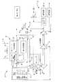
図1において、本発明の例示的な空気調和パック10が概略的に図示されている。パック10により、分配システム12に供給される調和空気が生成され、分配システム12により、空気が航空機のキャビンに供給される。過給器14により、パック入口に要求される圧力を有する圧縮空気がもたらされる。過給器14は、航空機がより効果的に作動するように航空機の主エンジンから空気を抽気する代替器として用いられる。 In FIG. 1, an exemplary
パック10は、熱交換器16を通る空気流をもたらすラム空気ダクト15を備え、空気がパック10内で調和される際に、熱交換器16により空気用のヒートシンクがもたらされる。ファン17により、ダクト15を通って空気が移動する。ACM18により、調和空気を生成するように流体ラインを通って流れる空気が圧縮され、膨張する。ACM18は、圧縮機44、第1のタービン46および第2のタービン48を備える三輪(three wheel)の機械である。ACMは、従来の型式であり、当業者に周知である。バルブシステム20は、制御部23に接続されるとともに、異なった流路を通して所望のように空気流を処理するように選択的にバルブを開閉する。湿度制御システム22により、パック10の所望の部分において、空気から湿気が除去される。 The
相対的に小さい主熱交換器24は、ラム空気ダクトに配置される。主熱交換器24は、地上状態または上昇(クライムアウト)状態において、公称の圧縮機出口温度に達するように、必要な熱除去をもたらす大きさに形成される。現在のシステムでは、主熱交換器は、高高度の巡航状態において熱除去をもたらす大きさに形成されており、その大きさは低高度状態に要求される場合と比べてかなり大きく、そのため、非効率である。また、本発明の補助熱交換器26は、ラム空気ダクト15に配置されている。補助熱交換器は、巡航状態における大きさに形成される。巡航状態では、パック供給空気の大部分がパック出口に迂回するため、高温側の流れは相対的に少ない。通常、補助熱交換器は、熱い日の地上補助電源装置状態における大きさに形成され、巡航状態において要求される大きさと比べかなり大きい。 A relatively small
本発明の主熱交換器24および補助熱交換器26は、従来のシステムと比べて小型化されているため、最悪の冷却状態に対応するように補助的な冷却が必要となる。このため、本発明では、第3の熱交換器28が用いられる。第3の熱交換器28は、最悪の状態時に所望の冷却をもたらすように主熱交換器24あるいは補助熱交換器26と選択的かつ流体的に接続される。キャビンに所望の冷却性能をもたらすように、主熱交換器24、補助熱交換器26および第3の熱交換器28の種々の組合せまたは形態を用いてもよい。 Since the
バルブシステム20は、第1のバルブ30を備え、第1のバルブ30により、主熱交換器24ないし第3の熱交換器28と湿度制御システム22との間に流体流が選択的に許容される。第2のバルブ32により、主熱交換器24とパック出口との間に流体流が選択的に許容される。第2のバルブ32は、通常、ACMバイパスバルブと呼ばれる。第3のバルブ34により、補助熱交換器26と湿気制御システム22との間に流体流が選択的に許容される。第4のバルブ36により、補助熱交換器26と第3の熱交換器28との間に流体流が選択的に許容される。第5のバルブ38により、第3の熱交換器28とパック出口との間に流体流が選択的に許容される。第6のバルブ40により、第3の熱交換器28と湿気制御システム22との間に流体流が選択的に許容される。第7のバルブ42により、
湿気制御システム22内の構成部品(例えば、集水器52とコンデンサ50との)間に流体流が選択的に許容される。The
Fluid flow is selectively allowed between components within the moisture control system 22 (eg, between the
分配システム12は、パック出口からの調和空気を受けるとともに、所望のように調和空気を航空機中に分配する。分配システム12は、キャビンからの再循環空気を受けるとともに、該再循環空気とパックからの調和空気を混合するミキサ54を備える。ミキサ54およびパック10からの空気は、当業者に周知のように、音響処理装置58,60を通って移動しシステムを通って流れる調和空気により生じる騒音を減少させる。 The
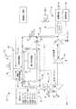
図2においては、暑い日/地上状態時のパック10が概略的に図示されている。図を簡略化するため、制御部23とバルブとの間の接続部分は省略している。過給器からの圧縮空気は、主熱交換器24に流入する。第2のバルブ32は、パック出口における所望の温度の空気をもたらすように開閉される。第1のバルブ30は、主熱交換器24からの空気が圧縮機44に流入するように閉鎖される。圧縮機44からの圧縮空気は、補助熱交換器26に流入する。補助熱交換器26からの空気が第3の熱交換器28に方向づけられるように、第3のバルブ34が閉鎖され、第4のバルブ36が開放される。第3の熱交換器28からの空気がコンデンサ50に流入するように、第5のバルブ38が閉鎖され、第6のバルブ40が開放される。空気は、コンデンサ50から集水器52に流入する。集水器52からの除湿された空気は、第7のバルブ42を通り調節され、タービン46を通って流れるか、あるいはコンデンサ50に戻るように流れる。コンデンサ50から、空気は第2のタービン48に向かって流れ、そこから空気はパック出口を通って流出する。 In FIG. 2, the
図3を参照すると、高高度/巡航状態が概略的に図示されている。過給器からの圧縮空気は、主熱交換器24に流入する。主熱交換器24からの所望の量の空気は、開放または少なくとも部分的に開放された第2のバルブ32を通ってパック出口に向かって流れる。主熱交換器24からの空気は、開放された第1のバルブ30を通って第3の熱交換器28に流入する。第5のバルブ38により、第3の熱交換器28からパック出口への流体流量が調節される。 Referring to FIG. 3, the high altitude / cruising condition is schematically illustrated. The compressed air from the supercharger flows into the
また、主熱交換器24からの圧縮空気の一部は、圧縮機44に流入する。圧縮機44からの空気は、補助熱交換器26に流入する。補助熱交換器26から湿気制御システム22に流体が流れるように、第4のバルブ36が閉鎖され、第3のバルブ34が開放される。湿気制御システム22から、第1のタービン46、次いで第2のタービン48に流体が流入する。第2のタービン48からの調和空気は、パック出口から流出する。
本発明の好ましい実施例が開示されたが、当業者であれば、特定の変更形態が本発明の範囲内にあることを理解されるであろう。そのため、本発明の範囲および内容を決定するために、添付の特許請求の範囲を検討されたい。A part of the compressed air from the
While preferred embodiments of the invention have been disclosed, those skilled in the art will appreciate that certain variations are within the scope of the invention. For that reason, the following claims should be studied to determine the scope and content of this invention.
Claims (12)
Translated fromJapanese前記主熱交換器および前記補助熱交換器と流体的に接続した第3の熱交換器と、
制御部からの指示に応じて、前記主熱交換器および前記補助熱交換器の少なくとも一方と前記第3の熱交換器を選択的かつ流体的に接続するバルブシステムと、
を備え、
前記バルブシステムが、第1の冷却性能をもたらすように前記第3の熱交換器および前記主熱交換器を流体的に接続するとともに、前記第1の冷却性能と異なった第2の冷却性能をもたらすように前記第3の熱交換器および前記補助熱交換器を流体的に接続することを特徴とする航空機用空気調和パック。A main heat exchanger and an auxiliary heat exchanger;
A third heat exchanger fluidly connected to the main heat exchanger and the auxiliary heat exchanger;
A valve system that selectively and fluidly connects at least one of the main heat exchanger and the auxiliary heat exchanger and the third heat exchanger according to an instruction from a control unit;
With
The valve system fluidly connects the third heat exchanger and the main heat exchanger so as to provide a first cooling performance, and has a second cooling performance different from the first cooling performance. An aircraft air conditioning pack characterized in that the third heat exchanger and the auxiliary heat exchanger are fluidly connected to provide.
Applications Claiming Priority (3)
| Application Number | Priority Date | Filing Date | Title |
|---|---|---|---|
| US50467103P | 2003-09-22 | 2003-09-22 | |
| US10/716,313US6942183B2 (en) | 2003-09-22 | 2003-11-18 | Air cycle air conditioning with adaptive ram heat exchanger |
| PCT/US2004/030942WO2005030583A1 (en) | 2003-09-22 | 2004-09-22 | Air cycle air conditioning with adaptive ram heat exchanger |
Publications (2)
| Publication Number | Publication Date |
|---|---|
| JP2007505787A JP2007505787A (en) | 2007-03-15 |
| JP4489776B2true JP4489776B2 (en) | 2010-06-23 |
Family
ID=34316685
Family Applications (1)
| Application Number | Title | Priority Date | Filing Date |
|---|---|---|---|
| JP2006527139AExpired - Fee RelatedJP4489776B2 (en) | 2003-09-22 | 2004-09-22 | Air cycle air conditioning with adaptive ram heat exchanger |
Country Status (7)
| Country | Link |
|---|---|
| US (1) | US6942183B2 (en) |
| EP (1) | EP1667905B1 (en) |
| JP (1) | JP4489776B2 (en) |
| AT (1) | ATE378254T1 (en) |
| DE (1) | DE602004010160T2 (en) |
| ES (1) | ES2293345T3 (en) |
| WO (1) | WO2005030583A1 (en) |
Families Citing this family (44)
| Publication number | Priority date | Publication date | Assignee | Title |
|---|---|---|---|---|
| DE102004010366B4 (en)* | 2004-03-03 | 2008-03-27 | Liebherr-Aerospace Lindenberg Gmbh | System for compressed air preparation |
| US7322202B2 (en)* | 2004-09-22 | 2008-01-29 | Hamilton Sundstrand Corporation | Electric motor driven supercharger with air cycle air conditioning system |
| DE102005037285A1 (en) | 2005-08-08 | 2007-02-15 | Liebherr-Aerospace Lindenberg Gmbh | Method for operating an aircraft air conditioning system |
| US7334422B2 (en)* | 2005-11-29 | 2008-02-26 | Hamilton Sundstrand Corporation | Cabin air conditioning system with liquid cooling for power electronics |
| DE102006050869A1 (en)* | 2006-10-27 | 2008-04-30 | Airbus Deutschland Gmbh | Sound proofing device for air pipe line of airplane, has air conduction means that is arranged within curved pipe section that is equipped with micro perforation at side surface for further weight neutral sound proofing |
| US7695355B2 (en)* | 2007-07-16 | 2010-04-13 | Hamilton Sundstrand Corporation | Integrated housing for fan and alternate flow check valve |
| US20100206543A1 (en)* | 2009-02-13 | 2010-08-19 | Tylisz Brian M | Two-stage heat exchanger with interstage bypass |
| US8590603B2 (en)* | 2009-12-08 | 2013-11-26 | Hamilton Sundstrand Corporation | Heat exchanger insulation gap |
| US8910465B2 (en) | 2009-12-31 | 2014-12-16 | Rolls-Royce North American Technologies, Inc. | Gas turbine engine and heat exchange system |
| WO2011124390A1 (en)* | 2010-04-09 | 2011-10-13 | Airbus Operations Gmbh | Mixer assembly for an aircraft air conditioning system |
| US9574570B2 (en) | 2010-11-03 | 2017-02-21 | Hamilton Sundstard Corporation | Shaft speed and vibration sensor apparatus |
| US8955794B2 (en)* | 2012-01-24 | 2015-02-17 | The Boeing Company | Bleed air systems for use with aircrafts and related methods |
| US8967528B2 (en)* | 2012-01-24 | 2015-03-03 | The Boeing Company | Bleed air systems for use with aircrafts and related methods |
| US9511869B2 (en) | 2012-12-21 | 2016-12-06 | Hamilton Sunstrand Corporation | Mixer and air pack for use in aircraft air supply system |
| US10144518B2 (en) | 2013-01-17 | 2018-12-04 | Hamilton Sundstrand Corporation | Dual action check valve with combined return and bypass passages |
| US9840967B2 (en) | 2013-03-04 | 2017-12-12 | Rolls-Royce North American Technologies, Inc. | Ram air thermal management system |
| US9157683B2 (en) | 2013-04-02 | 2015-10-13 | Hamilton Sundstrand Corporation | Heat exchanger for aircraft application |
| US10072502B2 (en) | 2013-04-24 | 2018-09-11 | Hamilton Sundstrand Corporation | Turbine nozzle and shroud for air cycle machine |
| US10006299B2 (en) | 2013-04-24 | 2018-06-26 | Hamilton Sundstrand Corporation | Turbine nozzle for air cycle machine |
| US10072512B2 (en) | 2013-04-24 | 2018-09-11 | Hamilton Sundstrand Corporation | Turbine nozzle and shroud |
| US10072519B2 (en) | 2013-04-24 | 2018-09-11 | Hamilton Sundstrand Corporation | Turbine nozzle for air cycle machine |
| US10087760B2 (en) | 2013-04-24 | 2018-10-02 | Hamilton Sundstrand Corporation | Turbine nozzle and shroud for air cycle machine |
| US9957051B2 (en)* | 2013-09-03 | 2018-05-01 | Hamilton Sundstrand Corporation | Method of operating a multi-pack environmental control system |
| US9656755B2 (en) | 2013-12-13 | 2017-05-23 | The Boeing Company | Air cycle machine pack system and method for improving low inlet pressure cooling performance |
| US9580180B2 (en) | 2014-03-07 | 2017-02-28 | Honeywell International Inc. | Low-pressure bleed air aircraft environmental control system |
| US9810158B2 (en) | 2014-04-01 | 2017-11-07 | The Boeing Company | Bleed air systems for use with aircraft and related methods |
| US10054051B2 (en) | 2014-04-01 | 2018-08-21 | The Boeing Company | Bleed air systems for use with aircraft and related methods |
| US9862494B2 (en) | 2014-09-25 | 2018-01-09 | Hamilton Sundstrand Corporation | Flight deck tap off for mixer |
| US9598175B2 (en)* | 2015-04-24 | 2017-03-21 | Hamilton Sundstrand Corporation | Modular environmental air conditioning system |
| US10100744B2 (en) | 2015-06-19 | 2018-10-16 | The Boeing Company | Aircraft bleed air and engine starter systems and related methods |
| US20170217592A1 (en)* | 2016-02-01 | 2017-08-03 | General Electric Company | Aircraft Thermal Management System |
| US10533784B2 (en) | 2016-03-16 | 2020-01-14 | Hamilton Sundstrand Corporation | Pack-and-A-half architecture for environmental control systems |
| US10870490B2 (en)* | 2016-05-26 | 2020-12-22 | Hamilton Sunstrand Corporation | Energy flow |
| US10358221B2 (en)* | 2016-08-23 | 2019-07-23 | Ge Aviation Systems Llc | Hybrid method and aircraft for pre-cooling an environmental control system using a power generator four wheel turbo-machine |
| US10745137B2 (en) | 2017-01-27 | 2020-08-18 | Hamilton Sunstrand Corporation | Advanced environmental control system in an integrated split pack arrangement with one bleed/outflow heat exchanger |
| US10822095B2 (en) | 2017-01-27 | 2020-11-03 | Hamilton Sundstrand Corporation | Advanced environmental control system in an integrated pack arrangement with one bleed/outflow heat exchanger |
| US11358725B2 (en) | 2017-06-28 | 2022-06-14 | Hamilton Sundstrand Corporation | Three wheel and simple cycle aircraft environmental control system |
| US10850854B2 (en) | 2017-06-28 | 2020-12-01 | Hamilton Sunstrand Corporation | Three wheel and simple cycle aircraft environmental control system |
| US11192655B2 (en)* | 2017-11-03 | 2021-12-07 | Hamilton Sundstrand Corporation | Regenerative system ECOECS |
| EP3521169B1 (en)* | 2018-02-05 | 2021-11-24 | Hamilton Sundstrand Corporation | Three wheel and simple cycle aircraft environmental control system |
| US10954865B2 (en) | 2018-06-19 | 2021-03-23 | The Boeing Company | Pressurized air systems for aircraft and related methods |
| US11465757B2 (en) | 2018-12-06 | 2022-10-11 | The Boeing Company | Systems and methods to produce aircraft cabin supply air |
| US10962294B2 (en)* | 2018-12-07 | 2021-03-30 | Hamilton Sundstrand Corporation | Dual pass heat exchanger with drain system |
| US11486315B2 (en) | 2020-11-06 | 2022-11-01 | Ge Aviation Systems Llc | Combustion engine including turbomachine |
Family Cites Families (8)
| Publication number | Priority date | Publication date | Assignee | Title |
|---|---|---|---|---|
| US1580504A (en)* | 1925-01-03 | 1926-04-13 | Lava Mario | Variable radiator |
| US3776305A (en)* | 1972-02-22 | 1973-12-04 | United Aircraft Prod | Heat transfer system |
| JP2875309B2 (en)* | 1989-12-01 | 1999-03-31 | 株式会社日立製作所 | Air conditioner, heat exchanger used in the device, and control method for the device |
| US5423498A (en)* | 1993-04-27 | 1995-06-13 | E-Systems, Inc. | Modular liquid skin heat exchanger |
| US5906111A (en)* | 1997-07-11 | 1999-05-25 | Alliedsignal Inc. | Liquid cooled high pressure separation for air cycle cooling system |
| US6128909A (en)* | 1998-06-04 | 2000-10-10 | Alliedsignal Inc. | Air cycle environmental control systems with two stage compression and expansion and separate ambient air fan |
| DE19936641C2 (en)* | 1999-08-04 | 2001-06-13 | Eads Airbus Gmbh | Air conditioning device for passenger aircraft |
| FR2800706B1 (en)* | 1999-11-10 | 2002-01-18 | Dassault Aviat | METHOD AND DEVICE FOR SUPPLYING A FRESH AIR INTAKE FROM THE CABIN OF AN AIRCRAFT POWERED BY AT LEAST ONE JET ENGINE |
- 2003
- 2003-11-18USUS10/716,313patent/US6942183B2/ennot_activeExpired - Fee Related
- 2004
- 2004-09-22ESES04784698Tpatent/ES2293345T3/ennot_activeExpired - Lifetime
- 2004-09-22ATAT04784698Tpatent/ATE378254T1/ennot_activeIP Right Cessation
- 2004-09-22DEDE602004010160Tpatent/DE602004010160T2/ennot_activeExpired - Lifetime
- 2004-09-22WOPCT/US2004/030942patent/WO2005030583A1/enactiveIP Right Grant
- 2004-09-22JPJP2006527139Apatent/JP4489776B2/ennot_activeExpired - Fee Related
- 2004-09-22EPEP04784698Apatent/EP1667905B1/ennot_activeExpired - Lifetime
Also Published As
| Publication number | Publication date |
|---|---|
| WO2005030583A1 (en) | 2005-04-07 |
| US20050061911A1 (en) | 2005-03-24 |
| EP1667905A1 (en) | 2006-06-14 |
| DE602004010160D1 (en) | 2007-12-27 |
| ES2293345T3 (en) | 2008-03-16 |
| EP1667905B1 (en) | 2007-11-14 |
| JP2007505787A (en) | 2007-03-15 |
| ATE378254T1 (en) | 2007-11-15 |
| DE602004010160T2 (en) | 2008-10-30 |
| US6942183B2 (en) | 2005-09-13 |
Similar Documents
| Publication | Publication Date | Title |
|---|---|---|
| JP4489776B2 (en) | Air cycle air conditioning with adaptive ram heat exchanger | |
| JP6165413B2 (en) | Environmental control system supply precooler bypass | |
| US10076944B2 (en) | Vehicle cabin air conditioning and battery cooling system | |
| JP5156706B2 (en) | Environmental harmony system and environmental harmony method | |
| EP3385169B1 (en) | Hybrid third air condition pack | |
| EP3640562B1 (en) | Heat recovery multi-split air conditioning system with a mode switcher and control method | |
| CN102971215B (en) | Compressor/turbine arrangement, air conditioning unit and method for operating a compressor/turbine arrangement | |
| CN209813715U (en) | Vehicle thermal management systems and vehicles | |
| US12220969B2 (en) | Cooling system with a heat pump function based on an extendable base system and motor vehicle with a cooling system of this type | |
| JP2007045398A (en) | Aircraft system operation method | |
| CA2416398A1 (en) | A system for dehumidification in air conditioners | |
| EP4516538A1 (en) | Integrated module for vehicle thermal management system, vehicle thermal management system, and vehicle | |
| JP2014516858A (en) | Air conditioning system for aircraft passenger compartment | |
| WO2013067886A1 (en) | Refrigeration system for aircraft | |
| CN207471687U (en) | Air-conditioning system and the air conditioner with the air-conditioning system | |
| EP3838762A1 (en) | Air cycle machines, air cycle machine systems, and methods of controlling air flow in air cycle machines | |
| US5309724A (en) | Switchable heat exchanger configuration for air cycle cooling apparatus | |
| WO2020095477A1 (en) | Aircraft air conditioning device | |
| CN118056755A (en) | Environment control device for an aircraft and method for operating an environment control device | |
| JP4315768B2 (en) | Air-conditioning ventilation system for high-speed railway vehicles | |
| JP4206615B2 (en) | Air conditioner for aircraft | |
| JP2013244751A (en) | Air-conditioning system | |
| JP2000203496A (en) | Aircraft environmental control device | |
| US11046441B2 (en) | Adaptive plate-fin heat exchanger | |
| JP2004256051A (en) | Liquid-cooling device for aircraft |
Legal Events
| Date | Code | Title | Description |
|---|---|---|---|
| A621 | Written request for application examination | Free format text:JAPANESE INTERMEDIATE CODE: A621 Effective date:20070913 | |
| TRDD | Decision of grant or rejection written | ||
| A01 | Written decision to grant a patent or to grant a registration (utility model) | Free format text:JAPANESE INTERMEDIATE CODE: A01 Effective date:20100309 | |
| A01 | Written decision to grant a patent or to grant a registration (utility model) | Free format text:JAPANESE INTERMEDIATE CODE: A01 | |
| A61 | First payment of annual fees (during grant procedure) | Free format text:JAPANESE INTERMEDIATE CODE: A61 Effective date:20100331 | |
| FPAY | Renewal fee payment (event date is renewal date of database) | Free format text:PAYMENT UNTIL: 20130409 Year of fee payment:3 | |
| R150 | Certificate of patent or registration of utility model | Free format text:JAPANESE INTERMEDIATE CODE: R150 | |
| R250 | Receipt of annual fees | Free format text:JAPANESE INTERMEDIATE CODE: R250 | |
| LAPS | Cancellation because of no payment of annual fees |