JP4489219B2 - Balloon catheter protection - Google Patents
Balloon catheter protectionDownload PDFInfo
- Publication number
- JP4489219B2 JP4489219B2JP26292899AJP26292899AJP4489219B2JP 4489219 B2JP4489219 B2JP 4489219B2JP 26292899 AJP26292899 AJP 26292899AJP 26292899 AJP26292899 AJP 26292899AJP 4489219 B2JP4489219 B2JP 4489219B2
- Authority
- JP
- Japan
- Prior art keywords
- balloon catheter
- balloon
- tip
- protective
- connection adapter
- Prior art date
- Legal status (The legal status is an assumption and is not a legal conclusion. Google has not performed a legal analysis and makes no representation as to the accuracy of the status listed.)
- Expired - Fee Related
Links
- 230000001681protective effectEffects0.000claimsdescription47
- 238000011010flushing procedureMethods0.000claimsdescription34
- 239000012530fluidSubstances0.000claimsdescription28
- 230000001012protectorEffects0.000claimsdescription13
- 239000011162core materialSubstances0.000claimsdescription10
- 239000007924injectionSubstances0.000claimsdescription10
- 238000002347injectionMethods0.000claimsdescription10
- 230000008878couplingEffects0.000claimsdescription4
- 238000010168coupling processMethods0.000claimsdescription4
- 238000005859coupling reactionMethods0.000claimsdescription4
- 230000003902lesionEffects0.000description8
- 210000004204blood vesselAnatomy0.000description7
- -1polyethylenePolymers0.000description7
- 238000000034methodMethods0.000description6
- 230000002093peripheral effectEffects0.000description6
- 239000002504physiological saline solutionSubstances0.000description5
- 239000004743PolypropyleneSubstances0.000description4
- 229920001155polypropylenePolymers0.000description4
- 239000004698PolyethyleneSubstances0.000description3
- 238000002399angioplastyMethods0.000description3
- 229920000573polyethylenePolymers0.000description3
- 229920005989resinPolymers0.000description3
- 239000011347resinSubstances0.000description3
- 239000004812Fluorinated ethylene propyleneSubstances0.000description2
- 208000031481Pathologic ConstrictionDiseases0.000description2
- HQQADJVZYDDRJT-UHFFFAOYSA-Nethene;prop-1-eneChemical groupC=C.CC=CHQQADJVZYDDRJT-UHFFFAOYSA-N0.000description2
- 229920009441perflouroethylene propylenePolymers0.000description2
- 229920000098polyolefinPolymers0.000description2
- 230000036262stenosisEffects0.000description2
- 208000037804stenosisDiseases0.000description2
- KKJUPNGICOCCDW-UHFFFAOYSA-N7-N,N-Dimethylamino-1,2,3,4,5-pentathiocyclooctaneChemical compoundCN(C)C1CSSSSSC1KKJUPNGICOCCDW-UHFFFAOYSA-N0.000description1
- 208000018672DilatationDiseases0.000description1
- 229910000831SteelInorganic materials0.000description1
- 208000007536ThrombosisDiseases0.000description1
- 239000000853adhesiveSubstances0.000description1
- 230000004323axial lengthEffects0.000description1
- 238000005452bendingMethods0.000description1
- 230000015572biosynthetic processEffects0.000description1
- 230000008602contractionEffects0.000description1
- 238000003745diagnosisMethods0.000description1
- 230000000694effectsEffects0.000description1
- 229920005672polyolefin resinPolymers0.000description1
- 239000010959steelSubstances0.000description1
Images


Landscapes
- Media Introduction/Drainage Providing Device (AREA)
Description
Translated fromJapanese【0001】
【発明の属する技術分野】
本発明は、血管や脈管その他体内の管状組織の治療もしくは診断に用いる医療用バルーンカテーテルの先端部を保護する保護具に関するものである。
【0002】
【従来の技術】
従来から、バルーンカテーテルは、血管内腔の狭窄部や閉塞部などを拡張治療する経皮的血管形成術などにおいて広く使われている。一般的なバルーンカテーテルは、カテーテルシャフトの遠位端に内圧調整により膨張または収縮するバルーンを接合してなるものであり、カテーテルシャフトの内部には、ガイドワイヤが挿通される内腔(ガイドワイヤルーメン)や、前記バルーンに供給する圧力流体を通す内腔(インフレーションルーメン)が軸方向に沿って形成されている。このようなバルーンカテーテルを用いた血管形成術は、以下の手順で行われる。先ず、ガイドワイヤルーメンに挿通したガイドワイヤを狭窄部などの病変部位に通過させ、このガイドワイヤに沿ってバルーンを体内に挿入して病変部位に一致させ、適度に希釈した造影剤などの圧力流体をインフレーションルーメンに供給してバルーンを拡張させて、当該病変部位を拡張治療する。当該病変部位が拡張治療された後は、バルーンを減圧収縮して折畳んだ後に体外に抜去し、血管形成術を終了する。
【0003】
このようなバルーンカテーテルの先端部は予め保護具が被せられ保護されているのが一般的であり、バルーンカテーテルは手技の際に保護具を抜き取って使用される。この保護具を用いる理由の一つは、使用前にバルーン部分の損傷を防ぐことにある。バルーン部分に折れなどの損傷が生じたとき、バルーンが血管内腔を通る際に血管内壁を傷つけ易く、またガイドワイヤルーメンも折れてしまいバルーンを押し込む際の抵抗力が増すため、バルーンを病変部位に正確に誘導することが困難になる。また、損傷を受けたバルーンを拡張させる際このバルーンに破裂もしくは圧力流体の漏れが発生する危険性が高く、重大な医療事故に至る場合もある。
【0004】
保護具を用いる理由の二つ目は、手技を行う直前までバルーンの外径をできる限り小さくするためである。これは、血管内腔に対してバルーン外径が小さい程に、血管壁とバルーンとの接触面積が小さくなり、且つバルーンを押し込む際の抵抗力が小さくなるので、バルーンを病変部位へ誘導し易いからであるが、更には、難易度や屈曲度の高い病変部位、ステント内部などの表面抵抗が高い部位などにおいては、バルーン外径を小さく保つことによりバルーンの病変部位の通過性が向上するからでもある。
【0005】
また、手技を行う前は、保護具をバルーンカテーテルから抜きとった後、血栓形成防止のためにガイドワイヤルーメンに生理食塩水などを供給してフラッシングしたり、生理食塩水で満たしたりし、更には、バルーンカテーテルの外表面を生理食塩水に浸漬する場合がある。特にフラッシングする際、ガイドワイヤルーメンがカテーテルの基端から先端まで連通しているタイプ(一般に「オーバー・ザ・ワイヤ型」と呼ばれる。)のバルーンカテーテルでは、フラッシング用の生理食塩水などをカテーテル基端に備わるハブのポートを通じてガイドワイヤルーメンに供給すれば良く、フラッシングは容易である。しかしながら、図5に例示するようなモノレール型バルーンカテーテル40ではオーバー・ザ・ワイヤ型の場合と事情が異なる。図示したモノレール型バルーンカテーテル40は、遠位側シャフト41と近位側シャフト42とを接合してなり、前記遠位側シャフト41の遠位端にバルーン43を接合し、前記近位側シャフト42の基端にバルーン43へ圧力流体を供給するためのポート44aを備えたハブ44を有し、且つ遠位側シャフト41の内部に長軸方向に沿ったガイドワイヤルーメン45を形成して構成されるものである。ガイドワイヤルーメン45の後端開口部45aはシャフトの途中部に設けられているため、カテーテル基端側に備わるハブ44からフラッシング用流体をガイドワイヤルーメン45に供給できない。そこで、従来は、ガイドワイヤルーメンの先端開口部45bに、当該先端開口部45bの内径と略同じ若しくはやや小さい外径を有する注射針を差し込み、更にその注射針を保持する注射針保持部材を注射筒に挿着して、当該ガイドワイヤルーメン45にフラッシング用流体を供給し、フラッシングを実行していた。
【0006】
【発明が解決しようとする課題】
しかしながら、バルーンカテーテル先端部の外径は、約0.5mm〜3.0mm程度であり極めて小さいため、上記先端開口部45bからガイドワイヤルーメン45に注射針を差し込みフラッシングする際、その作業が煩雑となると同時に、その先端部が折り曲げられたり、ラッパ状に変形されたり、損傷する等のトラブルが発生し易い。このような場合は、手技の際にバルーンを当該病変部位まで導くことは極めて困難になる。
【0007】
以上の問題に鑑み本発明が解決しようとするところは、煩雑な作業を伴わず、且つバルーンカテーテル先端部の損傷および変形を生じさせずに、バルーンカテーテルのガイドワイヤルーメンをフラッシングすることが可能なバルーンカテーテル用保護具を提供する点にある。
【0008】
【課題を解決するための手段】
前記課題を解決すべく、本発明者らはバルーンカテーテル先端部を被覆する保護具に着目し鋭意研究した結果、本発明に到達するに至った。すなわち、本発明に係るバルーンカテーテル用保護具は、医療用バルーンカテーテルのバルーンを含む先端部を被覆保護する保護管部と、フラッシング用流体供給器具と着脱自在に連結する連結アダプターとを備え、前記保護管部の内径が折畳み状態のバルーンの外径に合わせて選択され、前記連結アダプターにフラッシング用流体供給器である注射器の筒先が着脱自在に挿着され、かつ前記筒先が密着して嵌合する連結ポートを備え、前記折畳み状態のバルーンを含むカテーテル先端部に取り外し可能に取り付けられることを特徴とするものである。これにより、前記保護管部の内部にバルーンカテーテル先端部を挿入し被覆保護した状態で、前記連結アダプターにフラッシング用流体供給器を連結し、このフラッシング用流体供給器を通じてバルーンカテーテルのガイドワイヤルーメンにフラッシング用流体を供給してフラッシングすることができる。このフラッシング作業の間、バルーンカテーテル先端部は前記保護管部の内部において被覆保護された状態にあるから、当該先端部を折り曲げたり、ラッパ状に変形させたり、損傷させたりすることなどが防止される。
【0009】
また、前記フラッシング用流体供給器として注射器を用いるとき、比較的大型の注射器を用いる場合は、上記連結アダプターに、フラッシング用流体供給器と連結するルーアーロック結合部を備えることが好ましい。また、上記連結アダプターは、注射針保持部材が着脱自在に挿着される連結ポートを備えたものでも良い。
また、本発明に係るバルーンカテーテル用保護具は、陰圧を加えて折畳み状態にしたバルーンを有するバルーンカテーテル先端部を内挿し被覆保護してなるものでも良い。また、本発明に係るバルーンカテーテル用保護具によりバルーン先端部が被覆保護されたバルーンカテーテルは、前記フラッシング作業の間、バルーンカテーテル先端部は前記保護管部の内部において被覆保護された状態にあるから、当該先端部を折り曲げたり、ラッパ状に変形させたり、損傷させたりすることなどが防止される。また、前記バルーンカテーテルはガイドワイヤルーメンを構成するインナーシャフトを保護する保護用芯材が挿入されていることが好ましい。
【0010】
【発明の実施の形態】
以下、図面を参照しつつ本発明に係る種々の実施形態について説明する。
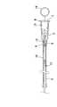
図1は、本発明に係るバルーンカテーテル用保護具の一実施例を示す概略図である。同図(a)は、本実施例のバルーンカテーテル用保護具を示す断面図であり、同図(b)は、同バルーンカテーテル用保護具の右側面図である。
本実施例のバルーンカテーテル用保護具1は、バルーンカテーテル先端部を内挿し被覆保護する筒状の保護管部2と、この保護管部2の基端部4に同軸状に嵌着され且つ注射筒などのフラッシング用流体供給器と連結する連結アダプター3とを備えて構成されている。尚、前記保護管部2と連結アダプター3とは接着剤を用いて接着されてもよいし、熱溶着されてもよい。また、本実施例では、保護管部2と連結アダプター3とを嵌合しているが本発明ではこれに限らず、保護管部2と連結アダプター3とを一体成形しても構わない。
【0011】
前記保護管部2は、ポリオレフィン、フッ素化ポリオレフィンなどの樹脂からなり、好ましくはポリエチレン、ポリプロピレン、フッ素化ポリエチレン、フッ素化ポリプロピレンおよびフッ素化エチレンプロピレン共重合体、特に好ましくはフッ素化エチレンプロピレン共重合体からなり、少なくともバルーンを被覆保護し得る長さを有し、一般的には5.0mm〜100.0mm、好ましくは7.0mm〜80.0mmの軸方向長さを有するものである。また、前記保護管部2の先端部内腔5aは、バルーンを挿入し易いように先端に行くに従い漸次拡径するテーパー形状に成形されており、保護管部2の内径は、適用する折畳み状態のバルーンの外径に合わせて選択されるが、一般的には0.1mm〜4.0mmであり、好ましくは0.3mm〜2.0mm、更に好ましくは0.5mm〜1.2mmである。尚、この保護管部2からのバルーンカテーテルの抜き取りを容易にすべく、保護管部2の内腔5bを基端部4から先端部に行くに従い漸次緩やかに拡径するテーパー形状にしても構わない。
【0012】
また、前記連結アダプター3は、主としてポリエチレンやポリプロピレンのようなポリオレフィン系樹脂、好ましくはポリプロピレン樹脂からなり、保護管部2の基端部4と嵌合する円筒状の嵌合部6と、注射器などのフラッシング用流体供給器と連結し得る連結ポート7とを備え、その後端外周部には環状のフランジ8が形成されている。また、前記連結アダプター3の内部には、前記連結ポート7から供給されるフラッシング用流体が流通し且つ前記保護管部2の内腔5bに連通する流通路9が形成されている。更には、図1(b)に示すように、前記フランジ8には、その中心軸に対して180度で対向する位置にルーアーロックタブ8a,8bが形成されている。
【0013】
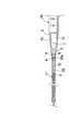
以上の構造を有するバルーンカテーテル用保護具1は、使用前には、図2に示すように、陰圧を加えて折畳み状態にしたバルーン10を有するバルーンカテーテル先端部11を内挿し被覆保護している。また、ガイドワイヤルーメンを構成するインナーシャフトを保護すべく、当該インナーシャフトに鋼製の保護用芯材12が挿入されている。また、保護用芯材12は樹脂製の芯材保持部13の前端面に固着され、この芯材保持部13は連結ポート7に着脱自在にはめ込まれており、この芯材保持部13の後端面には、前記インナーシャフトから保護用芯材12を容易に抜き取ることが可能なようにピン14が固着されている。
【0014】
本実施例の保護具を実際に使用する際には、前記インナーシャフトから保護用芯材12を抜き取り、連結アダプター3にフラッシング用流体供給器を連結する。ここでいう連結とは、バルーンカテーテルのガイドワイヤールーメンを生理食塩水などでフラッシングする際に、本実施例の保護具とフラッシング用流体供給器とが外れない程度に固定された状態をいう。図3に、比較的小容量の注射器20の筒先21を連結アダプター3に連結した状態を示す。フラッシング用流体供給器である注射器20の筒先21は、テーパー形状の外周面を有し、連結ポート7のテーパー形状の内周面7aと合致し密着されることにより、連結ポート7に着脱自在に挿着されている。この状態で、注射器20内のフラッシング用流体を連結ポート7に注入し流通路9を通して、バルーンカテーテルのガイドワイアルーメン22の先端開口部22aへ流入させ、ガイドワイアルーメン22をフラッシングする。そして、フラッシングを終えたバルーンカテーテルからバルーンカテーテル用保護具1を取り外し、PTCAなどの手技を実行する。
【0015】
尚、前記実施例は、注射筒の筒先21と連結ポート7とを嵌合するものであったが、他の実施例として、注射針を保持する注射針保持部材(図示せず)を嵌合せしめる連結ポートを採用してもよい。この場合、連結ポートの内周面は、注射針保持部材の外周面に合致し密着し得るテーパー形状を有するように形成される。
【0016】
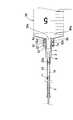
また、図4に、いわゆるルーアーロック結合により、比較的大容量の注射器30の筒先31を連結アダプター3に連結した状態を示す。注射器30の筒先31は、外側筒部32と内側筒部33とを同軸状に配置した構造を有しており、前記外側筒部32の内周面には二重に螺旋状凸部32a,32bが形成され、前記内側筒部33の中空部33aは、注射筒30の内部空間30aに連通している。そして、これらの螺旋状凸部32a,32bの間の溝に沿って連結アダプター3のルーアーロックタブ8a,8bを回動して嵌合し、内側筒部33の外周面を、テーパー形状を有する前記連結ポート7の内周面7aと合致し密着させる。これにより連結アダプター3に注射器30の筒先31が連結される。この状態で、注射器30の内部空間30aにおけるフラッシング用流体を連結ポート7に注入し流通路9を通して、バルーンカテーテルのガイドワイアルーメン22の先端開口部22aへ流入させて、ガイドワイアルーメン22をフラッシングすることができる。
【0017】
【発明の効果】
以上の如く、本発明に係るバルーンカテーテル用保護具は、医療用バルーンカテーテルのバルーンを含む先端部を被覆保護する保護管部と、フラッシング用流体供給器と着脱自在に連結する連結アダプターとを備えるものなので、前記保護管部の内部にバルーンカテーテル先端部を挿入し被覆保護した状態で、前記連結アダプターにフラッシング用流体供給器を連結し、バルーンカテーテルのガイドワイヤルーメンにフラッシング用流体を流入してフラッシングを実行できる。よって、煩雑な作業を伴わず、且つバルーンカテーテル先端部の損傷および変形を生じさせずに、バルーンカテーテルのガイドワイヤルーメンをフラッシングすることが可能となる。
【図面の簡単な説明】
【図1】(a)は、本発明に係るバルーンカテーテル用保護具の一実施例を示す概略断面図であり、(b)は、同バルーンカテーテル用保護具の右側面図である。
【図2】バルーンカテーテル先端部を被覆保護したバルーンカテーテル用保護具の一実施例を示す概略断面図である。
【図3】注射器を連結アダプターに連結した状態を示す概略断面図である。
【図4】注射器を連結アダプターにルーアーロック結合した状態を示す概略断面図である。
【図5】一般的なモノレール型バルーンカテーテルを示す概略図である。
【符号の説明】
1 バルーンカテーテル用保護具
2 保護管部
3 連結アダプター
4 保護管部の基端部
5a 保護管部の先端部内腔
5b 保護管部の内腔
6 嵌合部
7 連結ポート
8 フランジ
8a,8b ルーアーロックタブ
9 流通路
10 バルーン
11 バルーンカテーテル先端部
12 保護用芯材
13 芯材保持部
14 ピン
20 注射器
21 注射器の筒先
22 ガイドワイヤルーメン
22a ガイドワイヤルーメンの先端開口部
30 注射器
30a 注射器の内部空間
31 注射器の筒先
32 外側筒部
32a,32b 螺旋状凸部
33 内側筒部
40 モノレール型バルーンカテーテル
41 遠位側シャフト
42 近位側シャフト
43 バルーン
44 ハブ
44a 圧力流体供給用ポート
45 ガイドワイヤルーメン
45a ガイドワイヤルーメンの後端開口部
45b ガイドワイヤルーメンの先端開口部[0001]
BACKGROUND OF THE INVENTION
The present invention relates to a protective device for protecting a distal end portion of a medical balloon catheter used for treatment or diagnosis of blood vessels, blood vessels, and other tubular tissues in the body.
[0002]
[Prior art]
Conventionally, balloon catheters have been widely used in percutaneous angioplasty for expanding and treating stenosis and occlusions of blood vessel lumens. A general balloon catheter is formed by joining a balloon that is inflated or deflated by adjusting the internal pressure to the distal end of a catheter shaft. Inside the catheter shaft is a lumen through which a guide wire is inserted (guide wire lumen). ) And a lumen (inflation lumen) through which the pressure fluid supplied to the balloon passes is formed along the axial direction. Angioplasty using such a balloon catheter is performed according to the following procedure. First, a guide fluid inserted through the guide wire lumen is passed through a lesion site such as a stenosis, and a balloon is inserted into the body along the guide wire to match the lesion site. Is supplied to the inflation lumen to expand the balloon, and the lesion site is expanded. After the lesion site has been subjected to dilatation treatment, the balloon is contracted by contraction under reduced pressure and then removed from the body to complete the angioplasty.
[0003]
In general, the tip of such a balloon catheter is protected with a protective device in advance, and the balloon catheter is used by removing the protective device during the procedure. One reason for using this protective device is to prevent damage to the balloon portion before use. When damage such as bending occurs in the balloon part, it is easy to damage the inner wall of the blood vessel when it passes through the lumen of the blood vessel, and the guide wire lumen also breaks, and the resistance force when pushing the balloon is increased. It becomes difficult to guide accurately. Also, when a damaged balloon is expanded, there is a high risk that the balloon will burst or leak pressure fluid, which may lead to a serious medical accident.
[0004]
The second reason for using the protective equipment is to make the outer diameter of the balloon as small as possible until immediately before performing the procedure. This is because the smaller the outer diameter of the balloon relative to the lumen of the blood vessel, the smaller the contact area between the blood vessel wall and the balloon, and the smaller the resistance when pushing the balloon, the easier it is to guide the balloon to the lesion site. In addition, in a lesion site with a high degree of difficulty and flexibility, or in a site with a high surface resistance such as the inside of a stent, the passage of the balloon lesion site is improved by keeping the balloon outer diameter small. But there is.
[0005]
Before performing the procedure, after removing the protective device from the balloon catheter, flushing by supplying physiological saline or the like to the guide wire lumen to prevent thrombus formation, or filling with physiological saline, May soak the outer surface of the balloon catheter in physiological saline. In particular, when flushing, a balloon catheter of a type in which a guide wire lumen communicates from the proximal end to the distal end of the catheter (generally referred to as “over-the-wire type”), a physiological saline for flushing is used as the catheter base. What is necessary is just to supply to a guide wire lumen through the port of the hub provided at the end, and flushing is easy. However, in the monorail
[0006]
[Problems to be solved by the invention]
However, the outer diameter of the balloon catheter tip is about 0.5 mm to 3.0 mm, which is extremely small. Therefore, when the injection needle is inserted into the
[0007]
In view of the above problems, the present invention intends to solve the problem that the guide wire lumen of the balloon catheter can be flushed without complicated work and without causing damage and deformation of the balloon catheter tip. It is in providing a protective device for a balloon catheter.
[0008]
[Means for Solving the Problems]
In order to solve the above-mentioned problems, the present inventors have intensively studied paying attention to a protective device covering the tip of the balloon catheter, and as a result, have reached the present invention. That is, a balloon catheter protector according to the present invention includes a protective tube portion that covers and protects a distal end portion including a balloon of a medical balloon catheter, and a connection adapter that is detachably connected to a flushing fluid supply instrument, The inner diameter of the protective tube is selected according to the outer diameter of the folded balloon, and the syringe barrel that is a flushing fluid supply device is detachably inserted into the connecting adapter, and the barrel tip is closely fitted. a connecting portfor, and is characterized in Rukotoremovably attached to the catheter tip comprising a balloon of the folded state. As a result, the flushing fluid supply device is connected to the connection adapter in a state where the tip of the balloon catheter is inserted and covered and protected inside the protective tube portion, and the guide wire lumen of the balloon catheter is connected through the flushing fluid supply device. Flushing can be performed by supplying a flushing fluid. During this flushing operation, the tip of the balloon catheter is covered and protected inside the protective tube, so that it is prevented from being bent, deformed into a trumpet shape, or damaged. The
[0009]
Also, when using a syringe as the fluid supply device for theflushing, the case of using the syringerelatively large, on the connecting adapter is preferably provided with a luer lock coupling portion for coupling the flushing fluid supply. The connection adapter may include a connection port into which the injection needle holding member is detachably inserted.
Moreover, the balloon catheter protective device according to the present invention may be formed by inserting and covering the tip of a balloon catheter having a balloon that has been folded by applying a negative pressure. Also, the balloon catheter whose balloon tip is covered and protected by the balloon catheter protector according to the present invention is in a state where the balloon catheter tip is covered and protected inside the protective tube during the flushing operation. It is possible to prevent the tip portion from being bent, deformed into a trumpet shape, or damaged. Further, it is preferable that a protective core material for protecting the inner shaft constituting the guide wire lumen is inserted into the balloon catheter.
[0010]
DETAILED DESCRIPTION OF THE INVENTION
Hereinafter, various embodiments according to the present invention will be described with reference to the drawings.
FIG. 1 is a schematic view showing an embodiment of a protective device for a balloon catheter according to the present invention. FIG. 2A is a cross-sectional view showing the balloon catheter protector of the present embodiment, and FIG. 2B is a right side view of the balloon catheter protector.
The balloon catheter protector 1 of the present embodiment is coaxially fitted and injected into a cylindrical
[0011]
The
[0012]
The connecting
[0013]
As shown in FIG. 2, the balloon catheter protective device 1 having the above structure inserts and protects the
[0014]
When the protector of this embodiment is actually used, the
[0015]
In addition, although the said Example fits the
[0016]
FIG. 4 shows a state in which the
[0017]
【The invention's effect】
As described above, the protective device for a balloon catheter according to the present invention includes the protective tube portion that covers and protects the distal end portion including the balloon of the medical balloon catheter, and the connection adapter that is detachably connected to the flushing fluid supply device. Therefore, with the balloon catheter tip inserted into the protective tube and covered, the flushing fluid supply device is connected to the connection adapter, and the flushing fluid is allowed to flow into the guide wire lumen of the balloon catheter. Can perform flushing. Therefore, the guide wire lumen of the balloon catheter can be flushed without complicated work and without causing damage and deformation of the balloon catheter tip.
[Brief description of the drawings]
FIG. 1 (a) is a schematic cross-sectional view showing an embodiment of a balloon catheter protector according to the present invention, and FIG. 1 (b) is a right side view of the balloon catheter protector.
FIG. 2 is a schematic cross-sectional view showing an embodiment of a balloon catheter protector in which a balloon catheter tip is covered and protected.
FIG. 3 is a schematic cross-sectional view showing a state where a syringe is connected to a connection adapter.
FIG. 4 is a schematic cross-sectional view showing a state in which a syringe is coupled to a connection adapter by a Luer lock.
FIG. 5 is a schematic view showing a general monorail type balloon catheter.
[Explanation of symbols]
DESCRIPTION OF SYMBOLS 1 Balloon catheter
Claims (6)
Translated fromJapanesePriority Applications (12)
| Application Number | Priority Date | Filing Date | Title |
|---|---|---|---|
| JP26292899AJP4489219B2 (en) | 1999-09-17 | 1999-09-17 | Balloon catheter protection |
| US09/980,979US6960186B1 (en) | 1999-05-11 | 2000-05-11 | Balloon catheter |
| HK02108412.1AHK1046870B (en) | 1999-05-11 | 2000-05-11 | Balloon catheter |
| KR1020077006301AKR20070037518A (en) | 1999-05-11 | 2000-05-11 | Inflatable catheter |
| KR1020017014282AKR20020010645A (en) | 1999-05-11 | 2000-05-11 | Balloon catheter |
| CNB008073473ACN1206003C (en) | 1999-05-11 | 2000-05-11 | Balloon catheter |
| EP00925609AEP1192970B1 (en) | 1999-05-11 | 2000-05-11 | Balloon catheter |
| CNB2004100384671ACN100368033C (en) | 1999-05-11 | 2000-05-11 | Balloon catheter |
| KR1020107017603AKR101112717B1 (en) | 1999-05-11 | 2000-05-11 | Balloon catheter |
| CA002369307ACA2369307C (en) | 1999-05-11 | 2000-05-11 | Balloon catheter |
| PCT/JP2000/003005WO2000067831A1 (en) | 1999-05-11 | 2000-05-11 | Balloon catheter |
| CNB2004100384686ACN100368034C (en) | 1999-05-11 | 2000-05-11 | Balloon catheter |
Applications Claiming Priority (1)
| Application Number | Priority Date | Filing Date | Title |
|---|---|---|---|
| JP26292899AJP4489219B2 (en) | 1999-09-17 | 1999-09-17 | Balloon catheter protection |
Related Child Applications (1)
| Application Number | Title | Priority Date | Filing Date |
|---|---|---|---|
| JP2007173196ADivisionJP2007252960A (en) | 2007-06-29 | 2007-06-29 | Protector for balloon catheter |
Publications (2)
| Publication Number | Publication Date |
|---|---|
| JP2001079093A JP2001079093A (en) | 2001-03-27 |
| JP4489219B2true JP4489219B2 (en) | 2010-06-23 |
Family
ID=17382544
Family Applications (1)
| Application Number | Title | Priority Date | Filing Date |
|---|---|---|---|
| JP26292899AExpired - Fee RelatedJP4489219B2 (en) | 1999-05-11 | 1999-09-17 | Balloon catheter protection |
Country Status (1)
| Country | Link |
|---|---|
| JP (1) | JP4489219B2 (en) |
Families Citing this family (11)
| Publication number | Priority date | Publication date | Assignee | Title |
|---|---|---|---|---|
| CN102380135A (en) | 2006-03-23 | 2012-03-21 | 宾州研究基金会 | Heart assist device with expandable impeller pump |
| US20090270838A1 (en)* | 2008-04-24 | 2009-10-29 | Medtronic Vascular, Inc. | Catheter Flushing Mandrel |
| JP2012183239A (en)* | 2011-03-07 | 2012-09-27 | Terumo Corp | Protective sheath |
| US9358329B2 (en) | 2012-07-03 | 2016-06-07 | Thoratec Corporation | Catheter pump |
| US11033728B2 (en) | 2013-03-13 | 2021-06-15 | Tc1 Llc | Fluid handling system |
| WO2014164136A1 (en)* | 2013-03-13 | 2014-10-09 | Thoratec Corporation | Fluid handling system |
| JP6498978B2 (en)* | 2015-03-23 | 2019-04-10 | テルモ株式会社 | Protective cover and method for manufacturing medical device set |
| US11160970B2 (en) | 2016-07-21 | 2021-11-02 | Tc1 Llc | Fluid seals for catheter pump motor assembly |
| CN107837081A (en)* | 2017-12-07 | 2018-03-27 | 上海英诺伟医疗器械有限公司 | A kind of Pressure wire |
| JP7633858B2 (en)* | 2020-11-06 | 2025-02-20 | 株式会社カネカ | Injection tool |
| JP7565225B2 (en)* | 2021-02-03 | 2024-10-10 | テルモ株式会社 | Filling container |
- 1999
- 1999-09-17JPJP26292899Apatent/JP4489219B2/ennot_activeExpired - Fee Related
Also Published As
| Publication number | Publication date |
|---|---|
| JP2001079093A (en) | 2001-03-27 |
Similar Documents
| Publication | Publication Date | Title |
|---|---|---|
| US6190356B1 (en) | Helical spiral balloon catheter | |
| EP0688576B2 (en) | Vascular catheter | |
| US6110146A (en) | Protector for catheter balloon with guidewire backloading system | |
| EP0796633B1 (en) | Catheter assembly | |
| JP3037055B2 (en) | Protective sheath stent delivery system | |
| JP3715988B2 (en) | Rapid exchange catheter | |
| US7273469B1 (en) | Modified needle catheter for directional orientation delivery | |
| US6966890B2 (en) | Convertible balloon catheter and manufacture thereof | |
| JPH01145074A (en) | Balloon catheter | |
| JPS63158064A (en) | Blood vessel dilating catheter | |
| US20130190700A1 (en) | Rapid exchange catheters having a sealed guidewire lumen and methods of making the same | |
| EP0351734B1 (en) | Balloon catheter | |
| JPH07178178A (en) | Interventional catheter | |
| JPS62172969A (en) | Ptca catheter | |
| JP4489219B2 (en) | Balloon catheter protection | |
| KR20070041726A (en) | Catheter | |
| JP3081778B2 (en) | catheter | |
| EP2394689B1 (en) | Storage device for balloon catheter | |
| JP2007252960A (en) | Protector for balloon catheter | |
| JP2012205697A (en) | Catheter and production method thereof | |
| JP2013527001A (en) | Balloon catheter | |
| JP2007229499A (en) | Extension type balloon catheter | |
| EP1210959B1 (en) | Method and device for use in micro-invasive surgical procedures, and guide catheter and valve unit for a device for use in micro-invasive surgical procedures | |
| EP0409436B1 (en) | Catheter with heat-fused balloon with waist | |
| CN109498968B (en) | Guide wire anchoring sacculus assembly |
Legal Events
| Date | Code | Title | Description |
|---|---|---|---|
| A621 | Written request for application examination | Free format text:JAPANESE INTERMEDIATE CODE: A621 Effective date:20041028 | |
| A131 | Notification of reasons for refusal | Free format text:JAPANESE INTERMEDIATE CODE: A131 Effective date:20070123 | |
| A521 | Written amendment | Free format text:JAPANESE INTERMEDIATE CODE: A523 Effective date:20070323 | |
| A02 | Decision of refusal | Free format text:JAPANESE INTERMEDIATE CODE: A02 Effective date:20070501 | |
| A521 | Written amendment | Free format text:JAPANESE INTERMEDIATE CODE: A523 Effective date:20070629 | |
| A911 | Transfer of reconsideration by examiner before appeal (zenchi) | Free format text:JAPANESE INTERMEDIATE CODE: A911 Effective date:20070814 | |
| A912 | Removal of reconsideration by examiner before appeal (zenchi) | Free format text:JAPANESE INTERMEDIATE CODE: A912 Effective date:20070914 | |
| A521 | Written amendment | Free format text:JAPANESE INTERMEDIATE CODE: A523 Effective date:20100205 | |
| A01 | Written decision to grant a patent or to grant a registration (utility model) | Free format text:JAPANESE INTERMEDIATE CODE: A01 | |
| A61 | First payment of annual fees (during grant procedure) | Free format text:JAPANESE INTERMEDIATE CODE: A61 Effective date:20100331 | |
| FPAY | Renewal fee payment (event date is renewal date of database) | Free format text:PAYMENT UNTIL: 20130409 Year of fee payment:3 | |
| R150 | Certificate of patent or registration of utility model | Free format text:JAPANESE INTERMEDIATE CODE: R150 Ref document number:4489219 Country of ref document:JP Free format text:JAPANESE INTERMEDIATE CODE: R150 | |
| S531 | Written request for registration of change of domicile | Free format text:JAPANESE INTERMEDIATE CODE: R313531 | |
| R250 | Receipt of annual fees | Free format text:JAPANESE INTERMEDIATE CODE: R250 | |
| FPAY | Renewal fee payment (event date is renewal date of database) | Free format text:PAYMENT UNTIL: 20140409 Year of fee payment:4 | |
| R350 | Written notification of registration of transfer | Free format text:JAPANESE INTERMEDIATE CODE: R350 | |
| R250 | Receipt of annual fees | Free format text:JAPANESE INTERMEDIATE CODE: R250 | |
| R250 | Receipt of annual fees | Free format text:JAPANESE INTERMEDIATE CODE: R250 | |
| R250 | Receipt of annual fees | Free format text:JAPANESE INTERMEDIATE CODE: R250 | |
| R250 | Receipt of annual fees | Free format text:JAPANESE INTERMEDIATE CODE: R250 | |
| R250 | Receipt of annual fees | Free format text:JAPANESE INTERMEDIATE CODE: R250 | |
| LAPS | Cancellation because of no payment of annual fees |