JP4489036B2 - Fuel cell stack - Google Patents
Fuel cell stackDownload PDFInfo
- Publication number
- JP4489036B2 JP4489036B2JP2006054020AJP2006054020AJP4489036B2JP 4489036 B2JP4489036 B2JP 4489036B2JP 2006054020 AJP2006054020 AJP 2006054020AJP 2006054020 AJP2006054020 AJP 2006054020AJP 4489036 B2JP4489036 B2JP 4489036B2
- Authority
- JP
- Japan
- Prior art keywords
- fuel
- cell stack
- fuel cell
- section
- liquid fuel
- Prior art date
- Legal status (The legal status is an assumption and is not a legal conclusion. Google has not performed a legal analysis and makes no representation as to the accuracy of the status listed.)
- Expired - Fee Related
Links
Images


Classifications
- H—ELECTRICITY
- H01—ELECTRIC ELEMENTS
- H01M—PROCESSES OR MEANS, e.g. BATTERIES, FOR THE DIRECT CONVERSION OF CHEMICAL ENERGY INTO ELECTRICAL ENERGY
- H01M8/00—Fuel cells; Manufacture thereof
- H01M8/10—Fuel cells with solid electrolytes
- H01M8/1009—Fuel cells with solid electrolytes with one of the reactants being liquid, solid or liquid-charged
- H01M8/1011—Direct alcohol fuel cells [DAFC], e.g. direct methanol fuel cells [DMFC]
- A—HUMAN NECESSITIES
- A63—SPORTS; GAMES; AMUSEMENTS
- A63F—CARD, BOARD, OR ROULETTE GAMES; INDOOR GAMES USING SMALL MOVING PLAYING BODIES; VIDEO GAMES; GAMES NOT OTHERWISE PROVIDED FOR
- A63F1/00—Card games
- A63F1/06—Card games appurtenances
- A63F1/062—Boxes or cases for cards
- B—PERFORMING OPERATIONS; TRANSPORTING
- B65—CONVEYING; PACKING; STORING; HANDLING THIN OR FILAMENTARY MATERIAL
- B65D—CONTAINERS FOR STORAGE OR TRANSPORT OF ARTICLES OR MATERIALS, e.g. BAGS, BARRELS, BOTTLES, BOXES, CANS, CARTONS, CRATES, DRUMS, JARS, TANKS, HOPPERS, FORWARDING CONTAINERS; ACCESSORIES, CLOSURES, OR FITTINGS THEREFOR; PACKAGING ELEMENTS; PACKAGES
- B65D25/00—Details of other kinds or types of rigid or semi-rigid containers
- B65D25/02—Internal fittings
- B65D25/04—Partitions
- H—ELECTRICITY
- H01—ELECTRIC ELEMENTS
- H01M—PROCESSES OR MEANS, e.g. BATTERIES, FOR THE DIRECT CONVERSION OF CHEMICAL ENERGY INTO ELECTRICAL ENERGY
- H01M8/00—Fuel cells; Manufacture thereof
- H01M8/04—Auxiliary arrangements, e.g. for control of pressure or for circulation of fluids
- H01M8/04082—Arrangements for control of reactant parameters, e.g. pressure or concentration
- H01M8/04186—Arrangements for control of reactant parameters, e.g. pressure or concentration of liquid-charged or electrolyte-charged reactants
- H—ELECTRICITY
- H01—ELECTRIC ELEMENTS
- H01M—PROCESSES OR MEANS, e.g. BATTERIES, FOR THE DIRECT CONVERSION OF CHEMICAL ENERGY INTO ELECTRICAL ENERGY
- H01M8/00—Fuel cells; Manufacture thereof
- H01M8/24—Grouping of fuel cells, e.g. stacking of fuel cells
- H01M8/2455—Grouping of fuel cells, e.g. stacking of fuel cells with liquid, solid or electrolyte-charged reactants
- Y—GENERAL TAGGING OF NEW TECHNOLOGICAL DEVELOPMENTS; GENERAL TAGGING OF CROSS-SECTIONAL TECHNOLOGIES SPANNING OVER SEVERAL SECTIONS OF THE IPC; TECHNICAL SUBJECTS COVERED BY FORMER USPC CROSS-REFERENCE ART COLLECTIONS [XRACs] AND DIGESTS
- Y02—TECHNOLOGIES OR APPLICATIONS FOR MITIGATION OR ADAPTATION AGAINST CLIMATE CHANGE
- Y02E—REDUCTION OF GREENHOUSE GAS [GHG] EMISSIONS, RELATED TO ENERGY GENERATION, TRANSMISSION OR DISTRIBUTION
- Y02E60/00—Enabling technologies; Technologies with a potential or indirect contribution to GHG emissions mitigation
- Y02E60/30—Hydrogen technology
- Y02E60/50—Fuel cells
Landscapes
- Engineering & Computer Science (AREA)
- Life Sciences & Earth Sciences (AREA)
- Manufacturing & Machinery (AREA)
- Sustainable Development (AREA)
- Sustainable Energy (AREA)
- Chemical & Material Sciences (AREA)
- Chemical Kinetics & Catalysis (AREA)
- Electrochemistry (AREA)
- General Chemical & Material Sciences (AREA)
- Multimedia (AREA)
- Mechanical Engineering (AREA)
- Fuel Cell (AREA)
Description
Translated fromJapanese本発明は、燃料電池スタックに関する。より具体的には、本発明は、液体燃料を循環させて使用するのに適した燃料電池スタックに関する。 The present invention relates to a fuel cell stack. More specifically, the present invention relates to a fuel cell stack suitable for use by circulating liquid fuel.
燃料電池は、燃料および酸化剤から電気エネルギーを発生させる装置であり、高い発電効率を得ることができる。燃料電池の主な特徴としては、従来の発電方式のように熱エネルギーや運動エネルギーの過程を経ない直接発電が挙げられる。このため、燃料電池は、小規模でも高い発電効率が期待できる。また、窒化化合物等の排出が少なく、騒音や振動も小さいので環境性が向上する。このように、燃料電池は、燃料の持つ化学エネルギーを有効に利用でき、環境に優しい特性を持っているので、21世紀を担うエネルギー供給システムとして期待され、宇宙用から自動車用、携帯機器用まで、大規模発電から小規模発電まで、種々の用途に使用できる将来有望な新しい発電システムとして注目され、実用化に向けて技術開発が本格化している。 A fuel cell is a device that generates electrical energy from fuel and oxidant, and can achieve high power generation efficiency. The main feature of a fuel cell is direct power generation that does not go through the process of thermal energy or kinetic energy as in the conventional power generation method. For this reason, fuel cells can be expected to have high power generation efficiency even on a small scale. In addition, since the emission of nitride compounds and the like is small and noise and vibration are small, environmental performance is improved. In this way, the fuel cell can effectively use the chemical energy of fuel and has environmentally friendly characteristics, so it is expected to be an energy supply system for the 21st century, from space use to automobiles and portable devices. It is attracting attention as a promising new power generation system that can be used in various applications from large-scale power generation to small-scale power generation, and technological development is in full swing toward practical use.
特に近年、燃料電池の一形態として、ダイレクトメタノール燃料電池(Direct Methanol Fuel Cell:DMFC)が注目を集めている。DMFCは、燃料であるメタノールを改質することなく、アノードへ直接供給し、メタノールと酸素との電気化学反応により電力を得る。メタノールは水素に比べて、単位体積当たりのエネルギーが高く、また、貯蔵に適しており、爆発などの危険性も低いため、自動車や携帯機器などの電源への利用が期待されている。 In recent years, a direct methanol fuel cell (DMFC) has attracted attention as a form of fuel cell. The DMFC directly supplies methanol to the anode without reforming the fuel, and obtains electric power through an electrochemical reaction between methanol and oxygen. Methanol has higher energy per unit volume than hydrogen, is suitable for storage, and has a low risk of explosion, and is expected to be used as a power source for automobiles and portable devices.
特許文献1は、複数のセルを積層し、集電体等を介してセルの積層体を一対のエンドプレートで狭持した燃料電池スタックを開示する。特許文献1の燃料電池スタックでは、液体燃料を各セルに分配するためのマニホールドの入り口と、セルから排出された未反応の液体燃料を回収するためのマニホールドの出口とが異なるエンドプレートに設けられている。
液体燃料の電位は、燃料電池スタック内を流通するにつれて変化するため、燃料電池スタックに供給される前の液体燃料と燃料電池スタックから排出された排燃料との間に電位差が生じる。このため、燃料電池スタックから排出された排燃料を循環させて燃料電池スタックに供給すると、液体燃料が接触する配管やタンクなどの金属部分に電圧が掛かる。この状態で液体燃料や副生成物の蟻酸などが金属部分に関与すると、金属部分の腐食が進行する。腐食によって生じた金属イオンが、配管を通って燃料電池スタックに入り込むと、電解質膜に吸着してイオン伝導性を低下させるなどして、燃料電池スタックの性能が劣化する。 Since the potential of the liquid fuel changes as it flows through the fuel cell stack, a potential difference is generated between the liquid fuel before being supplied to the fuel cell stack and the exhaust fuel discharged from the fuel cell stack. For this reason, when the exhaust fuel discharged from the fuel cell stack is circulated and supplied to the fuel cell stack, a voltage is applied to a metal part such as a pipe or a tank in contact with the liquid fuel. In this state, when liquid fuel or by-product formic acid is involved in the metal part, the corrosion of the metal part proceeds. When metal ions generated by corrosion enter the fuel cell stack through the pipe, the performance of the fuel cell stack deteriorates, for example, by adsorbing to the electrolyte membrane and reducing the ionic conductivity.
本発明はこうした課題に鑑みてなされたものであり、その目的は、燃料電池スタックに接続された燃料供給用の配管などの金属部分の腐食を抑制する技術の提供にある。 The present invention has been made in view of these problems, and an object thereof is to provide a technique for suppressing corrosion of a metal portion such as a fuel supply pipe connected to a fuel cell stack.
本発明のある態様は、液体燃料と酸化剤とを用いて発電を行う複数のセルが鉛直方向に積層されている燃料電池スタックであって、液体燃料を各セルに分配するための燃料供給用マニホールドの入口部分と、各セルから排出される排燃料を排出するための燃料排出用マニホールドの出口部分とが電気的に接続されており、前記燃料供給用マニホールドの入口部分および燃料排出用マニホールドの出口部分が、前記複数のセルを集電体と絶縁体を介して挟持する一対のエンドプレートのうち、複数のセルに対して上側に設けられている導電性を有するエンドプレートに配設され燃料供給用マニホールドは、液体燃料が下降する第1の区分と、下降した液体燃料を受け止めて、液体燃料が流れる方向を折り返させる第2の区分と、第2の区分を流通した液体燃料を上方へ送出させるための第3の区分とからなり、燃料供給用マニホールドを流通する液体燃料は第3の区分において各単セルに分配されていることを特徴とする。An aspect of the present invention is a fuel cell stack in which a plurality of cells that generate power using liquid fuel and an oxidantare stacked in thevertical direction, and for supplying fuel for distributing liquid fuel to each cell The inlet portion of the manifold is electrically connected to the outlet portion of the fuel discharge manifold for discharging the exhaust fuel discharged from each cell. The inlet portion of thefuel supply manifold and the fuel discharge manifold The outlet portion is disposed on the conductive end plate provided on the upper side of the plurality of cells, out of the pair of end plates that sandwich the plurality of cells via the current collector and the insulator, and the fuel The supply manifold has a first section in which the liquid fuel descends, a second section that receives the lowered liquid fuel and turns back the flow direction of the liquid fuel, and a second section. It becomes a liquid fuel and a third section for transmitted upwards, the liquid fuel flowing through the fuel supply manifold is characterized in that it is distributed to each unit cell in the third section.
この態様によれば、燃料電池スタックから排出された排燃料の電位と、燃料電池スタックに供給される液体燃料の電位が同等になる。これにより、燃料電池スタックから排出された排燃料を循環させて燃料電池スタックに供給する場合に、液体燃料が接触する配管やタンクなどの金属部分の腐食の進行が抑制される。 According to this aspect, the potential of the exhaust fuel discharged from the fuel cell stack is equal to the potential of the liquid fuel supplied to the fuel cell stack. Accordingly, when the exhaust fuel discharged from the fuel cell stack is circulated and supplied to the fuel cell stack, the progress of corrosion of metal parts such as pipes and tanks that are in contact with the liquid fuel is suppressed.
また、この態様によれば、導電性を有するエンドプレートにより、燃料供給用マニホールドの入口部分と燃料排出用マニホールドの出口部分とが等電位になる他、燃料供給用マニホールドおよびと燃料排出用マニホールドにそれぞれ接続される配管を一方の側にまとめることができる。Further , according to this aspect, the conductive end plate makes the inlet portion of the fuel supply manifold and the outlet portion of the fuel discharge manifold have the same potential, and the fuel supply manifold and the fuel discharge manifold are connected to each other. Each connected pipe can be grouped on one side.
さらに、この態様によれば、燃料電池スタックの上面に燃料供給用マニホールドの入口部分および燃料排出用マニホールドの出口部分を集中させることにより、燃料供給用マニホールドおよび燃料排出用マニホールドに配管を容易に接続することができる。Furthermore, according to this aspect, by concentrating the inlet portion of the fuel supply manifold and the outlet portion of the fuel discharge manifold on the upper surface of the fuel cell stack, the piping can be easily connected to the fuel supply manifold and the fuel discharge manifold. can do.
本発明によれば、燃料電池スタックに接続された燃料供給用の配管の金属部分の腐食を抑制することができる。 ADVANTAGE OF THE INVENTION According to this invention, corrosion of the metal part of the piping for fuel supply connected to the fuel cell stack can be suppressed.
図1は、実施形態に係る燃料電池スタック10を用いた燃料電池システム20の全体構成を示す概略図である。燃料電池システム20は、燃料電池スタック10、燃料格納部21、燃料補給用ポンプ22、燃料用バッファタンク23、燃料供給用ポンプ24および酸化剤供給用ポンプ25を備える。 FIG. 1 is a schematic diagram showing an overall configuration of a
燃料電池スタック10は、メタノール水溶液および空気を用いて電気化学反応により電力を発生する。燃料電池スタック10の詳細な構造については後述する。 The
燃料格納部21は、高濃度のメタノール水溶液を貯蔵する。燃料用バッファタンク23内のメタノール溶液の濃度が低下した場合に、燃料補給用ポンプ22により、燃料格納部21に貯蔵された高濃度のメタノール水溶液が燃料用バッファタンク23に適宜供給される。 The
燃料用バッファタンク23は、燃料電池スタック10に供給されるメタノール水溶液を貯留する。燃料用バッファタンク23に貯留されたメタノール水溶液は、0.5〜1.5mol/L
に希釈されている。燃料供給用ポンプ24により、配管26を経由して燃料用バッファタンク23から燃料電池スタック10にメタノール水溶液が供給される。燃料電池スタック10での反応後に残った液体燃料およびメタノールと空気の反応により生じた二酸化炭素は、配管27を経由して、燃料用バッファタンク23に回収される。燃料用バッファタンク23に回収された二酸化炭素は、燃料電池システム20の外部に排出される。このように、メタノール水溶液は、燃料電池スタック10および燃料用バッファタンク23を含む経路を循環する。なお、配管27の途中に熱交換器を設けることにより、燃料電池スタック10から排出される液体燃料を冷却してもよく、排出される液体燃料からの熱によって燃料電池スタック10に供給される液体燃料または空気を加温してもよい。The
Diluted to A methanol aqueous solution is supplied from the
酸化剤供給用ポンプ25は外部から取り込んだ空気を燃料電池スタック10に供給する。未反応の空気や、メタノールと空気の反応により生じた水などの生成物の一部は、外部に排出される。 The
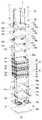
図2は、燃料電池スタック10の構成を示す分解側面図である。図3は、燃料電池スタック10の構成を示す分解斜視図(視線方向:上方から下方)である。図4は、燃料電池スタック10の構成を示す分解斜視図(視線方向:下方から上方)である。 FIG. 2 is an exploded side view showing the configuration of the
燃料電池スタック10は、複数の単セル30、一対の集電体50aならびに集電体50b、一対の絶縁板60aならびに絶縁板60b、複数の流路形成プレート70a,70b,70c,70dおよび一対のエンドプレート80aならびにエンドプレート80bを有する。エンドプレート80aとエンドプレート80bとは、ボルト82によって締結されている。なお、ボルト82とエンドプレート80aとの間は絶縁部材84によって絶縁されている。 The
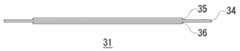
各単セル30は、セパレータ40によって仕切られた、膜電極接合体31、カソード拡散層32およびアノード拡散層33を有し、メタノールと酸素との電気化学反応により電力を発生する。複数の単セル30は、鉛直方向に積層されている。複数の単セル30は、配線(図示せず)により電気的に直列に接続されている。 Each
膜電極接合体31は、電解質膜34と、電解質膜34の上面側に設けられたアノード電極35と、電解質膜34の下面側に設けられたカソード電極36を含む(図5参照)。電解質膜34は、ナフィオン(登録商標)などのプロトン伝導性のポリマーで形成される。アノード電極35には、白金触媒、または白金ルテニウム合金触媒が使用され、カソード電極36には、たとえば白金触媒が使用される。アノード電極35の上に、多孔質性のアノード拡散層37が配設されている。また、カソード電極36の下にカーボンフェルト、カーボンペーパーなどからなるカソード拡散層38が配設されている。 The
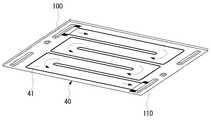
図6に示すように、セパレータ40の下面側に液体燃料流路41が設けられている。液体燃料流路41の入口は燃料供給用マニホールド100と連通し、液体燃料流路41の出口は燃料排出用マニホールド110と連通している。 As shown in FIG. 6, a
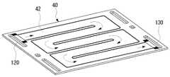
また、図7に示すように、セパレータ40の上面側に酸化剤流路42が形成されている。酸化剤流路42の入口は、酸化剤供給用マニホールド120と連通し、酸化剤流路42の出口は、酸化剤排出用マニホールド130と連通している。 Further, as shown in FIG. 7, an
なお、図2に示すように、膜電極接合体31の上面と、膜電極接合体31の上面側に設けられたセパレータ40との間、および膜電極接合体31の下面と、膜電極接合体31の下面側に設けられたセパレータ40との間には、それぞれパッキンなどの封止部材39が設けられている。封止部材39により、各単セル30からメタノール水溶液および空気が漏出することが抑制されている。封止部材39が液体燃料流路41または酸化剤流路42を横切る場所には、保護板43が設けられている。 2, the gap between the upper surface of the
一対の集電体50a,50bは、複数の単セル30からなる積層体の両側にそれぞれ設けられている。一方の集電体50aが負極として用いられ、他方の集電体50bが正極として用いられる。 The pair of
絶縁板60aは、集電体50aと流路形成プレート70bとの間に配設されている。また、絶縁板60bは、集電体50bと流路形成プレート70cとの間に配設されている。絶縁板60aおよび絶縁板60bは、電気絶縁性の他に、耐熱性、機械的強度、寸法安定性、耐水性などの特性を有することが望ましい。このような特性を具備する材料として、たとえば、エチレンプロピレンゴムなどが挙げられる。 The insulating
流路形成プレート70aおよび流路形成プレート70bは、絶縁板60aとエンドプレート80aとの間に設けられている。流路形成プレート70aおよび流路形成プレート70bには、マニホールド用の貫通穴や溝が形成されている。一方、流路形成プレート70cおよび流路形成プレート70dは、絶縁板60bとエンドプレート80bとの間に設けられている。流路形成プレート70cには、マニホールド用の貫通穴や溝が形成されている。流路形成プレート70cには、マニホールド用の貫通穴や溝が形成されている。流路形成プレート70dには、マニホールド用の貫通穴や溝が形成されている。流路形成プレート70a,70b,70cおよび70dに用いられる材料としては、樹脂、カーボンなどが挙げられる。 The flow
エンドプレート80aおよびエンドプレート80bは、機械的強度を有する材料で形成されている。さらに、エンドプレート80aは、導電性を有する。たとえば、エンドプレート80aおよびエンドプレート80bとして、ステンレス鋼を用いることができ、エンドプレート80aとしてステンレス鋼を用いた場合に、金メッキを施すことによりによりエンドプレート80aに導電性を付与することができる。 The
燃料供給用マニホールド100は、液体燃料が下降する部分(以下、第1の区分という)と、下降した液体燃料を受け止めて、液体燃料が流れる方向を折り返させる接続部分(以下、第2の区分という)と、第2の区分を流通した液体燃料を上方へ送出させるための部分(以下、第3の区分という)とからなり、その入口部分をエンドプレート80a上に有する。燃料供給用マニホールド100を流通する液体燃料は、第3の区分において各単セル30に分配される。 The
燃料供給用マニホールド100の第1の区分は、エンドプレート80a、流路形成プレート70a、流路形成プレート70b、絶縁板60a、各セパレータ40、各膜電極接合体31、絶縁板60bおよび流路形成プレート70cにそれぞれ設けられた貫通穴を連結することにより形成されている。燃料供給用マニホールド100の第2の区分は、流路形成プレート70cおよび流路形成プレート70dにそれぞれ設けられた溝71、溝72によって形成されている。また、燃料供給用マニホールド100の第3の区分は、流路形成プレート70c、各セパレータ40および各膜電極接合体31にそれぞれ設けられた貫通穴を連結することにより形成されている。 The first section of the
燃料排出用マニホールド110は、その出口部分をエンドプレート80a上に有する。燃料排出用マニホールド110は、各セパレータ40、各膜電極接合体31、絶縁板60a、流路形成プレート70b、流路形成プレート70aおよびエンドプレート80aにそれぞれ設けられた貫通穴を連結することにより形成されている。 The
酸化剤供給用マニホールド120は、その入口部分をエンドプレート80a上に有する。酸化剤供給用マニホールド120は、エンドプレート80a、流路形成プレート70a、流路形成プレート70b、絶縁板60a、各セパレータ40および各膜電極接合体31にそれぞれ設けられた貫通穴を連結することにより形成されている。 The
酸化剤排出用マニホールド130は、反応後の空気、反応によって生じた水(以下、排液ガスという)が下降する部分(以下、第4の区分という)と、下降した排液ガスを受け止めて、排液ガスが流れる方向を折り返させる接続部分(以下、第5の区分という)と、第5の区分を流通した排液ガスを上方へ送出させるための部分(以下、第6の区分という)とからなり、その出口部分をエンドプレート80a上に有する。 The
酸化剤排出用マニホールド130の第4の区分は各セパレータ40、各膜電極接合体31、絶縁板60b、流路形成プレート70cにそれぞれ設けられた貫通穴を連結することにより形成されている。酸化剤排出用マニホールド130の第5の区分は流路形成プレート70cおよび流路形成プレート70dにそれぞれ設けられた溝73、溝74によって形成されている。また、酸化剤排出用マニホールド130の第6の区分は、流路形成プレート70c、各セパレータ40、各膜電極接合体31、絶縁板60a、流路形成プレート70b、流路形成プレート70aおよびエンドプレート80aにそれぞれ設けられた貫通穴を連結することにより形成されている。 The fourth section of the oxidizing
本実施形態では、酸化剤排出用マニホールド130の第6の区分の断面積は、第4の区分の断面積に比べて小さくなっている。これによれば、酸化剤排出用マニホールド130の第6の区分において排液ガスの流速が上昇するため、排液ガスに含まれる生成水を確実かつ速やかに燃料電池スタック10から排出することができる。 In the present embodiment, the cross-sectional area of the sixth section of the oxidizing
以上説明した本実施形態によれば、燃料供給用マニホールド100の入り口部分と燃料排出用マニホールド110の出口部分とがエンドプレート80aにより電気的に接続されている。これにより、燃料電池スタック10から排出された排燃料の電位と、燃料電池スタック10に供給される液体燃料の電位が同等になる。この結果、燃料電池スタック10から排出された排燃料を循環させて燃料電池スタック10に供給する場合に、液体燃料が接触する配管やタンクなどの金属部分の腐食の進行が抑制される。 According to the present embodiment described above, the inlet portion of the
また、本実施形態の燃料電池スタック10では、燃料供給用マニホールド100の入口部分、燃料排出用マニホールド110の出口部分、酸化剤供給用マニホールド120の入口部分および酸化剤排出用マニホールド130の出口部分が同じエンドプレート80aに設けられている。これにより、各マニホールドと接続される配管の経路を一カ所にまとめて単純化することができ、燃料電池システム20の小型化を図ることができる。また、各マニホールドと配管との接続部分が互いに近傍に配設されているため、配管の取り付け作業や、接続状態の確認作業を容易に行うことができる。 In the
本発明は、上述の実施の形態に限定されるものではなく、当業者の知識に基づいて各種の設計変更等の変形を加えることも可能であり、そのような変形が加えられた実施の形態も本発明の範囲に含まれうるものである。 The present invention is not limited to the above-described embodiments, and various modifications such as design changes can be added based on the knowledge of those skilled in the art. Embodiments to which such modifications are added Can also be included in the scope of the present invention.
例えば、上述の実施の形態では、燃料供給用マニホールド100の入り口部分と燃料排出用マニホールド110の出口部分とがエンドプレート80aにより電気的に接続されているが、これに限られない。たとえば、燃料供給用マニホールド100の入り口部分と燃料排出用マニホールド110の出口部分を燃料電池スタック10の側面に配された導電板に形成してもよい。 For example, in the above-described embodiment, the inlet portion of the
10 燃料電池スタック、20 燃料電池システム、30 単セル、31 膜電極接合体、40 セパレータ、50a,50b 集電体、70a,70b,70c,70d 流路形成プレート、80a,80b エンドプレート、100 燃料供給用マニホールド、110 燃料排出用マニホールド、120 酸化剤供給用マニホールド、130 酸化剤排出用マニホールド。
DESCRIPTION OF
Claims (1)
Translated fromJapanese前記燃料供給用マニホールドの入口部分および燃料排出用マニホールドの出口部分が、前記複数のセルを集電体と絶縁体を介して挟持する一対のエンドプレートのうち、複数のセルに対して上側に設けられている導電性を有するエンドプレートに配設され
燃料供給用マニホールドは、液体燃料が下降する第1の区分と、下降した液体燃料を受け止めて、液体燃料が流れる方向を折り返させる第2の区分と、第2の区分を流通した液体燃料を上方へ送出させるための第3の区分とからなり、燃料供給用マニホールドを流通する液体燃料は第3の区分において各単セルに分配されていることを特徴とする燃料電池スタック。
A fuel cell stack in which a plurality of cells that generate power using liquid fuel and an oxidantare stacked in thevertical direction, and an inlet portion of a fuel supply manifold for distributing the liquid fuel to each cell; The outlet part of the fuel discharge manifold for discharging the exhaust fuel discharged from each cell is electrically connected,
The inlet portion of the fuel supply manifold and the outlet portion of the fuel discharge manifold are provided above the plurality of cells of the pair of end plates that sandwich the plurality of cells through the current collector and the insulator. The fuel supply manifold isdisposed on the conductive end plate and has a first section where the liquid fuel descends, and receives the lowered liquid fuel and turns the direction in which the liquid fuel flows. It consists of a second section and a third section for sending the liquid fuel flowing through the second section upward, and the liquid fuel flowing through the fuel supply manifold is distributed to each single cell in the third section. A fuel cellstack characterized by being made.
Priority Applications (4)
| Application Number | Priority Date | Filing Date | Title |
|---|---|---|---|
| JP2006054020AJP4489036B2 (en) | 2006-02-28 | 2006-02-28 | Fuel cell stack |
| CNB2007100051041ACN100544091C (en) | 2006-02-28 | 2007-02-09 | Fuel cell stack |
| KR1020070019310AKR100840111B1 (en) | 2006-02-28 | 2007-02-27 | Fuel cell stack |
| US11/711,727US7867665B2 (en) | 2006-02-28 | 2007-02-28 | Fuel cell stack |
Applications Claiming Priority (1)
| Application Number | Priority Date | Filing Date | Title |
|---|---|---|---|
| JP2006054020AJP4489036B2 (en) | 2006-02-28 | 2006-02-28 | Fuel cell stack |
Publications (2)
| Publication Number | Publication Date |
|---|---|
| JP2007234379A JP2007234379A (en) | 2007-09-13 |
| JP4489036B2true JP4489036B2 (en) | 2010-06-23 |
Family
ID=38444389
Family Applications (1)
| Application Number | Title | Priority Date | Filing Date |
|---|---|---|---|
| JP2006054020AExpired - Fee RelatedJP4489036B2 (en) | 2006-02-28 | 2006-02-28 | Fuel cell stack |
Country Status (4)
| Country | Link |
|---|---|
| US (1) | US7867665B2 (en) |
| JP (1) | JP4489036B2 (en) |
| KR (1) | KR100840111B1 (en) |
| CN (1) | CN100544091C (en) |
Families Citing this family (8)
| Publication number | Priority date | Publication date | Assignee | Title |
|---|---|---|---|---|
| US8277964B2 (en) | 2004-01-15 | 2012-10-02 | Jd Holding Inc. | System and method for optimizing efficiency and power output from a vanadium redox battery energy storage system |
| US8097378B2 (en)* | 2009-03-11 | 2012-01-17 | Bloom Energy Corporation | Stack seal interface adapter |
| US10651492B2 (en)* | 2010-06-22 | 2020-05-12 | Vrb Energy Inc. | Integrated system for electrochemical energy storage system |
| US8709629B2 (en) | 2010-12-22 | 2014-04-29 | Jd Holding Inc. | Systems and methods for redox flow battery scalable modular reactant storage |
| US10141594B2 (en) | 2011-10-07 | 2018-11-27 | Vrb Energy Inc. | Systems and methods for assembling redox flow battery reactor cells |
| US9853454B2 (en) | 2011-12-20 | 2017-12-26 | Jd Holding Inc. | Vanadium redox battery energy storage system |
| CN104170144B (en)* | 2012-01-25 | 2017-05-31 | 西门子公司 | For the heap of energy storage |
| JP6014571B2 (en)* | 2012-12-07 | 2016-10-25 | 本田技研工業株式会社 | Fuel cell stack |
Family Cites Families (13)
| Publication number | Priority date | Publication date | Assignee | Title |
|---|---|---|---|---|
| JPH06176790A (en)* | 1992-12-02 | 1994-06-24 | Mitsubishi Heavy Ind Ltd | Fuel cell module |
| EP0981175B1 (en)* | 1998-08-20 | 2012-05-02 | Panasonic Corporation | Polymer electrolyte fuel cell stack |
| JP3454722B2 (en) | 1998-08-20 | 2003-10-06 | 松下電器産業株式会社 | Polymer electrolyte fuel cell |
| JP4862206B2 (en)* | 1999-10-08 | 2012-01-25 | トヨタ自動車株式会社 | Fuel cell |
| EP1320140A4 (en)* | 2000-08-16 | 2007-10-10 | Matsushita Electric Industrial Co Ltd | FUEL CELL |
| KR100397611B1 (en)* | 2001-03-31 | 2003-09-17 | 삼성전자주식회사 | Proton exchange fuel cell stack |
| US20060166053A1 (en)* | 2001-11-21 | 2006-07-27 | Badding Michael E | Solid oxide fuel cell assembly with replaceable stack and packet modules |
| KR20030091485A (en)* | 2002-05-28 | 2003-12-03 | 삼성에스디아이 주식회사 | Fuel supplying method of direct liquid feed fuel cell and fuel cell apparatus adopting the same |
| JP2004047211A (en) | 2002-07-10 | 2004-02-12 | Nissan Motor Co Ltd | Fuel cell system |
| US7063912B2 (en) | 2002-11-01 | 2006-06-20 | Deere & Company | Fuel cell assembly system |
| JP4630529B2 (en) | 2003-06-13 | 2011-02-09 | 本田技研工業株式会社 | Fuel cell system |
| KR100528339B1 (en) | 2003-10-01 | 2005-11-15 | 삼성에스디아이 주식회사 | Direct liquid feed fuel cell stack |
| JP2005141935A (en) | 2003-11-04 | 2005-06-02 | Hitachi Cable Ltd | Fuel cell stack |
- 2006
- 2006-02-28JPJP2006054020Apatent/JP4489036B2/ennot_activeExpired - Fee Related
- 2007
- 2007-02-09CNCNB2007100051041Apatent/CN100544091C/ennot_activeExpired - Fee Related
- 2007-02-27KRKR1020070019310Apatent/KR100840111B1/ennot_activeExpired - Fee Related
- 2007-02-28USUS11/711,727patent/US7867665B2/ennot_activeExpired - Fee Related
Also Published As
| Publication number | Publication date |
|---|---|
| CN100544091C (en) | 2009-09-23 |
| JP2007234379A (en) | 2007-09-13 |
| KR100840111B1 (en) | 2008-06-19 |
| US7867665B2 (en) | 2011-01-11 |
| US20070202385A1 (en) | 2007-08-30 |
| CN101030648A (en) | 2007-09-05 |
| KR20070089613A (en) | 2007-08-31 |
Similar Documents
| Publication | Publication Date | Title |
|---|---|---|
| CN110129818B (en) | Proton exchange membrane water electrolyzer | |
| JP4489036B2 (en) | Fuel cell stack | |
| US7169496B2 (en) | Fuel Cell | |
| JP2011086549A (en) | Fuel cell system | |
| US20070122677A1 (en) | Fuel cell system | |
| US11978933B2 (en) | Compression apparatus | |
| JP2007234315A (en) | Fuel cell | |
| JP5312830B2 (en) | Fuel cell and fuel cell vehicle | |
| KR20100033618A (en) | Current collector and stack of fuel cell | |
| JP4643393B2 (en) | Fuel cell | |
| KR100556814B1 (en) | Stack of fuel cell | |
| KR101008738B1 (en) | Fuel cell assembly | |
| JP4643394B2 (en) | Fuel cell | |
| JP4204526B2 (en) | Fuel cell system | |
| JP2014002920A (en) | Fuel cell | |
| KR100859457B1 (en) | 스택 Stack structure of fuel cell using compound as fuel | |
| KR100830939B1 (en) | 수소 Hydrogen gas removal device of fuel cell using compound as fuel | |
| KR100829428B1 (en) | Fuel tanks of fuel cells | |
| WO2022050150A1 (en) | Fuel battery | |
| JP2013105602A (en) | Fuel cell stack and fuel cell system | |
| CN100399618C (en) | Fuel cell stack structure | |
| KR100446781B1 (en) | Electrode structure for fuel cell | |
| KR20060018476A (en) | Fuel cell generated by high concentration of oxygen | |
| JP2007242459A (en) | Fuel cell system | |
| KR20040003660A (en) | Stack structure of fuel cell |
Legal Events
| Date | Code | Title | Description |
|---|---|---|---|
| A521 | Request for written amendment filed | Free format text:JAPANESE INTERMEDIATE CODE: A523 Effective date:20070626 | |
| A621 | Written request for application examination | Free format text:JAPANESE INTERMEDIATE CODE: A621 Effective date:20070810 | |
| A131 | Notification of reasons for refusal | Free format text:JAPANESE INTERMEDIATE CODE: A131 Effective date:20091006 | |
| A521 | Request for written amendment filed | Free format text:JAPANESE INTERMEDIATE CODE: A523 Effective date:20091111 | |
| A131 | Notification of reasons for refusal | Free format text:JAPANESE INTERMEDIATE CODE: A131 Effective date:20100202 | |
| A521 | Request for written amendment filed | Free format text:JAPANESE INTERMEDIATE CODE: A523 Effective date:20100205 | |
| TRDD | Decision of grant or rejection written | ||
| A01 | Written decision to grant a patent or to grant a registration (utility model) | Free format text:JAPANESE INTERMEDIATE CODE: A01 Effective date:20100302 | |
| A01 | Written decision to grant a patent or to grant a registration (utility model) | Free format text:JAPANESE INTERMEDIATE CODE: A01 | |
| A61 | First payment of annual fees (during grant procedure) | Free format text:JAPANESE INTERMEDIATE CODE: A61 Effective date:20100330 | |
| FPAY | Renewal fee payment (event date is renewal date of database) | Free format text:PAYMENT UNTIL: 20130409 Year of fee payment:3 | |
| FPAY | Renewal fee payment (event date is renewal date of database) | Free format text:PAYMENT UNTIL: 20130409 Year of fee payment:3 | |
| LAPS | Cancellation because of no payment of annual fees |