JP4487359B2 - Stereo microscope and dark field illumination device - Google Patents
Stereo microscope and dark field illumination deviceDownload PDFInfo
- Publication number
- JP4487359B2 JP4487359B2JP37444999AJP37444999AJP4487359B2JP 4487359 B2JP4487359 B2JP 4487359B2JP 37444999 AJP37444999 AJP 37444999AJP 37444999 AJP37444999 AJP 37444999AJP 4487359 B2JP4487359 B2JP 4487359B2
- Authority
- JP
- Japan
- Prior art keywords
- light
- optical axis
- reflecting member
- dark field
- annular
- Prior art date
- Legal status (The legal status is an assumption and is not a legal conclusion. Google has not performed a legal analysis and makes no representation as to the accuracy of the status listed.)
- Expired - Lifetime
Links
Images


Classifications
- G—PHYSICS
- G02—OPTICS
- G02B—OPTICAL ELEMENTS, SYSTEMS OR APPARATUS
- G02B21/00—Microscopes
- G02B21/06—Means for illuminating specimens
- G02B21/08—Condensers
- G02B21/10—Condensers affording dark-field illumination
- G—PHYSICS
- G02—OPTICS
- G02B—OPTICAL ELEMENTS, SYSTEMS OR APPARATUS
- G02B21/00—Microscopes
- G02B21/18—Arrangements with more than one light path, e.g. for comparing two specimens
- G02B21/20—Binocular arrangements
- G02B21/22—Stereoscopic arrangements
Landscapes
- Physics & Mathematics (AREA)
- Chemical & Material Sciences (AREA)
- Analytical Chemistry (AREA)
- General Physics & Mathematics (AREA)
- Optics & Photonics (AREA)
- Microscoopes, Condenser (AREA)
- Optical Elements Other Than Lenses (AREA)
Description
Translated fromJapanese【0001】
【発明の属する技術分野】
本発明は、実体顕微鏡およびそれに使用される暗視野照明装置に関するものである。
【0002】
【従来の技術】
実体顕微鏡装置を用いて落射照明や透過照明で被検体を観察する際に、被検体が透明な生物標本である場合や宝石の傷等微細構造である場合、背景とのコントラストが得にくかったり、微細構造を識別しにくいことがある。このような場合には、暗視野照明が用いられる。暗視野照明は、照明光束を観察光学系に直接入射させず、被検体による散乱光や回折光のみを観察光として用い、被検体周辺を暗背景となるようにすることにより、透明な被検体や微細構造を観察しやすい像を得ることができる。
【0003】
従来の暗視野照明装置としては、バレル型トロイド鏡の中心に光源を配置し、バレル型トロイド鏡と光源との間に光散乱構造体を配置した装置が例えば特開昭61−102618号公報に記載されている。また、特公平5−16567号公報には、光源の周りに環状反射部材を配置し、この環状反射部材に光軸に平行な方向に無数のヘアラインを刻設した暗視野照明装置が開示されている。また、特開平11−153755号公報には、光源の周りに環状反射部材を配置し、この環状反射部材に光軸に平行な方向に長手方向をもつ円筒状曲面部を多数形成した暗視野照明装置が開示されている。これらはいずれも、光散乱構造体やヘアラインや円筒状曲面部によって光源の出射した光を散乱させて試料に照射することにより、むらのない照明を実現しようとしている。
【0004】
【発明が解決しようとする課題】
上記従来の暗視野照明装置は、散乱光で被検体を照明する構成であるため、照明むらを生じにくいという利点があるが、その反面、光源が出射した光の一部しか被検体に入射しないため、被検体に入射する照明光量はあまり大きくできない。そのため、被検体として、光の散乱効率や回折効率が小さいものを従来の散乱型の暗視野照明で観察しようとすると、生じる散乱光や回折光の光量が少ないために、暗い像しか得られず、観察しづらくなる。
【0005】
本発明は、光源から出射された光を高効率で被検体に照射することができ、しかも照明むらの少ない暗視野照明装置を有する実体顕微鏡を提供することを目的とする。
【0006】
【課題を解決するための手段】
上記目的を達成するために、本願によれば以下のような暗視野照明装置が提供される。
【0007】
すなわち、対物レンズ(5)と、被検体を搭載するための被検体搭載面(4)と、前記被検体搭載面(4)を挟んで前記対物レンズ(5)と対向する位置に配置された暗視野照明装置とを有し、
前記暗視野照明装置は、前記対物レンズ(5)の光軸(101)上に配置された、光源(1)と、前記光源(1)からの光を内側面で反射するための環状反射部材(2)と、前記環状反射部材(2)で反射された光束の一部を遮る遮光板(3)とを備え、
前記環状反射部材(2)の内側面は、前記光軸(101)に垂直な面内において予め定められた曲率半径の凹形状を有する複数の反射面(2a〜2g)を、前記光軸(101)を中心に環状に配置した形状であり、前記光軸(101)は、前記複数の反射面(2a〜2g)とその曲率中心との間に位置することを特徴とする実体顕微鏡を提供する。
【0008】
なお、上記記載において各構成要件の後に括弧書きで示した符号は、後述する実施の形態でその構成要件に対応する構成の符号であるが、その構成要件を実施の形態の符号の構成に限定するものではない。
【0009】
【発明の実施の形態】
本発明の一実施の形態について図面を用いて説明する。
(実施の形態1)
本発明の第1の実施の形態の暗視野照明装置を備えた実体顕微鏡について説明する。
【0010】
本実施の実体顕微鏡は、図5に示したように、暗視野照明装置を内蔵するベース51、対物レンズ5、変倍レンズ鏡筒53、接眼レンズ54、焦点合わせ装置55を有している。ベース51の上面の一部には透明部材をはめ込んだ窓60が設けられており、この窓60の上面が被検体を搭載する被検面4になっている。
【0011】
変倍レンズ鏡筒53の内部には左眼用、右眼用の変倍レンズ群(不図示)および結像レンズ群(不図示)がそれぞれ配置され、鏡筒の外側には変倍ノブ56が配置されている。変倍レンズ群には、ズーム用可動レンズが含まれており、変倍ノブ56の回転によりこのズーム用可動レンズが光軸方向に沿って移動するように構成されている。また、変倍レンズ群には可変絞りが含まれており、変倍レンズ鏡筒53には、この可変絞りを調節するスライダスイッチ59が取り付けられている。
【0012】
また、焦点合わせ装置55は、焦点合わせノブ57と、ノブ57の回転に伴い変倍レンズ鏡筒53を軸58に沿って上下動させる機構部(不図示)とを有している。対物レンズ5および接眼レンズ54は、変倍レンズ鏡筒53に固定されており、変倍レンズ鏡筒53と一体に上下動する。
【0013】
ベース51の内部に配置された暗視野照明装置は、図1および図2に示すように光源1と、環状反射部材2と、遮光部材3とを含んでいる。光源1は、対物レンズ5の光軸101上に配置されている。環状反射部材2は、内側面が、同じ形状の7つの反射面2a〜2gを環状に配置した多角形の反射面になっている(図2)。環状反射部材2の中心は、対物レンズ5の光軸101と一致するように配置されている。
【0014】
環状反射部材2の反射面2a〜2gは、光軸101に垂直な面において曲率半径RHの凹面に形成されている。多角形の反射面2a〜2gに外接する円の半径をrとした場合、反射面の曲率半径RHは、RH≧rとなるように定められている(図2)。よって、光軸101(環状反射部材2の中心)は、反射面2aの凹面の曲率中心位置Oaと反射面2aとの間に位置する。他の反射面2b〜2gについても、光軸101は、反射面2b〜2gとその曲率中心位置よりも反射面2b〜2g側に位置する。
【0015】
また、環状反射部材2の反射面2a〜2gは、光軸101を含む入射面方向については一定の形状であり(図1)、この方向については凹面ではない。
【0016】
遮光部材3は、半径RSの円形の板状部材であり、中心が光軸101に一致するように環状反射部材2の内側に配置されている。遮光部材3は、光源1から出射された光束および環状反射部材2の反射面2a〜2gにより反射された光束のうち、対物レンズ5に直接入射する光束を遮るように、環状反射部材2の長さL、対物レンズ5の最小作動距離WD、および、対物レンズ5の最大開口角Ψを考慮してその半径RSが定められている。
【0017】
このような暗視野照明装置において、光源1は電源装置52に接続され、電流を供給される。これにより光源1から出射された照明光は、図1のように環状反射部材2の反射面2a〜2gにより正反射され、被検面4に入射する。このとき光軸101(環状反射部材2の中心)が反射面2aの凹面の曲率中心位置Oaと反射面2aとの間に位置するように配置されているため、被検面4の上方から見た場合、図2のように、反射面2aにより正反射された光は幅φを有する光束となって被検面4に入射する。同様に反射面2b〜2gで正反射された光も幅φを有する光束となってそれぞれ被検面4に入射する。よって、図6に示したように、被検面4上には、光軸101を中心に7つの光束が重なりあって照射され、重なり合う領域は7角形の領域ABCDEFGHIJKIMNとなる。この7角形の領域A〜Nの内部は、7つの光束が重なりあっているため、もっとも明るく、しかもほとんど照明むらがない。よって、必要とされる照明範囲、すなわち被検面4上での対物レンズ5の最大視野範囲が、この7角形の領域A〜Nの内接円となるように、環状反射部材2の反射面2a〜2gの大きさおよび曲率RH等を定めることにより、正反射光により、むらのない照明を実現することができる。
【0018】
また、図1のように光軸101を含む面においては、環状反射部材2による正反射光は、遮光部材3に光束の一部が遮られることにより、斜め方向から被検面4に入射し、照明光が対物レンズ5に直接入射しない。これにより暗視野照明を実現することができる。また、反射面2aによる反射光束の被検面4を横切る際の径Tが、上記7角形の領域A〜Nの内接円の直径φと同じか、もしくはそれ以上の大きさになるように、環状反射部材2の半径r、長さLおよび遮光部材3の径RSを設計しておく。他の反射面2b〜2gについても同様にする。これにより、正反射光により、むらのない照明を実現することができる。
【0019】
よって、被検面4の上記7角形の領域A〜Nの直径φの内接円の内部を照明範囲として、この照明範囲内に被検体を搭載することにより、被検体によって生じた散乱光および回折光のみを対物レンズ5に入射させることができる。これら散乱光、回折光は、変倍レンズ群および結像レンズ群により結像され、この像を接眼レンズ54により観察することにより、暗視野照明像を観察することができる。また、焦点位置合わせは、ノブ57の回転によって、変倍レンズ鏡筒53を上下させることにより行われる。また、ノブ56の回転により所望の倍率に変倍できる。
【0020】
本実施の形態の暗視野照明装置は、正反射光で被検体をむらなく照明することを可能にしたため、散乱光で照明する場合と比較して、照明効率がよく、被検体に入射する光量を大きくすることができる。このため、被検体が散乱光および回折光の発生効率が小さいものであっても、生じる散乱光および回折光の光量を大きくでき、明るい暗視野像を得ることができる。これにより、微細な構造や透明な被検体を観察しやすいという効果が得られる。また、散乱光で照明する場合と比較して、対物レンズ5に入射する迷光が少ないため、暗視野効果が減じられることもない。
【0021】
なお、図2、図6のように被検体4を上面からみた場合の各反射面2a〜2gの反射光束が、平行かもしくは広がりながら被検面4に入射するように環状反射部材2を構成すると、照明範囲の直径φを大きく確保することが容易になる。反射光束が平行かもしくは広がりながら入射するようにするには、反射面2a〜2gの曲率半径RHが下記(1)式を満たすように設計する。
【0022】
RH≧φ/(2tan(π/(2n))) ・・・(1)
ただし、nは環状反射部材2を構成する反射面の数であり、ここではn=7である。
【0023】
なお、本実施の形態では、対物レンズ5の最大視野、すなわち必要とされる最大照明範囲が被検面4上で直径32mmであるので、φ=32mmとし、上記(1)式から計算したところ、RH≧70.1mmとなる。光源1の取り付け誤差からくる環状反射部材2の光軸101からの偏心を考慮して、本実施の形態ではRH=75mmとした。これにより、図1,図2に示したように、照明光が対物レンズに直接入射しない暗視野照明の条件を確保しながら、必要とされる最大照明範囲φ全体を照明できる。
【0024】
また、照明むらをよりいっそう少なくし、高効率で被検体に照射するためには、図2、図6のように被検体4を上面からみた場合の各反射面2a〜2gの反射光束がほぼ平行光束であることが望ましい。これは、凹面の反射面2a〜2gの焦点位置を光軸101が通るように、反射面2a〜2gの曲率半径RHおよび環状反射部材の半径rを設計することに実現することができる。
【0025】
なお、本実施の形態では、環状反射部材2の反射面の数を7にしているが、反射面の数は7に限定されるわけではなく、3以上であればいくつに設定することも可能である。
【0026】
また、上記実施の形態では、実体顕微鏡の照明装置として暗視野照明装置のみについて説明したが、落射照明装置や透過照明装置を暗視野照明装置と共に備える構成にすることももちろん可能である。
(実施の形態2)
本発明の第2の実施の形態の暗視野照明装置を備えた実体顕微鏡について説明する。第2の実施の形態の実体顕微鏡は、暗視野照明装置の構成が第1の実施の形態とは異なっている。これ以外の全体の構成は第1の実施の形態と同じであるので説明を省略する。
【0027】
本実施の形態の暗視野照明装置は、図3に示すように、反射面2a〜2gが、光軸101を含む入射面方向においても曲率半径RVの凹面を有している。しかも、光軸101を含む入射面方向における凹面の曲率中心Ovの位置は、環状反射部材2の光源1側端面よりも光源1側に位置するように定められている。よって、環状反射部材2の内径は、光源1側端部の方が被検面4側端部よりも大きくなっている。
【0028】
なお、環状反射部材2は、光軸101に垂直な面においては、第1の実施の形態と同様に曲率半径RHの凹面に形成されている。
【0029】
このように、第2の実施の形態では、反射面2a〜2gが光軸101を含む入射面方向においても凹面の曲率を有するように構成していることにより、図3のように光軸101を含む面において、反射面2aによる反射光束の発散角度が、図1の第1の実施の形態の場合の発散角度よりも小さくなる。また、凹面の曲率中心Ovの位置は、環状反射部材2の光源1側端面よりも光源1側に位置するため、反射光束と被検面4とのなす最大角度θも、図3のように、図1の第1の実施の形態の場合の最大角度θよりも小さくなる
したがって、第2の実施の形態の暗視野照明装置は、対物レンズ5の最小作動距離WDが短い場合でも照明光が直接対物レンズ5に入射しない構成を、環状反射部材2の長さLを短くすることなく実現できるため、高倍率な対物レンズ5の実体顕微鏡に、照明強度が大きな暗視野照明を提供することができる。
【0030】
第2の実施の形態の暗視野照明装置において、照明光が直接対物レンズ5に入射しないようにするためには、最大角度θ、曲率半径RVは下記(2)式および(3)式を満足するように設計する。ただし、Ψは、対物レンズ5の最大開口角である。
【0031】
【数1】
【0032】
【数2】
【0033】
また、第2の実施の形態の実体顕微鏡の暗視野照明装置は、環状反射部材2の光源1側端部の径が被検面4側端部の径よりも大きくなっているため、環状反射部材をモールド型を用いて製造する際に、型を抜くために必要な抜き勾配が確保できるという効果も得られる。よって、割型等を用いることなく、容易にかつ低コストに環状反射部材を製造することが可能である。
【0034】
上述してきたように、第1及び第2の実施の形態の実体顕微鏡は、正反射光により照明むらの少ない暗視野照明を実現することができるため、照明光量を増加させることができ、散乱光量及び回折光量を増やして、明るい暗視野像を得ることができる。これにより、微細構造や透明な被検体を精度よく観察することが可能になる。
【0035】
【発明の効果】
上述してきたように、本願の請求項1に記載の発明によれば、光源から出射された光を高効率で被検体に照射することができ、しかも照明むらの少ない暗視野照明装置を備えた実体顕微鏡を提供することができる。
【0036】
また、本願の請求項2に記載の発明によれば、光束が重なり合う領域の径が、必要とされる照明範囲の径以上であるため、必要とされる照明範囲全体を少ない照明むらで照明することのできる実体顕微鏡を提供することができる。
【0037】
また、本願の請求項3に記載の発明によれば、環状反射部材の各反射面からの反射光束が平行光束もしくは拡散光束であるため、照明範囲の径を大きく確保しやすい実体顕微鏡を提供することができる。
【0038】
また、本願の請求項4に記載の発明によれば、対物レンズの最小作動距離が小さくても、環状反射部材の長さを維持でき、大きな光量で暗視野照明することのできる実体顕微鏡を提供することができる。
【0039】
また、本願の請求項5に記載の発明によれば、光源から出射された光を高効率で被検体に照射することができ、しかも照明むらの少ない暗視野照明装置を提供することができる。
【図面の簡単な説明】
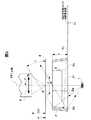
【図1】本発明の第1の実施の形態の実体顕微鏡の暗視野照明装置を、光軸101を含む面からみた構成および光束を示す説明図。
【図2】図1の暗視野照明装置をA方向からみた矢視図。
【図3】本発明の第2の実施の形態の実体顕微鏡の暗視野照明装置を、光軸101を含む面からみた構成および光束を示す説明図。
【図4】図3の暗視野照明装置をB方向からみた矢視図。
【図5】本発明の第1の実施の形態の実体顕微鏡の斜視図。
【図6】本発明の第1の実施の形態の実体顕微鏡の暗視野照明装置において、環状反射部材2の反射面2a〜2gで反射された光束の被検面上で重なり合いを、光軸101に垂直な方向からみた状態で説明する説明図。
【符号の説明】
1…光源、2…環状反射部材、2a〜2g…反射面、3…遮光板、4…被検面、5…対物レンズ、51…ベース、52…照明電源、53…変倍レンズ鏡筒、54…接眼レンズ、55…焦点合わせ装置、56…変倍ノブ、57…焦点合わせノブ、58…軸、59…可変絞り調節スライドスイッチ、60…窓。[0001]
BACKGROUND OF THE INVENTION
The present invention relates to a stereomicroscope and a dark field illumination device used therefor.
[0002]
[Prior art]
When observing a subject with epi-illumination or transmitted illumination using a stereomicroscope device, if the subject is a transparent biological specimen or a fine structure such as a scratch on a gemstone, contrast with the background is difficult to obtain, It may be difficult to identify the microstructure. In such cases, dark field illumination is used. Dark field illumination does not cause the illumination beam to directly enter the observation optical system, but uses only scattered light or diffracted light from the subject as observation light, and makes the subject periphery a dark background. And an image that allows easy observation of the fine structure can be obtained.
[0003]
As a conventional dark field illumination device, a device in which a light source is arranged at the center of a barrel type toroid mirror and a light scattering structure is arranged between the barrel type toroid mirror and the light source is disclosed in, for example, JP-A-61-102618. Are listed. Japanese Patent Publication No. 5-16567 discloses a dark field illumination device in which an annular reflecting member is arranged around a light source, and an infinite number of hairlines are engraved in the annular reflecting member in a direction parallel to the optical axis. Yes. Japanese Patent Laid-Open No. 11-153755 discloses a dark field illumination in which an annular reflecting member is arranged around a light source and a large number of cylindrical curved portions having a longitudinal direction in a direction parallel to the optical axis are formed on the annular reflecting member. An apparatus is disclosed. All of these are intended to realize uniform illumination by scattering light emitted from a light source by a light scattering structure, a hairline, or a cylindrical curved surface portion and irradiating the sample.
[0004]
[Problems to be solved by the invention]
Since the conventional dark field illumination device is configured to illuminate the subject with scattered light, there is an advantage that uneven illumination is less likely to occur, but on the other hand, only part of the light emitted from the light source is incident on the subject. For this reason, the amount of illumination light incident on the subject cannot be increased too much. For this reason, when an object with low light scattering efficiency or diffraction efficiency is observed with conventional scattering-type dark field illumination, only a dark image can be obtained because the amount of scattered light and diffracted light generated is small. It becomes difficult to observe.
[0005]
An object of the present invention is to provide a stereomicroscope having a dark field illumination device that can irradiate a subject with light emitted from a light source with high efficiency and has little illumination unevenness.
[0006]
[Means for Solving the Problems]
In order to achieve the above object, according to the present application, the following dark field illumination device is provided.
[0007]
That is, the objective lens (5), the subject mounting surface (4) for mounting the subject, and the objective lens (5) are arranged at positions facing the objective lens (5) across the subject mounting surface (4). A dark field illumination device,
The dark field illumination device includes a light source (1) disposed on the optical axis (101) of the objective lens (5), and an annular reflecting member for reflecting light from the light source (1) on an inner surface. (2) and a light shielding plate (3) that blocks a part of the light beam reflected by the annular reflecting member (2),
The inner surface of the annular reflecting member (2) has a plurality of reflecting surfaces (2a to 2g) having a concave shape with a predetermined radius of curvature in a plane perpendicular to the optical axis (101). 101) is provided in the shape of a ring, and the optical axis (101) is located between the plurality of reflecting surfaces (2a to 2g) and the center of curvature. To do.
[0008]
In the above description, the reference numerals in parentheses after each constituent element are reference numerals corresponding to the constituent element in the embodiment described later, but the constituent element is limited to the configuration of the reference numeral in the embodiment. Not what you want.
[0009]
DETAILED DESCRIPTION OF THE INVENTION
An embodiment of the present invention will be described with reference to the drawings.
(Embodiment 1)
A stereomicroscope equipped with the dark field illumination device of the first embodiment of the present invention will be described.
[0010]
As shown in FIG. 5, the stereomicroscope of the present embodiment includes a
[0011]
Inside the
[0012]
The focusing
[0013]
The dark field illumination device arranged inside the
[0014]
The reflecting
[0015]
Further, the reflecting
[0016]
The
[0017]
In such a dark field illumination device, the
[0018]
In addition, on the surface including the
[0019]
Therefore, the inside of the inscribed circle with the diameter φ of the heptagonal regions A to N of the
[0020]
Since the dark field illumination device of the present embodiment can illuminate the subject evenly with specular reflection light, the illumination efficiency is better than when illuminating with scattered light, and the amount of light incident on the subject. Can be increased. For this reason, even if the subject has a low generation efficiency of scattered light and diffracted light, the amount of generated scattered light and diffracted light can be increased, and a bright dark field image can be obtained. Thereby, the effect that it is easy to observe a fine structure and a transparent subject is acquired. Further, since the stray light incident on the
[0021]
2 and 6, the
[0022]
RH ≧ φ / (2tan (π / (2n))) (1)
However, n is the number of the reflective surfaces which comprise the cyclic | annular
[0023]
In the present embodiment, the maximum field of view of the
[0024]
Further, in order to further reduce illumination unevenness and irradiate the subject with high efficiency, the reflected light fluxes of the reflecting
[0025]
In the present embodiment, the number of reflecting surfaces of the
[0026]
In the above embodiment, only the dark field illumination device has been described as the illumination device of the stereomicroscope. However, it is of course possible to adopt a configuration in which the epi-illumination device and the transmission illumination device are provided together with the dark field illumination device.
(Embodiment 2)
A stereomicroscope equipped with the dark field illumination device of the second embodiment of the present invention will be described. The stereomicroscope according to the second embodiment is different from the first embodiment in the configuration of the dark field illumination device. Since the other overall configuration is the same as that of the first embodiment, the description thereof is omitted.
[0027]
In the dark field illumination device of the present embodiment, as shown in FIG. 3, the reflecting
[0028]
Note that the
[0029]
As described above, in the second embodiment, the reflecting
[0030]
In the dark field illumination device of the second embodiment, in order to prevent the illumination light from directly entering the
[0031]
[Expression 1]
[0032]
[Expression 2]
[0033]
In the dark field illumination device of the stereomicroscope according to the second embodiment, the diameter of the end portion on the
[0034]
As described above, the stereomicroscopes according to the first and second embodiments can realize dark field illumination with less illumination unevenness by specular reflection light, so that the amount of illumination light can be increased and the amount of scattered light can be increased. In addition, a bright dark field image can be obtained by increasing the amount of diffracted light. This makes it possible to accurately observe the fine structure and the transparent subject.
[0035]
【The invention's effect】
As described above, according to the invention described in
[0036]
According to the invention described in
[0037]
Further, according to the invention described in
[0038]
In addition, according to the invention described in
[0039]
In addition, according to the invention described in
[Brief description of the drawings]
FIG. 1 is an explanatory diagram illustrating a configuration and a light beam when a dark field illumination device of a stereomicroscope according to a first embodiment of the present invention is viewed from a plane including an optical axis.
2 is an arrow view of the dark field illumination device of FIG. 1 viewed from the direction A. FIG.
FIG. 3 is an explanatory diagram showing a configuration and a light flux when a dark field illumination device of a stereomicroscope according to a second embodiment of the present invention is viewed from a plane including an
4 is an arrow view of the dark field illumination device of FIG. 3 as seen from the B direction.
FIG. 5 is a perspective view of the stereomicroscope according to the first embodiment of the present invention.
6 shows an
[Explanation of symbols]
DESCRIPTION OF
Claims (5)
Translated fromJapanese前記暗視野照明装置は、前記対物レンズの光軸上に配置された、光源と、前記光源からの光を内側面で反射するための環状反射部材と、前記環状反射部材で反射された光束の一部を遮る遮光板とを備え、
前記環状反射部材の内側面は、前記光軸に垂直な面内において予め定められた曲率半径の凹形状を有する複数の反射面を、前記光軸を中心に環状に配置した形状であり、前記光軸は、前記複数の反射面とその曲率中心との間に位置することを特徴とする実体顕微鏡。An objective lens, a subject mounting surface for mounting the subject, and a dark field illumination device disposed at a position facing the objective lens across the subject mounting surface,
The dark field illumination device includes a light source disposed on the optical axis of the objective lens, an annular reflecting member for reflecting light from the light source on an inner surface, and a light beam reflected by the annular reflecting member. With a shading plate that blocks part of it,
The inner surface of the annular reflecting member has a shape in which a plurality of reflecting surfaces having a concave shape with a predetermined radius of curvature in a plane perpendicular to the optical axis are annularly arranged around the optical axis, A stereomicroscope characterized in that an optical axis is located between the plurality of reflecting surfaces and the center of curvature thereof.
前記環状反射部材の内側面は、前記光軸に垂直な面内において予め定められた曲率半径の凹形状を有する複数の反射面を、前記光軸を中心に環状に配置した形状であり、前記光軸は、前記複数の反射面とその曲率中心との間に位置することを特徴とする暗視野照明装置。A light source disposed on the optical axis of the objective lens, an annular reflecting member for reflecting light from the light source on the inner surface, and a light shielding plate for blocking a part of the light beam reflected by the annular reflecting member Have
The inner surface of the annular reflecting member has a shape in which a plurality of reflecting surfaces having a concave shape with a predetermined radius of curvature in a plane perpendicular to the optical axis are arranged in an annular shape around the optical axis, The dark field illumination device, wherein an optical axis is located between the plurality of reflecting surfaces and a center of curvature thereof.
Priority Applications (2)
| Application Number | Priority Date | Filing Date | Title |
|---|---|---|---|
| JP37444999AJP4487359B2 (en) | 1999-12-28 | 1999-12-28 | Stereo microscope and dark field illumination device |
| US09/748,183US6456431B2 (en) | 1999-12-28 | 2000-12-27 | Stereomicroscope and dark field illumination apparatus |
Applications Claiming Priority (1)
| Application Number | Priority Date | Filing Date | Title |
|---|---|---|---|
| JP37444999AJP4487359B2 (en) | 1999-12-28 | 1999-12-28 | Stereo microscope and dark field illumination device |
Publications (2)
| Publication Number | Publication Date |
|---|---|
| JP2001188177A JP2001188177A (en) | 2001-07-10 |
| JP4487359B2true JP4487359B2 (en) | 2010-06-23 |
Family
ID=18503873
Family Applications (1)
| Application Number | Title | Priority Date | Filing Date |
|---|---|---|---|
| JP37444999AExpired - LifetimeJP4487359B2 (en) | 1999-12-28 | 1999-12-28 | Stereo microscope and dark field illumination device |
Country Status (2)
| Country | Link |
|---|---|
| US (1) | US6456431B2 (en) |
| JP (1) | JP4487359B2 (en) |
Families Citing this family (4)
| Publication number | Priority date | Publication date | Assignee | Title |
|---|---|---|---|---|
| US7344273B2 (en) | 2005-03-22 | 2008-03-18 | Binary Works, Inc. | Ring light with user manipulable control |
| CN104024913A (en) | 2011-12-22 | 2014-09-03 | 松下健康医疗器械株式会社 | Observation System, And Control Method And Program Therefor |
| CN107193107B (en)* | 2017-05-22 | 2019-10-29 | 李卫青 | A kind of clamping of condenser debugging curved reflector tunes device |
| CN110736752B (en)* | 2019-11-11 | 2024-10-01 | 爱丁堡(南京)光电设备有限公司 | Illumination mode, illumination structure and detection device for surface defect detection |
Family Cites Families (7)
| Publication number | Priority date | Publication date | Assignee | Title |
|---|---|---|---|---|
| DE271963C (en)* | ||||
| JPS503355A (en)* | 1973-05-11 | 1975-01-14 | ||
| JPS6090319A (en)* | 1983-10-24 | 1985-05-21 | Olympus Optical Co Ltd | Dark field illuminating device |
| US4575788A (en)* | 1984-04-30 | 1986-03-11 | Ql, Inc. | Segmented luminaire |
| JPS61102618A (en) | 1984-10-23 | 1986-05-21 | ヴィルト ライツ アクチエンゲゼルシャフト | Dark-field lighting apparatus |
| JPH0516567A (en) | 1991-07-08 | 1993-01-26 | Ricoh Co Ltd | Device and method for posttreatment |
| JPH11153755A (en) | 1997-09-19 | 1999-06-08 | Olympus Optical Co Ltd | Dark field illuminator |
- 1999
- 1999-12-28JPJP37444999Apatent/JP4487359B2/ennot_activeExpired - Lifetime
- 2000
- 2000-12-27USUS09/748,183patent/US6456431B2/ennot_activeExpired - Fee Related
Also Published As
| Publication number | Publication date |
|---|---|
| US20010005279A1 (en) | 2001-06-28 |
| JP2001188177A (en) | 2001-07-10 |
| US6456431B2 (en) | 2002-09-24 |
Similar Documents
| Publication | Publication Date | Title |
|---|---|---|
| EP1941313B1 (en) | An optical system for illumination of an evanescent field | |
| US7547874B2 (en) | Single axis illumination for multi-axis imaging system | |
| US7982950B2 (en) | Measuring system for structures on a substrate for semiconductor manufacture | |
| US5162941A (en) | Confocal microscope | |
| EP2136233B1 (en) | Microscope device | |
| JP5999121B2 (en) | Confocal light scanner | |
| EP2093601A1 (en) | Microscope device and image processing method | |
| US9804377B2 (en) | Low numerical aperture exclusion imaging | |
| US20060033987A1 (en) | Microscope with a viewing direction perpendicular to the illumination direction | |
| WO1999012068A1 (en) | Transmission illuminator for microscopes | |
| EP1865353A1 (en) | Dlp type slit scanning microscope | |
| EP1910882A1 (en) | Microscope illumination device and adapter for dark- and bright-field illumination | |
| EP2977809A1 (en) | Illumination optical element, illumination optical system, and illumination apparatus | |
| US20170192217A1 (en) | Optical-axis-direction scanning microscope apparatus | |
| JPH04171415A (en) | Long-focus depth high-resolution irradiating optical system | |
| US20080088919A1 (en) | Illumination device for a microscope | |
| JP4487359B2 (en) | Stereo microscope and dark field illumination device | |
| JP4546056B2 (en) | microscope | |
| JPS63142239A (en) | Apparatus for observing surface shape | |
| JP3864105B2 (en) | Microscope illumination optics | |
| JPH0618410A (en) | Infrared microscope measuring device | |
| JP4487335B2 (en) | Epi-illumination device | |
| JPS63178807U (en) | ||
| JPH02290536A (en) | Microspectral measuring instrument | |
| JP2006178199A (en) | Dark field illumination components and microscope |
Legal Events
| Date | Code | Title | Description |
|---|---|---|---|
| A621 | Written request for application examination | Free format text:JAPANESE INTERMEDIATE CODE: A621 Effective date:20061012 | |
| A131 | Notification of reasons for refusal | Free format text:JAPANESE INTERMEDIATE CODE: A131 Effective date:20091222 | |
| A521 | Request for written amendment filed | Free format text:JAPANESE INTERMEDIATE CODE: A523 Effective date:20100125 | |
| RD02 | Notification of acceptance of power of attorney | Free format text:JAPANESE INTERMEDIATE CODE: A7422 Effective date:20100125 | |
| TRDD | Decision of grant or rejection written | ||
| A01 | Written decision to grant a patent or to grant a registration (utility model) | Free format text:JAPANESE INTERMEDIATE CODE: A01 Effective date:20100309 | |
| A01 | Written decision to grant a patent or to grant a registration (utility model) | Free format text:JAPANESE INTERMEDIATE CODE: A01 | |
| A61 | First payment of annual fees (during grant procedure) | Free format text:JAPANESE INTERMEDIATE CODE: A61 Effective date:20100322 | |
| FPAY | Renewal fee payment (event date is renewal date of database) | Free format text:PAYMENT UNTIL: 20130409 Year of fee payment:3 | |
| R150 | Certificate of patent or registration of utility model | Free format text:JAPANESE INTERMEDIATE CODE: R150 Ref document number:4487359 Country of ref document:JP Free format text:JAPANESE INTERMEDIATE CODE: R150 | |
| FPAY | Renewal fee payment (event date is renewal date of database) | Free format text:PAYMENT UNTIL: 20130409 Year of fee payment:3 | |
| S531 | Written request for registration of change of domicile | Free format text:JAPANESE INTERMEDIATE CODE: R313531 | |
| FPAY | Renewal fee payment (event date is renewal date of database) | Free format text:PAYMENT UNTIL: 20130409 Year of fee payment:3 | |
| R350 | Written notification of registration of transfer | Free format text:JAPANESE INTERMEDIATE CODE: R350 | |
| FPAY | Renewal fee payment (event date is renewal date of database) | Free format text:PAYMENT UNTIL: 20130409 Year of fee payment:3 | |
| FPAY | Renewal fee payment (event date is renewal date of database) | Free format text:PAYMENT UNTIL: 20130409 Year of fee payment:3 | |
| FPAY | Renewal fee payment (event date is renewal date of database) | Free format text:PAYMENT UNTIL: 20140409 Year of fee payment:4 | |
| R250 | Receipt of annual fees | Free format text:JAPANESE INTERMEDIATE CODE: R250 | |
| R250 | Receipt of annual fees | Free format text:JAPANESE INTERMEDIATE CODE: R250 | |
| R250 | Receipt of annual fees | Free format text:JAPANESE INTERMEDIATE CODE: R250 | |
| R250 | Receipt of annual fees | Free format text:JAPANESE INTERMEDIATE CODE: R250 | |
| R250 | Receipt of annual fees | Free format text:JAPANESE INTERMEDIATE CODE: R250 | |
| R250 | Receipt of annual fees | Free format text:JAPANESE INTERMEDIATE CODE: R250 | |
| R250 | Receipt of annual fees | Free format text:JAPANESE INTERMEDIATE CODE: R250 | |
| EXPY | Cancellation because of completion of term |