JP4487113B2 - Wheel mounting structure for automobiles - Google Patents
Wheel mounting structure for automobilesDownload PDFInfo
- Publication number
- JP4487113B2 JP4487113B2JP2000376402AJP2000376402AJP4487113B2JP 4487113 B2JP4487113 B2JP 4487113B2JP 2000376402 AJP2000376402 AJP 2000376402AJP 2000376402 AJP2000376402 AJP 2000376402AJP 4487113 B2JP4487113 B2JP 4487113B2
- Authority
- JP
- Japan
- Prior art keywords
- axle
- vibration
- damping material
- mounting structure
- wheel mounting
- Prior art date
- Legal status (The legal status is an assumption and is not a legal conclusion. Google has not performed a legal analysis and makes no representation as to the accuracy of the status listed.)
- Expired - Fee Related
Links
Images


Landscapes
- Vehicle Body Suspensions (AREA)
Description
Translated fromJapanese【0001】
【発明の属する技術分野】
本発明は自動車用車輪取付け構造に関し、さらに詳しくは、操縦安定性を実質的に低下することなく音振性能を向上するうよにした自動車用車輪取付け構造に関する。
【0002】
【従来の技術】
一般に、自動車のロードホイールは、車体にサスペンション等を介して連結されたアクスル部のハブに対し、そのディスク部をボルト・ナッド等で締結するように装着され、操縦安定性と音振性能とを両立させるようにしていた。しかし、近年、乗用車における高級化が進むにつれ、特に乗心地やロードノイズ等の音振性能の方を更に向上させることが強く要請されるようになってきている。
【0003】
このような要請に対する対策として、特開平6−344703号公報は、互いに分離したディスク部とリム部との間を周方向に複数箇所でスポット溶接し、非溶接部分にアスファルト、ゴム等の粘弾性物質を介在させることで制振することを提案している。しかし、この対策によると、ディスク部とリム部を互いに独立した部品として用意する必要があるため、既存のホイールは利用できず、専用ホイールとして新たな金型を起こす必要があった。したがって、製作コストが高くなる上に、デザイン上からも制約を受けるという欠点があった。
【0004】
【発明が解決しようとする課題】
本発明の目的は、従来構造のロードホイールはそのままにして、実質的に操縦安定性を低下することなく音振性能を向上する自動車用車輪取付け構造を提供することにある。
【0005】
【課題を解決するための手段】
上記目的を達成する本発明は、車軸にアクスルハブを取り付け、該アクスルハブにロードホイールを取り付けた車輪取付け構造において、前記車軸とアクスルハブとの間に防振機構を介在させると共に、該防振機構を外筒と内筒との間に制振材料を介在させ、前記外筒を前記ハブ側のベアリングに固定し、前記内筒を前記車軸側に固定した構成にし、該防振機構に対して前記車軸の軸方向に直交する方向に荷重を与えたときの可動変位量δbを、前記軸方向に同一荷重を与えたときの可動変位量δaよりも大きくしたことを特徴とするものである。
【0006】
このように車軸とアクスルハブとの間に防振機構を介在させ、該防振機構が外筒と内筒との間に制振材料を介在させ、前記外筒を前記ハブ側のベアリングに固定し、前記内筒を前記車軸側に固定した構成からなり、この防振機構に対して車軸の軸方向に直交する方向に荷重を与えたときの可動変位量δbを、軸方向に同一荷重を与えたときの可動変位量δaよりも大きくしたことにより、この防振機構がタイヤからロードホイールのディスク部を経てアクスル部へ伝達される振動を減衰させ、音振性能の向上を可能にする。しかも、軸方向の変位は小さいため実質的に操縦安定性を低下することはない。また、防振機構は既存のロードホイールを何ら変更することなく装備できるので、低コストの製作が可能になる。
【0007】
【発明の実施の形態】
本発明において、アクスル部とは車軸とアクスルハブとから構成された構造体であり、そのアクスルハブに車輪(ロードホイール)が固定されるようになっている。車軸が非駆動軸の場合には、アクスルハブは内側にベアリングを介在させて上記車軸上に回転可能に支持されており、また車軸が駆動軸の場合には、この駆動軸にアクスルハブは直接固定される。
【0008】
本発明において、防振機構は制振材料を主要部として構成される。その制振材料は、ロードホイールからアクスル部に伝導される振動を減衰する特性をもつものであれば特に限定されるものではないが、例えば、ゴム、熱可塑性樹脂、該熱可塑性樹脂にゴムをブレンドした熱可塑性樹脂エラストマー組成物などを挙げることができる。また、必要により、制振鋼板を制振材料にすることもできる。
【0009】
制振材料に使用されるゴムは、特に限定されるものではなく、合成ゴム及び天然ゴムのいずれであってもよい。また、熱可塑性樹脂も振動の減衰特性を有するものであれば特に限定されるものではない。
【0010】
熱可塑性樹脂エラストマー組成物は、熱可塑性樹脂にゴムをブレンドした粘弾性特性を有する組成物である。特に、0℃〜150℃の範囲にtanδのピークを有する熱可塑性樹脂を連続相とし、その連続相の中に、少なくとも一部が架橋され、かつ−100℃〜0℃の範囲にtanδのピークを有するゴム成分を分散させるようにしたものが好ましい。ここでtanδのピークを示す温度とは、JIS K7198に基づいて、20Hzの条件でtanδの温度依存曲線を求め、その曲線がピークを示す温度のことである。
【0011】
この熱可塑性樹脂エラストマー組成物に使用されるゴムとしては、ブチル系ゴム、オレフィン系ゴム、天然ゴムなどを挙げることができる。また、熱可塑性樹脂としては、ポリアミド系樹脂、ポリプロピレン系樹脂、ポリエステル系樹脂などを挙げることができる。
【0012】
本発明に使用される防振機構の構造は、外筒と内筒との間に制振材料を一体に接合したものが好ましい。また、制振材料は、外筒および内筒に対して、焼付け或いは接着剤で一体に接合されていることが好ましい。制振材料は上述した材料が使用されるが、外筒や内筒には、鋼やアルミニウムなどの金属や繊維強化樹脂などを使用することができる。
【0013】
このような構成からなる防振機構は、車軸とアクスルハブとの間に介在するように挿入される。車軸が駆動軸の場合には、内筒を車軸上に固定し、外筒をアクスルハブの嵌合穴に固定するようにすればよい。車軸が非駆動輪の場合には、内筒を車軸上に固定することは駆動輪の場合と同じであるが、外筒はアクスルハブの内側に装着されたベアリングの内側に圧入するようにする。
【0014】
車軸が非駆動輪である場合に取り付ける防振機構には、その防振機構中の制振材料の車両進行方向前側に位置する箇所と後側に位置する箇所とに、それぞれ剛性片を挿入する。剛性片としては、例えば、金属板、セラミック板、樹脂板などを挙げることができる。このような剛性片の挿入により、防振機構は車軸に直交する前後方向の可動変位量が小さくなるので、操縦安定を向上することができる。
【0015】
また、上記防振機構は、上記締結具の軸方向に直交する方向(車両では上下方向)に荷重を与えたときの可動変位量δbが、前記軸方向(車両では左右方向)に同一荷重を与えたときの可動変位量δaよりも大きくなるように設定する。このように締結具の軸方向に直交する方向の可動変位量δbが大きいことから乗心地性やロードノイズが低減するように作用し、また締結具の軸方向の可動変位量δaが小さいことにより操縦安定を低下しないように、良好に維持することができる。
【0016】
このような特性を得るための手段としては、例えば、外筒と内筒との間に介在させた制振材料において、締結具の軸方向に挟まれた制振材料の厚さaを、該軸方向に直交する方向に挟まれた厚さbよりも小さくすることで達成することができる。また、外筒と内筒との間に介在させる制振材料として、締結具の軸方向に挟まれる制振材料Aの弾性率と軸方向と直交する方向に挟まれる制振材料Bの弾性率とを互いに異ならせ、かつ制振材料Aの弾性率を制振材料Bの弾性率よりも大にすることによっても達成することができる。
【0017】
図1は、本発明の自動車用車輪取付け構造の一例を示したものである。
【0018】
図1において、1は車両のアクスル部、2は空気入りタイヤ(図示せず)を装着したロードホイールである。
【0019】
上記アクスル部1は、非駆動軸である車軸3とアクスルハブ4からなり、アクスルハブ4の内側にベアリング5が挿入され、そのベアリング5と車軸3との間に防振機構6が介挿されている。ロードホイール2はディスク部2aとリム部2bからなり、そのディスク部2aがアクスル部1のハブ4に対して、ボルト7aとナット7bからなる締結具7により締め付け固定されている。上記防振機構6は、外筒8と内筒9との間に制振材料10を一体に接着させた構成からなり、その外筒8がアクスルハブ4内に固定されたベアリング5の内側に圧入され、また内筒9が車軸3の上に固定されている。
【0020】
上記のようにアクスル部1の車軸3とハブ4との間に防振機構6を介在させたことにより、ロードホイール2のディスク2aら締結具7を経てアクスルハブ4に伝達される振動を、上記防振機構6が減衰し、車軸3に伝達される量を低減するため音振性能を向上することができる。また、防振機構6は外筒8と内筒9との間に制振材料10を筒状に接着固定したものであるため、軸方向の変位量が小さく抑制し、実質的に操縦安定性が低下しないようになっている。
【0021】
また、上記防振機構6を挿入するに当たり、ロードホイール2を改造したりする変更はないので、従来のロードホイール用の金型をそのまま利用することができ、低コストでの製作を可能にすることができる。また、従来のロードホイールが利用できるので、デザイン上の制約を受けることもない。
【0022】
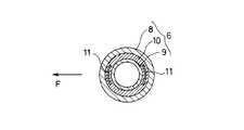
図2は、図1の自動車用車輪取付け構造に設けた防振機構の詳細を示す横方向断面図を示したものである。
【0023】
図2に示す防振機構6は、外筒8と内筒9との間に同心状に挟まれた制振材料10の中に、車両進行方向Fの前側に位置する箇所と後側に位置する箇所とに、それぞれ剛性片11,11を軸方向に延長するように挿入したものである。剛性片11は、制振材料10よりも剛性の大きいものであればよく、例えば、金属板、セラミック板、樹脂板などが使用可能である。この剛性片11の挿入により、防振機構6は車軸3に直交する前後方向への可動変位量が小さくなり、操縦安定を向上することができる。
【0024】
図3は、図1に設けた防振機構の他の例を示したものである。
【0025】
図3に示す防振機構6は、外筒8の両端部にそれぞれカギ状に内側へ折り曲げた鍔部8a,8aを形成し、他方、内筒9は中央部に径大9aを形成し、その径大部9aを外筒8の両鍔部8a,8aの間に挿入するようにしたものである。上記構成により、外筒8の鍔部8aと内筒9の径大部9aとの間が軸方向に一部対面し、そこに介在する制振材料10の厚さaが、外筒8と内筒9(径大部9a)との間の径方向の厚さbよりも小さくなるようにしている。
【0026】
このように外筒8と内筒9との間に軸方向に挟まれる制振材料7の厚さaを、径方向に挟まれる厚さbよりも小さくしたことにより、防振機構6に対して車軸3の軸方向に直交する方向(車両では上下方向)に荷重を与えたときの可動変位量δbを、同軸方向(車両では左右方向)に同一荷重を与えたときの可動変位量δaよりも大きくすることができる。この可動変位量の差(δb>δa)の設定により、実質的に操縦安定性を低下させることなく音振性能を向上することができる。
【0027】
図4は、図1に設けた防振機構のさらに他の例を示したものである。
【0028】
図4に示す防振機構6は、図3の防振機構において、内筒9の中央部に凹状の鼓形湾曲部9bを形成したものである。
【0029】
このように内筒9の中央部に鼓形湾曲部9bを形成したことにより、制振材料10の径方向(軸方向に直交する方向)の容積が図3の防振機構よりも増大し、図3の場合よりも音振性能をさらに向上することができる。
【0030】
図5は、本発明に使用する防振機構のさらに他の例を示したものである。
【0031】
この防振機構6は、制振材料10として弾性率が異なる2種類を設けたもので、外筒8の鍔8aと内筒9の径大部9aとの間に軸方向に挟まれる箇所に弾性率の大きい制振材料Aを介在させ、また外筒8と内筒9との径方向に挟まれる箇所に、制振材料Aよりも弾性率が小さい制振材料Bを介在させたものである。
【0032】
このように弾性率が互いに異なる2種類の制振材料A,B(Aの弾性率>Bの弾性率)を外筒8と内筒9との間に上記のように配置したことにより、防振機構6に対して軸方向に直交する方向(車両の上下方向)に荷重を与えたときの可動変位量δbを、同軸方向(車両の左右方向)に同一荷重を与えたときの可動変位量δaよりも大きくすることができる。したがって、実質的に操縦安定性を低下させることなく音振性能を向上することができる。
【0033】
【実施例】
外筒及び内筒をステンレス鋼にし、制振材料をゴムにした防振機構を、それぞれ図4の構造(実施例1)および図5の構造(実施例2)に異ならせて、アクスル部の車軸とハブとの間に介在させた3種類の自動車用車輪取付け構造を製作した。また、比較として、上記防振機構を介在させない自動車用車輪取付け構造を製作した。
【0034】
これら3種類の車輪取付け構造を用いて、下記の評価方法により乗心地、ロードノイズ、操縦安定性を測定したところ、表1の結果を得た。
【0035】
〔乗心地、ロードノイズ、操縦安定性〕
タイヤサイズ205/65R15 94S(リム幅6JJ)の空気入りラジアルタイヤを装着し、これを国産2.5リットルのFF車のフロントに装着したときの乗心地、ロードノイズおよび操縦安定性を、5人の訓練されたパネリストによりフィーリング・テストした。テストの評価は5点満点で採点した。
【0036】
5人のパネリストの採点のうち最大値と最低値を除外した残り三つの採点の平均値で評価を行い、その評価値を従来例を100とする指数で示した。指数が大きいほど優れていることを意味する。
【0037】
【表1】
【発明の効果】
上述したように本発明によれば、車軸とアクスルハブとの間に防振機構を介在させたことにより、この防振機構がタイヤからロードホイールのディスク部を経てアクスル部へ伝達される振動を減衰させ、音振性能の向上を可能にする。しかも、軸方向の変位は小さいため実質的に操縦安定性を低下することがなく、また防振機構は既存のロードホイールを何ら変更することなく装備できるので、低コストの製作が可能になる。
【図面の簡単な説明】
【図1】本発明の実施形態からなる自動車用車輪取付け構造の半断面図である。
【図2】図1に設けた防振機構の詳細を示す横断面図である。
【図3】図1に設けた防振機構の他の例を示す縦断面図である。
【図4】図1に設けた防振機構の更に他の例を示す縦断面図である。
【図5】図1に設けた防振機構の更に他の例を示す縦断面図である。
【符号の説明】
1 アクスル部
2 車両アクスル部
3 車軸
4 アクスルハブ
5 ベアリング
6 防振機構
8 外筒
8a 鍔部
9 内筒
9a 径大部
10 制振材料
11 剛性片[0001]
BACKGROUND OF THE INVENTION
The present invention relates to a vehicle wheel mounting structure, and more particularly, to a vehicle wheel mounting structure that improves sound vibration performance without substantially reducing steering stability.
[0002]
[Prior art]
In general, an automobile road wheel is attached to a hub of an axle connected to a vehicle body via a suspension or the like so that a disk portion thereof is fastened with bolts, nads, etc. I tried to make it compatible. However, in recent years, with the advancement of luxury in passenger cars, there has been a strong demand for further improvement in sound vibration performance such as riding comfort and road noise.
[0003]
As a countermeasure against such a request, Japanese Patent Application Laid-Open No. 6-344703 discloses spot welding between a disc portion and a rim portion separated from each other at a plurality of locations in the circumferential direction, and viscoelasticity such as asphalt or rubber on a non-welded portion. It proposes to suppress vibrations by interposing substances. However, according to this measure, it is necessary to prepare the disk part and the rim part as independent parts, so the existing wheel cannot be used, and a new mold has to be generated as a dedicated wheel. Therefore, the manufacturing cost is high and the design is limited.
[0004]
[Problems to be solved by the invention]
SUMMARY OF THE INVENTION An object of the present invention is to provide a vehicle wheel mounting structure that improves sound vibration performance without substantially reducing steering stability while leaving a conventional road wheel intact.
[0005]
[Means for Solving the Problems]
In the wheel mounting structure in which an axle hub is attached to an axle, and a road wheel is attached to the axle hub, the present invention that achieves the above object intervenes a vibration isolating mechanism between the axle and the axle hub and removes the anti-vibration mechanism. A vibration damping material is interposed between the cylinder and the inner cylinder, the outer cylinder is fixed to the hub sidebearing , and the inner cylinder is fixed to the axle side. The movable displacement amount δb when a load is applied in a direction orthogonal to the axial direction is made larger than the movable displacement amount δa when the same load is applied in the axial direction.
[0006]
In this way, an anti-vibration mechanism is interposed between the axle and the axle hub, and the anti-vibration mechanism interposes a vibration damping material between the outer cylinder and the inner cylinder, and fixes the outer cylinder to the hub-sidebearing. The inner cylinder is fixed to the axle side, and when the load is applied to the vibration isolation mechanism in the direction orthogonal to the axial direction of the axle, the same displacement is applied in the axial direction. By making it larger than the movable displacement amount δa at this time, the vibration isolation mechanism attenuates the vibration transmitted from the tire to the axle portion via the disk portion of the road wheel, thereby improving the sound vibration performance. Moreover, since the displacement in the axial direction is small, the steering stability is not substantially lowered. In addition, the anti-vibration mechanism can be installed without changing any existing road wheel, which enables low-cost production.
[0007]
DETAILED DESCRIPTION OF THE INVENTION
In the present invention, the axle portion is a structure composed of an axle and an axle hub, and a wheel (road wheel) is fixed to the axle hub. When the axle is a non-drive shaft, the axle hub is rotatably supported on the axle with a bearing inside. When the axle is a drive shaft, the axle hub is directly fixed to the drive shaft. The
[0008]
In the present invention, the vibration isolating mechanism is composed mainly of a vibration damping material. The vibration damping material is not particularly limited as long as it has a characteristic of attenuating vibration conducted from the road wheel to the axle portion. For example, rubber, thermoplastic resin, rubber is added to the thermoplastic resin. The blended thermoplastic resin elastomer composition etc. can be mentioned. Further, if necessary, the damping steel plate can be used as a damping material.
[0009]
The rubber used for the vibration damping material is not particularly limited, and may be any of synthetic rubber and natural rubber. The thermoplastic resin is not particularly limited as long as it has vibration damping characteristics.
[0010]
The thermoplastic resin elastomer composition is a composition having viscoelastic properties obtained by blending rubber with a thermoplastic resin. In particular, a thermoplastic resin having a tan δ peak in the range of 0 ° C. to 150 ° C. is used as a continuous phase, and at least a part of the continuous phase is crosslinked and a tan δ peak in the range of −100 ° C. to 0 ° C. Those in which a rubber component having a water content is dispersed are preferred. Here, the temperature showing the peak of tan δ is the temperature at which the temperature dependence curve of tan δ is obtained under the condition of 20 Hz based on JIS K7198, and the curve shows the peak.
[0011]
Examples of the rubber used in the thermoplastic resin elastomer composition include butyl rubber, olefin rubber, and natural rubber. Examples of the thermoplastic resin include polyamide resins, polypropylene resins, and polyester resins.
[0012]
The structure of the vibration isolation mechanism used in the present invention is preferably a structure in which a vibration damping material is integrally joined between the outer cylinder and the inner cylinder. Moreover, it is preferable that the damping material is integrally bonded to the outer cylinder and the inner cylinder by baking or using an adhesive. Although the above-described materials are used as the vibration damping material, metals such as steel and aluminum, fiber reinforced resin, and the like can be used for the outer cylinder and the inner cylinder.
[0013]
The vibration isolating mechanism having such a configuration is inserted so as to be interposed between the axle and the axle hub. When the axle is a drive shaft, the inner cylinder may be fixed on the axle and the outer cylinder may be fixed in the fitting hole of the axle hub. When the axle is a non-drive wheel, fixing the inner cylinder on the axle is the same as in the case of the drive wheel, but the outer cylinder is press-fitted inside a bearing mounted inside the axle hub.
[0014]
For the vibration isolation mechanism to be installed when the axle is a non-drive wheel, rigid pieces are inserted into the vibration suppression material in the vibration isolation mechanism located on the front side and the rear side, respectively, in the vehicle traveling direction.The Examples of the rigid piece include a metal plate, a ceramic plate, and a resin plate. By inserting such a rigid piece, the amount of movable displacement in the front-rear direction perpendicular to the axle of the vibration isolating mechanism is reduced, so that steering stability can be improved.
[0015]
In addition, the vibration isolation mechanism has a movable displacement amount δb when a load is applied in a direction orthogonal to the axial direction of the fastener (vertical direction in the vehicle), and the same load is applied in the axial direction (horizontal direction in the vehicle).If set to be larger than the movable displacement δa whengiven. Since the movable displacement amount δb in the direction perpendicular to the axial direction of the fastener is large as described above, the ride comfort and road noise are reduced, and the movable displacement amount δa in the axial direction of the fastener is small. It can be maintained well so as not to reduce the steering stability.
[0016]
As a means for obtaining such characteristics, for example, in the vibration damping material interposed between the outer cylinder and the inner cylinder, the thickness a of the vibration damping material sandwiched in the axial direction of the fastener is This can be achieved by making the thickness smaller than the thickness b sandwiched in the direction orthogonal to the axial direction. Further, as the damping material interposed between the outer cylinder and the inner cylinder, the elastic modulus of the damping material A sandwiched in the axial direction of the fastener and the elastic modulus of the damping material B sandwiched in the direction orthogonal to the axial direction. And the elastic modulus of the damping material A can be made larger than the elastic modulus of the damping material B.
[0017]
FIG. 1 shows an example of a vehicle wheel mounting structure according to the present invention.
[0018]
In FIG. 1, reference numeral 1 denotes an axle portion of a vehicle, and 2 denotes a road wheel equipped with a pneumatic tire (not shown).
[0019]
The axle portion 1 includes an axle 3 that is a non-drive shaft and an axle hub 4. A
[0020]
As described above, the
[0021]
In addition, since there is no change that modifies the
[0022]
Figure 2 shows atransverse cross-sectional view showing details of a vibration isolatingmechanism provided in a vehicle wheel mounting structureof FIG.
[0023]
The
[0024]
FIG. 3 showsanother example ofthe vibration isolation mechanismprovided in FIG.
[0025]
The
[0026]
In this way, the thickness a of the damping
[0027]
FIG. 4 shows still another example ofthe vibration isolation mechanismprovided in FIG.
[0028]
The
[0029]
By forming the hourglass-shaped
[0030]
FIG. 5 shows still another example of the vibration isolating mechanism used in the present invention.
[0031]
This
[0032]
By arranging two types of damping materials A and B (elastic modulus of A> elastic modulus of B) having different elastic moduli as described above between the
[0033]
【Example】
The outer tube and the inner tube and a stainless steel, an anti-vibration mechanism of the damping material and rubber, with theirrespective different for the structure ofFigure 4 structure (Example1) and 5 (Example2), the axle Three types of automobile wheel mounting structures were produced that were interposed between the axle and hub of the car. For comparison, an automobile wheel mounting structure that does not include the above-described vibration isolation mechanism was manufactured.
[0034]
Using thesethree types of wheel mounting structures, riding comfort, road noise, and steering stability were measured by the following evaluation methods, and the results shown in Table 1 were obtained.
[0035]
[Ride comfort, road noise, steering stability]
A rider equipped with a pneumatic radial tire with a tire size of 205 / 65R15 94S (rim width 6JJ), which is mounted on the front of a domestic 2.5-liter front-wheel drive vehicle. Feeling test by a trained panelist. The evaluation of the test was scored on a 5-point scale.
[0036]
The evaluation was performed using an average value of the remaining three scores excluding the maximum value and the minimum value among the scores of the five panelists. The larger the index, the better.
[0037]
[Table 1]
【The invention's effect】
As described above, according to the present invention, the vibration isolation mechanism is interposed between the axle and the axle hub, so that the vibration isolation mechanism attenuates vibration transmitted from the tire to the axle portion via the disk portion of the road wheel. And improve sound vibration performance. Moreover, since the displacement in the axial direction is small, the steering stability is not substantially lowered, and the vibration isolation mechanism can be installed without changing any existing road wheel, so that it can be manufactured at low cost.
[Brief description of the drawings]
FIG. 1 is a half sectional view of a vehicle wheel mounting structure according to an embodiment of the present invention.
FIG. 2 is a cross-sectional view showingdetails ofa vibration isolation mechanismprovided in FIG.
FIG. 3 is a longitudinal sectional view showinganother example ofthe vibration isolation mechanismprovided in FIG. 1 ;
4 is a longitudinal sectional view showing still another example ofthe vibration isolation mechanismprovided in FIG. 1. FIG.
FIG. 5 is a longitudinal sectional view showing still another example ofthe vibration isolation mechanismprovided in FIG. 1 ;
[Explanation of symbols]
DESCRIPTION OF SYMBOLS 1
Claims (6)
Translated fromJapanesePriority Applications (3)
| Application Number | Priority Date | Filing Date | Title |
|---|---|---|---|
| JP2000376402AJP4487113B2 (en) | 2000-12-11 | 2000-12-11 | Wheel mounting structure for automobiles |
| DE10160599ADE10160599A1 (en) | 2000-12-11 | 2001-12-10 | Motor vehicle wheel and associated mounting arrangement |
| US10/006,703US6565158B2 (en) | 2000-12-11 | 2001-12-10 | Automotive road wheel and attaching structure of the same |
Applications Claiming Priority (1)
| Application Number | Priority Date | Filing Date | Title |
|---|---|---|---|
| JP2000376402AJP4487113B2 (en) | 2000-12-11 | 2000-12-11 | Wheel mounting structure for automobiles |
Publications (2)
| Publication Number | Publication Date |
|---|---|
| JP2002178709A JP2002178709A (en) | 2002-06-26 |
| JP4487113B2true JP4487113B2 (en) | 2010-06-23 |
Family
ID=18845264
Family Applications (1)
| Application Number | Title | Priority Date | Filing Date |
|---|---|---|---|
| JP2000376402AExpired - Fee RelatedJP4487113B2 (en) | 2000-12-11 | 2000-12-11 | Wheel mounting structure for automobiles |
Country Status (1)
| Country | Link |
|---|---|
| JP (1) | JP4487113B2 (en) |
Families Citing this family (2)
| Publication number | Priority date | Publication date | Assignee | Title |
|---|---|---|---|---|
| JP2008121774A (en)* | 2006-11-10 | 2008-05-29 | Jtekt Corp | Rolling bearing device for wheels |
| KR20210078970A (en)* | 2019-12-19 | 2021-06-29 | 주식회사 포스코 | Surface treatment composition for vibration damping steel sheet and vibration damping steel sheet |
- 2000
- 2000-12-11JPJP2000376402Apatent/JP4487113B2/ennot_activeExpired - Fee Related
Also Published As
| Publication number | Publication date |
|---|---|
| JP2002178709A (en) | 2002-06-26 |
Similar Documents
| Publication | Publication Date | Title |
|---|---|---|
| US20120175199A1 (en) | Vehicle braking assembly with reduced squeal | |
| CN106042764B (en) | Wheel and method for manufacturing the same | |
| JP2002234304A (en) | Rim wheel with core and tire rim wheel assembly | |
| CN106985610B (en) | Airless tires and hub parts for airless tires | |
| JP3910001B2 (en) | Wheel with damper for automobile and manufacturing method thereof | |
| CN106585271B (en) | damping wheels for automobiles | |
| JP2001510418A (en) | Attenuation of wheel noise | |
| US10017202B2 (en) | Steering wheel adaptive mass dampening system | |
| JP3776722B2 (en) | Rim wheel | |
| US6565158B2 (en) | Automotive road wheel and attaching structure of the same | |
| JP4487113B2 (en) | Wheel mounting structure for automobiles | |
| JPWO2004074015A1 (en) | Tire / wheel assembly and run-flat support | |
| DE102017116430B4 (en) | WHEEL ASSEMBLY FOR A MOTOR VEHICLE | |
| JP4459085B2 (en) | Rim wheel and tire / rim wheel assembly | |
| JP4449209B2 (en) | Automotive road wheel | |
| JP2004299432A (en) | Road noise reducing device | |
| JP4386567B2 (en) | Vibration control wheel for automobile | |
| EP1247660B1 (en) | Elastic wheel | |
| JPH11245605A (en) | Rim | |
| JP2002096604A (en) | Elastic wheel | |
| JP2002205515A (en) | Pneumatic tire | |
| JP4076387B2 (en) | Tire / wheel assembly and run-flat support | |
| JP2003306014A (en) | Pneumatic tire | |
| JP2006347477A (en) | Vehicle wheel | |
| JP2002234302A (en) | Combined structure of elastic wheel and suspension member |
Legal Events
| Date | Code | Title | Description |
|---|---|---|---|
| A621 | Written request for application examination | Free format text:JAPANESE INTERMEDIATE CODE: A621 Effective date:20061110 | |
| A977 | Report on retrieval | Free format text:JAPANESE INTERMEDIATE CODE: A971007 Effective date:20081016 | |
| A131 | Notification of reasons for refusal | Free format text:JAPANESE INTERMEDIATE CODE: A131 Effective date:20081125 | |
| A521 | Written amendment | Free format text:JAPANESE INTERMEDIATE CODE: A523 Effective date:20090121 | |
| A131 | Notification of reasons for refusal | Free format text:JAPANESE INTERMEDIATE CODE: A131 Effective date:20090811 | |
| A521 | Written amendment | Free format text:JAPANESE INTERMEDIATE CODE: A523 Effective date:20090903 | |
| TRDD | Decision of grant or rejection written | ||
| A01 | Written decision to grant a patent or to grant a registration (utility model) | Free format text:JAPANESE INTERMEDIATE CODE: A01 Effective date:20100302 | |
| A01 | Written decision to grant a patent or to grant a registration (utility model) | Free format text:JAPANESE INTERMEDIATE CODE: A01 | |
| A61 | First payment of annual fees (during grant procedure) | Free format text:JAPANESE INTERMEDIATE CODE: A61 Effective date:20100315 | |
| FPAY | Renewal fee payment (event date is renewal date of database) | Free format text:PAYMENT UNTIL: 20130409 Year of fee payment:3 | |
| R150 | Certificate of patent or registration of utility model | Free format text:JAPANESE INTERMEDIATE CODE: R150 | |
| FPAY | Renewal fee payment (event date is renewal date of database) | Free format text:PAYMENT UNTIL: 20130409 Year of fee payment:3 | |
| FPAY | Renewal fee payment (event date is renewal date of database) | Free format text:PAYMENT UNTIL: 20130409 Year of fee payment:3 | |
| LAPS | Cancellation because of no payment of annual fees |