JP4485556B2 - Battery powered patient subcutaneous insertion device - Google Patents
Battery powered patient subcutaneous insertion deviceDownload PDFInfo
- Publication number
- JP4485556B2 JP4485556B2JP2007230996AJP2007230996AJP4485556B2JP 4485556 B2JP4485556 B2JP 4485556B2JP 2007230996 AJP2007230996 AJP 2007230996AJP 2007230996 AJP2007230996 AJP 2007230996AJP 4485556 B2JP4485556 B2JP 4485556B2
- Authority
- JP
- Japan
- Prior art keywords
- battery
- instrument
- circuit
- patient
- signal
- Prior art date
- Legal status (The legal status is an assumption and is not a legal conclusion. Google has not performed a legal analysis and makes no representation as to the accuracy of the status listed.)
- Expired - Lifetime
Links
Images


Classifications
- A—HUMAN NECESSITIES
- A61—MEDICAL OR VETERINARY SCIENCE; HYGIENE
- A61B—DIAGNOSIS; SURGERY; IDENTIFICATION
- A61B5/00—Measuring for diagnostic purposes; Identification of persons
- A61B5/0002—Remote monitoring of patients using telemetry, e.g. transmission of vital signals via a communication network
- A61B5/0031—Implanted circuitry
- A—HUMAN NECESSITIES
- A61—MEDICAL OR VETERINARY SCIENCE; HYGIENE
- A61B—DIAGNOSIS; SURGERY; IDENTIFICATION
- A61B5/00—Measuring for diagnostic purposes; Identification of persons
- A61B5/07—Endoradiosondes
- A—HUMAN NECESSITIES
- A61—MEDICAL OR VETERINARY SCIENCE; HYGIENE
- A61N—ELECTROTHERAPY; MAGNETOTHERAPY; RADIATION THERAPY; ULTRASOUND THERAPY
- A61N1/00—Electrotherapy; Circuits therefor
- A61N1/18—Applying electric currents by contact electrodes
- A61N1/32—Applying electric currents by contact electrodes alternating or intermittent currents
- A61N1/36—Applying electric currents by contact electrodes alternating or intermittent currents for stimulation
- A61N1/372—Arrangements in connection with the implantation of stimulators
- A61N1/378—Electrical supply
- A61N1/3787—Electrical supply from an external energy source
- A—HUMAN NECESSITIES
- A61—MEDICAL OR VETERINARY SCIENCE; HYGIENE
- A61B—DIAGNOSIS; SURGERY; IDENTIFICATION
- A61B2560/00—Constructional details of operational features of apparatus; Accessories for medical measuring apparatus
- A61B2560/02—Operational features
- A61B2560/0204—Operational features of power management
- A61B2560/0214—Operational features of power management of power generation or supply
- A61B2560/0219—Operational features of power management of power generation or supply of externally powered implanted units
- A—HUMAN NECESSITIES
- A61—MEDICAL OR VETERINARY SCIENCE; HYGIENE
- A61B—DIAGNOSIS; SURGERY; IDENTIFICATION
- A61B2560/00—Constructional details of operational features of apparatus; Accessories for medical measuring apparatus
- A61B2560/06—Accessories for medical measuring apparatus
- A61B2560/063—Devices specially adapted for delivering implantable medical measuring apparatus
- A—HUMAN NECESSITIES
- A61—MEDICAL OR VETERINARY SCIENCE; HYGIENE
- A61B—DIAGNOSIS; SURGERY; IDENTIFICATION
- A61B2562/00—Details of sensors; Constructional details of sensor housings or probes; Accessories for sensors
- A61B2562/08—Sensors provided with means for identification, e.g. barcodes or memory chips
- A—HUMAN NECESSITIES
- A61—MEDICAL OR VETERINARY SCIENCE; HYGIENE
- A61B—DIAGNOSIS; SURGERY; IDENTIFICATION
- A61B5/00—Measuring for diagnostic purposes; Identification of persons
- A61B5/05—Detecting, measuring or recording for diagnosis by means of electric currents or magnetic fields; Measuring using microwaves or radio waves
- A61B5/053—Measuring electrical impedance or conductance of a portion of the body
- A—HUMAN NECESSITIES
- A61—MEDICAL OR VETERINARY SCIENCE; HYGIENE
- A61B—DIAGNOSIS; SURGERY; IDENTIFICATION
- A61B5/00—Measuring for diagnostic purposes; Identification of persons
- A61B5/145—Measuring characteristics of blood in vivo, e.g. gas concentration or pH-value ; Measuring characteristics of body fluids or tissues, e.g. interstitial fluid or cerebral tissue
- A61B5/14532—Measuring characteristics of blood in vivo, e.g. gas concentration or pH-value ; Measuring characteristics of body fluids or tissues, e.g. interstitial fluid or cerebral tissue for measuring glucose, e.g. by tissue impedance measurement
- A—HUMAN NECESSITIES
- A61—MEDICAL OR VETERINARY SCIENCE; HYGIENE
- A61B—DIAGNOSIS; SURGERY; IDENTIFICATION
- A61B5/00—Measuring for diagnostic purposes; Identification of persons
- A61B5/45—For evaluating or diagnosing the musculoskeletal system or teeth
- A61B5/4519—Muscles
- A—HUMAN NECESSITIES
- A61—MEDICAL OR VETERINARY SCIENCE; HYGIENE
- A61F—FILTERS IMPLANTABLE INTO BLOOD VESSELS; PROSTHESES; DEVICES PROVIDING PATENCY TO, OR PREVENTING COLLAPSING OF, TUBULAR STRUCTURES OF THE BODY, e.g. STENTS; ORTHOPAEDIC, NURSING OR CONTRACEPTIVE DEVICES; FOMENTATION; TREATMENT OR PROTECTION OF EYES OR EARS; BANDAGES, DRESSINGS OR ABSORBENT PADS; FIRST-AID KITS
- A61F2/00—Filters implantable into blood vessels; Prostheses, i.e. artificial substitutes or replacements for parts of the body; Appliances for connecting them with the body; Devices providing patency to, or preventing collapsing of, tubular structures of the body, e.g. stents
- A61F2/50—Prostheses not implantable in the body
- A61F2/68—Operating or control means
- A61F2/70—Operating or control means electrical
- A61F2/72—Bioelectric control, e.g. myoelectric
- A—HUMAN NECESSITIES
- A61—MEDICAL OR VETERINARY SCIENCE; HYGIENE
- A61F—FILTERS IMPLANTABLE INTO BLOOD VESSELS; PROSTHESES; DEVICES PROVIDING PATENCY TO, OR PREVENTING COLLAPSING OF, TUBULAR STRUCTURES OF THE BODY, e.g. STENTS; ORTHOPAEDIC, NURSING OR CONTRACEPTIVE DEVICES; FOMENTATION; TREATMENT OR PROTECTION OF EYES OR EARS; BANDAGES, DRESSINGS OR ABSORBENT PADS; FIRST-AID KITS
- A61F2/00—Filters implantable into blood vessels; Prostheses, i.e. artificial substitutes or replacements for parts of the body; Appliances for connecting them with the body; Devices providing patency to, or preventing collapsing of, tubular structures of the body, e.g. stents
- A61F2/50—Prostheses not implantable in the body
- A61F2002/5058—Prostheses not implantable in the body having means for restoring the perception of senses
- A—HUMAN NECESSITIES
- A61—MEDICAL OR VETERINARY SCIENCE; HYGIENE
- A61F—FILTERS IMPLANTABLE INTO BLOOD VESSELS; PROSTHESES; DEVICES PROVIDING PATENCY TO, OR PREVENTING COLLAPSING OF, TUBULAR STRUCTURES OF THE BODY, e.g. STENTS; ORTHOPAEDIC, NURSING OR CONTRACEPTIVE DEVICES; FOMENTATION; TREATMENT OR PROTECTION OF EYES OR EARS; BANDAGES, DRESSINGS OR ABSORBENT PADS; FIRST-AID KITS
- A61F2/00—Filters implantable into blood vessels; Prostheses, i.e. artificial substitutes or replacements for parts of the body; Appliances for connecting them with the body; Devices providing patency to, or preventing collapsing of, tubular structures of the body, e.g. stents
- A61F2/50—Prostheses not implantable in the body
- A61F2/68—Operating or control means
- A61F2/70—Operating or control means electrical
- A61F2002/704—Operating or control means electrical computer-controlled, e.g. robotic control
- A—HUMAN NECESSITIES
- A61—MEDICAL OR VETERINARY SCIENCE; HYGIENE
- A61F—FILTERS IMPLANTABLE INTO BLOOD VESSELS; PROSTHESES; DEVICES PROVIDING PATENCY TO, OR PREVENTING COLLAPSING OF, TUBULAR STRUCTURES OF THE BODY, e.g. STENTS; ORTHOPAEDIC, NURSING OR CONTRACEPTIVE DEVICES; FOMENTATION; TREATMENT OR PROTECTION OF EYES OR EARS; BANDAGES, DRESSINGS OR ABSORBENT PADS; FIRST-AID KITS
- A61F2/00—Filters implantable into blood vessels; Prostheses, i.e. artificial substitutes or replacements for parts of the body; Appliances for connecting them with the body; Devices providing patency to, or preventing collapsing of, tubular structures of the body, e.g. stents
- A61F2/50—Prostheses not implantable in the body
- A61F2/68—Operating or control means
- A61F2/70—Operating or control means electrical
- A61F2002/705—Electromagnetic data transfer
- A—HUMAN NECESSITIES
- A61—MEDICAL OR VETERINARY SCIENCE; HYGIENE
- A61N—ELECTROTHERAPY; MAGNETOTHERAPY; RADIATION THERAPY; ULTRASOUND THERAPY
- A61N1/00—Electrotherapy; Circuits therefor
- A61N1/18—Applying electric currents by contact electrodes
- A61N1/32—Applying electric currents by contact electrodes alternating or intermittent currents
- A61N1/36—Applying electric currents by contact electrodes alternating or intermittent currents for stimulation
- A61N1/372—Arrangements in connection with the implantation of stimulators
- A61N1/37205—Microstimulators, e.g. implantable through a cannula
Landscapes
- Health & Medical Sciences (AREA)
- Life Sciences & Earth Sciences (AREA)
- Engineering & Computer Science (AREA)
- Animal Behavior & Ethology (AREA)
- General Health & Medical Sciences (AREA)
- Veterinary Medicine (AREA)
- Public Health (AREA)
- Biomedical Technology (AREA)
- Heart & Thoracic Surgery (AREA)
- Medical Informatics (AREA)
- Molecular Biology (AREA)
- Surgery (AREA)
- Physics & Mathematics (AREA)
- Pathology (AREA)
- Biophysics (AREA)
- Computer Networks & Wireless Communication (AREA)
- Nuclear Medicine, Radiotherapy & Molecular Imaging (AREA)
- Radiology & Medical Imaging (AREA)
- Electrotherapy Devices (AREA)
Description
Translated fromJapanese本発明は患者の皮下に挿入するように構成された器具に関し、特に例えば神経または筋肉のような組織の刺激、および/またはパラメタの監視、および/またはデータ通信を含む種々の目的のために電子回路に給電するためのバッテリを内蔵した上記の器具に関する。 The present invention relates to an instrument configured for insertion under the skin of a patient, and in particular electronic for various purposes including stimulation of tissues such as nerves or muscles, and / or parameter monitoring and / or data communication. The present invention relates to the above-mentioned instrument having a battery for supplying power to the circuit.
組織の刺激のための皮下挿入器具(すなわちマイクロスティミュレータ)はこの分野では公知である。例えば本明細書に参考文献として引用されている米国特許明細書第5,193,539号;5,193,540号;5,312,439号;5,324,316号;5,358,514号;5,405,367号;5,571,148号を参照されたい。 Subcutaneous insertion instruments (ie, microstimulators) for tissue stimulation are known in the art. For example, US Pat. Nos. 5,193,539; 5,193,540; 5,312,439; 5,324,316; 5,358,514, cited herein as references. No. 5,405,367; 5,571,148.
このような公知のマイクロスティミュレータは、間隔を隔てた電極の間に僅かな電流を発生する電子回路を収納した密閉されたハウジングを特徴としている。目標の組織の近傍にマイクロスティミュレータを精密に挿入することによって、電流が神経を刺激して、医学的に有益な結果が得られる。 Such known microstimulators feature a hermetically sealed housing that houses an electronic circuit that generates a small current between spaced electrodes. By precisely inserting a microstimulator in the vicinity of the target tissue, the current stimulates the nerve and produces a medically beneficial result.
標準的には、このような従来形のマイクロスティミュレータは例えばマイクロスティミュレータの近傍に実装された励振コイルによって発生される外部のAC磁界と誘導的に結合された内部コイルから動作電力を誘導する。内部コイル内に誘導されたAC電圧は整流され、かつ濾波されて、DC動作電圧が生成され、これが電子回路の給電に利用される。このような構成では、組織の刺激を維持するために、ユーザーが励振コイルに密着して留まっている必要がある。 Typically, such conventional microstimulators derive operating power from an internal coil that is inductively coupled to an external AC magnetic field generated, for example, by an excitation coil mounted in the vicinity of the microstimulator. . The AC voltage induced in the internal coil is rectified and filtered to produce a DC operating voltage that is used to power the electronic circuit. Such a configuration requires the user to remain in close contact with the excitation coil in order to maintain tissue stimulation.
本発明は例えば神経または筋肉のような組織の刺激、および/またはパラメタの監視、および/またはデータ通信の目的のために患者の皮膚の下に挿入するように構成された器具に関する。本発明に基づく器具は、好適には軸方向の寸法が60mm未満、横方向の寸法が6mm未満で、入力/出力トランスデューサを起動するために電力消費回路に少なくとも1マイクロワット時を供給できる自蔵式電源を含む密閉されたハウジングからなっている。各々の器具の回路は好適には遠隔操作でアドレス可能であり、データ信号受信機と器具コントローラとを含んでいる。 The present invention relates to an instrument configured to be inserted under a patient's skin for purposes of stimulating tissue and / or parameters such as nerves or muscles, and / or data communication. The instrument according to the invention is self-contained, preferably having an axial dimension of less than 60 mm and a lateral dimension of less than 6 mm and capable of supplying at least 1 microwatt hour to the power consuming circuit to activate the input / output transducer. It consists of a sealed housing containing a power supply. Each instrument circuit is preferably remotely addressable and includes a data signal receiver and an instrument controller.
器具の使用意図に応じて、電力消費回路を例えば嚢状組織の刺激のために比較的短期間だけ高負荷電流を要求するように、または例えば骨の成長刺激のために大幅に長い期間、または継続的に低負荷電流を要求するように設計することができる。本発明に基づいて、本発明に基づく電源は、標準的な用途で1時間以上に亘って回路に給電でき、ひいてはユーザーが外部の磁界発生器と継続的に結合されなくても済むように、少なくとも1マイクロワット時の容量を有している。 Depending on the intended use of the device, the power consuming circuit may require a high load current for a relatively short period, for example for sac irritation, or a significantly longer period, for example for bone growth stimulation, or It can be designed to require low load current continuously. In accordance with the present invention, the power supply according to the present invention can power the circuit for more than an hour in standard applications, thus eliminating the need for the user to be continuously coupled to an external magnetic field generator. It has a capacity of at least 1 microwatt hour.
本発明の重要な側面に基づいて、電源は好適には間に電解質を含む一対の導電板によって形成されたバッテリからなっている。バッテリは好適には渦電流の形成が最小限になるように物理的に構成されている。 In accordance with an important aspect of the present invention, the power source preferably comprises a battery formed by a pair of conductive plates with an electrolyte therebetween. The battery is preferably physically configured to minimize eddy current formation.
本発明の好適に実施例に基づき、バッテリを再充電するための充電回路が備えられている。充電回路は外部で発生されるAC磁界に応動して充電電流を発生可能である。
本発明の更に別の側面では、外部充電器を使用して前述の充電回路にエネルギを供給するためのAC磁界が周期的に発生され、好適な1実施例はバッテリの状態を表す外部充電器へのデータ信号を発生する手段を含んでいる。In accordance with a preferred embodiment of the present invention, a charging circuit for recharging the battery is provided. The charging circuit can generate a charging current in response to an AC magnetic field generated outside.
In yet another aspect of the invention, an AC magnetic field is generated periodically to supply energy to the aforementioned charging circuit using an external charger, and one preferred embodiment is an external charger that represents the state of the battery. Means for generating a data signal to the.
本発明の更に別の側面では、システムで使用される各々の皮下挿入器具内に識別アドレスが記憶されていることで、個々の器具のアドレス指定が可能である。すなわち、各器具内のデータ信号受信機はその器具に記憶されているアドレスを識別するデータ信号に応答して、器具の入力/出力トランスデューサを起動する。 In yet another aspect of the invention, an identification address is stored in each subcutaneous insertion instrument used in the system, allowing individual instrument addressing. That is, the data signal receiver within each instrument activates the instrument's input / output transducers in response to the data signal identifying the address stored in that instrument.
本発明に基づく入力/出力トランスデューサは好適には少なくとも1つの電極を備えている。神経の刺激用に使用される場合、コントローラは電極に一連の励振パルスを供給して、隣接する神経を刺激する。パラメタ監視用に使用される場合は、電極はある身体状態を示す電気信号を監視するために利用される。 The input / output transducer according to the invention preferably comprises at least one electrode. When used for nerve stimulation, the controller provides a series of excitation pulses to the electrodes to stimulate adjacent nerves. When used for parameter monitoring, the electrodes are used to monitor electrical signals indicative of certain physical conditions.
本発明の好適な実施例の重要な特徴に基づき、皮下挿入可能な各々の器具は下記の動作モードの1つ、またはそれ以上で選択的に動作するように個々にアドレス指定、およびプログラムされることができる。すなわち、(1)刺激、(2)監視、および/または(3)通信である。 In accordance with important features of the preferred embodiment of the present invention, each subcutaneously insertable instrument is individually addressed and programmed to selectively operate in one or more of the following modes of operation: be able to. That is, (1) stimulation, (2) monitoring, and / or (3) communication.
本発明の新規な特徴は特に添付の請求の範囲に記載されている。本発明は添付図面を参照した以下の説明から最も明解に理解されよう。 The novel features of the invention are set forth with particularity in the appended claims. The invention will be best understood from the following description with reference to the accompanying drawings.
本発明は例えば神経または筋肉のような組織の刺激、および/またはパラメタの監視、および/またはデータ通信の目的のために患者の皮下に挿入するように構成された器具に関する。本発明に基づく器具は、好適には軸方向の寸法が60mm未満、横方向の寸法が6mm未満で、電源と、コントローラ、アドレス記憶手段、データ信号受信器、および入力/出力トランスデューサを含む電力消費回路とを含む密閉されたハウジングからなっている。スティミュレータとして使用する場合は、このような器具は例えば苦痛を軽減、または除去し、身体機能を良好にするために特定の筋肉または器官を刺激する(例えば衰弱した、または未調整の筋肉を鍛練するため、または尿失禁を抑制するため))等の神経および関連する神経経路を刺激するための多様な用例で有用である。本発明のマイクロスティミュレータは好適には磁気、無線周波数(RF)または超音波信号を介した制御目的のために個々にアドレス指定可能である。 The present invention relates to instruments configured to be inserted subcutaneously into a patient for purposes of stimulation of tissue, such as nerves or muscles, and / or parameter monitoring, and / or data communication. The instrument according to the present invention preferably has an axial dimension of less than 60 mm and a lateral dimension of less than 6 mm and includes a power source and a controller, address storage means, data signal receiver, and input / output transducer. And a sealed housing containing a circuit. When used as a stimulator, such instruments can stimulate specific muscles or organs (eg, train weakened or unconditioned muscles) to reduce or eliminate pain and improve physical function, for example. Useful in a variety of applications for stimulating nerves and related neural pathways, such as to suppress urinary incontinence)). The microstimulators of the present invention are preferably individually addressable for control purposes via magnetic, radio frequency (RF) or ultrasonic signals.
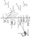
図1は送信機20によって付勢される外部に実装されたコイル19によって発生される交番磁界を介して外部の電源14からの電力を受ける、患者の皮膚12の下に挿入される(前述の米国特許明細書第5,312,439号の図1に示すような)従来形の皮下挿入スティミュレータ10の実施例を示している。スティミュレータ10内では、磁界がコイル22内でAC電流を発生し、これは整流器24によって整流され、かつ調整器28と組み合わせてコンデンサ26内に蓄電されて、論理回路30に給電する電圧を発生する。次に論理回路30を利用して電極32と34の間に刺激電流が発生される。制御論理30は動作電力の供給にはコンデンサ26内に蓄積された電力に依存するので、標準的には外部電源14が除去された後の短期間で、コンデンサ26内に蓄積された電荷が減損するので、論理回路は機能を停止する。その結果、例えば神経経路の痛みを抑制するために継続的な刺激が必要な用例でこのようなスティミュレータ10を使用する場合、外部電源14が継続的に存在し、起動される必要がある。このように継続的に外部電源を備えることは携帯式電源を使用することによって達成できるものの、それが物理的に存在することでライフスタイルに制約が生ずるものと考えられる。 FIG. 1 is inserted underneath a patient's
これに対して、図2は外部電源を継続的に使用する必要なく、より長い期間、すなわち1時間以上も組織(例えば神経経路または神経)を刺激できる(マイクロスティミュレータとして構成された)本発明の給電式皮下挿入器具100のブロック図を示している。その結果、ある実施例では好適なマイクロスティミュレータ100を使用して外部電源を取り外したかなり後でも、より長い期間に亘って選択された神経の痛みを抑止することができる。本発明のマイクロスティミュレータ100は例えば再充電可能なバッテリ104のような電源102を密閉するための密閉ハウジング206(図5を参照)、および(1)電源102によって給電され、かつ識別アドレス(ID)が記憶されたアドレス記憶回路108を有するコントローラ回路106と、(2)電源102によって給電され、かつコントローラ回路106の制御下で動作して、1つ、またはそれ以上の電極(すなわちトランスデューサ)112に励振パルスを供給するための刺激回路110と、(3)指令およびアドレス識別情報をコントローラ回路106に供給するための受信機114とを含む電力消費回路とを備えてなっている。 In contrast, FIG. 2 illustrates the present invention (configured as a microstimulator) that can stimulate tissue (eg, a nerve pathway or nerve) for a longer period of time, ie, more than one hour, without the need to continuously use an external power source The block diagram of the electric power feeding type
好適な実施例では、電源102は充電回路と組合わせて使用され、コントローラ回路106と刺激回路110とをより長期間起動させるのに充分な電力を供給するための再充電可能なバッテリ104からなっている。しかし、あるいは本発明の実施例は、養生処置が比較的短期間であり、ひいては電力需要が主バッテリの電力容量内にあるような用例では、再充電可能なバッテリ104の代わりに主バッテリを使用してもよい。
動作時には、コイル116は外部電源118(図3Aを参照)から発生される交番磁界の形式の電力を受け、それに応動してAC電流を整流器120に供給し、この電流は整流されたDC電流として充電回路122に送られる。次に充電回路122はバッテリ104上の電圧Vを監視し、好適な充電特性(電流および電圧)に基づいてバッテリを充電する。後により詳細に説明するように、充電回路122は好適には経路124を経てコントローラ回路106と通信し、一方、このコントローラ回路は磁気、超音波またはRF信号を介して外部電源118と周期的に通信する。In the preferred embodiment, the power supply 102 is used in combination with a charging circuit and comprises a
In operation, the
標準的な用例(図3Aを参照)では、例えばマイクロスティミュレータのような複数個のこのような器具100が患者の身体の皮膚12の下に挿入され、同時に外部電源118からの交番磁界154にさらされる。従って、充電回路122によってバッテリ104が充分に充電されたことが一旦判定されると、充電回路122は好適には例えばセンタタップ126を分路させ(またはコイルにコンデンサを追加することによって)コイル116を離調させ、ひいては過充電による充電回路122またはバッテリ104内での熱の発生を最小限にする。このように、外部電源118は交番磁界を介して無限に充電電力を供給し続けることができる。しかし、好適な1実施例では、外部電源は挿入された器具の状態に関する情報を周期的にポーリングし、各々の皮下挿入された器具100からそのバッテリ104が充電されたという状態情報を受けるまで電力の充電を継続する。 In a standard application (see FIG. 3A), a plurality of
コントローラ回路106(電力入力端子127aを介して)と、刺激回路110(電力入力端子127bを介して)の双方とも、バッテリ104の出力端子128から電力を受ける。皮下挿入された器具100内の回路の電力散逸はCMOSおよびその他のより低電力の論理回路を使用することによって最小限に抑止される。従って、バッテリ104の必要な容量は最小限で済む。Both controller circuit 106 (via power input terminal 127 a) and stimulation circuit 110 (via power input terminal 127 b) receive power from
コントローラ回路106は、コントローラ130と結合されたコンフィギュレーション・データ記憶装置132内のコンフィギュレーション・データに従って、(好適には状態機械またはマイクロプロセッサである)コントローラ130を使用して刺激回路110の動作を制御する。コンフィギュレーション・データはコントローラ130によって制御される刺激回路110によって発生される励振パルスの特性に作用を及ぼす様々なプログラム可能なパラメタ(これについては後述する)を特定する。好適には、各々の皮下挿入器具100、例えばマイクロスティミュレータは外部の単数または複数個の装置との通信を介して起動(使用可能/使用不能)にすることができ、またはその特性を変更することができる。従って、各々の皮下挿入器具100は例えばEEPROM、PROMまたは製造中にプログラムされたその他の不揮発性記憶装置のようなアドレス記憶装置108を使用して、(例えば8ビットまたはそれ以上のビット内で記憶されたIDコードを用いて)それ自体を特定する。あるいは、アドレス記憶装置108はマスク・プログラムされてIDの全て、または一部が形成された集積回路の一部からなっていてもよく、および/またはIDの全て、または残りの一部を指定するレーザー・トリミング・プロセスを利用してもよい。更に別の実施例では、IDは個別に、またはレーザー・トリミング・プロセスと組合わせて使用される例えばワイヤボンドのようなジャンパの選択によって指定することもできる。動作時には、(例えば充電器118のような)外部装置はアドレス欄を含む指令情報を含んだ変調された磁気、超音波またはRF指令信号を発信する。皮下挿入器具100がこの指令信号を受信し、復調して内部の指令情報を受けると、皮下挿入器具は先ず、そのデータの残りを処理する前にそのアドレス記憶装置108内のアドレスと整合するか否かを判定する。否である場合は、指令信号は無視される。 The
第1実施例では、交番磁界154はこの指令信号によって振幅変調される。受信機回路114aは(好適には再充電可能なバッテリ104を充電するために使用されるものと同じコイルである)コイル116の間で発生された信号を監視することによって、この指令信号を検出し、かつ復調する。復調されたデータは経路136を介してコントローラのデータ入力134に送られ、そこで特定の皮下挿入器具100への使用可能性が判定される。あるいは、指令信号がRF信号を変調し、これがアンテナとしてコイル116を利用して、または別個のアンテナを使用して(RF信号を復調するように構成された)受信機114aによって同様に検出されるようにしてもよい。In the first embodiment, the alternating magnetic field 154 is amplitude-modulated by this command signal. The receiver circuit 114a by monitoring the (preferably the same coil asthose used to charge the rechargeable battery 104) the signals generated between the
次に実施例では、超音波信号を利用して各々の皮下挿入器具100に上記の指令信号を送ることができる。この実施例では、器具100内に配置された超音波トランスデューサ138が信号140を発生し、これが超音波復調器114bによって復調される。復調されたこの信号は次に経路144を経て超音波データ入力142に送られ、磁気信号に関して前述したと同様に処理される。超音波を利用した実施例には、患者の身体が主として超音波信号を導通させる液体と組織からなっているという点で重要な利点がある。その結果、患者の身体の内部のいずれかに設置された(または外部ではあるが身体と接触している)制御装置は内部に挿入された各々の器具100と通信することができる。 Next, in the embodiment, the command signal can be sent to each of the
好適な実施例では、皮下挿入器具100は状態とデータとを外部装置に発信する手段を含んでいる。充電モードの例では、各々の器具100が充電器118と個別的に通信でき、その結果、皮下挿入された器具100の全てが完全に充電された場合に、充電器118がその旨を判定できることが好適である。好適には、器具100は前記のデータによって変調された磁気信号を発信する送信機を含んでいる。この送信機はAC電圧を振幅変調し、かつこの変調された信号を、変調された磁気信号を発するコイル116に送る変調器回路147からなっている。変調されたこの信号は充電器118によって利用されるAC信号の搬送波周波数とは異なる周波数を用いることができるものの、通信チャネル、すなわち器具間の磁界154は図3Bに示したように時分割されていることが好適である。図3Bでは、充電器118は第1の期間148に交番磁界を発する。第1の期間148の終了時に、この交番磁界は選択されたマイクロスティミュレータ100に対応する(すなわち1つの皮下挿入器具のアドレスを含む)ポーリング・データに対応する一連のビットで変調(例えば振幅変調)される。次に充電器118は第2の期間150の間に受信モードに入り、その期間中に選択された器具100はそのバッテリ状態に対応する一連のビットで変調された磁気信号を発する。この充電/ポーリング周期は好適には充電器118の動作範囲内の全ての皮下挿入器具について反復される。器具100の全てが充電されたことを充電器118が判定すると、周期は終了し、好適には例えば視覚的または音響報知器152を利用して患者または医師にその旨が報知される。In the preferred embodiment, the
あるいは、超音波手段を利用して皮下挿入器具100から外部装置に状態またはその他のデータを通信することができる。このような実施例では、コントローラ130の制御下で超音波発信器168が線170上で変調信号を発生し、これが超音波トランスデューサ138によって発信される。前述したように、超音波信号は身体内の液体および組織を効率よく導通するので、これは例えば別のマイクロスティミュレータ100のような患者の身体内に挿入された器具間での通信のための好適な通信手段であり、患者の皮膚と接触する外部装置との通信にも適している。 Alternatively, status or other data can be communicated from the
磁気通信または超音波通信手段、すなわち送信機と受信機の使用は互いに排他的なものではなく、実際に好適な皮下挿入器具は双方を含んでいる。図3Aに示した例の場合は、医師のプログラマ172(主として皮下挿入器具100の動作をプログラムする装置)は磁気エミッタ190からの変調された磁気信号を使用してマイクロスティミュレータ100aと通信し、かつそのバッテリ状態を反映する変調磁気信号をマイクロスティミュレータ100aから周期的に受信することができる。このような磁気通信手段は充電モード中は好適であるものの、患者制御ユニット174(例えば代表的には主として埋設された器具100の状態を監視するために使用される“腕時計”の形状の、皮膚と直に接触する装置)は超音波手段を利用した方が好適に通信する。加えて、皮下注入されたマイクロスティミュレータ100の相互間の通信も、例えば主従、またはトランスポンダ従機構造では望ましい。このようなモードでは、超音波信号は身体内の液体を効率よく通過するので超音波手段が好適である。 The use of magnetic or ultrasonic communication means, i.e. transmitters and receivers, is not mutually exclusive and practically suitable subcutaneous insertion instruments include both. In the example shown in FIG. 3A, a physician's programmer 172 (primarily a device that programs the operation of the subcutaneous insertion instrument 100) communicates with the microstimulator 100a using the modulated magnetic signal from the
本発明のバッテリ充電式器具100は好適には例えば通信された指令信号を介して複数の動作モードで動作するように構成することができる。あるいは、事前組立てされたバッテリ給電式の皮下挿入器具も本発明の範囲内にあるものとみなされる。第1の動作モードでは、(皮下注射針の形式の挿入器具176を使用して挿入可能なサイズの)器具100はマイクロスティミュレータ(例えば100aおよび100b)に適しているので、スティミレータとして構成される。この実施例では、コントローラ130は刺激回路110に対して電極112を通る励振パルス列を発生して、マイクロスティミュレータ100aまたは100bの挿入位置の近傍の例えば神経のような組織を刺激する。動作時には、プログラム可能なパルス発生機178および電圧増倍器180が所望のパルス列に対応し、かつ(例えば充電されたコンデンサまたは同様に充電されたバッテリ部分を加算することによって)バッテリ電圧をどの程度増倍させるかを指定するパラメタ(表1を参照)と共に成されている。第1FET182は周期的に付勢され、コンデンサ183に電荷を(身体組織を通る低電流の導通速度で第1の方向に)蓄積し、かつ第2FET184は周期的に付勢されて、近傍の神経を刺激するようにより高い電流の導通速度で反対方向にコンデンサ183を放電する。あるいは、前述の参照文献に記載されているように、身体組織内で等価のコンデンサを形成するような電極を選択することもできる。 The
電流:蓄電コンデンサの連続的な充電
充電電流:1、3、10、30、100、250、500μa
電流範囲:公称3.2%段階で0.8から40ma
コンプライアンス電圧:3ボルト段階で3−24ボルトまで選択可能
パルス周波数(PPS):公称30%段階で1から500PPSまで
パルス幅:公称10%段階で5から2000μSまで
バースト・オン時間(BON):公称20%段階で1msから24時間まで
バースト・オフ時間(BOF):公称20%段階で1msから24時間まで
BONまでのトリガ遅延:選択されたBOFまたはパルス幅
バースト反復期間:公称20%段階で1msから24時間まで
ランプ・オン時間:0.1から100秒(1、2、5、10段階)
ランプ・オフ時間:0.1から100秒(1、2、5、10段階)
表1−刺激パラメタ
Current: Continuous charging and charging current of the storage capacitor: 1, 3, 10, 30, 100, 250, 500 μa
Current range: 0.8 to 40ma at nominal 3.2% level
Compliance voltage: selectable from 3 to 24 volts in 3 volts step Pulse frequency (PPS): 1 to 500 PPS in nominal 30% step Pulse width: Burst on time (BON) in nominal 10% step from 5 to 2000 μS: nominal Burst off time (BOF) from 1 ms to 24 hours in 20% phase: Trigger delay from 1 ms to 24 hours in nominal 20% phase: selected BOF or pulse width burst repetition period: 1 ms in nominal 20% phase Lamp on time from 1 to 24 hours: 0.1 to 100 seconds (1, 2, 5, 10 steps)
Lamp off time: 0.1 to 100 seconds (1, 2, 5, 10 steps)
Table 1-Stimulus parameters
これまでより長期間に亘って組織を刺激することが望ましいことを記載してきたが、故障モードも考えられる。従って、好適には磁気センサ186(好適には例えばホール効果センサのような半導体)がコントローラ130に結合され、これは静磁界にさらされた場合にマイクロスティミュレータ100の機能を修正するために、たとえば動作の中断するために利用できる。このような磁気センサ186はマイクロスティミュレータ100の近傍の患者の皮膚12に(静磁界を発生するために)安全磁石187を配置することによって起動することができる。加えて、そのバッテリ電圧がその下限に達し、それが充電回路122によって判定され、コントローラ回路106に通信された場合(または最高温度に達した場合)、マイクロスティミュレータ100が動作を停止することが望ましい。それによって再充電可能なバッテリ104の信頼できる動作と、有効寿命の延長が保証される。この低電圧状態が検出されると、好適な器具は(好適には遠隔位置で発生される呼掛け/ポーリング信号に応答して)周期的に対応する状態信号を発してバッテリの再充電を要求する。 While it has been described that it is desirable to stimulate tissue for a longer period of time, failure modes are also contemplated. Thus, preferably a magnetic sensor 186 (preferably a semiconductor such as a Hall effect sensor) is coupled to the controller 130, which modifies the function of the
次の動作モードでは、バッテリ給電式の皮下挿入器具100は皮下挿入された器具の環境で1つ、またはそれ以上の生理学的または生物学的なパラメタを検出可能であるセンサ、すなわちマイクロセンサ100cとして動作するように構成することができる。好適な動作モードでは、例えば外部に設置された機器または皮下挿入器具であるシステム・コントローラはアドレス記憶装置108内に記憶されたIDを利用して各々のマイクロセンサ100Cから検出されたデータを周期的に要求し、かつそれに応答して、検出されたデータに従って調整されたマイクロスティミュレータ、例えば100aおよび100bに指令信号を送信する。例えば、センサ188を電極112に結合して、温度、グルコースまたはO2含料のような生物学的なパラメタを測定するために検出、またはその他の方法で使用することができる。あるいは、超音波トランスデューサ138またはコイル116を使用して、一対の皮下挿入器具の間で伝送される信号の磁気、または超音波信号の大きさ(または走行継続期間)をそれぞれ測定し、それによってこれらの器具の相対位置を判定することもできる。この情報は例えば肘または指の曲がった程度のような身体運動の料を判定するために利用でき、ひいては閉ループ運動制御システムの一部を構成することができる。In the next mode of operation, the battery-powered
別の動作モードでは、バッテリ給電式皮下挿入器具100はトランスポンダ、すなわちマイクロ・トランスポンダ100dとして動作するように構成することができる。この動作モードでは、マイクロ・トランスポンダは(例えば磁気または超音波の前述の受信手段を介して)システム・コントトローラから第1指令信号を受信し、この信号を(好適には再様式化した後で)、(例えば磁気または超音波の)前述の送信手段を使用して他の皮下挿入器具)(例えばマイクロスティミュレータ、マイクロ送信機、および/またはマイクロ・トランスポンダ)に再送信する。マイクロ・トランスポンダは例えば磁気のような1つの態様の指令信号を受信できるが、例えば超音波のような別の態様で信号を再送信することもできる。例えば、医師のプログラマ172は磁気エミッタ190を使用して皮下挿入器具をプログラム/指令するために変調された磁気信号を発してもよい。しかし、発信された信号の大きさは全ての皮下挿入器具によって良好に受信されるには不十分であることがある。従って、マイクロスティミュレータ100dが変調された磁気信号を受信し、かつこれを(好適には再様式化の後で)より少ない制約で身体を通過できる変調された超音波信号として再送信するようにしてもよい。別の用例では、患者の足に取り付けたマイクロセンサ100Cを監視するために患者制御ユニット174が必要な場合もある。患者の身体内で超音波通信することは効率が高いにも関わらず、それでも超音波信号が患者の足から(患者制御ユニット174を取付ける標準的な部位である)患者の腕まで届くには不十分な場合がある。従って、通信リンクを改善するために患者の胴にマイクロ・トランスポンダ100dを挿入することもできよう。 In another mode of operation, the battery-powered
更に別の動作モードでは、別の皮下挿入器具、すなわちマイクロスティミュレータおよびマイクロセンサの動作を閉ループ制御モードで変更することができる主システム・コントローラとして動作するようにバッテリ充電式器具を構成することができる。
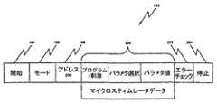
図4は前述のバッテリ給電式器具100と通信するためのメッセージ例の基本的様式を示しており、これらの器具は全て識別記憶装置108内に、好適にはその器具独自のアドレス(ID)を伴って事前構成されて、下記の動作モードの1つ、またはそれ以上で動作するようにされている。すなわち、(1)神経を刺激するため、すなわちマイクロスティミュレータとして、(2)生物学的なパラメタ監視のため、すなわちマイクロセンサとして、および/または、(3)他の皮下挿入器具へと再様式化した後で受信した信号を再送信するため、すなわちマイクロ・トランスポンダとして、である。指令メッセージ192は主として(1)開始部分194(メッセージ開始を示し、かつ送信機と受信機間のビット・タイミングを同期化させるための1ビット以上)と、(2)モード部分196(例えばスティミレータ、センサ、トランスポンダまたはグループ・モードのような動作モードを指定)と、(3)アドレス(ID)部分198(識別アドレス108またはプログラムされたグループIDのいずれかに対応)と、(4)データ欄部分200(前述の動作のための指令データを含む)と、(5)エラー・チェック部分202(例えば奇偶ビットを利用してメッセージ192の妥当性を保証する)と、(6)停止部分(メッセージ192の終了を指定する)とからなっている。これらの欄の基本的な定義は下記の表IIに示されている。これらの定義を用いて、各々の器具を患者の身体内の1つ以上の神経経路を制御するためのシステムの一部として、別個に構成、制御および/または制御することができる。In yet another mode of operation, the battery rechargeable instrument can be configured to operate as a main system controller that can change the operation of another subcutaneous insertion instrument, i.e., microstimulator and microsensor, in a closed loop control mode. it can.
FIG. 4 shows the basic format of an example message for communicating with the battery powered
モード アドレス(ID)
00 =スティミュレータ 8ビット識別アドレス
01 =センサ 8ビット識別アドレス
02 =トランスポンダ 4ビット識別アドレス
03 =グループ 4ビット・グループ識別アドレス
データ欄部分
プログラム/刺激 =動作モードの選択
パラメタ/
事前構成
選択 =プログラム・モードでプログラム可能パラメタを、または
その他のモードで事前構成された刺激または検出パラメタを
選択
パラメタ値 =プログラム値
表II−メッセージ・データ欄
Mode address (ID)
00 = stimulator 8-bit identification address 01 = sensor 8-bit identification address 02 = transponder 4-bit identification address 03 = group 4-bit group identification address
Data field partial program / stimulus = operation mode selection parameter /
Preconfiguration selection = Programmable parameters in program mode, or
Pre-configured stimulus or detection parameters in other modes
Selection parameter value = Program value
Table II-Message data column
加えて、各々の器具100は構成データ記憶装置132内に記憶されているグループID(例えば4ビット値)でプログラムすることができる。例えばマイクロスティミュレータのような器具100がその記憶されたグループIDと適合するグループIDメッセージを受信すると、器具はメッセージがその識別アドレス108に向けられたものであるかのように応答する。従って、複数個のマイクロスティミュレータ、例えば100aおよび100bには単一のメッセージで指令することができる。このモードは神経群の刺激に際して精密なタイミングを要する場合には特に有用である。 In addition, each
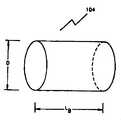
図5Aは回路に給電するバッテリ104を内蔵した、本発明に基づいて製造されたマイクロスティミュレータ100の側面図を示している。バッテリ104はマイクロスティミュレータ100を収納している(好適には密閉された)細長い密閉ハウジング206内に簡便に取付けられている。好適な器具100では、軸方向の寸法208は60mm未満であり、横方向の寸法207は6mm未満である。 FIG. 5A shows a side view of a
図5Aに示した実施例の場合、バッテリ104は好適には独自のバッテリ・ケース209内に収納され、バッテリ端子は(従来のAAバッテリと同様に)ケース209と一体の部品からなっている。このように、バッテリ104の(図5Aで見た)側部と左端部は例えば負のバッテリ端子のような一方のバッテリ端子210からなり、バッテリ104の右端部は例えば出力端子128として使用されるような正のバッテリ端子であってよい。有利なことには、このようなバッテリ・ケース209は導電性であるので、これをバッテリの一方の側から他方の側へと適切な回路ノードを接続するための、マイクロスティミュレータ100内の回路用の導電体として役立てることができる。より具体的には、図5Aに示した構造では、バッテリ端子210は器具のハウジング206内に格納された全ての回路のために接地点もしくはノードとして機能することができる。従って、電気回路の観点からは回路のアースに簡便に接続されているマイクロスティミュレータ100の左端部の電極112aからのステム212は、バッテリ104の左端部と簡便に接触できる。そこで、バッテリ104の右側の近傍、またはバッテリのリム上で、すなわちハウジング206の右端部内のバッテリ104の右側の(好適には例えばコントローラ106および刺激回路110のような器具の電力消費回路として実施されている)単数または複数個のICチップ216の近傍で、この同じ回路のアース接続を利用できる。このようにしてバッテリ104の導電性ケース209を利用することによって、器具100の右の回路を器具100の左側の電極112aと電気的に接続するために、バッテリ104の周囲に別個の配線、またはその他の導体を通したり取付ける必要がない。 In the embodiment shown in FIG. 5A, the
図5Bは、マイクロスティミュレータ100'が(身体組織をDC電流が流れることを防止するために使用される)内部結合コンデンサ183を含んでいることを除いては、図5Aに示した器具100と実質的に同一のバッテリ給電式のマイクロスティミュレータ100'を示している。図5Bに示した実施例では内部結合コンデンサ183が使用されているが、その理由はマイクロスティミュレータ100'によって使用されているマイクロスティミュレータの電極112aおよび112bの双方が同じ材料、すなわちイリジウムから製造されているからである。これに対して、図5Aに示したマイクロスティミュレータ100用の電極112aおよび112bは異なる材料から、すなわちイリジウム(電極112b)およびタンタル(電極112a)からなっており、このような材料は性質上、双方の間にかなりのキャパシタンスをもたらすことにより、DC電流の流れを防止する。例えば米国特許明細書第5,324,316号の第11段、26−33行を参照されたい。 FIG. 5B shows the
図5Cおよび5Dは密閉されたハウジング206、バッテリ104、コンデンサ183および(1つ、またはそれ以上のICチップ216上に実施さている)内蔵回路の現時点で好適な構造の2つの破断側面図である。現時点で好適なこのような構造では、ハウジング206は電極112aを形成する第1の端部キャップにろう付け262を介してブレージングされた絶縁セラミック管260からなっている。セラミック管260の他端には、これもセラミック管260にブレージングされた金属リング264が備えられている。内部の回路、すなわちコンデンサ183、バッテリ104、ICチップ216およびばね266は電極112bを形成する反対側の第2端部キャップに取付けられている。コンデンサ183を端部キャップ112aに接着するために導電性エポキシの小滴が使用され、かつ接着剤と共にばね266によって所定位置に保持されている。好適には、ICチップ216は回路板268上に実装され、その上には半円形の細長いフェライト板270が取付けられている。コイル116はフェライト板270の周囲に巻回され、かつICチップ216に取付けられている。内部に進入する水分を吸収することによって器具100の密閉性を高めるために、好適にはばね266の周囲に取付けられたゲッタ272が使用されている。実施例のゲッタ272はその水分容積の70倍を吸収する。回路と端部キャップ112bとを共に保持しつつ、端部キャップ112bをリング164にレーザー溶接することもできる。加えて、身体組織に対する接続インピーダンスを最小限にするため、好適にはプラチナ、イリジウム、またはプラチナ−イリジウムのディスク、またはプレート274が器具100の端部キャップに溶接される。 FIGS. 5C and 5D are two cutaway side views of a presently preferred structure of a sealed
以下に図6−8の説明に関連してバッテリ104をより詳細に説明する。好適には、バッテリ104は好適にはエネルギ密度が約240mW時/cm3のバッテリから構成された、少なくとも1マイクロワット時の電力容量を供給するような適宜の材料からなっている。Li−Iのバッテリによって有利にこのようなエネルギ密度が得られる。あるいは、Li−I−Snのバッテリによって360mW時/cm3にも及ぶエネルギ密度が得られる。これらのバッテリのどれでも、または少なくとも1マイクロワット時の電力容量が得られる他のバッテリのどれでも本発明に使用してもよい。The
バッテリの実施例のバッテリ電圧Vは公称3.6ボルトであり、これはICチップ(単数または複数)216、および/または器具100内のその他の電子回路を実施するために使用されるCMOS回路を動作するために特に適している。バッテリ電圧Vは一般に、好適には約2.55ボルト以下に放電されてはならず、その場合には永久的な損傷が生ずることがある。同様に、バッテリ104は好適には約4.2ボルト以上のレベルまでは充電されてはならず、その場合にも永久的な損傷が生ずることがある。従って、前述の充電回路122は損傷を生ずる可能性がある放電、または過充電を避けるために利用される。 The battery voltage V of the battery embodiment is nominally 3.6 volts, which is a CMOS circuit used to implement the IC chip (s) 216 and / or other electronic circuitry within the
次に図6−9を参照して、皮下挿入器具100内で使用されるバッテリ104に関するその他の点を詳細に説明する。基本的に、バッテリ104は多くの形態を取ることができ、利用できる小さい容積内にバッテリが適合できるかぎり、どの形態のものを使用してもよい。前述のように、バッテリ104は一次電池でも、再充電可能な電池でもよい。一次電池には所定のエネルギ出力において寿命が長いという利点があるが、再充電できないという欠点がある(これは、エネルギを一旦使い尽くすと、器具100はもはや機能しないことを意味する)。しかし、損傷した、または衰弱した筋肉組織に施される一回限りの筋肉リハビリ治療のような多くの用例では、例えばマイクロスティミュレータのような器具100は短期間しか使用する必要がない(その後で、器具は外植又は破棄され、または良性の医療器具のように単に皮下挿入したままで放置することができる)。その他の用例では、マイクロスティミュレータによる組織の刺激は反復性の刺激であるので、再充電可能なバッテリが明らかに好適な種類のエネルギ選択である。 6-9, other points regarding the
皮下挿入器具100のバッテリ104として再充電可能なバッテリを使用することに関する考察は特に「再充電可能なバッテリ、応用ハンドブック」という書籍(設計技師用のEDNシリーズ、ゲーツ・エネルギ・プロダクト社の技術マーケッティング・スタッフ編、ブッターワース・ハイネマン、1992年刊)に記載されている。再充電可能なバッテリの基本的な考察はいずれも高いエネルギ密度と長い寿命に関するものである。リチウムをベースにしたバッテリは歴史的には主として再充電不能バッテリとして使用されてきたものの、最近では再充電可能なバッテリとして市販されているようである。リチウムをベースにしたバッテリのエネルギ密度は標準的には240mW時/cm3ないし360mW時/cm3である。一般に、エネルギ密度は高いほど良いが、1マイクロワット時以上の電力容量を生ずるエネルギ密度が得られるものならば、本発明にはどのバッテリ構造でも適している。The discussion regarding the use of a rechargeable battery as the
本発明の器具100でバッテリ104を使用する際に直面するより困難なハードルの1つは、バッテリを内部に挿入しなければならないハウジング内部のサイズまたは容積が比較的小さいことに関するものである。本発明に基づいて製造された標準形の器具100は好適には長さが約60mm未満であり、直径が6mm未満であり、かつ、例えば長さ15mmで外径が2.2mm(従って内径は約2mm)のより小型の実施例も含まれる。器具のハウジング206内部で利用できる容積の僅か1/4ないし1/2しかバッテリ用に利用できないことを考慮すれば、器具100にはバッテリのための容積がいかに小さく、ひいてはバッテリの蓄電容量がいかに少ないかがより明確に理解されよう。 One of the more difficult hurdles encountered when using the
本発明の器具100、例えばマイクロスティミュレータは一般に僅かな電力料しか消費しないように設計されている。マイクロスティミュレータ100の電力消費回路の基本的な電力排出は電極112と接触する組織に印加される刺激電流である。衝撃係数が極めて低い標準的な刺激電流が図10に示されている。例えば、神経を基本的に連続的に刺激するための波形の例は、50ミリ秒(T1)毎に、すなわち20へルツの比率で発生する0.2ミリ秒のパルス(T2)でよい。The
このような源流パルスのピーク値が5ma(Ip)であり、3.6ボルト(V)の電位で供給された場合、器具によって供給されるワット(W)単位のピーク出力電力(P)は、
P=IV
=(5ma)(3.6V)=18mWであり、
衝撃係数の関数である平均出力電力は、
P(平均)=18mWx0.2/50=0.072mW=72μWである。
長さLが15mmで内径が2mm(従って半径rは1mm)である標準サイズのマイクロスティミュレータを使用する場合、また、利用できる長さの1/3、すなわち5mmをバッテリ(LB)用に利用できるものと想定すると、バッテリの容積は下記のようなものになろう。
VolBAT=πr2LB
=π(1mm)2(5mm)(1cm3/1000mm3)
=0.0157cm3
このように、バッテリがエネルギ密度240mW時/cm3を呈する材料から製造されたものとすると、完全に充電されたバッテリは72μW(0.072mW)の公称負荷を、
(240mW時/cm3)(0.0157cm3)/(0.072mW)=52.3時間の期間だけサポートすることが判り、これは約2.2日に相当する。このように、少なくとも2の安全係数を用いた場合、バッテリは毎日再充電する必要がある。When such a source pulse has a peak value of 5 ma (Ip ) and is supplied at a potential of 3.6 volts (V), the peak output power (P) in watts (W) supplied by the instrument is ,
P = IV
= (5ma) (3.6V) = 18 mW,
The average output power as a function of impact coefficient is
P (average) = 18 mW × 0.2 / 50 = 0.072 mW = 72 μW.
When using a standard size microstimulator with a length L of 15 mm and an inner diameter of 2 mm (and thus a radius r of 1 mm), and also 1/3 of the available length, ie 5 mm, for the battery (LB ) Assuming that it can be used, the battery volume would be as follows:
VolBAT = πr2 LB
= Π (1mm) 2 (5mm ) (
= 0.0157cm3
Thus, assuming that the battery is manufactured from a material that exhibits an energy density of 240 mW hr / cm3 , a fully charged battery has a nominal load of 72 μW (0.072 mW),
(240 mW at/ cm 3) (0.0157cm 3) / found to be only support period (0.072mW) = 52.3 hr, which corresponds to about two. Two days. Thus, with a safety factor of at least 2, the battery needs to be recharged daily.
しかし、別の用例では例えば骨の成長刺激のように衝撃係数がより高いにも関わらず大幅に少ない励振電流(例えば1μa)を必要とする場合もあれば、または毎日数分の神経刺激しか必要としない例えば嚢状器官の刺激、またはその他の用例のように、場合によってはより大きい励振電流(例えば40ma)を必要とする場合もある。本発明の実施例で使用されるバッテリには最小の仕様として1ミリワット時の値が選択されている。しかし、前述のように、本発明の実施例には大幅に高い容量のバッテリも含まれるので、このような実施例はより広範囲の用例を包括することができる。 However, other applications may require significantly less excitation current (
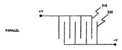
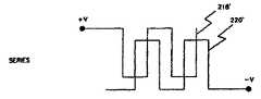
次に図6Aおよび6Bを参照すると、バッテリ板または電極を並列または直列に接続できる態様が図示されている。負の電極220に差し込んだ、もしくは積層した正の電極218の並列接続が図6Aに示されている。このように差し込んだ電極の直列接続が図6Bに示されている。一般に、並列接続における抵抗は直列接続における抵抗よりも低く、これはバッテリの時間定数、すなわち所定の電流レベルにバッテリを放電または充電するのに要する時間は、並列接続の場合よりも直列接続の場合の方が高いこと、すなわち時間が長いことを意味している。放電の時間定数は基本的に(仕様時にはバッテリから僅かな電流しか排出されないので)本発明の目的には重要ではないが、(少なくとも部分的にバッテリを再充電するのにどの程度の時間を要するかがそれによって決まるので)充電の時間定数は重要である。 Referring now to FIGS. 6A and 6B, there is illustrated how battery plates or electrodes can be connected in parallel or in series. A parallel connection of
図7Aはバッテリ104の標準的な円筒形の形状を示している。一般に、このような形状には横方向の寸法、すなわち直径Dと、軸方向の寸法、すなわち長さLがある。しかし、その他の形状も可能であり、有利である可能性もあることが判る。例えば、長方形、または柱形の形状のバッテリを使用することもでき、それには例えばハウジング206の周囲の内部領域に実装された刺激回路110用のコントローラ106のような電力消費回路と共に、ハウジング206の全長に延びるバッテリも含まれる。 FIG. 7A shows the standard cylindrical shape of the
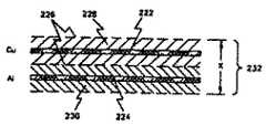
バッテリ104内で使用される電極は一対で配置されており、図7Bに示すように、電極、もしくはプレートが間に電解質を配して対向する関係で取付けられた基本的な位置関係を有している。第1電極222は例えば銅(Cu)のような第1の材料からなっている。第2電極224は第2の材料、例えばアルミニウム(Al)からなっている。ポリプロピレン製のセパレータ226が2つの電極を分離している。セパレータ226は物理的に分離し、かつ電極が互いに接触することを防止することによって、電極間に電子電流が流れることを防止するが、イオンが間を通過できるような間隙を有しており、従ってイオン電流が電極間を流れることができる。適宜の電解ペースト228が電極222を囲んでいる。別の適宜の電解ペースト230が電極224を囲んでいる。このような電解質を製造するのに適した材料は文献に記載されている。標準的にはセパレータと電解ペーストを含む一対の電極の厚さXは0.010ないし0.024インチ程度であり、但しCuとAlの電解の厚さが各々約0.001インチ、セパレータ226の厚さが約0.001インチ未満、そして電極の両側の電解ペーストの厚さが約0.002ないし0.008インチである。セパレータ226、および電解ペースト228と230を含む2個の電極222と224の組合わせによって電極層232が形成される。バッテリは電極層232を利用できるバッテリ用の容積に効率的に配置し、適宜の電流コレクタ(コンダクタ)を正の電極222と負の電極224とに取付けて、これと電気的に接触するようにすることによって形成される。 The electrodes used in the
図8A−8Fに示した様々な図面は本発明に必要な円筒形のバッテリ104を形成するために用いられる様々な構造を示している。個々の図面はそれぞれバッテリ容器の(例えば上から見た)横断面図の下の、バッテリ容器の側面断面図である。
図8Aでは、電極層222と224の長さは螺旋状に巻き込まれ、円筒形のコンテナ、もしくはケース234内に長手方向に挿入されている。導電性のワイヤ、すなわちタブ236と238が電極222と224のそれぞれに取付けられ、バッテリ端子としての役割を果たす。The various drawings shown in FIGS. 8A-8F illustrate the various structures used to form the
In FIG. 8A, the lengths of
図8Bでは、円形の正の電極222と負の電極224の並列接続された差込み式の積層が導電性コンテナ234内に配置されている。セパレータ層(図示せず)が必要に応じて電極の間に配置される。正の電極222は各々、コンテナ234と接触する母線に接続されている。負の電極224はそれぞれ、コンテナ234の導電性の蓋239と接触する母線に接続されている。あるいは、負の電極224をコンテナと接触する母線と接続し、負の電極224を蓋239と接触する母線と接続することもできる。電極をコンテナ234または蓋239に接続する母線用の管路を形成するためにノッチ、もしくは切り込み240を各電極に設けてもよい。絶縁リング241によって、蓋239がケース234と短絡したり、これに接触しないことが確実にされる。このようにしてコンテナ234と蓋239はバッテリ端子として機能する。 In FIG. 8B, a plug-in stack of circular
図8Cは直列接続された差込み式積層を示している。直列接続であることを除いては、図8Cに示した構成は図8Bに示したものと同一である。
図8Dは幅が可変的な長方形の電極条片の並列接続された差込み式の縦の積層を示している。負の電極224は各々が蓋239に接続されている。正の電極222は各々がコンテナ234に接続されている。このようにしてコンテナ234と蓋239とはバッテリ端子としての機能を果たす。
図8Eは電極222と224とが互いの内側に適合する異なる直径の同心管からなっている並列接続の同心電極構造を示している。FIG. 8C shows plug-in stacks connected in series. Except for the serial connection, the configuration shown in FIG. 8C is the same as that shown in FIG. 8B.
FIG. 8D shows a plug-in vertical stack of parallel strips of variable width rectangular electrode strips. Each
FIG. 8E shows a parallel connected concentric electrode structure in which
図8Fは電極222と224とが例えばCuまたはAlのような適宜の材料からなる(長さがほぼLBの)ワイヤから実施されており、負の電極224が正の電極222に隣接するようなアレイで配置されている。セパレータ・スリーブ226'が電極ワイヤ、例えば負の電極ワイヤの上に配置されている。適宜の電解ペーストがそれぞれの電極の周囲の空洞を満たしている。必要に応じて、セパレータ226'は適宜の電極の周囲に適宜の電解ペーストを保持し、別の電解ペーストがその領域の近くに入ることを防止している。負のワイヤ224はコンテナ234の底部に取付けられ、正のワイヤ電極222は蓋239に取付けられている。Figure 8F is implemented made of an appropriate material, such as the
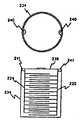
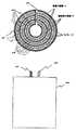
図8Gは図8Eと同様であるが、円筒形電極が間隙、もしくはスリット242を含んでいる、並列接続された円筒形電極の実施例を示しており、間隙242の両側の円筒形電極222と224とはバッテリ用の電気端子の役割を果たすタブ244および246の共通の接続点を形成している。電極222と224とは適切なセパレータ248によって分離されている。間隙242によって電極内に渦電流が流れることが最小限に抑止される。図8Gに示した実施例では、4個の同心円筒電極222があり、そのうちの外側の電極(最大直径)はバッテリ・ケース234として機能し、3個の同心電極224が電極222の間に差し込まれ、6個の同心円筒形のセパレータ層248が各々の電極222または224を隣接する電極から分離している。 FIG. 8G is similar to FIG. 8E, but shows an embodiment of the cylindrical electrodes connected in parallel, where the cylindrical electrodes include gaps or slits 242, and the
変調された指令信号部分を有する磁気信号の部分が加熱したり、またはその他の態様で分路する原因になり得る、バッテリ内での渦電流の流れを最小限にすることが一般に好適である。従って、例えば図8A−8Dおよび8Fに示した構造のように、導通性の閉ループを形成する陽極プレートでバッテリを形成しないことによって渦電流は最小限に抑止される。しかし、加熱が望ましい場合も考えられ、その場合は図8Eの実施例が望ましいであろう。 It is generally preferred to minimize the flow of eddy currents in the battery, which can cause a portion of the magnetic signal having a modulated command signal portion to heat up or otherwise shunt. Thus, eddy currents are minimized by not forming the battery with an anode plate that forms a conductive closed loop, such as the structure shown in FIGS. 8A-8D and 8F. However, it may be desirable to heat, in which case the embodiment of FIG. 8E would be desirable.
次に図9Aを参照すると、図8Cに示したような直列接続の電極積層として安価な電極を形成する態様が示されている。1組の電極250を公知のような適宜のパターンで厚さ0.002インチの薄板から打ち抜き、切断することができる。相補形の電極252も図示のように同様に打ち抜きおよび切断できる。各組の電極は適宜のタブ254によって接続された基本的に円形の電極を含んでいる。タブ254は1つの電極から次の電極へと離隔されている。次に電極のセットは、離隔されたタブ254が図9Bに示すように互いに妨害しないように折り曲げられ、かつ互いに差し込まれる。各組の電極250、252は次にコンテナ234内に挿入され、セパレータ・スリーブが1組の電極の上方に挿入され、各組の電極と対応するバッテリ端子との間で適宜の電気接続が行われる。 Next, referring to FIG. 9A, there is shown an aspect in which an inexpensive electrode is formed as a series-connected electrode stack as shown in FIG. 8C. A set of
ここに開示した発明は特定の実施例と用例について説明してきたが、当業者には請求の範囲に記載した本発明の範囲から離れることなく多くの修正と変化形が可能であろう。例えば、主として磁気および超音波通信手段を説明してきたが、その他の通信手段も可能である。代替実施例では、皮下挿入器具100は電流パルスの導通、すなわち電極を通って発される変調された亜刺激しきい値電流パルス(筋肉や神経を刺激しないパルス)、赤外線を介しても通信可能であり、または皮下挿入器具を皮膚のすぐ下に挿入する場合は、透光性の光学手段を使用することができる。加えて、光学的(例えば太陽電池)および機械的装置を含む他の手段を使用して皮下挿入器具内のバッテリに充電することができ、または適宜の一次電池を形成するために核エネルギの実施例を採用することもできる。 Although the invention disclosed herein has been described with reference to specific embodiments and examples, those skilled in the art will recognize many modifications and variations without departing from the scope of the present invention as set forth in the claims. For example, although magnetic and ultrasonic communication means have been described primarily, other communication means are possible. In an alternative embodiment, the
Claims (2)
Translated fromJapanese軸方向の寸法が60mm未満で、横方向の寸法が6mm未満である密閉された細長いハウジングと、
前記ハウジング内に少なくとも一部が配置された、少なくとも1つの電力入力端子を有する電力消費回路と、
少なくとも1つの電力出力端子を有し、少なくとも1マイクロワット時のエネルギ有することができる再充電可能なバッテリと、
前記電力出力端子を前記電力入力端子と電気的に結合して、前記回路に電力を供給するための手段と、
患者の身体の外部で発生された電磁エネルギに応動して充電電流を発生するための充電回路と、
前記充電電流を前記バッテリに印加する手段と、
患者の身体の外部で発生された前記バッテリの充電状態を呼び掛ける信号を受信する手段と、
前記バッテリの充電状態を呼び掛ける信号に応じて、バッテリの充電状態を示す信号を送信する手段と、を備えてなる器具と、
患者の身体の外部に配置されるコイルと、
前記コイルをAC電流で付勢して、前記充電電流にエネルギを供給する交番磁界及び前記バッテリの充電状態を呼び掛ける信号を発生するための手段と、
を備えてなり、前記充電電流にエネルギを供給する交番磁界の供給と、前記患者の皮下に挿入するように構成された器具から発生されるバッテリの充電状態を示す信号の送信とは、前記バッテリの充電状態を呼び掛ける信号を境にして、時分割されていることを特徴とするシステム。An instrument configured to be inserted under the skin of a patient,
A sealed elongated housing having an axial dimension of less than 60 mm and a transverse dimension of less than 6 mm;
A power consuming circuit having at least one power input terminal disposed at least partially within the housing;
A rechargeable battery having at least one power output terminal and capable of having at least 1 microwatt hour of energy;
Means for electrically coupling the power output terminal with the power input terminal to supply power to the circuit;
A charging circuit for generating a charging current in response to electromagnetic energy generated outside the patient's body;
Means for applying the charging current to the battery;
Means for receiving a signal calling for a state of charge of the battery generated outside the patient's body;
Means for transmitting a signal indicating the state of charge of the battery in response to a signal calling for the state of charge of the battery ; and
A coil placed outside the patient's body;
Means for energizing the coil with an AC current to generate an alternating magnetic field for supplying energy to the charging currentand a signal calling for a state of charge of the battery ;
TheRi Na includesthe supply of an alternating magnetic field for supplying energy to the charging current, the transmission of the signal indicating the state of charge of the battery which is generated from the instrument configured to insert the skin of the patient, the A systemthat is time-divided with a signal calling for the state of charge of the battery as a boundary .
ケースと、
該ケース内に実装された第1導電性プレートと、
該第1プレートに対して対向し、間隔を隔てた位置関係で前記ケース内に実装された第2導電性プレートと、
前記第1と第2のプレートの間に配置された電解質とを含み、
前記プレートが間隙を含み、内部の渦電流を抑止するように形成されていることを特徴とする請求項1に記載のシステム。The battery is
Case and
A first conductive plate mounted in the case;
A second conductive plate facing the first plate and mounted in the case in a positional relationship spaced apart;
An electrolyte disposed between the first and second plates;
The system of claim 1, wherein the plate includes a gap and is configured to inhibit internal eddy currents.
Applications Claiming Priority (1)
| Application Number | Priority Date | Filing Date | Title |
|---|---|---|---|
| US3916497P | 1997-02-26 | 1997-02-26 |
Related Parent Applications (1)
| Application Number | Title | Priority Date | Filing Date |
|---|---|---|---|
| JP53781598ADivisionJP2001513679A (en) | 1997-02-26 | 1998-02-25 | Battery powered patient subcutaneous insertion device |
Publications (2)
| Publication Number | Publication Date |
|---|---|
| JP2008023353A JP2008023353A (en) | 2008-02-07 |
| JP4485556B2true JP4485556B2 (en) | 2010-06-23 |
Family
ID=21904004
Family Applications (2)
| Application Number | Title | Priority Date | Filing Date |
|---|---|---|---|
| JP53781598APendingJP2001513679A (en) | 1997-02-26 | 1998-02-25 | Battery powered patient subcutaneous insertion device |
| JP2007230996AExpired - LifetimeJP4485556B2 (en) | 1997-02-26 | 2007-09-06 | Battery powered patient subcutaneous insertion device |
Family Applications Before (1)
| Application Number | Title | Priority Date | Filing Date |
|---|---|---|---|
| JP53781598APendingJP2001513679A (en) | 1997-02-26 | 1998-02-25 | Battery powered patient subcutaneous insertion device |
Country Status (7)
| Country | Link |
|---|---|
| US (1) | US6185452B1 (en) |
| EP (3) | EP1647300A3 (en) |
| JP (2) | JP2001513679A (en) |
| AU (1) | AU6667698A (en) |
| CA (1) | CA2281880C (en) |
| DE (1) | DE69832713T2 (en) |
| WO (1) | WO1998037926A1 (en) |
Cited By (1)
| Publication number | Priority date | Publication date | Assignee | Title |
|---|---|---|---|---|
| US12433991B2 (en) | 2022-08-12 | 2025-10-07 | Luminoah, Inc. | Wearable fluid delivery system |
Families Citing this family (735)
| Publication number | Priority date | Publication date | Assignee | Title |
|---|---|---|---|---|
| US9289618B1 (en) | 1996-01-08 | 2016-03-22 | Impulse Dynamics Nv | Electrical muscle controller |
| US7167748B2 (en) | 1996-01-08 | 2007-01-23 | Impulse Dynamics Nv | Electrical muscle controller |
| US20050075682A1 (en)* | 1997-02-26 | 2005-04-07 | Schulman Joseph H. | Neural device for sensing temperature |
| US8684009B2 (en)* | 1997-02-26 | 2014-04-01 | Alfred E. Mann Foundation For Scientific Research | System for determining relative distance(s) and/or angle(s) between at least two points |
| US7114502B2 (en)* | 1997-02-26 | 2006-10-03 | Alfred E. Mann Foundation For Scientific Research | Battery-powered patient implantable device |
| US6208894B1 (en)* | 1997-02-26 | 2001-03-27 | Alfred E. Mann Foundation For Scientific Research And Advanced Bionics | System of implantable devices for monitoring and/or affecting body parameters |
| US7107103B2 (en)* | 1997-02-26 | 2006-09-12 | Alfred E. Mann Foundation For Scientific Research | Full-body charger for battery-powered patient implantable device |
| US8555894B2 (en)* | 1997-02-26 | 2013-10-15 | Alfred E. Mann Foundation For Scientific Research | System for monitoring temperature |
| US6164284A (en)* | 1997-02-26 | 2000-12-26 | Schulman; Joseph H. | System of implantable devices for monitoring and/or affecting body parameters |
| US6695885B2 (en)* | 1997-02-26 | 2004-02-24 | Alfred E. Mann Foundation For Scientific Research | Method and apparatus for coupling an implantable stimulator/sensor to a prosthetic device |
| DE69841076D1 (en)* | 1997-03-27 | 2009-10-01 | Advanced Bionics Corp | SYSTEM OF IMPLANTABLE DEVICES FOR MONITORING AND INFLUENCING BODY PARAMETERS |
| EP1702648B1 (en)* | 1997-03-27 | 2015-03-18 | The Alfred E Mann Foundation for Scientific Research | System of implantable devices for monitoring and/or affecting body parameters |
| ES2224420T3 (en)* | 1997-08-01 | 2005-03-01 | Alfred E. Mann Foundation For Scientific Research | IMPLANTABLE DEVICE WITH IMPROVED POWER AND BATTERY RECHARGE CONFIGURATION. |
| EP1424098B1 (en)* | 1997-08-01 | 2008-12-03 | Alfred E. Mann Foundation For Scientific Research | Implantable device with improved battery recharging and powering configuration |
| AU1093099A (en) | 1997-10-17 | 1999-05-10 | Penn State Research Foundation; The | Muscle stimulating device and method for diagnosing and treating a breathin g disorder |
| US20030036746A1 (en)* | 2001-08-16 | 2003-02-20 | Avi Penner | Devices for intrabody delivery of molecules and systems and methods utilizing same |
| US7890176B2 (en)* | 1998-07-06 | 2011-02-15 | Boston Scientific Neuromodulation Corporation | Methods and systems for treating chronic pelvic pain |
| US6735474B1 (en)* | 1998-07-06 | 2004-05-11 | Advanced Bionics Corporation | Implantable stimulator system and method for treatment of incontinence and pain |
| US6941171B2 (en) | 1998-07-06 | 2005-09-06 | Advanced Bionics Corporation | Implantable stimulator methods for treatment of incontinence and pain |
| DE19832628C2 (en)* | 1998-07-21 | 2000-10-12 | Daimler Chrysler Ag | Transponder arrangement |
| US6308101B1 (en) | 1998-07-31 | 2001-10-23 | Advanced Bionics Corporation | Fully implantable cochlear implant system |
| US6240316B1 (en) | 1998-08-14 | 2001-05-29 | Advanced Bionics Corporation | Implantable microstimulation system for treatment of sleep apnea |
| US6872187B1 (en) | 1998-09-01 | 2005-03-29 | Izex Technologies, Inc. | Orthoses for joint rehabilitation |
| IL127481A (en)* | 1998-10-06 | 2004-05-12 | Bio Control Medical Ltd | Incontinence treatment device |
| US6652449B1 (en) | 1998-10-06 | 2003-11-25 | Bio Control Medical, Ltd. | Control of urge incontinence |
| US20020041987A1 (en)* | 1998-10-23 | 2002-04-11 | Joseph H. Schulman | Prismatic zincair battery for use with biological stimulator |
| US8346363B2 (en)* | 1999-03-05 | 2013-01-01 | Metacure Limited | Blood glucose level control |
| US8019421B2 (en)* | 1999-03-05 | 2011-09-13 | Metacure Limited | Blood glucose level control |
| WO2006073671A1 (en) | 2004-12-09 | 2006-07-13 | Impulse Dynamics Nv | Protein activity modification |
| US20040249421A1 (en)* | 2000-09-13 | 2004-12-09 | Impulse Dynamics Nv | Blood glucose level control |
| US9101765B2 (en)* | 1999-03-05 | 2015-08-11 | Metacure Limited | Non-immediate effects of therapy |
| US8666495B2 (en)* | 1999-03-05 | 2014-03-04 | Metacure Limited | Gastrointestinal methods and apparatus for use in treating disorders and controlling blood sugar |
| US8700161B2 (en)* | 1999-03-05 | 2014-04-15 | Metacure Limited | Blood glucose level control |
| US6166518A (en)* | 1999-04-26 | 2000-12-26 | Exonix Corporation | Implantable power management system |
| US6635048B1 (en) | 1999-04-30 | 2003-10-21 | Medtronic, Inc. | Implantable medical pump with multi-layer back-up memory |
| US7177690B2 (en)* | 1999-07-27 | 2007-02-13 | Advanced Bionics Corporation | Implantable system having rechargeable battery indicator |
| US6516227B1 (en) | 1999-07-27 | 2003-02-04 | Advanced Bionics Corporation | Rechargeable spinal cord stimulator system |
| US7295878B1 (en) | 1999-07-30 | 2007-11-13 | Advanced Bionics Corporation | Implantable devices using rechargeable zero-volt technology lithium-ion batteries |
| US6553263B1 (en)* | 1999-07-30 | 2003-04-22 | Advanced Bionics Corporation | Implantable pulse generators using rechargeable zero-volt technology lithium-ion batteries |
| US6471635B1 (en) | 2000-02-10 | 2002-10-29 | Obtech Medical Ag | Anal incontinence disease treatment with controlled wireless energy supply |
| US6482145B1 (en) | 2000-02-14 | 2002-11-19 | Obtech Medical Ag | Hydraulic anal incontinence treatment |
| US6450173B1 (en) | 1999-08-12 | 2002-09-17 | Obtech Medical Ag | Heartburn and reflux disease treatment with controlled wireless energy supply |
| US6464628B1 (en) | 1999-08-12 | 2002-10-15 | Obtech Medical Ag | Mechanical anal incontinence |
| US7949395B2 (en)* | 1999-10-01 | 2011-05-24 | Boston Scientific Neuromodulation Corporation | Implantable microdevice with extended lead and remote electrode |
| US20070203531A9 (en)* | 1999-12-03 | 2007-08-30 | Medtronic, Inc. | Heart rate variability control of gastric electrical stimulator |
| AU764705B2 (en) | 2000-02-10 | 2003-08-28 | Implantica Patent Ltd. | Urinary incontinence treatment with wireless energy supply |
| ATE391468T1 (en)* | 2000-02-10 | 2008-04-15 | Potencia Medical Ag | MECHANICAL DEVICE FOR IMPOTENCY TREATMENT |
| CA2635435C (en)* | 2000-02-10 | 2010-05-25 | Potencia Medical Ag | Controlled urinary incontinence treatment |
| CA2396224C (en)* | 2000-02-11 | 2011-07-12 | Potencia Medical Ag | Controlled impotence treatment |
| ATE416743T1 (en)* | 2000-02-11 | 2008-12-15 | Potentica Ag | DEVICE WITH ENERGY CONVERSION MEANS FOR TREATING IMPOTENCY |
| WO2001047440A2 (en)* | 2000-02-14 | 2001-07-05 | Potencia Medical Ag | Male impotence prosthesis apparatus with wireless energy supply |
| US7442165B2 (en) | 2000-02-14 | 2008-10-28 | Obtech Medical Ag | Penile prosthesis |
| US20030100929A1 (en) | 2000-02-14 | 2003-05-29 | Peter Forsell | Controlled penile prosthesis |
| US6582441B1 (en) | 2000-02-24 | 2003-06-24 | Advanced Bionics Corporation | Surgical insertion tool |
| US8155752B2 (en) | 2000-03-17 | 2012-04-10 | Boston Scientific Neuromodulation Corporation | Implantable medical device with single coil for charging and communicating |
| US6650943B1 (en) | 2000-04-07 | 2003-11-18 | Advanced Bionics Corporation | Fully implantable neurostimulator for cavernous nerve stimulation as a therapy for erectile dysfunction and other sexual dysfunction |
| US6574511B2 (en)* | 2000-04-21 | 2003-06-03 | Medtronic, Inc. | Passive data collection system from a fleet of medical instruments and implantable devices |
| US6596439B1 (en)* | 2000-04-26 | 2003-07-22 | Quallion Llc | Lithium ion battery capable of being discharged to zero volts |
| US7167756B1 (en) | 2000-04-28 | 2007-01-23 | Medtronic, Inc. | Battery recharge management for an implantable medical device |
| US6850803B1 (en) | 2000-06-16 | 2005-02-01 | Medtronic, Inc. | Implantable medical device with a recharging coil magnetic shield |
| US6505077B1 (en) | 2000-06-19 | 2003-01-07 | Medtronic, Inc. | Implantable medical device with external recharging coil electrical connection |
| EP1166820B1 (en) | 2000-06-19 | 2009-09-30 | Medtronic, Inc. | Implantable medical device with external recharging coil |
| US8046076B2 (en) | 2000-06-20 | 2011-10-25 | Boston Scientific Neuromodulation Corporation | Treatment of mood and/or anxiety disorders by electrical brain stimulation and/or drug infusion |
| WO2001097906A2 (en) | 2000-06-20 | 2001-12-27 | Advanced Bionics Corporation | Apparatus for treatment of mood and/or anxiety disorders by electrical brain stimulation and/or drug infusion |
| US20020140559A1 (en)* | 2001-03-29 | 2002-10-03 | Zhou Peter Y. | System and method for remotely monitoring |
| US7054689B1 (en) | 2000-08-18 | 2006-05-30 | Advanced Bionics Corporation | Fully implantable neurostimulator for autonomic nerve fiber stimulation as a therapy for urinary and bowel dysfunction |
| US6871099B1 (en) | 2000-08-18 | 2005-03-22 | Advanced Bionics Corporation | Fully implantable microstimulator for spinal cord stimulation as a therapy for chronic pain |
| US6862479B1 (en) | 2000-08-30 | 2005-03-01 | Advanced Bionics Corporation | Spinal cord stimulation as a therapy for sexual dysfunction |
| US6591139B2 (en) | 2000-09-06 | 2003-07-08 | Advanced Bionics Corporation | Low-power, high-modulation-index amplifier for use in battery-powered device |
| WO2002022205A1 (en) | 2000-09-13 | 2002-03-21 | Alfred E. Mann Institute For Biomedical Engineering At The University Of Southern California | Method and apparatus for conditioning muscles during sleep |
| WO2002032499A1 (en)* | 2000-09-14 | 2002-04-25 | Alfred E. Mann Institute For Biomedical Engineering At The University Of Southern California | Method and apparatus to treat disorders of gastrointestinal peristalsis |
| US6845267B2 (en) | 2000-09-28 | 2005-01-18 | Advanced Bionics Corporation | Systems and methods for modulation of circulatory perfusion by electrical and/or drug stimulation |
| US6745077B1 (en) | 2000-10-11 | 2004-06-01 | Advanced Bionics Corporation | Electronic impedance transformer for inductively-coupled load stabilization |
| EP1342289B1 (en)* | 2000-10-11 | 2010-05-19 | Alfred E. Mann Foundation for Scientific Research | Improved antenna for miniature implanted medical device |
| US6764446B2 (en)* | 2000-10-16 | 2004-07-20 | Remon Medical Technologies Ltd | Implantable pressure sensors and methods for making and using them |
| US7283874B2 (en)* | 2000-10-16 | 2007-10-16 | Remon Medical Technologies Ltd. | Acoustically powered implantable stimulating device |
| US7024248B2 (en)* | 2000-10-16 | 2006-04-04 | Remon Medical Technologies Ltd | Systems and methods for communicating with implantable devices |
| US7198603B2 (en)* | 2003-04-14 | 2007-04-03 | Remon Medical Technologies, Inc. | Apparatus and methods using acoustic telemetry for intrabody communications |
| US7440806B1 (en) | 2000-11-21 | 2008-10-21 | Boston Scientific Neuromodulation Corp. | Systems and methods for treatment of diabetes by electrical brain stimulation and/or drug infusion |
| US6922590B1 (en) | 2000-11-21 | 2005-07-26 | Advanced Bionics Corporation | Systems and methods for treatment of diabetes by electrical brain stimulation and/or drug infusion |
| US6832114B1 (en) | 2000-11-21 | 2004-12-14 | Advanced Bionics Corporation | Systems and methods for modulation of pancreatic endocrine secretion and treatment of diabetes |
| US7493171B1 (en) | 2000-11-21 | 2009-02-17 | Boston Scientific Neuromodulation Corp. | Treatment of pathologic craving and aversion syndromes and eating disorders by electrical brain stimulation and/or drug infusion |
| US6950707B2 (en) | 2000-11-21 | 2005-09-27 | Advanced Bionics Corporation | Systems and methods for treatment of obesity and eating disorders by electrical brain stimulation and/or drug infusion |
| US20050143789A1 (en)* | 2001-01-30 | 2005-06-30 | Whitehurst Todd K. | Methods and systems for stimulating a peripheral nerve to treat chronic pain |
| US6735475B1 (en) | 2001-01-30 | 2004-05-11 | Advanced Bionics Corporation | Fully implantable miniature neurostimulator for stimulation as a therapy for headache and/or facial pain |
| US6788975B1 (en) | 2001-01-30 | 2004-09-07 | Advanced Bionics Corporation | Fully implantable miniature neurostimulator for stimulation as a therapy for epilepsy |
| US7493172B2 (en)* | 2001-01-30 | 2009-02-17 | Boston Scientific Neuromodulation Corp. | Methods and systems for stimulating a nerve originating in an upper cervical spine area to treat a medical condition |
| US7167751B1 (en) | 2001-03-01 | 2007-01-23 | Advanced Bionics Corporation | Method of using a fully implantable miniature neurostimulator for vagus nerve stimulation |
| US6901294B1 (en) | 2001-05-25 | 2005-05-31 | Advanced Bionics Corporation | Methods and systems for direct electrical current stimulation as a therapy for prostatic hypertrophy |
| US6551345B2 (en)* | 2001-04-26 | 2003-04-22 | Alfred E. Mann Foundation For Scientific Research | Protection apparatus for implantable medical device |
| US6901296B1 (en) | 2001-05-25 | 2005-05-31 | Advanced Bionics Corporation | Methods and systems for direct electrical current stimulation as a therapy for cancer and other neoplastic diseases |
| US20030204218A1 (en)* | 2001-04-26 | 2003-10-30 | Vogel Martin J. | Protection apparatus for implantable medical device |
| US6885895B1 (en) | 2001-04-26 | 2005-04-26 | Advanced Bionics Corporation | Methods and systems for electrical and/or drug stimulation as a therapy for erectile dysfunction |
| US20050240229A1 (en)* | 2001-04-26 | 2005-10-27 | Whitehurst Tood K | Methods and systems for stimulation as a therapy for erectile dysfunction |
| US6733485B1 (en) | 2001-05-25 | 2004-05-11 | Advanced Bionics Corporation | Microstimulator-based electrochemotherapy methods and systems |
| US6472991B1 (en) | 2001-06-15 | 2002-10-29 | Alfred E. Mann Foundation For Scientific Research | Multichannel communication protocol configured to extend the battery life of an implantable device |
| US6947782B2 (en)* | 2001-06-18 | 2005-09-20 | Alfred E. Mann Foundation For Scientific Research | Miniature implantable connectors |
| EP1426079B1 (en)* | 2001-06-18 | 2010-02-24 | Alfred E. Mann Foundation for Scientific Research | Miniature implantable connectors |
| EP1409070B1 (en)* | 2001-06-18 | 2010-12-22 | Alfred E. Mann Foundation for Scientific Research | Miniature implantable connectors |
| US6792314B2 (en)* | 2001-06-18 | 2004-09-14 | Alfred E. Mann Foundation For Scientific Research | Miniature implantable array and stimulation system suitable for eyelid stimulation |
| US7013177B1 (en) | 2001-07-05 | 2006-03-14 | Advanced Bionics Corporation | Treatment of pain by brain stimulation |
| EP2314233B1 (en) | 2001-08-08 | 2013-06-12 | Stryker Corporation | A surgical tool system with an intermediate attachment located between the handpiece and an accessory or an implant, the attachment able to transmit energy from the handpiece to the accessory or the implant and the transmission of data signals from the accessory or implant to the handpiece |
| DE10143268A1 (en)* | 2001-09-04 | 2003-03-20 | Heptec Gmbh | Neurostimulator for medical use, e.g. for investigation of neuro-degenerative diseases has application electrode that allows different electrical stimuli to be applied as well as mechanical, thermal, magnetic or chemical stimuli |
| US6970741B1 (en) | 2001-09-18 | 2005-11-29 | Advanced Bionics Corporation | Monitoring, preventing, and treating rejection of transplanted organs |
| US6879695B2 (en)* | 2001-10-03 | 2005-04-12 | Advanced Bionics Corporation | Personal sound link module |
| US6786860B2 (en) | 2001-10-03 | 2004-09-07 | Advanced Bionics Corporation | Hearing aid design |
| US7127078B2 (en)* | 2001-10-03 | 2006-10-24 | Advanced Bionics Corporation | Implanted outer ear canal hearing aid |
| US7260436B2 (en)* | 2001-10-16 | 2007-08-21 | Case Western Reserve University | Implantable networked neural system |
| US6829508B2 (en) | 2001-10-19 | 2004-12-07 | Alfred E. Mann Foundation For Scientific Research | Electrically sensing and stimulating system for placement of a nerve stimulator or sensor |
| US20030078618A1 (en)* | 2001-10-19 | 2003-04-24 | Fey Kate E. | System and method for removing implanted devices |
| US7308303B2 (en) | 2001-11-01 | 2007-12-11 | Advanced Bionics Corporation | Thrombolysis and chronic anticoagulation therapy |
| US6862480B2 (en)* | 2001-11-29 | 2005-03-01 | Biocontrol Medical Ltd. | Pelvic disorder treatment device |
| EP1472730A4 (en)* | 2002-01-16 | 2010-04-14 | Mann Alfred E Found Scient Res | HOUSING FOR ELECTRONIC CIRCUITS WITH REDUCED SIZE |
| US7155284B1 (en) | 2002-01-24 | 2006-12-26 | Advanced Bionics Corporation | Treatment of hypertension |
| US7024249B2 (en)* | 2002-02-21 | 2006-04-04 | Alfred E. Mann Foundation For Scientific Research | Pulsed magnetic control system for interlocking functions of battery powered living tissue stimulators |
| US6839596B2 (en) | 2002-02-21 | 2005-01-04 | Alfred E. Mann Foundation For Scientific Research | Magnet control system for battery powered living tissue stimulators |
| US9308043B2 (en) | 2002-04-08 | 2016-04-12 | Medtronic Ardian Luxembourg S.A.R.L. | Methods for monopolar renal neuromodulation |
| US7620451B2 (en) | 2005-12-29 | 2009-11-17 | Ardian, Inc. | Methods and apparatus for pulsed electric field neuromodulation via an intra-to-extravascular approach |
| US20070135875A1 (en) | 2002-04-08 | 2007-06-14 | Ardian, Inc. | Methods and apparatus for thermally-induced renal neuromodulation |
| US20140018880A1 (en) | 2002-04-08 | 2014-01-16 | Medtronic Ardian Luxembourg S.A.R.L. | Methods for monopolar renal neuromodulation |
| US7162303B2 (en) | 2002-04-08 | 2007-01-09 | Ardian, Inc. | Renal nerve stimulation method and apparatus for treatment of patients |
| US20070129761A1 (en) | 2002-04-08 | 2007-06-07 | Ardian, Inc. | Methods for treating heart arrhythmia |
| US8150519B2 (en) | 2002-04-08 | 2012-04-03 | Ardian, Inc. | Methods and apparatus for bilateral renal neuromodulation |
| US8347891B2 (en) | 2002-04-08 | 2013-01-08 | Medtronic Ardian Luxembourg S.A.R.L. | Methods and apparatus for performing a non-continuous circumferential treatment of a body lumen |
| US7617005B2 (en) | 2002-04-08 | 2009-11-10 | Ardian, Inc. | Methods and apparatus for thermally-induced renal neuromodulation |
| US7756583B2 (en) | 2002-04-08 | 2010-07-13 | Ardian, Inc. | Methods and apparatus for intravascularly-induced neuromodulation |
| US9636174B2 (en) | 2002-04-08 | 2017-05-02 | Medtronic Ardian Luxembourg S.A.R.L. | Methods for therapeutic renal neuromodulation |
| US7853333B2 (en) | 2002-04-08 | 2010-12-14 | Ardian, Inc. | Methods and apparatus for multi-vessel renal neuromodulation |
| US8774922B2 (en) | 2002-04-08 | 2014-07-08 | Medtronic Ardian Luxembourg S.A.R.L. | Catheter apparatuses having expandable balloons for renal neuromodulation and associated systems and methods |
| US9308044B2 (en) | 2002-04-08 | 2016-04-12 | Medtronic Ardian Luxembourg S.A.R.L. | Methods for therapeutic renal neuromodulation |
| US8145316B2 (en) | 2002-04-08 | 2012-03-27 | Ardian, Inc. | Methods and apparatus for renal neuromodulation |
| US20080213331A1 (en) | 2002-04-08 | 2008-09-04 | Ardian, Inc. | Methods and devices for renal nerve blocking |
| US7653438B2 (en) | 2002-04-08 | 2010-01-26 | Ardian, Inc. | Methods and apparatus for renal neuromodulation |
| US6990372B2 (en)* | 2002-04-11 | 2006-01-24 | Alfred E. Mann Foundation For Scientific Research | Programmable signal analysis device for detecting neurological signals in an implantable device |
| US7235050B2 (en)* | 2002-04-11 | 2007-06-26 | Alfred E. Mann Foundation For Scientific Research | Implantable device for processing neurological signals |
| US7003352B1 (en) | 2002-05-24 | 2006-02-21 | Advanced Bionics Corporation | Treatment of epilepsy by brain stimulation |
| US7151961B1 (en) | 2002-05-24 | 2006-12-19 | Advanced Bionics Corporation | Treatment of movement disorders by brain stimulation |
| US20040015205A1 (en)* | 2002-06-20 | 2004-01-22 | Whitehurst Todd K. | Implantable microstimulators with programmable multielectrode configuration and uses thereof |
| US7203548B2 (en) | 2002-06-20 | 2007-04-10 | Advanced Bionics Corporation | Cavernous nerve stimulation via unidirectional propagation of action potentials |
| US7292890B2 (en) | 2002-06-20 | 2007-11-06 | Advanced Bionics Corporation | Vagus nerve stimulation via unidirectional propagation of action potentials |
| US7860570B2 (en) | 2002-06-20 | 2010-12-28 | Boston Scientific Neuromodulation Corporation | Implantable microstimulators and methods for unidirectional propagation of action potentials |
| WO2004000416A1 (en) | 2002-06-20 | 2003-12-31 | Advanced Bionics Corporation | Implantable microstimulators for unidirectional propagation of action potentials |
| US8386048B2 (en)* | 2002-06-28 | 2013-02-26 | Boston Scientific Neuromodulation Corporation | Systems and methods for communicating with or providing power to an implantable stimulator |
| ES2426255T3 (en)* | 2002-06-28 | 2013-10-22 | Boston Scientific Neuromodulation Corporation | Microstimulator that has a built-in power source and a two-way telemetry system |
| US7428438B2 (en)* | 2002-06-28 | 2008-09-23 | Boston Scientific Neuromodulation Corporation | Systems and methods for providing power to a battery in an implantable stimulator |
| US7822480B2 (en)* | 2002-06-28 | 2010-10-26 | Boston Scientific Neuromodulation Corporation | Systems and methods for communicating with an implantable stimulator |
| AU2003239060A1 (en)* | 2002-07-29 | 2004-02-16 | Potencia Medical Ag | Durable implant |
| US20040034275A1 (en)* | 2002-07-29 | 2004-02-19 | Peter Forsell | Multi-material incontinence treatment constriction device |
| US7254449B2 (en)* | 2002-07-31 | 2007-08-07 | Advanced Bionics Corp | Systems and methods for providing power to one or more implantable devices |
| US7027860B2 (en)* | 2002-08-29 | 2006-04-11 | Department Of Veterans Affairs | Microstimulator neural prosthesis |
| US7623929B1 (en)* | 2002-08-30 | 2009-11-24 | Advanced Bionics, Llc | Current sensing coil for cochlear implant data detection |
| US7328068B2 (en)* | 2003-03-31 | 2008-02-05 | Medtronic, Inc. | Method, system and device for treating disorders of the pelvic floor by means of electrical stimulation of the pudendal and associated nerves, and the optional delivery of drugs in association therewith |
| US7369894B2 (en)* | 2002-09-06 | 2008-05-06 | Medtronic, Inc. | Method, system and device for treating disorders of the pelvic floor by electrical stimulation of the sacral and/or pudendal nerves |
| US7276057B2 (en)* | 2002-09-06 | 2007-10-02 | Medtronic, Inc. | Method, system and device for treating disorders of the pelvic floor by drug delivery to the pudendal and sacral nerves |
| US7328069B2 (en)* | 2002-09-06 | 2008-02-05 | Medtronic, Inc. | Method, system and device for treating disorders of the pelvic floor by electrical stimulation of and the delivery of drugs to the left and right pudendal nerves |
| US7427280B2 (en) | 2002-09-06 | 2008-09-23 | Medtronic, Inc. | Method, system and device for treating disorders of the pelvic floor by delivering drugs to various nerves or tissues |
| US7209790B2 (en)* | 2002-09-30 | 2007-04-24 | Medtronic, Inc. | Multi-mode programmer for medical device communication |
| US7993108B2 (en)* | 2002-10-09 | 2011-08-09 | Abbott Diabetes Care Inc. | Variable volume, shape memory actuated insulin dispensing pump |
| DE60336834D1 (en) | 2002-10-09 | 2011-06-01 | Abbott Diabetes Care Inc | FUEL FEEDING DEVICE, SYSTEM AND METHOD |
| US7727181B2 (en)* | 2002-10-09 | 2010-06-01 | Abbott Diabetes Care Inc. | Fluid delivery device with autocalibration |
| US7349741B2 (en) | 2002-10-11 | 2008-03-25 | Advanced Bionics, Llc | Cochlear implant sound processor with permanently integrated replenishable power source |
| US8738136B2 (en) | 2002-10-15 | 2014-05-27 | Medtronic, Inc. | Clustering of recorded patient neurological activity to determine length of a neurological event |
| US7146211B2 (en)* | 2002-10-15 | 2006-12-05 | Medtronic, Inc. | Signal quality monitoring and control for a medical device system |
| EP1558132B1 (en)* | 2002-10-15 | 2011-12-21 | Medtronic, Inc. | Medical device system for scoring of sensed neurological events |
| WO2004034998A2 (en)* | 2002-10-15 | 2004-04-29 | Medtronic Inc. | Control of treatment therapy during start-up and during operation of a medical device system |
| AU2003301255A1 (en)* | 2002-10-15 | 2004-05-04 | Medtronic Inc. | Screening techniques for management of a nervous system disorder |
| EP1558334B1 (en)* | 2002-10-15 | 2015-03-18 | Medtronic, Inc. | Configuring and testing treatment therapy parameters for a medical device system |
| US8594798B2 (en)* | 2002-10-15 | 2013-11-26 | Medtronic, Inc. | Multi-modal operation of a medical device system |
| ATE449561T1 (en)* | 2002-10-15 | 2009-12-15 | Medtronic Inc | PHASE SHIFT OF NEUROLOGICAL SIGNALS IN A MEDICAL DEVICE SYSTEM |
| US6959217B2 (en)* | 2002-10-24 | 2005-10-25 | Alfred E. Mann Foundation For Scientific Research | Multi-mode crystal oscillator system selectively configurable to minimize power consumption or noise generation |
| EP1566074A4 (en)* | 2002-11-08 | 2011-01-26 | Advanced Bionics Ag | Implanted outer ear canal hearing aid |
| US7065409B2 (en)* | 2002-12-13 | 2006-06-20 | Cardiac Pacemakers, Inc. | Device communications of an implantable medical device and an external system |
| US7009511B2 (en) | 2002-12-17 | 2006-03-07 | Cardiac Pacemakers, Inc. | Repeater device for communications with an implantable medical device |
| US7395117B2 (en)* | 2002-12-23 | 2008-07-01 | Cardiac Pacemakers, Inc. | Implantable medical device having long-term wireless capabilities |
| US7127300B2 (en) | 2002-12-23 | 2006-10-24 | Cardiac Pacemakers, Inc. | Method and apparatus for enabling data communication between an implantable medical device and a patient management system |
| US6978182B2 (en)* | 2002-12-27 | 2005-12-20 | Cardiac Pacemakers, Inc. | Advanced patient management system including interrogator/transceiver unit |
| US20040128161A1 (en)* | 2002-12-27 | 2004-07-01 | Mazar Scott T. | System and method for ad hoc communications with an implantable medical device |
| US20070156197A1 (en) | 2005-12-15 | 2007-07-05 | Cardiac Pacemakers, Inc. | Method and apparatus for improved medical device profile |
| US20040133242A1 (en)* | 2003-01-02 | 2004-07-08 | Chapman Fred W. | Medical device communication |
| US20040135473A1 (en)* | 2003-01-15 | 2004-07-15 | Byers Charles L. | Piezoelectric devices mounted on integrated circuit chip |
| US20050143781A1 (en)* | 2003-01-31 | 2005-06-30 | Rafael Carbunaru | Methods and systems for patient adjustment of parameters for an implanted stimulator |
| US20060149124A1 (en)* | 2003-01-31 | 2006-07-06 | Peter Forsell | Electrically operable impotence treatment apparatus |
| US20060142635A1 (en)* | 2003-01-31 | 2006-06-29 | Peter Forsell | Electrically operable incontinence treatment apparatus |
| US7613515B2 (en) | 2003-02-03 | 2009-11-03 | Enteromedics Inc. | High frequency vagal blockage therapy |
| US20040172084A1 (en) | 2003-02-03 | 2004-09-02 | Knudson Mark B. | Method and apparatus for treatment of gastro-esophageal reflux disease (GERD) |
| JP2006519663A (en)* | 2003-03-10 | 2006-08-31 | インパルス ダイナミックス エヌヴイ | Apparatus and method for delivering electrical signals for regulating gene expression in heart tissue |
| US7006875B1 (en) | 2003-03-26 | 2006-02-28 | Advanced Bionics Corporation | Curved paddle electrode for use with a neurostimulator |
| US7155279B2 (en) | 2003-03-28 | 2006-12-26 | Advanced Bionics Corporation | Treatment of movement disorders with drug therapy |
| US20050079132A1 (en)* | 2003-04-08 | 2005-04-14 | Xingwu Wang | Medical device with low magnetic susceptibility |
| US20050025797A1 (en)* | 2003-04-08 | 2005-02-03 | Xingwu Wang | Medical device with low magnetic susceptibility |
| US7679407B2 (en)* | 2003-04-28 | 2010-03-16 | Abbott Diabetes Care Inc. | Method and apparatus for providing peak detection circuitry for data communication systems |
| US20070083240A1 (en)* | 2003-05-08 | 2007-04-12 | Peterson David K L | Methods and systems for applying stimulation and sensing one or more indicators of cardiac activity with an implantable stimulator |
| US7599508B1 (en) | 2003-05-08 | 2009-10-06 | Advanced Bionics, Llc | Listening device cap |
| US8270647B2 (en) | 2003-05-08 | 2012-09-18 | Advanced Bionics, Llc | Modular speech processor headpiece |
| US8811643B2 (en) | 2003-05-08 | 2014-08-19 | Advanced Bionics | Integrated cochlear implant headpiece |
| US7742818B2 (en)* | 2003-05-19 | 2010-06-22 | Medtronic, Inc. | Gastro-electric stimulation for increasing the acidity of gastric secretions or increasing the amounts thereof |
| US7620454B2 (en) | 2003-05-19 | 2009-11-17 | Medtronic, Inc. | Gastro-electric stimulation for reducing the acidity of gastric secretions or reducing the amounts thereof |
| US20070021804A1 (en)* | 2003-05-30 | 2007-01-25 | Maltan Albert A | Stimulation using a microstimulator to treat tinnitus |
| US7769465B2 (en)* | 2003-06-11 | 2010-08-03 | Matos Jeffrey A | System for cardiac resuscitation |
| US8071028B2 (en) | 2003-06-12 | 2011-12-06 | Abbott Diabetes Care Inc. | Method and apparatus for providing power management in data communication systems |
| US8792985B2 (en)* | 2003-07-21 | 2014-07-29 | Metacure Limited | Gastrointestinal methods and apparatus for use in treating disorders and controlling blood sugar |
| US7174218B1 (en) | 2003-08-12 | 2007-02-06 | Advanced Bionics Corporation | Lead extension system for use with a microstimulator |
| EP1508299B1 (en)* | 2003-08-22 | 2013-04-03 | Alfred E. Mann Foundation for Scientific Research | An implantable device for processing neurological signals |
| US7252005B2 (en) | 2003-08-22 | 2007-08-07 | Alfred E. Mann Foundation For Scientific Research | System and apparatus for sensing pressure in living organisms and inanimate objects |
| EP1508302A3 (en) | 2003-08-22 | 2005-04-20 | Alfred E. Mann Foundation for Scientific Research | A system for determining relative distance(s) and/or angle(s) between at least two points |
| EP1508296A1 (en)* | 2003-08-22 | 2005-02-23 | Alfred E. Mann Foundation for Scientific Research | A system for monitoring temperature |
| US7343202B2 (en) | 2004-02-12 | 2008-03-11 | Ndi Medical, Llc. | Method for affecting urinary function with electrode implantation in adipose tissue |
| DE20314742U1 (en)* | 2003-09-24 | 2003-12-04 | Stryker Trauma Gmbh | Aiming device for a locking nail and locking nail |
| US20050075702A1 (en)* | 2003-10-01 | 2005-04-07 | Medtronic, Inc. | Device and method for inhibiting release of pro-inflammatory mediator |
| US7515967B2 (en) | 2003-10-02 | 2009-04-07 | Medtronic, Inc. | Ambulatory energy transfer system for an implantable medical device and method therefore |
| US7286880B2 (en) | 2003-10-02 | 2007-10-23 | Medtronic, Inc. | System and method for transcutaneous energy transfer achieving high efficiency |
| US8265770B2 (en) | 2003-10-02 | 2012-09-11 | Medtronic, Inc. | Driver circuitry switchable between energy transfer and telemetry for an implantable medical device |
| US20050075696A1 (en) | 2003-10-02 | 2005-04-07 | Medtronic, Inc. | Inductively rechargeable external energy source, charger, system and method for a transcutaneous inductive charger for an implantable medical device |
| US7308316B2 (en) | 2003-10-02 | 2007-12-11 | Medtronic, Inc. | Storable implantable medical device assembly allowing in package charging |
| US8140168B2 (en) | 2003-10-02 | 2012-03-20 | Medtronic, Inc. | External power source for an implantable medical device having an adjustable carrier frequency and system and method related therefore |
| US7286881B2 (en) | 2003-10-02 | 2007-10-23 | Medtronic, Inc. | External power source having an adjustable magnetic core and method of use |
| US7225032B2 (en) | 2003-10-02 | 2007-05-29 | Medtronic Inc. | External power source, charger and system for an implantable medical device having thermal characteristics and method therefore |
| US6935897B2 (en)* | 2003-10-03 | 2005-08-30 | Alfred E. Mann Foundation For Scientific Research | Electrical device connector and method therefor |
| US6821154B1 (en) | 2003-10-03 | 2004-11-23 | Alfred E. Mann Foundation For Scientific Research | Electrical device connector and method therefor |
| US7379774B2 (en)* | 2003-10-17 | 2008-05-27 | Alfred E. Mann Foundation For Scientific Research | Method and apparatus for efficient power/data transmission |
| GB2407272B (en)* | 2003-10-20 | 2008-08-20 | Teodor Goroszeniuk | Improvements in and relating to peripheral neurostimulation |
| US7437194B2 (en)* | 2003-10-31 | 2008-10-14 | Medtronic, Inc. | Stimulating the prostate gland |
| US20070149496A1 (en)* | 2003-10-31 | 2007-06-28 | Jack Tuszynski | Water-soluble compound |
| ATE482650T1 (en)* | 2003-11-03 | 2010-10-15 | Microchips Inc | MEDICAL DEVICE FOR MEASURING GLUCOSE |
| US7450998B2 (en) | 2003-11-21 | 2008-11-11 | Alfred E. Mann Foundation For Scientific Research | Method of placing an implantable device proximate to neural/muscular tissue |
| US20090198293A1 (en)* | 2003-12-19 | 2009-08-06 | Lawrence Cauller | Microtransponder Array for Implant |
| US20050137652A1 (en)* | 2003-12-19 | 2005-06-23 | The Board of Regents of the University of Texas at Dallas | System and method for interfacing cellular matter with a machine |
| WO2005062829A2 (en)* | 2003-12-19 | 2005-07-14 | Advanced Bionics Corporation | Skull-mounted electrical stimulation system and method for treating patients |
| US8915871B2 (en) | 2004-02-05 | 2014-12-23 | Motorika Limited | Methods and apparatuses for rehabilitation exercise and training |
| WO2005074372A2 (en) | 2004-02-05 | 2005-08-18 | Motorika Inc. | Methods and apparatus for rehabilitation and training |
| JP4695605B2 (en) | 2004-02-05 | 2011-06-08 | モトリカ リミテッド | Neuromuscular stimulation |
| US8888723B2 (en) | 2004-02-05 | 2014-11-18 | Motorika Limited | Gait rehabilitation methods and apparatuses |
| US8467875B2 (en) | 2004-02-12 | 2013-06-18 | Medtronic, Inc. | Stimulation of dorsal genital nerves to treat urologic dysfunctions |
| US7406105B2 (en)* | 2004-03-03 | 2008-07-29 | Alfred E. Mann Foundation For Scientific Research | System and method for sharing a common communication channel between multiple systems of implantable medical devices |
| US8548583B2 (en)* | 2004-03-10 | 2013-10-01 | Impulse Dynamics Nv | Protein activity modification |
| US8352031B2 (en) | 2004-03-10 | 2013-01-08 | Impulse Dynamics Nv | Protein activity modification |
| US20050234440A1 (en)* | 2004-04-19 | 2005-10-20 | Searete Llc, A Limited Liability Corporation Of The State Of Delaware | System with a sensor for perfusion management |
| US8361013B2 (en)* | 2004-04-19 | 2013-01-29 | The Invention Science Fund I, Llc | Telescoping perfusion management system |
| US7998060B2 (en)* | 2004-04-19 | 2011-08-16 | The Invention Science Fund I, Llc | Lumen-traveling delivery device |
| US8337482B2 (en)* | 2004-04-19 | 2012-12-25 | The Invention Science Fund I, Llc | System for perfusion management |
| US8092549B2 (en) | 2004-09-24 | 2012-01-10 | The Invention Science Fund I, Llc | Ciliated stent-like-system |
| US20070010868A1 (en)* | 2004-04-19 | 2007-01-11 | Searete Llc, A Limited Liability Corporation Of The State Of Delaware | Lumenally-active device |
| US8000784B2 (en) | 2004-04-19 | 2011-08-16 | The Invention Science Fund I, Llc | Lumen-traveling device |
| US8024036B2 (en)* | 2007-03-19 | 2011-09-20 | The Invention Science Fund I, Llc | Lumen-traveling biological interface device and method of use |
| US8512219B2 (en)* | 2004-04-19 | 2013-08-20 | The Invention Science Fund I, Llc | Bioelectromagnetic interface system |
| US9011329B2 (en)* | 2004-04-19 | 2015-04-21 | Searete Llc | Lumenally-active device |
| US7850676B2 (en)* | 2004-04-19 | 2010-12-14 | The Invention Science Fund I, Llc | System with a reservoir for perfusion management |
| US8353896B2 (en)* | 2004-04-19 | 2013-01-15 | The Invention Science Fund I, Llc | Controllable release nasal system |
| US7123966B2 (en) | 2004-04-30 | 2006-10-17 | Medtronic, Inc. | Drop and slide engagement for implantable medical device |
| US7955543B2 (en) | 2004-04-30 | 2011-06-07 | Medtronic, Inc. | Method of overmolding a substrate |
| US8041427B2 (en) | 2004-04-30 | 2011-10-18 | Medtronic, Inc. | Battery isolator for implantable medical device |
| US7442337B2 (en) | 2004-04-30 | 2008-10-28 | Medtronic, Inc. | Method of laminating articles |
| US7035688B2 (en) | 2004-04-30 | 2006-04-25 | Medtronic, Inc. | Laminate of magnetic material and method of making |
| US7512443B2 (en) | 2004-04-30 | 2009-03-31 | Medtronic, Inc. | Spacers for use with transcutaneous energy transfer system |
| US20050244499A1 (en)* | 2004-05-03 | 2005-11-03 | Robert Diaz | Method and device for reducing susceptibility to fractures in long bones |
| US20050244451A1 (en)* | 2004-05-03 | 2005-11-03 | Robert Diaz | Method and device for reducing susceptibility to fractures in vertebral bodies |
| US20080119918A1 (en)* | 2004-05-07 | 2008-05-22 | Bojan Zdravkovic | Neural bridge devices for restoring and modulating neural activity |
| US7369900B2 (en)* | 2004-05-08 | 2008-05-06 | Bojan Zdravkovic | Neural bridge devices and methods for restoring and modulating neural activity |
| US20080086188A1 (en)* | 2004-05-08 | 2008-04-10 | Bojan Zdravkovic | Neural bridge switch |
| WO2005110529A1 (en)* | 2004-05-10 | 2005-11-24 | Advanced Bionics Corporation | Implantable electrode, insertion tool for use therewith, and insertion method |
| US20050267555A1 (en) | 2004-05-28 | 2005-12-01 | Marnfeldt Goran N | Engagement tool for implantable medical devices |
| US20050267440A1 (en)* | 2004-06-01 | 2005-12-01 | Herman Stephen J | Devices and methods for measuring and enhancing drug or analyte transport to/from medical implant |
| US7794499B2 (en)* | 2004-06-08 | 2010-09-14 | Theken Disc, L.L.C. | Prosthetic intervertebral spinal disc with integral microprocessor |
| US8195304B2 (en)* | 2004-06-10 | 2012-06-05 | Medtronic Urinary Solutions, Inc. | Implantable systems and methods for acquisition and processing of electrical signals |
| US9205255B2 (en)* | 2004-06-10 | 2015-12-08 | Medtronic Urinary Solutions, Inc. | Implantable pulse generator systems and methods for providing functional and/or therapeutic stimulation of muscles and/or nerves and/or central nervous system tissue |
| US7761167B2 (en)* | 2004-06-10 | 2010-07-20 | Medtronic Urinary Solutions, Inc. | Systems and methods for clinician control of stimulation systems |
| US7239918B2 (en) | 2004-06-10 | 2007-07-03 | Ndi Medical Inc. | Implantable pulse generator for providing functional and/or therapeutic stimulation of muscles and/or nerves and/or central nervous system tissue |
| US8165692B2 (en)* | 2004-06-10 | 2012-04-24 | Medtronic Urinary Solutions, Inc. | Implantable pulse generator power management |
| US9308382B2 (en) | 2004-06-10 | 2016-04-12 | Medtronic Urinary Solutions, Inc. | Implantable pulse generator systems and methods for providing functional and/or therapeutic stimulation of muscles and/or nerves and/or central nervous system tissue |
| CA2566614A1 (en)* | 2004-06-10 | 2005-12-29 | Ndi Medical, Llc | Systems and methods for bilateral stimulation of left and right branches of the dorsal genital nerves to treat dysfunctions, such as urinary incontinence |
| US7664551B2 (en) | 2004-07-07 | 2010-02-16 | Medtronic Transneuronix, Inc. | Treatment of the autonomic nervous system |
| US7489967B2 (en) | 2004-07-09 | 2009-02-10 | Cardiac Pacemakers, Inc. | Method and apparatus of acoustic communication for implantable medical device |
| US20080027513A1 (en)* | 2004-07-09 | 2008-01-31 | Advanced Bionics Corporation | Systems And Methods For Using A Butterfly Coil To Communicate With Or Transfer Power To An Implantable Medical Device |
| US7104767B2 (en)* | 2004-07-19 | 2006-09-12 | Wilson Greatbatch Technologies, Inc. | Diaphragm pump for medical applications |
| US8428712B2 (en) | 2004-07-20 | 2013-04-23 | Medtronic, Inc. | Concurrent delivery of treatment therapy with telemetry in an implantable medical device |
| US20060020297A1 (en)* | 2004-07-20 | 2006-01-26 | Gerber Martin T | Neurostimulation system with distributed stimulators |
| US8452407B2 (en) | 2004-08-16 | 2013-05-28 | Boston Scientific Neuromodulation Corporation | Methods for treating gastrointestinal disorders |
| EP1838270B1 (en) | 2004-08-25 | 2009-07-22 | Motorika Limited | Motor training with brain plasticity |
| US20060064133A1 (en) | 2004-09-17 | 2006-03-23 | Cardiac Pacemakers, Inc. | System and method for deriving relative physiologic measurements using an external computing device |
| US7720546B2 (en) | 2004-09-30 | 2010-05-18 | Codman Neuro Sciences Sárl | Dual power supply switching circuitry for use in a closed system |
| US8329314B1 (en) | 2004-10-12 | 2012-12-11 | Boston Scientific Neuromodulation Corporation | Hermetically bonding ceramic and titanium with a palladium braze |
| US7771838B1 (en) | 2004-10-12 | 2010-08-10 | Boston Scientific Neuromodulation Corporation | Hermetically bonding ceramic and titanium with a Ti-Pd braze interface |
| US8150509B2 (en)* | 2004-10-21 | 2012-04-03 | Cardiac Pacemakers, Inc. | Systems and methods for drug therapy enhancement using expected pharmacodynamic models |
| US20060089856A1 (en)* | 2004-10-21 | 2006-04-27 | Cardiac Pacemakers | Integrated pharmaceutical dispensing and patient management monitoring |
| US7593777B2 (en)* | 2004-10-26 | 2009-09-22 | Medtronic, Inc. | Fixation of a medical implant to the exterior of a body organ |
| US20060089642A1 (en)* | 2004-10-27 | 2006-04-27 | Diaz Robert L | Prefracture spinal implant for osteoporotic unfractured bone |
| US7807299B2 (en)* | 2004-10-29 | 2010-10-05 | Medtronic, Inc. | Lithium-ion battery |
| US20060095079A1 (en)* | 2004-10-29 | 2006-05-04 | Gerber Martin T | Sub-mucosal medical device implantation |
| US9077022B2 (en) | 2004-10-29 | 2015-07-07 | Medtronic, Inc. | Lithium-ion battery |
| US9358393B1 (en) | 2004-11-09 | 2016-06-07 | Andres M. Lozano | Stimulation methods and systems for treating an auditory dysfunction |
| WO2006055547A2 (en) | 2004-11-15 | 2006-05-26 | Izex Technologies, Inc. | Instrumented orthopedic and other medical implants |
| US8308794B2 (en) | 2004-11-15 | 2012-11-13 | IZEK Technologies, Inc. | Instrumented implantable stents, vascular grafts and other medical devices |
| EP2289392B1 (en)* | 2004-11-24 | 2012-05-09 | Remon Medical Technologies Ltd. | Implantable medical device with integrated acoustic transducer |
| US7813808B1 (en) | 2004-11-24 | 2010-10-12 | Remon Medical Technologies Ltd | Implanted sensor system with optimized operational and sensing parameters |
| US7237712B2 (en)* | 2004-12-01 | 2007-07-03 | Alfred E. Mann Foundation For Scientific Research | Implantable device and communication integrated circuit implementable therein |
| US7522962B1 (en) | 2004-12-03 | 2009-04-21 | Remon Medical Technologies, Ltd | Implantable medical device with integrated acoustic transducer |
| US20060122661A1 (en)* | 2004-12-03 | 2006-06-08 | Mandell Lee J | Diaphragmatic pacing with activity monitor adjustment |
| US7542804B2 (en)* | 2004-12-03 | 2009-06-02 | Alfred E. Mann Foundation For Scientific Research | Neuromuscular stimulation to avoid pulmonary embolisms |
| US7483746B2 (en)* | 2004-12-06 | 2009-01-27 | Boston Scientific Neuromodulation Corp. | Stimulation of the stomach in response to sensed parameters to treat obesity |
| US7450994B1 (en)* | 2004-12-16 | 2008-11-11 | Advanced Bionics, Llc | Estimating flap thickness for cochlear implants |
| US20060161217A1 (en)* | 2004-12-21 | 2006-07-20 | Jaax Kristen N | Methods and systems for treating obesity |
| US20070038264A1 (en)* | 2004-12-21 | 2007-02-15 | Jaax Kristen N | Methods and systems for treating autism |
| US9095713B2 (en)* | 2004-12-21 | 2015-08-04 | Allison M. Foster | Methods and systems for treating autism by decreasing neural activity within the brain |
| US9327069B2 (en) | 2004-12-21 | 2016-05-03 | Boston Scientific Neuromodulation Corporation | Methods and systems for treating a medical condition by promoting neural remodeling within the brain |
| US8515541B1 (en) | 2004-12-22 | 2013-08-20 | Boston Scientific Neuromodulation Corporation | Methods and systems for treating post-stroke disorders |
| US9352145B2 (en)* | 2004-12-22 | 2016-05-31 | Boston Scientific Neuromodulation Corporation | Methods and systems for treating a psychotic disorder |
| US7706892B2 (en)* | 2005-01-20 | 2010-04-27 | Boston Scientific Neuromodulation Corporation | Implantable microstimulator with plastic housing and methods of manufacture and use |
| US7376466B2 (en) | 2005-01-26 | 2008-05-20 | Boston Scientific Neuromodulation Corporation | Casings for implantable stimulators and methods of making the same |
| US8565867B2 (en) | 2005-01-28 | 2013-10-22 | Cyberonics, Inc. | Changeable electrode polarity stimulation by an implantable medical device |
| US8260426B2 (en) | 2008-01-25 | 2012-09-04 | Cyberonics, Inc. | Method, apparatus and system for bipolar charge utilization during stimulation by an implantable medical device |
| US9314633B2 (en) | 2008-01-25 | 2016-04-19 | Cyberonics, Inc. | Contingent cardio-protection for epilepsy patients |
| US7545272B2 (en) | 2005-02-08 | 2009-06-09 | Therasense, Inc. | RF tag on test strips, test strip vials and boxes |
| US7840279B2 (en) | 2005-02-11 | 2010-11-23 | Boston Scientific Neuromodulation Corporation | Implantable microstimulator having a separate battery unit and methods of use thereof |
| EP1880298B1 (en) | 2005-02-17 | 2016-07-13 | Metacure Limited | Charger with data transfer capabilities |
| US9821158B2 (en) | 2005-02-17 | 2017-11-21 | Metacure Limited | Non-immediate effects of therapy |
| US7657316B2 (en)* | 2005-02-25 | 2010-02-02 | Boston Scientific Neuromodulation Corporation | Methods and systems for stimulating a motor cortex of the brain to treat a medical condition |
| US8165696B2 (en)* | 2005-02-25 | 2012-04-24 | Boston Scientific Neuromodulation Corporation | Multiple-pronged implantable stimulator and methods of making and using such a stimulator |
| US20060194724A1 (en)* | 2005-02-25 | 2006-08-31 | Whitehurst Todd K | Methods and systems for nerve regeneration |
| US20060200205A1 (en)* | 2005-03-01 | 2006-09-07 | Haller Matthew I | Systems and methods for treating a patient with multiple stimulation therapies |
| US20060206165A1 (en)* | 2005-03-14 | 2006-09-14 | Jaax Kristen N | Occipital nerve stimulation to treat headaches and other conditions |
| US7848803B1 (en) | 2005-03-14 | 2010-12-07 | Boston Scientific Neuromodulation Corporation | Methods and systems for facilitating stimulation of one or more stimulation sites |
| US7853321B2 (en)* | 2005-03-14 | 2010-12-14 | Boston Scientific Neuromodulation Corporation | Stimulation of a stimulation site within the neck or head |
| US20060202805A1 (en)* | 2005-03-14 | 2006-09-14 | Alfred E. Mann Foundation For Scientific Research | Wireless acquisition and monitoring system |
| US8423155B1 (en) | 2005-03-14 | 2013-04-16 | Boston Scientific Neuromodulation Corporation | Methods and systems for facilitating stimulation of one or more stimulation sites |
| US7920915B2 (en)* | 2005-11-16 | 2011-04-05 | Boston Scientific Neuromodulation Corporation | Implantable stimulator |
| US7627383B2 (en)* | 2005-03-15 | 2009-12-01 | Boston Scientific Neuromodulation Corporation | Implantable stimulator |
| WO2006097934A2 (en) | 2005-03-18 | 2006-09-21 | Metacure Limited | Pancreas lead |
| US7330756B2 (en) | 2005-03-18 | 2008-02-12 | Advanced Bionics Corporation | Implantable microstimulator with conductive plastic electrode and methods of manufacture and use |
| JP2008535548A (en)* | 2005-03-21 | 2008-09-04 | アボット ダイアビーティーズ ケア インコーポレイテッド | Method and system for providing an integrated pharmaceutical infusion / specimen monitoring system |
| WO2006129321A2 (en)* | 2005-06-02 | 2006-12-07 | Metacure N.V. | Gi lead implantation |
| WO2007080595A2 (en)* | 2006-01-12 | 2007-07-19 | Metacure N.V. | Electrode assemblies, tools, and methods for gastric wall implantation |
| WO2006102626A2 (en) | 2005-03-24 | 2006-09-28 | Metacure Nv | Wireless leads for gastrointestinal tract applications |
| US7565204B2 (en)* | 2005-03-24 | 2009-07-21 | Alfred E. Mann Foundation For Scientific Research | Implantable device for controlling received power by a power receiving unit therein |
| DE202005009809U1 (en)* | 2005-03-31 | 2005-08-25 | Stryker Trauma Gmbh | Patient data transmission system for use with implant, has downlink between internal transmission and receiving units, and uplink between external transmission and receiving units controlling measurement and internal transmission units |
| US20070007285A1 (en)* | 2005-03-31 | 2007-01-11 | Mingui Sun | Energy delivery method and apparatus using volume conduction for medical applications |
| WO2006113654A1 (en)* | 2005-04-18 | 2006-10-26 | Bioness Development, Llc | System and related method for determining a measurement between locations on a body |
| JP4958898B2 (en)* | 2005-04-28 | 2012-06-20 | セカンド サイト メディカル プロダクツ インコーポレイテッド | Implantable neurostimulator package |
| US20060247715A1 (en) | 2005-04-29 | 2006-11-02 | Youker Nick A | Method and apparatus for an implantable pulse generator with a stacked battery and capacitor |
| US7774069B2 (en) | 2005-04-29 | 2010-08-10 | Medtronic, Inc. | Alignment indication for transcutaneous energy transfer |
| US7505816B2 (en) | 2005-04-29 | 2009-03-17 | Medtronic, Inc. | Actively cooled external energy source, external charger, system of transcutaneous energy transfer, system of transcutaneous charging and method therefore |
| US20060253181A1 (en) | 2005-05-05 | 2006-11-09 | Alfred E. Mann Foundation For Scientific Research | Lead insertion tool |
| US7433737B2 (en) | 2005-05-10 | 2008-10-07 | Boston Scientific Neuromodulation Corporation | Implantable medical device with polymer-polymer interfaces and methods of manufacture and use |
| US7200504B1 (en) | 2005-05-16 | 2007-04-03 | Advanced Bionics Corporation | Measuring temperature change in an electronic biomedical implant |
| US7768408B2 (en) | 2005-05-17 | 2010-08-03 | Abbott Diabetes Care Inc. | Method and system for providing data management in data monitoring system |
| US20060263686A1 (en)* | 2005-05-19 | 2006-11-23 | Medtronic, Inc. | Lithium battery manufacturing method |
| US7444180B2 (en)* | 2005-05-25 | 2008-10-28 | Boston Scientific Neuromodulation Corporation | Implantable microstimulator with dissecting tip and/or retrieving anchor and methods of manufacture and use |
| US7801600B1 (en) | 2005-05-26 | 2010-09-21 | Boston Scientific Neuromodulation Corporation | Controlling charge flow in the electrical stimulation of tissue |
| US7447549B2 (en)* | 2005-06-01 | 2008-11-04 | Advanced Bionioics, Llc | Methods and systems for denoising a neural recording signal |
| US7343200B2 (en)* | 2005-06-01 | 2008-03-11 | Advanced Bionics, Llc | Methods and systems for automatically determining a neural response threshold current level |
| US7957805B2 (en) | 2005-06-01 | 2011-06-07 | Boston Scientific Neuromodulation Corporation | Implantable microstimulator with external electrodes disposed on a film substrate and methods of manufacture and use |
| US7818052B2 (en)* | 2005-06-01 | 2010-10-19 | Advanced Bionics, Llc | Methods and systems for automatically identifying whether a neural recording signal includes a neural response signal |
| US7620437B2 (en)* | 2005-06-03 | 2009-11-17 | Abbott Diabetes Care Inc. | Method and apparatus for providing rechargeable power in data monitoring and management systems |
| US7752059B2 (en)* | 2005-07-05 | 2010-07-06 | Cardiac Pacemakers, Inc. | Optimization of timing for data collection and analysis in advanced patient management system |
| JPWO2007010900A1 (en)* | 2005-07-15 | 2009-01-29 | Tti・エルビュー株式会社 | Patch for percutaneous absorption with ion position display function and iontophoresis device |
| ITMI20051356A1 (en)* | 2005-07-15 | 2007-01-16 | Getters Spa | GETTER DEVICE FOR ACTIVE SYSTEMS FOR TRANSDERMIC RELEASE OF DRUGS |
| KR100819604B1 (en)* | 2005-07-27 | 2008-04-03 | 엘에스전선 주식회사 | Wireless Charger Decreased in Variation of Charging Efficiency |
| JP2007037868A (en)* | 2005-08-05 | 2007-02-15 | Transcutaneous Technologies Inc | Transdermal administration device and its controlling method |
| US7570998B2 (en)* | 2005-08-26 | 2009-08-04 | Cardiac Pacemakers, Inc. | Acoustic communication transducer in implantable medical device header |
| US7615012B2 (en)* | 2005-08-26 | 2009-11-10 | Cardiac Pacemakers, Inc. | Broadband acoustic sensor for an implantable medical device |
| WO2007026671A1 (en)* | 2005-08-29 | 2007-03-08 | Transcu Ltd. | Iontophoresis device for selecting medicine to be administrated according to information from sensor |
| US8175717B2 (en) | 2005-09-06 | 2012-05-08 | Boston Scientific Neuromodulation Corporation | Ultracapacitor powered implantable pulse generator with dedicated power supply |
| US7742815B2 (en)* | 2005-09-09 | 2010-06-22 | Cardiac Pacemakers, Inc. | Using implanted sensors for feedback control of implanted medical devices |
| US7684858B2 (en)* | 2005-09-21 | 2010-03-23 | Boston Scientific Neuromodulation Corporation | Methods and systems for placing an implanted stimulator for stimulating tissue |
| US20070071807A1 (en)* | 2005-09-28 | 2007-03-29 | Hidero Akiyama | Capsule-type drug-releasing device and capsule-type drug-releasing device system |
| US7761165B1 (en) | 2005-09-29 | 2010-07-20 | Boston Scientific Neuromodulation Corporation | Implantable stimulator with integrated plastic housing/metal contacts and manufacture and use |
| US20070078445A1 (en)* | 2005-09-30 | 2007-04-05 | Curt Malloy | Synchronization apparatus and method for iontophoresis device to deliver active agents to biological interfaces |
| US7756561B2 (en) | 2005-09-30 | 2010-07-13 | Abbott Diabetes Care Inc. | Method and apparatus for providing rechargeable power in data monitoring and management systems |
| US7805202B2 (en) | 2005-09-30 | 2010-09-28 | Boston Scientific Neuromodulation Corporation | Implantable electrodes and insertion methods and tools |
| US20090299265A1 (en)* | 2005-09-30 | 2009-12-03 | Tti Ellebeau, Inc. | Electrode Assembly for Iontophoresis Having Shape-Memory Separator and Iontophoresis Device Using the Same |
| US20070197955A1 (en)* | 2005-10-12 | 2007-08-23 | Transcutaneous Technologies Inc. | Mucous membrane adhesion-type iontophoresis device |
| US9168383B2 (en) | 2005-10-14 | 2015-10-27 | Pacesetter, Inc. | Leadless cardiac pacemaker with conducted communication |
| EP1948296B2 (en) | 2005-10-14 | 2017-10-11 | Pacesetter, Inc. | Leadless cardiac pacemaker and system |
| EP1945299A4 (en)* | 2005-10-21 | 2009-04-15 | Purdue Research Foundation | ELECTRICAL STIMULATION OF WIRELESS NEURONAL LESION |
| US7583190B2 (en)* | 2005-10-31 | 2009-09-01 | Abbott Diabetes Care Inc. | Method and apparatus for providing data communication in data monitoring and management systems |
| US7872884B2 (en)* | 2005-11-03 | 2011-01-18 | Boston Scientific Neuromodulation Corporation | Cascaded step-up converter and charge pump for efficient compliance voltage generation in an implantable stimulator device |
| US7729758B2 (en)* | 2005-11-30 | 2010-06-01 | Boston Scientific Neuromodulation Corporation | Magnetically coupled microstimulators |
| US7596414B2 (en) | 2005-12-05 | 2009-09-29 | Boston Scientific Neuromodulation Corporation | Cuff electrode arrangement for nerve stimulation and methods of treating disorders |
| US7444181B2 (en)* | 2005-12-14 | 2008-10-28 | Boston Scientific Neuromodulation Corporation | Techniques for sensing and adjusting a compliance voltage in an implantable stimulator device |
| EP1961057B1 (en) | 2005-12-15 | 2017-03-08 | Cardiac Pacemakers, Inc. | Method and apparatus for flexible battery for implantable device |
| US7610103B2 (en) | 2005-12-19 | 2009-10-27 | Boston Scientific Neuromodulation Corporation | Electrode arrangement for nerve stimulation and methods of treating disorders |
| US8700178B2 (en) | 2005-12-27 | 2014-04-15 | Boston Scientific Neuromodulation Corporation | Stimulator leads and methods for lead fabrication |
| US7672734B2 (en) | 2005-12-27 | 2010-03-02 | Boston Scientific Neuromodulation Corporation | Non-linear electrode array |
| US20080033398A1 (en)* | 2005-12-29 | 2008-02-07 | Transcutaneous Technologies Inc. | Device and method for enhancing immune response by electrical stimulation |
| US7610100B2 (en)* | 2005-12-30 | 2009-10-27 | Boston Scientific Neuromodulation Corporation | Methods and systems for treating osteoarthritis |
| US7244150B1 (en) | 2006-01-09 | 2007-07-17 | Advanced Bionics Corporation | Connector and methods of fabrication |
| US8078278B2 (en)* | 2006-01-10 | 2011-12-13 | Remon Medical Technologies Ltd. | Body attachable unit in wireless communication with implantable devices |
| US7835803B1 (en) | 2006-01-17 | 2010-11-16 | Boston Scientific Neuromodulation Corporation | Lead assemblies with one or more switching networks |
| US7996079B2 (en) | 2006-01-24 | 2011-08-09 | Cyberonics, Inc. | Input response override for an implantable medical device |
| US8095198B2 (en)* | 2006-01-31 | 2012-01-10 | Warsaw Orthopedic. Inc. | Methods for detecting osteolytic conditions in the body |
| US8344966B2 (en)* | 2006-01-31 | 2013-01-01 | Abbott Diabetes Care Inc. | Method and system for providing a fault tolerant display unit in an electronic device |
| DE102006008258B4 (en)* | 2006-02-22 | 2012-01-26 | Siemens Ag | System for identifying a medical implant |
| US8195296B2 (en) | 2006-03-03 | 2012-06-05 | Ams Research Corporation | Apparatus for treating stress and urge incontinence |
| US8175710B2 (en) | 2006-03-14 | 2012-05-08 | Boston Scientific Neuromodulation Corporation | Stimulator system with electrode array and the method of making the same |
| US7953498B1 (en) | 2006-03-15 | 2011-05-31 | Boston Scientific Neuromodulation Corporation | Resorbable anchor arrangements for implantable devices and methods of making and using |
| US7777641B2 (en)* | 2006-03-29 | 2010-08-17 | Advanced Bionics, Llc | Systems and methods of facilitating communication between a first and second device |
| EP3363495A1 (en) | 2006-03-29 | 2018-08-22 | Dignity Health | Microburst electrical stimulation of cranial nerves for the treatment of medical conditions |
| US7974706B2 (en) | 2006-03-30 | 2011-07-05 | Boston Scientific Neuromodulation Corporation | Electrode contact configurations for cuff leads |
| US20090171178A1 (en)* | 2006-03-31 | 2009-07-02 | Abbott Diabetes Care, Inc. | Method and System for Powering an Electronic Device |
| US7620438B2 (en)* | 2006-03-31 | 2009-11-17 | Abbott Diabetes Care Inc. | Method and system for powering an electronic device |
| US7918796B2 (en) | 2006-04-11 | 2011-04-05 | Warsaw Orthopedic, Inc. | Volumetric measurement and visual feedback of tissues |
| US9220917B2 (en) | 2006-04-12 | 2015-12-29 | The Invention Science Fund I, Llc | Systems for autofluorescent imaging and target ablation |
| US20120035540A1 (en) | 2006-04-12 | 2012-02-09 | Searete Llc, A Limited Liability Corporation Of The State Of Delaware | Event-based control of a lumen traveling device |
| US7650185B2 (en)* | 2006-04-25 | 2010-01-19 | Cardiac Pacemakers, Inc. | System and method for walking an implantable medical device from a sleep state |
| US7869885B2 (en) | 2006-04-28 | 2011-01-11 | Cyberonics, Inc | Threshold optimization for tissue stimulation therapy |
| US7962220B2 (en) | 2006-04-28 | 2011-06-14 | Cyberonics, Inc. | Compensation reduction in tissue stimulation therapy |
| US7738965B2 (en) | 2006-04-28 | 2010-06-15 | Medtronic, Inc. | Holster for charging pectorally implanted medical devices |
| US8326431B2 (en)* | 2006-04-28 | 2012-12-04 | Medtronic, Inc. | Implantable medical device for the concurrent treatment of a plurality of neurological disorders and method therefore |
| US20070255333A1 (en)* | 2006-04-28 | 2007-11-01 | Medtronic, Inc. | Neuromodulation therapy for perineal or dorsal branch of pudendal nerve |
| US7908014B2 (en)* | 2006-05-05 | 2011-03-15 | Alfred E. Mann Foundation For Scientific Research | Antenna on ceramic case |
| US9480846B2 (en)* | 2006-05-17 | 2016-11-01 | Medtronic Urinary Solutions, Inc. | Systems and methods for patient control of stimulation systems |
| US7498516B1 (en)* | 2006-06-14 | 2009-03-03 | Boston Scientific Neuromodulation Corporation | Feedthru assembly |
| EP2040613A2 (en)* | 2006-06-26 | 2009-04-01 | Medtronic, Inc. | Local communications network for distributed sensing and therapy in biomedical applications |
| US7949404B2 (en)* | 2006-06-26 | 2011-05-24 | Medtronic, Inc. | Communications network for distributed sensing and therapy in biomedical applications |
| US8401654B1 (en) | 2006-06-30 | 2013-03-19 | Boston Scientific Neuromodulation Corporation | Methods and systems for treating one or more effects of deafferentation |
| US8160710B2 (en) | 2006-07-10 | 2012-04-17 | Ams Research Corporation | Systems and methods for implanting tissue stimulation electrodes in the pelvic region |
| US7912548B2 (en)* | 2006-07-21 | 2011-03-22 | Cardiac Pacemakers, Inc. | Resonant structures for implantable devices |
| US7908334B2 (en)* | 2006-07-21 | 2011-03-15 | Cardiac Pacemakers, Inc. | System and method for addressing implantable devices |
| WO2008011577A2 (en)* | 2006-07-21 | 2008-01-24 | Cardiac Pacemakers, Inc. | Ultrasonic transducer for a metallic cavity implanted medical device |
| EP2043512A2 (en) | 2006-07-21 | 2009-04-08 | Cardiac Pacemakers, Inc. | System and method for addressing implantable devices |
| US7955268B2 (en) | 2006-07-21 | 2011-06-07 | Cardiac Pacemakers, Inc. | Multiple sensor deployment |
| US9002445B2 (en)* | 2006-07-28 | 2015-04-07 | Boston Scientific Neuromodulation Corporation | Charger with orthogonal PCB for implantable medical device |
| US7813807B2 (en)* | 2006-08-15 | 2010-10-12 | Oxyband Technologies, Inc. | Systems and methods for treatment of retinopathy and other eye diseases |
| US8909342B2 (en) | 2006-08-15 | 2014-12-09 | Andres M. Lozano | Method for treating eating disorders |
| US8874214B2 (en)* | 2006-08-28 | 2014-10-28 | Cardiac Pacemakers, Inc. | Implantable pulse generator with a stacked capacitor, battery, and electronics |
| CA2661879A1 (en)* | 2006-09-05 | 2008-03-13 | Tti Ellebeau, Inc. | Transdermal drug delivery systems, devices, and methods using inductive power supplies |
| US20080071328A1 (en)* | 2006-09-06 | 2008-03-20 | Medtronic, Inc. | Initiating medical system communications |
| WO2008030908A1 (en)* | 2006-09-06 | 2008-03-13 | Medtronic, Inc. | Initiating medical system communications |
| US8224450B2 (en) | 2006-09-18 | 2012-07-17 | Boston Scientific Neuromodulation Corporation | Feed through interconnect assembly for an implantable stimulation system and methods of making and using |
| US20080077440A1 (en)* | 2006-09-26 | 2008-03-27 | Remon Medical Technologies, Ltd | Drug dispenser responsive to physiological parameters |
| US8244377B1 (en) | 2006-09-27 | 2012-08-14 | Boston Scientific Neuromodulation Corporation | Fixation arrangements for implantable leads and methods of making and using |
| US7445528B1 (en) | 2006-09-29 | 2008-11-04 | Boston Scientific Neuromodulation Corporation | Connector assemblies |
| US20080091255A1 (en)* | 2006-10-11 | 2008-04-17 | Cardiac Pacemakers | Implantable neurostimulator for modulating cardiovascular function |
| US7818061B1 (en) | 2006-10-13 | 2010-10-19 | Advanced Bionics, Llc | Systems and methods for detecting an error associated with an implantable device |
| US7881803B2 (en) | 2006-10-18 | 2011-02-01 | Boston Scientific Neuromodulation Corporation | Multi-electrode implantable stimulator device with a single current path decoupling capacitor |
| US20080097519A1 (en)* | 2006-10-20 | 2008-04-24 | Alfred E. Mann Foundation For Scientific Research | Medical device extraction tool |
| US7783360B2 (en) | 2006-10-23 | 2010-08-24 | Bojan Zdravkovic | Sensory system |
| US7783363B2 (en) | 2006-10-23 | 2010-08-24 | Artis Nanomedica, Inc. | Neural bridge gateway and calibrator |
| US7347746B1 (en) | 2006-10-27 | 2008-03-25 | Boston Scientific Neuromodulation Corporation | Receptacle connector assembly |
| US7869867B2 (en) | 2006-10-27 | 2011-01-11 | Cyberonics, Inc. | Implantable neurostimulator with refractory stimulation |
| US8579853B2 (en) | 2006-10-31 | 2013-11-12 | Abbott Diabetes Care Inc. | Infusion devices and methods |
| US20080119710A1 (en)* | 2006-10-31 | 2008-05-22 | Abbott Diabetes Care, Inc. | Medical devices and methods of using the same |
| EP2086085B1 (en) | 2006-11-08 | 2015-04-15 | Panasonic Corporation | Non-contact charger and non-contact charge system |
| US7809437B2 (en)* | 2006-11-13 | 2010-10-05 | Advanced Bionics, Llc | Methods and systems for removing accumulated charge from one or more electrodes |
| US7857819B2 (en) | 2006-11-30 | 2010-12-28 | Boston Scientific Neuromodulation Corporation | Implant tool for use with a microstimulator |
| EP2061551A2 (en)* | 2006-12-01 | 2009-05-27 | TTI ellebeau, Inc. | Systems, devices, and methods for powering and/or controlling devices, for instance transdermal delivery devices |
| US8290599B2 (en) | 2006-12-12 | 2012-10-16 | Boston Scientific Neuromodulation Corporation | Electrode arrangements for tissue stimulation and methods of use and manufacture |
| US7991483B1 (en) | 2006-12-21 | 2011-08-02 | Boston Scientific Neuromodulation Corporation | Implantable electrodes containing polyoxometalate anions and methods of manufacture and use |
| US20080171941A1 (en)* | 2007-01-12 | 2008-07-17 | Huelskamp Paul J | Low power methods for pressure waveform signal sampling using implantable medical devices |
| US7769467B1 (en) | 2007-01-31 | 2010-08-03 | Advanced Bionics, Llc | Level-dependent stimulation methods and systems |
| US8332043B1 (en) | 2007-02-06 | 2012-12-11 | Boston Scientific Neuromodulation Corporation | Self anchoring lead |
| EP1955679B1 (en) | 2007-02-09 | 2013-11-06 | Semiconductor Energy Laboratory Co., Ltd. | Assist device |
| US20080195188A1 (en)* | 2007-02-09 | 2008-08-14 | Cardiac Pacemakers, Inc. | Implantable medical device with fixation mechanism |
| AU2008222724B2 (en)* | 2007-03-07 | 2010-09-23 | Med-El Elektromedizinische Geraete Gmbh | Implantable device with removable magnet |
| US8068918B2 (en) | 2007-03-09 | 2011-11-29 | Enteromedics Inc. | Remote monitoring and control of implantable devices |
| JP5231525B2 (en)* | 2007-03-26 | 2013-07-10 | レモン メディカル テクノロジーズ, リミテッド | Biased acoustic switch for implantable medical devices |
| US9339643B1 (en) | 2007-03-30 | 2016-05-17 | Boston Scientific Neuromodulation Corporation | Acutely stiff implantable electrodes |
| US7945323B2 (en)* | 2007-04-13 | 2011-05-17 | Boston Scientific Neuromodulation Corporation | Treatment of obesity and/or type II diabetes by stimulation of the pituitary gland |
| US7974701B2 (en) | 2007-04-27 | 2011-07-05 | Cyberonics, Inc. | Dosing limitation for an implantable medical device |
| US20080269724A1 (en)* | 2007-04-27 | 2008-10-30 | Medtronic, Inc. | Implantable drug delivery device with programmable rate capacitor charge control |
| WO2008139463A2 (en) | 2007-05-09 | 2008-11-20 | Metacure Ltd. | Analysis and regulation of food intake |
| US8825161B1 (en) | 2007-05-17 | 2014-09-02 | Cardiac Pacemakers, Inc. | Acoustic transducer for an implantable medical device |
| US8532787B2 (en) | 2007-05-31 | 2013-09-10 | Enteromedics Inc. | Implantable therapy system having multiple operating modes |
| WO2008156981A2 (en) | 2007-06-14 | 2008-12-24 | Cardiac Pacemakers, Inc. | Multi-element acoustic recharging system |
| JP2010530769A (en)* | 2007-06-14 | 2010-09-16 | カーディアック ペースメイカーズ, インコーポレイテッド | Body pressure measuring device and method |
| US8082041B1 (en) | 2007-06-15 | 2011-12-20 | Piezo Energy Technologies, LLC | Bio-implantable ultrasound energy capture and storage assembly including transmitter and receiver cooling |
| US7630771B2 (en)* | 2007-06-25 | 2009-12-08 | Microtransponder, Inc. | Grooved electrode and wireless microtransponder system |
| US20090005756A1 (en)* | 2007-06-29 | 2009-01-01 | Boston Scientific Neuromodulation Corporation | Methods and Systems of Treating Strabismus |
| US20100049289A1 (en) | 2007-07-10 | 2010-02-25 | Ams Research Corporation | Tissue anchor |
| US9427573B2 (en) | 2007-07-10 | 2016-08-30 | Astora Women's Health, Llc | Deployable electrode lead anchor |
| US9216282B1 (en) | 2007-09-13 | 2015-12-22 | Boston Scientific Neuromodulation Corporation | Electrode configurations for electrical stimulation systems and methods of making and using |
| WO2009036321A1 (en)* | 2007-09-14 | 2009-03-19 | Corventis, Inc. | Adherent device for cardiac rhythm management |
| US20090076342A1 (en)* | 2007-09-14 | 2009-03-19 | Corventis, Inc. | Adherent Multi-Sensor Device with Empathic Monitoring |
| WO2009036326A1 (en)* | 2007-09-14 | 2009-03-19 | Corventis, Inc. | Adherent athletic monitor |
| EP2194858B1 (en)* | 2007-09-14 | 2017-11-22 | Corventis, Inc. | Medical device automatic start-up upon contact to patient tissue |
| WO2009036316A1 (en)* | 2007-09-14 | 2009-03-19 | Corventis, Inc. | Energy management, tracking and security for adherent patient monitor |
| WO2009036327A1 (en) | 2007-09-14 | 2009-03-19 | Corventis, Inc. | Adherent device for respiratory monitoring and sleep disordered breathing |
| US9186089B2 (en)* | 2007-09-14 | 2015-11-17 | Medtronic Monitoring, Inc. | Injectable physiological monitoring system |
| US20090076349A1 (en)* | 2007-09-14 | 2009-03-19 | Corventis, Inc. | Adherent Multi-Sensor Device with Implantable Device Communication Capabilities |
| US8116841B2 (en)* | 2007-09-14 | 2012-02-14 | Corventis, Inc. | Adherent device with multiple physiological sensors |
| US20090076397A1 (en)* | 2007-09-14 | 2009-03-19 | Corventis, Inc. | Adherent Emergency Patient Monitor |
| EP3922171A1 (en) | 2007-09-14 | 2021-12-15 | Medtronic Monitoring, Inc. | Adherent cardiac monitor with advanced sensing capabilities |
| WO2009036369A1 (en)* | 2007-09-14 | 2009-03-19 | Corventis, Inc. | System and methods for wireless body fluid monitoring |
| JP2010540037A (en)* | 2007-09-20 | 2010-12-24 | ナノスティム インコーポレイテッド | Leadless cardiac pacemaker with secondary fixation capability |
| US8795153B2 (en)* | 2007-10-11 | 2014-08-05 | Peter Forsell | Method for treating female sexual dysfunction |
| US8696543B2 (en)* | 2007-10-11 | 2014-04-15 | Kirk Promotion Ltd. | Method for controlling flow of intestinal contents in a patient's intestines |
| US8992409B2 (en)* | 2007-10-11 | 2015-03-31 | Peter Forsell | Method for controlling flow in a bodily organ |
| ES2876250T3 (en)* | 2007-10-11 | 2021-11-12 | Implantica Patent Ltd | Apparatus for controlling flow in a body organ |
| CA2739852C (en) | 2007-10-16 | 2022-11-29 | Peter Forsell | A method and apparatus for supplying energy to a medical device |
| US8352035B2 (en)* | 2007-10-31 | 2013-01-08 | Boston Scientific Neuromodulation Corporation | Connector assemblies for implantable stimulators |
| US20090118779A1 (en)* | 2007-11-07 | 2009-05-07 | Nader Najafi | Modular System For A Wireless Implantable Device |
| US8357145B2 (en) | 2007-11-12 | 2013-01-22 | Boston Scientific Neuromodulation Corporation | Implanting medical devices |
| US8457757B2 (en) | 2007-11-26 | 2013-06-04 | Micro Transponder, Inc. | Implantable transponder systems and methods |
| US20090157145A1 (en)* | 2007-11-26 | 2009-06-18 | Lawrence Cauller | Transfer Coil Architecture |
| US9089707B2 (en) | 2008-07-02 | 2015-07-28 | The Board Of Regents, The University Of Texas System | Systems, methods and devices for paired plasticity |
| AU2008329648A1 (en)* | 2007-11-26 | 2009-06-04 | Micro Transponder Inc. | A biodelivery system for microtransponder array |
| EP4283825A3 (en)* | 2007-11-27 | 2024-01-24 | Implantica Patent Ltd. | Energy transfer control adapted to a medical device system |
| US8600512B2 (en)* | 2007-12-26 | 2013-12-03 | Boston Scientific Neuromodulation Corporation | Methods and systems for treating seizures caused by brain stimulation |
| US8041431B2 (en)* | 2008-01-07 | 2011-10-18 | Cardiac Pacemakers, Inc. | System and method for in situ trimming of oscillators in a pair of implantable medical devices |
| US8915866B2 (en)* | 2008-01-18 | 2014-12-23 | Warsaw Orthopedic, Inc. | Implantable sensor and associated methods |
| DE102008005059A1 (en) | 2008-01-18 | 2009-07-23 | Giesecke & Devrient Gmbh | Device for driving an actuator |
| US8914112B2 (en)* | 2008-01-23 | 2014-12-16 | Boston Scienctific Neuromodulation Corporation | Methods and systems of treating pancreatitis pain caused by sphincter of Oddi dysfunction |
| US9192409B2 (en)* | 2008-01-23 | 2015-11-24 | Boston Scientific Neuromodulation Corporation | Steerable stylet handle assembly |
| US8060209B2 (en)* | 2008-01-25 | 2011-11-15 | Boston Scientific Neuromodulation Corporation | Methods and systems of treating ischemia pain in visceral organs |
| WO2009096851A1 (en)* | 2008-01-28 | 2009-08-06 | Milux Holding Sa | A drainage device comprising a filter cleaning device |
| US8165694B2 (en) | 2008-01-29 | 2012-04-24 | Boston Scientific Neuromodulation Corporation | Thermal management of implantable medical devices |
| MX2010008003A (en) | 2008-01-29 | 2010-09-24 | Milux Holding Sa | Apparatus for treating obesity. |
| US8676322B2 (en)* | 2008-01-30 | 2014-03-18 | Boston Scientific Neuromodulation Corporation | Methods and systems of treating pancreatitis pain |
| US8301262B2 (en)* | 2008-02-06 | 2012-10-30 | Cardiac Pacemakers, Inc. | Direct inductive/acoustic converter for implantable medical device |
| WO2009102613A2 (en)* | 2008-02-11 | 2009-08-20 | Cardiac Pacemakers, Inc. | Methods of monitoring hemodynamic status for ryhthm discrimination within the heart |
| US8369960B2 (en)* | 2008-02-12 | 2013-02-05 | Cardiac Pacemakers, Inc. | Systems and methods for controlling wireless signal transfers between ultrasound-enabled medical devices |
| US8195298B2 (en) | 2008-02-15 | 2012-06-05 | Andres M Lozano | Method for treating neurological/psychiatric disorders with stimulation to the subcaudate area of the brain |
| CA2718236A1 (en)* | 2008-03-11 | 2009-09-17 | Boston Scientific Neuromodulation Corporation | Systems, apparatuses, and methods for differentiating between multiple leads implanted within a patient |
| EP2257216B1 (en)* | 2008-03-12 | 2021-04-28 | Medtronic Monitoring, Inc. | Heart failure decompensation prediction based on cardiac rhythm |
| WO2009146214A1 (en)* | 2008-04-18 | 2009-12-03 | Corventis, Inc. | Method and apparatus to measure bioelectric impedance of patient tissue |
| US8204603B2 (en) | 2008-04-25 | 2012-06-19 | Cyberonics, Inc. | Blocking exogenous action potentials by an implantable medical device |
| US8406490B2 (en)* | 2008-04-30 | 2013-03-26 | Given Imaging Ltd. | System and methods for determination of procedure termination |
| US8579794B2 (en)* | 2008-05-02 | 2013-11-12 | Dymedix Corporation | Agitator to stimulate the central nervous system |
| US8423130B2 (en) | 2008-05-09 | 2013-04-16 | Metacure Limited | Optimization of thresholds for eating detection |
| US7890182B2 (en) | 2008-05-15 | 2011-02-15 | Boston Scientific Neuromodulation Corporation | Current steering for an implantable stimulator device involving fractionalized stimulation pulses |
| US20090312650A1 (en)* | 2008-06-12 | 2009-12-17 | Cardiac Pacemakers, Inc. | Implantable pressure sensor with automatic measurement and storage capabilities |
| WO2009158062A1 (en)* | 2008-06-27 | 2009-12-30 | Cardiac Pacemakers, Inc. | Systems and methods of monitoring the acoustic coupling of medical devices |
| US20100016911A1 (en) | 2008-07-16 | 2010-01-21 | Ebr Systems, Inc. | Local Lead To Improve Energy Efficiency In Implantable Wireless Acoustic Stimulators |
| US20100023091A1 (en)* | 2008-07-24 | 2010-01-28 | Stahmann Jeffrey E | Acoustic communication of implantable device status |
| US20100191310A1 (en)* | 2008-07-29 | 2010-07-29 | Corventis, Inc. | Communication-Anchor Loop For Injectable Device |
| WO2010019326A1 (en) | 2008-08-14 | 2010-02-18 | Cardiac Pacemakers, Inc. | Performance assessment and adaptation of an acoustic communication link |
| US20100048985A1 (en)* | 2008-08-22 | 2010-02-25 | Dymedix Corporation | EMI/ESD hardened transducer driver driver for a closed loop neuromodulator |
| US20100069769A1 (en)* | 2008-09-12 | 2010-03-18 | Dymedix Corporation | Wireless pyro/piezo sensor base station |
| CA2739431C (en) | 2008-10-01 | 2016-12-06 | Sherwin Hua | System and method for wire-guided pedicle screw stabilization of spinal vertebrae |
| US8630711B1 (en) | 2008-10-02 | 2014-01-14 | University Of Utah Research Foundation | Systems and methods for treating disorders by selectively activating and/or blocking muscles through intrafasicular stimulation of the pudendal nerve |
| WO2010042046A1 (en) | 2008-10-10 | 2010-04-15 | Milux Holding S.A. | Apparatus, system and operation method for the treatment of female sexual dysfunction |
| WO2010042011A1 (en)* | 2008-10-10 | 2010-04-15 | Milux Holding Sa | Heart help device, system, and method |
| US20210378811A1 (en)* | 2008-10-10 | 2021-12-09 | Peter Forsell | Fastening means for implantable medical control assembly |
| WO2010042018A1 (en)* | 2008-10-10 | 2010-04-15 | Milux Holding S.A. | Heart help device, system and method |
| US8874215B2 (en) | 2008-10-10 | 2014-10-28 | Peter Forsell | System, an apparatus, and a method for treating a sexual dysfunctional female patient |
| EP3851076A1 (en) | 2008-10-10 | 2021-07-21 | MedicalTree Patent Ltd. | An improved artificial valve |
| AU2009302955B2 (en)* | 2008-10-10 | 2017-01-05 | Implantica Patent Ltd. | Fastening means for implantable medical control assembly |
| WO2010042291A1 (en)* | 2008-10-10 | 2010-04-15 | Cardiac Pacemakers, Inc. | Systems and methods for determining cardiac output using pulmonary artery pressure measurements |
| US8457747B2 (en) | 2008-10-20 | 2013-06-04 | Cyberonics, Inc. | Neurostimulation with signal duration determined by a cardiac cycle |
| US8593107B2 (en)* | 2008-10-27 | 2013-11-26 | Cardiac Pacemakers, Inc. | Methods and systems for recharging an implanted device by delivering a section of a charging device adjacent the implanted device within a body |
| US8632470B2 (en)* | 2008-11-19 | 2014-01-21 | Cardiac Pacemakers, Inc. | Assessment of pulmonary vascular resistance via pulmonary artery pressure |
| US20100137960A1 (en) | 2008-12-03 | 2010-06-03 | Boston Scientific Neuromodulation Corporation | Implantable neurostimulators having reduced pocket stimulation |
| US8652129B2 (en) | 2008-12-31 | 2014-02-18 | Medtronic Ardian Luxembourg S.A.R.L. | Apparatus, systems, and methods for achieving intravascular, thermally-induced renal neuromodulation |
| US8126736B2 (en)* | 2009-01-23 | 2012-02-28 | Warsaw Orthopedic, Inc. | Methods and systems for diagnosing, treating, or tracking spinal disorders |
| US20100191304A1 (en) | 2009-01-23 | 2010-07-29 | Scott Timothy L | Implantable Medical Device for Providing Chronic Condition Therapy and Acute Condition Therapy Using Vagus Nerve Stimulation |
| US8685093B2 (en)* | 2009-01-23 | 2014-04-01 | Warsaw Orthopedic, Inc. | Methods and systems for diagnosing, treating, or tracking spinal disorders |
| US20100198279A1 (en)* | 2009-01-30 | 2010-08-05 | Corndorf Eric D | Transceiver duty cycled operational mode |
| US8560082B2 (en) | 2009-01-30 | 2013-10-15 | Abbott Diabetes Care Inc. | Computerized determination of insulin pump therapy parameters using real time and retrospective data processing |
| US9345892B2 (en)* | 2009-01-30 | 2016-05-24 | Medtronic, Inc. | Transceiver duty cycled operational mode |
| US8527068B2 (en)* | 2009-02-02 | 2013-09-03 | Nanostim, Inc. | Leadless cardiac pacemaker with secondary fixation capability |
| US20100217340A1 (en)* | 2009-02-23 | 2010-08-26 | Ams Research Corporation | Implantable Medical Device Connector System |
| US9539433B1 (en) | 2009-03-18 | 2017-01-10 | Astora Women's Health, Llc | Electrode implantation in a pelvic floor muscular structure |
| US9517352B2 (en) | 2009-03-20 | 2016-12-13 | Medtronic, Inc. | Accessory apparatus for improved recharging of implantable medical device |
| WO2010129375A1 (en) | 2009-04-28 | 2010-11-11 | Abbott Diabetes Care Inc. | Closed loop blood glucose control algorithm analysis |
| JP5195637B2 (en)* | 2009-05-21 | 2013-05-08 | 富士通株式会社 | BAN sensor wireless communication apparatus and method |
| US20100324378A1 (en)* | 2009-06-17 | 2010-12-23 | Tran Binh C | Physiologic signal monitoring using ultrasound signals from implanted devices |
| US9949812B2 (en) | 2009-07-17 | 2018-04-24 | Peter Forsell | Vaginal operation method for the treatment of anal incontinence in women |
| US10952836B2 (en)* | 2009-07-17 | 2021-03-23 | Peter Forsell | Vaginal operation method for the treatment of urinary incontinence in women |
| US8798934B2 (en) | 2009-07-23 | 2014-08-05 | Abbott Diabetes Care Inc. | Real time management of data relating to physiological control of glucose levels |
| WO2011022566A1 (en) | 2009-08-20 | 2011-02-24 | Alfred E. Mann Foundation For Scientific Research | Optimal narrowband interference removal for signals separated in time |
| US20110077708A1 (en)* | 2009-09-28 | 2011-03-31 | Alan Ostroff | MRI Compatible Leadless Cardiac Pacemaker |
| US8744592B2 (en) | 2009-10-08 | 2014-06-03 | Boston Scientific Neuromodulation Corporation | Efficient external charger for an implantable medical device optimized for fast charging and constrained by an implant power dissipation limit |
| WO2011050283A2 (en) | 2009-10-22 | 2011-04-28 | Corventis, Inc. | Remote detection and monitoring of functional chronotropic incompetence |
| WO2011062827A2 (en)* | 2009-11-17 | 2011-05-26 | Apple Inc. | Wireless power utilization in a local computing environment |
| US8937825B2 (en) | 2009-12-10 | 2015-01-20 | Alfred E. Mann Foundation For Scientific Research | Timing controlled AC to DC converter |
| US9451897B2 (en)* | 2009-12-14 | 2016-09-27 | Medtronic Monitoring, Inc. | Body adherent patch with electronics for physiologic monitoring |
| KR20130004253A (en) | 2009-12-21 | 2013-01-09 | 셔윈 화 | Insertion of medical devices through non-orthogonal and orthogonal trajectories within the cranium and methods of using |
| US8744568B2 (en)* | 2009-12-22 | 2014-06-03 | Boston Scientific Scimed, Inc. | Medical device with electroactive polymer powered by photovoltaic cell |
| US8380302B2 (en)* | 2009-12-31 | 2013-02-19 | Cardiac Pacemakers, Inc. | Implantable medical device including eddy current reducing capacitor |
| US8380312B2 (en) | 2009-12-31 | 2013-02-19 | Ams Research Corporation | Multi-zone stimulation implant system and method |
| ES2584959T3 (en)* | 2009-12-31 | 2016-09-30 | Cardiac Pacemakers, Inc. | Implantable device including a battery to reduce stray currents |
| US8934975B2 (en) | 2010-02-01 | 2015-01-13 | Metacure Limited | Gastrointestinal electrical therapy |
| US9030159B2 (en)* | 2010-03-26 | 2015-05-12 | Boston Scientific Neuromodulation Corporation | Inductive charger with magnetic shielding |
| US8965498B2 (en) | 2010-04-05 | 2015-02-24 | Corventis, Inc. | Method and apparatus for personalized physiologic parameters |
| US8594806B2 (en) | 2010-04-30 | 2013-11-26 | Cyberonics, Inc. | Recharging and communication lead for an implantable device |
| EP2575922B1 (en) | 2010-06-07 | 2019-05-22 | Tc1 Llc | Bi-ventricular percutaneous cable |
| US8825164B2 (en) | 2010-06-11 | 2014-09-02 | Enteromedics Inc. | Neural modulation devices and methods |
| US8543205B2 (en) | 2010-10-12 | 2013-09-24 | Nanostim, Inc. | Temperature sensor for a leadless cardiac pacemaker |
| US9060692B2 (en) | 2010-10-12 | 2015-06-23 | Pacesetter, Inc. | Temperature sensor for a leadless cardiac pacemaker |
| EP2627406A1 (en) | 2010-10-13 | 2013-08-21 | Nanostim, Inc. | Leadless cardiac pacemaker with anti-unscrewing feature |
| US8844537B1 (en) | 2010-10-13 | 2014-09-30 | Michael T. Abramson | System and method for alleviating sleep apnea |
| TWI513451B (en) | 2010-10-25 | 2015-12-21 | Medtronic Ardian Luxembourg | Devices, systems and methods for evaluation and feedback of neuromodulation treatment |
| US8615310B2 (en) | 2010-12-13 | 2013-12-24 | Pacesetter, Inc. | Delivery catheter systems and methods |
| EP2651502B1 (en) | 2010-12-13 | 2016-11-09 | Pacesetter, Inc. | Pacemaker retrieval systems |
| WO2012088118A1 (en) | 2010-12-20 | 2012-06-28 | Nanostim, Inc. | Leadless pacemaker with radial fixation mechanism |
| US12115374B2 (en) | 2011-01-28 | 2024-10-15 | Curonix Llc | Microwave field stimulator |
| WO2012138782A1 (en) | 2011-04-04 | 2012-10-11 | Stimwave Technologies Incorporated | Implantable lead |
| US9220887B2 (en) | 2011-06-09 | 2015-12-29 | Astora Women's Health LLC | Electrode lead including a deployable tissue anchor |
| US9287580B2 (en) | 2011-07-27 | 2016-03-15 | Medtronic, Inc. | Battery with auxiliary electrode |
| WO2013036399A2 (en) | 2011-09-08 | 2013-03-14 | Ams Research Corporation | Implantable electrode assembly |
| CA2848998A1 (en) | 2011-09-15 | 2013-03-21 | Stimwave Technologies Incorporated | Relay module for implant |
| US8634912B2 (en) | 2011-11-04 | 2014-01-21 | Pacesetter, Inc. | Dual-chamber leadless intra-cardiac medical device with intra-cardiac extension |
| US8781605B2 (en) | 2011-10-31 | 2014-07-15 | Pacesetter, Inc. | Unitary dual-chamber leadless intra-cardiac medical device and method of implanting same |
| US9017341B2 (en) | 2011-10-31 | 2015-04-28 | Pacesetter, Inc. | Multi-piece dual-chamber leadless intra-cardiac medical device and method of implanting same |
| US8700181B2 (en) | 2011-11-03 | 2014-04-15 | Pacesetter, Inc. | Single-chamber leadless intra-cardiac medical device with dual-chamber functionality and shaped stabilization intra-cardiac extension |
| US9511236B2 (en) | 2011-11-04 | 2016-12-06 | Pacesetter, Inc. | Leadless cardiac pacemaker with integral battery and redundant welds |
| US9265436B2 (en) | 2011-11-04 | 2016-02-23 | Pacesetter, Inc. | Leadless intra-cardiac medical device with built-in telemetry system |
| US8996109B2 (en) | 2012-01-17 | 2015-03-31 | Pacesetter, Inc. | Leadless intra-cardiac medical device with dual chamber sensing through electrical and/or mechanical sensing |
| WO2013095799A1 (en)* | 2011-12-21 | 2013-06-27 | Boston Scientific Neuromodulation Corporation | A system for an implantable medical device having an external charger coupleable to accessory charging coils |
| US8974366B1 (en) | 2012-01-10 | 2015-03-10 | Piezo Energy Technologies, LLC | High power ultrasound wireless transcutaneous energy transfer (US-TET) source |
| US9597018B2 (en) | 2012-03-08 | 2017-03-21 | Medtronic Ardian Luxembourg S.A.R.L. | Biomarker sampling in the context of neuromodulation devices, systems, and methods |
| AU2013230781B2 (en) | 2012-03-08 | 2015-12-03 | Medtronic Af Luxembourg S.A.R.L. | Ovarian neuromodulation and associated systems and methods |
| US8611995B2 (en) | 2012-04-19 | 2013-12-17 | Cochlear Limited | Enabling device for implantable medical devices |
| US9456916B2 (en) | 2013-03-12 | 2016-10-04 | Medibotics Llc | Device for selectively reducing absorption of unhealthy food |
| US10463858B2 (en) | 2012-07-17 | 2019-11-05 | Stimwave Technologies Incorporated | Devices and methods for treating craniofacial pain |
| WO2014022661A1 (en) | 2012-08-01 | 2014-02-06 | Nanostim, Inc. | Biostimulator circuit with flying cell |
| US9343923B2 (en) | 2012-08-23 | 2016-05-17 | Cyberonics, Inc. | Implantable medical device with backscatter signal based communication |
| CA2882974C (en) | 2012-08-31 | 2018-10-23 | Alfred E. Mann Foundation For Scientific Research | Feedback controlled coil driver for inductive power transfer |
| US9935498B2 (en) | 2012-09-25 | 2018-04-03 | Cyberonics, Inc. | Communication efficiency with an implantable medical device using a circulator and a backscatter signal |
| US20140110296A1 (en) | 2012-10-19 | 2014-04-24 | Medtronic Ardian Luxembourg S.A.R.L. | Packaging for Catheter Treatment Devices and Associated Devices, Systems, and Methods |
| WO2014089392A1 (en) | 2012-12-07 | 2014-06-12 | Medtronic, Inc. | Minimally invasive implantable neurostimulation system |
| US8670842B1 (en) | 2012-12-14 | 2014-03-11 | Pacesetter, Inc. | Intra-cardiac implantable medical device |
| US9254393B2 (en) | 2012-12-26 | 2016-02-09 | Micron Devices Llc | Wearable antenna assembly |
| US9067070B2 (en) | 2013-03-12 | 2015-06-30 | Medibotics Llc | Dysgeusia-inducing neurostimulation for modifying consumption of a selected nutrient type |
| US9011365B2 (en) | 2013-03-12 | 2015-04-21 | Medibotics Llc | Adjustable gastrointestinal bifurcation (AGB) for reduced absorption of unhealthy food |
| US9044614B2 (en) | 2013-03-15 | 2015-06-02 | Alfred E. Mann Foundation For Scientific Research | High voltage monitoring successive approximation analog to digital converter |
| US9878170B2 (en) | 2013-03-15 | 2018-01-30 | Globus Medical, Inc. | Spinal cord stimulator system |
| US9440076B2 (en) | 2013-03-15 | 2016-09-13 | Globus Medical, Inc. | Spinal cord stimulator system |
| US9887574B2 (en) | 2013-03-15 | 2018-02-06 | Globus Medical, Inc. | Spinal cord stimulator system |
| US9872997B2 (en) | 2013-03-15 | 2018-01-23 | Globus Medical, Inc. | Spinal cord stimulator system |
| CA2903843C (en) | 2013-03-15 | 2019-03-05 | Alfred E. Mann Foundation For Scientific Research | Current sensing multiple output current stimulators with fast turn on time |
| US9370660B2 (en) | 2013-03-29 | 2016-06-21 | Rainbow Medical Ltd. | Independently-controlled bidirectional nerve stimulation |
| JP6702856B2 (en) | 2013-05-03 | 2020-06-03 | アルフレッド イー. マン ファウンデーション フォー サイエンティフィック リサーチ | Reliable wire welding for embedded devices |
| EP2991726B1 (en) | 2013-05-03 | 2018-07-25 | Alfred E. Mann Foundation for Scientific Research | Multi-branch stimulation electrode for subcutaneous field stimulation |
| WO2014179685A1 (en) | 2013-05-03 | 2014-11-06 | Nevro Corporation | Molded headers for implantable signal generators, and associated systems and methods |
| AU2014262147B2 (en) | 2013-05-03 | 2018-11-08 | Alfred E. Mann Foundation For Scientific Research | Implant recharger handshaking system and method |
| US10610690B2 (en)* | 2013-07-12 | 2020-04-07 | Pacesetter, Inc. | Fully implantable trial neurostimulation system configured for minimally-intrusive implant/explant |
| US9780596B2 (en) | 2013-07-29 | 2017-10-03 | Alfred E. Mann Foundation For Scientific Research | Microprocessor controlled class E driver |
| AU2014296322B2 (en) | 2013-07-29 | 2020-01-16 | Alfred E. Mann Foundation For Scientific Research | High efficiency magnetic link for implantable devices |
| AU2014296320B2 (en) | 2013-07-29 | 2018-07-26 | Alfred E. Mann Foundation For Scientific Research | Implant charging field control through radio link |
| US10624551B2 (en) | 2013-09-25 | 2020-04-21 | Bardy Diagnostics, Inc. | Insertable cardiac monitor for use in performing long term electrocardiographic monitoring |
| US9345414B1 (en) | 2013-09-25 | 2016-05-24 | Bardy Diagnostics, Inc. | Method for providing dynamic gain over electrocardiographic data with the aid of a digital computer |
| US9545204B2 (en) | 2013-09-25 | 2017-01-17 | Bardy Diagnostics, Inc. | Extended wear electrocardiography patch |
| US9619660B1 (en) | 2013-09-25 | 2017-04-11 | Bardy Diagnostics, Inc. | Computer-implemented system for secure physiological data collection and processing |
| US10806360B2 (en) | 2013-09-25 | 2020-10-20 | Bardy Diagnostics, Inc. | Extended wear ambulatory electrocardiography and physiological sensor monitor |
| US10736531B2 (en) | 2013-09-25 | 2020-08-11 | Bardy Diagnostics, Inc. | Subcutaneous insertable cardiac monitor optimized for long term, low amplitude electrocardiographic data collection |
| US10251576B2 (en) | 2013-09-25 | 2019-04-09 | Bardy Diagnostics, Inc. | System and method for ECG data classification for use in facilitating diagnosis of cardiac rhythm disorders with the aid of a digital computer |
| US9615763B2 (en) | 2013-09-25 | 2017-04-11 | Bardy Diagnostics, Inc. | Ambulatory electrocardiography monitor recorder optimized for capturing low amplitude cardiac action potential propagation |
| US10799137B2 (en) | 2013-09-25 | 2020-10-13 | Bardy Diagnostics, Inc. | System and method for facilitating a cardiac rhythm disorder diagnosis with the aid of a digital computer |
| US10820801B2 (en) | 2013-09-25 | 2020-11-03 | Bardy Diagnostics, Inc. | Electrocardiography monitor configured for self-optimizing ECG data compression |
| US20190167139A1 (en) | 2017-12-05 | 2019-06-06 | Gust H. Bardy | Subcutaneous P-Wave Centric Insertable Cardiac Monitor For Long Term Electrocardiographic Monitoring |
| US10433748B2 (en) | 2013-09-25 | 2019-10-08 | Bardy Diagnostics, Inc. | Extended wear electrocardiography and physiological sensor monitor |
| US10433751B2 (en) | 2013-09-25 | 2019-10-08 | Bardy Diagnostics, Inc. | System and method for facilitating a cardiac rhythm disorder diagnosis based on subcutaneous cardiac monitoring data |
| US11723575B2 (en) | 2013-09-25 | 2023-08-15 | Bardy Diagnostics, Inc. | Electrocardiography patch |
| US9408551B2 (en) | 2013-11-14 | 2016-08-09 | Bardy Diagnostics, Inc. | System and method for facilitating diagnosis of cardiac rhythm disorders with the aid of a digital computer |
| US10888239B2 (en) | 2013-09-25 | 2021-01-12 | Bardy Diagnostics, Inc. | Remote interfacing electrocardiography patch |
| US10463269B2 (en) | 2013-09-25 | 2019-11-05 | Bardy Diagnostics, Inc. | System and method for machine-learning-based atrial fibrillation detection |
| US9700227B2 (en) | 2013-09-25 | 2017-07-11 | Bardy Diagnostics, Inc. | Ambulatory electrocardiography monitoring patch optimized for capturing low amplitude cardiac action potential propagation |
| WO2015048194A1 (en) | 2013-09-25 | 2015-04-02 | Bardy Diagnostics, Inc. | Self-contained personal air flow sensing monitor |
| US9655538B2 (en) | 2013-09-25 | 2017-05-23 | Bardy Diagnostics, Inc. | Self-authenticating electrocardiography monitoring circuit |
| US9694192B2 (en) | 2013-10-04 | 2017-07-04 | Boston Scientific Neuromodulation Corporation | Implantable medical device with a primary and rechargeable battery |
| US10695476B2 (en)* | 2013-11-11 | 2020-06-30 | Tc1 Llc | Resonant power transfer systems with communications |
| US9345883B2 (en) | 2014-02-14 | 2016-05-24 | Boston Scientific Neuromodulation Corporation | Rechargeable-battery implantable medical device having a primary battery active during a rechargeable-battery undervoltage condition |
| US9980766B1 (en) | 2014-03-28 | 2018-05-29 | Medtronic Ardian Luxembourg S.A.R.L. | Methods and systems for renal neuromodulation |
| US10194979B1 (en) | 2014-03-28 | 2019-02-05 | Medtronic Ardian Luxembourg S.A.R.L. | Methods for catheter-based renal neuromodulation |
| US10194980B1 (en) | 2014-03-28 | 2019-02-05 | Medtronic Ardian Luxembourg S.A.R.L. | Methods for catheter-based renal neuromodulation |
| CN103860298B (en)* | 2014-03-31 | 2015-08-19 | 北京大学 | A kind of non-contact capacitance sensor-based system for intelligent artificial limb |
| WO2015179177A1 (en) | 2014-05-20 | 2015-11-26 | Nevro Corporation | Implanted pulse generators with reduced power consumption via signal strength/duration characteristics, and associated systems and methods |
| US10390720B2 (en) | 2014-07-17 | 2019-08-27 | Medtronic, Inc. | Leadless pacing system including sensing extension |
| US9399140B2 (en) | 2014-07-25 | 2016-07-26 | Medtronic, Inc. | Atrial contraction detection by a ventricular leadless pacing device for atrio-synchronous ventricular pacing |
| WO2016028608A1 (en) | 2014-08-17 | 2016-02-25 | Nine Continents Medical, Inc. | Miniature implatable neurostimulator system for sciatic nerves and their branches |
| US12053630B2 (en) | 2014-08-17 | 2024-08-06 | Coloplast A/S | Implantable pulse generator with automatic jump-start |
| EP3191176B1 (en) | 2014-10-22 | 2024-04-10 | Nevro Corp. | Systems and methods for extending the life of an implanted pulse generator battery |
| US9724519B2 (en) | 2014-11-11 | 2017-08-08 | Medtronic, Inc. | Ventricular leadless pacing device mode switching |
| US9492668B2 (en) | 2014-11-11 | 2016-11-15 | Medtronic, Inc. | Mode switching by a ventricular leadless pacing device |
| US9623234B2 (en) | 2014-11-11 | 2017-04-18 | Medtronic, Inc. | Leadless pacing device implantation |
| US9492669B2 (en) | 2014-11-11 | 2016-11-15 | Medtronic, Inc. | Mode switching by a ventricular leadless pacing device |
| US9289612B1 (en) | 2014-12-11 | 2016-03-22 | Medtronic Inc. | Coordination of ventricular pacing in a leadless pacing system |
| US9901293B2 (en) | 2015-02-24 | 2018-02-27 | Senseonics, Incorporated | Analyte sensor |
| US9517344B1 (en) | 2015-03-13 | 2016-12-13 | Nevro Corporation | Systems and methods for selecting low-power, effective signal delivery parameters for an implanted pulse generator |
| DE102015004064A1 (en)* | 2015-03-28 | 2016-09-29 | Albrecht Molsberger | Therapeutically applicable DC delivery device with a plurality of flat structures |
| US9883815B2 (en) | 2015-04-20 | 2018-02-06 | Össur Iceland Ehf | Electromyography with prosthetic or orthotic devices |
| AU2016291554B2 (en) | 2015-07-10 | 2021-01-07 | Axonics Modulation Technologies, Inc. | Implantable nerve stimulator having internal electronics without ASIC and methods of use |
| US9956394B2 (en) | 2015-09-10 | 2018-05-01 | Boston Scientific Neuromodulation Corporation | Connectors for electrical stimulation systems and methods of making and using |
| US10105540B2 (en) | 2015-11-09 | 2018-10-23 | Bluewind Medical Ltd. | Optimization of application of current |
| WO2017087681A1 (en) | 2015-11-17 | 2017-05-26 | Inspire Medical Systems, Inc. | Microstimulation sleep disordered breathing (sdb) therapy device |
| AU2016382867B2 (en) | 2015-12-31 | 2021-12-23 | Nevro Corp. | Controller for nerve stimulation circuit and associated systems and methods |
| US10342983B2 (en) | 2016-01-14 | 2019-07-09 | Boston Scientific Neuromodulation Corporation | Systems and methods for making and using connector contact arrays for electrical stimulation systems |
| JP6876363B2 (en) | 2016-01-29 | 2021-05-26 | アクソニクス モジュレーション テクノロジーズ インコーポレイテッド | Methods and systems for frequency adjustment that optimize the charging of implantable neurostimulators |
| US10814127B2 (en) | 2016-02-05 | 2020-10-27 | Boston Scientific Neuromodulation Corporation | Slotted sleeve neurostimulation device |
| EP3389763B1 (en) | 2016-02-19 | 2023-06-28 | Boston Scientific Neuromodulation Corporation | Electrical stimulation cuff devices and systems |
| US10493269B2 (en) | 2016-06-02 | 2019-12-03 | Boston Scientific Neuromodulation Corporation | Leads for electrostimulation of peripheral nerves and other targets |
| US11471692B2 (en) | 2016-06-15 | 2022-10-18 | Boston Scientific Neuromodulation Corporation | External charger for an implantable medical device for adjusting charging power based on determined position using at least one sense coil |
| US10201713B2 (en) | 2016-06-20 | 2019-02-12 | Boston Scientific Neuromodulation Corporation | Threaded connector assembly and methods of making and using the same |
| US11207527B2 (en) | 2016-07-06 | 2021-12-28 | Cardiac Pacemakers, Inc. | Method and system for determining an atrial contraction timing fiducial in a leadless cardiac pacemaker system |
| CA3029899A1 (en)* | 2016-07-07 | 2018-01-11 | The Regents Of The University Of California | Implants using ultrasonic backscatter for detecting electrophysiological signals |
| US10307602B2 (en) | 2016-07-08 | 2019-06-04 | Boston Scientific Neuromodulation Corporation | Threaded connector assembly and methods of making and using the same |
| DE102016212626A1 (en)* | 2016-07-12 | 2018-01-18 | Dualis Medtech Gmbh | Energy and data transmission device and method for operating such |
| WO2018022460A1 (en) | 2016-07-29 | 2018-02-01 | Boston Scientific Neuromodulation Corporation | Systems and methods for making and using an electrical stimulation system for peripheral nerve stimulation |
| US10543374B2 (en) | 2016-09-30 | 2020-01-28 | Boston Scientific Neuromodulation Corporation | Connector assemblies with bending limiters for electrical stimulation systems and methods of making and using same |
| US10307603B2 (en)* | 2016-11-14 | 2019-06-04 | Verily Life Sciences Llc | Hermetic package with inductors and capacitors integrated into ceramic housing |
| WO2018102773A1 (en) | 2016-12-02 | 2018-06-07 | Boston Scientific Neuromodulation Corporation | Methods and systems for selecting stimulation parameters for electrical stimulation devices |
| US10905871B2 (en) | 2017-01-27 | 2021-02-02 | Boston Scientific Neuromodulation Corporation | Lead assemblies with arrangements to confirm alignment between terminals and contacts |
| ES2966366T3 (en) | 2017-02-03 | 2024-04-22 | Bbi Medical Innovations Llc | Tissue viability measurement |
| US10814136B2 (en) | 2017-02-28 | 2020-10-27 | Boston Scientific Neuromodulation Corporation | Toolless connector for latching stimulation leads and methods of making and using |
| US10603499B2 (en) | 2017-04-07 | 2020-03-31 | Boston Scientific Neuromodulation Corporation | Tapered implantable lead and connector interface and methods of making and using |
| WO2019023067A1 (en) | 2017-07-25 | 2019-01-31 | Boston Scientific Neuromodulation Corporation | Systems and methods for making and using an enhanced connector of an electrical stimulation system |
| US10918875B2 (en) | 2017-08-18 | 2021-02-16 | Cardiac Pacemakers, Inc. | Implantable medical device with a flux concentrator and a receiving coil disposed about the flux concentrator |
| US11045656B2 (en) | 2017-09-15 | 2021-06-29 | Boston Scientific Neuromodulation Corporation | Biased lead connector for operating room cable assembly and methods of making and using |
| US10639485B2 (en) | 2017-09-15 | 2020-05-05 | Boston Scientific Neuromodulation Corporation | Actuatable lead connector for an operating room cable assembly and methods of making and using |
| KR102502453B1 (en) | 2017-09-25 | 2023-02-22 | 삼성전자주식회사 | Method for controlling power on low power device and low power device performing the same |
| US11139603B2 (en) | 2017-10-03 | 2021-10-05 | Boston Scientific Neuromodulation Corporation | Connectors with spring contacts for electrical stimulation systems and methods of making and using same |
| AU2018368707B2 (en) | 2017-11-16 | 2024-03-07 | Bruin Biometrics, Llc | Strategic treatment of pressure ulcer using sub-epidermal moisture values |
| WO2019098279A1 (en)* | 2017-11-17 | 2019-05-23 | 学校法人早稲田大学 | Flexible electronic device |
| US11103712B2 (en) | 2018-01-16 | 2021-08-31 | Boston Scientific Neuromodulation Corporation | Connector assemblies with novel spacers for electrical stimulation systems and methods of making and using same |
| WO2019152553A1 (en) | 2018-01-30 | 2019-08-08 | Jon Parker | Efficient use of an implantable pulse generator battery, and associated systems and methods |
| AU2019215179B2 (en) | 2018-02-01 | 2024-11-07 | Curonix Llc | Systems and methods to sense stimulation electrode tissue impedance |
| AU2019217995B2 (en) | 2018-02-09 | 2024-11-14 | Bruin Biometrics, Llc | Detection of tissue damage |
| US11602627B2 (en) | 2018-03-20 | 2023-03-14 | Second Heart Assist, Inc. | Circulatory assist pump |
| US11052259B2 (en) | 2018-05-11 | 2021-07-06 | Boston Scientific Neuromodulation Corporation | Connector assembly for an electrical stimulation system and methods of making and using |
| PL3861601T3 (en) | 2018-10-11 | 2024-06-10 | Bruin Biometrics, Llc | DEVICE WITH A SINGLE-USE ELEMENT |
| IL284194B2 (en) | 2019-01-04 | 2025-08-01 | Iota Biosciences Inc | Power control for an implantable device powered by ultrasound waves |
| CA3120296A1 (en)* | 2019-01-04 | 2020-07-09 | Michel M. Maharbiz | Ultrasound-based protocol for operating an implantable device |
| US10933238B2 (en) | 2019-01-31 | 2021-03-02 | Nevro Corp. | Power control circuit for sterilized devices, and associated systems and methods |
| US11642537B2 (en) | 2019-03-11 | 2023-05-09 | Axonics, Inc. | Charging device with off-center coil |
| CN113660977B (en) | 2019-03-29 | 2024-12-17 | 心脏起搏器股份公司 | Systems and methods for treating cardiac arrhythmias |
| EP3946556B1 (en) | 2019-03-29 | 2024-06-19 | Cardiac Pacemakers, Inc. | Systems for treating cardiac arrhythmias |
| US11855292B2 (en) | 2019-04-17 | 2023-12-26 | Cardiac Pacemakers, Inc. | Busbar connection for multiplate battery |
| US11160580B2 (en) | 2019-04-24 | 2021-11-02 | Spine23 Inc. | Systems and methods for pedicle screw stabilization of spinal vertebrae |
| US11357992B2 (en) | 2019-05-03 | 2022-06-14 | Boston Scientific Neuromodulation Corporation | Connector assembly for an electrical stimulation system and methods of making and using |
| WO2020242900A1 (en) | 2019-05-24 | 2020-12-03 | Axonics Modulation Technologies, Inc. | Trainer device for a neurostimulator programmer and associated methods of use with a neurostimulation system |
| US11696681B2 (en)* | 2019-07-03 | 2023-07-11 | Bardy Diagnostics Inc. | Configurable hardware platform for physiological monitoring of a living body |
| US11116451B2 (en) | 2019-07-03 | 2021-09-14 | Bardy Diagnostics, Inc. | Subcutaneous P-wave centric insertable cardiac monitor with energy harvesting capabilities |
| US11096579B2 (en) | 2019-07-03 | 2021-08-24 | Bardy Diagnostics, Inc. | System and method for remote ECG data streaming in real-time |
| EP3993867B1 (en) | 2019-09-06 | 2024-10-30 | Boston Scientific Neuromodulation Corporation | Management of compliance voltage for a stimulator device |
| WO2021050685A1 (en) | 2019-09-11 | 2021-03-18 | Cardiac Pacemakers, Inc. | Tools and systems for implanting and/or retrieving a leadless cardiac pacing device with helix fixation |
| US11510697B2 (en) | 2019-09-11 | 2022-11-29 | Cardiac Pacemakers, Inc. | Tools and systems for implanting and/or retrieving a leadless cardiac pacing device with helix fixation |
| EP4065016A1 (en) | 2019-11-27 | 2022-10-05 | Spine23 Inc. | Systems, devices and methods for treating a lateral curvature of a spine |
| WO2021195230A1 (en)* | 2020-03-25 | 2021-09-30 | Senseonics, Incorporated | Enclosure for a wireless implantable device with embedded power source |
| IL296904A (en)* | 2020-04-03 | 2022-12-01 | Bruin Biometrics Llc | Biocapacitance sensor |
| US12414704B2 (en) | 2020-05-23 | 2025-09-16 | Inspire Medical Systems, Inc. | Single or multiple nerve stimulation to treat sleep disordered breathing |
| WO2022241140A1 (en) | 2021-05-12 | 2022-11-17 | Spine23 Inc. | Systems and methods for pedicle screw stabilization of spinal vertebrae |
| AU2022277556B2 (en) | 2021-05-21 | 2025-03-06 | Boston Scientific Neuromodulation Corporation | Electrical stimulation cuff devices and systems with helical arrangement of electrodes |
| US12343547B2 (en) | 2021-08-19 | 2025-07-01 | Boston Scientific Neuromodulation Corporation | Connectors for an electrical stimulation system and methods of making and using |
| US12403318B2 (en) | 2021-11-24 | 2025-09-02 | Medtronic, Inc. | Ceramic enclosure for rechargeable medical devices |
| US12218518B2 (en) | 2023-04-14 | 2025-02-04 | Ultrapower, Inc. | System and method for powering an implantable device using acoustic energy |
Family Cites Families (28)
| Publication number | Priority date | Publication date | Assignee | Title |
|---|---|---|---|---|
| US4146029A (en)* | 1974-04-23 | 1979-03-27 | Ellinwood Jr Everett H | Self-powered implanted programmable medication system and method |
| US4360019A (en)* | 1979-02-28 | 1982-11-23 | Andros Incorporated | Implantable infusion device |
| US4619653A (en)* | 1979-04-27 | 1986-10-28 | The Johns Hopkins University | Apparatus for detecting at least one predetermined condition and providing an informational signal in response thereto in a medication infusion system |
| DE3130104A1 (en)* | 1981-07-30 | 1983-02-17 | Messerschmitt-Bölkow-Blohm GmbH, 8000 München | ARRANGEMENT FOR STIMULATING A HUMAN MUSCLE |
| GB8401618D0 (en)* | 1984-01-21 | 1984-02-22 | Morecroft D N | Component design |
| US4714462A (en)* | 1986-02-03 | 1987-12-22 | Intermedics Infusaid, Inc. | Positive pressure programmable infusion pump |
| JPH0193930U (en)* | 1987-12-09 | 1989-06-21 | ||
| US5252962A (en)* | 1990-08-03 | 1993-10-12 | Bio Medic Data Systems | System monitoring programmable implantable transponder |
| US5170801A (en)* | 1990-10-02 | 1992-12-15 | Glaxo Inc. | Medical capsule device actuated by radio-frequency (rf) signal |
| US5167625A (en)* | 1990-10-09 | 1992-12-01 | Sarcos Group | Multiple vesicle implantable drug delivery system |
| US5279607A (en)* | 1991-05-30 | 1994-01-18 | The State University Of New York | Telemetry capsule and process |
| US5312439A (en)* | 1991-12-12 | 1994-05-17 | Loeb Gerald E | Implantable device having an electrolytic storage electrode |
| US5193540A (en) | 1991-12-18 | 1993-03-16 | Alfred E. Mann Foundation For Scientific Research | Structure and method of manufacture of an implantable microstimulator |
| US5193539A (en) | 1991-12-18 | 1993-03-16 | Alfred E. Mann Foundation For Scientific Research | Implantable microstimulator |
| US5358514A (en)* | 1991-12-18 | 1994-10-25 | Alfred E. Mann Foundation For Scientific Research | Implantable microdevice with self-attaching electrodes |
| DE69228531T2 (en)* | 1992-02-20 | 1999-07-29 | Neomedics, Inc., Budd Lake, N.J. | Implantable bone growth stimulator |
| JPH05245215A (en)* | 1992-03-03 | 1993-09-24 | Terumo Corp | Heart pace maker |
| US5544651A (en)* | 1992-09-08 | 1996-08-13 | Wilk; Peter J. | Medical system and associated method for automatic treatment |
| US5507737A (en)* | 1993-04-22 | 1996-04-16 | Siemens Elema Ab | Apparatus for determining the volume of a bellows reservoir for medication in an implantable infusion system |
| US5477215A (en)* | 1993-08-02 | 1995-12-19 | At&T Corp. | Arrangement for simultaneously interrogating a plurality of portable radio frequency communication devices |
| US5411537A (en)* | 1993-10-29 | 1995-05-02 | Intermedics, Inc. | Rechargeable biomedical battery powered devices with recharging and control system therefor |
| EP0672427A1 (en)* | 1994-03-17 | 1995-09-20 | Siemens-Elema AB | System for infusion of medicine into the body of a patient |
| US5571148A (en) | 1994-08-10 | 1996-11-05 | Loeb; Gerald E. | Implantable multichannel stimulator |
| US6249212B1 (en)* | 1994-10-05 | 2001-06-19 | Avid Marketing, Inc. | Universal electronic identification tag |
| US5591217A (en)* | 1995-01-04 | 1997-01-07 | Plexus, Inc. | Implantable stimulator with replenishable, high value capacitive power source and method therefor |
| US5702431A (en)* | 1995-06-07 | 1997-12-30 | Sulzer Intermedics Inc. | Enhanced transcutaneous recharging system for battery powered implantable medical device |
| JP3047778B2 (en)* | 1995-06-14 | 2000-06-05 | 三菱マテリアル株式会社 | Tubular battery |
| US5782799A (en)* | 1997-02-07 | 1998-07-21 | Sarcos, Inc. | Method for automatic dosing of drugs |
- 1998
- 1998-02-25WOPCT/US1998/003687patent/WO1998037926A1/enactiveIP Right Grant
- 1998-02-25EPEP05026437Apatent/EP1647300A3/ennot_activeCeased
- 1998-02-25AUAU66676/98Apatent/AU6667698A/ennot_activeAbandoned
- 1998-02-25JPJP53781598Apatent/JP2001513679A/enactivePending
- 1998-02-25EPEP05026454Apatent/EP1666087A3/ennot_activeWithdrawn
- 1998-02-25USUS09/030,106patent/US6185452B1/ennot_activeExpired - Lifetime
- 1998-02-25EPEP98908716Apatent/EP1011792B1/ennot_activeExpired - Lifetime
- 1998-02-25CACA002281880Apatent/CA2281880C/ennot_activeExpired - Lifetime
- 1998-02-25DEDE69832713Tpatent/DE69832713T2/ennot_activeExpired - Lifetime
- 2007
- 2007-09-06JPJP2007230996Apatent/JP4485556B2/ennot_activeExpired - Lifetime
Cited By (1)
| Publication number | Priority date | Publication date | Assignee | Title |
|---|---|---|---|---|
| US12433991B2 (en) | 2022-08-12 | 2025-10-07 | Luminoah, Inc. | Wearable fluid delivery system |
Also Published As
| Publication number | Publication date |
|---|---|
| WO1998037926A1 (en) | 1998-09-03 |
| JP2001513679A (en) | 2001-09-04 |
| CA2281880C (en) | 2007-03-06 |
| DE69832713T2 (en) | 2006-07-27 |
| US6185452B1 (en) | 2001-02-06 |
| EP1666087A2 (en) | 2006-06-07 |
| EP1011792A1 (en) | 2000-06-28 |
| EP1011792B1 (en) | 2005-12-07 |
| EP1011792A4 (en) | 2001-02-07 |
| DE69832713D1 (en) | 2006-01-12 |
| AU6667698A (en) | 1998-09-18 |
| JP2008023353A (en) | 2008-02-07 |
| EP1647300A3 (en) | 2009-04-29 |
| CA2281880A1 (en) | 1998-09-03 |
| EP1666087A3 (en) | 2009-04-29 |
| EP1647300A2 (en) | 2006-04-19 |
Similar Documents
| Publication | Publication Date | Title |
|---|---|---|
| JP4485556B2 (en) | Battery powered patient subcutaneous insertion device | |
| ES2426255T3 (en) | Microstimulator that has a built-in power source and a two-way telemetry system | |
| JP6195665B2 (en) | Implantable medical device with primary and rechargeable batteries | |
| US7114502B2 (en) | Battery-powered patient implantable device | |
| AU691778B2 (en) | Implantable stimulator with replenishable high value capacitive power source and method therefor | |
| US7107103B2 (en) | Full-body charger for battery-powered patient implantable device | |
| US7729758B2 (en) | Magnetically coupled microstimulators | |
| EP2495015B1 (en) | Smart charger alignment indicator | |
| JP4149004B2 (en) | Implantable device system for monitoring and / or acting on body parameters | |
| EP1491235B1 (en) | Implantable medical device | |
| CN105896747A (en) | Wireless recharging system and method for flexible implantable subcutaneous medical device | |
| US20170281936A1 (en) | Convertible Implantable Stimulator |
Legal Events
| Date | Code | Title | Description |
|---|---|---|---|
| A521 | Request for written amendment filed | Free format text:JAPANESE INTERMEDIATE CODE: A523 Effective date:20071107 | |
| A131 | Notification of reasons for refusal | Free format text:JAPANESE INTERMEDIATE CODE: A131 Effective date:20091022 | |
| A521 | Request for written amendment filed | Free format text:JAPANESE INTERMEDIATE CODE: A523 Effective date:20100120 | |
| TRDD | Decision of grant or rejection written | ||
| A01 | Written decision to grant a patent or to grant a registration (utility model) | Free format text:JAPANESE INTERMEDIATE CODE: A01 Effective date:20100318 | |
| A01 | Written decision to grant a patent or to grant a registration (utility model) | Free format text:JAPANESE INTERMEDIATE CODE: A01 | |
| A61 | First payment of annual fees (during grant procedure) | Free format text:JAPANESE INTERMEDIATE CODE: A61 Effective date:20100324 | |
| R150 | Certificate of patent or registration of utility model | Free format text:JAPANESE INTERMEDIATE CODE: R150 | |
| FPAY | Renewal fee payment (event date is renewal date of database) | Free format text:PAYMENT UNTIL: 20130402 Year of fee payment:3 | |
| FPAY | Renewal fee payment (event date is renewal date of database) | Free format text:PAYMENT UNTIL: 20140402 Year of fee payment:4 | |
| R250 | Receipt of annual fees | Free format text:JAPANESE INTERMEDIATE CODE: R250 | |
| R250 | Receipt of annual fees | Free format text:JAPANESE INTERMEDIATE CODE: R250 | |
| R250 | Receipt of annual fees | Free format text:JAPANESE INTERMEDIATE CODE: R250 | |
| R250 | Receipt of annual fees | Free format text:JAPANESE INTERMEDIATE CODE: R250 | |
| EXPY | Cancellation because of completion of term |