JP4485370B2 - Parallel computing device - Google Patents
Parallel computing deviceDownload PDFInfo
- Publication number
- JP4485370B2 JP4485370B2JP2005001710AJP2005001710AJP4485370B2JP 4485370 B2JP4485370 B2JP 4485370B2JP 2005001710 AJP2005001710 AJP 2005001710AJP 2005001710 AJP2005001710 AJP 2005001710AJP 4485370 B2JP4485370 B2JP 4485370B2
- Authority
- JP
- Japan
- Prior art keywords
- execution mode
- task
- unit
- power consumption
- tasks
- Prior art date
- Legal status (The legal status is an assumption and is not a legal conclusion. Google has not performed a legal analysis and makes no representation as to the accuracy of the status listed.)
- Expired - Fee Related
Links
Images


Classifications
- Y—GENERAL TAGGING OF NEW TECHNOLOGICAL DEVELOPMENTS; GENERAL TAGGING OF CROSS-SECTIONAL TECHNOLOGIES SPANNING OVER SEVERAL SECTIONS OF THE IPC; TECHNICAL SUBJECTS COVERED BY FORMER USPC CROSS-REFERENCE ART COLLECTIONS [XRACs] AND DIGESTS
- Y02—TECHNOLOGIES OR APPLICATIONS FOR MITIGATION OR ADAPTATION AGAINST CLIMATE CHANGE
- Y02D—CLIMATE CHANGE MITIGATION TECHNOLOGIES IN INFORMATION AND COMMUNICATION TECHNOLOGIES [ICT], I.E. INFORMATION AND COMMUNICATION TECHNOLOGIES AIMING AT THE REDUCTION OF THEIR OWN ENERGY USE
- Y02D10/00—Energy efficient computing, e.g. low power processors, power management or thermal management
Landscapes
- Power Sources (AREA)
Description
Translated fromJapaneseこの発明は、複数台の演算器を備えた並列計算装置に関し、特に、装置全体としての演算能力を一定として、使用する演算器の台数と周波数とを制御する並列計算装置に関するものである。 The present invention relates to a parallel computing device having a plurality of computing units, and more particularly to a parallel computing device that controls the number and frequency of computing units to be used while keeping the computing capability of the entire device constant.
例えば、レーダや種々のセンサにより観測周期毎に観測データが得られ、そのデータを処理する必要がある運用システムで、実時間性が要求されるものでは、次の観測データが得られるまでに当該データ処理を完了させておくことが必須の条件となる。このような場合、単体の演算器の性能では該規定時間内に処理が完了することが困難で、かつ該処理を各々独立な処理として分割できる場合には、複数の演算器による並列処理または分散処理技術を用いるのが一般的である。 For example, in an operational system where real-time performance is required in an operation system that requires observation data obtained by radar or various sensors for each observation cycle and that data must be processed, the relevant data will not be available until the next observation data is obtained. Completing the data processing is an essential condition. In such a case, if it is difficult to complete the processing within the specified time with the performance of a single arithmetic unit, and the processing can be divided as independent processing, parallel processing or distributed by a plurality of arithmetic units It is common to use processing techniques.
近年、演算器の性能向上は著しいものがあるが、同時に、レーダやセンサの機能向上により詳細な大量のデータが取得できるようになり、またそれに伴うユーザからの高度な要求により、当該並列・分散処理技術は常に必要とされる技術である。しかし、多数の演算器を用いる並列分散処理システムでは、発熱や大量の電力を消費するなどの問題が深刻となっている。 In recent years, there has been a remarkable improvement in the performance of computing units, but at the same time, it has become possible to acquire a large amount of detailed data by improving the functions of radars and sensors, and due to the advanced demands from the users, the parallel / distributed Processing technology is always needed. However, in a parallel distributed processing system using a large number of arithmetic units, problems such as heat generation and consumption of a large amount of power have become serious.
他方、携帯電話やノートPCなどのモバイルシステムでの技術革新は目を見張るものがある。特に消費電力の低減を目的に、電源のオン/オフを自動的に小まめに切り替える機能や必要に応じて演算器の動作周波数および電圧を自動的に下げる機能などがモバイルシステムに搭載されてきている。例えば、特許文献1に記載されているように、演算器に用いられるCMOS回路の消費電力は、通常その動作周波数に比例し、また電源電圧の二乗に比例する(特に、電源電圧の二乗に比例する要素が支配的である)。そして、動作周波数を下げると、それに伴って電圧を下げても安定動作する状態が保てるので、動作周波数の下げ率以上に消費電力を低減させることができる。 On the other hand, technological innovations in mobile systems such as mobile phones and notebook PCs are striking. In particular, with the aim of reducing power consumption, mobile systems have been equipped with functions that automatically switch power on / off automatically and functions that automatically reduce the operating frequency and voltage of computing units as needed. Yes. For example, as described in
このような消費電力の低減を目的とした並列計算装置としては、並列演算可能なn個の演算器を備え、高速モードではn個の演算器を用いて処理し、低電力モードでは最大m個(n−1≧m≧1)の演算器を用いるといった実行モードを切り替えるようにしたものがあった(例えば、特許文献2参照)。 Such a parallel computing device for reducing power consumption includes n computing units capable of performing parallel computation, processing using n computing units in the high speed mode, and up to m in the low power mode. There is one in which the execution mode is switched such that an arithmetic unit of (n−1 ≧ m ≧ 1) is used (see, for example, Patent Document 2).
上記のように、レーダやセンサを用いた運用システムでは、観測周期毎に得られる観測データの量が状況に応じて変化する。また、観測周期時間内にその時点で得られる観測データの処理を完了させる必要がある。このため、観測データを処理する並列計算装置では、演算負荷最大時を想定して、この時に必要な演算能力を常に維持しておかなければならない。しかしながら、大抵の場合は、演算負荷が少ない状態であるため、通常は、多くの無駄な電力を消費してしまっているのが現状である。従って、このような状況に対応して消費電力量の低減化を図ることのできる並列計算装置の実現が要望されていた。 As described above, in an operation system using a radar or a sensor, the amount of observation data obtained for each observation period varies depending on the situation. Moreover, it is necessary to complete the processing of the observation data obtained at that time within the observation cycle time. For this reason, in a parallel computing device that processes observation data, it is necessary to always maintain the computing capacity necessary at this time, assuming the maximum computation load. However, in most cases, since the calculation load is small, usually a lot of useless power is consumed. Accordingly, there has been a demand for the realization of a parallel computing device capable of reducing the power consumption corresponding to such a situation.
この発明は上記のような課題を解決するためになされたもので、消費電力量の低減を図ることのできる並列計算装置を得ることを目的とする。 The present invention has been made to solve the above-described problems, and an object thereof is to obtain a parallel computing device capable of reducing power consumption.
この発明に係る並列計算装置は、その個数が処理タイミングによって変動し、かつ、それぞれの処理時間が一定のタスクを対象として処理する少なくとも1台以上の演算器と、処理能力を一定とした場合の演算器の台数と動作周波数の組み合わせからなる複数の実行モードの、使用する演算器の最も消費電力量が少ない実行モードが転換するタスクの個数を示すモード転換点の値を格納する実行モード情報格納部と、タスクの個数が与えられた場合、実行モード情報格納部のモード転換点と比較して使用する演算器の最も消費電力量が少ない実行モードを選択する制御部とを備えたものである。In the parallel computing device according to the present invention, the number of the computing devices varies depending on the processing timing, and each processing time is fixed, and at least one arithmetic unit that processes a task, and theprocessing capability is constant. Execution mode information storage that stores the value of the mode change point that indicates the number of tasks to which the execution mode with the lowest power consumption of the arithmetic unit to be used in multiple execution modes consisting of combinations of the number of arithmetic units and the operating frequency is used. And a control unit that selects anexecution mode with theleast amount of power consumption of the computing unit to be used in comparison with the mode switching point of the execution mode information storage unit when the number of tasks is given. .
この発明の並列計算装置は、演算器全体の処理能力を一定としたまま、演算器の台数と動作周波数とを制御するため、全体のタスク処理に影響を及ぼすことなく、消費電力量を低減することができる。 Since the parallel computing device of the present invention controls the number of arithmetic units and the operating frequency while keeping the processing capability of the whole arithmetic unit constant, the power consumption can be reduced without affecting the overall task processing. be able to.
実施の形態1.
図1は、本発明の実施の形態1による並列計算装置を示す構成図であるが、これを説明するのに先立ち、先ず、本発明の基本概念を説明する。
図2は、動作周波数可変型の演算器8台を備えた並列計算装置のタスク処理の一例を示す説明図である。
図2(a)に示す実行モード1では8台の演算器(Proc0〜Proc7)を用いて各演算器の動作周波数を標準状態に設定したものであり、図2(b)に示す実行モード2では4台の演算器を用いて各演算器の動作周波数をモード1の2倍に設定したものである。尚、実行モード2では他の4台の演算器は電力を消費しない休止状態に設定される。装置の演算能力を演算器1台当たりの動作周波数×演算器数と定義すると(通信のオーバーヘッドは無視する)、上記実行モード1と実行モード2は同等の演算能力があることになる。また、ここで、タスクとは演算器による一つの処理単位を意味し、それぞれのタスクはその大きさ(=同一動作周波数の演算器による処理時間)が一定であるとする。
FIG. 1 is a block diagram showing a parallel computing device according to
FIG. 2 is an explanatory diagram illustrating an example of task processing of a parallel computing device including eight operation frequency variable type arithmetic units.
In
尚、図2(a)の実行モード1の例では、8台の演算器が各々一つのタスク(task0〜task7)を実行するのに対し、実行モード2では、演算器数が半分になるため、各演算器は二つのタスクを実行することになる。また、実行モード2では実行モード1での2倍の動作周波数でタスクを実行するため、半分の実行時間で各タスクを実行することができる。尚、各モードともタスクを実行していない場合は、演算器は遊休状態(最も電力を消費しない状態であり即座にタスクを実行できる状態)に設定される。 In the example of
以上の状況において、例えば、演算器の動作周波数毎の消費電力(W)、各タスクの動作周波数毎の実行時間、そして単位時間(観測周期時間)当たりのタスク数が分かれば、実行モード毎に装置全体の消費電力量(W・s)を積算することができる。この算出結果に基づいてどちらの実行モードが少ない消費電力量で実行できるかを判定することができる。
尚、一般的に、例えば、CMOS回路等では、消費電力P[W]と動作周波数Fおよび電源電圧Vとの関係は、リーク電力を無視した場合、式(1)を満足する。ここでtは信号遷移率、Cは静電容量を示す。
P=t・C・F・V2 (1)
消費電力Pは式(1)に示すように動作周波数Fに比例し、かつ電圧Vの2乗に比例するという両要素が支配的である。即ち、消費電力Pは動作周波数Fの変化率に対して3乗のオーダーで推移する。尚、信号遷移率tや静電容量Cは動作周波数や電圧とは関係しない一定の値であるため、t・Cは定数項と見なすことができる。このため、実行モード1と実行モード2での消費電力量は同等にならず、処理するタスク数等に応じて、その大小関係は変わることになる。In the above situation, for example, if the power consumption (W) for each operating frequency of the computing unit, the execution time for each task operating frequency, and the number of tasks per unit time (observation cycle time) are known, for each execution mode The power consumption (W · s) of the entire apparatus can be integrated. Based on this calculation result, it can be determined which execution mode can be executed with less power consumption.
In general, for example, in a CMOS circuit or the like, the relationship between the power consumption P [W], the operating frequency F, and the power supply voltage V satisfies Expression (1) when the leakage power is ignored. Here, t represents the signal transition rate, and C represents the capacitance.
P = t · C · F · V2 (1)
As shown in the equation (1), the power consumption P is proportional to the operating frequency F and is proportional to the square of the voltage V. That is, the power consumption P changes in the order of the third power with respect to the change rate of the operating frequency F. Since the signal transition rate t and the capacitance C are constant values that are not related to the operating frequency and voltage, t · C can be regarded as a constant term. For this reason, the power consumption amounts in the
以下の実施の形態の場合は、実行モードが二つの場合であるが、この数は各演算器で設定可能な動作周波数の数および、対象とする並列計算装置が備える演算器の数に応じて設定することができる。 In the case of the following embodiments, there are two execution modes, but this number depends on the number of operating frequencies that can be set in each computing unit and the number of computing units provided in the target parallel computing device. Can be set.
次に、図1を用いて、実施の形態1の構成を説明する。
図1において、並列計算装置は、演算器1−1〜1−n、実行モード情報格納部2、制御部3、バス4からなる。このような並列計算装置は、例えばレーダシステム等に用いられる計算装置であり、個々のタスクの内容はほぼ同様であるが、タスクの個数が観測周期などの処理タイミングによって変動するようなタスクを処理するものである。演算器1−1〜1−nは、このようなタスクを所定の周期で一定時間内に処理するためのプロセッサである。実行モード情報格納部2は、処理能力を一定とした場合の、演算器1−1〜1−nの台数と動作周波数の組み合わせからなる複数の実行モードに対し、タスクの個数に対する最も消費電力量が少ないモードを選択するためのモード転換点の値を格納する記憶部である。制御部3は、タスクの個数が与えられた場合、実行モード情報格納部2に格納されているモード転換点の値と比較して、モードを選択する機能を有している。また、バス4は、演算器1−1〜1−nと実行モード情報格納部2と制御部3とを相互に接続するためのバスである。Next, the configuration of the first embodiment will be described with reference to FIG.
In FIG. 1, the parallel computing device includes computing units 1-1 to 1-n, an execution mode
次に、実行モード情報格納部2のモード転換点について説明する。
本実施の形態1では、動作周波数・電圧可変の省電力型プロセッサ(演算器1−1〜1−n)として、PowerPC(登録商標)405LPを120台備える並列計算装置を想定した場合を説明する。
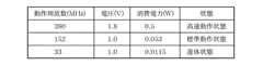
図3は、PowerPC405LPのスペックを示したものである。
また、ここでは、本装置は以下の2つの実行モードを備えているものとする。両モードは先に示した演算能力の定義(装置の演算能力=「演算器1台当たりの動作周波数」×「演算器数」)により同等の演算能力を備えている。Next, the mode change point of the execution mode
In the first embodiment, a case will be described in which a parallel computing device including 120 PowerPC (registered trademark) 405LP is assumed as a power-saving processor (arithmetic units 1-1 to 1-n) with variable operating frequency and voltage. .
FIG. 3 shows the specifications of PowerPC405LP.
Here, it is assumed that the present apparatus has the following two execution modes. Both modes have equivalent computing power according to the definition of computing power shown above (the computing capacity of the device = “operating frequency per computing unit” × “number of computing units”).
・実行モード1:プロセッサ数:120
動作周波数:152MHz(標準動作状態)
・実行モード2:プロセッサ数:48(=120×(152/380))
動作周波数:380MHz(高速動作状態)
ここで、各パラメータが以下の場合のケースを考える。
観測周期時間(単位時間)(t)=10秒
タスク数(N)=0〜400程度
演算器標準動作状態での1タスクの処理時間=2秒(高速動作状態では0.8秒)
尚、両モードともタスクを処理していない時の消費電力は0.0115W(遊休状態時)とする。-Execution mode 1: Number of processors: 120
Operating frequency: 152 MHz (standard operating condition)
Execution mode 2: Number of processors: 48 (= 120 × (152/380))
Operating frequency: 380 MHz (high speed operating state)
Here, consider the case where each parameter is as follows.
Observation cycle time (unit time) (t) = 10 seconds Number of tasks (N) = about 0 to 400 Processing time of one task in the standard operation state of the computing unit = 2 seconds (0.8 seconds in the high-speed operation state)
In both modes, the power consumption when a task is not processed is 0.0115 W (in an idle state).
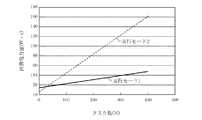
図4は、これらの値を元に、処理するタスク数に応じた単位時間(t=10秒)分の全装置の消費電力量(W・s)を求めたものを示す。この結果(図4)から、PowerPC405LPを用いた場合では、モード転換点はタスク数が25の点であり、タスク数が25程度までであれば実行モード2の方が少ない消費電力量で実行できることが分かる。 FIG. 4 shows the power consumption (W · s) of all devices for a unit time (t = 10 seconds) corresponding to the number of tasks to be processed based on these values. From this result (FIG. 4), when PowerPC405LP is used, the mode change point is the point where the number of tasks is 25, and if the number of tasks is up to about 25,
また、図5は、タスク数が25までの、実行モード1に対する実行モード2の消費電力量の比率を示したものである。この結果から、タスクを処理していない時(タスク数=0)は、実行モード2は実行モード1の40%の消費電力量で済むことになる。ここでの実施の形態のポイントは、タスク数が少ない時ほど、動作周波数を上げて実行するモードの方が少ない消費電力量で済むことである。 FIG. 5 shows the ratio of the power consumption amount in the
次に、実施の形態1の動作について説明する。
例えば、レーダシステムの場合、対象物の座標に関する値が所定の観測周期で取得される。ここで、複数の対象物のうち、一つの対象物に関する座標計算といった処理を一つのタスクとした場合、各タスクはほぼ同じであり、また、観測周期毎に発生するタスクの内容もほぼ同じである。一方、対象物の個数は時間と共に変動する。即ち、個々のタスクの内容は一定であるが、タスクの個数は変動する。このようなシステムに対して実施の形態1では次のように動作する。Next, the operation of the first embodiment will be described.
For example, in the case of a radar system, a value related to the coordinates of an object is acquired at a predetermined observation period. Here, when processing such as coordinate calculation for one object among a plurality of objects is regarded as one task, each task is almost the same, and the contents of the task that occurs at each observation period are also almost the same. is there. On the other hand, the number of objects varies with time. That is, the content of each task is constant, but the number of tasks varies. In such a system, the first embodiment operates as follows.
図6は、実施の形態1の動作を示すフローチャートである。
制御部3は、タスク群の入力待ちを行い(ステップST1)、タスク群の入力があった場合は、実行モード情報格納部2よりモード転換点TPの値を取得する(ステップST2)。次に、取得したモード転換点TPとタスク群の値(タスク数)Nとを比較し(ステップST3)、N<TPであれば実行モード1により演算器1−1〜1−nの制御を実行し(ステップST4)、N≧TPであれば実行モード2により実行する(ステップST5)。その後は、ステップST1に戻り、上記の処理を、タスク群の入力周期で同様に行う。尚、2度目以降の処理では、ステップST2で取得したモード転換点TPの値を保持しておき、これを用いるようにしてもよい。FIG. 6 is a flowchart showing the operation of the first embodiment.
The control unit 3 waits for input of the task group (step ST1), and when there is an input of the task group, acquires the value of the mode change point TP from the execution mode information storage unit 2 (step ST2). Next, the acquired mode turning point TP is compared with the value (number of tasks) N of the task group (step ST3). If N <TP, the
尚、上記実施の形態では、実行モード情報格納部2にモード転換点TPの値を保持し、タスク数とモード転換点TPとの比較により、モード選定を行うようにしたが、実行モード情報格納部2に、タスク数に対する実行モード毎の消費電力量の値を保持するようにし、制御部3は、その時点のタスク個数に応じた実行モード別の消費電力量の比較によりいずれかのモードを選択するようにしてもよい。 In the above embodiment, the mode selection point TP is held in the execution mode
以上のように、実施の形態1の並列計算装置によれば、その個数が処理タイミングによって変動し、かつ、それぞれの処理時間が一定のタスクを処理する、少なくとも1台以上の演算器1−1〜1−nと、処理能力を一定とした場合の演算器1−1〜1−nの台数と動作周波数の組み合わせからなる複数の実行モードの、使用する演算器1−1〜1−nの最も消費電力量が少ない実行モードが転換するタスクの個数を示すモード転換点の値を格納する実行モード情報格納部2と、タスクの個数が与えられた場合、実行モード情報格納部2のモード転換点と比較して使用する演算器1−1〜1−nの最も消費電力量が少ない実行モードを選択する制御部3とを備えたので、全体のタスク処理に影響を及ぼすことなく、並列計算装置としての消費電力量を低減することができる。As described above, according to the parallel computing device of the first embodiment, at least one arithmetic unit 1-1 that processes a task whose number varies depending on the processing timing and whose processing time is constant. Ofthe computing units 1-1 to 1-n to be used in a plurality of execution modes consisting of a combination of the number of computing units 1-1 to 1-n and the operating frequency when the processing capacity is constant. The execution mode
また、実施の形態1の並列計算装置によれば、処理能力を一定とした場合の演算器1−1〜1−nの台数と動作周波数の組み合わせからなる複数の実行モード毎の、タスクの個数に対する使用する演算器の消費電力量の値を格納する実行モード情報格納部2を備え、制御部3は、タスクの個数が与えられた場合、実行モード情報格納部2の実行モード毎の消費電力量の値に基づき、タスクの個数における消費電力量が最小の実行モードを選択するようにしたので、実行モードにおける演算器の台数や動作周波数の組み合わせ内容を変えた場合、あるいは実行モードを追加した場合等、実行モードの変更にも柔軟に対応することができる効果がある。 Further, according to the parallel computing device of the first embodiment, the number of tasks for each of a plurality of execution modes composed of combinations of the number of computing units 1-1 to 1-n and the operating frequency when the processing capacity is constant. The execution mode
実施の形態2.
実施の形態2は、タスクの内容の変化を考慮して実行モードを選択するようにした並列計算装置を示す例である。
図7は、実施の形態2における並列計算装置の構成図である。
図示の並列計算装置は、演算器1−1〜1−n、実行モード情報格納部2a、制御部3a、バス4、タスク情報格納部5からなる。ここで、演算器1−1〜1−nおよびバス4は、実施の形態1の演算器1−1〜1−nおよびバス4と同様である。また、実行モード情報格納部2aは、処理能力を一定とした場合の、演算器の台数と動作周波数の組み合わせからなる複数の実行モードの情報のみを格納する機能部である。タスク情報格納部5は、対象となるタスクに対する、演算器1−1〜1−nのタスク処理時間を示すタスク情報を格納する機能部である。制御部3aは、対象となるタスクとタスクの個数が与えられた場合、タスク情報格納部5におけるタスク情報と、実行モード情報格納部2aにおける実行モード情報とに基づいて、タスクの個数における実行モード毎の消費電力量を算出して、これらの値が小さいモードを実行モードとして選択する機能を有している。
The second embodiment is an example showing a parallel computing device that selects an execution mode in consideration of a change in task contents.
FIG. 7 is a configuration diagram of the parallel computing device according to the second embodiment.
The illustrated parallel computing device includes computing units 1-1 to 1-n, an execution mode
次に、実施の形態2の動作について説明する。
例えば、レーダシステムの場合、対象物に関する値として座標以外にも処理対象とする値が存在する場合がある。即ち、一つのタスクを構成する要素が運用条件等によって異なる場合がある。また、レーダシステム以外でも、処理を行うアプリケーションが異なると、そのタスク実行時間も異なる場合がある。実施の形態2では、このようなタスクに関する情報として、例えば、演算器1−1〜1−nにおける標準状態の動作周波数のタスク処理時間の情報がタスク情報格納部5に格納されている。Next, the operation of the second embodiment will be described.
For example, in the case of a radar system, there may be a value to be processed other than coordinates as a value related to an object. That is, the elements constituting one task may differ depending on the operating conditions. In addition to the radar system, the task execution time may be different if the processing application is different. In the second embodiment, for example, information on the task processing time of the operating frequency in the standard state in the computing units 1-1 to 1-n is stored in the task
図8は、実施の形態2の動作を示すフローチャートである。
制御部3aは、タスク群の入力待ちを行い(ステップST11)、タスク群の入力があった場合は、そのタスクの種類に基づき、タスク情報格納部5よりタスク情報を取得する(ステップST12)。即ち、対象となるタスクの標準状態の動作周波数のタスク処理時間の情報を取得する。次に、実行モード情報格納部2aより、実行モード情報を取得し(ステップST13)、タスク処理時間と、演算器1−1〜1−nの台数と、動作周波数に基づいて、対象となるタスクの個数に対する各モードの消費電力量の値を算出する(ステップST14)。尚、動作周波数が実行モード1の2倍である実行モード2では、処理時間を1/2として演算を行う。また、演算器1−1〜1−nへの供給電圧は一定とする。このようにして算出した実行モード1と実行モード2の消費電力量を比較し(ステップST15)、実行モード1<実行モード2であった場合は、実行モード1により実行し(ステップST16)、実行モード1≧実行モード2であった場合は、実行モード2で実行する(ステップST17)。そして、このような処理を、タスク群が入力される度に繰り返す。FIG. 8 is a flowchart showing the operation of the second embodiment.
The control unit 3a waits for an input of a task group (step ST11), and when there is an input of a task group, acquires the task information from the task
また、ステップST14で求めた各モードの消費電力量の値を蓄積し、入力されるタスク群の個数が既に求めたタスク個数であった場合は、この蓄積した値によりモード判定を行うようにしてもよい。 Also, the power consumption value of each mode obtained in step ST14 is accumulated, and if the number of input task groups is the number of tasks already obtained, mode determination is performed based on the accumulated value. Also good.
尚、上記実施の形態2において、タスクを構成する要素の増減による消費電力量の変化が、増減前の値に対する単なる加減演算で求められる場合、予め基準の値を用意しておき、増減要素の消費電力量を加減演算してモード毎の消費電力量を求め、これらを比較するようにしてもよい。即ち、タスクの要素が増減しても、図4における各モードの直線の傾きは変化しない場合、図4に示すような各モードの値を予めデータベースとして用意しておき、この値に増減要素の消費電力量の増減分を加算して判定するようにしてもよい。 In the second embodiment, when the change in power consumption due to the increase / decrease in the elements constituting the task is obtained by simple addition / subtraction with respect to the value before increase / decrease, a reference value is prepared in advance. The power consumption amount may be calculated for each mode by calculating the power consumption amount, and these may be compared. That is, if the slope of the straight line of each mode in FIG. 4 does not change even if the task element increases or decreases, the value of each mode as shown in FIG. You may make it determine by adding the increase / decrease in power consumption.
以上のように、実施の形態2の並列計算装置によれば、処理能力を一定とした場合の演算器の台数と動作周波数の組み合わせからなる複数の実行モードの情報を格納する実行モード情報格納部2aと、対象となるタスクに対する、演算器のタスク処理時間を示すタスク情報を格納するタスク情報格納部5とを備え、制御部3aは、対象となるタスクとタスクの個数が与えられた場合、タスク情報と実行モード情報とに基づいて、タスクの個数における実行モード毎の消費電力量を算出して、これらの値が小さいモードを実行モードとして選択するようにしたので、実施の形態1の効果に加えて、種々のタスクに対応することができる効果がある。 As described above, according to the parallel computing device of the second embodiment, an execution mode information storage unit that stores information on a plurality of execution modes composed of combinations of the number of operation units and the operating frequency when the processing capacity is constant. 2a and a task
尚、上記実施の形態1、2では、特に言及しなかったが、制御部3(3a)が、演算器1−1〜1−nの動作周波数を下げるよう制御する場合、演算器1−1〜1−nへの供給電圧を下げるよう制御してもよい。このようにすることにより、更に消費電力を小さくすることができる。また、電圧可変の演算器を用いた場合、演算器の台数と動作周波数を一定としたまま、供給電圧を低下させて消費電力を下げるよう制御してもよく、このような構成によっても消費電力量の低減化を図ることができる。 Although not particularly mentioned in the first and second embodiments, when the control unit 3 (3a) controls to reduce the operating frequency of the computing units 1-1 to 1-n, the computing unit 1-1. Control may be performed to reduce the supply voltage to ˜1-n. By doing so, power consumption can be further reduced. In addition, when a voltage-variable computing unit is used, it may be controlled to reduce the power consumption by reducing the supply voltage while keeping the number of computing units and the operating frequency constant. The amount can be reduced.
また、上記実施の形態1、2では、演算器1−1〜1−nは、プロセッサを主体として説明したが、これら演算器1−1〜1−nとして、プロセッサやメモリがバスを介して接続されている回路基板といった構成を対象としてもよい。更に、このような構成の場合、プロセッサの処理能力だけでなく、メモリ容量やバス性能を考慮して実行モードの選択を行うようにしてもよい。 In the first and second embodiments, the arithmetic units 1-1 to 1-n have been described mainly using processors, but as these arithmetic units 1-1 to 1-n, a processor and a memory are connected via a bus. A configuration such as a connected circuit board may be used. Further, in such a configuration, the execution mode may be selected in consideration of not only the processing capacity of the processor but also the memory capacity and bus performance.
更に、本発明の構成として、演算器1−1〜1−nをパーソナルコンピュータ等の演算装置とし、制御部3(3a)を管理用の演算装置で構成し、これらをネットワークで接続した構成であっても同様に適用可能である。即ち、この構成の場合、演算器1−1〜1−nがコンピュータ、制御部3(3a)がこれら以外のコンピュータまたはそのうちの1台のコンピュータ、バス4がネットワークに相当する。 Furthermore, as a configuration of the present invention, the computing units 1-1 to 1-n are computing devices such as a personal computer, the control unit 3 (3a) is constructed by a management computing device, and these are connected by a network. Even if it exists, it is applicable similarly. That is, in this configuration, the computing units 1-1 to 1-n correspond to computers, the control unit 3 (3a) corresponds to a computer other than these or one of them, and the bus 4 corresponds to a network.
また、以上の説明では、各演算器1−1〜1−nの処理能力は同様であるとして説明したが、演算器1−1〜1−nのそれぞれの処理能力が異なるものであってもよい。尚、このような場合は、実行モード情報として、演算器1−1〜1−n全体の処理能力が一定となるよう、使用する演算器の台数と動作周波数に加えてその演算器を特定するための情報を含むようにする。このようにすることにより、演算器の処理能力が異なる並列計算装置であっても、消費電力量の低減化を図ることができる。 In the above description, the processing units 1-1 to 1-n have been described as having the same processing capability. However, the processing units 1-1 to 1-n may have different processing capabilities. Good. In such a case, as the execution mode information, the arithmetic unit is specified in addition to the number of arithmetic units to be used and the operating frequency so that the entire processing capability of the arithmetic units 1-1 to 1-n is constant. To include information for. By doing in this way, even if it is a parallel computing device from which the processing capacity of an arithmetic unit differs, reduction of power consumption can be aimed at.
更に、このような演算器1−1〜1−nのそれぞれの処理能力が異なる構成において、制御部3(3a)は、消費電力量が同一であった場合、演算器の台数または動作周波数のいずれかを優先して実行モードを選択するようにしてもよい。このようにすれば、例えば、できるだけ演算器の台数を少なくした構成や、動作周波数を抑えた構成といった種々の構成の並列計算装置を実現することができる。 Further, in such a configuration in which the processing capabilities of each of the computing units 1-1 to 1-n are different, the control unit 3 (3a) determines the number of computing units or the operating frequency when the power consumption is the same. Either may be prioritized and the execution mode may be selected. In this way, for example, parallel computing devices having various configurations such as a configuration in which the number of arithmetic units is reduced as much as possible and a configuration in which the operating frequency is suppressed can be realized.
また、上記各実施の形態では、本発明をレーダシステムに適用した例を説明したが、これに限定されるものではなく、例えば、電話交換システムにおけるそれぞれの呼処理(=タスク)といった、複数の演算器を用いて、タスクの個数が処理タイミングによって変動し、かつ、それぞれの処理時間が一定のタスクを処理するようなシステムであれば同様に適用可能である。 In each of the above embodiments, the example in which the present invention is applied to the radar system has been described. However, the present invention is not limited to this. For example, a plurality of call processes (= tasks) in a telephone exchange system, The present invention can be similarly applied to a system that uses an arithmetic unit to process a task in which the number of tasks varies depending on the processing timing and each processing time is constant.
1−1〜1−n 演算器、2,2a 実行モード情報格納部、3,3a 制御部、5 タスク情報格納部。 1-1 to 1-n computing units, 2, 2a execution mode information storage unit, 3, 3a control unit, 5 task information storage unit.
Claims (6)
Translated fromJapanese処理能力を一定とした場合の前記演算器の台数と動作周波数の組み合わせからなる複数の実行モードの、使用する演算器の最も消費電力量が少ない実行モードが転換するタスクの個数を示すモード転換点の値を格納する実行モード情報格納部と、
タスクの個数が与えられた場合、前記実行モード情報格納部のモード転換点と比較して使用する演算器の最も消費電力量が少ない実行モードを選択する制御部とを備えた並列計算装置。At least one arithmetic unit that processes a task whose number varies depending on the processing timing and each processing time is constant;
A mode turning point that indicates the number of tasks to which the execution mode with the least amount of power consumption of the computing unit to be used is switched among a plurality of execution modes consisting of a combination of the number of computing units and the operating frequency when the processing capacity is constant. An execution mode information storage for storing the value of
A parallel computing device comprising: a control unit that selects anexecution mode with theleast amount of power consumption of an arithmetic unit to be used in comparison with a mode switching point of the execution mode information storage unit when the number of tasks is given .
処理能力を一定とした場合の演算器の台数と動作周波数の組み合わせからなる複数の実行モード毎の、タスクの個数に対する使用する演算器の消費電力量の値を格納する実行モード情報格納部と、
タスクの個数が与えられた場合、前記実行モード情報格納部の実行モード毎の消費電力量の値に基づき、当該タスクの個数における消費電力量が最小の実行モードを選択する制御部とを備えた並列計算装置。At least one arithmetic unit that processes a task whose number varies depending on the processing timing and each processing time is constant;
A plurality of execution modes each consisting of a combination of the number and the operating frequency of the arithmetic unit in the case where the processing power is constant,and the execution mode information storing unit for storing the value of the power consumption calculator for use to the number of tasks,
When the number of tasks is given, thecontroller includes a control unit that selects an execution mode with the minimum power consumption for the number of tasks based on the value of the power consumption for each execution mode of the execution mode information storage unit Parallel computing device.
処理能力を一定とした場合の演算器の台数と動作周波数の組み合わせからなる複数の実行モードの情報を格納する実行モード情報格納部と、
対象となるタスクに対する、前記演算器のタスク処理時間を示すタスク情報を格納するタスク情報格納部と、
対象となるタスクと当該タスクの個数が与えられた場合、前記タスク情報と前記実行モード情報とに基づいて、前記タスクの個数における実行モード毎の消費電力量を算出して、これらの値が小さいモードを実行モードとして選択する制御部とを備えた並列計算装置。At least one arithmetic unit that processes a task whose number varies depending on the processing timing and each processing time is constant;
An execution mode information storage unit that stores information on a plurality of execution modes consisting of combinations of the number of operation units and the operating frequency when the processing capacity is constant;
A task information storage unit for storing task information indicating a task processing time of the computing unit for a target task;
When the target task and the number of tasks are given, the power consumption for each execution mode in the number of tasks is calculated based on the task information and the execution mode information, and these values are small.A parallel computing devicecomprising acontrol unit that selects a mode as an execution mode.
Priority Applications (1)
| Application Number | Priority Date | Filing Date | Title |
|---|---|---|---|
| JP2005001710AJP4485370B2 (en) | 2005-01-06 | 2005-01-06 | Parallel computing device |
Applications Claiming Priority (1)
| Application Number | Priority Date | Filing Date | Title |
|---|---|---|---|
| JP2005001710AJP4485370B2 (en) | 2005-01-06 | 2005-01-06 | Parallel computing device |
Publications (2)
| Publication Number | Publication Date |
|---|---|
| JP2006190104A JP2006190104A (en) | 2006-07-20 |
| JP4485370B2true JP4485370B2 (en) | 2010-06-23 |
Family
ID=36797248
Family Applications (1)
| Application Number | Title | Priority Date | Filing Date |
|---|---|---|---|
| JP2005001710AExpired - Fee RelatedJP4485370B2 (en) | 2005-01-06 | 2005-01-06 | Parallel computing device |
Country Status (1)
| Country | Link |
|---|---|
| JP (1) | JP4485370B2 (en) |
Families Citing this family (8)
| Publication number | Priority date | Publication date | Assignee | Title |
|---|---|---|---|---|
| JP5011028B2 (en)* | 2007-08-23 | 2012-08-29 | 株式会社日立製作所 | Storage system, management apparatus, scheduling method, program, recording medium |
| KR20110007205A (en) | 2008-04-21 | 2011-01-21 | 어댑티브 컴퓨팅 엔터프라이즈 인코포레이티드 | Systems and Methods for Managing Energy Consumption in Compute Environments |
| US9405348B2 (en) | 2008-04-21 | 2016-08-02 | Adaptive Computing Enterprises, Inc | System and method for managing energy consumption in a compute environment |
| JP5238525B2 (en)* | 2009-01-13 | 2013-07-17 | 株式会社東芝 | Device and program for managing resources |
| JP2010277350A (en)* | 2009-05-28 | 2010-12-09 | Toshiba Corp | Electronics |
| JP5070609B2 (en)* | 2010-05-07 | 2012-11-14 | Necシステムテクノロジー株式会社 | COMMUNICATION DEVICE, COMMUNICATION SYSTEM, AND COMMUNICATION METHOD |
| JP6196886B2 (en)* | 2013-11-15 | 2017-09-13 | オリンパス株式会社 | Arithmetic unit |
| CN119828140A (en)* | 2024-12-30 | 2025-04-15 | 西安电子科技大学 | Multistage parallel processing system for ultra-large data volume of SAR (synthetic aperture radar) of middle and high rail |
Family Cites Families (5)
| Publication number | Priority date | Publication date | Assignee | Title |
|---|---|---|---|---|
| JPH09185589A (en)* | 1996-01-05 | 1997-07-15 | Toshiba Corp | Information processing system and power saving method for information processing system |
| US6141762A (en)* | 1998-08-03 | 2000-10-31 | Nicol; Christopher J. | Power reduction in a multiprocessor digital signal processor based on processor load |
| JP3645135B2 (en)* | 1999-09-30 | 2005-05-11 | 三菱電機株式会社 | Parallel multi-target tracking device |
| JP2002099433A (en)* | 2000-09-22 | 2002-04-05 | Sony Corp | System of computing processing, control method system for task control, method therefor and record medium |
| JP3713015B2 (en)* | 2002-12-16 | 2005-11-02 | 三菱電機株式会社 | Radar signal processing apparatus and radar signal processing method |
- 2005
- 2005-01-06JPJP2005001710Apatent/JP4485370B2/ennot_activeExpired - Fee Related
Also Published As
| Publication number | Publication date |
|---|---|
| JP2006190104A (en) | 2006-07-20 |
Similar Documents
| Publication | Publication Date | Title |
|---|---|---|
| US10983576B2 (en) | Method and apparatus for managing global chip power on a multicore system on chip | |
| US8694811B2 (en) | Power management for digital devices | |
| US6889332B2 (en) | Variable maximum die temperature based on performance state | |
| JP4808108B2 (en) | Processor system | |
| US10372494B2 (en) | Thread importance based processor core partitioning | |
| US10528119B2 (en) | Dynamic power routing to hardware accelerators | |
| US8122269B2 (en) | Regulating power consumption in a multi-core processor by dynamically distributing power and processing requests by a managing core to a configuration of processing cores | |
| US10234919B2 (en) | Accessory-based power distribution | |
| JP2020505703A (en) | Adaptive power control loop | |
| EP1785804A2 (en) | Computer docking system and method | |
| CN110795238B (en) | Load calculation method, device, storage medium and electronic equipment | |
| WO2014148174A1 (en) | Electronic device | |
| WO2017184347A1 (en) | Adaptive doze to hibernate | |
| CN101467117B (en) | Save power in circuit functions through multiple power buses | |
| US20130080809A1 (en) | Server system and power managing method thereof | |
| US20190146567A1 (en) | Processor throttling based on accumulated combined current measurements | |
| JP2009193385A (en) | Computer system | |
| JP4485370B2 (en) | Parallel computing device | |
| US10539995B2 (en) | Performance boosting method and system of semiconductor device | |
| US20150220362A1 (en) | Multi-core processor system, electrical power control method, and computer product for migrating process from one core to another | |
| KR101510694B1 (en) | Apparatus and method for processing data | |
| EP2798437A1 (en) | Middleware power management | |
| KR20200101210A (en) | Electronic device and method for determining operating frequency of processor | |
| CN116610204B (en) | Power management method, system, electronic equipment and medium for electric equipment | |
| CN119536493A (en) | A control method and electronic device |
Legal Events
| Date | Code | Title | Description |
|---|---|---|---|
| A621 | Written request for application examination | Free format text:JAPANESE INTERMEDIATE CODE: A621 Effective date:20070921 | |
| RD04 | Notification of resignation of power of attorney | Free format text:JAPANESE INTERMEDIATE CODE: A7424 Effective date:20071003 | |
| RD04 | Notification of resignation of power of attorney | Free format text:JAPANESE INTERMEDIATE CODE: A7424 Effective date:20080722 | |
| A977 | Report on retrieval | Free format text:JAPANESE INTERMEDIATE CODE: A971007 Effective date:20090708 | |
| A131 | Notification of reasons for refusal | Free format text:JAPANESE INTERMEDIATE CODE: A131 Effective date:20090714 | |
| A521 | Request for written amendment filed | Free format text:JAPANESE INTERMEDIATE CODE: A523 Effective date:20090901 | |
| A131 | Notification of reasons for refusal | Free format text:JAPANESE INTERMEDIATE CODE: A131 Effective date:20091027 | |
| A521 | Request for written amendment filed | Free format text:JAPANESE INTERMEDIATE CODE: A523 Effective date:20091217 | |
| TRDD | Decision of grant or rejection written | ||
| A01 | Written decision to grant a patent or to grant a registration (utility model) | Free format text:JAPANESE INTERMEDIATE CODE: A01 Effective date:20100316 | |
| A01 | Written decision to grant a patent or to grant a registration (utility model) | Free format text:JAPANESE INTERMEDIATE CODE: A01 | |
| A61 | First payment of annual fees (during grant procedure) | Free format text:JAPANESE INTERMEDIATE CODE: A61 Effective date:20100324 | |
| R150 | Certificate of patent or registration of utility model | Ref document number:4485370 Country of ref document:JP Free format text:JAPANESE INTERMEDIATE CODE: R150 Free format text:JAPANESE INTERMEDIATE CODE: R150 | |
| FPAY | Renewal fee payment (event date is renewal date of database) | Free format text:PAYMENT UNTIL: 20130402 Year of fee payment:3 | |
| FPAY | Renewal fee payment (event date is renewal date of database) | Free format text:PAYMENT UNTIL: 20130402 Year of fee payment:3 | |
| FPAY | Renewal fee payment (event date is renewal date of database) | Free format text:PAYMENT UNTIL: 20140402 Year of fee payment:4 | |
| R250 | Receipt of annual fees | Free format text:JAPANESE INTERMEDIATE CODE: R250 | |
| R250 | Receipt of annual fees | Free format text:JAPANESE INTERMEDIATE CODE: R250 | |
| R250 | Receipt of annual fees | Free format text:JAPANESE INTERMEDIATE CODE: R250 | |
| R250 | Receipt of annual fees | Free format text:JAPANESE INTERMEDIATE CODE: R250 | |
| R250 | Receipt of annual fees | Free format text:JAPANESE INTERMEDIATE CODE: R250 | |
| R250 | Receipt of annual fees | Free format text:JAPANESE INTERMEDIATE CODE: R250 | |
| R250 | Receipt of annual fees | Free format text:JAPANESE INTERMEDIATE CODE: R250 | |
| R250 | Receipt of annual fees | Free format text:JAPANESE INTERMEDIATE CODE: R250 | |
| LAPS | Cancellation because of no payment of annual fees |