JP4485197B2 - Flooring - Google Patents
FlooringDownload PDFInfo
- Publication number
- JP4485197B2 JP4485197B2JP2003528920AJP2003528920AJP4485197B2JP 4485197 B2JP4485197 B2JP 4485197B2JP 2003528920 AJP2003528920 AJP 2003528920AJP 2003528920 AJP2003528920 AJP 2003528920AJP 4485197 B2JP4485197 B2JP 4485197B2
- Authority
- JP
- Japan
- Prior art keywords
- floorboard
- connecting means
- flooring
- floor
- locking
- Prior art date
- Legal status (The legal status is an assumption and is not a legal conclusion. Google has not performed a legal analysis and makes no representation as to the accuracy of the status listed.)
- Expired - Lifetime
Links
- 238000009408flooringMethods0.000titleclaimsabstractdescription36
- 238000005304joiningMethods0.000claimsdescription63
- 210000002105tongueAnatomy0.000claimsdescription50
- 239000002023woodSubstances0.000claimsdescription22
- 239000000853adhesiveSubstances0.000claimsdescription15
- 230000001070adhesive effectEffects0.000claimsdescription15
- 230000008878couplingEffects0.000claimsdescription7
- 238000010168coupling processMethods0.000claimsdescription7
- 238000005859coupling reactionMethods0.000claimsdescription7
- 238000007667floatingMethods0.000claimsdescription7
- 239000002344surface layerSubstances0.000claimsdescription6
- 238000000034methodMethods0.000description50
- 238000004519manufacturing processMethods0.000description24
- 238000009434installationMethods0.000description20
- 238000003754machiningMethods0.000description17
- 239000000463materialSubstances0.000description17
- 238000003780insertionMethods0.000description12
- 230000037431insertionEffects0.000description12
- 238000005520cutting processMethods0.000description7
- 239000010410layerSubstances0.000description5
- 239000004033plasticSubstances0.000description5
- 229920002522Wood fibrePolymers0.000description4
- 239000011162core materialSubstances0.000description4
- 229910003460diamondInorganic materials0.000description4
- 239000010432diamondSubstances0.000description4
- 238000006073displacement reactionMethods0.000description4
- 239000002025wood fiberSubstances0.000description4
- 241000218645CedrusSpecies0.000description3
- 229910052782aluminiumInorganic materials0.000description3
- XAGFODPZIPBFFR-UHFFFAOYSA-NaluminiumChemical compound[Al]XAGFODPZIPBFFR-UHFFFAOYSA-N0.000description3
- 238000012986modificationMethods0.000description3
- 230000004048modificationEffects0.000description3
- 229920002994synthetic fiberPolymers0.000description3
- 241000712281Guapira fragransSpecies0.000description2
- 239000007799corkSubstances0.000description2
- 238000013461designMethods0.000description2
- 238000010586diagramMethods0.000description2
- 239000011094fiberboardSubstances0.000description2
- 239000000123paperSubstances0.000description2
- 238000004026adhesive bondingMethods0.000description1
- 239000003795chemical substances by applicationSubstances0.000description1
- 238000010276constructionMethods0.000description1
- 238000007796conventional methodMethods0.000description1
- 238000000354decomposition reactionMethods0.000description1
- 230000001419dependent effectEffects0.000description1
- 230000000694effectsEffects0.000description1
- 239000000835fiberSubstances0.000description1
- 239000006260foamSubstances0.000description1
- 238000005470impregnationMethods0.000description1
- 238000003475laminationMethods0.000description1
- -1linoleumSubstances0.000description1
- 229910052751metalInorganic materials0.000description1
- 239000002184metalSubstances0.000description1
- 238000003825pressingMethods0.000description1
- 239000012209synthetic fiberSubstances0.000description1
- 239000002966varnishSubstances0.000description1
Images


Classifications
- E—FIXED CONSTRUCTIONS
- E04—BUILDING
- E04F—FINISHING WORK ON BUILDINGS, e.g. STAIRS, FLOORS
- E04F15/00—Flooring
- E04F15/02—Flooring or floor layers composed of a number of similar elements
- E—FIXED CONSTRUCTIONS
- E04—BUILDING
- E04C—STRUCTURAL ELEMENTS; BUILDING MATERIALS
- E04C2/00—Building elements of relatively thin form for the construction of parts of buildings, e.g. sheet materials, slabs, or panels
- E04C2/02—Building elements of relatively thin form for the construction of parts of buildings, e.g. sheet materials, slabs, or panels characterised by specified materials
- E04C2/10—Building elements of relatively thin form for the construction of parts of buildings, e.g. sheet materials, slabs, or panels characterised by specified materials of wood, fibres, chips, vegetable stems, or the like; of plastics; of foamed products
- E04C2/20—Building elements of relatively thin form for the construction of parts of buildings, e.g. sheet materials, slabs, or panels characterised by specified materials of wood, fibres, chips, vegetable stems, or the like; of plastics; of foamed products of plastics
- E—FIXED CONSTRUCTIONS
- E04—BUILDING
- E04F—FINISHING WORK ON BUILDINGS, e.g. STAIRS, FLOORS
- E04F15/00—Flooring
- E04F15/02—Flooring or floor layers composed of a number of similar elements
- E04F15/02005—Construction of joints, e.g. dividing strips
- E04F15/02033—Joints with beveled or recessed upper edges
- E—FIXED CONSTRUCTIONS
- E04—BUILDING
- E04F—FINISHING WORK ON BUILDINGS, e.g. STAIRS, FLOORS
- E04F15/00—Flooring
- E04F15/02—Flooring or floor layers composed of a number of similar elements
- E04F15/04—Flooring or floor layers composed of a number of similar elements only of wood or with a top layer of wood, e.g. with wooden or metal connecting members
- E—FIXED CONSTRUCTIONS
- E04—BUILDING
- E04F—FINISHING WORK ON BUILDINGS, e.g. STAIRS, FLOORS
- E04F2201/00—Joining sheets or plates or panels
- E04F2201/01—Joining sheets, plates or panels with edges in abutting relationship
- E04F2201/0107—Joining sheets, plates or panels with edges in abutting relationship by moving the sheets, plates or panels substantially in their own plane, perpendicular to the abutting edges
- E04F2201/0115—Joining sheets, plates or panels with edges in abutting relationship by moving the sheets, plates or panels substantially in their own plane, perpendicular to the abutting edges with snap action of the edge connectors
- E—FIXED CONSTRUCTIONS
- E04—BUILDING
- E04F—FINISHING WORK ON BUILDINGS, e.g. STAIRS, FLOORS
- E04F2201/00—Joining sheets or plates or panels
- E04F2201/01—Joining sheets, plates or panels with edges in abutting relationship
- E04F2201/0153—Joining sheets, plates or panels with edges in abutting relationship by rotating the sheets, plates or panels around an axis which is parallel to the abutting edges, possibly combined with a sliding movement
- E—FIXED CONSTRUCTIONS
- E04—BUILDING
- E04F—FINISHING WORK ON BUILDINGS, e.g. STAIRS, FLOORS
- E04F2201/00—Joining sheets or plates or panels
- E04F2201/02—Non-undercut connections, e.g. tongue and groove connections
- E04F2201/023—Non-undercut connections, e.g. tongue and groove connections with a continuous tongue or groove
- E—FIXED CONSTRUCTIONS
- E04—BUILDING
- E04F—FINISHING WORK ON BUILDINGS, e.g. STAIRS, FLOORS
- E04F2201/00—Joining sheets or plates or panels
- E04F2201/02—Non-undercut connections, e.g. tongue and groove connections
- E04F2201/026—Non-undercut connections, e.g. tongue and groove connections with rabbets, e.g. being stepped
- E—FIXED CONSTRUCTIONS
- E04—BUILDING
- E04F—FINISHING WORK ON BUILDINGS, e.g. STAIRS, FLOORS
- E04F2201/00—Joining sheets or plates or panels
- E04F2201/02—Non-undercut connections, e.g. tongue and groove connections
- E04F2201/027—Non-undercut connections, e.g. tongue and groove connections connected by tongues and grooves, the centerline of the connection being inclined to the top surface
- E—FIXED CONSTRUCTIONS
- E04—BUILDING
- E04F—FINISHING WORK ON BUILDINGS, e.g. STAIRS, FLOORS
- E04F2201/00—Joining sheets or plates or panels
- E04F2201/04—Other details of tongues or grooves
- E04F2201/042—Other details of tongues or grooves with grooves positioned on the rear-side of the panel
- E—FIXED CONSTRUCTIONS
- E04—BUILDING
- E04F—FINISHING WORK ON BUILDINGS, e.g. STAIRS, FLOORS
- E04F2201/00—Joining sheets or plates or panels
- E04F2201/05—Separate connectors or inserts, e.g. pegs, pins, keys or strips
- E04F2201/0517—U- or C-shaped brackets and clamps
- Y—GENERAL TAGGING OF NEW TECHNOLOGICAL DEVELOPMENTS; GENERAL TAGGING OF CROSS-SECTIONAL TECHNOLOGIES SPANNING OVER SEVERAL SECTIONS OF THE IPC; TECHNICAL SUBJECTS COVERED BY FORMER USPC CROSS-REFERENCE ART COLLECTIONS [XRACs] AND DIGESTS
- Y10—TECHNICAL SUBJECTS COVERED BY FORMER USPC
- Y10T—TECHNICAL SUBJECTS COVERED BY FORMER US CLASSIFICATION
- Y10T29/00—Metal working
- Y10T29/49—Method of mechanical manufacture
- Y—GENERAL TAGGING OF NEW TECHNOLOGICAL DEVELOPMENTS; GENERAL TAGGING OF CROSS-SECTIONAL TECHNOLOGIES SPANNING OVER SEVERAL SECTIONS OF THE IPC; TECHNICAL SUBJECTS COVERED BY FORMER USPC CROSS-REFERENCE ART COLLECTIONS [XRACs] AND DIGESTS
- Y10—TECHNICAL SUBJECTS COVERED BY FORMER USPC
- Y10T—TECHNICAL SUBJECTS COVERED BY FORMER US CLASSIFICATION
- Y10T409/00—Gear cutting, milling, or planing
- Y10T409/30—Milling
- Y10T409/303752—Process
Landscapes
- Engineering & Computer Science (AREA)
- Architecture (AREA)
- Civil Engineering (AREA)
- Structural Engineering (AREA)
- Life Sciences & Earth Sciences (AREA)
- Wood Science & Technology (AREA)
- Floor Finish (AREA)
- Noodles (AREA)
- Devices For Conveying Motion By Means Of Endless Flexible Members (AREA)
- Mechanical Treatment Of Semiconductor (AREA)
- Road Repair (AREA)
Abstract
Description
Translated fromJapanese 本発明は、全体として、フロアボード用係止システムの技術分野に関する。本発明は、請求項1に特有な部分によるフローリングに関する。本発明は、フロアボードと一体化した機械式係止システム、例えばWO94/26999、WO96/47834、WO97/27721、WO99/66151、WO99/66152、WO00/28171、スウェーデン特許第0100100−7号、及びスウェーデン特許第0100101−5号に記載されており且つ示された種類の機械式係止システムで使用するのに特に適しているが、フローリングを接合するためのこの他の接合システムでも使用できる。これらの特許に触れたことにより、これらの特許に開示された内容は本明細書中に含まれたものとする。The present invention relates generally to the technical field of floorboard locking systems. The invention relatesto a flooring according to the features specific to claim 1. The present invention relates to a mechanical locking system integrated with a floorboard, such as WO 94/26999, WO 96/47834,WO 97/27721 , WO 99/66151, WO 99/66152,
更に詳細には、本発明は、とりわけ、主にフローティングフロアを最新のパターンで敷設できる係止システムに関する。 More particularly, the present invention relates to a locking system capable of laying mainly a floating floor in a modern pattern.
本発明は、重量のある木製フロア、寄木フロア、高圧積層体又は直接積層体で形成された表面層を持つ積層体フロア等の木材又は積層体でできたフローティングフロアで使用するのに特に適している。寄木フロアは、多くの場合、木製の表面層、コア、及びバランシング層を含み、長側部及び短側部の両方に沿って接合されるようになった矩形フロアボードとして形成される。積層体フロアは、表面層及びバランシング層をHDF等の木材繊維でできたコア材料に適用することによって製造される。この適用は、現在製造されている高圧積層体の装飾層の接着によって行うことができる。この装飾層は、含浸させた複数の紙シートを高圧及び高温で互いにプレスする別の作業で製作される。しかしながら、積層体フロアを製造するための現在の最も一般的な方法は、装飾層の製造とファイバボードへの取り外しの両方を一つの同じ製造工程で行う、更に最新の原理に基づく直接積層法である。含浸させた紙シートをボードに直接適用し、高圧高温で接着剤を用いずに互いにプレスする。 The present invention is particularly suitable for use on wood or laminate floating floors such as heavy wooden floors, parquet floors, laminate floors with surface layers formed of high pressure laminates or direct laminates. Yes. Parquet floors are often formed as rectangular floorboards that include a wooden surface layer, a core, and a balancing layer and are joined along both the long and short sides. The laminate floor is manufactured by applying a surface layer and a balancing layer to a core material made of wood fibers such as HDF. This application can be made by adhering a decorative layer of a currently produced high pressure laminate. This decorative layer is produced in a separate operation in which a plurality of impregnated paper sheets are pressed together at high pressure and high temperature. However, the current most common method for producing laminate floors is a direct lamination method based on the latest principles, in which both the production of the decorative layer and the removal to the fiberboard are done in one and the same production process. is there. The impregnated paper sheets are applied directly to the board and pressed together at high pressure and high temperature without using an adhesive.
従って、従来の技術、周知のシステムの問題点、並びに本発明の目的及び特徴の以下の説明は、主にこの適用分野に絞った非限定的例である。しかしながら、本発明は、機械式接合システムによって様々なパターンで接合されるようになった随意のフロアボードで使用できるということを強調しておかなければならない。本発明は、かくして、プラスチック製、リノリウム製、コルク製、ラッカーを塗布した木材繊維表面、合成繊維、等でできた表面を持つフロアに適用できる。 Thus, the prior art, known system problems, and the following description of the objects and features of the present invention are non-limiting examples primarily focused on this field of application. However, it should be emphasized that the present invention can be used with any floorboard that has been joined in various patterns by a mechanical joining system. The present invention is thus applicable to floors having surfaces made of plastic, linoleum, cork, lacquered wood fiber surfaces, synthetic fibers, and the like.
従来の積層体フロア及び寄木フロアは、通常は、フローティング態様で、即ち接着剤を用いないで現存の下張り床に敷設され、この下張り床は、必ずしも非常に滑らかであったり平坦でなくてもよい。或る程度の凹凸は、フロアボードと下張り床との間に敷設されたコルクボード、コルク、又はフォームプラスチックの形態の下敷き材料によって無くされる。この種のフローティングフロアは、通常は、接着剤を用いたさねはぎ(即ち、一方のフロアボードに設けられたタング及び隣接したフロアボードに設けられたタング溝を使用する継手)によって長側部及び短側部で接合される。敷設にあたり、ボードを水平方向で接合し、一つのボードの接合縁部に沿った突出タングを隣接したボードの接合縁部に沿ったタング溝に挿入する。長側部及び短側部で同じ方法が使用され、これらのボードは通常は、長側部が長側部に対して平行であり且つ短側部が短側部に対して平行な状態で敷設される。 Conventional laminate floors and parquet floors are usually laid on an existing subfloor in a floating manner, i.e. without the use of an adhesive, and this subfloor may not necessarily be very smooth or flat. . Some irregularities are eliminated by the underlaying material in the form of corkboard, cork or foam plastic laid between the floorboard and the subfloor. This type of floating floor is usually long sided by glued tongues (ie, joints that use tongues on one floorboard and tongue grooves on adjacent floorboards). And joined at the short side. In laying, the boards are joined in the horizontal direction, and a protruding tongue along the joining edge of one board is inserted into a tongue groove along the joining edge of an adjacent board. The same method is used on the long and short sides, and these boards are usually laid with the long side parallel to the long side and the short side parallel to the short side. Is done.
接着剤を用いたさねはぎによって接合されるこのような従来のフロアの他に、近年、接着剤を使用する必要がなく、その代わりにいわゆる機械式接合システムによって機械的に接合するフロアが開発された。これらのシステムは、ボードを水平方向及び垂直方向で係止する係止手段を備えている。機械式接合システムは、ボードのコアを機械加工することによって形成できる。別の態様では、係止システムの部品を、フロアボードと一体化した別の材料で、即ち工場でのフロアボードの製造と関連して予め接合した材料で形成できる。フロアボードは、傾け、スナップ嵌め、及び係止位置での接合縁部に沿った挿入の様々な組み合わせによって接合され、即ち相互連結され、即ち互いに係止される。本願では、相互連結という用語は、連結手段を持つフロアボードを一つの方向で、例えば水平方向で又は垂直方向で機械的に相互連結することを意味する。しかしながら、互いに係止するという用語は、フロアボードを水平方向及び垂直方向の両方向で係止することを意味する。 In addition to these conventional floors that are joined by tongue and groove using adhesives, in recent years, there has been no need to use adhesives, but instead floors that have been mechanically joined by so-called mechanical joining systems have been developed. It was done. These systems include locking means for locking the board in the horizontal and vertical directions. A mechanical joining system can be formed by machining the core of the board. In another aspect, the components of the locking system can be formed of another material that is integrated with the floorboard, i.e., a material that has been pre-joined in connection with the manufacture of the floorboard in the factory. The floorboards are joined, i.e. interconnected, i.e. locked together, by various combinations of tilting, snap-fit and insertion along the joining edge in the locked position. In this application, the term interconnect means mechanically interconnecting floorboards with connecting means in one direction, for example in the horizontal direction or in the vertical direction. However, the term locking together means locking the floorboard in both the horizontal and vertical directions.
機械式接合システムを持つフローティングフロアの主な利点は、内方への傾け及びスナップ嵌めの様々な組み合わせで手早く且つ容易に敷設できるということである。また、再度取り外して他の場所で再使用することを容易に行うことができる。 The main advantage of a floating floor with a mechanical joining system is that it can be laid quickly and easily with various combinations of inward tilt and snap fit. Further, it can be easily removed and reused in another place.
全ての現存の機械式接合システム及び接着剤で接合されるようになったフロアは、フロアボードをボードの表面平面に亘って係止する垂直方向係止手段を有する。垂直方向係止手段はタングを含み、このタングは隣接したフロアボードの溝に進入する。ボードは、かくして、溝を溝に対して、及びタングをタングに対して接合することはできない。更に、水平方向係止システムは、概して、一方の側部に設けられた係止エレメントを含み、このエレメントは他方の側部に設けられた係止溝と協働する。かくして、ボードは、係止エレメントを係止エレメントに対して、及び係止溝を係止溝に対して接合することはできない。このことは、敷設が、実際には、平行な列に限定されるということを意味する。この技術を使用した場合、長側部を短側部に対してボードを「杉綾(herringbone)パターン」で、又は異なるダイヤモンドパターンの形態で接合する伝統的寄木パターンを敷設することができないのである。 All existing mechanical joining systems and floors adapted to be joined with adhesive have vertical locking means for locking the floorboard across the surface plane of the board. The vertical locking means includes a tongue that enters the groove of the adjacent floorboard. The board can thus not join the groove to the groove and the tongue to the tongue. In addition, the horizontal locking system generally includes a locking element provided on one side, which cooperates with a locking groove provided on the other side. Thus, the board cannot join the locking element to the locking element and the locking groove to the locking groove. This means that laying is actually limited to parallel rows. Using this technique, it is not possible to lay a traditional parquet pattern that joins the board in a “herringbone pattern”, or in the form of a different diamond pattern, with the long side on the short side.
このような高度なパターンは、元来は、適当な大きさ及び形状の多数の木材ブロックを所望のパターンに従って下張り床に接着した後、研削を施して均等な床面を形成し、例えばワニス又はオイルで仕上げることによって敷設されてきた。この技術によれば、木材ブロックは係止手段を備えていない。これは、接着剤によって下張り床に固定されるためである。 Such advanced patterns were originally created by bonding a number of appropriately sized and shaped wood blocks to an underfloor according to a desired pattern and then grinding to form a uniform floor surface, for example varnish or It has been laid by finishing with oil. According to this technique, the wood block has no locking means. This is because it is fixed to the underfloor by an adhesive.
高度なパターンを敷設する別の周知の方法は、木材ブロックの全ての縁部に沿って溝を形成することを含む。この場合、木材ブロックを敷設するとき、必要な位置でタングを溝に挿入する。これにより、二つの隣接した木材ブロックのタング溝にタングを係合することによって木材ブロックを垂直方向で互いに対して係止したフロアが形成される。随意であるが、この方法は、接着によりフロアを水平方向及び垂直方向で下張り床に対して係止することによって補助される。 Another well-known method of laying advanced patterns involves forming grooves along all edges of the wood block. In this case, when laying the wood block, the tongue is inserted into the groove at a required position. Thereby, the floor which locked the wood block with respect to each other in the vertical direction by engaging the tongue with the tongue groove of two adjacent wood blocks is formed. Optionally, this method is aided by locking the floor to the subfloor in the horizontal and vertical directions by gluing.
米国特許第1,787,027号(ワズレフ)には、杉綾寄木フロアを敷設するための別のシステムが開示されている。このシステムは、杉綾寄木フロアを形成するように下張り床に敷設した複数の木材ブロックを含む。各木材ブロックには、木材ブロックの各縁部の部分に亘って延びる一組のタング及びタング溝が設けられている。木材部分を杉綾パターンで敷設するとき、タング及びタング溝が互いに協働し、木材部分を垂直方向及び水平方向の両方向で互いに機械的に係止する。しかしながら、ワズレフに示されたタング及びタング溝は旧式であり、即ちスナップ嵌めも互いに傾けることもできず、複数の木材部分を一緒に敷設してフロアを形成する場合しか係止効果が得られない。ワズレフによるシステムは、タング及びタング溝の位置に関して互いに対して鏡像をなして逆に配置された2種類の木材ブロックを含む。係止システムは、図示のタング溝の形成にシャンク端ミルを必要とするような設計になっている。これは、シャンク端ミルを使用する機械加工が比較的緩慢な製造作業であるため、欠点である。 U.S. Pat. No. 1,787,027 (Wazlef) discloses another system for laying a cedar twilled parquet floor. The system includes a plurality of timber blocks laid on an underlaying floor so as to form a herringwood floor. Each wood block is provided with a set of tongues and tongue grooves extending across the edge portions of the wood block. When laying the timber part in a herringbone pattern, the tongues and tang grooves work together to mechanically lock the timber parts together in both the vertical and horizontal directions. However, the tongues and tongue grooves shown in the Waslev are obsolete, i.e. they cannot be snap-fitted nor tilted to each other, and only a locking effect can be obtained when laying together several wood parts to form a floor . The system according to Wazulev includes two types of wood blocks that are arranged in a mirror image relative to each other with respect to the position of the tongue and tongue groove. The locking system is designed to require a shank end mill to form the tongue groove shown. This is a disadvantage because machining using a shank end mill is a relatively slow manufacturing operation.
米国特許第4,426,820号(テルブラック)には、フロアが二つの異なるフロアボードを含む場合にフロアボードの長側部を短側部に接合できるということが開示されている。この接合システムは、単に内方への傾けによって敷設できる。係止位置では変位できず、これらのフロアボードはスナップ嵌めでは接合できない。更に、図11及び23は、互いに対して鏡像をなして逆になったフロアボードを示す。しかしながら、これは、説明で詳細には論じられていない。第5コラムの第10行目乃至第13行目には、短側部を長側部に接合できるという記載が含まれているように思える。しかしながら、パターンを形成するためにこのようなフロアボードを使用してフロア全体を接合する方法は示されていない。接合位置での変位可能であること及びスナップ嵌め可能であることが存在しなかったため、テルブラックによって開示されたこのようなフロアボードを使用して、本発明が目的とする種類のフロアを形成することはできなかった。 U.S. Pat. No. 4,426,820 (Tell Black) discloses that the long side of the floorboard can be joined to the short side when the floor includes two different floorboards. This joining system can be laid simply by inward tilting. They cannot be displaced in the locked position, and these floorboards cannot be joined with a snap fit. In addition, FIGS. 11 and 23 show floorboards that are mirror images of each other and reversed. However, this is not discussed in detail in the description. The tenth to thirteenth rows of the fifth column seem to contain a statement that the short side can be joined to the long side. However, no method is shown for joining the entire floor using such floorboards to form a pattern. Such floorboards disclosed by Tell Black have been used to form the type of floor to which the present invention is intended because there was no displaceability at the joint location and no snap fit. I couldn't.
米国特許第5,295,341号(カジワラ)には、二つの異なる長側部を持つスナップ嵌め可能なフロアボードが開示されている。長側部の一方の部分には溝部分が形成されており、別の部分にはタング部分が形成されている。このようなフロアのいずれも係止位置で変位できない。製造が複雑であり、しかも所望のパターンを提供するのに使用できない。 US Pat. No. 5,295,341 (Kajiwara) discloses a snap-fit floorboard having two different long sides. A groove portion is formed in one portion of the long side portion, and a tongue portion is formed in the other portion. None of these floors can be displaced in the locked position. Manufacturing is complex and cannot be used to provide the desired pattern.
1997年1月付けのデモテックスの「ボーデン ヴァンド デッケ」は、様々な表面を持つフロアボードを接合して簡単なパターンのフロアを形成した積層体フロアを示す。フロアボードの長側部を短側部に接合することも示されているが、これは、長側部に接合された全ての短側部が直線に沿って延びている場合だけである。従って、これは従来技術のシステムの用途である。 Demotex's “Boden Vand Decke” dated January 1997 shows a laminate floor where floorboards with various surfaces are joined together to form a floor with a simple pattern. It has also been shown that the long side of the floorboard is joined to the short side, but only if all the short sides joined to the long side extend along a straight line. This is therefore an application of prior art systems.
杉綾パターンで敷設された全ての周知のフロアは、通常は、木材でできた表面を有する。積層体フロアを杉綾パターンで敷設できるということは知られていない。このような積層体フロアは、真の木材フロアと同じ外観を備えているが、かなり低い費用で製造でき、丈夫さ及び衝撃強度に関して良好な性能を備えている。
国際公開第98/38401号パンフレットにより、杉綾パターンを示すフローリングが知られている。このフロアのパネルは、タングと溝による連結を有しており、これによって、パネルが敷設された後、垂直方向におけるパネルの係止が達成される。
According to the pamphlet of International Publication No. 98/38401, flooring showing a herringbone pattern is known. The panel on the floor has a tongue and groove connection, so that the panel is locked in the vertical direction after the panel is laid.
本発明の目的は、長側部が短側部に高度なパターンで機械的に接合され、分解して再使用できる矩形のフロアボードを含むフロアを提供できる、フロアボード、接合システム、設置方法、製造方法、分解方法を提供することである。別の目的は、フロアボードを合理的に製造し、高度なパターンで設置することによって、今日可能であるよりも低い費用でこのようなフロアを提供することである。特定の目的は、高圧積層体又は直接積層体でできた表面層を持つ、このようなフロアを提供することである。理解を容易にするため、長側部及び短側部という用語を使用する。本発明によれば、ボードは正方形であってもよいし、正方形と矩形が交互になっていてもよく、随意であるが、様々なパターン又は他の装飾的特徴を様々な方向に備えていてもよい。 An object of the present invention is to provide a floorboard including a rectangular floorboard whose long side portion is mechanically bonded to the short side portion in an advanced pattern and can be disassembled and reused, a floorboard, a bonding system, an installation method, It is to provide a manufacturing method and a decomposition method. Another object is to provide such a floor at a lower cost than is possible today by rationally producing the floorboard and installing it in advanced patterns. A particular object is to provide such a floor with a surface layer made of a high pressure laminate or a direct laminate. For ease of understanding, the terms long side and short side are used. According to the present invention, the board may be square, alternating squares and rectangles, optionally with various patterns or other decorative features in various directions. Also good.
この目的は、請求項1により規定されるフローリングによって達成される。従属項は、本発明の特に好ましい実施例を定義する。This object is achieved by theflooring defined by
第1の特徴によれば、本発明は、機械的に係止できる四辺形フロアボードを含むフローリングを形成するためのシステムであって、同様の隣接したフロアボードを垂直方向及び水平方向の両方向で互いに係止するための二対の連結手段が個々のフロアボードの四つの縁部分に沿って設けられており、フロアボードの連結手段は、フロアボードの平面内で第1方向で少なくともスナップ嵌めで互いに係止でき且つフロアボードの平面内で第2方向で内方への傾け及び/又はスナップ嵌めで互いに係止できるように設計されている、システムである。更に、本システムは、2種類の異なるフロアボードA及びBを含み、一方の種類のフロアボードAの一対の両縁部分に沿った連結手段は、他方の種類のフロアボードBの同じ一対の両縁部分に沿った対応する連結手段に対して鏡像をなして逆に配置されている。 In accordance with a first aspect, the present invention is a system for forming a flooring that includes a mechanically lockable quadrilateral floorboard, wherein similar adjacent floorboards are positioned in both the vertical and horizontal directions. Two pairs of connecting means for locking each other are provided along the four edge portions of the individual floorboards, the floorboard connecting means being at least snap-fit in the first direction in the plane of the floorboard. A system designed to be able to be locked together and locked together in an inward tilt and / or snap fit in a second direction in the plane of the floorboard. Further, the system includes two different types of floorboards A and B, and the connecting means along the pair of both edge portions of one type of floorboard A are connected to the same pair of floorboards B of the other type. The corresponding connecting means along the edge portion are arranged in a mirror image and conversely.
本発明の利点は、フロアボードを、長側部を短側部に対して高度なパターンで敷設できるということ、及び中央から四つの方向全てで敷設を行う場合に使用できる全ての敷設の変形例において、接合を手早く且つ容易に行うことができるということである。 The advantage of the present invention is that the floorboard can be laid in a sophisticated pattern with the long side on the short side, and all laying variants that can be used when laying in all four directions from the center. In this case, the joining can be performed quickly and easily.
鏡像をなして逆に配置された接合システムは、接合を可能にするため、同じでなくてもよい。垂直方向及び水平方向係止手段で使用されない表面は、例えば、罰の形状を備えていてもよい。例えば、タングの外部分及び溝の内部分を変更してもよい。 The joining system arranged in the mirror image and reversed may not be the same to allow joining. Surfaces that are not used in the vertical and horizontal locking means may be provided with a penalty shape, for example. For example, the outer part of the tongue and the inner part of the groove may be changed.
第2の特徴によれば、本発明は、機械的に係止できる四辺形フロアボードを含むフローリングを形成するためのシステムであって、同様の隣接したフロアボードを少なくとも垂直方向で互いに係止するための二対の連結手段が個々のフロアボードの四つの縁部分に沿って設けられており、フロアボードの二対の連結手段は、フロアボードの平面内の第1方向で、内方への傾け及び/又はスナップ嵌めによって、垂直方向及び水平方向D1及びD2の両方向で互いに係止できるように設計されている、システムである。更に、この システムは、2種類の異なるフロアボードを含み、一方の種類のフロアボードの一対の両縁部分に沿った連結手段は、他方の種類のフロアボードの同じ一対の両縁部分に沿った対応する連結手段に対して鏡像をなして逆に配置されている。According to a second aspect, the present invention is a system for forming a flooring that includes a mechanically lockable quadrilateral floorboard, locking similar adjacent floorboards together at least vertically. Two pairs of connecting means are provided along the four edge portions of the individual floorboards, the two pairs of connecting means of the floorboards being inward in a first direction in the plane of the floorboard A system designed to be able to lock together in both thevertical and horizontal directions D1 and D2 by tilting and / or snapping. In addition, the system includes two different types of floorboards, and the connecting means along one pair of edges of one type of floorboard are along the same pair of edges of the other type of floorboard. The corresponding connecting means are arranged in a mirror image and reversed.
第3の特徴によれば、本発明は、上文中に説明したシステムの一方によって形成されたフローリングを含む。第4の特徴によれば、本発明は、このようなフローリングを製造するための一組のフロアボードを含む。このような組は、小売りに関して有利である。これは、このような組を購入する顧客が、互いに調節した一組のフロアボードを得ることができるためである。これは、例えば表面の色や連結手段の許容差に関して製造プロセスで変更を行うことができる場合に特に有利である。 According to a third aspect, the present invention includes a flooring formed by one of the systems described above. According to a fourth aspect, the present invention includes a set of floorboards for manufacturing such flooring. Such a set is advantageous for retail. This is because a customer who purchases such a set can obtain a set of floorboards adjusted to each other. This is particularly advantageous when changes can be made in the manufacturing process, for example with regard to surface color and coupling means tolerances.
第5の特徴によれば、本発明は、少なくとも一つの斜めの縁部を持ち、隣接したフロアボードと協働するための連結手段をそれらの縁部分に沿って備えたフィッティング片を含む。このようなフィッティング片は、フロアボードを互いに関して90°以外の角度で手早く且つ効率的に敷設することによって、フロアを杉綾パターン等の高度なパターンで設置する上での重要な補助を構成する。フィッティング片にも連結手段が設けられているため、フロア全体が互いに機械的に保持されるようにフレーム及び実際の杉綾パターンの両方が互いに機械的に係止した杉綾フローリングを得ることができる。 According to a fifth aspect, the invention includes a fitting piece having at least one beveled edge and provided with connecting means along those edge portions for cooperating with adjacent floorboards. Such fitting pieces constitute an important aid in laying the floor in advanced patterns, such as the herringbone pattern, by laying the floorboards quickly and efficiently at angles other than 90 ° with respect to each other. Since the fitting piece is also provided with the connecting means, it is possible to obtain a herringwood flooring in which both the frame and the actual herringbone pattern are mechanically locked to each other so that the entire floor is mechanically held together.
第6の特徴によれば、本発明は、同じ係止手段を持つフロアボードを相互連結するための係止ストリップを含む。これは、例えばフィッティング片を入手できない場合、又は、例えば異なるフィッティング片の数を減らそうとして全てのフィッティング片の全体に亘って同じ連結手段を形成することを選択する場合に助けとなる。 According to a sixth aspect, the present invention includes a locking strip for interconnecting floorboards having the same locking means. This can be helpful, for example, if no fitting pieces are available or if, for example, choosing to form the same connecting means across all fitting pieces in an attempt to reduce the number of different fitting pieces.
第7の特徴によれば、本発明は、上文中に説明したシステムを持つフロアボードを合理的に製造するための方法を含む。 According to a seventh aspect, the present invention includes a method for rationally manufacturing a floorboard having the system described above.
本発明による同じであり且つ鏡像をなして逆になった接合システムの利点は、二つの異なる種類、例えばA型のボード、及びこのA型のボードに関して同じであるが鏡像をなして逆になった接合システムを長側部及び短側部に有するB型のボードを含むけれども、フロアボードを合理的に製造できるということである。A及びBのボードの全ての調節は、例えば第1機械で機械加工できる。次いで、Aボードを別の機械に前進させ、ここで短側部を機械加工する。しかしながら、鏡像をなして逆になった接合システムが設けられるべきボード、例えばBボードは、短側部の機械加工前に同じ平面内で180°回転させる。かくして2種類のボードA及びBを同じ機械及び同じ工具組を使用して製造できる。 The advantages of the same and mirrored inverted joining system according to the present invention are the same but mirrored and reversed for two different types, for example, type A boards and the type A boards. Although it includes a B-type board having a long and short side joining system, the floorboard can be reasonably manufactured. All adjustments of the A and B boards can be machined with a first machine, for example. The A board is then advanced to another machine where the short side is machined. However, a board, such as a B board, that is to be provided with a mirrored and inverted bonding system, is rotated 180 ° in the same plane before short side machining. Thus, two types of boards A and B can be manufactured using the same machine and the same tool set.
第8の特徴によれば、本発明は、上述のシステムを使用してフロアボードを敷設するための四つの別の態様の又は補助的な方法を含む。本発明によれば、これらの方法のうちの一つによりフロアを手早く且つ効率的に敷設できる。 According to an eighth aspect, the present invention includes four alternative or auxiliary methods for laying a floorboard using the system described above. According to the present invention, the floor can be laid quickly and efficiently by one of these methods.
第9及び第10の特徴によれば、本発明は、グリップ工具並びにフローリングを上文中に説明したように取り外すための方法を含む。 According to ninth and tenth aspects, the present invention includes a method for removing a gripping tool and flooring as described above.
第11の特徴によれば、本発明は、杉綾パターンで接合された、高圧積層体又は直接積層体でできた表面層を備えた矩形のフロアボードを含むフローリングを形成するためのシステムを含む。このシステムでは、個々のフロアボードは、同様の隣接したフロアボードを垂直方向及び水平方向(夫々、D1及びD2)の両方向で互いに係止するための対をなした両機械式連結手段をそれらの長側部に沿って有する。この実施例では、短側部は、全ての短側部に係止手段が全く設けられていなくてもよい。これは、フロアボードが狭幅であり、短側部が長側部によって互いに保持されるためである。しかしながら、短側部は、上文中に説明したように、垂直方向及び/又は水平方向の機械式係止手段を備えていてもよく、フロアの接合を、部分的には、短側部及び/又は長側部又はフロアボードの下側に適用した接着剤によって行ってもよい。長側部に設けられた機械式係止手段はフロアボードを案内し、接着剤を使用した場合でも敷設を大幅に容易にする。 According to an eleventh aspect, the present invention includes a system for forming a flooring comprising a rectangular floorboard with a surface layer made of a high-pressure laminate or a direct laminate, joined in a herringbone pattern. In this system, each floorboard has a pair of mechanical connection means for locking similar adjacent floorboards together in both the vertical and horizontal directions (D1 and D2, respectively). Along the long side. In this embodiment, the short side does not have to be provided with any locking means on all the short sides. This is because the floorboard is narrow and the short sides are held together by the long sides. However, the short side may be provided with vertical and / or horizontal mechanical locking means, as explained above, and the joining of the floor is partly done by the short side and / or Alternatively, the adhesive may be applied to the long side or the lower side of the floorboard. The mechanical locking means provided on the long side guides the floorboard and greatly facilitates laying even when adhesive is used.
長側部の長さが短側部の長さの倍数である場合、例えば短側部の長さの1倍、2倍、3倍、4倍、等である場合、対称なパターンを形成できる。更に、接合システムを傾けによって接合できる場合には、例えば長側部を内方への傾けによって敷設し、短側部をスナップ嵌めによって敷設することによって、非常に手早く設置を行うことができる。 When the length of the long side portion is a multiple of the length of the short side portion, for example, when the length of the short side portion is 1 time, 2 times, 3 times, 4 times, etc., a symmetrical pattern can be formed. . Furthermore, when the joining system can be joined by tilting, the installation can be performed very quickly, for example, by laying the long side part by inward tilting and laying the short side part by snap fitting.
長側部及び短側部に設けられた接合システムは、異なる材料でできていてもよいし、性質が異なる同じ材料でできていてもよく、例えば木材、又は木材が異なる又は繊維の方向が異なるベニヤ、又は木材を基材としたHDFやMDF等の材料、又は様々な種類のファイバボードでできていてもよい。更に、接合システムでアルミニウムを使用できる。これにより製造費を抑えることができ、内方への傾け、接合縁部に沿った挿入、スナップ嵌め、及び丈夫さに関して良好に機能できる。 The joining systems provided on the long side and the short side may be made of different materials or of the same material with different properties, e.g. wood, or different wood or different fiber directions It may be made of veneer or wood based material such as HDF or MDF, or various types of fiber boards. Furthermore, aluminum can be used in the joining system. This can reduce manufacturing costs and can work well with respect to inward tilt, insertion along the joining edge, snap fit, and robustness.
次に、本発明を、本発明の現在の好ましい実施例をその様々な特徴に従って例示する添付図面を参照して更に詳細に説明する。 The present invention will now be described in more detail with reference to the accompanying drawings, which illustrate the presently preferred embodiment of the invention according to its various features.
以下の説明において、本発明による2種類のフロアボードの夫々を参照符号A及びBで表す。これは、2種類のフロアボード間の協働を示すことだけを目的とする。参照符号A及びBの夫々がいずれの種類のボードに付してあるのかは本発明にとって重要でない。 In the following description, two types of floorboards according to the present invention are represented by reference signs A and B, respectively. This is only intended to show the cooperation between the two types of floorboards. It does not matter to the present invention which type of board each of the reference signs A and B is attached.
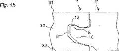
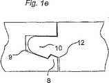
図1のa乃至eは、表面31、コア30、及び後側32を持ち、接合縁部分に従来技術の機械式接合システムが設けられたフロアボード1、1’を示す。垂直方向係止手段は、溝9及びタング10を含む。水平方向係止手段は、係止溝12と協働する係止エレメント8を含む。図1のa及びcによる接合システムは、係止エレメント8を支持するか或いは係止エレメント8が一体に形成されたストリップ6を後側32に備えている。図1のb、d、及びeによる係止システムは、係止エレメント8及び係止溝12がタング/溝に形成されていることによりこれから区別される。図1のa、b、及びcによる係止システムは、内方への傾け、接合縁部に沿った挿入、スナップ嵌めによって接合できるのに対し、図1のd及びeによる係止システムは、水平方向スナップ嵌めだけで接合できる。 1a to 1e show a
図2のa乃至eは、傾け、接合縁部に沿って挿入(図2のd参照)し、又はスナップ嵌め(図2のe参照)によって別の同様のフロアボード1’に接合できる周知の機械式接合システムを持つ周知のフロアボード1を示す。この種のフロアボードは、長側部4aについて、長側部4bだけとしか接合できない。これは、タング10をタングに対して、又は溝9を溝に対して接合できないためである。このことは短側部5a及び5bにも当てはまる。 2a to 2e are well known that can be joined to another similar floorboard 1 'by tilting, inserting along the joining edge (see d of FIG. 2), or by snap fit (see e of FIG. 2). 1 shows a known
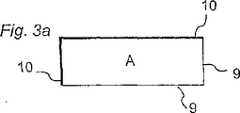
図3のa及びbは、周知の設置方法及び周知の敷設パターンを示す。図3のaでは、長側部及び短側部のタング側10を太線で示す。機械式連結手段を持つ木製及び積層体製のフローリングの設置で今日使用されている方法を図3のbに示す。同じボードを短側部をオフセットさせた平行な列をなして敷設する。 3a and 3b show a known installation method and a known laying pattern. In FIG. 3 a, the long side and the short
図4のa及びbは、二つの矩形フロアボードを示す。これらのフロアボードは、本発明による第1種類Aのフロアボード及び第2種類Bのフロアボードであり、これらのフロアボードの長側部4a及び4bの長さは、この実施例では、短側部5a、5bの長さの3倍である。これらのフロアボードは、第1垂直−水平係止手段対(連結手段とも呼ばれる)を有し、これは、第2垂直−水平係止手段対と協働する。これらの2つの種類は、この実施例では、係止手段の位置が鏡像をなして逆になっていることを除き、同じである。第1の一対の係止手段9を第2の一対の係止手段に接合するとき、これらの係止手段9、10により、長側部を短側部に対して接合できる。この実施例では、スナップ嵌め及び内方への傾けの両方ばかりでなく、接合縁部に沿った挿入でも接合を行うことができる。幾つかの変形例を使用できる。これらの二つの種類のフロアボードは、必ずしも同じ形式でなくてもよく、係止手段は、上述のように長側部を短側部に対して接合できるのであれば、形状が異なっていてもよい。連結手段は、同じ材料でできていてもよいし、異なる材料でできていてもよく、又は材料特性が異なる同じ材料でできていてもよい。例えば、連結手段はプラスチック製であってもよいし金属製であってもよい。これらの手段は、フロアボードと同じであるが含浸等の改質処理を施した材料でできていてもよい。 4a and 4b show two rectangular floorboards. These floor boards are the first type A floor board and the second type B floor board according to the present invention, and the lengths of the
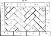
図5のa及びbは、長側部を短側部に対して杉綾パターンで接合した図4のa及びbによるフロアボードでできた本発明によるフロアを示す。敷設手順は、例えば図5に示す通りであり、ボードを1から22まで番号順に敷設する。 FIGS. 5a and 5b show a floor according to the invention made of the floorboard according to FIGS. 4a and 4b with the long side joined to the short side in a herringbone pattern. The laying procedure is as shown in FIG. 5, for example, and the boards are laid out in the order of numbers from 1 to 22.
本発明は、多くの様々な大きさのフロアボードに適用できる。例えば、伝統的なパターンをなした寄木フロアの木材ブロックとほぼ同じ大きさであってもよい。幅は例えば7cm乃至9cmで変化させることができ、長さは40cm乃至80cmである。しかしながら、寄木フロアや積層フロア用の市販の大きさのフロアボードに本発明を適用できる。この他の大きさも考えられる。様々な種類のパターンを形成するため、様々な種類のボード(例えばA及びB)を様々な大きさにすることもできる。更に、同じフローリングの異なるフロアボードで様々な材料を使用できる。適当な組み合わせは、例えば、木材−積層体、積層体−リノリウム、及び木材−リノリウムである。ニードルフェルト等の人工ファイバを、例えば木材ファイバをベースとしたHDF等のボードに適用することによってでできた表面によってフローティングフロアボードを製造することもできる。次いで、木材フロア及び積層体フロアをこのような人工ファイバフロアと組み合わせることができる。材料のこうした組み合わせは、フロアボードの厚さが好ましくは同じであり、接合システムにより異なるフロアボードを接合できる場合に特に有利である。材料のこのような組み合わせにより、音響特性や丈夫さ等の性質が異なる部分を含むフロアを製造できる。例えば、通路では非常に丈夫な材料を使用できる。勿論、これらの組み合わせフロアは、従来の方法でも接合できる。 The present invention is applicable to many different sizes of floorboards. For example, it may be approximately the same size as a wood block on a parquet floor having a traditional pattern. The width can be changed, for example, from 7 cm to 9 cm, and the length is from 40 cm to 80 cm. However, the present invention can be applied to commercially available floor boards for parquet floors and laminated floors. Other sizes are also conceivable. Different types of boards (eg, A and B) can be sized to form different types of patterns. In addition, various materials can be used on different floorboards with the same flooring. Suitable combinations are, for example, wood-laminate, laminate-linoleum, and wood-linoleum. Floating floorboards can also be manufactured with surfaces made by applying artificial fibers such as needle felt to boards such as wood fiber based HDFs. The wood floor and laminate floor can then be combined with such an artificial fiber floor. Such a combination of materials is particularly advantageous when the floorboard thickness is preferably the same and different floorboards can be joined by the joining system. Such a combination of materials can produce floors that include portions with different properties such as acoustic properties and robustness. For example, a very strong material can be used in the passage. Of course, these combination floors can also be joined by conventional methods.
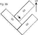
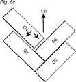
図6、図7、及び図8は、フロアボードを使用して杉綾パターンフロアを設置するための別の方法を示す。全ての図において、LDは、敷設方向を示す。 6, 7 and 8 show another method for installing a herb pattern floor using a floorboard. In all the drawings, LD indicates the laying direction.
図6は、第1の設置方法を示す。図6のaでは、第1フロアボードG1及び第2フロアボードG2が相互連結されており、互いに長側部が短側部に係止されている。この場合、相互連結は、スナップ嵌め、接合縁部に沿った挿入、又は内方への傾けのいずれかによって行うことができる。このような内方への傾けは、本質的に水平方向の軸線を中心として回転させることによって行われる。第3フロアボードG3は、先ず最初に長側部をフロアボードG2の長側部に連結して係止した後、係止状態で、フロアボードG2に沿って変位し、その短側部をフロアボードG1に連結し又は係止することによって追加される。フロアボードG2との連結は、内方への傾け又はスナップ嵌めによって行うことができるのに対し、フロアボードG1との連結はスナップ嵌めによって行われる。 FIG. 6 shows a first installation method. In FIG. 6 a, the first floor board G <b> 1 and the second floor board G <b> 2 are interconnected, and the long side portions are locked to the short side portions. In this case, the interconnection can be made either by snap-fit, insertion along the joining edge, or inward tilt. Such inward tilting is performed by rotating about an essentially horizontal axis. First, the third floor board G3 is first coupled with the long side portion to the long side portion of the floor board G2 and locked, and then is displaced along the floor board G2 in the locked state. It is added by connecting or locking to the board G1. The connection with the floor board G2 can be made by inward tilting or snap fitting, while the connection with the floor board G1 is made by snap fitting.
図6のbは、第3フロアボードG3を追加するための別の方法を示す。この場合、 先ず最初にフロアボードG3の短側部をフロアボードG1の長側部に連結した後、係止状態でフロアボードG1に沿って変位し、フロアボードG2と互いにスナップ嵌めすることによって互いに連結し又は係止する。図6のa及びbによる方法は、本質的に同じ結果をもたらす。 FIG. 6b shows another method for adding a third floorboard G3. In this case, first, the short side portion of the floor board G3 is first connected to the long side portion of the floor board G1, then displaced along the floor board G1 in a locked state, and snap-fitted to the floor board G2 to each other. Connect or lock. The method according to FIGS. 6a and b gives essentially the same result.
図6のcは、更に追加のフロアボードG4をフロアボードG3が追加されたのと同じ方法で、即ち図6のaによる連結手順、又は図6のbによる連結手順のいずれかによって、追加する方法を示す。次いで、更に追加のフロアボードをこれらの工程を繰り返すことによって追加できる。 Fig. 6c adds an additional floor board G4 in the same way that the floor board G3 was added, i.e. either by the coupling procedure according to Fig. 6a or by the coupling procedure according to Fig. 6b. The method is shown. Additional floorboards can then be added by repeating these steps.
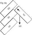
図7のaは、第2の設置方法を示す。図7のaでは、二つのフロアボードG1及びG2は、上述の図6のaにおけるのと同じ方法で互いに係止されているか或いは連結されている。次いで、フロアボードG3を、本質的に同じ連結手段を持つ均等な接合縁部を形成するフロアボードG1の短側部及びフロアボードG2の長側部と連結し又は係止する。かくして、フロアボードG3は、内方への傾け、接合縁部に沿った挿入、又はスナップ嵌めの何れかによって連結でき、場合によっては互いに係止できる。ボードG3の位置は、短側部がフロアボードG1の長側部と整合するようにフロアボードを接合縁部に沿って変位することによって調節でき、これにより均等な接合縁部を形成する。図7のbは、フロアボードG1及びG3が形成する共通の接合縁部に、フロアボード接合4を、フロアボード接合3を追加したのと同じ方法で接合する方法を示す。 FIG. 7 a shows a second installation method. In FIG. 7a, the two floor boards G1 and G2 are locked or connected to each other in the same way as in FIG. 6a above. The floorboard G3 is then connected or locked to the short side of the floorboard G1 and the long side of the floorboard G2 forming an equal joining edge with essentially the same connecting means. Thus, the floorboards G3 can be connected by either inward tilting, insertion along the joining edge, or snap fit, and in some cases can be locked together. The position of the board G3 can be adjusted by displacing the floorboard along the joining edge so that the short side is aligned with the long side of the floorboard G1, thereby forming an even joining edge. FIG. 7b shows a method of joining the floorboard joint 4 to the common joint edge formed by the floorboards G1 and G3 in the same manner as the
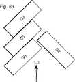
図8は、第3の設置方法を示す。 FIG. 8 shows a third installation method.
図8のaは、複数のフロアボードG0、G1、及びG3を、長側部を長側部に対して配置し且つ接合し、これらのフロアボードの短側部を互いに対してずらして配置する方法を示す。短側部のずれは、好ましくは、フロアボードG2の幅と同じである。例えば、図9に更に詳細に示すフィッティング片を使用することによってずらすことができる。フロアボードG2の追加は二つの方法で行うことができる。 FIG. 8a shows a plurality of floor boards G0, G1, and G3, with the long side portions arranged and joined to the long side portions, and the short side portions of these floor boards being arranged offset from each other. The method is shown. The short side shift is preferably the same as the width of the floor board G2. For example, it can be shifted by using a fitting piece shown in more detail in FIG. The addition of the floor board G2 can be performed in two ways.
図8のaは、フロアボードG2の長側部を、先ず最初に、内方への傾け、挿入、又はスナップ嵌めでフロアボードG1の短側部に接合する方法を示す。次いで、フロアボードG2を、連結された状態で、フロアボードG1の短側部に沿って、フロアボードG2の短側部がフロアボードG3の長側部にスナップ嵌めによって連結されるまで変位させる。 FIG. 8a shows how the long side of the floorboard G2 is first joined to the short side of the floorboard G1 by inward tilting, insertion or snapping. Next, the floorboard G2 is displaced in a connected state until the short side portion of the floorboard G2 is connected to the long side portion of the floorboard G3 by a snap fit along the short side portion of the floorboard G1.
図8のbは、フロアボードG2を追加する第2の方法を示す。この方法では、先ず最初に短側部をフロアボードG3の長側部に内方への傾け、挿入、又はスナップ嵌めによって連結した後、連結状態で、フロアボードG2の長側部がフロアボードG1の短側部にスナップ嵌めで連結されるまで、フロアボードG3の長側部に沿って変位させる。 FIG. 8b shows a second method of adding the floorboard G2. In this method, first, after the short side portion is connected to the long side portion of the floor board G3 inwardly by insertion, insertion, or snap fitting, the long side portion of the floor board G2 is connected to the floor board G1 in the connected state. It is displaced along the long side part of the floor board G3 until it is connected to the short side part by snap fitting.
図8のcは、更に追加のフロアボードG4を追加する方法を示す。先ず最初にフロアボードG4の一方の長側部をフロアボードG2の長側部に連結する。次いで、フロアボードG4をフロアボードG2とG0との間で移動する。その結果、フロアボードG4の他方の長側部及びフロアボードG0の短側部が変位移動によって連結される。ここで、フロアボードG4の連結手段はフロアボードG0の短側部の連結手段内に真っ直ぐに変位し、フロアボードG4の短側部の連結手段はフロアボードG1の長側部にスナップ嵌めで連結される。 FIG. 8c shows a method of adding an additional floor board G4. First, one long side portion of the floor board G4 is connected to the long side portion of the floor board G2. Next, the floor board G4 is moved between the floor boards G2 and G0. As a result, the other long side portion of the floor board G4 and the short side portion of the floor board G0 are connected by displacement movement. Here, the connecting means of the floor board G4 is straightly displaced in the connecting means of the short side portion of the floor board G0, and the connecting means of the short side portion of the floor board G4 is connected to the long side portion of the floor board G1 by a snap fit. Is done.
更に追加のフロアボードの追加は図8のcによる工程を繰り返すことによって行われる。 Furthermore, the addition of an additional floor board is performed by repeating the process according to FIG.
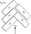
図8のd及びeは、ボードG0、G1、G3からなる設置済の列にフロアボードを追加する別の方法を示す。 FIGS. 8d and 8e show another way of adding a floorboard to the installed row of boards G0, G1, G3.
図8のdでは、フロアボードG0及びG1へのフロアボードG2の連結は、先ず最初にフロアボードG2の長側部を、フロアボードG0の短側部に、内方への傾け、挿入、又はスナップ嵌めによって連結した後、連結状態で、その短側部がフロアボードG1の長側部にスナップ嵌めで連結されるまで変位させるか或いは、先ず最初にフロアボードG2の短側部をフロアボードG1の長側部に、内方への傾け、挿入、又はスナップ嵌めによって連結した後、連結状態で、フロアボードG1に沿ってその長側部がフロアボードG1の短側部にスナップ嵌めで連結されるまで変位させるかのいずれかによって行われる。 In FIG. 8d, the floorboard G2 is connected to the floorboards G0 and G1 by first inclining and inserting the long side of the floorboard G2 inwardly into the short side of the floorboard G0, or After connecting by snap fitting, in the connected state, the short side portion is displaced until it is connected to the long side portion of the floor board G1 by snap fitting, or first, the short side portion of the floor board G2 is first moved to the floor board G1. After being connected to the long side portion by inward inclining, insertion, or snap fitting, in the connected state, the long side portion is connected to the short side portion of the floor board G1 by snap fitting along the floor board G1. It is done by either displacing until
図8のeは、更に追加のフロアボードG4の追加を示す。先ず最初に、このフロアボードの長側部を、内方への傾け、スナップ嵌め、又は挿入によって、長側部及び短側部の夫々が互いに整合し、均等な連続した接合縁部を形成するフロアボードG1及びG2に連結する。次いで、フロアボードG4を、この接合縁部に沿って、フロアボードG4の短側部がフロアボードG3の長側部とスナップ嵌めで接合されるまで変位する。別の態様では、逆の接合手順を使用してもよい。即ち、先ず最初にフロアボードG4の短側部をフロアボードG3の長側部に、内方への傾け、挿入、又はスナップ嵌めによって接合した後、フロアボードG4を、連結された状態で、フロアボードG3の長側部に沿って、フロアボードG4の長側部がフロアボードG1及びG2の夫々の短側部及び長側部に連結するまで変位させる。 FIG. 8e shows the addition of an additional floor board G4. First, the long side of the floorboard is tilted inward, snapped, or inserted so that the long and short sides are aligned with each other to form an even continuous joint edge. Connect to floor boards G1 and G2. Next, the floor board G4 is displaced along the joining edge until the short side portion of the floor board G4 is joined to the long side portion of the floor board G3 by snap fitting. In another aspect, the reverse joining procedure may be used. That is, first, after the short side portion of the floor board G4 is joined to the long side portion of the floor board G3 by inward inclining, insertion, or snap fitting, the floor board G4 is connected to the floor board G4. Along the long side portion of the board G3, the floor board G4 is displaced until the long side portion of the floor board G4 is connected to the short side portion and the long side portion of the floor boards G1 and G2, respectively.
現在の設置状況によって必要とされる場合には、上述の設置方法を組み合わせることができる。概して、二つの接合縁部を相互連結し、即ち互いに係止する場合、接合縁部の相互連結又は相互係止に用いられる接合縁部の部分は、接合縁部の比較的大きな部分であってもよいし、又は比較的小さな部分であってもよい。かくして、夫々のフロアボードの接合縁部の小さな部分しか用いることができない場合でも、二つのフロアボードの相互連結即ち相互係止を行うことができる。 If required by the current installation situation, the above installation methods can be combined. In general, when two joining edges are interconnected, i.e., locked together, the portion of the joining edge used to interconnect or interlock the joining edges is a relatively large portion of the joining edge. Or a relatively small portion. Thus, even if only a small part of the joining edge of each floorboard can be used, the two floorboards can be interconnected.
図9のa乃至eは、壁に沿ってフロアを終端する様々な方法を示す。一つの簡単な方法は、フロアボードの端部を、壁に連結される形状になるように切断するだけである。切断後、切除した縁部を従来技術の方法でベースボードで覆ってもよい。 FIGS. 9a-9e illustrate various ways of terminating the floor along the wall. One simple method is to cut the end of the floorboard into a shape that is connected to the wall. After cutting, the excised edge may be covered with a baseboard in the manner of the prior art.
第2の別の方法は、壁に沿って敷設したフロアボードでできた一つ又はそれ以上の列を含むフレームを使用することである。フレームは、数字を付したフロアボード1乃至13に従った所定の形状を備えている。このように敷設すると、A13を除くフレームの全てのフロアボードを機械的に接合できる。他のフロアボードは、設置と関連して切除でき、接着剤を使用した適当な方法で、又は例えば手動式研削機によってタング溝又はタングを形成することによって連結できる。別の態様では、図9のc及びdに示すように、タング溝及び緩いタングを使用できる。 A second alternative is to use a frame that includes one or more rows of floorboards laid along the wall. The frame has a predetermined shape according to
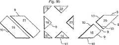
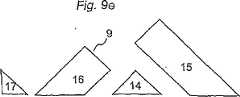
第3の変形例は、フレーム1乃至13を、図9のbに示す10種類の異なる工場生産フィッティング片14乃至23で埋めることである。これらのフィッティング片は、溝側9(細線で示す)及びタング側10(太線で示す)に機械式接合システムを備えている。これらのフィッティング片は、三角形や台形等の様々な形状であってもよく、好ましくは、他のフロアボードを装着するのに適した角度に合わせて切断された斜めの側部を有する 。通常の杉綾寄木フロアでは、この角度は好ましくは45°である。更に、図9に示すのとは異なるパターン及び角度が考えられる。一実施例によれば、隣接したフロアボードと協働するため、図9のbに示すように、フィッティング片の全ての縁部に連結手段が設けられる。更に、フィッティング片の形成は、フロアボードを適当な形状に合わせて切断した後、設置現場で持ち運び式工具セットを使用することによって、又は切断後に機械加工を行うために工場や作業所に送ったフィッティング片によってのいずれかによって連結手段を形成することによって行うことができる。 A third modification is to fill the
フロアボードの連結手段の設計についてここで述べたことは、適当な部分において、フィッティング片にも適用できる。 What has been described here about the design of the means for connecting the floorboards can also be applied to the fitting pieces, where appropriate.
図9のcに示すようにフィッティング片に溝9だけが設けられており、接着剤によって接合するために緩いタング10を使用する場合、又は図9のdによる機械式接合システムを構成する緩いタング10を使用する場合、一組中のフィッティング片の数を大幅に減らすことができる。これは、これらのフィッティング片が鏡像をなして逆にできるためである。好ましい変形例では、フィッティング片の数を図9で参照番号14、15、16、及び17を付した4種類の異なるフィッティング片に減らすことができる。工場で形成した溝及び緩いタングにより設置を大幅に簡単にできる。これは、フロアボードの表面に関する溝の垂直方向位置を、例えば手工具を使用した場合に可能であるよりも高い精度で定めることができるためである。緩いタング10は、例えば、プラスチック又はアルミニウム製の押出し形材でできていてもよい。木材繊維を基材とした適当なボード、木材、等を機械加工することによっても形成できる。 As shown in FIG. 9c, only the
図9のdに示す緩いタング10は、垂直係止手段及び水平係止手段の両方を含み、及びかくして、ボードの全ての側部を他の同様のフロアボードに機械的に接合できる。緩いタング10は、様々な方法で形成でき、一つ又はそれ以上の水平方向連結手段が両側に設けられ、スナップ嵌め、挿入、及び/又は内方への傾けによって接合するように設計できる。図1のb、d、及びeに示す種類のタング10の変形例、並びに他の周知の係止システムを、係止エレメント8を備えた二つの側部を持つ緩いタングエレメントを構成するように変更できる。これらの係止エレメント8は、図9のdに示すように、係止溝12を備えた適当な協働タング溝9が接合縁部に形成されたフロアボードを係止する。 The
更に、フロアボードの切除縁部に取り付けることができ、隣接したフロアボードの係止手段と相互連結又は相互係止で協働するようになったストリップを提供できる。ストリップは、木材、アルミニウム、プラスチック、等の適当な材料で形成でき、例えば切除により機械式係止システムが一体に設けられていないフロアボードの縁部に取り付けられるように適合できる。ストリップは、便利には、他のフロアボードに設けられた連結手段の種類に合わせて調節され、切削を予め行って又は行わないで取り付けることができる。ストリップは、必要に応じて所定の長さを切断することによって形成できる。適当には、ストリップは、フロアボードに、機械的に、例えばフロアボードの或る種のストリップ、凹所、又は穴と係合することによって取り付けられるが、接着剤、ねじ、釘、クリップ、接着剤テープ、又は他のファスニング手段が考えられる。 Furthermore, it is possible to provide a strip which can be attached to the cutting edge of the floorboard and adapted to cooperate or interlock with the locking means of the adjacent floorboard. The strip can be formed of any suitable material such as wood, aluminum, plastic, etc., and can be adapted to be attached to the edge of a floorboard that is not integrally provided with a mechanical locking system, for example by cutting. The strip is conveniently adjusted to the type of connecting means provided on the other floorboard and can be mounted with or without prior cutting. The strip can be formed by cutting a predetermined length as required. Suitably, the strip is attached to the floorboard mechanically, for example by engaging certain strips, recesses or holes in the floorboard, but with adhesives, screws, nails, clips, adhesives An agent tape or other fastening means is conceivable.
更に、工場で形成した連結手段を全ての縁部に備えたフィッティング片及び構成が異なる連結手段を持つフィッティング片の両方が同じフロアで使用されるように、実施例を組み合わせることもできる。例えば、工場で制作されたフィッティング片は、このような場合には、フレームを構成するフロアボードと実際の杉綾パターンを構成するフロアボードとの間の装着を簡単にするのに寄与する。このシステムによって、フレームを一つ又はそれ以上の壁に沿って敷設でき、その後、杉綾パターンをフレームにフィッティング片によって連結し、フロアの敷設を部屋の第1隅部から始める。その後、他の壁に対する連結の調節を、他の種類の連結手段を使用して行うことができ、従来の方法で連結手段を全く使用せずに行うことができる。 Furthermore, the embodiments can also be combined so that both fitting pieces with connecting means formed at the factory on all edges and fitting pieces with connecting means of different construction are used on the same floor. For example, a fitting piece produced in a factory contributes to simplifying the mounting between the floor board constituting the frame and the floor board constituting the actual Sugaya pattern in such a case. With this system, the frame can be laid along one or more walls, after which the herringbone pattern is connected to the frame by a fitting piece and floor laying begins at the first corner of the room. Thereafter, the adjustment of the connection to the other wall can be made using other types of connection means and can be done in the conventional manner without any connection means.
図10のa、b、及びcは、ダイヤモンドパターンでの敷設を示す。この実施例でも、敷設を合理的に行うため、係止位置での変位及びスナップ嵌めを使用できる。 FIGS. 10a, 10b and 10c show laying with a diamond pattern. Also in this embodiment, displacement and snap fit at the locking position can be used to reasonably lay.
図10のaは、2種類のフロアボードA及びBを敷設できるパターンを示す。図10のaでフロアボードに付した番号は、敷設順序を表す。 FIG. 10a shows a pattern in which two types of floor boards A and B can be laid. The numbers given to the floor boards in FIG. 10a represent the laying order.
図10のbは、図10のaによるパターンを形成するために短側部を長側部に接合する、2種類のフロアボードA及びBを接合する方法を示す。 FIG. 10b shows a method of joining two types of floorboards A and B, joining the short side to the long side to form the pattern according to FIG. 10a.
図10のcは、対称パターンの敷設を容易にするための方法を示す。ボードBの短側部と整合した他のボードAの敷設を用意にするため、ボードA4をオフセットして敷設する。次いで、連続的に敷設する前にボードA4を正しい位置に押し戻すが、これは、ボードAとボードBの間の中央にあってもよく、かくしてダイヤモンドをオフセット列をなして敷設できる。図10によるダイヤモンドパターンは、有利には、例えばいわゆるダッチ(Dutch)パターンを形成するために大きさが異なる木材ブロックと組み合わせることができる。 FIG. 10c shows a method for facilitating the laying of a symmetrical pattern. To prepare for laying another board A aligned with the short side of board B, board A4 is laid offset. The board A4 is then pushed back into position before successive laying, which may be in the middle between board A and board B, so that the diamond can be laid in an offset row. The diamond pattern according to FIG. 10 can advantageously be combined with wood blocks of different sizes, for example to form a so-called Dutch pattern.
図11は、本発明によるフロアボードを製造するための方法を概略に示す。重要なことには、一組の工具及びフロアボードブランクを互いに対して変位することによってフロアボードが合理的に製造される。工具の組は、有利には、一つの同じ変位移動で二つの両縁部分に機械加工を施すことができる。これは、夫々の係止手段を形成するための工具109及び110からなる組をフロアボードの移動経路Fの各側に配置することによって行うことができる。工具の組は、好ましくは、当業者に周知の方法で輪郭を急速に機械加工するように寸法が定められた一つ又はそれ以上の研削工具を含む。図11による例では、垂直方向係止手段の溝9が形成される側部を機械加工するために一組の工具109を使用し、垂直方向係止手段のタング10が形成される側部を機械加工するために別の組をなした工具110を使用する。 FIG. 11 schematically shows a method for manufacturing a floorboard according to the invention. Importantly, the floorboard is reasonably manufactured by displacing a set of tools and a floorboard blank relative to each other. The set of tools can advantageously be machined on two edge portions with one and the same displacement movement. This can be done by placing a set of tools 109 and 110 to form the respective locking means on each side of the floorboard movement path F. The tool set preferably includes one or more grinding tools dimensioned to rapidly machine the contour in a manner well known to those skilled in the art. In the example according to FIG. 11, a set of tools 109 is used to machine the side where the
フロアボードの一対の両縁部分に係止手段を形成する第1機械加工工程101の後、フロアボードの他の対をなした両縁部に係止手段を形成する第2機械加工工程105を実施する。この第2機械加工工程105は、工具組及びフロアボードブランクを、互いに対し、第1方向に対して好ましくは垂直な第2方向に変位することによって、第1機械加工工程と同様に行われる。機械加工工程101、105は、当業者に周知の方法で行われ、これらの順序を変えることは本発明の範疇に含まれる。 After a first machining step 101 for forming locking means on a pair of both edges of the floorboard, a second machining step 105 for forming locking means on both edges of the other pair of floorboards. carry out. This second machining step 105 is performed in the same way as the first machining step by displacing the tool set and the floorboard blank with respect to each other in a second direction, preferably perpendicular to the first direction. The machining steps 101 and 105 are performed by a method well known to those skilled in the art, and changing the order of these is included in the scope of the present invention.
概して、大量のフロアボードの製造が完全に自動化される。かくして、フロアボードは、2つの製造工程間で自動的に移動される。これらの製造工程は、先ず最初にフロアボードブランクを、工具109a及び110aを含む第1の組を含む第1機械加工装置を通して第1方向F1でフロアボードの長さ方向に移動し、次いで、工具109b及び110bを含む第2の組を含む第2機械加工装置を通って第1方向に対して本質的に垂直な方向F2で移動するように配置できる。この方法によって製造されたフロアボードは全て、同じ種類であり、即ち本発明によるA又はBである。 In general, the production of large quantities of floorboard is fully automated. Thus, the floorboard is automatically moved between the two manufacturing processes. These manufacturing processes first move the floorboard blank through the first machining apparatus including the first set including the tools 109a and 110a in the length direction of the floorboard in the first direction F1, and then to the tool It can be arranged to move in a direction F2 essentially perpendicular to the first direction through a second machining device comprising a second set comprising 109b and 110b. All floorboards produced by this method are of the same type, ie A or B according to the invention.
しかしながら、本発明によれば、本発明による一つの種類のフロアボードを製造するための現存の製造工場を、両種類のフロアボードを同じ工具組を使用して製造するように調節できる。これは、第1の種類のフロアボード(例えばA)を上文中に説明したように、即ち二つの機械加工工程で製造すると同時に、第2の種類のフロアボード(例えばB)を構成するフロアボードブランクを、第1機械加工工程101の後、工程104でその平面内で半回転させることによって行われる。次いで、フロアボードブランクに第2機械加工工程105を加え続ける。その結果、フロアボードBでの一対の連結手段の位置がフロアボードAと比べて逆になる。フロアボードBは、かくして、フロアボードAに関して鏡像をなして逆になる。 However, according to the present invention, an existing manufacturing plant for manufacturing one type of floorboard according to the present invention can be adjusted to manufacture both types of floorboards using the same tool set. This is because the first kind of floorboard (eg A) is produced as described above, that is, it is manufactured in two machining steps and at the same time constitutes the second kind of floorboard (eg B). The blank is performed after the first machining step 101 by half rotation in its plane at step 104. The second machining step 105 is then continued on the floorboard blank. As a result, the position of the pair of connecting means on the floor board B is reversed compared to the floor board A. Floor board B is thus mirror imaged with respect to floor board A and reversed.
いずれのボードを回転させるべきかは、制御システム103からの情報に基づいて制御できる。制御システム103は、フロアボードブランクを、第1機械加工工程101の後に第2製造工程105に移送される前に回転する回転装置102を制御する。 Which board is to be rotated can be controlled based on information from the control system 103. The control system 103 controls the rotating device 102 that rotates the floorboard blank before being transferred to the second manufacturing step 105 after the first machining step 101.
この好ましい方法によるフロアボードA及びBは、同じラインで及び同じ工程設定で製造され、二つのフロアボードは長さ及び幅が正確に同じである。これにより、パターンの対称敷設が大幅に容易になる。 Floor boards A and B according to this preferred method are manufactured on the same line and with the same process settings, and the two floor boards are exactly the same in length and width. This greatly facilitates pattern laying.
フロアボードの設置後、接合システムを損傷することなくフロアボードを取り外して再敷設できるのが有利である。フロアボードの取り外しは、便利には、本質的に設置方法の逆を行う方法によって行われる。多くの場合に短側部である一方の側部を、フロアボードを水平方向に引っ張ってスナップ外し(snapping−out)で係止エレメント8を係止溝12から離すことによって取り外す。次いで、最も便利には長側部である他方の側部を、上方への傾け又はスナップ外しによって取り外すことができる。 Advantageously, after installation of the floorboard, the floorboard can be removed and re-laid without damaging the joining system. The removal of the floorboard is conveniently done by a method that essentially reverses the installation method. One side, which is often the short side, is removed by pulling the floorboard horizontally and snapping-out to release the
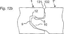
図12のa乃至dは、フロアボードを外すための様々な変形例を示す。図12のaでは、フロアボード1’は、短側部の後側32にグリップ工具121用のグリップ溝120を備えている。グリップ工具は、そのグリップ手段122がグリップ溝121と係合できる。このグリップ手段は、フロアボードの下側32の外側の工具手段に圧力又は衝撃を本質的に水平方向Kに加えることによってボードを損傷することなく取り外すことができる手段123に連結されている。力は、例えば衝撃(例えばハンマーやこん棒を使用し、ハンドル等のところで引っ張ったりぐいっと押したりする)によって加えることができる。グリップ工具は、別の態様では、そのグリップ手段が、フロアボードの別の部分、例えば短側部の接合システムの設計に応じて係止溝12又は係止エレメント8と係合するように設計できる。スナップ外しは、例えば短側部に設けられた係止エレメントを、スナップ外し及びかくして取り外しを例えば長側部についてよりも低い引っ張り応力で行うことができるように、例えば長側部におけるよりも低く形成することによって又は半径を変えることによって、容易に行うことができる。従って、長側部の接合システムは、例えば図12のaに従って設計でき、短側部を図12のbに従って設計でき、この場合、接合システムは、係止エレメント8が低いことを除くと同じ形状を有する。図12のbは、更に、長側部及び/又は短側部に面取り部分131、132を持つように接合縁部を形成できることを示す。フロアボードを、図5のbに従って長側部を短側部に対して所定角度で敷設する場合には、長側部は、特に、例えば大きな摩擦、接着剤、機械的手段、等によって長側部に沿った平行変位が妨げられたり不可能になった場合に、短側部が分離しないようにする。このような敷設パターンでは、短側部を図12のcに従って垂直方向係止手段だけを備えて形成してもよいし、図12のdにおけるように係止手段を全く持たずに形成してもよい。平行な列等の他のパターンで敷設された他の種類の機械的に接合されたフロアボードを外すのにもグリップ工具を使用できる。設置方法、再使用のための丈夫さ及び分解の両方に関して最適のフローリングを提供するため、連結手段及び設置方法の実施例の複数の様々な組み合わせが可能であるということは理解されよう。 12a to 12d show various modifications for removing the floorboard. In FIG. 12 a, the
図13のa乃至dは、長側部及び短側部が別の実施例に従ってどのように形成されるのかを示す。図13のaの長側部4a及び4bは、内方への傾けによって接合できる。好ましい実施例では、フロアボードは、水平方向スナップ嵌めを行うことができるのに十分にストリップ6を下方に曲げることができない材料で形成されている。図13のbは、上述のフロアボードの短側部5a及び5bを示す。係止エレメント8は、長側部に設けられているよりも低く形成されており、係止溝の係止面は比較的小さく形成されている。この実施例では、端部側部は、水平方向で係止できない。図13のc及びdは、内方への傾け及びスナップ嵌めによって長側部を短側部に対して係止できることを示す。これは、短側部に設けられた改良係止システムが、フロアボードを水平方向に接合し互いにスナップ嵌めする上でストリップ6を僅かに下方に曲げるだけでよいためである。長側部4bは、この実施例では、装飾溝133を備えている。この溝は、一方の接合縁部だけに設けられている。ボード1、1’の両接合縁部に装飾溝が設けられている場合よりも接合縁部が見え難いという利点がある。更に、製造が簡単になる。例えば短側部に設けられた係止システムにタング10が設けられていない場合には、フロアボードは、水平方向だけが係止される。FIGS. 13a-d show how the long and short sides are formed according to another embodiment. The
本発明者は、多くの様々なパターンを試験した。これらのパターンは、全て、スナップ嵌め可能であり且つ接合システムが鏡像をなして逆になっている形式が同じ又は異なるフロアボードをフローリングの設置で使用する場合に明らかである。基本的には、本発明は、タング及び溝を持つ寄木フロア、及び接着剤や釘を使用してベースに敷設される、かくして接合を随意に行う性能を制限する接合システムを持たない寄木フロアの設置と関連して周知の全てのパターンを提供するために使用できる。四つ以上の側部を持ち第1連結手段対を3、4に又はそれ以上の側部に備えており且つ第2連結手段対を対応する隣接側部に備えたフロアボードも製造できる。更に、二つ以上の異なる協働係止手段対を持つフロアボードも形成できる。互いにスナップ嵌めできる全ての従来の機械式接合システムを使用できる。 The inventor has tested many different patterns. All of these patterns are evident when floor boards are used with the same or different floorboards that are snap-fit and the joint system is mirrored and reversed. Basically, the present invention is for parquet floors with tongues and grooves, and for parquet floors that are laid on the base using adhesives and nails and thus do not have a joining system that limits the ability to join arbitrarily. Can be used to provide all known patterns in connection with installation. It is also possible to produce a floorboard having four or more sides, with first connecting means pairs on three, four or more sides and with second connecting means pairs on the corresponding adjacent sides. Furthermore, a floorboard with two or more different cooperating locking means pairs can be formed. All conventional mechanical joining systems that can be snapped together can be used.
1、1’ 四辺形フロアボード
4a、4b、5a、5b 縁部分
6 下係止ストリップ
8 突出係止エレメント
9、10 連結手段
12 係止溝
31 上面1, 1 '
Claims (13)
Translated fromJapaneseフロアボードは杉綾パターンにより接合され、
長側部(4a,4b)は垂直方向(D1)に沿ってフロアボードを係止するための、タング(10)とタング溝(9)とを有する対の機械的連結手段を有し、
フローリングは、積層体で形成された表面層を有するフロアボードを備え、
フローリングは一方の長側部に設けられ上方へ突出する係止エレメント(8)を有する第2の機械的連結手段を備え、この係止エレメント(8)は隣接するフロアボードの他の縁部に設けられた係止溝(12)と協働してフロアボードを水平方向(D2)に係止するものであり、これにより各連結手段が垂直方向(D1)および水平方向(D2)で内方への傾けによって係止し、これによってタング(10)がタング溝(9)内に受け入れられ、係止エレメント(8)が係止溝(12)内に進入し、
フロアボードの短側部(5a,5b)の少なくとも一方は連結手段(9,10)を有し、
フローリングは異なる2つの種類のフロアボード(A,B)を有し、
一方の種類のフロアボード(A)の一対の両縁部分に沿った連結手段(9,10)は、他方の種類のフロアボード(B)の同じ一対の両縁部分に沿った対応する連結手段(9,10)に対して鏡像をなして逆に配置され、
フロアボード(A)の一対の短側部(5a,5b)における連結手段(9,10)は一方の短側部(5b)をフロアボード(B)の一対の長側部(4a’,4b’)のうち一方の長側部(4b’)に垂直方向(D1)および水平方向(D2)に連結するようになっており、
フロアボード(A)の一対の短側部(5a,5b)における連結手段(9,10)は他方の短側部(5a)をフロアボード(B)の一対の長側部(4a’,4b’)のうち他方の長側部(4a’)に垂直方向(D1)または水平方向(D2)に連結するフローリング。In a flooring comprising a rectangular floorboard (1, 1 ′) having a pair of long sides (4a, 4b) and a pair of short sides (5a, 5b),
The floorboards are joined by a herringbone pattern,
The long sides (4a, 4b) have a pair of mechanical coupling means with tongues (10) and tongue grooves (9) for locking the floorboard along the vertical direction (D1),
The flooring comprises a floorboard having a surface layer formed of a laminate,
The flooring comprises a second mechanical connecting means provided on one long side and having a locking element (8) protruding upwards, which locking element (8) is connected to the other edge of the adjacent floorboard. In cooperation with the provided locking groove (12), the floor board is locked in the horizontal direction (D2), whereby each connecting means is inward in the vertical direction (D1) and the horizontal direction (D2). The tongue (10) is received in the tongue groove (9), the locking element (8) enters the locking groove (12),
At least one of the short sides (5a, 5b) of the floor board has connecting means (9, 10),
The flooring has two different types of floor boards (A, B),
The connecting means (9, 10) along the pair of both edge portions of one type of floorboard (A) are the corresponding connecting means along the same pair of edge portions of the other type of floorboard (B). (9, 10) mirrored with respect to (9, 10)
The connecting means (9, 10) inthe pair of short sides (5a, 5b) of thefloor board (A) is connected tothe pair of long sides(4a ', 4b ) of thefloor board (B).') Is connected to one long side(4b') in the vertical direction (D1) and the horizontal direction (D2),
The connecting means (9, 10) inthe pair of short sides (5a, 5b) of thefloor board (A) is connected tothe pair of long sides(4a ', 4b ) of thefloor board (B). flooring for connecting the vertical direction (D1) or horizontally (D2) to'the other long side(4a outof)').
フロアボード(A)の短側部(5a,5b)の連結手段は、他方の短側部(5a)をフロアボード(B)の他方の長側部(4a’)に、垂直方向(D1)および水平方向(D2)のいずれの方向にも係止しないことを特徴とするフローリング。The flooring of claim 1, wherein
The connecting means for the short sideportions (5a, 5b) of thefloor board (A) is such that the other short side portion (5a) is perpendicular tothe other long side portion(4a ') of thefloor board (B) (D1). And the flooring characterized by not locking in any direction of the horizontal direction (D2).
Applications Claiming Priority (2)
| Application Number | Priority Date | Filing Date | Title |
|---|---|---|---|
| SE0103130ASE525558C2 (en) | 2001-09-20 | 2001-09-20 | System for forming a floor covering, set of floorboards and method for manufacturing two different types of floorboards |
| PCT/SE2002/001731WO2003025307A1 (en) | 2001-09-20 | 2002-09-20 | Flooring and method for laying and manufacturing the same |
Publications (2)
| Publication Number | Publication Date |
|---|---|
| JP2005503502A JP2005503502A (en) | 2005-02-03 |
| JP4485197B2true JP4485197B2 (en) | 2010-06-16 |
Family
ID=20285387
Family Applications (1)
| Application Number | Title | Priority Date | Filing Date |
|---|---|---|---|
| JP2003528920AExpired - LifetimeJP4485197B2 (en) | 2001-09-20 | 2002-09-20 | Flooring |
Country Status (25)
| Country | Link |
|---|---|
| US (3) | US7127860B2 (en) |
| EP (5) | EP1691004B1 (en) |
| JP (1) | JP4485197B2 (en) |
| KR (1) | KR100935067B1 (en) |
| CN (5) | CN101113636B (en) |
| AT (1) | ATE320536T1 (en) |
| AU (1) | AU2002341477B2 (en) |
| BR (1) | BR0212995B1 (en) |
| CA (1) | CA2458830C (en) |
| CY (1) | CY1105032T1 (en) |
| DE (3) | DE20221487U1 (en) |
| DK (1) | DK1427902T3 (en) |
| ES (1) | ES2256545T3 (en) |
| HU (1) | HU229772B1 (en) |
| IL (2) | IL160453A0 (en) |
| NO (1) | NO327626B1 (en) |
| NZ (1) | NZ531735A (en) |
| PL (1) | PL210099B1 (en) |
| PT (1) | PT1427902E (en) |
| RU (1) | RU2291939C2 (en) |
| SE (1) | SE525558C2 (en) |
| SI (1) | SI1427902T1 (en) |
| UA (1) | UA81899C2 (en) |
| WO (1) | WO2003025307A1 (en) |
| ZA (1) | ZA200401539B (en) |
Families Citing this family (202)
| Publication number | Priority date | Publication date | Assignee | Title |
|---|---|---|---|---|
| SE0001325L (en) | 2000-04-10 | 2001-06-25 | Valinge Aluminium Ab | Locking systems for joining floorboards and floorboards provided with such locking systems and floors formed from such floorboards |
| SE509060C2 (en)* | 1996-12-05 | 1998-11-30 | Valinge Aluminium Ab | Method for manufacturing building board such as a floorboard |
| US20020178674A1 (en) | 1993-05-10 | 2002-12-05 | Tony Pervan | System for joining a building board |
| US7386963B2 (en) | 1998-06-03 | 2008-06-17 | Valinge Innovation Ab | Locking system and flooring board |
| SE512290C2 (en) | 1998-06-03 | 2000-02-28 | Valinge Aluminium Ab | Locking system for mechanical joining of floorboards and floorboard provided with the locking system |
| SE514645C2 (en) | 1998-10-06 | 2001-03-26 | Perstorp Flooring Ab | Floor covering material comprising disc-shaped floor elements intended to be joined by separate joint profiles |
| SE517478C2 (en)* | 1999-04-30 | 2002-06-11 | Valinge Aluminium Ab | Locking system for mechanical hoisting of floorboards, floorboard provided with the locking system and method for producing mechanically foldable floorboards |
| ES2168045B2 (en) | 1999-11-05 | 2004-01-01 | Ind Aux Es Faus Sl | NEW DIRECT LAMINATED FLOOR. |
| US8209928B2 (en) | 1999-12-13 | 2012-07-03 | Faus Group | Embossed-in-registration flooring system |
| US6691480B2 (en) | 2002-05-03 | 2004-02-17 | Faus Group | Embossed-in-register panel system |
| SE517183C2 (en)* | 2000-01-24 | 2002-04-23 | Valinge Aluminium Ab | Locking system for mechanical joining of floorboards, floorboard provided with the locking system and method for making such floorboards |
| SE518184C2 (en) | 2000-03-31 | 2002-09-03 | Perstorp Flooring Ab | Floor covering material comprising disc-shaped floor elements which are joined together by means of interconnecting means |
| US6851241B2 (en)* | 2001-01-12 | 2005-02-08 | Valinge Aluminium Ab | Floorboards and methods for production and installation thereof |
| US8028486B2 (en) | 2001-07-27 | 2011-10-04 | Valinge Innovation Ab | Floor panel with sealing means |
| SE525558C2 (en) | 2001-09-20 | 2005-03-08 | Vaelinge Innovation Ab | System for forming a floor covering, set of floorboards and method for manufacturing two different types of floorboards |
| US8250825B2 (en) | 2001-09-20 | 2012-08-28 | Välinge Innovation AB | Flooring and method for laying and manufacturing the same |
| SE525661C2 (en) | 2002-03-20 | 2005-03-29 | Vaelinge Innovation Ab | Floor boards decorative joint portion making system, has surface layer with underlying layer such that adjoining edge with surface has underlying layer parallel to horizontal plane |
| ATE467015T1 (en) | 2002-04-03 | 2010-05-15 | Vaelinge Innovation Ab | FLOOR PANEL WITH INTEGRATED CONNECTING MEANS AND METHOD FOR THE PRODUCTION THEREOF |
| SE525657C2 (en) | 2002-04-08 | 2005-03-29 | Vaelinge Innovation Ab | Flooring boards for floating floors made of at least two different layers of material and semi-finished products for the manufacture of floorboards |
| US8850769B2 (en) | 2002-04-15 | 2014-10-07 | Valinge Innovation Ab | Floorboards for floating floors |
| DK1497510T4 (en)* | 2002-04-22 | 2009-04-14 | Vaelinge Innovation Ab | Floorboards |
| US7739849B2 (en) | 2002-04-22 | 2010-06-22 | Valinge Innovation Ab | Floorboards, flooring systems and methods for manufacturing and installation thereof |
| US7836649B2 (en) | 2002-05-03 | 2010-11-23 | Faus Group, Inc. | Flooring system having microbevels |
| WO2004009931A1 (en)* | 2002-07-19 | 2004-01-29 | E.F.P. Floor Products Fussböden GmbH | Floor panel |
| AU2003296680A1 (en)* | 2003-01-08 | 2004-08-10 | Flooring Industries Ltd. | Floor panel, its laying and manufacturing methods |
| US20040206036A1 (en) | 2003-02-24 | 2004-10-21 | Valinge Aluminium Ab | Floorboard and method for manufacturing thereof |
| ATE471415T1 (en) | 2003-03-06 | 2010-07-15 | Vaelinge Innovation Ab | FLOORING SYSTEMS AND INSTALLATION METHODS |
| US7677001B2 (en)* | 2003-03-06 | 2010-03-16 | Valinge Innovation Ab | Flooring systems and methods for installation |
| US7845140B2 (en) | 2003-03-06 | 2010-12-07 | Valinge Innovation Ab | Flooring and method for installation and manufacturing thereof |
| AT501440A1 (en)* | 2003-03-07 | 2006-09-15 | Kaindl Flooring Gmbh | COVER PLATE |
| US7886497B2 (en) | 2003-12-02 | 2011-02-15 | Valinge Innovation Ab | Floorboard, system and method for forming a flooring, and a flooring formed thereof |
| SE526179C2 (en) | 2003-12-02 | 2005-07-19 | Vaelinge Innovation Ab | Flooring and method of laying |
| SE526333C2 (en) | 2003-12-11 | 2005-08-23 | Pergo Europ Ab | Flooring system with a plurality of different upper decorative surfaces |
| US20050166516A1 (en) | 2004-01-13 | 2005-08-04 | Valinge Aluminium Ab | Floor covering and locking systems |
| US7516588B2 (en) | 2004-01-13 | 2009-04-14 | Valinge Aluminium Ab | Floor covering and locking systems |
| DE102004028757B4 (en)* | 2004-04-02 | 2007-11-15 | hülsta-werke Hüls GmbH & Co. KG. | Panel element for floor, wall and / or ceiling installation and method for laying a covering, in particular a floor, wall and / or ceiling covering |
| US7690160B2 (en)* | 2004-07-23 | 2010-04-06 | Moller Jr Jorgen J | Modular floor tile system with transition edge |
| SE527570C2 (en) | 2004-10-05 | 2006-04-11 | Vaelinge Innovation Ab | Device and method for surface treatment of sheet-shaped material and floor board |
| US7454875B2 (en) | 2004-10-22 | 2008-11-25 | Valinge Aluminium Ab | Mechanical locking system for floor panels |
| ES2378330T3 (en)* | 2004-10-22 | 2012-04-11 | Välinge Innovation AB | A method of providing floor panels with a mechanical locking system |
| US7841144B2 (en) | 2005-03-30 | 2010-11-30 | Valinge Innovation Ab | Mechanical locking system for panels and method of installing same |
| US8201377B2 (en) | 2004-11-05 | 2012-06-19 | Faus Group, Inc. | Flooring system having multiple alignment points |
| JP2006164440A (en)* | 2004-12-09 | 2006-06-22 | Fuji Electric Device Technology Co Ltd | Perpendicular magnetic recording medium and magnetic recording apparatus |
| SI1691005T1 (en)* | 2005-02-15 | 2010-01-29 | Vaelinge Innovation Ab | Method to make a floorboard with compressed edges |
| US8215078B2 (en) | 2005-02-15 | 2012-07-10 | Välinge Innovation Belgium BVBA | Building panel with compressed edges and method of making same |
| US20060191222A1 (en) | 2005-02-28 | 2006-08-31 | Vincente Sabater | Flooring system having large floor pattern |
| US8061104B2 (en) | 2005-05-20 | 2011-11-22 | Valinge Innovation Ab | Mechanical locking system for floor panels |
| DE102005024366A1 (en)* | 2005-05-27 | 2006-11-30 | Kaindl Flooring Gmbh | Method for laying and mechanically connecting panels |
| US20070175144A1 (en)* | 2006-01-11 | 2007-08-02 | Valinge Innovation Ab | V-groove |
| US7854100B2 (en) | 2006-01-12 | 2010-12-21 | Valinge Innovation Ab | Laminate floor panels |
| SE530653C2 (en) | 2006-01-12 | 2008-07-29 | Vaelinge Innovation Ab | Moisture-proof floor board and floor with an elastic surface layer including a decorative groove |
| US8464489B2 (en) | 2006-01-12 | 2013-06-18 | Valinge Innovation Ab | Laminate floor panels |
| SE530520C2 (en)* | 2006-01-12 | 2008-06-24 | Vaelinge Innovation Ab | Laminate Panels |
| EP1808547A1 (en)* | 2006-01-13 | 2007-07-18 | Berry Finance Nv | System comprising a plurality of panels for forming an assembled surface |
| HUE027794T2 (en)* | 2006-04-14 | 2016-11-28 | Yekalon Ind Inc | A floor block, a floor system and a laying method therefor |
| SE533410C2 (en) | 2006-07-11 | 2010-09-14 | Vaelinge Innovation Ab | Floor panels with mechanical locking systems with a flexible and slidable tongue as well as heavy therefore |
| US7861482B2 (en) | 2006-07-14 | 2011-01-04 | Valinge Innovation Ab | Locking system comprising a combination lock for panels |
| DE102006037614B3 (en)* | 2006-08-10 | 2007-12-20 | Guido Schulte | Floor covering, has head spring pre-assembled in slot and protruding over end of slot, and wedge surface formed at slot or head spring such that head spring runs into wedge surface by shifting projecting end of head spring into slot |
| US7824568B2 (en)* | 2006-08-17 | 2010-11-02 | International Business Machines Corporation | Solution for forming polishing slurry, polishing slurry and related methods |
| US8323016B2 (en)* | 2006-09-15 | 2012-12-04 | Valinge Innovation Belgium Bvba | Device and method for compressing an edge of a building panel and a building panel with compressed edges |
| US11725394B2 (en) | 2006-11-15 | 2023-08-15 | Välinge Innovation AB | Mechanical locking of floor panels with vertical folding |
| US8689512B2 (en) | 2006-11-15 | 2014-04-08 | Valinge Innovation Ab | Mechanical locking of floor panels with vertical folding |
| SE531111C2 (en) | 2006-12-08 | 2008-12-23 | Vaelinge Innovation Ab | Mechanical locking of floor panels |
| US20080187710A1 (en)* | 2007-02-05 | 2008-08-07 | Pergo (Europe) Ab | Protective chair mat with or without reversible surface decor |
| DE202007018662U1 (en)* | 2007-03-26 | 2009-02-19 | Kronotec Ag | Panel, in particular floor panel |
| USD611621S1 (en)* | 2007-06-01 | 2010-03-09 | Inventio Ag | Connecting element surface |
| USD611622S1 (en)* | 2007-06-01 | 2010-03-09 | Inventio Ag | Connecting element surface |
| US20080301945A1 (en)* | 2007-06-08 | 2008-12-11 | Kelly Gibson | Method of forming rectangular panels for use in a panelling system |
| CN201103225Y (en)* | 2007-08-02 | 2008-08-20 | 毛振基 | Plastic floor structure |
| US8499521B2 (en)* | 2007-11-07 | 2013-08-06 | Valinge Innovation Ab | Mechanical locking of floor panels with vertical snap folding and an installation method to connect such panels |
| US8353140B2 (en) | 2007-11-07 | 2013-01-15 | Valinge Innovation Ab | Mechanical locking of floor panels with vertical snap folding |
| US7644556B2 (en)* | 2007-11-15 | 2010-01-12 | Correct Building Products, L.L.C. | Planking system and method |
| DE102008003550B4 (en)* | 2008-01-09 | 2009-10-22 | Flooring Technologies Ltd. | Device and method for locking two floor panels |
| MY152779A (en) | 2008-01-31 | 2014-11-28 | Valinge Innovation Ab | Mechanical locking of floor panels, methods to install and uninstall panels, a method and an equipment to produce the locking system, a method to connect a displaceable tongue to a panel and a tongue blank |
| US8505257B2 (en) | 2008-01-31 | 2013-08-13 | Valinge Innovation Ab | Mechanical locking of floor panels |
| CA2623707A1 (en)* | 2008-03-07 | 2009-09-07 | Pierre Trudel | Tongue and groove profile to ease desassembly of floorboards |
| US8112967B2 (en) | 2008-05-15 | 2012-02-14 | Valinge Innovation Ab | Mechanical locking of floor panels |
| DE102008031167B4 (en)* | 2008-07-03 | 2015-07-09 | Flooring Technologies Ltd. | Method for connecting and locking glueless laying floor panels |
| DE202008011589U1 (en)* | 2008-09-01 | 2008-11-27 | Akzenta Paneele + Profile Gmbh | Plastic floor panel with mechanical locking edges |
| PT2208835E (en)* | 2009-01-16 | 2012-07-16 | Flooring Technologies Ltd | Panelling, in particular floor panelling |
| PL2213812T3 (en)* | 2009-01-28 | 2012-07-31 | Vaelinge Innovation Ab | Panelling, in particular floor panelling |
| WO2010087752A1 (en) | 2009-01-30 | 2010-08-05 | Välinge Innovation Belgium BVBA | Mechanical lockings of floor panels and a tongue blank |
| USD656245S1 (en)* | 2009-04-16 | 2012-03-20 | Rene St-Cyr (1996) Inc. | Floor plank |
| ES2543169T3 (en)* | 2009-06-01 | 2015-08-17 | Tandus Flooring, Inc. | Random installation of tiles using a non-random installation technique |
| NL2003019C2 (en) | 2009-06-12 | 2010-12-15 | 4Sight Innovation Bv | FLOOR PANEL AND FLOOR COVERAGE CONSISING OF MULTIPLE OF SUCH FLOOR PANELS. |
| US8931174B2 (en) | 2009-07-31 | 2015-01-13 | Valinge Innovation Ab | Methods and arrangements relating to edge machining of building panels |
| CN102574292B (en)* | 2009-07-31 | 2016-05-18 | 瓦林格创新股份有限公司 | Process relevant method and apparatus to the edge of building panelling |
| US11717901B2 (en) | 2009-07-31 | 2023-08-08 | Valinge Innovation Ab | Methods and arrangements relating to edge machining of building panels |
| US8365499B2 (en) | 2009-09-04 | 2013-02-05 | Valinge Innovation Ab | Resilient floor |
| PL2473687T3 (en) | 2009-09-04 | 2019-10-31 | Vaelinge Innovation Ab | A method of assembling resilient floorboards which are provided with a mechanical locking system |
| US11725395B2 (en) | 2009-09-04 | 2023-08-15 | Välinge Innovation AB | Resilient floor |
| USD660463S1 (en)* | 2009-11-23 | 2012-05-22 | Falquon Gmbh | Panel |
| US8429870B2 (en)* | 2009-12-04 | 2013-04-30 | Mannington Mills, Inc. | Connecting system for surface coverings |
| BR112012013809B1 (en)* | 2009-12-17 | 2019-07-30 | Välinge Innovation AB | METHOD FOR MANUFACTURING FLOOR PANELS |
| PT2339092T (en)* | 2009-12-22 | 2019-07-19 | Flooring Ind Ltd Sarl | Method for producing covering panels |
| CN101881076B (en)* | 2010-06-09 | 2014-07-09 | 黄焕文 | Combined floor capable of being paved conveniently |
| PL4092213T3 (en) | 2010-01-11 | 2024-03-25 | Välinge Innovation AB | Floor covering with interlocking design |
| BR112012016569A2 (en) | 2010-01-12 | 2016-04-05 | Vaelinge Innovation Ab | mechanical locking system for floor panels |
| DE102010004717A1 (en) | 2010-01-15 | 2011-07-21 | Pergo (Europe) Ab | Set of panels comprising retaining profiles with a separate clip and method for introducing the clip |
| CA2786680C (en) | 2010-02-04 | 2018-06-12 | Vaelinge Innovation Ab | Mechanical locking system for floor panels and a tongue therefore |
| US8869481B2 (en)* | 2010-02-19 | 2014-10-28 | Paata Dzigava | Flooring devices, systems, and methods thereof |
| CN102191844B (en)* | 2010-03-11 | 2014-05-14 | 合肥顶呱呱专利研发推广有限公司 | Floor installation method and parts and tools |
| CN102844506B (en) | 2010-04-15 | 2015-08-12 | 巴尔特利奥-斯巴诺吕克斯股份公司 | floor components |
| BE1019331A5 (en)* | 2010-05-10 | 2012-06-05 | Flooring Ind Ltd Sarl | FLOOR PANEL AND METHODS FOR MANUFACTURING FLOOR PANELS. |
| US8925275B2 (en) | 2010-05-10 | 2015-01-06 | Flooring Industries Limited, Sarl | Floor panel |
| CN104831904B (en) | 2010-05-10 | 2017-05-24 | 佩尔戈(欧洲)股份公司 | Set of panels |
| BE1019501A5 (en) | 2010-05-10 | 2012-08-07 | Flooring Ind Ltd Sarl | FLOOR PANEL AND METHOD FOR MANUFACTURING FLOOR PANELS. |
| EP2674547B1 (en)* | 2010-10-20 | 2018-05-02 | Kronoplus Technical AG | Surface covering comprising laminate panels and an extraneous locking element and method for laying the surface |
| US8806832B2 (en) | 2011-03-18 | 2014-08-19 | Inotec Global Limited | Vertical joint system and associated surface covering system |
| UA109938C2 (en) | 2011-05-06 | 2015-10-26 | MECHANICAL LOCKING SYSTEM FOR CONSTRUCTION PANELS | |
| CN102233600A (en)* | 2011-05-30 | 2011-11-09 | 深圳普兰太森新材料科技有限公司 | Wood shaped like inverted V or Z |
| KR101119611B1 (en)* | 2011-06-01 | 2012-03-06 | 주식회사 대진 | Deco tile |
| UA114715C2 (en) | 2011-07-05 | 2017-07-25 | Сералок Інновейшн Аб | Mechanical locking of floor panels with a glued tongue |
| RU2603987C2 (en) | 2011-07-11 | 2016-12-10 | Сералок Инновейшн Аб | Mechanical locking system for floor panels |
| US9725912B2 (en) | 2011-07-11 | 2017-08-08 | Ceraloc Innovation Ab | Mechanical locking system for floor panels |
| US8650826B2 (en) | 2011-07-19 | 2014-02-18 | Valinge Flooring Technology Ab | Mechanical locking system for floor panels |
| US8769905B2 (en) | 2011-08-15 | 2014-07-08 | Valinge Flooring Technology Ab | Mechanical locking system for floor panels |
| US8763340B2 (en) | 2011-08-15 | 2014-07-01 | Valinge Flooring Technology Ab | Mechanical locking system for floor panels |
| US8857126B2 (en) | 2011-08-15 | 2014-10-14 | Valinge Flooring Technology Ab | Mechanical locking system for floor panels |
| US8950147B2 (en)* | 2011-08-22 | 2015-02-10 | Awi Licensing Company | Floor panel and floating floor system incorporating the same |
| JP6105587B2 (en) | 2011-08-29 | 2017-04-05 | セラロック、イノベーション、アクチボラグ | Mechanical locking system for floor panels |
| USD664626S1 (en)* | 2011-09-06 | 2012-07-31 | Tom Devine | Tank support |
| US8726602B2 (en) | 2011-12-06 | 2014-05-20 | Johnsonite Inc. | Interlocking floor tile |
| US8650824B2 (en) | 2011-12-06 | 2014-02-18 | Johnsonite Inc. | Interlocking floor tile |
| US9216541B2 (en) | 2012-04-04 | 2015-12-22 | Valinge Innovation Ab | Method for producing a mechanical locking system for building panels |
| US8596013B2 (en) | 2012-04-04 | 2013-12-03 | Valinge Innovation Ab | Building panel with a mechanical locking system |
| CN104582916A (en) | 2012-06-19 | 2015-04-29 | 瓦林格创新股份有限公司 | Method for dividing a panel into a first panel and a second panel, method of forming a mechanical locking system for locking the first and second panels, and building panels |
| USD694023S1 (en)* | 2012-08-07 | 2013-11-26 | Suncast Technologies, Llc | Resin wicker panel |
| EP2895667B1 (en)* | 2012-08-27 | 2019-12-04 | Pergo (Europe) AB | Panel |
| PL2923012T3 (en) | 2012-11-22 | 2020-04-30 | Ceraloc Innovation Ab | Mechanical locking system for floor panels |
| EA201992325A1 (en) | 2013-03-25 | 2020-05-31 | Велинге Инновейшн Аб | FLOOR PANELS EQUIPPED WITH MECHANICAL FIXING SYSTEM AND METHOD FOR PRODUCING SUCH FIXING SYSTEM |
| PT3014034T (en) | 2013-06-27 | 2019-11-29 | Vaelinge Innovation Ab | Building panel with a mechanical locking system |
| US9726210B2 (en) | 2013-09-16 | 2017-08-08 | Valinge Innovation Ab | Assembled product and a method of assembling the product |
| CN109854597B (en) | 2013-09-16 | 2021-03-19 | 瓦林格创新股份有限公司 | Combination product and method for assembling the same |
| KR102314032B1 (en) | 2013-10-25 | 2021-10-15 | 세라록 이노베이션 에이비 | Mechanical locking system for floor panels |
| DE202013105977U1 (en)* | 2013-12-30 | 2015-03-31 | Walter Gutjahr | Carrier element composite of a plurality of carrier elements for a floor covering construction and carrier element |
| US9714672B2 (en) | 2014-01-10 | 2017-07-25 | Valinge Innovation Ab | Panels comprising a mechanical locking device and an assembled product comprising the panels |
| US9260870B2 (en) | 2014-03-24 | 2016-02-16 | Ivc N.V. | Set of mutually lockable panels |
| EP3122958B1 (en) | 2014-03-24 | 2022-01-26 | Flooring Industries Limited, SARL | A set of mutually lockable panels |
| USD753374S1 (en)* | 2014-04-05 | 2016-04-12 | Gregory J. Kraft | Hat with herringbone pattern |
| EP3851684A1 (en) | 2014-05-09 | 2021-07-21 | Välinge Innovation AB | Mechanical locking system for building panels |
| US10246883B2 (en) | 2014-05-14 | 2019-04-02 | Valinge Innovation Ab | Building panel with a mechanical locking system |
| CN106460394B (en) | 2014-05-14 | 2019-09-17 | 瓦林格创新股份有限公司 | Building panel with mechanical locking system |
| PT3169532T (en) | 2014-07-16 | 2023-10-27 | Vaelinge Innovation Ab | Method to produce a thermoplastic wear resistant foil |
| EP3186459B1 (en) | 2014-08-29 | 2019-06-26 | Välinge Innovation AB | Vertical joint system for a surface covering panel |
| JP6377484B2 (en)* | 2014-10-07 | 2018-08-22 | 松原産業株式会社 | Flooring base material for assembly |
| JP6900313B2 (en) | 2014-11-27 | 2021-07-07 | ベーリンゲ、イノベイション、アクチボラグVaelinge Innovation Ab | Mechanical locking system for floor panels |
| ES2758673T3 (en) | 2014-12-19 | 2020-05-06 | Vaelinge Innovation Ab | Panels comprising a mechanical locking device |
| BR112017012681B1 (en) | 2014-12-22 | 2022-05-03 | Ceraloc Innovation Ab | Set of essentially identical floor panels |
| WO2016114712A1 (en) | 2015-01-16 | 2016-07-21 | Ceraloc Innovation Ab | Mechanical locking system for floor panels |
| EP3285620A4 (en) | 2015-04-21 | 2018-11-14 | Välinge Innovation AB | Panel with a slider |
| KR20170141223A (en) | 2015-04-30 | 2017-12-22 | 뵈린게 이노베이션 에이비이 | A panel having a fastening device |
| CN107750296A (en)* | 2015-07-06 | 2018-03-02 | 塔吉特Gdl公司 | Chiral flexible rectangular floor covering elements |
| UA125554C2 (en) | 2015-09-22 | 2022-04-20 | Велінге Інновейшн Аб | Panels comprising a mechanical locking device and an assembled product comprising the panels |
| MX2018006522A (en) | 2015-12-03 | 2018-11-29 | Vaelinge Innovation Ab | Panels comprising a mechanical locking device and an assembled product comprising the panels. |
| CA3008157C (en) | 2015-12-17 | 2023-08-22 | Valinge Innovation Ab | A method for producing a mechanical locking system for panels |
| EP3407765B1 (en) | 2016-01-26 | 2021-03-03 | Välinge Innovation AB | Panels comprising a mechanical locking device to obtain a furniture product |
| KR20180109957A (en) | 2016-02-04 | 2018-10-08 | 뵈린게 이노베이션 에이비이 | Set of panels for assembled products |
| CA3011703A1 (en) | 2016-02-09 | 2017-08-17 | Valinge Innovation Ab | Element and method for providing dismantling groove |
| US10415613B2 (en)* | 2016-02-09 | 2019-09-17 | Valinge Innovation Ab | Set of panel-shaped elements for a composed element |
| JP6921834B2 (en) | 2016-02-15 | 2021-08-18 | ベーリンゲ、イノベイション、アクチボラグVaelinge Innovation Ab | How to form panels for furniture products |
| US9980591B2 (en)* | 2016-03-01 | 2018-05-29 | Skip Hop, Inc. | Playmat |
| CN107663935B (en)* | 2016-07-29 | 2021-08-03 | 上海劲嘉建材科技有限公司 | Decorative panel for herringbone splicing and preparation method thereof |
| AU2017335148B2 (en) | 2016-09-30 | 2023-04-20 | Välinge Innovation AB | Set of panels assembled by vertical displacement and locked together in the vertical and horizontal direction |
| CN117703894A (en) | 2016-10-27 | 2024-03-15 | 瓦林格创新股份有限公司 | Panel assembly with mechanical locking means |
| CN106836723B (en)* | 2017-03-09 | 2024-02-23 | 国网河北省电力公司衡水供电分公司 | Antistatic floor |
| NL2018781B1 (en) | 2017-04-26 | 2018-11-05 | Innovations4Flooring Holding N V | Panel and covering |
| HRP20230089T1 (en) | 2017-05-15 | 2023-03-17 | Välinge Innovation AB | Elements and a locking device for an assembled product |
| NL2018970B1 (en)* | 2017-05-23 | 2018-12-04 | Innovations 4 Flooring Holding Nv | Multi-purpose tile system |
| UA125235C2 (en) | 2017-07-18 | 2022-02-02 | Зайло Текнолоджіз Аґ | PANELS WITH REMOVABLE EMBROIDERED EDGE FOR WALL, CEILING OR FLOOR COVERINGS |
| PL235787B1 (en)* | 2017-10-26 | 2020-10-19 | Barlinek Inwestycje Spolka Z Ograniczona Odpowiedzialnoscia | Method of connection and the separable connection of floor panels |
| DE202017106600U1 (en) | 2017-10-30 | 2017-11-13 | Kronoplus Technical Ag | Panels with a detachable protruding lip for wall, ceiling or floor coverings |
| CN111465773B (en) | 2017-12-22 | 2021-11-02 | 瓦林格创新股份有限公司 | Panel set, method for assembling the panel set and locking device for furniture products |
| RU2740868C1 (en) | 2017-12-22 | 2021-01-21 | Велинге Инновейшн Аб | Set of panels, method of their assembling and locking device for furniture product |
| AU2018400651B2 (en) | 2018-01-09 | 2024-06-13 | Välinge Innovation AB | Set of panels |
| CN111542668A (en) | 2018-01-10 | 2020-08-14 | 瓦林格创新股份有限公司 | Sub-floor joint |
| MY204146A (en) | 2018-03-23 | 2024-08-09 | Vlinge Innovation Ab | Panels comprising a mechanical locking device and an assembled product comprising the panels |
| PL3781824T3 (en) | 2018-04-18 | 2024-06-24 | Välinge Innovation AB | Set of panels with a mechanical locking device |
| EA202092409A1 (en) | 2018-04-18 | 2021-02-26 | Велинге Инновейшн Аб | SYMMETRIC TONGUE AND T-SHAPED KNOT |
| US11448252B2 (en) | 2018-04-18 | 2022-09-20 | Valinge Innovation Ab | Set of panels with a mechanical locking device |
| PL3781822T3 (en) | 2018-04-18 | 2024-11-18 | Välinge Innovation AB | Set of panels with a mechanical locking device |
| US11614114B2 (en) | 2018-04-19 | 2023-03-28 | Valinge Innovation Ab | Panels for an assembled product |
| NL2020972B1 (en) | 2018-05-23 | 2019-12-02 | Innovations4Flooring Holding N V | Multi-purpose tile system, tile covering, and tile |
| US11208812B2 (en) | 2018-06-13 | 2021-12-28 | Ceraloc Innovation Ab | Flooring system provided with a connecting system and an associated connecting device |
| PT3844407T (en) | 2018-08-30 | 2024-06-18 | Vaelinge Innovation Ab | Set of panels with a mechanical locking device |
| EE01501U1 (en)* | 2018-10-18 | 2020-06-15 | Thermory As | A terrace flooring module with a herringbone pattern and a mounting plate for forming said module |
| BE1026806B1 (en) | 2018-11-27 | 2020-06-30 | Flooring Ind Ltd Sarl | Panel and method of manufacturing such panel |
| EP3891350B1 (en) | 2018-12-05 | 2024-11-13 | Välinge Innovation AB | Subfloor joint |
| US11060302B2 (en) | 2019-01-10 | 2021-07-13 | Valinge Innovation Ab | Unlocking system for panels |
| CN110029792B (en)* | 2019-05-17 | 2024-03-26 | 浙江菱格木业有限公司 | Fishbone-shaped combined spliced floor and installation method thereof |
| DE202019103125U1 (en) | 2019-06-04 | 2019-06-12 | Guido Schulte | Plate-shaped component |
| DE102019114928A1 (en)* | 2019-06-04 | 2020-12-10 | Guido Schulte | Plate-shaped component |
| EP3798385A1 (en) | 2019-09-24 | 2021-03-31 | Välinge Innovation AB | Building panel |
| HUE062883T2 (en) | 2019-11-07 | 2023-12-28 | Lignum Tech Ag | Panels with a detachable protruding lip for wall-, ceiling- or floor coverings |
| DE202019005364U1 (en) | 2019-11-07 | 2020-05-13 | Xylo Technologies Ag | Panels with a detachable protruding lip for wall, ceiling and floor coverings |
| CN110861182B (en)* | 2019-11-26 | 2021-07-30 | 浙江菱格木业有限公司 | Narrow decorative solid wood floor and production method of combination thereof |
| CN111335602B (en)* | 2020-03-10 | 2021-06-11 | 广东博智林机器人有限公司 | Wood floor gripping device and installation robot |
| EP3892796A1 (en)* | 2020-04-08 | 2021-10-13 | Akzenta Paneele + Profile GmbH | Decorative panel with edges not parallel to the longitudinal axis and method of making same |
| CN116348649A (en)* | 2020-09-30 | 2023-06-27 | 肖氏工业集团公司 | Panel locking system and corresponding panels |
| FR3115306B1 (en)* | 2020-10-16 | 2023-12-01 | Etablissements Huot | Kit for laying a parquet floor mat in a Hungarian stitch pattern |
| CN113510816B (en)* | 2021-03-04 | 2023-12-05 | 象乐宝(福建)新材料科技有限公司 | Environment-friendly manufacturing device for environment-friendly wood floor |
| KR102780076B1 (en)* | 2024-07-21 | 2025-03-13 | (주)아르디온 | Support for play equipment, play equipment including support, and method of manufacturing the support for play equipment |
Family Cites Families (380)
| Publication number | Priority date | Publication date | Assignee | Title |
|---|---|---|---|---|
| US213740A (en)* | 1879-04-01 | Improvement in wooden roofs | ||
| US168672A (en)* | 1875-10-11 | Improvement in flooring-boards | ||
| GB599793A (en) | 1944-03-07 | 1948-03-22 | Henry Wynmalen | Improvements in or relating to walls, roofs, floors, and ceilings |
| US1194636A (en) | 1916-08-15 | Silent door latch | ||
| DE7102476U (en) | 1971-06-24 | Hunter Douglas | Panel for wall or ceiling cladding. | |
| US3125138A (en)* | 1964-03-17 | Gang saw for improved tongue and groove | ||
| DE7402354U (en) | 1974-05-30 | Vaw Leichtmetall Gmbh | Securing device for panels | |
| BE417526A (en) | ||||
| US714987A (en)* | 1902-02-17 | 1902-12-02 | Martin Wilford Wolfe | Interlocking board. |
| US753791A (en)* | 1903-08-25 | 1904-03-01 | Elisha J Fulghum | Method of making floor-boards. |
| US1124228A (en)* | 1913-02-28 | 1915-01-05 | Ross Houston | Matched flooring or board. |
| US1371856A (en) | 1919-04-15 | 1921-03-15 | Robert S Cade | Concrete paving-slab |
| US1468288A (en)* | 1920-07-01 | 1923-09-18 | Een Johannes Benjamin | Wooden-floor section |
| US1407679A (en)* | 1921-05-31 | 1922-02-21 | William E Ruthrauff | Flooring construction |
| US1454250A (en)* | 1921-11-17 | 1923-05-08 | William A Parsons | Parquet flooring |
| US1540128A (en)* | 1922-12-28 | 1925-06-02 | Houston Ross | Composite unit for flooring and the like and method for making same |
| SE57493C1 (en) | 1923-10-01 | 1924-09-16 | ||
| US1477813A (en)* | 1923-10-16 | 1923-12-18 | Daniels Ernest Stuart | Parquet flooring and wall paneling |
| US1510924A (en)* | 1924-03-27 | 1924-10-07 | Daniels Ernest Stuart | Parquet flooring and wall paneling |
| US1602267A (en)* | 1925-02-28 | 1926-10-05 | John M Karwisch | Parquet-flooring unit |
| US1660480A (en)* | 1925-03-13 | 1928-02-28 | Daniels Ernest Stuart | Parquet-floor panels |
| US1575821A (en)* | 1925-03-13 | 1926-03-09 | John Alexander Hugh Cameron | Parquet-floor composite sections |
| US1615096A (en)* | 1925-09-21 | 1927-01-18 | Joseph J R Meyers | Floor and ceiling construction |
| US1602256A (en)* | 1925-11-09 | 1926-10-05 | Sellin Otto | Interlocked sheathing board |
| US1644710A (en)* | 1925-12-31 | 1927-10-11 | Cromar Company | Prefinished flooring |
| US1622103A (en)* | 1926-09-02 | 1927-03-22 | John C King Lumber Company | Hardwood block flooring |
| US1622104A (en)* | 1926-11-06 | 1927-03-22 | John C King Lumber Company | Block flooring and process of making the same |
| US1637634A (en)* | 1927-02-28 | 1927-08-02 | Charles J Carter | Flooring |
| US1778069A (en)* | 1928-03-07 | 1930-10-14 | Bruce E L Co | Wood-block flooring |
| US1718702A (en)* | 1928-03-30 | 1929-06-25 | M B Farrin Lumber Company | Composite panel and attaching device therefor |
| US1714738A (en)* | 1928-06-11 | 1929-05-28 | Arthur R Smith | Flooring and the like |
| US1790178A (en) | 1928-08-06 | 1931-01-27 | Jr Daniel Manson Sutherland | Fibre board and its manufacture |
| US1787027A (en)* | 1929-02-20 | 1930-12-30 | Wasleff Alex | Herringbone flooring |
| US1764331A (en)* | 1929-02-23 | 1930-06-17 | Paul O Moratz | Matched hardwood flooring |
| US1734826A (en)* | 1929-10-09 | 1929-11-05 | Pick Israel | Manufacture of partition and like building blocks |
| US1823039A (en)* | 1930-02-12 | 1931-09-15 | J K Gruner Lumber Company | Jointed lumber |
| US1898364A (en)* | 1930-02-24 | 1933-02-21 | George S Gynn | Flooring construction |
| US1859667A (en)* | 1930-05-14 | 1932-05-24 | J K Gruner Lumber Company | Jointed lumber |
| US1925070A (en) | 1930-10-04 | 1933-08-29 | Bruce E L Co | Laying wood block flooring |
| US1940377A (en)* | 1930-12-09 | 1933-12-19 | Raymond W Storm | Flooring |
| US1906411A (en)* | 1930-12-29 | 1933-05-02 | Potvin Frederick Peter | Wood flooring |
| US1988201A (en)* | 1931-04-15 | 1935-01-15 | Julius R Hall | Reenforced flooring and method |
| US1953306A (en)* | 1931-07-13 | 1934-04-03 | Paul O Moratz | Flooring strip and joint |
| US2015813A (en) | 1931-07-13 | 1935-10-01 | Nat Wood Products Co | Wood block flooring |
| US1929871A (en)* | 1931-08-20 | 1933-10-10 | Berton W Jones | Parquet flooring |
| US2089075A (en) | 1931-12-10 | 1937-08-03 | Western Electric Co | Flooring and method of constructing a floor |
| US2044216A (en)* | 1934-01-11 | 1936-06-16 | Edward A Klages | Wall structure |
| US1986739A (en)* | 1934-02-06 | 1935-01-01 | Walter F Mitte | Nail-on brick |
| GB424057A (en) | 1934-07-24 | 1935-02-14 | Smith Joseph | Improvements appertaining to the production of parquetry floors |
| US2088238A (en) | 1935-06-12 | 1937-07-27 | Harris Mfg Company | Wood flooring |
| CH200949A (en) | 1937-12-03 | 1938-11-15 | Ferdinand Baechi | Process for the production of floors and soil produced by this method. |
| US2276071A (en)* | 1939-01-25 | 1942-03-10 | Johns Manville | Panel construction |
| US2266464A (en) | 1939-02-14 | 1941-12-16 | Gen Tire & Rubber Co | Yieldingly joined flooring |
| US2303745A (en) | 1939-02-21 | 1942-12-01 | M B Farrin Lumber Co | Manufacture of single matted flooring panel |
| CH211877A (en) | 1939-05-26 | 1940-10-31 | Wyrsch Durrer Martin | Exposed parquet floor. |
| US2324628A (en)* | 1941-02-07 | 1943-07-20 | Kahr Gustaf | Composite board structure |
| US2398632A (en)* | 1944-05-08 | 1946-04-16 | United States Gypsum Co | Building element |
| US2430200A (en)* | 1944-11-18 | 1947-11-04 | Nina Mae Wilson | Lock joint |
| GB585205A (en) | 1944-12-22 | 1947-01-31 | David Augustine Harper | Curing of polymeric materials |
| US2495862A (en) | 1945-03-10 | 1950-01-31 | Emery S Osborn | Building construction of predetermined characteristics |
| GB636423A (en) | 1947-09-17 | 1950-04-26 | Bernard James Balfe | Improvements in or relating to adhesive compositions |
| US2497837A (en) | 1947-09-27 | 1950-02-14 | Non Skid Surfacing Corp | Board for flooring and the like |
| US2780253A (en)* | 1950-06-02 | 1957-02-05 | Curt G Joa | Self-centering feed rolls for a dowel machine or the like |
| US2740167A (en)* | 1952-09-05 | 1956-04-03 | John C Rowley | Interlocking parquet block |
| US2851740A (en) | 1953-04-15 | 1958-09-16 | United States Gypsum Co | Wall construction |
| US3045294A (en)* | 1956-03-22 | 1962-07-24 | Jr William F Livezey | Method and apparatus for laying floors |
| US2947040A (en) | 1956-06-18 | 1960-08-02 | Package Home Mfg Inc | Wall construction |
| CH345451A (en) | 1956-06-27 | 1960-03-31 | Piodi Roberto | Rubber floor or similar material |
| US2894292A (en)* | 1957-03-21 | 1959-07-14 | Jasper Wood Crafters Inc | Combination sub-floor and top floor |
| US3100556A (en)* | 1959-07-30 | 1963-08-13 | Reynolds Metals Co | Interlocking metallic structural members |
| US3203149A (en)* | 1960-03-16 | 1965-08-31 | American Seal Kap Corp | Interlocking panel structure |
| FR1293043A (en) | 1961-03-27 | 1962-05-11 | Piraud Plastiques Ets | Flooring Tile |
| US3182769A (en)* | 1961-05-04 | 1965-05-11 | Reynolds Metals Co | Interlocking constructions and parts therefor or the like |
| US3282010A (en)* | 1962-12-18 | 1966-11-01 | Jr Andrew J King | Parquet flooring block |
| US3301147A (en) | 1963-07-22 | 1967-01-31 | Harvey Aluminum Inc | Vehicle-supporting matting and plank therefor |
| US3200553A (en) | 1963-09-06 | 1965-08-17 | Forrest Ind Inc | Composition board flooring strip |
| US3267630A (en)* | 1964-04-20 | 1966-08-23 | Powerlock Floors Inc | Flooring systems |
| US3310919A (en)* | 1964-10-02 | 1967-03-28 | Sico Inc | Portable floor |
| GB1127915A (en) | 1964-10-20 | 1968-09-18 | Karosa | Improvements in or relating to vehicle bodies |
| US3385182A (en) | 1965-09-27 | 1968-05-28 | Harvey Aluminum Inc | Interlocking device for load bearing surfaces such as aircraft landing mats |
| US3347048A (en)* | 1965-09-27 | 1967-10-17 | Coastal Res Corp | Revetment block |
| SE301705B (en) | 1965-10-20 | 1968-06-17 | P Ottosson | |
| US3481810A (en)* | 1965-12-20 | 1969-12-02 | John C Waite | Method of manufacturing composite flooring material |
| US3460304A (en)* | 1966-05-20 | 1969-08-12 | Dow Chemical Co | Structural panel with interlocking edges |
| CH469160A (en) | 1966-10-20 | 1969-02-28 | Kuhle Erich | Floor covering and method of making same |
| US3387422A (en)* | 1966-10-28 | 1968-06-11 | Bright Brooks Lumber Company O | Floor construction |
| GB1171337A (en) | 1967-01-28 | 1969-11-19 | Transitoria Trading Company Ab | A Latching Means for Cupboard Doors, Locker Doors, Drawers and like Openable Members |
| US3377931A (en) | 1967-05-26 | 1968-04-16 | Ralph W. Hilton | Plank for modular load bearing surfaces such as aircraft landing mats |
| US3553919A (en)* | 1968-01-31 | 1971-01-12 | Omholt Ray | Flooring systems |
| US3538665A (en)* | 1968-04-15 | 1970-11-10 | Bauwerke Ag | Parquet flooring |
| US3526420A (en)* | 1968-05-22 | 1970-09-01 | Itt | Self-locking seam |
| US4037377A (en) | 1968-05-28 | 1977-07-26 | H. H. Robertson Company | Foamed-in-place double-skin building panel |
| GB1237744A (en) | 1968-06-28 | 1971-06-30 | Limstra Ab | Improved building structure |
| US3555762A (en)* | 1968-07-08 | 1971-01-19 | Aluminum Plastic Products Corp | False floor of interlocked metal sections |
| DK118481B (en) | 1969-02-07 | 1970-08-24 | B Jeppesen | Window. |
| SE0001325L (en) | 2000-04-10 | 2001-06-25 | Valinge Aluminium Ab | Locking systems for joining floorboards and floorboards provided with such locking systems and floors formed from such floorboards |
| US3548559A (en) | 1969-05-05 | 1970-12-22 | Liskey Aluminum | Floor panel |
| SE515324C2 (en) | 2000-06-22 | 2001-07-16 | Tarkett Sommer Ab | Floor board with connecting means |
| DE2021503A1 (en)* | 1970-05-02 | 1971-11-25 | Freudenberg Carl Fa | Floor panels and methods of joining them |
| US3694983A (en)* | 1970-05-19 | 1972-10-03 | Pierre Jean Couquet | Pile or plastic tiles for flooring and like applications |
| SU363795A1 (en) | 1971-03-09 | 1972-12-25 | Центральный научно исследовательский институт механической обработки древесины | WOODEN FLOOR |
| US3768846A (en)* | 1971-06-03 | 1973-10-30 | R Hensley | Interlocking joint |
| US3714747A (en)* | 1971-08-23 | 1973-02-06 | Robertson Co H H | Fastening means for double-skin foam core building panel |
| US3759007A (en)* | 1971-09-14 | 1973-09-18 | Steel Corp | Panel joint assembly with drainage cavity |
| SE372051B (en) | 1971-11-22 | 1974-12-09 | Ry Ab | |
| DE2238660A1 (en) | 1972-08-05 | 1974-02-07 | Heinrich Hebgen | FORMAL JOINT CONNECTION OF PANEL-SHAPED COMPONENTS WITHOUT SEPARATE CONNECTING ELEMENTS |
| DE2159042C3 (en) | 1971-11-29 | 1974-04-18 | Heinrich 6700 Ludwigshafen Hebgen | Insulating board, in particular made of rigid plastic foam |
| DE2205232A1 (en) | 1972-02-04 | 1973-08-16 | Sen Fritz Krautkraemer | Resilient flooring for gymnasiums and assembly halls - prefabricated load bearing upon elastic plates, is assembled easily and cheaply |
| US3859000A (en)* | 1972-03-30 | 1975-01-07 | Reynolds Metals Co | Road construction and panel for making same |
| US3916965A (en)* | 1972-05-04 | 1975-11-04 | William Earl Attridge | Apparatus for edge-shaping boards |
| NO139933C (en) | 1972-05-18 | 1979-06-06 | Karl Hettich | FINISHED PARQUET ELEMENT. |
| US3786608A (en) | 1972-06-12 | 1974-01-22 | W Boettcher | Flooring sleeper assembly |
| DE2252643A1 (en) | 1972-10-26 | 1974-05-02 | Franz Buchmayer | DEVICE FOR SEAMLESS CONNECTION OF COMPONENTS |
| US3902293A (en)* | 1973-02-06 | 1975-09-02 | Atlantic Richfield Co | Dimensionally-stable, resilient floor tile |
| US3988187A (en) | 1973-02-06 | 1976-10-26 | Atlantic Richfield Company | Method of laying floor tile |
| GB1430423A (en) | 1973-05-09 | 1976-03-31 | Gkn Sankey Ltd | Joint structure |
| US3936551A (en) | 1974-01-30 | 1976-02-03 | Armin Elmendorf | Flexible wood floor covering |
| US4084996A (en) | 1974-07-15 | 1978-04-18 | Wood Processes, Oregon Ltd. | Method of making a grooved, fiber-clad plywood panel |
| AT341738B (en) | 1974-12-24 | 1978-02-27 | Hoesch Werke Ag | CONNECTING ELEMENT WITH SLOT AND SPRING CONNECTION |
| DE2502992A1 (en) | 1975-01-25 | 1976-07-29 | Geb Jahn Helga Tritschler | Interlocking tent or other temporary floor panels - flat-surfaced with opposite shaped and counter-shaped bent sections |
| SE413641B (en)* | 1975-02-19 | 1980-06-16 | Skogsegarnas Vaenerind | PROCEDURES AND DEVICE FOR CUTTING HOURS |
| FR2301648A1 (en) | 1975-02-20 | 1976-09-17 | Baeck En Jansen Pvba | Wall units with profiled panels - have V and L shaped end profiles which connect to form clamped joint |
| US4099358A (en) | 1975-08-18 | 1978-07-11 | Intercontinental Truck Body - Montana, Inc. | Interlocking panel sections |
| US4169688A (en) | 1976-03-15 | 1979-10-02 | Sato Toshio | Artificial skating-rink floor |
| DE2616077A1 (en) | 1976-04-13 | 1977-10-27 | Hans Josef Hewener | Connecting web with flange for parquet floor - has pliable connecting web with flange held in floor plates to accommodate expansion and shrinking stresses |
| US4090338A (en) | 1976-12-13 | 1978-05-23 | B 3 L | Parquet floor elements and parquet floor composed of such elements |
| SE414067B (en) | 1977-03-30 | 1980-07-07 | Wicanders Korkfabriker Ab | DISCOVERED FLOOR ELEMENT WITH NOTE AND SPONGE FIT |
| JPS5759540Y2 (en) | 1977-10-18 | 1982-12-20 | ||
| US4230163A (en)* | 1978-02-27 | 1980-10-28 | Vermont Log Building, Inc. | Log-planing machine |
| DE2828769A1 (en) | 1978-06-30 | 1980-01-03 | Oltmanns Heinrich Fa | BOX-SHAPED BUILDING BOARD MADE OF EXTRUDED PLASTIC |
| SE407174B (en)* | 1978-06-30 | 1979-03-19 | Bahco Verktyg Ab | TURNING HAND TOOLS WITH SHAFT HALL ROOM FOR STORAGE OF TOOL ELEMENT |
| US4281696A (en)* | 1978-08-07 | 1981-08-04 | Aaron U. Jones | Automatic sawmill method and apparatus |
| US4426820A (en) | 1979-04-24 | 1984-01-24 | Heinz Terbrack | Panel for a composite surface and a method of assembling same |
| DE2917025A1 (en) | 1979-04-26 | 1980-11-27 | Reynolds Aluminium France S A | Detachable thin panel assembly - has overlapping bosses formed in edge strips and secured by clamping hook underneath |
| US4304083A (en) | 1979-10-23 | 1981-12-08 | H. H. Robertson Company | Anchor element for panel joint |
| US4501102A (en) | 1980-01-18 | 1985-02-26 | James Knowles | Composite wood beam and method of making same |
| DE3041781A1 (en) | 1980-11-05 | 1982-06-24 | Terbrack Kunststoff GmbH & Co KG, 4426 Vreden | Skating or bowling rink tongue and groove panels - have tongue kink fitting trapezoid or half trapezium groove recess |
| JPS57119056U (en) | 1981-01-16 | 1982-07-23 | ||
| FI63100C (en) | 1981-03-19 | 1988-12-05 | Isora Oy | bUILDING UNIT |
| SE8102693L (en) | 1981-04-29 | 1982-10-30 | Waco Jonsereds Ab | SET AND MACHINE FOR MILLING WOODS FOR SPONTED PANEL |
| JPS6144334Y2 (en) | 1981-05-21 | 1986-12-13 | ||
| GB2117813A (en) | 1982-04-06 | 1983-10-19 | Leonid Ostrovsky | Pivotal assembly of insulated wall panels |
| US4471012A (en) | 1982-05-19 | 1984-09-11 | Masonite Corporation | Square-edged laminated wood strip or plank materials |
| GB2126106A (en) | 1982-07-14 | 1984-03-21 | Sava Soc Alluminio Veneto | Floor surface for fencing competitions |
| NO150850C (en) | 1982-08-09 | 1985-01-09 | Oskar Hovde | TREE FLOOR FLOORS AND FLOOR PLANKS FOR PLANTS AT THE BASES OF SUCH A FLOOR |
| SE450141B (en) | 1982-12-03 | 1987-06-09 | Jan Carlsson | DEVICE FOR CONSTRUCTION OF BUILDING PLATES EXV FLOOR PLATES |
| NO157871C (en) | 1982-12-03 | 1988-06-01 | Jan Carlsson | COMBINATION OF BUILDING PLATES, EXAMPLE OF FLOORING PLATES. |
| DE3246376C2 (en) | 1982-12-15 | 1987-02-05 | Peter 7597 Rheinau Ballas | Sheet metal panel for cladding walls or ceilings |
| US4489115A (en) | 1983-02-16 | 1984-12-18 | Superturf, Inc. | Synthetic turf seam system |
| US4561233A (en) | 1983-04-26 | 1985-12-31 | Butler Manufacturing Company | Wall panel |
| JPS59186336U (en) | 1983-05-30 | 1984-12-11 | ユンケアス・インドウストリ−ア・エ−エス | floor |
| NZ208232A (en) | 1983-05-30 | 1989-08-29 | Ezijoin Pty Ltd | Composite timber and channel steel reinforced beam including butt joint(s) |
| US4567706A (en) | 1983-08-03 | 1986-02-04 | United States Gypsum Company | Edge attachment clip for wall panels |
| US4612074A (en) | 1983-08-24 | 1986-09-16 | American Biltrite Inc. | Method for manufacturing a printed and embossed floor covering |
| DE3343601C2 (en) | 1983-12-02 | 1987-02-12 | Bütec Gesellschaft für bühnentechnische Einrichtungen mbH, 4010 Hilden | Removable flooring |
| FR2561161B1 (en) | 1984-03-14 | 1990-05-11 | Rosa Sa Fermeture | METHOD FOR MANUFACTURING GROOVED OR MOLDED BLADES SUCH AS SHUTTER BLADES, JOINERY OR BUILDING MOLDINGS AND DEVICE FOR CARRYING OUT SAID METHOD |
| FR2568295B1 (en) | 1984-07-30 | 1986-10-17 | Manon Gerard | FLOOR TILE |
| US4648165A (en)* | 1984-11-09 | 1987-03-10 | Whitehorne Gary R | Metal frame (spring puller) |
| AU566257B2 (en) | 1985-01-10 | 1987-10-15 | Hockney Pty Ltd | Table top for lorry |
| DE3512204A1 (en) | 1985-04-03 | 1986-10-16 | Herbert 7530 Pforzheim Heinemann | Cladding of exterior walls of buildings |
| US4630420A (en)* | 1985-05-13 | 1986-12-23 | Rolscreen Company | Door |
| EP0210285A1 (en) | 1985-06-28 | 1987-02-04 | Bengt Valdemar Eggemar | Arena floor covering and element suited for composing the same |
| US4641469A (en) | 1985-07-18 | 1987-02-10 | Wood Edward F | Prefabricated insulating panels |
| DE3538538A1 (en) | 1985-10-30 | 1987-05-07 | Peter Ballas | PANEL FOR CLOTHING WALLS OR CEILINGS |
| DE3544845C2 (en) | 1985-12-18 | 1996-12-12 | Max Liebich | Profile edge board for the production of wooden panels |
| SE8506018L (en) | 1985-12-19 | 1987-06-20 | Sunds Defibrator | MANUFACTURING FIBER DISCS |
| US4715162A (en) | 1986-01-06 | 1987-12-29 | Trus Joist Corporation | Wooden joist with web members having cut tapered edges and vent slots |
| DE8604004U1 (en) | 1986-02-14 | 1986-04-30 | Balsam Sportstättenbau GmbH & Co. KG, 4803 Steinhagen | Removable sports flooring membrane |
| US4819932A (en) | 1986-02-28 | 1989-04-11 | Trotter Jr Phil | Aerobic exercise floor system |
| DE3631390A1 (en) | 1986-05-27 | 1987-12-03 | Edwin Kurz | Tile |
| US4769963A (en) | 1987-07-09 | 1988-09-13 | Structural Panels, Inc. | Bonded panel interlock device |
| US4930386A (en)* | 1987-12-10 | 1990-06-05 | Wood-Mizer Products, Inc. | Sawmill with hydraulically actuated components |
| US4845907A (en) | 1987-12-28 | 1989-07-11 | Meek John R | Panel module |
| US4831806A (en) | 1988-02-29 | 1989-05-23 | Robbins, Inc. | Free floating floor system |
| FR2630149B1 (en) | 1988-04-18 | 1993-03-26 | Placoplatre Sa | INSTALLATION ACCESSORY FOR COVERING PANEL, PARTICULARLY FLOOR PANEL |
| FR2637932A1 (en) | 1988-10-19 | 1990-04-20 | Placoplatre Sa | Covering panel, in particular floor panel |
| US5029425A (en) | 1989-03-13 | 1991-07-09 | Ciril Bogataj | Stone cladding system for walls |
| US4905442A (en) | 1989-03-17 | 1990-03-06 | Wells Aluminum Corporation | Latching joint coupling |
| US5148850A (en) | 1989-06-28 | 1992-09-22 | Paneltech Ltd. | Weatherproof continuous hinge connector for articulated vehicular overhead doors |
| JPH0656310B2 (en) | 1989-11-14 | 1994-07-27 | 株式会社クボタ | Truck scale weighing system |
| JPH03169967A (en) | 1989-11-27 | 1991-07-23 | Matsushita Electric Works Ltd | Set-laying floor material |
| DE4002547A1 (en) | 1990-01-29 | 1991-08-01 | Thermodach Dachtechnik Gmbh | Jointed overlapping heat insulating plate - has mating corrugated faces on overlapping shoulders and covering strips |
| US5086599A (en) | 1990-02-15 | 1992-02-11 | Structural Panels, Inc. | Building panel and method |
| US5216861A (en) | 1990-02-15 | 1993-06-08 | Structural Panels, Inc. | Building panel and method |
| NO169185C (en) | 1990-05-02 | 1992-05-20 | Boen Bruk As | SPRING SPORTS FLOOR |
| JPH04106264A (en) | 1990-08-27 | 1992-04-08 | Asahi Utsudo Tec Kk | Wooden decorated floor member and its work executing method |
| US5301340A (en) | 1990-10-31 | 1994-04-05 | International Business Machines Corporation | IC chips including ALUs and identical register files whereby a number of ALUs directly and concurrently write results to every register file per cycle |
| US5113632A (en) | 1990-11-07 | 1992-05-19 | Woodline Manufacturing, Inc. | Solid wood paneling system |
| SE469137B (en) | 1990-11-09 | 1993-05-17 | Oliver Sjoelander | DEVICE FOR INSTALLATION OF FRONT COVER PLATE |
| US5117603A (en) | 1990-11-26 | 1992-06-02 | Weintraub Fred I | Floorboards having patterned joint spacing and method |
| JP2804628B2 (en) | 1990-11-27 | 1998-09-30 | 松下電工株式会社 | Wood flooring |
| CA2036029C (en) | 1991-02-08 | 1994-06-21 | Alexander V. Parasin | Tongue and groove profile |
| JP3373511B2 (en) | 1991-04-01 | 2003-02-04 | ウォルター リンダル | Wooden frame building structure |
| US5271564A (en) | 1991-04-04 | 1993-12-21 | Smith William C | Spray gun extension |
| FR2675174A1 (en) | 1991-04-12 | 1992-10-16 | Lemasson Paul | Construction element |
| US5179812A (en) | 1991-05-13 | 1993-01-19 | Flourlock (Uk) Limited | Flooring product |
| GB2256023A (en) | 1991-05-18 | 1992-11-25 | Magnet Holdings Ltd | Joint |
| US5213861A (en)* | 1991-09-04 | 1993-05-25 | Severson Thomas A | Wooden tile and method for making same |
| DE4130115C2 (en) | 1991-09-11 | 1996-09-19 | Herbert Heinemann | Facing element made of sheet metal |
| DE4134452A1 (en) | 1991-10-18 | 1993-04-22 | Helmut Sallinger Gmbh | Sealing wooden floors - by applying filler compsn. of high solids content, then applying coating varnish contg. surface-active substance |
| JPH05148984A (en) | 1991-11-29 | 1993-06-15 | Sekisui Chem Co Ltd | Outdoor floor board and fitting method thereof |
| US5349796A (en) | 1991-12-20 | 1994-09-27 | Structural Panels, Inc. | Building panel and method |
| DK207191D0 (en) | 1991-12-27 | 1991-12-27 | Junckers As | DEVICE FOR USE IN JOINING FLOORS |
| DE4215273C2 (en) | 1992-05-09 | 1996-01-25 | Dietmar Groeger | Covering for covering floor, wall and / or ceiling surfaces, in particular in the manner of a belt floor |
| FR2691491A1 (en) | 1992-05-19 | 1993-11-26 | Geraud Pierre | Temporary timber floor panel, e.g. for sporting or cultural events - has two or more connections on one edge with end projections which engage with recesses in panel's undersides |
| SE9201982D0 (en) | 1992-06-29 | 1992-06-29 | Perstorp Flooring Ab | CARTRIDGES, PROCEDURES FOR PREPARING THEM AND USING THEREOF |
| US5567497A (en) | 1992-07-09 | 1996-10-22 | Collins & Aikman Products Co. | Skid-resistant floor covering and method of making same |
| US5295341A (en)* | 1992-07-10 | 1994-03-22 | Nikken Seattle, Inc. | Snap-together flooring system |
| US5474831A (en) | 1992-07-13 | 1995-12-12 | Nystrom; Ron | Board for use in constructing a flooring surface |
| US5425986A (en) | 1992-07-21 | 1995-06-20 | Masco Corporation | High pressure laminate structure |
| IT1257601B (en) | 1992-07-21 | 1996-02-01 | PROCESS PERFECTED FOR THE PREPARATION OF EDGES OF CHIPBOARD PANELS SUBSEQUENTLY TO BE COATED, AND PANEL SO OBTAINED | |
| FR2697275B1 (en) | 1992-10-28 | 1994-12-16 | Creabat | Floor covering of the tiling type and method of manufacturing a covering slab. |
| JP2550466B2 (en) | 1992-11-02 | 1996-11-06 | 大建工業株式会社 | Floor material |
| DE4242530C2 (en) | 1992-12-16 | 1996-09-12 | Walter Friedl | Building element for walls, ceilings or roofs of buildings |
| US5302374A (en)* | 1993-04-21 | 1994-04-12 | Dental Concepts Inc. | Oral hygiene system |
| DE4313037C2 (en) | 1993-04-21 | 1997-06-05 | Pegulan Tarkett Ag | Multi-layer thermoplastic polyolefin-based floor covering and process for its production |
| NL9301551A (en) | 1993-05-07 | 1994-12-01 | Hendrikus Johannes Schijf | Panel, as well as hinge profile, which is suitable for such a panel, among other things. |
| US7121059B2 (en) | 1994-04-29 | 2006-10-17 | Valinge Innovation Ab | System for joining building panels |
| SE501014C2 (en) | 1993-05-10 | 1994-10-17 | Tony Pervan | Grout for thin liquid hard floors |
| SE509060C2 (en) | 1996-12-05 | 1998-11-30 | Valinge Aluminium Ab | Method for manufacturing building board such as a floorboard |
| US20020178674A1 (en) | 1993-05-10 | 2002-12-05 | Tony Pervan | System for joining a building board |
| JP3362919B2 (en) | 1993-05-17 | 2003-01-07 | 大建工業株式会社 | Manufacturing method of building decorative materials |
| GB9310312D0 (en) | 1993-05-19 | 1993-06-30 | Edinburgh Acoustical Co Ltd | Floor construction (buildings) |
| US5540025A (en) | 1993-05-29 | 1996-07-30 | Daiken Trade & Industry Co., Ltd. | Flooring material for building |
| JP3318400B2 (en) | 1993-06-29 | 2002-08-26 | 大建工業株式会社 | Floor material |
| NL9301469A (en) | 1993-08-24 | 1995-03-16 | Menno Van Gulik | Floor element. |
| FR2712329B1 (en) | 1993-11-08 | 1996-06-07 | Pierre Geraud | Removable parquet element. |
| DE9317191U1 (en) | 1993-11-10 | 1995-03-16 | M. Faist GmbH & Co KG, 86381 Krumbach | Insulation board made of thermally insulating insulation materials |
| JP3363976B2 (en) | 1993-12-24 | 2003-01-08 | ミサワホーム株式会社 | Construction structure of flooring |
| DE4402352A1 (en) | 1994-01-27 | 1995-08-31 | Dlw Ag | Plate-shaped floor element and method for its production |
| JP3461569B2 (en) | 1994-05-02 | 2003-10-27 | 大建工業株式会社 | Floor material |
| US5570554A (en) | 1994-05-16 | 1996-11-05 | Fas Industries, Inc. | Interlocking stapled flooring |
| JP2816424B2 (en) | 1994-05-18 | 1998-10-27 | 大建工業株式会社 | Architectural flooring |
| FR2721957B1 (en) | 1994-06-29 | 1996-09-20 | Geraud Pierre | WOOD LATCH |
| US5497589A (en) | 1994-07-12 | 1996-03-12 | Porter; William H. | Structural insulated panels with metal edges |
| US5502939A (en) | 1994-07-28 | 1996-04-02 | Elite Panel Products | Interlocking panels having flats for increased versatility |
| JP2978403B2 (en) | 1994-10-13 | 1999-11-15 | ナショナル住宅産業株式会社 | Wood floor joint structure |
| AUPN055995A0 (en) | 1995-01-16 | 1995-02-09 | Turner, Allan William | Improved wood machineable joint |
| US5597024A (en) | 1995-01-17 | 1997-01-28 | Triangle Pacific Corporation | Low profile hardwood flooring strip and method of manufacture |
| US6148884A (en) | 1995-01-17 | 2000-11-21 | Triangle Pacific Corp. | Low profile hardwood flooring strip and method of manufacture |
| SE503917C2 (en) | 1995-01-30 | 1996-09-30 | Golvabia Ab | Device for joining by means of groove and chip of adjacent pieces of flooring material and a flooring material composed of a number of smaller pieces |
| SE9500810D0 (en) | 1995-03-07 | 1995-03-07 | Perstorp Flooring Ab | Floor tile |
| SE502994E (en) | 1995-03-07 | 1999-08-09 | Perstorp Flooring Ab | Floorboard with groove and springs and supplementary locking means |
| US6421970B1 (en) | 1995-03-07 | 2002-07-23 | Perstorp Flooring Ab | Flooring panel or wall panel and use thereof |
| US5618602A (en) | 1995-03-22 | 1997-04-08 | Wilsonart Int Inc | Articles with tongue and groove joint and method of making such a joint |
| US5943239A (en) | 1995-03-22 | 1999-08-24 | Alpine Engineered Products, Inc. | Methods and apparatus for orienting power saws in a sawing system |
| SE507235C2 (en) | 1995-03-28 | 1998-04-27 | Tarkett Ab | Ways to prepare a building element for the manufacture of a laminated wooden floor |
| US5560569A (en) | 1995-04-06 | 1996-10-01 | Lockheed Corporation | Aircraft thermal protection system |
| JPH0938906A (en) | 1995-07-26 | 1997-02-10 | Matsushita Electric Works Ltd | Floor board |
| JPH0988315A (en) | 1995-09-26 | 1997-03-31 | Matsushita Electric Works Ltd | Floor material |
| US5830549A (en) | 1995-11-03 | 1998-11-03 | Triangle Pacific Corporation | Glue-down prefinished flooring product |
| DE29517995U1 (en) | 1995-11-14 | 1996-02-01 | Witex AG, 32832 Augustdorf | Floor element, in particular laminate panel or cassette made of a wood-based panel |
| US5755068A (en) | 1995-11-17 | 1998-05-26 | Ormiston; Fred I. | Veneer panels and method of making |
| BR7502683U (en) | 1995-11-24 | 1996-04-09 | Jacob Abrahams | Constructive arrangements in joints of strips for laminate floors or ceilings |
| US6189283B1 (en) | 1995-12-05 | 2001-02-20 | Sico Incorporated | Portable floor |
| CH690242A5 (en) | 1995-12-19 | 2000-06-15 | Schreinerei Anderegg Ag | Structural component of compound material with elongated and surface extension is particularly for formation of width union, applying especially to boards and planks |
| US5630304A (en) | 1995-12-28 | 1997-05-20 | Austin; John | Adjustable interlock floor tile |
| DE29601133U1 (en)* | 1996-01-24 | 1996-03-07 | Witex AG, 32832 Augustdorf | Installation tool for wood and laminate floors as a pulling iron with a pulling tongue that grips behind the edge of the floor covering |
| US5954915A (en)* | 1996-05-24 | 1999-09-21 | Voorwood Company | Surface finishing apparatus |
| BE1010339A3 (en) | 1996-06-11 | 1998-06-02 | Unilin Beheer Bv | Floor covering comprising hard floor panels and method for producing them |
| BE1010487A6 (en) | 1996-06-11 | 1998-10-06 | Unilin Beheer Bv | FLOOR COATING CONSISTING OF HARD FLOOR PANELS AND METHOD FOR MANUFACTURING SUCH FLOOR PANELS. |
| US6203653B1 (en) | 1996-09-18 | 2001-03-20 | Marc A. Seidner | Method of making engineered mouldings |
| US5671575A (en) | 1996-10-21 | 1997-09-30 | Wu; Chang-Pen | Flooring assembly |
| DE29618318U1 (en) | 1996-10-22 | 1997-04-03 | Mrochen, Joachim, 63225 Langen | Cladding panel |
| SE508165C2 (en) | 1996-11-18 | 1998-09-07 | Golvabia Ab | Device for joining of flooring material |
| SE509059C2 (en) | 1996-12-05 | 1998-11-30 | Valinge Aluminium Ab | Method and equipment for making a building board, such as a floorboard |
| DE19651149A1 (en) | 1996-12-10 | 1998-06-18 | Loba Gmbh & Co Kg | Method of protecting edge of floor covering tiles |
| US6226951B1 (en)* | 1996-12-11 | 2001-05-08 | Azar Holdings Ltd. | Concrete building blocks |
| IT242498Y1 (en) | 1996-12-19 | 2001-06-14 | Margaritelli Italia Spa | FLOORING LISTONE CONSTITUTED BY A LIST IN PRECIOUS WOOD AND A SPECIAL MULTILAYER SUPPORT IN WHICH THE LAYERS PREVAL |
| US5768850A (en) | 1997-02-04 | 1998-06-23 | Chen; Alen | Method for erecting floor boards and a board assembly using the method |
| JPH10219975A (en)* | 1997-02-07 | 1998-08-18 | Juken Sangyo Co Ltd | Setting structure of setting laying floor material |
| SE9700671L (en) | 1997-02-26 | 1997-11-24 | Tarkett Ab | Parquet flooring bar to form a floor with fishbone pattern |
| US5797237A (en) | 1997-02-28 | 1998-08-25 | Standard Plywoods, Incorporated | Flooring system |
| DE19709641C2 (en) | 1997-03-08 | 2002-05-02 | Akzenta Paneele & Profile Gmbh | Surface covering made of tabular panels |
| EP0874105B1 (en)* | 1997-04-22 | 2004-08-04 | Mondo S.p.A. | A layered flooring, in particular for athletic facilities |
| DE19718319C2 (en) | 1997-04-30 | 2000-06-21 | Erich Manko | Parquet element |
| DE19718812A1 (en) | 1997-05-05 | 1998-11-12 | Akzenta Paneele & Profile Gmbh | Floor panel with bar pattern formed by wood veneer layer |
| US5987839A (en) | 1997-05-20 | 1999-11-23 | Hamar; Douglas J | Multi-panel activity floor with fixed hinge connections |
| AT405560B (en) | 1997-06-18 | 1999-09-27 | Kaindl M | ARRANGEMENT OF COMPONENTS AND COMPONENTS |
| US5935668A (en) | 1997-08-04 | 1999-08-10 | Triangle Pacific Corporation | Wooden flooring strip with enhanced flexibility and straightness |
| BE1011466A6 (en) | 1997-09-22 | 1999-10-05 | Unilin Beheer Bv | Floor part, method for manufacturing of such floor part and device used hereby. |
| DE29803708U1 (en) | 1997-10-04 | 1998-05-28 | Shen Technical Company Ltd., Nikosia | Panel, in particular for floor coverings |
| US6324809B1 (en) | 1997-11-25 | 2001-12-04 | Premark Rwp Holdings, Inc. | Article with interlocking edges and covering product prepared therefrom |
| US6345481B1 (en) | 1997-11-25 | 2002-02-12 | Premark Rwp Holdings, Inc. | Article with interlocking edges and covering product prepared therefrom |
| US5968625A (en) | 1997-12-15 | 1999-10-19 | Hudson; Dewey V. | Laminated wood products |
| SE513151C2 (en) | 1998-02-04 | 2000-07-17 | Perstorp Flooring Ab | Guide heel at the joint including groove and spring |
| CO4870729A1 (en) | 1998-02-09 | 1999-12-27 | Steven C Meyerson | CONSTRUCTION PANELS |
| DE69837524T2 (en) | 1998-02-09 | 2007-12-20 | Vsl International Ag | Method for producing an anchoring, anchoring part and tensioning element for this purpose |
| US6173548B1 (en) | 1998-05-20 | 2001-01-16 | Douglas J. Hamar | Portable multi-section activity floor and method of manufacture and installation |
| SE512313E (en) | 1998-06-03 | 2004-03-16 | Valinge Aluminium Ab | Locking system and floorboard |
| US7386963B2 (en) | 1998-06-03 | 2008-06-17 | Valinge Innovation Ab | Locking system and flooring board |
| SE512290C2 (en) | 1998-06-03 | 2000-02-28 | Valinge Aluminium Ab | Locking system for mechanical joining of floorboards and floorboard provided with the locking system |
| FR2781513B1 (en) | 1998-07-22 | 2004-07-30 | Polystar | TILE-TYPE SURFACE ELEMENT, FLOOR PANEL, WALL, ROOF FOR EXAMPLE |
| BE1012141A6 (en) | 1998-07-24 | 2000-05-02 | Unilin Beheer Bv | FLOOR COVERING, FLOOR PANEL THEREFOR AND METHOD for the realization of such floor panel. |
| EP0976889A1 (en) | 1998-07-28 | 2000-02-02 | Kronospan AG | Coupling member for panels for forming a floor covering |
| US6119423A (en) | 1998-09-14 | 2000-09-19 | Costantino; John | Apparatus and method for installing hardwood floors |
| CA2248054C (en)* | 1998-09-23 | 2005-09-06 | Robert Jacques Labelle | Port closure for a tank and method of retrofitting a tank with the same |
| SE515789C2 (en) | 1999-02-10 | 2001-10-08 | Perstorp Flooring Ab | Floor covering material comprising floor elements which are intended to be joined vertically |
| SE513189C2 (en) | 1998-10-06 | 2000-07-24 | Perstorp Flooring Ab | Vertically mountable floor covering material comprising sheet-shaped floor elements which are joined together by means of separate joint profiles |
| SE514645C2 (en) | 1998-10-06 | 2001-03-26 | Perstorp Flooring Ab | Floor covering material comprising disc-shaped floor elements intended to be joined by separate joint profiles |
| DE19851200C1 (en) | 1998-11-06 | 2000-03-30 | Kronotex Gmbh Holz Und Kunstha | Floor panel has a tongue and groove joint between panels with additional projections and recesses at the underside of the tongue and the lower leg of the groove for a sealed joint with easy laying |
| FR2785633B1 (en) | 1998-11-09 | 2001-02-09 | Valerie Roy | COVERING PANEL FOR PARQUET, WOODEN PANEL OR THE LIKE |
| JP3011930B1 (en) | 1998-12-11 | 2000-02-21 | 積水化学工業株式会社 | Construction method of floorboard |
| US6134854A (en) | 1998-12-18 | 2000-10-24 | Perstorp Ab | Glider bar for flooring system |
| CA2289309A1 (en) | 1999-01-18 | 2000-07-18 | Premark Rwp Holdings, Inc. | System and method for improving water resistance of laminate flooring |
| JP2000226932A (en) | 1999-02-08 | 2000-08-15 | Daiken Trade & Ind Co Ltd | Wood decorative flooring and combinations of wooden decorative flooring |
| SE517478C2 (en) | 1999-04-30 | 2002-06-11 | Valinge Aluminium Ab | Locking system for mechanical hoisting of floorboards, floorboard provided with the locking system and method for producing mechanically foldable floorboards |
| IT1307424B1 (en) | 1999-04-29 | 2001-11-06 | Costa S P A A | METHOD FOR PROFILING STRIPS FOR PARQUET AND SQUARING MACHINE SUITABLE TO CREATE SUCH METHOD. |
| DE19925248C2 (en) | 1999-06-01 | 2002-11-14 | Schulte Johannes | floorboard |
| EP1243721A3 (en) | 1999-06-30 | 2003-07-09 | Akzenta Paneele + Profile GmbH | Floor covering, panel and panel fastening system |
| AT413227B (en) | 1999-07-23 | 2005-12-15 | Kaindl M | PANEL OR LUMINOUS COMPONENTS OR ARRANGEMENT WITH SUCH COMPONENTS AND CLAMPS HIEFÜR |
| US6761008B2 (en) | 1999-12-14 | 2004-07-13 | Mannington Mills, Inc. | Connecting system for surface coverings |
| JP4914532B2 (en) | 1999-12-17 | 2012-04-11 | 大建工業株式会社 | Decorative flooring |
| US6722809B2 (en) | 1999-12-23 | 2004-04-20 | Hamberger Industriewerke Gmbh | Joint |
| AU4743800A (en)* | 1999-12-23 | 2001-07-09 | Hamberger Industriewerke Gmbh | Joint |
| US6332733B1 (en)* | 1999-12-23 | 2001-12-25 | Hamberger Industriewerke Gmbh | Joint |
| DE19963203A1 (en) | 1999-12-27 | 2001-09-20 | Kunnemeyer Hornitex | Plate section, especially a laminate floor plate, consists of a lignocellulose containing material with a coated surface and an edge impregnation agent |
| JP3860373B2 (en) | 1999-12-27 | 2006-12-20 | 大建工業株式会社 | Production method of wooden flooring |
| DE10001248A1 (en) | 2000-01-14 | 2001-07-19 | Kunnemeyer Hornitex | Profile for releasable connection of floorboards has tongue and groove connection closing in horizontal and vertical directions |
| DE20001225U1 (en) | 2000-01-14 | 2000-07-27 | Hornitex Werke Gebr. Künnemeyer GmbH & Co. KG, 32805 Horn-Bad Meinberg | Profile for the form-fitting, glue-free and removable connection of floorboards, panels or similar components |
| SE517183C2 (en) | 2000-01-24 | 2002-04-23 | Valinge Aluminium Ab | Locking system for mechanical joining of floorboards, floorboard provided with the locking system and method for making such floorboards |
| EP1120515A1 (en) | 2000-01-27 | 2001-08-01 | Triax N.V. | A combined set comprising a locking member and at least two building panels |
| DE20017461U1 (en) | 2000-02-23 | 2001-02-15 | Kronotec Ag, Luzern | Floor panel |
| DE50002949D1 (en) | 2000-03-07 | 2003-08-21 | E F P Floor Prod Fussboeden | Panel, especially floor panel |
| EP1223266A3 (en) | 2000-03-07 | 2003-07-02 | E.F.P. Floor Products Fussböden GmbH | Mechanical connection of panels |
| JP3497437B2 (en) | 2000-03-09 | 2004-02-16 | 東洋テックス株式会社 | Manufacturing method of building decorative flooring |
| SE522860C2 (en) | 2000-03-10 | 2004-03-09 | Pergo Europ Ab | Vertically joined floor elements comprising a combination of different floor elements |
| JP2001260107A (en) | 2000-03-21 | 2001-09-25 | Uchiyama Mfg Corp | Floor material and its manufacturing method |
| SE518184C2 (en) | 2000-03-31 | 2002-09-03 | Perstorp Flooring Ab | Floor covering material comprising disc-shaped floor elements which are joined together by means of interconnecting means |
| DE20006143U1 (en)* | 2000-04-04 | 2000-07-13 | Schulte, Johannes, 59602 Rüthen | Tapping block for use when laying floor boards |
| US6363677B1 (en) | 2000-04-10 | 2002-04-02 | Mannington Mills, Inc. | Surface covering system and methods of installing same |
| FR2810060A1 (en) | 2000-06-08 | 2001-12-14 | Ykk France | Wooden floor paneling, for parquet floor, has elastic strip with lateral flanges forming stop faces for recessed surfaces on panels |
| PT1676720E (en) | 2000-06-13 | 2011-02-28 | Flooring Ind Ltd | Floor covering |
| BE1013569A3 (en) | 2000-06-20 | 2002-04-02 | Unilin Beheer Bv | Floor covering. |
| DE10031639C2 (en) | 2000-06-29 | 2002-08-14 | Hw Ind Gmbh & Co Kg | Floor plate |
| DE10032204C1 (en) | 2000-07-01 | 2001-07-19 | Hw Ind Gmbh & Co Kg | Wooden or wood fiber edge-jointed floor tiles are protected by having their edges impregnated with composition containing e.g. fungicide, insecticide, bactericide, pesticide or disinfectant |
| US6339908B1 (en) | 2000-07-21 | 2002-01-22 | Fu-Ming Chuang | Wood floor board assembly |
| DE20013380U1 (en) | 2000-08-01 | 2000-11-16 | Hornitex Werke Gebr. Künnemeyer GmbH & Co. KG, 32805 Horn-Bad Meinberg | Laying aid |
| DE10044016C2 (en) | 2000-09-06 | 2003-11-27 | Kronotec Ag | Device for connecting floor panels |
| NL1016658C2 (en) | 2000-11-20 | 2002-05-22 | Franciscus Antonius Ma Heijden | Device for interconnecting three flat elements. |
| US6546691B2 (en) | 2000-12-13 | 2003-04-15 | Kronospan Technical Company Ltd. | Method of laying panels |
| DE10101202B4 (en) | 2001-01-11 | 2007-11-15 | Witex Ag | parquet board |
| US6769218B2 (en) | 2001-01-12 | 2004-08-03 | Valinge Aluminium Ab | Floorboard and locking system therefor |
| NZ527354A (en) | 2001-01-12 | 2004-09-24 | Valinge Aluminium Ab | Floorboards and methods for production and installation thereof |
| US6851241B2 (en) | 2001-01-12 | 2005-02-08 | Valinge Aluminium Ab | Floorboards and methods for production and installation thereof |
| DE10101912C1 (en)* | 2001-01-16 | 2002-03-14 | Johannes Schulte | Rectangular floor panel laying method uses fitting wedge for movement of floor panel in longitudinal and transverse directions for interlocking with adjacent floor panel and previous floor panel row |
| US20020100231A1 (en) | 2001-01-26 | 2002-08-01 | Miller Robert J. | Textured laminate flooring |
| DE10103505B4 (en) | 2001-01-26 | 2008-06-26 | Pergo (Europe) Ab | Floor or wall panel |
| SE520084C2 (en) | 2001-01-31 | 2003-05-20 | Pergo Europ Ab | Procedure for making merge profiles |
| FR2825397B1 (en) | 2001-06-01 | 2004-10-22 | Tarkett Sommer Sa | FLOOR COVERING ELEMENT (S) |
| US6823638B2 (en) | 2001-06-27 | 2004-11-30 | Pergo (Europe) Ab | High friction joint, and interlocking joints for forming a generally planar surface, and method of assembling the same |
| EP1251219A1 (en) | 2001-07-11 | 2002-10-23 | Kronotec Ag | Method for laying and locking floor panels |
| US8028486B2 (en) | 2001-07-27 | 2011-10-04 | Valinge Innovation Ab | Floor panel with sealing means |
| US6684592B2 (en)* | 2001-08-13 | 2004-02-03 | Ron Martin | Interlocking floor panels |
| BE1014345A3 (en) | 2001-08-14 | 2003-09-02 | Unilin Beheer Bv | Floor panel and method for manufacturing it. |
| US8250825B2 (en)* | 2001-09-20 | 2012-08-28 | Välinge Innovation AB | Flooring and method for laying and manufacturing the same |
| SE525558C2 (en) | 2001-09-20 | 2005-03-08 | Vaelinge Innovation Ab | System for forming a floor covering, set of floorboards and method for manufacturing two different types of floorboards |
| SE525661C2 (en) | 2002-03-20 | 2005-03-29 | Vaelinge Innovation Ab | Floor boards decorative joint portion making system, has surface layer with underlying layer such that adjoining edge with surface has underlying layer parallel to horizontal plane |
| ATE467015T1 (en) | 2002-04-03 | 2010-05-15 | Vaelinge Innovation Ab | FLOOR PANEL WITH INTEGRATED CONNECTING MEANS AND METHOD FOR THE PRODUCTION THEREOF |
| SE525657C2 (en) | 2002-04-08 | 2005-03-29 | Vaelinge Innovation Ab | Flooring boards for floating floors made of at least two different layers of material and semi-finished products for the manufacture of floorboards |
| DE20205774U1 (en) | 2002-04-13 | 2002-08-14 | Kronospan Technical Co. Ltd., Nikosia | Panels with rubberized edging |
| US7051486B2 (en) | 2002-04-15 | 2006-05-30 | Valinge Aluminium Ab | Mechanical locking system for floating floor |
| US8850769B2 (en) | 2002-04-15 | 2014-10-07 | Valinge Innovation Ab | Floorboards for floating floors |
| US7739849B2 (en) | 2002-04-22 | 2010-06-22 | Valinge Innovation Ab | Floorboards, flooring systems and methods for manufacturing and installation thereof |
| DK1497510T4 (en) | 2002-04-22 | 2009-04-14 | Vaelinge Innovation Ab | Floorboards |
| US20030221387A1 (en) | 2002-05-28 | 2003-12-04 | Kumud Shah | Laminated indoor flooring board and method of making same |
| AU2002950813A0 (en)* | 2002-08-09 | 2002-09-12 | Hexagon International Pty Ltd | Modular decking tile |
| US8375673B2 (en) | 2002-08-26 | 2013-02-19 | John M. Evjen | Method and apparatus for interconnecting paneling |
| AU2003296680A1 (en) | 2003-01-08 | 2004-08-10 | Flooring Industries Ltd. | Floor panel, its laying and manufacturing methods |
| US20040206036A1 (en) | 2003-02-24 | 2004-10-21 | Valinge Aluminium Ab | Floorboard and method for manufacturing thereof |
| US7845140B2 (en) | 2003-03-06 | 2010-12-07 | Valinge Innovation Ab | Flooring and method for installation and manufacturing thereof |
| US7677001B2 (en) | 2003-03-06 | 2010-03-16 | Valinge Innovation Ab | Flooring systems and methods for installation |
| BE1015760A6 (en) | 2003-06-04 | 2005-08-02 | Flooring Ind Ltd | Laminated floorboard has a decorative overlay and color product components inserted into recesses which, together, give a variety of visual wood effects |
| US20050108970A1 (en) | 2003-11-25 | 2005-05-26 | Mei-Ling Liu | Parquet block with woodwork joints |
| US7886497B2 (en) | 2003-12-02 | 2011-02-15 | Valinge Innovation Ab | Floorboard, system and method for forming a flooring, and a flooring formed thereof |
| US7516588B2 (en) | 2004-01-13 | 2009-04-14 | Valinge Aluminium Ab | Floor covering and locking systems |
| US20050166516A1 (en) | 2004-01-13 | 2005-08-04 | Valinge Aluminium Ab | Floor covering and locking systems |
| US7070370B2 (en)* | 2004-02-06 | 2006-07-04 | Brooks Louis R | Workpiece beveling machine |
| DE102004011531C5 (en) | 2004-03-08 | 2014-03-06 | Kronotec Ag | Wood-based panel, in particular floor panel |
| SE536410C2 (en) | 2010-10-12 | 2013-10-15 | Ferroamp Elektronik Ab | Device for limiting an electric current |
- 2001
- 2001-09-20SESE0103130Apatent/SE525558C2/ennot_activeIP Right Cessation
- 2002
- 2002-09-06USUS10/235,940patent/US7127860B2/ennot_activeExpired - Lifetime
- 2002-09-20EPEP06111115.9Apatent/EP1691004B1/ennot_activeExpired - Lifetime
- 2002-09-20HUHU0401616patent/HU229772B1/ennot_activeIP Right Cessation
- 2002-09-20ESES02775631Tpatent/ES2256545T3/ennot_activeExpired - Lifetime
- 2002-09-20BRBRPI0212995-7Apatent/BR0212995B1/ennot_activeIP Right Cessation
- 2002-09-20WOPCT/SE2002/001731patent/WO2003025307A1/enactiveApplication Filing
- 2002-09-20CNCN2007101466579Apatent/CN101113636B/ennot_activeExpired - Fee Related
- 2002-09-20CACA2458830Apatent/CA2458830C/ennot_activeExpired - Fee Related
- 2002-09-20DEDE20221487Upatent/DE20221487U1/ennot_activeExpired - Lifetime
- 2002-09-20EPEP06111122Apatent/EP1674637A3/ennot_activeWithdrawn
- 2002-09-20NZNZ531735Apatent/NZ531735A/ennot_activeIP Right Cessation
- 2002-09-20CNCN2007101466564Apatent/CN101113635B/ennot_activeExpired - Fee Related
- 2002-09-20EPEP06111113Apatent/EP1672139A3/ennot_activeWithdrawn
- 2002-09-20RURU2004111793/03Apatent/RU2291939C2/ennot_activeIP Right Cessation
- 2002-09-20AUAU2002341477Apatent/AU2002341477B2/ennot_activeCeased
- 2002-09-20CNCNA200710146655XApatent/CN101230747A/enactivePending
- 2002-09-20CNCN2007101466583Apatent/CN101153515B/ennot_activeExpired - Lifetime
- 2002-09-20EPEP06111118Apatent/EP1674638A3/ennot_activeWithdrawn
- 2002-09-20EPEP02775631Apatent/EP1427902B1/ennot_activeExpired - Lifetime
- 2002-09-20DKDK02775631Tpatent/DK1427902T3/enactive
- 2002-09-20ATAT02775631Tpatent/ATE320536T1/enactive
- 2002-09-20PLPL368356Apatent/PL210099B1/enunknown
- 2002-09-20SISI200230336Tpatent/SI1427902T1/enunknown
- 2002-09-20ILIL16045302Apatent/IL160453A0/enunknown
- 2002-09-20PTPT02775631Tpatent/PT1427902E/enunknown
- 2002-09-20CNCNB02818291XApatent/CN100375823C/ennot_activeExpired - Fee Related
- 2002-09-20DEDE02775631Tpatent/DE02775631T1/enactivePending
- 2002-09-20UAUA20040402839Apatent/UA81899C2/enunknown
- 2002-09-20JPJP2003528920Apatent/JP4485197B2/ennot_activeExpired - Lifetime
- 2002-09-20KRKR1020047004065Apatent/KR100935067B1/ennot_activeExpired - Fee Related
- 2002-09-20DEDE60209930Tpatent/DE60209930T2/ennot_activeExpired - Lifetime
- 2004
- 2004-02-18ILIL160453Apatent/IL160453A/ennot_activeIP Right Cessation
- 2004-02-25ZAZA200401539Apatent/ZA200401539B/enunknown
- 2004-02-25NONO20040825Apatent/NO327626B1/ennot_activeIP Right Cessation
- 2005
- 2005-08-06USUS11/161,520patent/US7275350B2/ennot_activeExpired - Lifetime
- 2006
- 2006-05-12CYCY20061100618Tpatent/CY1105032T1/enunknown
- 2007
- 2007-07-09USUS11/822,699patent/US7779601B2/ennot_activeExpired - Lifetime
Also Published As
Similar Documents
| Publication | Publication Date | Title |
|---|---|---|
| JP4485197B2 (en) | Flooring | |
| US8069631B2 (en) | Flooring and method for laying and manufacturing the same | |
| EP1704291B1 (en) | Floorboard, system and method for forming a flooring, and a flooring formed thereof | |
| US9970199B2 (en) | Floorboard, system and method for forming a flooring, and a flooring formed thereof | |
| JP4574613B2 (en) | Flooring system and installation method | |
| AU2002341477A1 (en) | Flooring and method for laying and manufacturing the same | |
| CN100572720C (en) | Floor system and method of installing the same |
Legal Events
| Date | Code | Title | Description |
|---|---|---|---|
| A621 | Written request for application examination | Free format text:JAPANESE INTERMEDIATE CODE: A621 Effective date:20050418 | |
| A131 | Notification of reasons for refusal | Free format text:JAPANESE INTERMEDIATE CODE: A131 Effective date:20080620 | |
| A601 | Written request for extension of time | Free format text:JAPANESE INTERMEDIATE CODE: A601 Effective date:20080922 | |
| A602 | Written permission of extension of time | Free format text:JAPANESE INTERMEDIATE CODE: A602 Effective date:20080930 | |
| A521 | Request for written amendment filed | Free format text:JAPANESE INTERMEDIATE CODE: A523 Effective date:20081020 | |
| A131 | Notification of reasons for refusal | Free format text:JAPANESE INTERMEDIATE CODE: A131 Effective date:20090203 | |
| A601 | Written request for extension of time | Free format text:JAPANESE INTERMEDIATE CODE: A601 Effective date:20090501 | |
| A602 | Written permission of extension of time | Free format text:JAPANESE INTERMEDIATE CODE: A602 Effective date:20090513 | |
| A601 | Written request for extension of time | Free format text:JAPANESE INTERMEDIATE CODE: A601 Effective date:20090602 | |
| A602 | Written permission of extension of time | Free format text:JAPANESE INTERMEDIATE CODE: A602 Effective date:20090609 | |
| A521 | Request for written amendment filed | Free format text:JAPANESE INTERMEDIATE CODE: A523 Effective date:20090626 | |
| A131 | Notification of reasons for refusal | Free format text:JAPANESE INTERMEDIATE CODE: A131 Effective date:20090915 | |
| A521 | Request for written amendment filed | Free format text:JAPANESE INTERMEDIATE CODE: A523 Effective date:20091211 | |
| TRDD | Decision of grant or rejection written | ||
| A01 | Written decision to grant a patent or to grant a registration (utility model) | Free format text:JAPANESE INTERMEDIATE CODE: A01 Effective date:20100223 | |
| A01 | Written decision to grant a patent or to grant a registration (utility model) | Free format text:JAPANESE INTERMEDIATE CODE: A01 | |
| A61 | First payment of annual fees (during grant procedure) | Free format text:JAPANESE INTERMEDIATE CODE: A61 Effective date:20100324 | |
| R150 | Certificate of patent or registration of utility model | Ref document number:4485197 Country of ref document:JP Free format text:JAPANESE INTERMEDIATE CODE: R150 Free format text:JAPANESE INTERMEDIATE CODE: R150 | |
| FPAY | Renewal fee payment (event date is renewal date of database) | Free format text:PAYMENT UNTIL: 20130402 Year of fee payment:3 | |
| FPAY | Renewal fee payment (event date is renewal date of database) | Free format text:PAYMENT UNTIL: 20130402 Year of fee payment:3 | |
| FPAY | Renewal fee payment (event date is renewal date of database) | Free format text:PAYMENT UNTIL: 20140402 Year of fee payment:4 | |
| R250 | Receipt of annual fees | Free format text:JAPANESE INTERMEDIATE CODE: R250 | |
| R250 | Receipt of annual fees | Free format text:JAPANESE INTERMEDIATE CODE: R250 | |
| R250 | Receipt of annual fees | Free format text:JAPANESE INTERMEDIATE CODE: R250 | |
| R250 | Receipt of annual fees | Free format text:JAPANESE INTERMEDIATE CODE: R250 | |
| R250 | Receipt of annual fees | Free format text:JAPANESE INTERMEDIATE CODE: R250 | |
| R250 | Receipt of annual fees | Free format text:JAPANESE INTERMEDIATE CODE: R250 | |
| R250 | Receipt of annual fees | Free format text:JAPANESE INTERMEDIATE CODE: R250 | |
| R250 | Receipt of annual fees | Free format text:JAPANESE INTERMEDIATE CODE: R250 |