JP4482929B2 - Manufacturing method of scientific phenomenon evaluation device - Google Patents
Manufacturing method of scientific phenomenon evaluation deviceDownload PDFInfo
- Publication number
- JP4482929B2 JP4482929B2JP2004163234AJP2004163234AJP4482929B2JP 4482929 B2JP4482929 B2JP 4482929B2JP 2004163234 AJP2004163234 AJP 2004163234AJP 2004163234 AJP2004163234 AJP 2004163234AJP 4482929 B2JP4482929 B2JP 4482929B2
- Authority
- JP
- Japan
- Prior art keywords
- substrate
- cover plate
- liquid
- liquid reservoir
- resin material
- Prior art date
- Legal status (The legal status is an assumption and is not a legal conclusion. Google has not performed a legal analysis and makes no representation as to the accuracy of the status listed.)
- Expired - Fee Related
Links
Images


Classifications
- G—PHYSICS
- G09—EDUCATION; CRYPTOGRAPHY; DISPLAY; ADVERTISING; SEALS
- G09B—EDUCATIONAL OR DEMONSTRATION APPLIANCES; APPLIANCES FOR TEACHING, OR COMMUNICATING WITH, THE BLIND, DEAF OR MUTE; MODELS; PLANETARIA; GLOBES; MAPS; DIAGRAMS
- G09B23/00—Models for scientific, medical, or mathematical purposes, e.g. full-sized devices for demonstration purposes
- G09B23/06—Models for scientific, medical, or mathematical purposes, e.g. full-sized devices for demonstration purposes for physics
- G09B23/08—Models for scientific, medical, or mathematical purposes, e.g. full-sized devices for demonstration purposes for physics for statics or dynamics
- G09B23/12—Models for scientific, medical, or mathematical purposes, e.g. full-sized devices for demonstration purposes for physics for statics or dynamics of liquids or gases
Landscapes
- Engineering & Computer Science (AREA)
- General Physics & Mathematics (AREA)
- Physics & Mathematics (AREA)
- Educational Administration (AREA)
- Mathematical Analysis (AREA)
- Mathematical Optimization (AREA)
- Algebra (AREA)
- Business, Economics & Management (AREA)
- Mathematical Physics (AREA)
- Computational Mathematics (AREA)
- Pure & Applied Mathematics (AREA)
- Educational Technology (AREA)
- Theoretical Computer Science (AREA)
- Instructional Devices (AREA)
- Automatic Analysis And Handling Materials Therefor (AREA)
Description
Translated fromJapanese本発明は科学現象の評価装置の製造方法に係り、特に、安価で、環境負荷が小さく、先端技術を手軽に楽しむのに好適な科学現象の評価装置の製造方法に関する。The present invention relates to amethod for producing a scientific phenomena evaluation device, in particular, it is inexpensive, low environmental impact,a method ofmanufacturing of the evaluation device suitable scientific phenomena to enjoy high technology with ease.
科学現象の評価装置や理科実験教材については、これまでに各種の構成のものが提案されている(特許文献1参照)。 Various scientific phenomena evaluation devices and science experiment teaching materials have been proposed so far (see Patent Document 1).
たとえば、特許文献1は、空気中の水蒸気や容器に入れた水や水蒸気を冷却又は凍結せしめることにより、水の温度変化による自然現象を観察できるようにした理科教材であり、小型で構造が簡単であり、水の温度変化による各種の自然現象を忠実に再現することが可能であるとされている。 For example, Patent Document 1 is a science teaching material that allows natural phenomena due to temperature changes of water to be observed by cooling or freezing water vapor in water, water in a container, or water vapor, and is small and simple in structure. It is said that it is possible to faithfully reproduce various natural phenomena due to temperature changes in water.
また、教育用途の化学実験装置としては、学習研究社等より、『科学と学習 実験キットシリーズ』、『大人の科学地球環境分析キット』等の実験キットが発売されている。このような実験キットは、数百円から3千円程度の比較的安い価格で販売されており、子供たちに夢を与えたり、ユーザーに実験の楽しみを与えたりする実験キットであり、好評を博している。 In addition, as a chemical experiment equipment for education, experimental kits such as “Science and Learning Experiment Kit Series” and “Adult Science Global Environment Analysis Kit” have been released by Gakken. Such an experimental kit is sold at a relatively low price of about several hundred yen to 3,000 yen. It is an experimental kit that gives children dreams and gives users enjoyment of experiments. Expo.
ところが、従来のこの種の科学現象の評価装置として、特許文献1に記載のようなものは、構成が比較的複雑で、安価に提供するのは困難であり、クラスの生徒全員が購入するのは不適である。 However, as a conventional evaluation apparatus for this kind of scientific phenomenon, the one described in Patent Document 1 has a relatively complicated structure and is difficult to provide at a low cost. Is unsuitable.
一方、構成が比較的単純な実験キットは、比較的安い価格のものが多く、クラスの生徒全員が購入して使用するのに適しているものの、仕上がり精度の点で不十分なものが多く、その分、薬品など使用量が多く、クラスの生徒全員が使用した場合には、たとえば廃液処理等の点で環境負荷となり、望ましくない。 On the other hand, many experimental kits with a relatively simple structure are relatively inexpensive and suitable for all students in the class to purchase and use, but many are insufficient in terms of accuracy. For this reason, the amount of chemicals used is large, and if all students in the class use it, it is not desirable because it causes an environmental load in terms of waste liquid treatment, for example.
また、従来の実験キットによって体験できる実験内容は、古典的な科学実験法であり、先端技術を手軽に楽しむことができるものは、非常に限られている。 Moreover, the experimental contents that can be experienced with the conventional experimental kit are classical scientific experimental methods, and those that can easily enjoy advanced technology are very limited.
このような事情に鑑みて、安価で、環境負荷が小さく、先端技術を手軽に楽しむのに好適な科学現象の評価装置として、本発明者らは、板状体の表面に断面積が微小な長溝が形成されている基板と、この基板の表面に密着配置され、長溝を覆うことにより基板に微細な流路を形成する覆い板とよりなり、流路内の科学現象が視覚により認識可能となっている構成のものが有望と考えている。
しかしながら、基板と覆い板とを接着剤等で接着した場合、折角微細加工により形成した長溝内部に接着剤等が入り込み、長溝の断面形状を損うので、良好な品質が維持できないという問題がある。 However, when the substrate and the cover plate are bonded with an adhesive or the like, there is a problem in that good quality cannot be maintained because the adhesive or the like enters the long groove formed by bending fine processing and damages the cross-sectional shape of the long groove. .
一方、基板と覆い板とを上下より型枠等を使用して密着させる構成も考えられるが、型枠等の部材点数が増加するので、コスト面で好ましくなく、また、基板と覆い板との密着面の平坦度が悪いと、液漏れを生じる等の不具合となりやすい。 On the other hand, a configuration in which the substrate and the cover plate are in close contact with each other using a formwork or the like is also conceivable, but the number of members such as the formwork increases, which is not preferable in terms of cost. If the flatness of the contact surface is poor, it tends to cause problems such as liquid leakage.
本発明はこのような事情に鑑みてなされたもので、安価で、環境負荷が小さく、先端技術を手軽に楽しむのに好適な科学現象の評価装置の製造方法を提供することを目的とする。The present invention has been made in view of such circumstances, and an object thereof is to provide amethod formanufacturing a scientific phenomenon evaluation apparatus that is inexpensive, has a small environmental load, and is suitable for easily enjoying advanced technology.
本発明は、前記目的を達成するために、板状体の表面に断面積が1mm2以下の長溝が形成されている基板と、該基板の表面に配置され、前記長溝を覆うことにより該基板に微細な流路を形成する覆い板とを備え、前記基板と覆い板とが接着剤を介さずに密着固定されており、前記基板及び覆い板は樹脂材で形成され、前記基板及び覆い板の少なくとも一方を透明な樹脂材とすることで、前記流路内の科学現象が視覚により認識可能となっている科学現象の評価装置の製造方法であって、前記基板及び覆い板を、該基板及び覆い板を形成する樹脂材のガラス転移点Tg未満の温度に加熱して乾燥させる乾燥工程と、前記基板と覆い板とを積層する積層工程と、積層された前記基板と覆い板とを該基板及び覆い板を形成する樹脂材のガラス転移点Tg以上の温度に加熱しながら密着固定させる密着工程と、を備えることを特徴とする科学現象の評価装置の製造方法を提供する。In order to achieve the above object, the present invention provides a substrate in which a long groove having a cross-sectional area of 1 mm2 or less is formed on the surface of a plate-like body, and the substrate is disposed on the surface of the substrate and covers the long groove. A cover plate that forms a fine flow path, and the substrate and the cover plate are closely fixed without using an adhesive, and the substrateand the cover plateare formed of a resin material, and the substrate and the cover plate at least one of them by a transparent resin material, scientific phenomena in the channel is a process for the preparation of a scientific phenomena evaluation device which has a recognizable visually, thesubstrate and cover plate, saidsubstrate andthe drying step of drying by heating to a temperature below the glass transition point Tg of the resin materialforming the cover plate, a laminating step of laminating the cover plate and said substrate, the cover plate and the stacked said substrate Glass transition of resin materialforming substrate and cover plate There is provided a method for producing a scientific phenomenon evaluation apparatus, comprising: an adhesion step in which an adhesion process is performed while heating to a temperature equal to or higher than a point Tg.
本発明によれば、基板と覆い板とが接着剤を介さずに密着固定されるので、長溝の断面形状を損うことがなく、良好な品質が維持できる。その結果、安価で、環境負荷が小さく、先端技術を手軽に楽しむのに好適な科学現象の評価装置が得られる。 According to the present invention, since the substrate and the cover plate are closely fixed without using an adhesive, the cross-sectional shape of the long groove is not impaired, and good quality can be maintained. As a result, it is possible to obtain a scientific phenomenon evaluation apparatus that is inexpensive, has a small environmental load, and is suitable for easily enjoying advanced technology.
そして、この評価装置には、断面積が1mm2以下の微細な流路が形成されているので、先端技術、たとえば、この微細な流路内で生じる液体の拡散現象、液体の伝熱現象、液体の混合現象、液体の化学反応(たとえば、酸アルカリ反応、加水分解反応、等)、等の各種の現象を体験するのに十分な精度が得られ、薬品などの使用量が少なく環境負荷が小さい。したがって、このような科学現象の評価装置は理科実験教材としてふさわしい。Since this evaluation apparatus is formed with a fine flow path having a cross-sectional area of 1 mm2 or less, a leading-edge technology, for example, a liquid diffusion phenomenon, a liquid heat transfer phenomenon occurring in the fine flow path, Sufficient accuracy to experience various phenomena such as liquid mixing phenomenon, liquid chemical reaction (for example, acid-alkali reaction, hydrolysis reaction, etc.), less use of chemicals, etc. and less environmental impact small. Therefore, such a scientific phenomenon evaluation device is suitable as a science experiment teaching material.
なお、微細な流路の断面積としては、1mm2以下が好ましく、0.0025〜0.64mm2がより好ましく、0.01〜0.25mm2が最も好ましい。As the cross-sectional area of the fine flow path, preferably 1 mm2 or less, more preferably 0.0025~0.64mm2, 0.01~0.25mm2 it is most preferred.
さらに、基板及び/又は覆い板を透明(半透明も含む)とすることで、流路内の科学現象が視覚により認識でき、基板及び/又は覆い板を樹脂材とすることで、評価装置を安価に提供できる。Furthermore, iftransparent substrate and / or cover plate (also translucentincluded), scientific phenomena in the channels can be visuallyrecognized,theboard and / or cover plateby a resinmaterial, the evaluation device Can be provided at low cost.
本発明によれば、樹脂材を加熱し、その後に積層し、加熱しながら密着固定させるので、基板と覆い板との密着状態を良好にできる。すなわち、乾燥工程において、樹脂材中の水分や高温で気化する低分子等が充分に除去でき、密着面に気泡等を生じる不具合は生じにくい。また、密着工程において、樹脂材がガラス転移点Tg以上の温度に加熱されるので、密着状態が良好になる。なお、乾燥工程では、樹脂材がガラス転移点Tg未満の温度に維持されるので、熱変形により長溝の断面形状を損うことがない。 According to the present invention, since the resin material is heated and then laminated and fixed in close contact with heating, the close contact state between the substrate and the cover plate can be improved. That is, in the drying process, moisture in the resin material, low molecules vaporized at a high temperature, and the like can be sufficiently removed, and defects that cause bubbles or the like on the adhesion surface are unlikely to occur. Further, in the adhesion process, the resin material is heated to a temperature equal to or higher than the glass transition point Tg, so that the adhesion state is improved. In the drying process, since the resin material is maintained at a temperature lower than the glass transition point Tg, the cross-sectional shape of the long groove is not damaged by thermal deformation.
なお、樹脂材同士を密着させる技術としては、従来より公知であるが(たとえば、特開平9−300471号公報、特開2003−165132号公報)、これらは、熱可塑性樹脂のパイプや熱可塑性樹脂の溶接棒を加熱溶融させて圧着させる技術や、異種部材を成形、一体化させる技術であり、本発明と異なるものである。また、これらの従来技術の主目的は、作業性を容易にする、接着強度を向上させる、接着精度を向上させる、等であり、この点でも本発明と異なる。 In addition, as a technique for bringing resin materials into close contact with each other, it has been conventionally known (for example, JP-A-9-300471 and JP-A-2003-165132), and these include a thermoplastic resin pipe and a thermoplastic resin. This is a technique in which the welding rod is heated and melted and pressure-bonded, and a technique in which different members are molded and integrated, and is different from the present invention. The main objects of these prior arts are to facilitate workability, to improve the adhesive strength, to improve the adhesion accuracy, and the like, which are also different from the present invention.
本発明において、前記乾燥工程において、前記基板及び覆い板を該基板及び覆い板を形成する樹脂材中の水分率が0.2%以下になるように乾燥させることが好ましい。このような状態の樹脂材とすれば、密着状態が非常に良好になる。In the present invention, the in the drying step, the moisture content of the resin materialwhich forms the substrate and cover plate thesubstrate and cover plate is preferably dried so that less than 0.2%. If the resin material is in such a state, the contact state is very good.
なお、水分率とは、樹脂材中の水分量と樹脂材の総重量との比を意味する。この水分率は、0.1%以下とするのが好ましく、0.05%以下とするのがより好ましい。 The moisture content means the ratio between the amount of moisture in the resin material and the total weight of the resin material. The moisture content is preferably 0.1% or less, and more preferably 0.05% or less.
樹脂材中の水分率が0.2%以下になるように乾燥させる具体的手段としては、真空乾燥炉、熱風炉、除湿乾燥装置等が挙げられる。 Specific means for drying so that the moisture content in the resin material is 0.2% or less include a vacuum drying furnace, a hot air furnace, a dehumidifying drying apparatus, and the like.
真空乾燥炉による場合、炉内の真空度としては、0.2気圧以下が好ましく、0.1気圧以下がより好ましく、0.05気圧以下が更に好ましい。 In the case of using a vacuum drying furnace, the degree of vacuum in the furnace is preferably 0.2 atm or less, more preferably 0.1 atm or less, and further preferably 0.05 atm or less.
また、本発明において、前記乾燥工程の前に、前記基板及び/又は覆い板を洗浄する洗浄工程を設けることが好ましい。このような洗浄工程が設けられれば、基板及び/又は覆い板の表面状態が良好となり、基板と覆い板との密着状態を一層良好にできる。 Moreover, in this invention, it is preferable to provide the washing | cleaning process which wash | cleans the said board | substrate and / or a cover board before the said drying process. If such a cleaning process is provided, the surface state of the substrate and / or the cover plate is improved, and the contact state between the substrate and the cover plate can be further improved.
また、本発明において、前記密着工程において、前記基板と覆い板との積層体を5kPa以上に加圧することが好ましい。密着工程による積層体の密着状態は、加熱温度、保持時間によって大きく左右されるが、少なくともこのような加圧状態であれば、基板と覆い板との密着状態を一層良好にできる。 Moreover, in this invention, it is preferable to pressurize the laminated body of the said board | substrate and a cover board to 5 kPa or more in the said contact | adherence process. The close contact state of the laminate in the close contact step greatly depends on the heating temperature and the holding time, but at least such a pressurized state can further improve the close contact state between the substrate and the cover plate.
また、本発明において、前記積層工程を、クラス100以下のクリーン度のもとで行うことが好ましい。このような良好な雰囲気で積層がなされれば、異物の付着が防げ、基板と覆い板との密着状態を一層良好にできる。 Moreover, in this invention, it is preferable to perform the said lamination process on the cleanliness of class 100 or less. If lamination is performed in such a good atmosphere, the adhesion of foreign substances can be prevented, and the adhesion between the substrate and the cover plate can be further improved.
なお、科学現象とは、上記の微細な流路内で生じる液体の各種化学現象、物理現象等であり、液体の拡散現象、液体の伝熱現象、液体の混合現象、液体の化学反応(たとえば、酸アルカリ反応、加水分解反応、等)、等各種の現象を含むものである。 Scientific phenomena are various chemical phenomena and physical phenomena of liquids that occur in the above-mentioned fine flow paths. Liquid diffusion phenomena, liquid heat transfer phenomena, liquid mixing phenomena, liquid chemical reactions (for example, , Acid-alkali reaction, hydrolysis reaction, etc.).
以上説明したように、本発明によれば、基板と覆い板とが接着剤を介さずに密着固定されるので、長溝の断面形状を損うことがなく、良好な品質が維持できる。その結果、安価で、環境負荷が小さく、先端技術を手軽に楽しむのに好適な科学現象の評価装置が得られる。 As described above, according to the present invention, since the substrate and the cover plate are closely fixed without using an adhesive, the cross-sectional shape of the long groove is not impaired, and good quality can be maintained. As a result, it is possible to obtain a scientific phenomenon evaluation apparatus that is inexpensive, has a small environmental load, and is suitable for easily enjoying advanced technology.
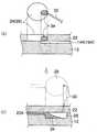
以下、添付図面に従って、本発明に係る科学現象の評価装置及びその製造方法の好ましい実施の形態について詳説する。図1は、本発明に係る科学現象の評価装置である理科実験教材10の構成を説明する平面図である。図2及び図3は、図1の部分拡大断面図等であり、図2は、第1液溜め部24(図1の左上部点線内)を示し、図3は、第3液溜め部28(図1の右下部点線内)を示す。 DESCRIPTION OF THE PREFERRED EMBODIMENTS Preferred embodiments of a scientific phenomenon evaluation apparatus and a manufacturing method thereof according to the present invention will be described below in detail with reference to the accompanying drawings. FIG. 1 is a plan view for explaining the configuration of a science experiment teaching
すなわち、理科実験教材10は、板状体の表面に断面積が1mm2以下の長溝(14、16及び20)が形成されている基板12と、この基板12の表面に密着固定され、長溝を覆うことにより基板12に微細な流路(14A、16A及び20A)を形成する透明な覆い板22とより構成される。That is, the science experiment teaching
上記の長溝(14、16及び20)により形成される微細な流路は、合流点18で合流する略同一長さの第1の流路14A及び第2の流路16Aと、この第1の流路14A及び第2の流路16Aと更に合流点18で合流する第3の流路20Aよりなる。 The fine flow path formed by the long grooves (14, 16 and 20) includes a
また、第1の流路14Aの他端は、覆い板22に形成された円柱状空洞部である第1液溜め部24と連通しており、第2の流路16Aの他端は、覆い板22に形成された円柱状空洞部である第2液溜め部26と連通しており、第3の流路20Aの他端は、基板12に形成された円柱状空洞部である第3液溜め部28と連通している。 The other end of the
更に、覆い板22の第3液溜め部28に相対する部分には、第3液溜め部28と外気とが連通可能な貫通孔30が形成されている。 Further, a
第1液溜め部24、第2液溜め部26及び第3液溜め部28の容積は、5〜5000mm3であることが好ましい。このような容積にすることにより、マイクロなチャンネルの中で起こる各現象のコントロールが容易に行える。The volumes of the first
基板12及び覆い板22の平面サイズは、特に制限はないが、学校で使用する理科実験教材10の性質上より、携帯できるサイズ、たとえば、80×50mmとすることができる。基板12及び覆い板22の厚さも、特に制限はないが、強度、経済性等より、たとえば、それぞれ5mm程度とすることができる。 The planar sizes of the
基板12の材質としては、特に制限はないが、後述する製造方法を容易にする点より、樹脂材料、より具体的には、ポリ・ジメチル・スルホキシド(PDMS)、ポリ・メチル・メタアクリレート(PMMA)、ポリ塩化ビニル(PVC)、紫外線硬化樹脂、ポリカーボネート(PC)等が好ましく使用できる。 Although there is no restriction | limiting in particular as a material of the board |
基板12の表面に形成する長溝(14、16及び20)の断面積としては、既述のように、1mm2以下が好ましく、0.0025〜0.64mm2がより好ましく、0.01〜0.25mm2が最も好ましい。この長溝(14、16及び20)の断面形状は、特に制限はなく、矩形(正方形、長方形)、台形、V形、半円形等、各種の形状が採用できる。The cross-sectional area of the elongated groove is formed on the surface of the substrate 12 (14, 16 and 20), as described above, preferably 1 mm2 or less, more preferably 0.0025~0.64mm2, 0.01~0 .25 mm2 is most preferred. The cross-sectional shape of the long grooves (14, 16 and 20) is not particularly limited, and various shapes such as a rectangle (square, rectangle), a trapezoid, a V shape, and a semicircle can be adopted.
覆い板22の材質としては、特に制限はないが、流路内の科学現象を視覚により認識可能とすることより、透明であることが好ましい。このような材料として、各種樹脂板、より具体的には、ポリジメチルスルホキシド(PDMS)、ポリメチルメタアクリレート(PMMA)、ポリ塩化ビニル(PVC)、紫外線硬化樹脂、ポリカーボネート(PC)等、各種樹脂膜、より具体的には、ポリエチレンテレフタレート(PET)、ポリエチレンナフタレート(PEN)、トリアセチルセルロース(TAC)等、各種ガラス(ソーダライムガラス、硼珪酸ガラス等)が採用できる。 The material of the
この覆い板22は、表面及び裏面が平坦な平板であるのが一般的であるが、微細な流路(14A、16A及び20A)に対応する表面を蒲鉾状の凸レンズ状に形成して、拡大した状態で観察ができるような構成とすることも可能である。 The
なお、覆い板22が不透明であり、基板12を透明とする構成も採用できる。 A configuration in which the
また、後述する、基板12と覆い板22との密着固定方法の際に、材料の変形量が基板12と覆い板22との密着に大きく影響することより、基板12及び覆い板22を加熱による変形量が大きい流延した材料とすることも好ましい。ただし、流延方向により伸縮率が異なることより、積層する際には流延方向を揃えることが必要である。 In addition, in the method of closely fixing the
基板12の表面(長溝が形成される面)及び覆い板22の裏面(基板12に密着する面)は、流路(14A、16A及び20A)の形成、及び液漏れの防止等の点より、十分な平坦性を確保できていることが好ましい。 The surface of the substrate 12 (the surface on which the long groove is formed) and the back surface of the cover plate 22 (the surface that is in close contact with the substrate 12) are formed from the viewpoints of forming the flow paths (14A, 16A, and 20A) and preventing liquid leakage. It is preferable to ensure sufficient flatness.
次に、基板12の形成方法について説明する。先ず、基板12の長溝(14、16及び20)の反転形状が表面に形成されている反転型板を準備する。この反転型板の表面には、更に第3液溜め部28の反転形状を形成しておく必要がある。この反転型板の製造方法としては、マシニングセンタ等による機械加工、放電加工、超音波加工、フォトエッチング加工等、公知の各種加工方法が採用できる。 Next, a method for forming the
次いで、この反転型板の表面に剥離剤を塗布する。この剥離剤としては、基板12となる樹脂材の種類、加工条件(温度等)等に応じて適宜のものが採用できる。 Next, a release agent is applied to the surface of the reversal template. As this release agent, an appropriate one can be adopted according to the type of the resin material to be the
次いで、反転型板の表面に樹脂材を塗布し、この樹脂材を硬化させる。樹脂材が、たとえば紫外線硬化樹脂である場合には、塗布後の樹脂材に紫外線を照射して硬化させる。樹脂材が、たとえばポリ塩化ビニル(PVC)のような熱可塑性樹脂である場合には、反転型板の表面に樹脂材を当ててホットプレス機により熱転写成形を行う。 Next, a resin material is applied to the surface of the inversion mold plate, and the resin material is cured. When the resin material is, for example, an ultraviolet curable resin, the resin material after application is irradiated with ultraviolet rays and cured. When the resin material is a thermoplastic resin such as polyvinyl chloride (PVC), for example, the resin material is applied to the surface of the reversal mold plate, and thermal transfer molding is performed by a hot press machine.
そして、硬化後の樹脂材を反転型板より剥離する。 And the resin material after hardening is peeled from an inversion type | mold board.
このような方法によれば、長溝が精度よく、かつ、安価に形成でき、評価装置を安価にできる。 According to such a method, the long groove can be formed accurately and inexpensively, and the evaluation apparatus can be inexpensively formed.
次に、本発明の特徴部分である、基板12と覆い板22との密着固定方法について説明する。 Next, a method for tightly fixing the
最初に、基板12と覆い板22とを洗浄する。洗浄方法としては、洗浄機による自動洗浄、手洗浄等、公知の各種洗浄方法が採用できる。たとえば、平面サイズが80×50mmで板厚が5mmの基板12及び覆い板22の場合、中性洗剤とスポンジを使用した手動のスクラブ洗浄が好ましく採用できる。 First, the
次工程である乾燥工程において、乾き跡が生じるのを避ける場合には、洗浄後にエアナイフ、乾燥エアブロー等による水切りを行うことが好ましい。 In the drying process, which is the next process, in order to avoid the occurrence of dry marks, it is preferable to drain water with an air knife, a dry air blow or the like after the cleaning.
次いで、乾燥工程を実施する。この工程においては、基板12及び覆い板22を、0.05気圧以下の真空度にした状態で、ガラス転移点Tg未満の温度に加熱することが好ましい。このような状態を実現できる装置であれば、公知の各種装置が適用できるが、たとえば、真空オーブンが好ましく使用できる。 Next, a drying step is performed. In this step, it is preferable that the
このような真空オーブン内において、基板12及び覆い板22を治具等を使用して直立させる保持状態とすることが、真空オーブンの内容積の利用効率からも、基板12及び覆い板22の乾燥状態の点からも好ましい。 In such a vacuum oven, when the
真空オーブン内における雰囲気温度及び処理時間は、基板12及び覆い板22の材質等により異なるが、たとえば、基板12及び覆い板22がポリ・メチル・メタアクリレートである場合には、雰囲気温度を90〜100°Cとでき、処理時間を10時間とできる。 The atmospheric temperature and the processing time in the vacuum oven vary depending on the material of the
乾燥工程に続き、積層工程を実施する。この積層工程において、基板12と覆い板22とを積層する。この作業は、クリーンベンチやクリーンルーム内において、クラス100以下のクリーン度のもとで行うことが、理科実験教材10の品質の点で好ましい。積層後には、基板12と覆い板22の端面の一部に接着され両者を繋ぐ耐熱粘着テープを使用して、基板12と覆い板22との積層体を仮止めすることが好ましい。この仮止めは、端面の2辺又は4辺に行うことが好ましい。 Following the drying process, a lamination process is performed. In this lamination process, the
積層工程に続き、密着工程を実施する。この密着工程において使用する装置(設備)としては、基板12と覆い板22との積層体を、これらのガラス転移点Tg以上の温度に加熱しながら、加圧して密着固定させることができれば、公知の各種装置(設備)、たとえばホットプレス機が使用できる。 Following the lamination process, an adhesion process is performed. As an apparatus (equipment) used in this adhesion process, if the laminated body of the board |
ここでは、簡便な設備として、オーブンと錘(デッドウェイト)を使用した構成により説明する。 Here, as a simple facility, a configuration using an oven and a weight (dead weight) will be described.
密着工程において、先ず、基板12と覆い板22との積層体の上下面に定盤を当て、この定盤で積層体をサンドイッチする。この定盤として、基板12及び覆い板22と略同一平面サイズで厚さが5mmのフロートガラスが好ましく使用できる。 In the adhesion step, first, a surface plate is applied to the upper and lower surfaces of the laminate of the
この定盤を使用する理由は、荷重が基板12と覆い板22との積層体の上下面に均一に印加できるようにするためである。すなわち、オーブン内の積層体を載置する部分は、金網の棚となっているのが一般的であり、これでは荷重が均一に印加されない。また、錘(デッドウェイト)は金属製であるのが一般的であるが、この錘の下面を平坦度よく加工した場合、コストアップとなる。 The reason for using this surface plate is to allow a load to be uniformly applied to the upper and lower surfaces of the laminate of the
これに対し、フロートガラスは比較的安価である。特に、厚さが5mm前後のフロートガラスは、平坦度がよく、また剛性も充分であり、上下面よりの荷重を受け、これを積層体に均一に印加できる。 In contrast, float glass is relatively inexpensive. In particular, the float glass having a thickness of about 5 mm has good flatness and sufficient rigidity, and can receive a load from the upper and lower surfaces and apply it uniformly to the laminate.
定盤でサンドイッチした積層体を、オーブン内の棚(積層体を載置する部分)に載置した後、この上に錘(デッドウェイト)を載置する。 After the laminated body sandwiched by the surface plates is placed on a shelf (a part on which the laminated body is placed) in the oven, a weight (dead weight) is placed thereon.
この錘をステンレス鋼製とし、この錘の平面サイズを、基板12及び覆い板22と略同一サイズとした場合、たとえば積層体を10kPaに加圧するには、錘の厚さを約130mmにすればよい。 When this weight is made of stainless steel and the weight has a plane size substantially the same as that of the
密着工程において、基板12と覆い板22とを密着固定させるための条件は、基板12及び覆い板22の材質により異なるが、基板12及び覆い板22がポリ・メチル・メタアクリレートである場合、雰囲気温度を130〜140°Cとしたとき、加圧力を10〜15kPaとでき、雰囲気温度を120〜130°Cとしたとき、加圧力を15〜20kPaとできる。 In the adhesion process, the conditions for tightly fixing the
また、処理時間も重要な要素であり、雰囲気温度と加圧力及び経済性(スループット、歩留り等)を考慮して最適な条件を検討するのが好ましい。 Further, the processing time is an important factor, and it is preferable to examine the optimum conditions in consideration of the atmospheric temperature, the applied pressure, and the economy (throughput, yield, etc.).
密着工程において重要なことは、雰囲気温度を高く設定し過ぎたり、処理時間を長く設定し過ぎたりして、長溝の断面形状を損うことがないように管理することであり、雰囲気温度を低く設定し過ぎたり、処理時間を短く設定し過ぎたりして、基板12と覆い板22とを密着固定できない(液漏れを生じたり、密着面に気泡が残存したりする)ことがないように管理することである。 What is important in the adhesion process is to manage the atmosphere so as not to damage the cross-sectional shape of the long groove by setting the atmosphere temperature too high or setting the processing time too long. Management is performed so as not to set the
なお、密着工程において、オーブンと錘を使用した構成による場合、オーブン内部の昇温速度は、0.5〜10°C/分が好ましく、1〜5°C/分がより好ましい。また、降温速度は、歪による密着不良を避ける意味で、0.1〜1°C/分が好ましく、0.3〜0.5°C/分がより好ましい。 In addition, in the contact | adherence process, when it is based on the structure which uses oven and a weight, 0.5-10 degreeC / min is preferable and, as for the temperature increase rate inside an oven, 1-5 degreeC / min is more preferable. Moreover, the temperature decreasing rate is preferably 0.1 to 1 ° C / min, more preferably 0.3 to 0.5 ° C / min, in order to avoid poor adhesion due to strain.
次に、本発明に係る理科実験教材10の使用方法について説明する。理科実験教材10としては、以下の1)〜7)の部材をセットとして提供する必要がある。 Next, a method for using the science
1)基板12と覆い板22との密着積層体
2)サンプル液用スポイト
(テスト目的に応じて、必要なサンプル液(試薬)を、第1液溜め部24及び第2液溜め部26に供給するために使用する。薬品ごとに専用でも、1つを洗浄して使いまわしても構わない)。1) Adhesive laminate of
3)サンプル液出入り口封止用テープ
(サンプル液供給用ホールである第1液溜め部24及び第2液溜め部26の蓋となる。サンプル液をピペットで第1液溜め部24及び第2液溜め部26に供給後、蓋をするためのものである。また、第3液溜め部28の蓋として使用することもできる)。3) Sample liquid inlet / outlet sealing tape (covers the first
4)針
(サンプル液を供給する場合、又は、回収する場合、液体が送受液される時に液体の変動分の空気を第1液溜め部24及び第2液溜め部26に入れるため、必要に応じてテープに孔を開けるためのものである)。4) Needle (When supplying or collecting the sample liquid, it is necessary to supply air for the fluctuation of the liquid into the first
5)送液手段
(第1液溜め部24及び第2液溜め部26にテープで蓋をした状態で、この第1液溜め部24及び第2液溜め部に熱を加えると(指先をテープに当て、体温で加熱等すると)、この第1液溜め部24及び第2液溜め部2内の液体、及び/又は、気体が体積膨張する。この現象を利用した送液方法である。5) Liquid feeding means (When the first
第1液溜め部24及び第2液溜め部26内をポンプの原理を利用した方法で加圧して、内部の液体を送り出す方法、などが可能である。 A method in which the inside of the first
この場合、前述4)の針を用いて、第3液溜め部28にテープが貼られている場合には、これに小さな孔を開ける。 In this case, when the tape is affixed to the third
また、第3液溜め部28側をポンプなどを用いて減圧したり、第3液溜め部28上に氷塊を置き、第3液溜め部28内部の気体を収縮させて減圧したりすることにより、第1液溜め部24及び第2液溜め部26内にあるサンプル液を流路(14A、16A及び20A)に入れる場合には、第1液溜め部24及び第2液溜め部のテープ蓋に前述4)の針を用いて小さな孔を開けることにより送液を可能にする)。 Further, the third
6)試験用サンプル液(試薬)
(本科学実験を行うためのテスト試薬として目的に合った必要な薬品を試薬容器に入れて供給する。サンプル液としては、たとえば、色素、又は、顔料などに代表される着色性液体と水など透明液体とが挙げられる)。6) Test sample solution (reagent)
(A necessary chemical suitable for the purpose as a test reagent for conducting this scientific experiment is supplied in a reagent container. Sample liquids include, for example, coloring liquids such as pigments or pigments, and water. Transparent liquid).
7)実験解説書
(本セットで行う実験の目的、現象の説明、応用用途など、このセットで学習できる事象の解説書を必要に応じて添付する)。7) Explanatory notes (If necessary, explanations of the events that can be learned with this set, such as the purpose of the experiment, explanation of phenomena, and application uses)
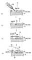
このセットを使用した実験の詳細については、以下に詳述する。図4及び図5は、実験方法の手順を示す断面図である。このうち、図4は、第1液溜め部24及び第2液溜め部26における時系列的な手順を示す。一方、図5(a)は、第1液溜め部24及び第2液溜め部26にサンプル液を供給した実験開始の状態を示し、図5(b)は、第3液溜め部28にサンプル液が到達した実験終了の状態を示す。 Details of experiments using this set are detailed below. 4 and 5 are cross-sectional views showing the procedure of the experimental method. Among these, FIG. 4 shows a time-series procedure in the first
図4(a)に示されるように、サンプル液用スポイト32により第1液溜め部24(又は第2液溜め部26)に所定量のサンプル液34を供給する。このサンプル液34は、図4(b)及び図5(a)に示されるように、第1液溜め部24(又は第2液溜め部26)内の流路14A(又は16A)と連通する部分を塞ぐように供給される。 As shown in FIG. 4A, a predetermined amount of
次いで、図4(c)に示されるように、サンプル液出入り口封止用のテープ36により第1液溜め部24(又は第2液溜め部26)に蓋をする。このテープ36は、片面(図では下面)に粘着材がコートされているものであり、これにより、第1液溜め部24(又は第2液溜め部26)が外気と遮断される。 Next, as shown in FIG. 4C, the first liquid reservoir 24 (or the second liquid reservoir 26) is covered with the sample liquid inlet /
次いで、図4(d)に示されるように、テープ36の上に指先38を接触させる。これにより、第1液溜め部24(又は第2液溜め部26)に送液手段が形成される。この送液手段は、既述したように、指先38の熱により第1液溜め部24(又は第2液溜め部26)内の気体が体積膨張し、サンプル液34を流路14A(又は16A)に送り込むことによりなされる。 Next, as shown in FIG. 4D, the
また、図4(d)に示される同様の構成において、この送液手段が、指先38でテープ36を押して下方に撓ませ、第1液溜め部24(又は第2液溜め部26)の容積を減少させることにより、サンプル液34を流路14A(又は16A)に送り込むことによりなされるのであってもよい。 Further, in the same configuration shown in FIG. 4 (d), the liquid feeding means pushes the
以上に説明した送液手段により、図5(b)に示されるように、サンプル液34が第3液溜め部28に到達し、実験が終了する。この際、図1の第1液溜め部24及び第2液溜め部26より、それぞれ送液手段により、同時にサンプル液34を流路14A及び流路16Aに送り込むことにより、サンプル液34が合流点18で合流する様が観察できる。 As shown in FIG. 5B, the liquid feeding means described above causes the
特に、第1液溜め部24と第2液溜め部26に供給するサンプル液34の色を違えておくことにより、サンプル液34が合流点18で合流する様が観察しやすい。たとえば、第1液溜め部24に着色したサンプル液34を供給し、第2液溜め部26に無色透明なサンプル液34を供給する態様である。 In particular, the
実験者は、このようにして流れるサンプル液34の合流点18以降の流路20Aを観察することにより、マイクロチャンネル内を流れる着色液側から色素、又は、顔料など着色性分子が透明液中に向かって拡散して行く現象を確認することができる。 The experimenter observes the
また、第1液溜め部24と第2液溜め部26に供給するサンプル液34の色を違えておくのみならず、粘度を違えておくことにより、サンプル液34が合流点18で合流する様が異なって観察できる。 Further, not only the color of the
なお、これらの現象をより観察しやすくするために、虫眼鏡、拡大鏡などを使用することもできる。また、既述のように、流路20Aの部分の覆い板22に拡大鏡機能(レンズ機能)を持たせることもできる。 In order to make it easier to observe these phenomena, a magnifying glass, a magnifying glass, or the like can be used. Further, as described above, the
以上に説明した理科実験教材10によれば、マイクロな世界での科学実験を子供たちに楽しく夢を持って行って貰うために、重要な部分をできるだけ簡素化して、安価にでき、かつ、実験は高精度に行える。 According to the science
特に、化学反応の元になる分子の拡散現象等を定性的に観察する場合、実験精度を向上させるために、複数の液が少なくとも同じ条件で流路内を流れることが非常に重要であるが、この要求に十分に答えられる。すなわち、非常に簡便、安価な手段で比較的精度よい実験が可能である。また、マイクロな世界での実験のため、色素、又は、顔料などに代表される化学薬品の使用量も非常に少なくて済み、環境負荷が大幅に軽減できる。 In particular, when qualitatively observing the diffusion phenomenon of molecules that cause chemical reactions, it is very important that a plurality of liquids flow in the flow path at least under the same conditions in order to improve the experimental accuracy. Can fully answer this request. That is, a relatively accurate experiment can be performed with a very simple and inexpensive means. In addition, because of experiments in the micro world, the amount of chemicals represented by dyes or pigments is very small, and the environmental burden can be greatly reduced.
以上、本発明に係る科学現象の評価装置及びその製造方法の実施形態について説明したが、本発明は上記実施形態に限定されるものではなく、各種の態様が採り得る。 As mentioned above, although embodiment of the evaluation apparatus of the scientific phenomenon concerning this invention and its manufacturing method was described, this invention is not limited to the said embodiment, Various aspects can be taken.
たとえば、製造方法の実施形態において、密着工程は大気圧状態で行われているが、真空状態(又は減圧状態)で行うこともできる。このように減圧下で密着工程が実施され、その後、大気圧状態のもとに積層体が取り出された場合、密着工程の際に基板12と覆い板22との間に生じていた空隙が、積層体が大気圧を受けることにより消失してしまい、泡欠点となることはない。 For example, in the embodiment of the manufacturing method, the adhesion process is performed in an atmospheric pressure state, but may be performed in a vacuum state (or a reduced pressure state). In this way, when the adhesion process is performed under reduced pressure, and then the laminated body is taken out under atmospheric pressure, the gap generated between the
その意味で、密着工程において、基板12と覆い板22との間の脱気が促進できるように、密着工程の初期には積層体に荷重が付加されない構成を採用し(たとえば、錘を他の手段で吊り上げておく)、所定時間が経過し、真空度が維持できるようになった状態で、積層体に荷重が付加される構成(たとえば、錘の吊り上げを解除する)を採用することがより好ましい。 In that sense, a structure in which no load is applied to the laminated body at the initial stage of the adhesion process is adopted so that deaeration between the
また、本実施形態において、密着工程は、オーブンと錘を使用した構成が採用されているが、生産数量が増加した場合には、多段式のホットプレス機を使用する構成が採用できる。多段式のホットプレス機は1バッチで大量の処理が可能であり、加熱もボイラーを使用でき、工業的生産には好ましいからである。 In the present embodiment, a configuration using an oven and a weight is employed for the contact process. However, when the production quantity increases, a configuration using a multistage hot press machine can be employed. This is because a multi-stage hot press machine can process a large amount in one batch and can use a boiler for heating, which is preferable for industrial production.
また、基板12と覆い板22との密着積層体の構成において、本実施形態では、2種類のサンプル液34が合流点18で合流し、色素、又は、顔料など着色性分子が透明液中に向かって拡散して行く現象を観察できる実験教材の例を説明したが、これ以外の各種の実験教材としても適用できる。 In the configuration of the close-contact laminate of the
また、本実施形態では、第1液溜め部24及び第2液溜め部26を覆い板22に形成し、第3液溜め部28を基板12に形成しているが、これ以外の態様、たとえば、全ての液溜め部を覆い板22に形成する態様も採用できる。 In the present embodiment, the first
また、本実施形態では、流路と液溜め部を3組設ける構成としたが、4組以上設ける構成も採用できる。 In the present embodiment, three sets of flow paths and liquid reservoirs are provided. However, a configuration in which four or more sets are provided can also be employed.
更に、サンプル液(試薬)を液溜め部(24、26等)に供給するために、サンプル液用スポイト32が使用されているが、これに代えて、同様の機能を有する注射器、マイクロシリンジ等を使用することもできる。理科実験教材としては、一般的には、安価なスポイトを使用するのが望ましいが、テスト目的に応じては、上記のように同様の機能を有するものが好ましいこともある。 Furthermore, in order to supply the sample liquid (reagent) to the liquid reservoir (24, 26, etc.), the
10…理科実験教材、12…基板、14、16、20…長溝、14A…第1の流路、16A…第2の流路、18…合流点、20A…第3の流路、22…覆い板、24…第1液溜め部、26…第2液溜め部、28…第3液溜め部、30…貫通孔、32…サンプル液用スポイト、34…サンプル液、36…テープ、38…指先 DESCRIPTION OF
Claims (6)
Translated fromJapanese前記基板及び覆い板を、該基板及び覆い板を形成する樹脂材のガラス転移点Tg未満の温度に加熱して乾燥させる乾燥工程と、
前記基板と覆い板とを積層する積層工程と、
積層された前記基板と覆い板とを該基板及び覆い板を形成する樹脂材のガラス転移点Tg以上の温度に加熱しながら密着固定させる密着工程と、を備えることを特徴とする科学現象の評価装置の製造方法。A substrate in which a long groove having a cross-sectional area of 1 mm2 or less is formed on the surface of the plate-like body, and a cover plate that is disposed on the surface of the substrate and forms a fine flow path in the substrate by covering the long groove. And the substrate and the cover plate are closely fixed without using an adhesive, the substrateand the cover plateare formed of a resin material, andat least one of thesubstrate and the cover plate is made of a transparent resin material. , A scientific phenomenon evaluation device manufacturing method in which the scientific phenomenon in the flow path can be visually recognized,
Saidsubstrate and cover plate, a drying step of drying by heating to a temperature below the glass transition point Tg of the resin materialforming the substrate and cover plate,
A laminating step of laminating the substrate and the cover plate;
An adhesion step of fixing thesubstrate and the cover plate while being heated to a temperature equal to or higher than the glass transition point Tg ofthe resin materialforming the substrate and the cover plate. Device manufacturing method.
Priority Applications (4)
| Application Number | Priority Date | Filing Date | Title |
|---|---|---|---|
| JP2004163234AJP4482929B2 (en) | 2004-06-01 | 2004-06-01 | Manufacturing method of scientific phenomenon evaluation device |
| US11/141,319US20050263567A1 (en) | 2004-06-01 | 2005-06-01 | Scientific phenomena evaluation device and manufacturing method of the same |
| EP05011796AEP1603100A1 (en) | 2004-06-01 | 2005-06-01 | Scientific phenomena evaluation device and manufacturing method of the same |
| US11/491,913US20060254714A1 (en) | 2004-06-01 | 2006-07-25 | Manufacturing method of scientific phenomena evaluation device |
Applications Claiming Priority (1)
| Application Number | Priority Date | Filing Date | Title |
|---|---|---|---|
| JP2004163234AJP4482929B2 (en) | 2004-06-01 | 2004-06-01 | Manufacturing method of scientific phenomenon evaluation device |
Publications (2)
| Publication Number | Publication Date |
|---|---|
| JP2005345609A JP2005345609A (en) | 2005-12-15 |
| JP4482929B2true JP4482929B2 (en) | 2010-06-16 |
Family
ID=34937126
Family Applications (1)
| Application Number | Title | Priority Date | Filing Date |
|---|---|---|---|
| JP2004163234AExpired - Fee RelatedJP4482929B2 (en) | 2004-06-01 | 2004-06-01 | Manufacturing method of scientific phenomenon evaluation device |
Country Status (3)
| Country | Link |
|---|---|
| US (2) | US20050263567A1 (en) |
| EP (1) | EP1603100A1 (en) |
| JP (1) | JP4482929B2 (en) |
Families Citing this family (1)
| Publication number | Priority date | Publication date | Assignee | Title |
|---|---|---|---|---|
| JP2011053091A (en)* | 2009-09-02 | 2011-03-17 | Alps Electric Co Ltd | Bonding member and method of manufacturing the same |
Family Cites Families (26)
| Publication number | Priority date | Publication date | Assignee | Title |
|---|---|---|---|---|
| US4034493A (en)* | 1975-10-29 | 1977-07-12 | Wham-O Mfg. Co. | Fluid novelty device |
| US5242307A (en)* | 1992-07-13 | 1993-09-07 | Reinbold Paul J | Teaching tank |
| JPH10170495A (en)* | 1996-12-12 | 1998-06-26 | Tokico Ltd | Analysis equipment |
| US6632619B1 (en)* | 1997-05-16 | 2003-10-14 | The Governors Of The University Of Alberta | Microfluidic system and methods of use |
| US5842787A (en)* | 1997-10-09 | 1998-12-01 | Caliper Technologies Corporation | Microfluidic systems incorporating varied channel dimensions |
| US6100541A (en)* | 1998-02-24 | 2000-08-08 | Caliper Technologies Corporation | Microfluidic devices and systems incorporating integrated optical elements |
| RU2195653C2 (en)* | 1998-06-12 | 2002-12-27 | Асахи Касеи Кабусики Кайся | Analyser |
| JP3884877B2 (en)* | 1999-02-19 | 2007-02-21 | 株式会社東洋製作所 | Natural phenomenon observation device by temperature change of water |
| JP2000298109A (en)* | 1999-04-13 | 2000-10-24 | Kanagawa Acad Of Sci & Technol | Micro channel structure |
| JP2000298079A (en)* | 1999-04-13 | 2000-10-24 | Kanagawa Acad Of Sci & Technol | Molecular transport extraction method |
| WO2001007159A2 (en)* | 1999-07-28 | 2001-02-01 | Genset | Integration of biochemical protocols in a continuous flow microfluidic device |
| TW517154B (en)* | 1999-08-11 | 2003-01-11 | Asahi Chemical Ind | Analyzing cartridge and liquid feed control device |
| US6254396B1 (en)* | 1999-09-28 | 2001-07-03 | Delta Education, Inc. | Teaching device for science experiments |
| JP2001165939A (en)* | 1999-12-10 | 2001-06-22 | Asahi Kasei Corp | Capillary analyzer |
| DE20005052U1 (en)* | 2000-03-20 | 2000-07-20 | Höller, Stefan, 23552 Lübeck | Device for displaying chemical and / or physical tests |
| JP2002139419A (en)* | 2000-10-31 | 2002-05-17 | Nippon Sheet Glass Co Ltd | Micropassage element and production method thereof |
| US6443179B1 (en)* | 2001-02-21 | 2002-09-03 | Sandia Corporation | Packaging of electro-microfluidic devices |
| US6919046B2 (en)* | 2001-06-07 | 2005-07-19 | Nanostream, Inc. | Microfluidic analytical devices and methods |
| EP1453758A2 (en)* | 2001-12-06 | 2004-09-08 | Nanostream, Inc. | Adhesiveless microfluidic device fabrication |
| JP2003240755A (en)* | 2002-01-31 | 2003-08-27 | Ecole Polytechnique Federale De Lausanne | Microchip made of transparent hydrocarbon polymer |
| JP4083452B2 (en)* | 2002-03-28 | 2008-04-30 | 旭化成株式会社 | Valve mechanism |
| JP2003302360A (en)* | 2002-04-12 | 2003-10-24 | Nippon Sheet Glass Co Ltd | Chip member of micro chemical system |
| JP3605102B2 (en)* | 2002-07-18 | 2004-12-22 | キヤノン株式会社 | Liquid mixing device |
| JP2004053559A (en)* | 2002-07-24 | 2004-02-19 | Nippon Sheet Glass Co Ltd | Manufacturing method of chip member for micro-chemical system and chip member for micro-chemical system manufactured by the method |
| US20040101657A1 (en)* | 2002-08-19 | 2004-05-27 | Moles Donald R. | Method of microfluidic construction using composite polymer films |
| EP1566784A1 (en)* | 2004-02-20 | 2005-08-24 | Fuji Photo Film Co., Ltd. | Evaluation apparatus of scientific phenomena, educational tool for scientific experiments and method of manufacturing the same |
- 2004
- 2004-06-01JPJP2004163234Apatent/JP4482929B2/ennot_activeExpired - Fee Related
- 2005
- 2005-06-01USUS11/141,319patent/US20050263567A1/ennot_activeAbandoned
- 2005-06-01EPEP05011796Apatent/EP1603100A1/ennot_activeWithdrawn
- 2006
- 2006-07-25USUS11/491,913patent/US20060254714A1/ennot_activeAbandoned
Also Published As
| Publication number | Publication date |
|---|---|
| US20060254714A1 (en) | 2006-11-16 |
| JP2005345609A (en) | 2005-12-15 |
| EP1603100A1 (en) | 2005-12-07 |
| US20050263567A1 (en) | 2005-12-01 |
Similar Documents
| Publication | Publication Date | Title |
|---|---|---|
| CN107305214A (en) | A kind of preparation method of hard micro-fluid chip | |
| CN105170206A (en) | Micro-fluidic chip achieving multi-index detection | |
| US11759782B2 (en) | Microfluidic chip and a method for the manufacture of a microfluidic chip | |
| Kalkandjiev et al. | Microfluidics in silicon/polymer technology as a cost-efficient alternative to silicon/glass | |
| CN110227566A (en) | A kind of PDMS Micro-fluidic chip die clone method | |
| CN106423319B (en) | A kind of sample analysis chip and its application method | |
| CN205127987U (en) | Micro -fluidic chip for multi -index detection | |
| CN105344394B (en) | High-precision micro liquid equivalent flow distributor | |
| CN208591844U (en) | Micro-fluidic chip, micro-fluidic chip encapsulation encapsulation accessory | |
| JP4482929B2 (en) | Manufacturing method of scientific phenomenon evaluation device | |
| CN100425983C (en) | Laser induced fluorescence and light absorption bifunction detecting microflow controlled electrophoresis ehip | |
| JP2007268486A (en) | Microdevice fluid control method and mechanism, and scientific phenomenon evaluation apparatus using the same | |
| US7344378B2 (en) | Scientific phenomena evaluation device, educational tool for scientific experiments and manufacturing method of the device and tool | |
| US20070071640A1 (en) | Scientific phenomenon evaluation device, pH measurement experimental device and manufacturing method of the device | |
| KR101053772B1 (en) | Molding module for manufacturing a microfluidic chip mold, a method for manufacturing a microfluidic chip mold using the same, and a microfluidic chip mold manufactured thereby | |
| CN106563516B (en) | A kind of teaching preparation method of microchip | |
| US7316569B2 (en) | Evaluation apparatus of scientific phenomena, educational tool for scientific experiments and method of manufacturing the same | |
| JP4392554B2 (en) | Scientific phenomenon evaluation device, science experiment teaching material, and manufacturing method thereof | |
| JPWO2009125757A1 (en) | Microchip and manufacturing method of microchip | |
| JP2005234390A (en) | Evaluation apparatus for scientific phenomenon and teaching material for science experiment, and method for manufacturing same | |
| JP2007093949A (en) | Drawing device | |
| CN108597335A (en) | A kind of preparation method of green multifunctional teaching microchip | |
| US20090305216A1 (en) | Experimental method for scientific phenomenon evaluating apparatus, and scientific phenomenon evaluating apparatus | |
| JP2005234389A (en) | Evaluation apparatus for scientific phenomenon and teaching material for science experiment, and method for manufacturing same | |
| TW558549B (en) | A manufacturing method for chip-type microchannels |
Legal Events
| Date | Code | Title | Description |
|---|---|---|---|
| A711 | Notification of change in applicant | Free format text:JAPANESE INTERMEDIATE CODE: A712 Effective date:20061226 | |
| A621 | Written request for application examination | Free format text:JAPANESE INTERMEDIATE CODE: A621 Effective date:20070216 | |
| A131 | Notification of reasons for refusal | Free format text:JAPANESE INTERMEDIATE CODE: A131 Effective date:20090501 | |
| A521 | Written amendment | Free format text:JAPANESE INTERMEDIATE CODE: A523 Effective date:20090624 | |
| A131 | Notification of reasons for refusal | Free format text:JAPANESE INTERMEDIATE CODE: A131 Effective date:20090916 | |
| A521 | Written amendment | Free format text:JAPANESE INTERMEDIATE CODE: A523 Effective date:20091111 | |
| TRDD | Decision of grant or rejection written | ||
| A01 | Written decision to grant a patent or to grant a registration (utility model) | Free format text:JAPANESE INTERMEDIATE CODE: A01 Effective date:20100301 | |
| A01 | Written decision to grant a patent or to grant a registration (utility model) | Free format text:JAPANESE INTERMEDIATE CODE: A01 | |
| A61 | First payment of annual fees (during grant procedure) | Free format text:JAPANESE INTERMEDIATE CODE: A61 Effective date:20100314 | |
| R150 | Certificate of patent or registration of utility model | Free format text:JAPANESE INTERMEDIATE CODE: R150 | |
| FPAY | Renewal fee payment (event date is renewal date of database) | Free format text:PAYMENT UNTIL: 20130402 Year of fee payment:3 | |
| FPAY | Renewal fee payment (event date is renewal date of database) | Free format text:PAYMENT UNTIL: 20130402 Year of fee payment:3 | |
| FPAY | Renewal fee payment (event date is renewal date of database) | Free format text:PAYMENT UNTIL: 20140402 Year of fee payment:4 | |
| R250 | Receipt of annual fees | Free format text:JAPANESE INTERMEDIATE CODE: R250 | |
| R250 | Receipt of annual fees | Free format text:JAPANESE INTERMEDIATE CODE: R250 | |
| R250 | Receipt of annual fees | Free format text:JAPANESE INTERMEDIATE CODE: R250 | |
| LAPS | Cancellation because of no payment of annual fees |