JP4482318B2 - Puncture needle cartridge - Google Patents
Puncture needle cartridgeDownload PDFInfo
- Publication number
- JP4482318B2 JP4482318B2JP2003416967AJP2003416967AJP4482318B2JP 4482318 B2JP4482318 B2JP 4482318B2JP 2003416967 AJP2003416967 AJP 2003416967AJP 2003416967 AJP2003416967 AJP 2003416967AJP 4482318 B2JP4482318 B2JP 4482318B2
- Authority
- JP
- Japan
- Prior art keywords
- puncture needle
- puncture
- needle
- cartridge
- needles
- Prior art date
- Legal status (The legal status is an assumption and is not a legal conclusion. Google has not performed a legal analysis and makes no representation as to the accuracy of the status listed.)
- Expired - Fee Related
Links
Images


Landscapes
- Measurement Of The Respiration, Hearing Ability, Form, And Blood Characteristics Of Living Organisms (AREA)
Description
Translated fromJapanese本発明は、穿刺針カートリッジ、及び採血用穿刺器具に関し、特に、血糖値を測定する場合などに使用する、複数個の穿刺針から一個ずつ穿刺針を取り出す構成の採血用穿刺器具、および該採血用穿刺器具用の穿刺針カートリッジに関する。 The present invention relates to a puncture needle cartridge and a blood collection puncture device, and more particularly to a blood collection puncture device configured to take out a puncture needle one by one from a plurality of puncture needles used when measuring blood glucose levels, and the like. The present invention relates to a puncture needle cartridge for a puncture device for medical use.
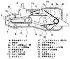
糖尿病の患者さんは、自分自身で血糖値を一日に数回測定している。この測定時に、指先などから少量の血液を採取する必要がある。そのために、図8に示したように、穿刺器具101といわれる装置に使い捨ての穿刺針105を取り付け、その穿刺針105によって、指先や腕などを穿刺し、その穿刺した部位からの出血を測定に用いる。 Diabetes patients themselves measure blood sugar levels several times a day. At the time of this measurement, it is necessary to collect a small amount of blood from the fingertip or the like. For this purpose, as shown in FIG. 8, a
一般的な穿刺器具101は、筒状の本体部分130と、キャップ部分153とから構成されている。上記筒状の本体部分130には、取り付けた穿刺針105を打ち出すための第1のバネ132、打ち出した穿刺針105を後退させるための第2のバネ134、および圧縮された第1のバネ132を解放するための発射ボタン117を有している。 A
使用方法は、上記筒状本体部分130からキャップ153を外し、筒状本体部分130に穿刺針105を装着し、再度キャップ153を筒状本体部分130にかぶせる。そして、第1のバネ132を圧縮して、穿刺動作を可能な状態とし、キャップ153の穿刺部押圧面136を、指先などの穿刺部に当て、発射ボタン117を押すと、穿刺針105が打ち出されて穿刺が行われる。該穿刺が行われた後は、第2のバネ134により、穿刺針105は即座に指先などから後退することになり、この様な上述した動作によって血液を採取することができるものである。ここで、一度使用した穿刺針105を再使用することは衛生面から非常に危険であり、そのため、次の使用時には穿刺針105を交換する必要がある(例えば特許文献1参照。)。
ところで、使用者は、上記のような従来の穿刺器具システム、すなわち、上記のような穿刺針および穿刺動作工程を用いた、手作業による動作段階の多くを面倒だと思っている。このため、使用者は、一度挿入された穿刺針を、穿刺動作および血液採取のために数回使用してしまいがちになる。1本の穿刺針を複数回使用することは、特に穿刺針を2人以上の人物に使用する場合、衛生面の理由から避けなければならない。このような状況は、例えば開業医院、病院において起こり得るが、子供が間違って使用してしまうケースも除外できない。 By the way, the user thinks that many of the operation steps by the manual work using the conventional puncture device system as described above, that is, the puncture needle and the puncture operation process as described above are troublesome. For this reason, the user tends to use the puncture needle once inserted several times for puncture operation and blood collection. The use of a single puncture needle multiple times must be avoided for hygiene reasons, especially when the puncture needle is used on more than one person. Such a situation can occur, for example, in a practicing clinic or a hospital, but it cannot be excluded that a child uses it by mistake.
一方で、穿刺針は1回使い捨て用として製造されているので、複数回使用すれば先端がすぐに鈍くなってしまうため、穿刺針の連続使用は患者にさらに痛みを与える原因となる。さらに、従来技術による穿刺装置、および穿刺針では、穿刺装置への穿刺針の挿入を正確に行えない危険性がある。また、穿刺針、および穿刺装置を誤使用した場合、使用者が誤って怪我をする危険性もある。 On the other hand, since the puncture needle is manufactured once for single use, the tip is quickly dulled if used multiple times, and therefore continuous use of the puncture needle causes further pain to the patient. Furthermore, there is a risk that the puncture device and the puncture needle according to the prior art cannot accurately insert the puncture needle into the puncture device. In addition, when the puncture needle and the puncture device are misused, there is a risk that the user may be injured by mistake.
以上のように、従来技術では穿刺針の交換時に使用済みの穿刺針で指先を怪我する危険性があり、また一日数回測定するため、穿刺針の交換が非常に煩わしいものであった。特に、糖尿病の合併症等により、目の不自由な患者さんにとっては大きな問題であった。 As described above, in the prior art, there is a risk of injuring the fingertip with a used puncture needle when replacing the puncture needle, and since the measurement is performed several times a day, replacement of the puncture needle is very troublesome. In particular, it was a big problem for blind people due to complications of diabetes.
上記課題を解決するために、本発明にかかる穿刺針カートリッジ、及び採血用穿刺器具は、穿刺針を複数個一体的に形成してなる穿刺針カートリッジを構成し、この穿刺針カートリッジから1つ1つの穿刺針を、順次穿刺器具に装着することによって、穿刺針を所定の穿刺位置にセット可能とするとともに、該穿刺針の入換えを容易に行えるようにしたものである。また、穿刺時に同じ個所を複数回穿刺することが無いようにしたものである。 In order to solve the above problems, a puncture needle cartridge and a blood sampling puncture device according to the present invention constitute a puncture needle cartridge in which a plurality of puncture needles are integrally formed, and each of the puncture needle cartridges is one by one. By sequentially attaching two puncture needles to a puncture device, the puncture needle can be set at a predetermined puncture position and the puncture needle can be easily replaced. In addition, the same location is not punctured multiple times during puncture.
すなわち、請求項1にかかる発明の穿刺針カートリッジは、各々針を樹脂で一体に成形してなる複数の穿刺針が、該穿刺針の先端側が1つの基台に一体的に連続するように設けられ、前記各穿刺針の後端側は、開放して終端されており、前記複数の穿刺針は、各々が独立しており、かつ、該各穿刺針は、前記複数の穿刺針が一平面内に並列配置されてなる状態から、該1つの穿刺針を該平面と交差する状態に倒す、または起こすことができるよう、その各先端側が可撓性を持って前記基台に連結されていることを特徴とするものであり、これにより、生体の表面を穿刺針を用いて穿刺を行う場合において、穿刺毎に穿刺針を露出させた状態で操作をすることもなく、穿刺針を連続的に穿刺器具本体に装填することが可能なものが得られ、また、各穿刺針を一本ずつ起すことで、隣接する穿刺針が邪魔にならずに、穿刺針を一つずつ所定の位置へ容易にセットできるものが得られる。That is, the puncture needle cartridge of the invention according to
請求項2にかかる発明の穿刺針カートリッジは、請求項1に記載の穿刺針カートリッジにおいて、前記各穿刺針は、これを前記基台から切り離したとき該穿刺針の針部が露出し、前記穿刺針を覆っていたキャップ部分は、前記基台に一体的に連結された状態で残ることを特徴とするものであり、これにより、穿刺針を除去した後に隣接する穿刺針キャップ部分が全て一体的になっていることで、廃棄物となるキャップの分散を防止することができ、かつ、廃棄物容量をコンパクトにできるものが得られる。A puncture needle cartridge according to asecond aspect of the present invention is the puncture needle cartridge according to thefirst aspect , wherein each puncture needle is exposed when the puncture needle is separated from the base, and the puncture needle cartridge is exposed. The cap portion covering the needle remains in a state of being integrally connected to the base, whereby all the adjacent puncture needle cap portions are integrated after the puncture needle is removed. As a result, it is possible to prevent the cap that becomes waste from being dispersed and to reduce the waste volume.
請求項3にかかる発明の穿刺針カートリッジは、請求項1または2に記載の穿刺針カートリッジにおいて、前記基台は、前記複数の穿刺針を一平面内に配置している側面と垂直の側面に、使用済み穿刺針把持機構を有することを特徴とするものであり、これにより、使用済み穿刺針を、容易に、かつ正確に、廃棄処理をすることができる。A puncture needle cartridge according to athird aspect of the present invention is the puncture needle cartridge according to thefirst or second aspect , wherein the base has a side surface perpendicular to a side surface on which the plurality of puncture needles are arranged in one plane., which is characterized by having ause for spent needle gripping mechanism, thereby, the used puncture needle, easily, and accurately, it is possible to discard processing.
請求項4にかかる発明の穿刺針カートリッジは、請求項3に記載の穿刺針カートリッジにおいて、前記使用済み穿刺針把持機構は、該把持機構により把持された使用済み穿刺針を、外方より前記穿刺器具により保持された使用済み穿刺針により押圧すると、前記把持機構により把持されていた1回前の使用済み穿刺針が、該穿刺針カートリッジの廃棄ボックス部内に落下され、廃棄されるものであることを特徴とするものであり、これにより、穿刺毎に穿刺針を露出させた状態で該穿刺針の操作をすることもなく、穿刺針を連続的に穿刺器具本体に装填することが可能となるものである。Puncture needle cartridge of the invention according to
請求項5の発明にかかる穿刺針カートリッジによれば、請求項1ないし4のいずれかに記載の穿刺針カートリッジにおいて、前記穿刺針は、その中央部に、穿刺器具内の穿刺針保持ロッドの穿刺針保持ツメで前記穿刺針の後方部を把持し、該穿刺針後方部をその前方部から離脱させるための係止凹部を有することを特徴とするものであり、これにより、穿刺器具は、穿刺針後方部を確実に保持し、その前方部から離脱することができる。According to the puncture needle cartridge to the invention of
本発明によれば、簡単な構成、簡単な操作で、血糖値測定時の採血操作を行うことができる。特に、従来は血糖値測定のたびに穿刺針の先端のキャップを手で直接除去することで穿刺器具に装着していたため非常に危険であり、また測定が終わった後は針の先端にキャップをして廃棄していたが、この操作が不要となり、針先を覆ったり廃棄したりすることもなく、安全性が高い。 According to the present invention, a blood collection operation at the time of blood glucose level measurement can be performed with a simple configuration and a simple operation. In particular, it has been very dangerous because the cap at the tip of the puncture needle has been attached to the puncture device by removing the cap directly by hand each time blood glucose level is measured, and the cap is attached to the tip of the needle after the measurement is completed. However, this operation is no longer necessary, and the needle tip is not covered or discarded, and the safety is high.
以下、本発明の実施の形態を、図面を参照しながら説明する。
(実施の形態1)
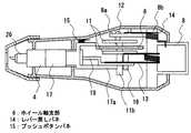
図1は本発明の実施の形態1による採血用穿刺器具の外観斜視図、図2は、同穿刺器具の内部構成を示す断面図、図3は上記穿刺器具に使用される穿刺針カートリッジの外観を示す斜視図である。この採血用穿刺器具、及び穿刺針カートリッジは、血糖値測定時のような少量の採血時に使用される。また、図4は、穿刺操作を行うために、穿刺針を器具本体にセットする操作を示した図である。Hereinafter, embodiments of the present invention will be described with reference to the drawings.
(Embodiment 1)
1 is an external perspective view of a blood sampling puncture device according to
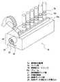
図1、及び図2に示すように、本発明の実施の形態1による穿刺器具1は、本体ボトムケース3を有し、この本体ボトムケース3内に、穿刺針保持ロッド4を設け、本体カバー2と、穿刺セットレバー8とが設けられている。穿刺針保持ロッド4内には、穿刺針5が所定の深さまで挿入されて装填される。この場合、穿刺針カートリッジ18上には、図3に示したように、複数の穿刺針5が一列に、樹脂一体成型でカートリッジのフレームに一体的に形成されて、配置されている。さらに、個々の穿刺針5は、穿刺針カートリッジ18のフレームとは、穿刺針分離溝5a部において、例えば、厚み0.1mm以下、の樹脂の薄膜でつながっており、穿刺針5の先端の針部は、カートリッジの本体フレーム側に埋没した状態でセットされている。 As shown in FIGS. 1 and 2, the
ここで、穿刺針5を、穿刺器具1に装着するための操作手順を示す。
まず、穿刺針セットレバー8をセットしていない状態(図示、下側に落ちている状態)で、穿刺器具1の穿刺針装填口9と、穿刺針カートリッジ18上の穿刺針5との軸を合致させながら、穿刺器具1を押し込む(図4(a))。このとき、操作を容易にするため、図3に示すように、並列的に配列された穿刺針5の一つ(図示左端のもの)を、予め有る角度だけ初期位置から起した状態にし、この状態で、穿刺器具1の穿刺針保持ロッド4内に案内された穿刺針5の後端部が、穿刺針保持ロッド4の穿刺針装填室10の底面を押す位置まで押し込む。この状態においては、穿刺針5のクビレ部(中央凹部)5bと、穿刺針保持ロッド4の入口部に設けられた穿刺針保持ツメ26とが係合する(図4(b))。このようにして、穿刺器具1の穿刺針保持ロッド4内に穿刺針5を保持した状態で、穿刺針カートリッジ18から穿刺器具1を後退、離間させると、穿刺器具1は前記穿刺針5を穿刺針カートリッジ18から引き離す動作を行うこととなる。この穿刺針を穿刺針カートリッジから引き離す動作の過程において、穿刺針5の先端部近傍の穿刺針分離溝5aに樹脂の薄膜に対して、これを引きちぎる力が発生する。この引きちぎる力(作用・反作用の力)に抗して操作者がさらに力を加えることで、穿刺針5を、穿刺針カートリッジ18の本体から引き離すこととなる(図4(c))。Here, an operation procedure for attaching the
First, in a state where the puncture
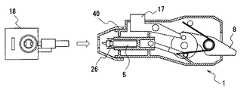
この後、この図4(c)の状態から、穿刺を行うために、穿刺針セットレバー8を所定の角度だけ図5(a)に示す矢印A方向に倒すようにすると、図5(a)の状態となり、穿刺動作の準備ができる。以下、この穿刺動作の準備のための動作、および穿刺動作について説明する。 Thereafter, in order to puncture from the state of FIG. 4 (c), the puncture
まず、穿刺器具1の先端部にある穿刺深さ調節リング40を軸中心に回転させて、該穿刺深さ調節リング40の、本穿刺器具1の軸方向上の位置をシフトさせることにより、予め決めた穿刺針5の穿刺する深さを設定する。 First, the puncture
その後、穿刺器具1の穿刺針保持ロッド4内に穿刺針5を装填した後、穿刺針セットレバー8を、図5(a)のように、矢印Aの方向へ所定の角度倒すようにすると、穿刺針セットレバー8上のホイール回動レバー部8aが、フライホイール11上のセットピン12と当接して、該フライホイール11をセット方向側に(図5(a)の矢印B方向に、すなわち、反時計回りに)回動させ、この際、フライホイール11とリンク19との結合点であるホイール係合ピン16が、該フライホイール11の回転に伴い、フライホイールセットバネ13の図示左辺部13bを、該フライホイールセットバネ13がより被圧縮状態となるよう押圧し、その最大の被圧縮状態を通過して、該フライホイールセットバネ13の左辺部13bがその右辺部13aとほぼ平行をなす状態となったあたりの、上記ホイール係合ピン16が、外部操作により回転可能に軸支された穿刺ボタン17の先端側のホイール係合ピン止めレバー部17aの先端辺部と当接することにより、前記フライホイール11の回転が係止して、図5(a)に示す穿刺動作の準備状態となる。 Then, after loading the
上記のように、図4(c)の状態から図5(a)の穿刺の準備状態になるまでにフライホイール11が所定角度回転する間に、該フライホイール11の回転運動を穿刺保持ロッド4の摺動運動に変換するリンク19により、該フライホイール11に連結された穿刺針保持ロッド4は、穿刺器具1の軸方向に摺動運動する。この間、フライホイール11上のホイール係合ピン16と、穿刺針保持ロッド4は、上記一本のリンク19によって連結されており、フライホイール11は、穿刺針セットレバー8により、前述のように決まった方向に(図示反時計方向に)だけ回転する構成となっているため、ホイール係合ピン16は、当初は、穿刺針保持ロッド4から遠ざかる方向へ回動が進行し、穿刺針保持ロッド4は、穿刺器具1の本体内へ沈み込む。その後、前述のように、フライホイール11がさらに回転し、そのホイール係合ピン16の先端部が、回動可能に軸支された穿刺ボタン17の先端部であるホイール係合ピン止めレバー部17aの先端辺部によって係止されて、フライホイール11が停止して、穿刺針保持ロッド4の動きも同時に停止し、フライホイール11は、フライホイールセットバネ13の付勢力により得られる回転する力を、穿刺準備位置にある穿刺ボタン17によって貯められた状態となって、セットが完了する(図5(a))。 As described above, while the
次に、穿刺動作について説明する。
上記図5(a)の状態において、穿刺ボタン17を押すと、該穿刺ボタン17が上方に回動するため、ホイール係合ピン止めレバー部17aが、ホイール係合ピン16を図示右方に押して、該ホイール係合ピン16は、フライホイール11を少し時計方向に回転させながら右方に移動して、上記ホイール係合ピン止めレバー部17aと、ホイール係合ピン16との係止が外れ、その結果、上記フライホイールセットバネ13の付勢力により得られる回転力を、貯めていた上記フライホイール11は、その力を一気に解放して、該フライホイール11は、その軸を中心として、一気に矢印B方向(反時計方向)に回動する。Next, a puncturing operation will be described.
In the state of FIG. 5A, when the
このとき、このフライホイール11とリンク19により連結されている穿刺針保持ロッド4は、穿刺器具1内から外側へ向かって直動(摺動移動)し、その後、フライホイール11の回転によって、リンク19が穿刺針保持ロッド4の長手方向の直線上の位置となる、穿刺針5が穿刺器具1から最大位置まで突き出した位置(図5(b))を通過した後は、穿刺針5は、フライホイール11の慣性力により、穿刺器具1内へ戻る動作を行う。この戻り動作時に、フライホイールセットバネ13の力により、リンク19の先端のホイール係合ピン16は、穿刺針セットレバー8の回転中心8bと、フライホイール11の回転中心11bとを結んだラインから最も遠い位置に至り、該位置にて停止するまで、該位置を中心として往復動作をしながら減衰して停止することとなるが、このとき、穿刺針保持ロッド4が、穿刺器具1から突き出す方向には戻らないようにする必要があるため、ホイール係合ピン16に対しては、該ホイール係合ピン16の動作を穿刺位置方向へ返さないように、ボトムケース3に植設された逆回転防止ツメ20を設けており、両者の係合によりフライホイール11の逆回転方向への動作を防止するようにしている(図5(c))。 At this time, the puncture
次に、上記穿刺動作を終えた穿刺針5を、廃棄する動作について説明する。
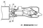
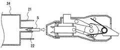
上述した穿刺動作を終えた状態で、穿刺器具1の穿刺針装填口9側を、穿刺針カートリッジ18の穿刺器具ガイド部21へ差し込む。このとき、穿刺器具ガイド部21内に配設された内側円筒部23の先端部にある穿刺針抜き取りツメ22が、穿刺針5のクビレ部5bに入り込む動作を行うと同時に、穿刺針抜き取りツメ22を持つ内側円筒部23の先端が、穿刺針保持ロッド4の先端部にある穿刺針保持ツメ26を、図6(a)のように外側へ押し広げる動作を行い、これにより、穿刺針5自体は、内側円筒部23へ取り込まれることになる(図6(b))。その後、穿刺器具1を引き抜くことによって、使用済みの穿刺針5を、上記穿刺針カートリッジ18内に把持させることができる。そののち、このように上記穿刺針カートリッジ18に把持された1回前の使用済み穿刺針5を、穿刺器具1で保持している次の使用済み穿刺針5で押し込むことにより、該1回前の使用済み穿刺針5を、穿刺針カートリッジ18の廃棄ボックス部24内に落下させるとともに、前記次の使用済み穿刺針5を、上記穿刺針カートリッジ18の内側円筒部23に把持させることができる。そして、これをつぎつぎと繰り返すことにより、使用済み穿刺針5を穿刺針カートリッジ18内に廃棄し、該カートリッジ18のすべての穿刺針を使用したのち、それを該カートリッジ18内、あるいはその内側円筒部23内に連続的に廃棄、あるいは把持させたのち、該カートリッジ18自体を廃棄することができる。Next, the operation of discarding the
In the state where the above-described puncturing operation is completed, the puncture
そして、この廃棄動作を連続的に、すなわちつぎつぎに行うことで、穿刺針5を連続的に穿刺針カートリッジ18内に廃棄することができる。The
さらに、穿刺針カートリッジ18の本体の、上記廃棄ボックス部24を構成する部分の側面には、図3に示したように、たとえば上記穿刺器具を用いて穿刺を行って得た血液に対して測定を行った使用済みの生体データ測定センサを廃棄するための挿入口25が形成されており、該挿入口25を介して上記使用済みの生体データ測定センサを投入することにより、使用済みの穿刺針と、該使用済みの該測定センサとを、使用後に一体的に廃棄することができるものである。Further, the main body of the
この発明は、特に、血糖値を測定する場合などに使用する、複数個の穿刺針から一個ずつ穿刺針を取り出す構成の採血用穿刺器具、およびそれ用の穿刺針カートリッジを提供するもので、血糖値等の測定に有用である。 In particular, the present invention provides a blood collection puncture device configured to take out puncture needles one by one from a plurality of puncture needles and a puncture needle cartridge for use in measuring blood glucose levels. This is useful for measuring values.
1 穿刺器具
2 本体上ケース
3 本体ボトムケース
4 穿刺針保持ロッド
5 穿刺針
5a 穿刺針分離溝
5b 穿刺針のクビレ部
6 ホイール軸支部
8 穿刺針セットレバー
8a ホイール回動部
8b セットレバー回転軸
9 穿刺針装填口
10 穿刺針装填室
11 フライホイール
12 セットピン
13 フライホイールセット用バネ
14 レバー戻しバネ
15 プッシュボタンバネ
16 ホイール係合ピン
17 穿刺ボタン
18 穿刺針カートリッジ
20 逆回転防止ツメ
21 穿刺器具ガイド部
22 穿刺針抜き取りツメ
23 内側円筒部
24 廃棄ボックス部
25 生体データ測定センサ挿入口
26 穿刺針保持ツメ
30 本体部分
31 突き出しロッド後端部
32 第1のバネ
33 下ケース
34 第2のバネ
36 穿刺部押圧面
40 穿刺深さ調節リング
47 穿刺針先端部
53 キャップDESCRIPTION OF
Claims (5)
Translated fromJapanese前記各穿刺針の後端側は、開放して終端されており、
前記複数の穿刺針は、各々が独立しており、かつ、
該各穿刺針は、前記複数の穿刺針が一平面内に並列配置されてなる状態から、該1つの穿刺針を該平面と交差する状態に倒す、または起こすことができるよう、その各先端側が可撓性を持って前記基台に連結されている、
ことを特徴とする穿刺針カートリッジ。Each needle a plurality of puncture needles formed by molding integrally with the resin, the tip end of the puncture needleis provided so as to continue integrally with theone of the base,
The rear end of each puncture needleis open-ended to,
Each of the plurality of puncture needles is independent; and
Each of the puncture needles has a distal end side so that the one puncture needle can be brought down or raised from a state where the plurality of puncture needles are arranged in parallel in one plane. Connected to the base with flexibility,
A puncture needle cartridge characterized by the above.
前記各穿刺針は、これを前記基台から切り離したとき該穿刺針の針部が露出し、前記穿刺針を覆っていたキャップ部分は、前記基台に一体的に連結された状態で残る、
ことを特徴とする穿刺針カートリッジ。The puncture needle cartridge accordingto claim1 ,
When each puncture needle is separated from the base, the needle portion of the puncture needle is exposed, and the cap portion covering the puncture needle remains in a state of being integrally connected to the base.
A puncture needle cartridge characterized by the above.
前記基台は、前記複数の穿刺針を一平面内に配置している側面と垂直の側面に、使用済み穿刺針把持機構を有する、
ことを特徴とする穿刺針カートリッジ。The puncture needle cartridge according to claim1 or 2 ,
The base is the side surfaces and vertical are arranged the plurality of puncture needles in aplane, with ause for pre puncture needle holding mechanism,
A puncture needle cartridge characterized by the above.
前記使用済み穿刺針把持機構は、該把持機構により把持された使用済み穿刺針を、外方より前記穿刺器具により保持された使用済み穿刺針により押圧すると、前記把持機構により把持されていた1回前の使用済み穿刺針が、該穿刺針カートリッジの廃棄ボックス部内に落下され、廃棄されるものである、
ことを特徴とする穿刺針カートリッジ。The puncture needle cartridge according to claim3 ,
Before Symbol used needle gripping mechanism, the used puncture needle is gripped by gripping mechanism, is pressed by the used puncture needle held by said lance from outside, has been gripped by the gripping mechanism 1 The used puncture needle before the rotation is dropped into the disposal box part of the puncture needle cartridge and discarded.
A puncture needle cartridge characterized by the above.
前記穿刺針は、その中央部に、穿刺器具内の穿刺針保持ロッドの穿刺針保持ツメで前記穿刺針の後方部を把持し、該穿刺針後方部をその前方部から離脱させるための係止凹部を有する、
ことを特徴とする穿刺針カートリッジ。The puncture needle cartridge according toany one of claims1 to 4 ,
The puncture needle is provided at its centralportion, and gripping the rear portion of the puncture needle in the puncture needle holding claws of the puncture needle holdingrod inpuncture barbs instrument engagement for detaching the puncture needle rear part from the front portion Having a stop,
A puncture needle cartridge characterized by the above.
Priority Applications (5)
| Application Number | Priority Date | Filing Date | Title |
|---|---|---|---|
| JP2003416967AJP4482318B2 (en) | 2003-12-15 | 2003-12-15 | Puncture needle cartridge |
| US11/010,475US7604118B2 (en) | 2003-12-15 | 2004-12-14 | Puncture needle cartridge and lancet for blood collection |
| US11/822,986US8147509B2 (en) | 2003-12-15 | 2007-07-11 | Puncture needle cartridge and lancet for blood collection |
| US13/405,631US8414608B2 (en) | 2003-12-15 | 2012-02-27 | Puncture needle cartridge and lancet for blood collection |
| US13/790,268US8556923B2 (en) | 2003-12-15 | 2013-03-08 | Puncture needle cartridge and lancet for blood collection |
Applications Claiming Priority (1)
| Application Number | Priority Date | Filing Date | Title |
|---|---|---|---|
| JP2003416967AJP4482318B2 (en) | 2003-12-15 | 2003-12-15 | Puncture needle cartridge |
Related Child Applications (1)
| Application Number | Title | Priority Date | Filing Date |
|---|---|---|---|
| JP2010019902ADivisionJP5012921B2 (en) | 2010-02-01 | 2010-02-01 | Blood sampling puncture device |
Publications (2)
| Publication Number | Publication Date |
|---|---|
| JP2005169003A JP2005169003A (en) | 2005-06-30 |
| JP4482318B2true JP4482318B2 (en) | 2010-06-16 |
Family
ID=34736020
Family Applications (1)
| Application Number | Title | Priority Date | Filing Date |
|---|---|---|---|
| JP2003416967AExpired - Fee RelatedJP4482318B2 (en) | 2003-12-15 | 2003-12-15 | Puncture needle cartridge |
Country Status (1)
| Country | Link |
|---|---|
| JP (1) | JP4482318B2 (en) |
Families Citing this family (4)
| Publication number | Priority date | Publication date | Assignee | Title |
|---|---|---|---|---|
| CA2671441C (en)* | 2006-12-01 | 2015-10-20 | Medipurpose Pte Ltd | A device for performing an incision |
| JP5948256B2 (en)* | 2011-02-14 | 2016-07-06 | 株式会社旭ポリスライダー | Lancet device |
| JP6429770B2 (en)* | 2012-06-18 | 2018-11-28 | ファセット テクノロジーズ エルエルシーFacet Technologies, LLC | One-way drive mechanism for puncture device |
| US11291389B2 (en)* | 2018-03-13 | 2022-04-05 | Phc Holdings Corporation | Sensor insertion device |
Family Cites Families (8)
| Publication number | Priority date | Publication date | Assignee | Title |
|---|---|---|---|---|
| US5514152A (en)* | 1994-08-16 | 1996-05-07 | Specialized Health Products, Inc. | Multiple segment encapsulated medical lancing device |
| JP3398598B2 (en)* | 1998-06-10 | 2003-04-21 | 松下電器産業株式会社 | Substrate quantification method and analytical element and measuring device used for the method |
| DE19840856B4 (en)* | 1998-09-07 | 2008-04-10 | Roche Diagnostics Gmbh | System for obtaining a body fluid, lancet magazine, lancet, lancet set, lancing device and method for removing a lancet from a lancet magazine and use of the system |
| JP3035292B1 (en)* | 1999-03-24 | 2000-04-24 | 日本イーライリリー株式会社 | Needle unit storage case |
| DE10010694A1 (en)* | 2000-03-04 | 2001-09-06 | Roche Diagnostics Gmbh | Lancet including tipped needle with body surrounding tip |
| DE10047419A1 (en)* | 2000-09-26 | 2002-04-11 | Roche Diagnostics Gmbh | Lancet system |
| CN101366633B (en)* | 2001-01-19 | 2011-03-30 | 松下电器产业株式会社 | Lancet-integrated sensor, measurement device, and biosensor case |
| US7343188B2 (en)* | 2002-05-09 | 2008-03-11 | Lifescan, Inc. | Devices and methods for accessing and analyzing physiological fluid |
- 2003
- 2003-12-15JPJP2003416967Apatent/JP4482318B2/ennot_activeExpired - Fee Related
Also Published As
| Publication number | Publication date |
|---|---|
| JP2005169003A (en) | 2005-06-30 |
Similar Documents
| Publication | Publication Date | Title |
|---|---|---|
| US7604118B2 (en) | Puncture needle cartridge and lancet for blood collection | |
| EP1790287B1 (en) | Centesis instrument | |
| WO2005011496A1 (en) | Puncturing instrument, puncturing needle cartridge, puncturing instrument set, and puncturing needle discardment instrument | |
| US5797942A (en) | Re-usable end cap for re-usable lancet devices for removing and disposing of a contaminated lancet | |
| US8361099B2 (en) | Puncture aid with protection against reuse | |
| US7655019B2 (en) | Blood sampling device | |
| JP3574800B2 (en) | Lancet system | |
| CN1275573C (en) | Punching assistance device including preventing repeately using lancet system | |
| CN1981702B (en) | Analyte monitoring system with integrated lancing apparatus | |
| US4503856A (en) | Lancet injector | |
| US20060247670A1 (en) | Lancing device with automatic lancet release | |
| JP5017730B2 (en) | Skin puncture device | |
| US20070249962A1 (en) | Method and apparatus for lancet launching device integrated onto a blood-sampling cartridge | |
| CN106573102B (en) | Insertion device with protection against reuse | |
| JP2003325484A (en) | Blood collection system | |
| EP0068864A2 (en) | Lancet injector | |
| KR101201034B1 (en) | Patient's skin puncturing device | |
| WO2006046570A1 (en) | Lancet and lancet device with the same | |
| JP4482318B2 (en) | Puncture needle cartridge | |
| CN102883657B (en) | Automatically triggered piercing aid | |
| JP5012921B2 (en) | Blood sampling puncture device | |
| CN117617958A (en) | Reusable applicator | |
| EP2601890A1 (en) | Lancet cartridge | |
| JP4538206B2 (en) | Puncture device set | |
| JP6255469B1 (en) | Auxiliary device for blood collection puncture device |
Legal Events
| Date | Code | Title | Description |
|---|---|---|---|
| A621 | Written request for application examination | Free format text:JAPANESE INTERMEDIATE CODE: A621 Effective date:20061213 | |
| A977 | Report on retrieval | Free format text:JAPANESE INTERMEDIATE CODE: A971007 Effective date:20091120 | |
| A131 | Notification of reasons for refusal | Free format text:JAPANESE INTERMEDIATE CODE: A131 Effective date:20091201 | |
| A521 | Request for written amendment filed | Free format text:JAPANESE INTERMEDIATE CODE: A523 Effective date:20100201 | |
| TRDD | Decision of grant or rejection written | ||
| A01 | Written decision to grant a patent or to grant a registration (utility model) | Free format text:JAPANESE INTERMEDIATE CODE: A01 Effective date:20100223 | |
| A01 | Written decision to grant a patent or to grant a registration (utility model) | Free format text:JAPANESE INTERMEDIATE CODE: A01 | |
| A61 | First payment of annual fees (during grant procedure) | Free format text:JAPANESE INTERMEDIATE CODE: A61 Effective date:20100319 | |
| FPAY | Renewal fee payment (event date is renewal date of database) | Free format text:PAYMENT UNTIL: 20130326 Year of fee payment:3 | |
| R150 | Certificate of patent or registration of utility model | Ref document number:4482318 Country of ref document:JP Free format text:JAPANESE INTERMEDIATE CODE: R150 Free format text:JAPANESE INTERMEDIATE CODE: R150 | |
| FPAY | Renewal fee payment (event date is renewal date of database) | Free format text:PAYMENT UNTIL: 20130326 Year of fee payment:3 | |
| FPAY | Renewal fee payment (event date is renewal date of database) | Free format text:PAYMENT UNTIL: 20140326 Year of fee payment:4 | |
| S111 | Request for change of ownership or part of ownership | Free format text:JAPANESE INTERMEDIATE CODE: R313113 | |
| R350 | Written notification of registration of transfer | Free format text:JAPANESE INTERMEDIATE CODE: R350 | |
| S111 | Request for change of ownership or part of ownership | Free format text:JAPANESE INTERMEDIATE CODE: R313113 | |
| R350 | Written notification of registration of transfer | Free format text:JAPANESE INTERMEDIATE CODE: R350 | |
| S111 | Request for change of ownership or part of ownership | Free format text:JAPANESE INTERMEDIATE CODE: R313113 | |
| R350 | Written notification of registration of transfer | Free format text:JAPANESE INTERMEDIATE CODE: R350 | |
| R250 | Receipt of annual fees | Free format text:JAPANESE INTERMEDIATE CODE: R250 | |
| R250 | Receipt of annual fees | Free format text:JAPANESE INTERMEDIATE CODE: R250 | |
| R250 | Receipt of annual fees | Free format text:JAPANESE INTERMEDIATE CODE: R250 | |
| R250 | Receipt of annual fees | Free format text:JAPANESE INTERMEDIATE CODE: R250 | |
| S533 | Written request for registration of change of name | Free format text:JAPANESE INTERMEDIATE CODE: R313533 | |
| R350 | Written notification of registration of transfer | Free format text:JAPANESE INTERMEDIATE CODE: R350 | |
| R250 | Receipt of annual fees | Free format text:JAPANESE INTERMEDIATE CODE: R250 | |
| R250 | Receipt of annual fees | Free format text:JAPANESE INTERMEDIATE CODE: R250 | |
| R250 | Receipt of annual fees | Free format text:JAPANESE INTERMEDIATE CODE: R250 | |
| LAPS | Cancellation because of no payment of annual fees |