JP4482218B2 - Luggage carrier - Google Patents
Luggage carrierDownload PDFInfo
- Publication number
- JP4482218B2 JP4482218B2JP2000336171AJP2000336171AJP4482218B2JP 4482218 B2JP4482218 B2JP 4482218B2JP 2000336171 AJP2000336171 AJP 2000336171AJP 2000336171 AJP2000336171 AJP 2000336171AJP 4482218 B2JP4482218 B2JP 4482218B2
- Authority
- JP
- Japan
- Prior art keywords
- frame
- load
- plate
- luggage
- caster
- Prior art date
- Legal status (The legal status is an assumption and is not a legal conclusion. Google has not performed a legal analysis and makes no representation as to the accuracy of the status listed.)
- Expired - Lifetime
Links
- 238000010276constructionMethods0.000description9
- 230000032258transportEffects0.000description9
- 239000000463materialSubstances0.000description5
- XEEYBQQBJWHFJM-UHFFFAOYSA-NIronChemical compound[Fe]XEEYBQQBJWHFJM-UHFFFAOYSA-N0.000description4
- 238000010586diagramMethods0.000description3
- 239000010720hydraulic oilSubstances0.000description2
- 229910052742ironInorganic materials0.000description2
- 230000002265preventionEffects0.000description2
- 229920001875EbonitePolymers0.000description1
- 230000037237body shapeEffects0.000description1
- 230000000694effectsEffects0.000description1
- 238000004519manufacturing processMethods0.000description1
- 238000000034methodMethods0.000description1
- 230000000630rising effectEffects0.000description1
Images


Landscapes
- Escalators And Moving Walkways (AREA)
- Loading Or Unloading Of Vehicles (AREA)
Description
Translated fromJapanese【0001】
【発明の属する技術分野】
本発明は、走行路を走行する車体を備える荷物運搬装置に係り、さらに詳しくは、例えば鉄道用の軌道を走行する車体を備え、駅のプラットホームとの間で荷物の搬入や搬出を行う荷物運搬装置に関する。
【0002】
【従来の技術】
例えば、地下鉄の既設の駅構内にエスカレータなどの構造物を追加工事により新設する場合には、まず、地上の基地局などにおいて、軌道上を走行する車体を備える荷物運搬装置に、工事に必要な資材や機材を積み込む。次いで、荷物運搬装置を、工事を行う駅まで走行させる。そして、荷物運搬装置からプラットホーム上に資材や機材を降ろし、これら資材などを工事現場に運び込んでいる。
【0003】
この種の従来の荷物運搬装置は、プラットホームの高さに略一致するように車体の上に角材を組み上げ、当該角材の上に資材や機材などの荷物を積み込んでいる。荷物運搬装置が工事を行う駅に到着すると、まず、箱ジャッキにより高さを微調整して、車体とプラットホームとの間に鉄板を掛け渡す。そして、荷物の下にコロ台車を入れ、荷物運搬装置からプラットホーム上に荷物を運び降ろしている。
【0004】
【発明が解決しようとする課題】
従来の荷物運搬装置にあっては、高さの微調整作業や鉄板を掛け渡す作業を人力で行っているため、作業手順が煩雑であり、さらに、安全性を確保するために多くの作業員を手配しなければならないという問題がある。
【0005】
鉄道に関連する工事では、線路を閉鎖している深夜の間に工事を完了しなければならないという時間的制約があるため、荷物を積み込んだり、荷降ろししたりするときの省力化を一層図ることが要請されている。
【0006】
本発明は、上記従来技術に伴う課題を解決するためになされたものであり、荷物を積み込んだり、荷降ろししたりするときの省力化を図り得る荷物運搬装置を提供することを目的とする。
【0007】
【課題を解決するための手段】
上記目的を達成するための本発明は、請求項ごとに次のように構成される。
【0008】
(1)鉄道用の軌道により構成される走行路を走行する車体と、
上下方向に移動可能に前記車体に支持されるフレームと、
荷物が載置されると共にローラを備える台車と、
前記台車が載置されると共に前記走行路の延伸方向に対して直交する幅方向にスライド移動可能に前記フレームに支持されるプレートと、
前記フレームを上下移動する第1駆動手段と、
前記プレートをスライド移動する第2駆動手段と、を有し、
前記荷物を前記台車ごと搬入出する駅のプラットホームであるステージ上に、スライド移動した前記プレートを掛け渡すようにしたことを特徴とする荷物運搬装置である。
【0009】
(2)前記フレームはさらに、前記ステージに向かう方向に傾斜可能に前記車体に支持され、
前記第1駆動手段はさらに、前記フレームを傾斜移動することを特徴とする上記(1)に記載の荷物運搬装置である。
【0010】
(3)前記第1駆動手段は、前記幅方向に沿って対をなすように配置された2つの伸張部材を含み、前記伸張部材のそれぞれの伸び量を異ならせることにより、前記フレームを傾斜移動することを特徴とする上記(2)に記載の荷物運搬装置である。
【0011】
(4)前記伸張部材の伸び量の差に基づいて、前記車体に対する前記フレームの傾斜角度を調節自在であることを特徴とする上記(3)に記載の荷物運搬装置である。
【0012】
(5)第2駆動手段は、前記幅方向の両側のそれぞれに、前記プレートをスライド移動自在であることを特徴とする上記(1)に記載の荷物運搬装置である。
【0014】
(6)前記台車は、前記荷物の一部に当接して当該荷物を保持する回動自在な可動ブラケットを備えていることを特徴とする上記(1)に記載の荷物運搬装置である。
【0016】
【発明の実施の形態】
以下、本発明の実施の形態を図面を参照しつつ説明する。
【0017】
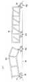
図1、図2および図3は、それぞれ、本発明の実施の形態に係る荷物運搬装置10を示す正面図、平面図および側面図である。図4は、荷物運搬装置10の要部を示す部分断面図、図5は、図4の5−5線に沿う断面図、図6は、図5に示される基準姿勢から、フレーム12が傾斜移動し、かつ、プレート13がスライド移動した姿勢を示す断面図である。図7および図8は、キャスタ台車61〜63上に載置された荷物としてのエスカレータ構造物50、51を、キャスタ台車61〜63ごと荷物運搬装置10に積み込んだ状態を示す正面図、図9(A)(B)は、第1のキャスタ台車61を示す正面図および側面図、図9(C)(D)は、第2のキャスタ台車62を示す正面図および側面図である。図10は、図7および図8に示されるそれぞれのエスカレータ構造物50、51を駅のプラットホーム16上で移動している状態を示す図、図11は、それぞれのエスカレータ構造物50、51を連結したアセンブリ52を駅のプラットホーム16上で移動している状態を示す図である。
【0018】
本実施形態の荷物運搬装置10は、概説すれば、走行路を走行するボギー台車11(車体に相当する)と、上下方向に移動可能にボギー台車11に支持されるフレーム12と、荷物が載置されると共に走行路の延伸方向に対して直交する幅方向にスライド移動可能にフレーム12に支持されるプレート13と、フレーム12を上下移動する第1駆動手段14と、プレート13をスライド移動する第2駆動手段15と、を有し、荷物を搬入出するステージ上に、スライド移動したプレート13を掛け渡すように構成されている。フレーム12はさらに、ステージに向かう方向に傾斜可能にボギー台車11に支持され、第1駆動手段14はさらに、フレーム12を傾斜移動するように構成されている。図示する実施形態においては、前記走行路は鉄道用の軌道17により構成され、前記ステージは駅のプラットホーム16である。荷物は、例えば、地下鉄の既設の駅構内での工事に必要な資材や機材であり、具体的には、エスカレータ構造物50、51である。
【0019】
荷物運搬装置10をさらに詳述する。
【0020】
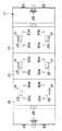
図1を参照して、ボギー台車11上に取り付けられたベース20に、3個のフレーム12がそれぞれ独立して上下方向に移動可能に支持されている。図2にも示すように、3個のフレーム12のそれぞれに、プレート13が独立して幅方向(図2においては上下方向に示される)にスライド移動可能に支持されている。各プレート13上には、積み込んだ荷物の転倒を防止する転倒防止柵21が着脱自在に取り付けられている。転倒防止柵21は、幅方向に沿って対向するように設けられている。
【0021】
図4に示すように、プレート13のスライド移動を案内するリニアベアリング23が、フレーム12の両側に、幅方向に伸びて取り付けられている。ベース20には、フレーム12の下面に当接して荷重を受ける支持ボルト26が設けられている。当該支持ボルト26は、ベース20上面からの突出寸法を調節自在となっている。
【0022】
第1駆動手段14は、油圧シリンダ30a〜30dから構成され、伸張部材としてのロッド31を含んでいる。油圧シリンダ30a〜30dは、ボギー台車11上に取り付けられた電動油圧ユニット22から所定油圧に調整された作動油が供給され、ロッド31を進退移動する。以下の説明では、第1駆動手段14を構成する油圧シリンダを、「傾斜用シリンダ」とも言う。
【0023】
本実施形態では、図2に破線で示すように、フレーム12ごとに4個の傾斜用シリンダ30a〜30dを設けてある。傾斜用シリンダ30aと30cとが幅方向に沿って対をなし、傾斜用シリンダ30bと30dとが幅方向に沿って対をなしている。傾斜用シリンダ30aと30b、および、傾斜用シリンダ30cと30dは、軌道17の延伸方向に沿って配置されている。
【0024】
図4〜図6に示すように、各傾斜用シリンダ30(30a〜30dの総称)の本体32は、軌道17の延伸方向と平行に配置される回動軸33を中心にして回動自在に、軸受部34を介してベース20に取り付けられている。各傾斜用シリンダ30のロッド31の先端は、軌道17の延伸方向と平行に配置される回動軸35を中心にして回動自在に、軸受部36を介してフレーム12に取り付けられている。
【0025】
ロッド31の伸び量が同じになるように各傾斜用シリンダ30を作動すると、フレーム12は、ベース20に対して平行な状態を維持したまま上下移動する。また、幅方向に沿って対をなす傾斜用シリンダ30aと30c(30bと30d)を、それぞれのロッド31の伸び量が異なるように、作動を制御することもできる。図6に示すように、ロッド31の伸び量を異ならせることにより、フレーム12が傾斜移動する。ボギー台車11に対するフレーム12の傾斜角度は、ロッド31の伸び量の差に基づいて調節自在である。なお、軌道17の延伸方向に沿って配置された傾斜用シリンダ30aと30b(30cと30d)同士は、ロッド31の伸び量が同じとなるように、作動が制御される。
【0026】
第2駆動手段15も、油圧シリンダ40から構成され、当該油圧シリンダ40は、電動油圧ユニット22から所定油圧に調整された作動油が供給され、ロッド41を進退移動する。以下の説明では、第2駆動手段15を構成する油圧シリンダを、「横行用シリンダ」とも言う。
【0027】
本実施形態では、図5および図6に示すように、横行用シリンダ40は、フレーム12ごとに1個ずつ設けてある。横行用シリンダ40の本体42は、幅方向に沿ってフレーム12内に取り付けられている。横行用シリンダ40のロッド41の先端は、プレート13の下面側に連結されている。
【0028】
図5に示される基準姿勢において、横行用シリンダ40のロッド41は、最大移動量(例えば、800mm)の1/2の寸法だけ伸びた位置にある。この基準姿勢からロッド41を後進限位置まで後進させることにより、図6に示されるように、プレート13は400mmだけ左行する。一方、基準姿勢からロッド41を前進限位置まで前進させることにより、プレート13は400mmだけ右行する。このように、横行用シリンダ40は、幅方向の両側のそれぞれにプレート13をスライド移動自在であり、所望の側から荷物の積み込みや荷降ろしを行うことができる。
【0029】
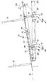
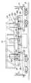
図7および図8に示すように、荷物としてのエスカレータ構造物50、51は、キャスタ台車61〜63上に載置され、キャスタ台車61〜63ごと荷物運搬装置10に積み込まれる。図7に示されるエスカレータ構造物50は屈曲体形状を呈する上部フレームであり、図8に示されるエスカレータ構造物51は直方体形状を呈する中間フレームである。積み込まれた上部フレーム50および中間フレーム51は、緊縛用のウィンチワイヤ24により、荷物運搬装置10に固定される。ウィンチワイヤ24は、電動ウィンチ25により巻き取られ、緊張状態に維持される。図1、図2、図4および図5に示すように、電動ウィンチ25は、両端に位置するフレーム12に1個ずつ、ベース20に6個の合計8個設けられている。
【0030】
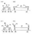
本実施形態のキャスタ台車61〜63には、図7の左手側に示される第1のキャスタ台車61、図7および図8の右手側に示される第2のキャスタ台車62、図8の左手側に示される第3のキャスタ台車63の3種類がある。図9(A)(B)には第1のキャスタ台車61が示され、図9(C)(D)には第2のキャスタ台車62が示される。なお、第3のキャスタ台車63は、載置台が平坦な一般的なキャスタ台車であるため詳細な図示および説明は省略する。
【0031】
図9(A)(B)に示すように、第1のキャスタ台車61は、4個のローラ65を備え、各ローラ65は、360度旋回自在な旋回部材66を介して載置台67の下面に取り付けられている。載置台67の上面には、受溝70が形成された受け座71が取り付けられている。受け座71は、硬質ゴムから形成されている。
【0032】
図9(C)(D)に示すように、第2のキャスタ台車62は、第1のキャスタ台車61と同様のローラ65および旋回部材66を備え、載置台67の上面には、上部フレーム50および中間フレーム51の一部に当接して各フレーム50、51を保持する可動ブラケット72が支軸73を中心に回動自在に設けられている。可動ブラケット72には、各フレーム50、51をピン連結するボルトが挿通される通孔74が形成されている。
【0033】
図7に示すように、上部フレーム50は、図中左端の下端エッジが受け座71に保持された状態で第1のキャスタ台車61上に載置され、図中右端の下端部が可動ブラケット72にピン連結された状態で第2のキャスタ台車62上に載置されている。
【0034】
図8に示すように、中間フレーム51は、図中左端寄りの下部が第3のキャスタ台車63上に載置され、図中右端の下端部が可動ブラケット72にピン連結された状態で第2のキャスタ台車62上に載置されている。
【0035】
次に、本実施形態の作用を説明する。
【0036】
上部フレーム50および中間フレーム51を積み込んだ荷物運搬装置10が工事を行う駅のプラットホーム16に到着すると、まず、上部フレーム50および中間フレーム51を緊縛しているウィンチワイヤ24を若干緩める。
【0037】
次いで、幅方向に沿って対をなすように配置された傾斜用シリンダ30aと30c(30bと30d)を、プラットホーム16の高さに合致するように高さの微調整を行いつつ、ロッド31の伸び量が異なるように作動させる。これにより、フレーム12は、図6に示すように、基準姿勢(図5)から傾斜移動する。ボギー台車11に対するフレーム12の傾斜角度は、ロッド31のそれぞれの伸び量の差に基づいて調節される。
【0038】
フレーム12の傾斜移動が終了すると、横行用シリンダ40のロッド41を後進限位置まで後進させる。これにより、プレート13は、図6に示すように、基準姿勢(図5)から所定寸法(例えば、400mm)だけ左行する。荷物運搬装置10と駅のプラットホーム16との間には隙間があるが、スライド移動したプレート13が荷物運搬装置10からプラットホーム16に掛け渡される。
【0039】
そして、ウィンチワイヤ24を徐々に緩めていくと、上部フレーム50および中間フレーム51は、キャスタ台車61〜63ごと、その自重によって、傾斜移動したプレート13に沿ってプラットホーム16に向けて移動する。
【0040】
図10には、プラットホーム16上にキャスタ台車61〜63ごと降ろされた上部フレーム50および中間フレーム51が示される。上部フレーム50および中間フレーム51は、図中矢印で示す方向に、図示しないワイヤなどで牽引され、プラットホーム16上を移動する。牽引に伴って、進行方向前側の部分がキャスタ台車61、63から持ち上がることがある。この前側部分の持ち上がりに応じて、進行方向後側の部分にピン連結された可動ブラケット72の角度が変化する。これにより、第2のキャスタ台車62が上部フレーム50および中間フレーム51から外れる事態を防止することができる。
【0041】
図11には、上部フレーム50の図中右端と中間フレーム51の図中左端とを連結したアセンブリ52が示される。このようなアセンブリ52を形成する場合、上部フレーム50の図中左端の下端エッジが受け座71の受溝70に係合しているため、第1のキャスタ台車61が上部フレーム50から外れることはなく、中間フレーム51の図中右端の下端部が可動ブラケット72にピン連結されているため、第2のキャスタ台車62が中間フレーム51から外れることはない。上部フレーム50と中間フレーム51とのアセンブリ52を図中矢印で示す方向に牽引する場合に、牽引に伴って、進行方向前側の部分がキャスタ台車61から持ち上がったとしても、上述したのと同様にして、第2のキャスタ台車62が中間フレーム51から外れる事態を防止することができる。
【0042】
プラットホーム16から荷物運搬装置10に荷物を積み込む場合には、荷物運搬装置10とプラットホーム16との間に掛け渡されたプレート13に沿って、キャスタ台車61〜63に載置された荷物をキャスタ台車61〜63ごと運び込めばよい。荷物が重量物である場合には、電動ウィンチ25を利用して荷物をキャスタ台車61〜63ごと牽引すれば、プレート13が昇り傾斜していても当該荷物を荷物運搬装置10に容易に積み込むことができる。
【0043】
上述のとおり本実施形態の荷物運搬装置10によれば、傾斜用シリンダ30により高さの微調整作業を行うことができ、横行用シリンダ40によりプラットホーム16との間にプレート13を掛け渡すことができ、荷物を積み込んだり、荷降ろししたりするときの省力化を達成でき、時間的制約がある工事などに使用して好適なものとなる。さらに、人力による作業が減るのに伴って作業員数を減らすことができ、工費の低減にも寄与し得る。
【0044】
なお、エスカレータ構造物50、51を地下鉄の駅に運搬する実施形態について説明したが、本発明はこの場合に限定されるものではなく、走行路を走行して荷物を運搬する荷物運搬装置に広く適用できる。例えば、製造、組み立て、保管などを行う各ステージ間で荷物を運搬する荷物運搬装置にも適用することができる。
【0045】
【発明の効果】
以上説明したように、請求項1〜請求項4に記載の発明によれば、第1駆動手段により高さの微調整作業を行うことができ、第2駆動手段によりステージとの間にプレートを掛け渡すことができ、荷物を積み込んだり、荷降ろししたりするときの省力化を達成できる。さらに、荷物は、ローラを備える台車上に載置され、当該台車ごとプレート上に載置されるので、荷物の積み込みや荷降ろしをより一層簡単に行うことができる。荷物を積み込んだり、荷降ろししたりするときの省力化を図ることができるので、時間的制約がある鉄道に関連する工事に使用して好適なものとなり、人力による作業が減るのに伴って作業員数を減らすことができ、工費の低減にも寄与し得る。
【0046】
請求項5に記載の発明によれば、幅方向の両側のうち所望の側から荷物の積み込みや荷降ろしを行うことができる。
【0048】
請求項6に記載の発明によれば、荷物の動きに合わせて可動ブラケットの角度が変化することにより、台車が荷物から外れる事態を防止することができる。
【図面の簡単な説明】
【図1】 本発明の実施の形態に係る荷物運搬装置を示す正面図である。
【図2】 同荷物運搬装置を示す平面図である。
【図3】 同荷物運搬装置を示す側面図である。
【図4】 荷物運搬装置の要部を示す部分断面図である。
【図5】 図4の5−5線に沿う断面図である。
【図6】 図5に示される基準姿勢から、フレームが傾斜移動し、かつ、プレートがスライド移動した姿勢を示す断面図である。
【図7】 キャスタ台車上に載置された荷物としてのエスカレータ構造物を、キャスタ台車ごと荷物運搬装置に積み込んだ状態を示す正面図である。
【図8】 キャスタ台車上に載置された荷物としての他のエスカレータ構造物を、キャスタ台車ごと荷物運搬装置に積み込んだ状態を示す正面図である。
【図9】 図9(A)(B)は、第1のキャスタ台車を示す正面図および側面図、図9(C)(D)は、第2のキャスタ台車を示す正面図および側面図である。
【図10】 図7および図8に示されるそれぞれのエスカレータ構造物を駅のプラットホーム上で移動している状態を示す図である。
【図11】 それぞれのエスカレータ構造物を連結したアセンブリを駅のプラットホーム上で移動している状態を示す図である。
【符号の説明】
10…荷物運搬装置
11…ボギー台車(車体)
12…フレーム
13…プレート
14…第1駆動手段
15…第2駆動手段
16…駅のプラットホーム(ステージ)
17…鉄道用の軌道(走行路)
30(30a〜30d)…傾斜用シリンダ(第1駆動手段)
31…ロッド(伸張部材)
40…横行用シリンダ(第2駆動手段)
41…ロッド
50、51…エスカレータ構造物(荷物)
61〜63…キャスター台車(台車)
65…ローラ
72…可動ブラケット[0001]
BACKGROUND OF THE INVENTION
The present invention relates to a baggage transport device including a vehicle body that travels on a travel path, and more particularly, to a cargo transport device that includes a vehicle body that travels on a railroad track, for example, and that loads and unloads luggage with a platform of a station. Relates to the device.
[0002]
[Prior art]
For example, when constructing a new structure such as an escalator in an existing subway station by an additional work, first, in a base station on the ground, etc., it is necessary to construct a luggage carrier equipped with a vehicle body that runs on the track. Load materials and equipment. Next, the baggage carrier is driven to the station where the construction is performed. Then, materials and equipment are unloaded from the luggage transport device onto the platform, and these materials are carried to the construction site.
[0003]
In this type of conventional baggage transport device, square bars are assembled on the vehicle body so as to substantially match the height of the platform, and loads such as materials and equipment are loaded on the square bars. When the luggage transporter arrives at the station where the work is to be performed, the height is finely adjusted by a box jack, and an iron plate is placed between the vehicle body and the platform. Then, a roller cart is placed under the luggage, and the luggage is carried on the platform from the luggage transportation device.
[0004]
[Problems to be solved by the invention]
In the conventional baggage handling device, the work procedure is complicated because the fine adjustment of the height and the work of transferring the iron plate are performed manually, and many workers are required to ensure safety. Have the problem of having to arrange.
[0005]
In the construction work related to the railway, for which there is a time constraint that must be completed the construction work between midnight and closing the line, Dari embarked luggage, more possible to reduce the labor-saving of whenor unloading Is requested.
[0006]
The present invention has been made in order to solve the problems associated with the prior art described above, and an object of the present invention is to provide a load carrying device capable of saving labor when loading and unloading loads.
[0007]
[Means for Solving the Problems]
To achieve the above object, the present invention is configured as follows for each claim.
[0008]
(1) a vehicle body that travels on a travel pathconstituted by railroad tracks ;
A frame supported by the vehicle body so as to be movable in the vertical direction;
A carriage on which a load is placed and a roller is provided;
A plate on which thecarriage is mounted and supported by the frame so as to be slidable in a width direction perpendicular to the extending direction of the travel path;
First driving means for moving the frame up and down;
Second driving means for slidingly moving the plate,
The load on the stageis a platform of the station for loading and unloadingeach said carriage, a load-carrying device which is characterized in that so as to bridge the plate slides.
[0009]
(2) The frame is further supported by the vehicle body to be tiltable in a direction toward the stage,
Said 1st drive means is a load transport apparatus as described in said (1) characterized by further carrying out the inclination movement of the said flame | frame.
[0010]
(3) The first driving means includes two extension members arranged to form a pair along the width direction, and the frame is tilted and moved by varying the extension amounts of the extension members. The load carrying apparatus according to (2) above, characterized in that:
[0011]
(4) The load carrying apparatus according to (3), wherein an inclination angle of the frame with respect to the vehicle body is adjustable based on a difference in extension amount of the extension member.
[0012]
(5) The luggage transport device according to (1), wherein the second driving means is capable of sliding the plate on both sides in the width direction.
[0014]
(6 ) The load carrying apparatus according to (1 ), wherein the carriage includes a rotatable movable bracket that contacts a part of the load and holds the load.
[0016]
DETAILED DESCRIPTION OF THE INVENTION
Hereinafter, embodiments of the present invention will be described with reference to the drawings.
[0017]
1, 2, and 3 are a front view, a plan view, and a side view, respectively, showing a
[0018]
Briefly, the
[0019]
The
[0020]
Referring to FIG. 1, three
[0021]
As shown in FIG. 4,
[0022]
The 1st drive means 14 is comprised from the
[0023]
In the present embodiment, as shown by broken lines in FIG. 2, four tilting
[0024]
As shown in FIGS. 4 to 6, the
[0025]
When each tilting cylinder 30 is operated so that the amount of extension of the
[0026]
The second driving means 15 is also composed of a
[0027]
In the present embodiment, as shown in FIGS. 5 and 6, one
[0028]
In the reference posture shown in FIG. 5, the
[0029]
As shown in FIGS. 7 and 8, the
[0030]
The
[0031]
As shown in FIGS. 9A and 9B, the
[0032]
As shown in FIGS. 9C and 9D, the
[0033]
As shown in FIG. 7, the
[0034]
As shown in FIG. 8, the
[0035]
Next, the operation of this embodiment will be described.
[0036]
When the
[0037]
Next, the tilting
[0038]
When the tilt movement of the
[0039]
When the
[0040]
FIG. 10 shows the
[0041]
FIG. 11 shows an
[0042]
When loading a load from the
[0043]
As described above, according to the
[0044]
In addition, although embodiment which conveys the
[0045]
【The invention's effect】
As described above, according to the first to fourth aspects of the invention, the fine adjustment operation of the height can be performed by the first driving means, and the plate is placed between the stage by the second driving means. It can be handed over, and labor saving when loading and unloading can be achieved.Furthermore, since the load is placed on a carriage provided with rollers and placed on the plate together with the carriage, the loading and unloading of the luggage can be performed more easily. It is possible to save labor when loading and unloading luggage, so it is suitable for work related to railways with time constraints, and work as human work is reduced The number can be reduced and it can contribute to the reduction of construction cost.
[0046]
According to the fifth aspect of the present invention, it is possible to load and unload a load from a desired side of both sides in the width direction.
[0048]
According to thesixth aspect of the present invention, the angle of the movable bracket changes in accordance with the movement of the load, thereby preventing the carriage from coming off the load.
[Brief description of the drawings]
FIG. 1 is a front view showing a luggage carrier according to an embodiment of the present invention.
FIG. 2 is a plan view showing the load carrying device.
FIG. 3 is a side view showing the load carrying device.
FIG. 4 is a partial cross-sectional view showing a main part of the load carrying device.
5 is a cross-sectional view taken along line 5-5 of FIG.
6 is a cross-sectional view showing a posture in which a frame is tilted and a plate is slid from the reference posture shown in FIG. 5;
FIG. 7 is a front view showing a state in which an escalator structure as a load placed on a caster cart is loaded together with the caster cart on a load transporting device.
FIG. 8 is a front view showing a state in which another escalator structure as a load placed on a caster cart is loaded on the load carrying device together with the caster cart.
9A and 9B are a front view and a side view showing the first caster carriage, and FIGS. 9C and 9D are a front view and a side view showing the second caster carriage. is there.
FIG. 10 is a diagram showing a state in which each escalator structure shown in FIGS. 7 and 8 is moving on the platform of the station.
FIG. 11 is a view showing a state in which an assembly connecting each escalator structure is moving on a platform of a station.
[Explanation of symbols]
10 ... Luggage carrier 11 ... Bogie cart (body)
12 ...
17 ... Railroad tracks (travel paths)
30 (30a-30d) ... Cylinder for tilting (first driving means)
31 ... Rod (extension member)
40 ... Traverse cylinder (second drive means)
41 ...
61-63 ... Caster cart (cart)
65 ...
Claims (6)
Translated fromJapanese上下方向に移動可能に前記車体(11)に支持されるフレーム(12)と、
荷物(50、51)が載置されると共にローラ(65)を備える台車(61〜63)と、
前記台車(61〜63)が載置されると共に前記走行路(17)の延伸方向に対して直交する幅方向にスライド移動可能に前記フレーム(12)に支持されるプレート(13)と、
前記フレーム(12)を上下移動する第1駆動手段(14)と、
前記プレート(13)をスライド移動する第2駆動手段(15)と、を有し、
前記荷物(50、51)を前記台車(61〜63)ごと搬入出する駅のプラットホームであるステージ(16)上に、スライド移動した前記プレート(13)を掛け渡すようにしたことを特徴とする荷物運搬装置。A vehicle body (11) that travels on a travel path (17)constituted by a railroad track ;
A frame (12) supported by the vehicle body (11) so as to be movable in the vertical direction;
A carriage (61-63) on which a load (50, 51) is placed and provided with a roller (65);
A plate (13) on which thecarriage (61-63) is mounted and supported by the frame (12) so as to be slidable in a width direction perpendicular to the extending direction of the travel path (17);
First driving means (14) for moving the frame (12) up and down;
Second driving means (15) for slidingly moving the plate (13),
The slidably moved plate (13) is placed ona stage (16)which is a platform of astationfor carrying the cargo (50, 51) together with thecart (61-63). Luggage carrier.
前記第1駆動手段(14)はさらに、前記フレーム(12)を傾斜移動することを特徴とする請求項1に記載の荷物運搬装置。The frame (12) is further supported by the vehicle body (11) so as to be tiltable in a direction toward the stage (16),
The load carrying device according to claim 1, wherein the first driving means (14) further tilts the frame (12).
Priority Applications (1)
| Application Number | Priority Date | Filing Date | Title |
|---|---|---|---|
| JP2000336171AJP4482218B2 (en) | 2000-11-02 | 2000-11-02 | Luggage carrier |
Applications Claiming Priority (1)
| Application Number | Priority Date | Filing Date | Title |
|---|---|---|---|
| JP2000336171AJP4482218B2 (en) | 2000-11-02 | 2000-11-02 | Luggage carrier |
Publications (2)
| Publication Number | Publication Date |
|---|---|
| JP2002137728A JP2002137728A (en) | 2002-05-14 |
| JP4482218B2true JP4482218B2 (en) | 2010-06-16 |
Family
ID=18811789
Family Applications (1)
| Application Number | Title | Priority Date | Filing Date |
|---|---|---|---|
| JP2000336171AExpired - LifetimeJP4482218B2 (en) | 2000-11-02 | 2000-11-02 | Luggage carrier |
Country Status (1)
| Country | Link |
|---|---|
| JP (1) | JP4482218B2 (en) |
Families Citing this family (3)
| Publication number | Priority date | Publication date | Assignee | Title |
|---|---|---|---|---|
| JP2012061880A (en)* | 2010-09-14 | 2012-03-29 | Nippon Signal Co Ltd:The | Platform fence carrying device |
| KR102045679B1 (en)* | 2018-06-28 | 2019-11-15 | 주식회사 포스코 | Apparatus for correcting shape of coil |
| CN109017836B (en)* | 2018-09-12 | 2020-09-29 | 东阳市天齐科技有限公司 | Mine transport vehicle |
- 2000
- 2000-11-02JPJP2000336171Apatent/JP4482218B2/ennot_activeExpired - Lifetime
Also Published As
| Publication number | Publication date |
|---|---|
| JP2002137728A (en) | 2002-05-14 |
Similar Documents
| Publication | Publication Date | Title |
|---|---|---|
| RU2547024C2 (en) | Forklift truck linkage | |
| WO2011118246A1 (en) | Workpiece conveyance device | |
| CN108910755B (en) | A multifunctional transport truck | |
| JP2009051290A (en) | Conveyor using trolley | |
| JPH01502897A (en) | Transport vehicle | |
| JP6217927B2 (en) | Carriage transfer device | |
| HUT76963A (en) | Process and device for transferring freight | |
| JPS60204598A (en) | Method of placing floor-surface conveyor and constitution offloor-surface conveyor | |
| JP2018100587A (en) | Rail transport vehicle | |
| CN1097535C (en) | Terminal for transferring containers, and container car | |
| JP4482218B2 (en) | Luggage carrier | |
| US3262580A (en) | Slewable gantry crane | |
| US20170021841A1 (en) | Jump Rail System | |
| US20100104407A1 (en) | Container utility system | |
| JP2000025618A (en) | Long heavy goods carriage | |
| KR101824898B1 (en) | Weight transport and Mounting and demounting apparatus of truck crane | |
| JPH08133467A (en) | Pallet transfer equipment for carrying in/out cargo | |
| JPH07228357A (en) | Truck loader | |
| JP4734803B2 (en) | Cargo transportation vehicle | |
| JP2934591B2 (en) | Transfer device | |
| JP7630686B1 (en) | Conveyor | |
| CN115467202B (en) | A functional component installation system for high-speed maglev track beam | |
| JP7660430B2 (en) | System and method for transporting long members | |
| JP3231716U (en) | Rail carrier | |
| CN115352511B (en) | Bearing platform truck |
Legal Events
| Date | Code | Title | Description |
|---|---|---|---|
| A711 | Notification of change in applicant | Free format text:JAPANESE INTERMEDIATE CODE: A712 Effective date:20040422 | |
| A521 | Written amendment | Free format text:JAPANESE INTERMEDIATE CODE: A821 Effective date:20040929 | |
| RD02 | Notification of acceptance of power of attorney | Free format text:JAPANESE INTERMEDIATE CODE: A7422 Effective date:20040929 | |
| A521 | Written amendment | Free format text:JAPANESE INTERMEDIATE CODE: A821 Effective date:20040929 | |
| A621 | Written request for application examination | Free format text:JAPANESE INTERMEDIATE CODE: A621 Effective date:20070615 | |
| A977 | Report on retrieval | Free format text:JAPANESE INTERMEDIATE CODE: A971007 Effective date:20091112 | |
| A131 | Notification of reasons for refusal | Free format text:JAPANESE INTERMEDIATE CODE: A131 Effective date:20091124 | |
| A521 | Written amendment | Free format text:JAPANESE INTERMEDIATE CODE: A523 Effective date:20100122 | |
| TRDD | Decision of grant or rejection written | ||
| A01 | Written decision to grant a patent or to grant a registration (utility model) | Free format text:JAPANESE INTERMEDIATE CODE: A01 Effective date:20100309 | |
| A01 | Written decision to grant a patent or to grant a registration (utility model) | Free format text:JAPANESE INTERMEDIATE CODE: A01 | |
| A61 | First payment of annual fees (during grant procedure) | Free format text:JAPANESE INTERMEDIATE CODE: A61 Effective date:20100319 | |
| FPAY | Renewal fee payment (event date is renewal date of database) | Free format text:PAYMENT UNTIL: 20130326 Year of fee payment:3 | |
| R150 | Certificate of patent or registration of utility model | Ref document number:4482218 Country of ref document:JP Free format text:JAPANESE INTERMEDIATE CODE: R150 Free format text:JAPANESE INTERMEDIATE CODE: R150 | |
| FPAY | Renewal fee payment (event date is renewal date of database) | Free format text:PAYMENT UNTIL: 20130326 Year of fee payment:3 | |
| FPAY | Renewal fee payment (event date is renewal date of database) | Free format text:PAYMENT UNTIL: 20140326 Year of fee payment:4 | |
| R250 | Receipt of annual fees | Free format text:JAPANESE INTERMEDIATE CODE: R250 | |
| R250 | Receipt of annual fees | Free format text:JAPANESE INTERMEDIATE CODE: R250 | |
| R250 | Receipt of annual fees | Free format text:JAPANESE INTERMEDIATE CODE: R250 | |
| R250 | Receipt of annual fees | Free format text:JAPANESE INTERMEDIATE CODE: R250 | |
| R250 | Receipt of annual fees | Free format text:JAPANESE INTERMEDIATE CODE: R250 | |
| R250 | Receipt of annual fees | Free format text:JAPANESE INTERMEDIATE CODE: R250 | |
| R250 | Receipt of annual fees | Free format text:JAPANESE INTERMEDIATE CODE: R250 | |
| R250 | Receipt of annual fees | Free format text:JAPANESE INTERMEDIATE CODE: R250 | |
| EXPY | Cancellation because of completion of term |