JP4481029B2 - Endoscopic treatment tool - Google Patents
Endoscopic treatment toolDownload PDFInfo
- Publication number
- JP4481029B2 JP4481029B2JP2004030651AJP2004030651AJP4481029B2JP 4481029 B2JP4481029 B2JP 4481029B2JP 2004030651 AJP2004030651 AJP 2004030651AJP 2004030651 AJP2004030651 AJP 2004030651AJP 4481029 B2JP4481029 B2JP 4481029B2
- Authority
- JP
- Japan
- Prior art keywords
- hook
- endoscope
- insertion portion
- engaged
- treatment
- Prior art date
- Legal status (The legal status is an assumption and is not a legal conclusion. Google has not performed a legal analysis and makes no representation as to the accuracy of the status listed.)
- Expired - Lifetime
Links
- 238000012277endoscopic treatmentMethods0.000titleclaimsdescription12
- 238000003780insertionMethods0.000claimsdescription168
- 230000037431insertionEffects0.000claimsdescription168
- 238000011282treatmentMethods0.000claimsdescription129
- 238000001574biopsyMethods0.000claimsdescription36
- 210000001519tissueAnatomy0.000description25
- 210000003811fingerAnatomy0.000description12
- 238000005452bendingMethods0.000description4
- 238000003384imaging methodMethods0.000description4
- 238000005286illuminationMethods0.000description3
- 238000000034methodMethods0.000description2
- 230000001681protective effectEffects0.000description2
- 238000005299abrasionMethods0.000description1
- 210000000078clawAnatomy0.000description1
- 230000000694effectsEffects0.000description1
- 238000001727in vivoMethods0.000description1
- 230000001678irradiating effectEffects0.000description1
- 238000012423maintenanceMethods0.000description1
- 239000002184metalSubstances0.000description1
- 210000004400mucous membraneAnatomy0.000description1
- 230000035515penetrationEffects0.000description1
- 210000003813thumbAnatomy0.000description1
Images


Classifications
- A—HUMAN NECESSITIES
- A61—MEDICAL OR VETERINARY SCIENCE; HYGIENE
- A61B—DIAGNOSIS; SURGERY; IDENTIFICATION
- A61B10/00—Instruments for taking body samples for diagnostic purposes; Other methods or instruments for diagnosis, e.g. for vaccination diagnosis, sex determination or ovulation-period determination; Throat striking implements
- A61B10/02—Instruments for taking cell samples or for biopsy
- A61B10/06—Biopsy forceps, e.g. with cup-shaped jaws
- A—HUMAN NECESSITIES
- A61—MEDICAL OR VETERINARY SCIENCE; HYGIENE
- A61B—DIAGNOSIS; SURGERY; IDENTIFICATION
- A61B1/00—Instruments for performing medical examinations of the interior of cavities or tubes of the body by visual or photographical inspection, e.g. endoscopes; Illuminating arrangements therefor
- A61B1/00002—Operational features of endoscopes
- A61B1/00039—Operational features of endoscopes provided with input arrangements for the user
- A61B1/00042—Operational features of endoscopes provided with input arrangements for the user for mechanical operation
- A—HUMAN NECESSITIES
- A61—MEDICAL OR VETERINARY SCIENCE; HYGIENE
- A61B—DIAGNOSIS; SURGERY; IDENTIFICATION
- A61B1/00—Instruments for performing medical examinations of the interior of cavities or tubes of the body by visual or photographical inspection, e.g. endoscopes; Illuminating arrangements therefor
- A61B1/012—Instruments for performing medical examinations of the interior of cavities or tubes of the body by visual or photographical inspection, e.g. endoscopes; Illuminating arrangements therefor characterised by internal passages or accessories therefor
- A61B1/018—Instruments for performing medical examinations of the interior of cavities or tubes of the body by visual or photographical inspection, e.g. endoscopes; Illuminating arrangements therefor characterised by internal passages or accessories therefor for receiving instruments
- A—HUMAN NECESSITIES
- A61—MEDICAL OR VETERINARY SCIENCE; HYGIENE
- A61B—DIAGNOSIS; SURGERY; IDENTIFICATION
- A61B10/00—Instruments for taking body samples for diagnostic purposes; Other methods or instruments for diagnosis, e.g. for vaccination diagnosis, sex determination or ovulation-period determination; Throat striking implements
- A61B10/02—Instruments for taking cell samples or for biopsy
- A61B10/04—Endoscopic instruments, e.g. catheter-type instruments
- A—HUMAN NECESSITIES
- A61—MEDICAL OR VETERINARY SCIENCE; HYGIENE
- A61B—DIAGNOSIS; SURGERY; IDENTIFICATION
- A61B10/00—Instruments for taking body samples for diagnostic purposes; Other methods or instruments for diagnosis, e.g. for vaccination diagnosis, sex determination or ovulation-period determination; Throat striking implements
- A61B10/02—Instruments for taking cell samples or for biopsy
- A61B2010/0216—Sampling brushes
- A—HUMAN NECESSITIES
- A61—MEDICAL OR VETERINARY SCIENCE; HYGIENE
- A61B—DIAGNOSIS; SURGERY; IDENTIFICATION
- A61B17/00—Surgical instruments, devices or methods
- A61B17/00234—Surgical instruments, devices or methods for minimally invasive surgery
- A61B2017/00292—Surgical instruments, devices or methods for minimally invasive surgery mounted on or guided by flexible, e.g. catheter-like, means
- A61B2017/00296—Surgical instruments, devices or methods for minimally invasive surgery mounted on or guided by flexible, e.g. catheter-like, means mounted on an endoscope
- A—HUMAN NECESSITIES
- A61—MEDICAL OR VETERINARY SCIENCE; HYGIENE
- A61B—DIAGNOSIS; SURGERY; IDENTIFICATION
- A61B17/00—Surgical instruments, devices or methods
- A61B17/28—Surgical forceps
- A61B17/29—Forceps for use in minimally invasive surgery
- A61B17/2909—Handles
- A61B2017/291—Handles the position of the handle being adjustable with respect to the shaft
- A—HUMAN NECESSITIES
- A61—MEDICAL OR VETERINARY SCIENCE; HYGIENE
- A61B—DIAGNOSIS; SURGERY; IDENTIFICATION
- A61B17/00—Surgical instruments, devices or methods
- A61B17/34—Trocars; Puncturing needles
- A61B2017/347—Locking means, e.g. for locking instrument in cannula
- A—HUMAN NECESSITIES
- A61—MEDICAL OR VETERINARY SCIENCE; HYGIENE
- A61B—DIAGNOSIS; SURGERY; IDENTIFICATION
- A61B90/00—Instruments, implements or accessories specially adapted for surgery or diagnosis and not covered by any of the groups A61B1/00 - A61B50/00, e.g. for luxation treatment or for protecting wound edges
- A61B90/50—Supports for surgical instruments, e.g. articulated arms
Landscapes
- Health & Medical Sciences (AREA)
- Life Sciences & Earth Sciences (AREA)
- Surgery (AREA)
- Engineering & Computer Science (AREA)
- Molecular Biology (AREA)
- Public Health (AREA)
- Nuclear Medicine, Radiotherapy & Molecular Imaging (AREA)
- Biomedical Technology (AREA)
- Heart & Thoracic Surgery (AREA)
- Medical Informatics (AREA)
- Veterinary Medicine (AREA)
- Animal Behavior & Ethology (AREA)
- General Health & Medical Sciences (AREA)
- Pathology (AREA)
- Physics & Mathematics (AREA)
- Biophysics (AREA)
- Optics & Photonics (AREA)
- Radiology & Medical Imaging (AREA)
- Biodiversity & Conservation Biology (AREA)
- Mechanical Engineering (AREA)
- Surgical Instruments (AREA)
- Endoscopes (AREA)
Description
Translated fromJapanese本発明は、内視鏡のチャンネルに挿通させて用いる内視鏡用処置具に関する。 The present invention relates to an endoscope treatment tool that is used by being inserted into a channel of an endoscope.
人体の検査や治療を行うために、体腔内の生体組織などを採取することがある。このような場合には、内視鏡のチャンネルに生検鉗子や、細胞診ブラシといった処置具を挿入し、所望の生体組織を採取等する手法が採られている。
ここで、生検鉗子を用いる場合には、体外側の操作部を操作して、鉗子部を構成する生検カップを開閉させて生体組織を挟み込む。この状態で、生検鉗子を体外側に後退させて、生検カップ内の生体組織を引き離し、回収する(例えば、特許文献1参照)。
また、細胞診ブラシの場合は、体外側の操作部を操作して、可撓性のシースの先端からブラシ部を突出させる。さらに、ブラシ部をシースごと進退移動させると、細胞診ブラシ部で粘膜が擦過されるので、擦過により得られた細胞がブラシ部と共に回収される(例えば、特許文献2参照)。
Here, when using a biopsy forceps, an operation part outside the body is operated to open and close a biopsy cup that constitutes the forceps part to sandwich the living tissue. In this state, the biopsy forceps are retracted to the outside of the body, and the biological tissue in the biopsy cup is pulled away and collected (see, for example, Patent Document 1).
In the case of a cytodiagnosis brush, the operation part outside the body is operated to cause the brush part to protrude from the distal end of the flexible sheath. Further, when the brush part is moved forward and backward together with the sheath, the mucous membrane is abraded by the cytodiagnosis brush part, so that the cells obtained by abrasion are collected together with the brush part (see, for example, Patent Document 2).
ところで、このような処置具の操作を内視鏡操作者が一人で行うことは困難であった。例えば、生検鉗子の場合には、介助者が、内視鏡操作者の指示に従って生検カップを開閉させ、内視鏡操作者が処置具を進退させて、生体組織を切除する。また、細胞診ブラシの場合には、介助者が操作部を操作してブラシ部をシースから突出させ、内視鏡操作者がシースを掴んで細胞診ブラシを進退させていた。つまり、内視鏡操作者は、処置を行うにあたり、介助者の協力を受けなければならなかった。このため、内視鏡操作者が一人で簡単に操作できるような処置具の開発が望まれていた。
また、内視鏡操作者が操作部を保持したままで、挿入部を引っ張った場合には、処置部を後退させることはできるが、挿入部に大きな負荷がかかるので好ましくない。
この発明は、このような事情に着目してなされたものであり、その目的とするところは、内視鏡操作者が処置具を一人で操作できるような内視鏡用処置具を提供することである。By the way, it is difficult for an endoscope operator to perform such operation of the treatment tool alone. For example, in the case of a biopsy forceps, an assistant opens and closes a biopsy cup according to an instruction from the endoscope operator, and the endoscope operator advances and retracts the treatment tool to cut away the living tissue. In the case of the cytodiagnosis brush, the assistant operates the operation part to project the brush part from the sheath, and the endoscope operator grasps the sheath and advances and retracts the cytodiagnosis brush. In other words, the endoscope operator had to receive the assistance of an assistant in performing the treatment. Therefore, it has been desired to develop a treatment instrument that can be easily operated by an endoscope operator alone.
Further, when the endoscope operator pulls the insertion portion while holding the operation portion, the treatment portion can be retracted, but it is not preferable because a large load is applied to the insertion portion.
The present invention has been made paying attention to such circumstances, and an object of the present invention is to provide an endoscopic treatment tool that allows an endoscopic operator to operate the treatment tool alone. It is.
上記の課題を解決する本発明の請求項1に係る発明は、内視鏡のチャンネル内に挿入可能な挿入部と、前記挿入部の基端部に設けられ、前記内視鏡のチャンネル内に配置した前記挿入部を前記挿入部の基端部と共に前記チャンネルに対して進退させる操作部と、前記挿入部の基端よりも前記操作部の基端部側に配置されているとともに前記操作部に形成された係合部と、前記挿入部において前記内視鏡の鉗子口から露出する部分とを係合させることによって、前記挿入部に対して前記挿入部の長軸方向に前記操作部を位置決めする係合手段と、を有することを特徴とする内視鏡用処置具とした。
この内視鏡用処置具では、挿入部の内視鏡から露出する部分と、操作部とを係合手段で係合させるので、操作部を移動させると、これに連動して挿入部が内視鏡に対して進退する。つまり、操作部を保持している手を動かすだけで、挿入部を進退させることができる。なお、係合手段は、操作部又は挿入部の一方の設けても良いし、操作部及び挿入部のそれぞれに設けても良い。The invention according to
In this endoscope treatment tool, the portion exposed from the endoscope of the insertion portion and the operation portion are engaged by the engaging means. Therefore, when the operation portion is moved, the insertion portion is interlocked with the inner portion. Move forward and backward with respect to the endoscope. That is, the insertion part can be advanced and retracted simply by moving the hand holding the operation part. Note that the engaging means may be provided in one of the operation unit and the insertion unit, or may be provided in each of the operation unit and the insertion unit.
請求項2に係る発明は、請求項1に記載の内視鏡用処置具において、前記操作部は、指をかけて保持する保持部分を有し、前記係合手段は、前記操作部において前記保持部分よりも先端側に設けられていることを特徴とする。
この内視鏡用処置具では、係合手段により挿入部と係合する位置が、操作部を保持する位置よりも前側になるので、操作部と挿入部とを係合させた状態で、挿入部を進退させやすい。このため、内視鏡と処置具との操作を一人で簡単に行える。According to a second aspect of the present invention, in the endoscope treatment instrument according to the first aspect, the operation portion includes a holding portion that is held by holding a finger, and the engaging means is provided in the operation portion. It is provided in the front end side rather than the holding | maintenance part, It is characterized by the above-mentioned.
In this endoscope treatment tool, the position where the engaging portion is engaged with the insertion portion is in front of the position where the operation portion is held, so the insertion is performed with the operation portion and the insertion portion engaged. It is easy to move the club forward and backward. Therefore, the operation of the endoscope and the treatment tool can be easily performed by one person.
請求項3に係る発明は、請求項1に記載の内視鏡用処置具において、前記係合手段は、前記挿入部又は前記操作部に設けられたフックと、前記フックが係合する被係合部材とからなることを特徴とする。
この内視鏡用処置具では、係合手段として、フックと被係合部材とを有する。例えば、フックを操作部に設け、被係合部材を挿入部に設けた場合には、操作部を被係合部材に近接させて、フックと被係合部材とを係合させる。フックは係脱が容易であるために、操作部と挿入部と係脱も容易になる。なお、フックを挿入部に設け、被係合部材を操作部に設けても同様の作用が得られる。According to a third aspect of the present invention, in the endoscope treatment instrument according to the first aspect, the engaging means includes a hook provided in the insertion portion or the operation portion, and a hook engaged with the hook. It consists of a joint member.
This endoscope treatment tool has a hook and an engaged member as engaging means. For example, when the hook is provided in the operation portion and the engaged member is provided in the insertion portion, the operation portion is brought close to the engaged member, and the hook and the engaged member are engaged. Since the hook can be easily engaged and disengaged, the operation portion and the insertion portion can be easily disengaged. The same effect can be obtained by providing the hook in the insertion portion and the engaged member in the operation portion.
請求項4に係る発明は、請求項1に記載の内視鏡用処置具において、前記係合手段は、前記挿入部又は前記操作部に設けられ、切り欠きが形成された第一係合部材と、前記切り欠きの幅よりも径が大きい大径部を備える第二係合部材とからなることを特徴とする。
この内視鏡用処置具では、係合手段として、第一係合部材と第二係合部材とを有する。例えば、第一係合部材を操作部に設けた場合には、切り欠きを有する第一係合部材で挿入部を挟みながら操作部を一定の方向に移動させる。そして、第一係合部材と第二係合部材とを当接させると、操作部を一定の方向に移動させる間は、操作部と挿入部とが係合する。また、第二係合部材に、切り欠きに係合可能な凹部を設けても良い。According to a fourth aspect of the present invention, in the endoscope treatment instrument according to the first aspect, the engagement means is provided in the insertion portion or the operation portion, and a first engagement member formed with a notch. And a second engagement member having a large diameter portion having a diameter larger than the width of the notch.
This endoscope treatment instrument has a first engagement member and a second engagement member as engagement means. For example, when the first engagement member is provided in the operation portion, the operation portion is moved in a certain direction while the insertion portion is sandwiched between the first engagement members having notches. When the first engagement member and the second engagement member are brought into contact with each other, the operation unit and the insertion unit are engaged while the operation unit is moved in a certain direction. Moreover, you may provide the recessed part which can be engaged with a notch in a 2nd engagement member.
請求項5に係る発明は、請求項1に記載の内視鏡用処置具において、前記係合手段は、前記挿入部又は前記操作部を把持する挟持部材であることを特徴とする。
この内視鏡用処置具では、挟持部材により挿入部と操作部とを係合させる。例えば、挟持部材を操作部に設けた場合には、挟持部材で挿入部を挟持させると、操作部を保持している手を動かすだけで、挿入部を進退させることができる。According to a fifth aspect of the present invention, in the endoscope treatment instrument according to the first aspect, the engaging means is a holding member that holds the insertion portion or the operation portion.
In this endoscope treatment tool, the insertion portion and the operation portion are engaged by the holding member. For example, when the holding member is provided in the operation part, if the insertion part is held by the holding member, the insertion part can be advanced and retracted only by moving the hand holding the operation part.
請求項6に係る発明は、請求項1から請求項5のいずれか一項に記載の内視鏡用処置具において、前記係合手段は、前記挿入部と前記操作部とが交差するように係合させることを特徴とする。
この内視鏡用処置具では、係合手段が、挿入部と操作部とが交差するように係合させる。これにより、操作部の移動させる手の動きが、より自然なものになる。さらに、操作部が内視鏡などと干渉し難くなる。According to a sixth aspect of the present invention, in the endoscope treatment tool according to any one of the first to fifth aspects, the engaging means is configured so that the insertion portion and the operation portion intersect. It is made to engage.
In this endoscope treatment tool, the engaging means engages the insertion portion and the operation portion so as to intersect each other. Thereby, the movement of the hand moved by the operation unit becomes more natural. Furthermore, it becomes difficult for the operation unit to interfere with an endoscope or the like.
請求項7に係る発明は、請求項1から請求項6のいずれか一項に記載の内視鏡用処置具において、前記処置具は、生検鉗子又は細胞診ブラシであることを特徴とする。
この内視鏡用処置具では、生検鉗子や、細胞診ブラシのように、処置部を操作しつつ、挿入部を進退させる必要がある処置具において、一人で内視鏡と処置具の操作が行えるようになる。
請求項8に係る発明は、請求項1に記載の内視鏡用処置具において、前記操作部は、前記挿入部に対して前記係合手段を介して着脱自在であることを特徴とする。
請求項9に係る発明は、請求項1に記載の内視鏡用処置具において、前記挿入部の先端に配置された処置部と、前記操作部と前記処置部とのそれぞれに連結され、前記挿入部に沿って配置され、前記処置部を動作可能な操作ワイヤと、をさらに有し、前記操作部は、前記挿入部と前記ワイヤとを相対的に動作可能であることを特徴とする。The invention according to
In this endoscopic treatment tool, the operation of the endoscope and the treatment tool alone, such as a biopsy forceps and a cytodiagnosis brush, in which the treatment part needs to be advanced and retracted while operating the treatment part Can be done.
According to an eighth aspect of the present invention, in the endoscope treatment tool according to the first aspect, the operation portion is detachable from the insertion portion via the engagement means.
The invention according to
この発明によれば、係合手段を備えることにより、内視鏡に挿入した挿入部と、操作部とを内視鏡の外側で係合させることができるので、操作部を動かすだけで、挿入部を進退させることができる。したがって、内視鏡の操作と、内視鏡用の処置具の操作とを簡単に、一人で行うことができるようになる。 According to this invention, by providing the engagement means, the insertion portion inserted into the endoscope and the operation portion can be engaged on the outside of the endoscope. Therefore, the insertion portion can be inserted simply by moving the operation portion. The part can be advanced and retracted. Therefore, the operation of the endoscope and the operation of the endoscope treatment tool can be easily performed by one person.
発明を実施するための最良の形態について図面を参照しながら詳細に説明する。
図1に示すように、第一の実施の形態における内視鏡システムは、内視鏡1と、内視鏡1の鉗子チャンネル2に挿入される内視鏡用処置具(以下、処置具とする)3と、内視鏡1にユニバーサルコード4で接続されたコントロールユニット(不図示)とを備えている。なお、コントロールユニットには、内視鏡1で撮像した画像の処理及び表示をする装置や、撮像のための照明用光源などが含まれている。The best mode for carrying out the invention will be described in detail with reference to the drawings.
As shown in FIG. 1, an endoscope system according to a first embodiment includes an
内視鏡1は、生体内に挿入される可撓性の挿入部6と、挿入部6の基端(体外)側に接続された操作部7とを備えている。
挿入部6の先端には、角度変向が可能な湾曲部8が設けられている。さらに、湾曲部8の先端には、先端カバー9が接続されており、ここに、体内を観察する撮像部と、照明光を照射する照射部などが内蔵されている。また、先端カバー9の先端面には、処置具挿通チャンネル2の開口が形成されている。ここで、処置具挿通チャンネル2は、操作部7側に鉗子口2aを有しており、体外と体内とを連通させている。なお、鉗子口2aには、鉗子口2aを覆うように鉗子栓10が取り付けられている。The
A bending portion 8 capable of changing the angle is provided at the distal end of the
操作部7は、前記鉗子口2aの他に、複数のスイッチ11と、複数の操作ノブ12とを備えている。スイッチ11としては、撮像部で撮影した画像の記録を行うスイッチや、照明の切り替えを行うスイッチなどがある。各スイッチ11の信号は、ユニバーサルコード4を介してコントロールユニットに送られるようになっている。また、操作ノブ12としては、湾曲部8を所定の方向に変向させるノブや、変向させた湾曲部8の角度を保持させるノブなどがある。 The
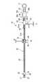
図2に示すように、処置具3は、生検鉗子である。この処置具3は、処置具挿通チャンネル2(図1参照)内に挿入される可撓性のシース20で覆われた挿入部21と、挿入部21の先端側に設けられた処置部22と、処置部22などを操作するために挿入部21の基端側に設けられた操作部(ハンドル)23と、処置部22から挿入部21内を通り、操作部23に引き出される操作ワイヤ24とを有している。 As shown in FIG. 2, the
挿入部21のシース20は、金属製又はプラスチック製のコイルシースから形成されている。さらに、挿入部21の基端側には、後述する被係合部材25が取り付けられている。
処置部22は、挿入部21の先端に固定された支持部材(先端カバー)26を有している。この支持部材26の先端には、対向して配置される一対の生検カップ27が支軸28によって回動自在に支持されている。各生検カップ27は、椀形状を有し、支持部材26内に設けられたリンク機構(不図示)の一端に連結されている。リンク機構の他端は、操作ワイヤ24に連結されている。つまり、操作ワイヤ24を進退させると、支軸28を中心として生検カップ27が回動するようになっている。
操作ワイヤ24は、処置部22のリンク機構の他端に連結された一端から、支持部材26内及び挿入部21内を進退自在に挿通し、その他端が操作部23において、内視鏡操作者が指をかけるスライダ29に連結されている。The
The
The
操作部23は、先端に挿入部21の基端が固定された操作部本体30を有している。この操作部本体30には、スライダ29が摺動自在に取り付けられている。
操作部本体30は、細長形状を有し、先端側に比べて、基端側が拡径している。操作部本体30の基端には、指掛けリング31が取り付けられている。また、操作部本体30の基端から先端に至るまでの間で、拡径された部分には、操作部本体30の長さ方向に沿ってスリット32が設けられている。このスリット32は、操作部本体30を径方向に貫通している。さらに、図2及び図3に示すように、スリット32から操作部本体30の先端面に至るまでの間には、操作ワイヤ24を進退自在に挿通させる挿通孔33が形成されている。
図2に示すように、スライダ(保持部分)29は、スリット32に沿ってスライド自在に操作部本体30に嵌め込まれた円筒部材からなる。スライダ29の先端及び基端には、スライダ29よりも外径の大きいつば部34a及びつば部34bが設けられている。そして、前記のように、スライダ29には、操作ワイヤ24の他端が固定されている。
なお、操作部本体30の先端には、挿入部21の外周を覆う保護部材35が取り付けられている。この保護部材35は、操作部23を操作する際に、操作部23との固定箇所の近傍で挿入部21が折り曲げられることを防止する。The
The operation unit
As shown in FIG. 2, the slider (holding portion) 29 is formed of a cylindrical member that is fitted in the operation unit
A
ここで、挿入部21と、操作部23のそれぞれには、両者を係合させる係合手段が取り付けられている。
挿入部21側の係合手段(第二係合部材)は、挿入部21において、内視鏡1(図1参照)から露出する部分に取り付けられた被係合部材25である。被係合部材25は、挿入部21の外径d2よりも大きい外径d1が有する大径部である。
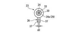
操作部23側の係合手段(第一係合部材)は、スライダ29の先端側に設けられたつば部34aに取り付けられたフック36である。フック36は、スライダ29から径方向外側に向かって延設されている。図3に示すように、フック36は、先端部が切り欠かれており、2つの係合片37が配列された、略U字形状になっている。切り欠きの大きさ、つまり係合片37の配置間隔d3は、挿入部21の外径d2よりも大きく、被係合部材25の外径d1よりは小さい。Here, each of the
The engaging means (second engaging member) on the
The engaging means (first engaging member) on the
次に、処置具3の動作について説明する。
まず、図1に示す内視鏡1の挿入部6を患者の体内に挿入する。次に、内視鏡1の処置具挿通チャンネル2に処置具3を先端側から挿入する。このとき、内視鏡1の撮像部で撮影した体内画像などを参照しつつ、採取しようとする生体組織の近傍に至るまで、処置部3を内視鏡1の挿入部6の先端から突出させる。
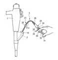
処置具3を挿入したら、施術者は、親指を指掛けリング31に掛け、人指し指と中指でスライダ29を挟み、図4に示すように操作部23を保持する。そして、スライダ29を進退させて生検カップ27を開閉し、所望の生体組織を一対の生検カップ27で挟み込む。Next, the operation of the
First, the
When the
具体的には、スライダ29を操作部23の先端側に前進させ、操作ワイヤ24を挿入部21側に押し込ませる。これにより、図2に示すような処置部22は、内部のリンク機構の一端が操作ワイヤ24によって先端側に押し進められるので、リンク機構が稼動し、一対の生検カップ27が支軸28を中心にして開く。
この状態で、図5に示すように、被係合部材25よりも操作部23側から、フック36を挿入部21に引っ掛け、フック36と被係合部材25の基端側の面25aと係合させる。さらに、フック36を鉗子口2aに近接させるように操作部23を移動させ、挿入部21を押し進め、生検カップ27を生体組織に押し付ける。
その後、スライダ29を後退させると、操作ワイヤ24がリンク機構の他端を引っ張る。これにより、生検カップ27が生体組織を挟むようにして閉じる。Specifically, the
In this state, as shown in FIG. 5, the
Thereafter, when the
一対の生検カップ27で生体組織を挟み込んだら、図6に示すように、フック36と被係合部材25との係合位置を変える。すなわち、フック36を被係合部材25の先端側の面25bと係合させる。そして、フック36と被係合部材25とを係合させた状態で、フック36を処置具挿通チャンネル2の鉗子口2aから遠ざけるように、操作部23を引き上げる。これにより、操作部23の移動量に応じて、被係合部材25と共に挿入部21が、処置具挿通チャンネル2から引き出される。つまり、処置具3が内視鏡1から引き抜かれるように移動するので、図2に示すような処置部22は内視鏡1に向かって後退するように移動し、生検カップ27に挟まれている生体組織が引きちぎられる。
生体組織を引きちぎった後は、処置具3を処置具挿通チャンネル2から抜去し、生体組織を回収する。When the living tissue is sandwiched between the pair of biopsy cups 27, the engagement position between the
After tearing off the living tissue, the
この実施の形態によれば、図5及び図6に示すように、挿入部21において処置具挿通チャンネル2の鉗子口2aから操作部23に至るまでの部分21aに被係合部材25を取り付け、操作部23に被係合部材25と係合するフック36を設けたので、挿入部21を直接掴まなくても、係合の向きを変えることで、処置部22を生体組織などに向かって押し込んだり、処置部22を体外側に向けて引き戻したりすることが可能になる。したがって、施術者は、介助者を必要とせずに生検カップ27の開閉及び進退が行えるようになる。また、フック36が、スライダ29の先端側のつば部34aに取り付けられているので、操作部23を保持する位置よりも先端側で挿入部21と係合させることができるので、自然な動きで生検カップ27の開閉及び進退が行えるようになる。
また、挿入部21を引っ張る力は、フック36が引っ掛かった場所、つまり被係合部材25に集中するので、挿入部21を効率良く引き戻すことができ、所望の生体組織を採取し易い。According to this embodiment, as shown in FIGS. 5 and 6, the engaged
Moreover, since the force pulling the
さらに、操作部23と挿入部21とを同時に手で掴む必要がなくなるので、操作部23を反転させた場合でも、挿入部21が過度に曲げられることはなく、挿入部21の湾曲させた部分21b(図5参照)への応力集中を防止できる。なお、被係合部材25の取り付け位置は、内視鏡1から露出する部分21aであって、処置具挿通チャンネル2の鉗子口2aに近い位置であることが望ましい。このようにすることで、フック36と被係合部材25とを係合させたときに、挿入部21の湾曲させた部分21bにかかる負荷をさらに小さくすることができる。 Furthermore, since there is no need to grasp the
次に、本発明の第二の実施の形態について詳細に説明する。なお、第一の実施の形態と同じ構成要素には同一の符号を付してある。また、第一の実施の形態と重複する説明は省略する。
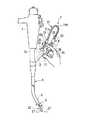
図7に示すように、処置具40は、可撓性の挿入部21を有し、挿入部21の先端に、一対の生検カップ27を備える処置部22が設けられている。さらに、挿入部21の基端には、操作部23が設けられている。Next, a second embodiment of the present invention will be described in detail. In addition, the same code | symbol is attached | subjected to the same component as 1st embodiment. Moreover, the description which overlaps with 1st embodiment is abbreviate | omitted.
As shown in FIG. 7, the
この実施の形態における係合手段は、挿入部21の内視鏡1から露出する部分21aに設けられた被係合部材41と、操作部23に取り付けられた係合部材であるフック42とからなる。
被係合部材41は、挿入部21を覆う円筒形状の本体43と、本体43に固定された引っ掛け部44とを有している。引っ掛け部44は、本体43に対して約180°位相がずれた位置に1つずつ、合計2つ取り付けられている。さらに、各引っ掛け部44には、挿入部21の長さ方向と略直交する向きに貫通孔45が形成されている。
フック42は、一端部がスライダ29の先端側のつば部34aに固定されており、ここから操作部本体30の基端側(指掛けリング31側)に向かって延設されている。このフック42には、操作部23の長さ方向に沿って、二つの切り欠き42a,42bが形成されており、略H字状になっている。なお、切り欠き42aは、操作部23の先端側に向かって開放端を有し、切り欠き42bは、操作部23の基端(指かけリング31)側に向かって開放端を有している。各切り欠き42a,42bの幅は、引っ掛け部44の壁部の厚さ及び幅よりも大きい。The engaging means in this embodiment includes an engaged
The engaged
One end portion of the
この処置具40を操作する際には、処置具挿入チャンネル2に挿通させた状態で、操作部23を操作して一対の生検カップ27を開かせた後に、挿入部21と操作部23とを先端側に向かって係合させる。すなわち、フック42の切り欠き42bの開放端を挿入部21の先端側に向け、フック42を貫通孔45内から先端側に向かって引っ掛け部44と係合させる。
この状態で、フック42が鉗子口2aに近接するように操作部35を移動させ、挿入部3を推し進め、生検カップ27を生体組織に押し付ける。
スライダ29を引き戻すと、一対の生検カップ27が閉じ、生体組織が挟み込まれるので、挿入部21の基端側に向かってフック42と被係合部材41とを係合させる。すなわち、フック42の切り欠き42aの開放端を挿入部21の基端側に向け、フック42を貫通孔45内から基端側に向かって引掛け部44と係合させる。
この状態で、フック42を内視鏡1の挿入口(図1参照)から引き離す方向に操作部23を移動させると、フック42を介して挿入部21が引っ張られ、操作部23の移動量に応じて挿入部21が内視鏡1から引き戻される。これにより、体内の処置部22が後退し、一対の生検カップ27に挟まれた生体組織が引きちぎられる。When operating the
In this state, the operating
When the
In this state, when the
この実施の形態では、挿入部21において処置具挿通チャンネル2の鉗子口2aから操作部23に至るまでの部分21aに引っ掛け部44を設け、操作部23のつば部34aにフック42を設けたので、挿入部21を直接掴まなくても、係合向きを変えることで処置部22を生体組織などに向かって推し進めたり、処置部22を体外側へ引き戻したりすることが可能になる。したがって、施術者は、自然な動きで生検カップ27の開閉及び後退が行えるようになる。 In this embodiment, the
なお、引っ掛け部44の貫通孔45は、その長さ方向が挿入部21の長さ方向と平行になるように形成されても良い。また、引っ掛け部44の形状は、貫通孔45を備える環状の部材に限定されない。例えば、本体43から、その径方向外側に向かって突出させたピンでも良い。この場合のピンは、フック42の一端部と他端部との間の距離よりも小さい外径を有する。 The through
次に、本発明の第三の実施の形態について詳細に説明する。なお、前記各実施の形態と同じ構成要素には同一の符号を付してある。また、前記各実施の形態と重複する説明は省略する。
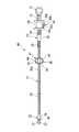
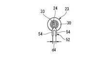
図8に示すように、処置具50は、可撓性の挿入部21において内視鏡1(図1参照)から露出する部分21aに被係合部材51が設けられ、操作部23の操作部本体30にフック52が設けられている。そして、被係合部材51とフック52とで係合手段が形成されている。Next, a third embodiment of the present invention will be described in detail. In addition, the same code | symbol is attached | subjected to the same component as each said embodiment. Further, the description overlapping with each of the embodiments is omitted.
As shown in FIG. 8, the
被係合部材51は、挿入部21のシース20に外装された円筒形状の部材からなる。この被係合部材51には、その先端から基端に至るまでの間に、外周に沿って外径を縮小させたリング状の溝が設けられており、この溝が引っ掛け部53になっている。
フック52は、操作部本体30の先端からスリット32に至るまでの間の所定位置に取り付けられている。このフック52は、操作部本体30側の基端部から操作部本体30の径方向外側に向かって延びている。図9に示すように、フック52の先端部は、切り欠かれて、略U字形状になっている。切り欠きの幅、つまり2つの係合片54の間の距離d4は、図8に示す被係合部材51の大径部の外径d5よりも小さく、小径部である引っ掛け部53の外径d6よりも大きい。また、図8に示すように、係合片54の厚さt1は、引っ掛け部53の幅w1よりも小さい。なお、係合片54の厚さt1とは、操作部本体30の長さ方向に平行な方向における長さをいう。The engaged
The
この処置具50の操作について、図8及び図10を参照して説明する。
最初に、処置具挿入チャンネル2に挿通させた状態で、操作部23を操作して一対の生検カップ27を開かせた後に、挿入部21と操作部23とを先端側に向かって係合させる。すなわち、フック52を被係合部材51の大径部の間に形成されている引っ掛け部53に係合させる。
この状態で、フック52が処置具挿通チャンネル2に向かうように、操作部23を移動させると、フック52に係合している被係合部材51が処置具挿通チャンネル2に向かって前進する。このときに、被係合部材51が固定されている挿入部21も処置具挿通チャンネル2に向かって前進し、その分だけ処置部22が内視鏡1の先端で前進する。
生検カップ27が所望の生体組織に押し付けられるまで処置部22を前進させたら、スライダ29を後退させ、一対の生検カップ27を閉じて、生体組織を挟み込む。
そして、フック52を処置具挿通チャンネル2から引き離すように、操作部23を移動させると、フック52と係合する被係合部材51が移動する。これに伴い、被係合部材51が固定されている挿入部21が引き戻され、体内の処置部22が後退し、生検カップ27内の生体組織が引きちぎられる。The operation of the
First, in a state where the treatment
In this state, when the
When the
And if the
この実施の形態によれば、前記各実施の形態と同様に、フック52と引っ掛け部53とを係合させることで、処置部22を体外側へ引き戻すことが可能になる。
さらに、引っ掛け部53を被係合部材51に設けた溝としたので、処置部22を後退させる方向のみならず、処置部22を前進させる方向にも、フック52と被係合部材51とを付け変えることなく処置部22を移動させることができる。According to this embodiment, the
Furthermore, since the
次に、本発明の第四の実施の形態について詳細に説明する。なお、前記各実施の形態と同じ構成要素には同一の符号を付してある。また、前記各実施の形態と重複する説明は省略する。
図11に示すように、この処置具60は、細胞診ブラシである。処置具60の挿入部61は、可撓性を有し、その内部に操作ワイヤ62が挿通されている。操作ワイヤ62の一端には、処置部であるブラシ部63が取り付けられている。ブラシ部63は、非使用時には、挿入部61内に収容できるようになっている。挿入部61の基端には、操作部64のハンドル部66が接続されている。また、挿入部61の基端近傍は、ハンドル部66に接続された保護部材65で覆われている。さらに、操作ワイヤ62の他端は、操作部64のハンドル部66を貫通し、指掛けハンドル67に接続されている。ハンドル部66の先端及び基端のそれぞれには、外径が大きいつば部68a及びつば部68bが設けられている。Next, a fourth embodiment of the present invention will be described in detail. In addition, the same code | symbol is attached | subjected to the same component as each said embodiment. Further, the description overlapping with each of the embodiments is omitted.
As shown in FIG. 11, the
この処置具60における係合手段は、挿入部61の内視鏡1(図13参照)から露出する部分61aに取り付けられた被係合部材51と、操作部64に取り付けられたフック69とから構成されている。
フック69は、基端部がハンドル67の先端側のつば部68aに取り付けられており、ここからハンドル部66の径方向外側に向かって延設されている。図12に示すように、フック69の先端部は、フック69の延設方向と略直交する方向から切り欠かれている。このため、フック69の先端部は、操作部64の長さ方向に直交する平面視で、略コ字形状になっている。フック69の幅及び切り欠きの大きさは、被係合部材51の引っ掛け部53と係合可能な大きさになっている。The engaging means in the
The
この処置具60の動作について図11及び図13を参照して説明する。
最初に、処置具挿入チャンネル2に挿通させた状態で、指掛けハンドル67をハンドル部66に向けて前進させる。これにより、指掛けハンドル67に接続されている操作ワイヤ62が押し出され、ブラシ部63を挿入部61の先端開口から突出する。
その後、フック69と被係合部材51とを係合させる。そして、フック69を鉗子口2aに近付けるように操作部64を移動させたり、フック69を鉗子口2aから遠ざけるように操作部64を移動させたりする。これに伴い、フック69で係合されている挿入部61が処置具挿通チャンネル2に対して往復運動し、ブラシ部63が生体組織に対して進退し、生体組織が擦過される。
そして、フック69と被係合部材51との係合を解除してから、指掛けハンドル67を引き戻して、ブラシ部63を挿入部61内に収容する。この後、処置具60を処置具挿通チャンネル2から抜去すると、ブラシ部63に付着した細胞を回収することができる。The operation of the
First, in a state where the treatment
Thereafter, the
Then, after the engagement between the
この実施の形態によれば、挿入部61において鉗子口2aから操作部64に至るまでの部分61aに被係合部材51を設け、操作部64の保持位置よりも先端側にフック69を設けたので、挿入部61を直接掴まなくても、操作部64を操作しつつ、挿入部61及びブラシ部63を進退させることが可能になる。したがって、施術者は、自然な動きで細胞診ブラシの操作が行えるようになる。
また、操作部64と挿入部61とを同時に手で掴む必要がなくなるので、挿入部61が過度に曲げられることはなく、挿入部61の湾曲させた部分61b(図13参照)への応力集中を防止できる。According to this embodiment, the engaged
Further, since it is not necessary to grasp the
次に、本発明の第五の実施の形態について詳細に説明する。なお、前記各実施の形態と同じ構成要素には同一の符号を付してある。また、前記各実施の形態と重複する説明は省略する。
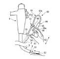
図14に示すように、処置具80は、可撓性の挿入部61の内視鏡1(図1参照)から露出する部分61aに被係合部材51が設けられ、操作部64のハンドル部66にフック81が回転自在に設けられており、この被係合部材51及びフック81が係合手段を構成している。Next, a fifth embodiment of the present invention will be described in detail. In addition, the same code | symbol is attached | subjected to the same component as each said embodiment. Further, the description overlapping with each of the embodiments is omitted.
As shown in FIG. 14, the
フック81は、一部がハンドル部66のつば部82a内に収容されるピン83と、ピン83の先端に取り付けられた先端部84とからなる。
ピン83の基端部には、拡径され、大径部83aが形成されている。
先端部84は、切り欠きによって分岐し、ピン83の長さ方向に平行に延びる2つの係合片85が形成されている。この係合片85間の距離d4は、被係合部材51の最外径d5よりも小さく、引っ掛け部53の外径d6よりは大きい。また、係合片85の厚さは、引っ掛け部53の幅よりも小さい。The
The proximal end portion of the
The
このようなフック81を回転自在に支持するハンドル部66は、先端と基端のそれぞれが拡径し、つば部82a及びつば部82bを形成している。さらに、つば部82aには、フック81の取り付け孔86が設けられている。取り付け孔86は、ハンドル部66の径方向に沿って設けられている。取り付け孔86の外表面の開口部87は、ピン83の外径に略等しい。開口部87よりもハンドル部66の中心寄り部分87bは、ピン83の大径部83aの外径よりも大きい内径を有している。つまり、フック81は、ピン83を開口部87aに摺接させつつ、ピン83の軸回りに回転可能であり、かつ大径部83aによりハンドル部66からの脱離が防止されている。 The
この処置具80は、フック81を、図14に示すような向き、つまりフック81の係合片85が操作部64の長さ方向に沿って配置される向きに設定すると、図15に示すように、被係合部材51の近傍の挿入部61の軸線と、操作部64の軸線とを略直交するように係合させることができる。そして、挿入部61と操作部64とを交差して係合させた状態で、被係合部材51を鉗子口2aに対して進退させるように操作部64を往復移動させると、挿入部61及びブラシ部63が進退し、生体組織が擦過される。
このように、操作部64を、挿入部61に対して交差するような姿勢で操作できるようにすると、自然な姿勢で処置具80の操作を行うことができる。また、操作部64と内視鏡1との干渉を確実に防止できる。As shown in FIG. 15, the
As described above, when the
また、フック81の係合片85が操作部64の周方向に配列される向き、つまり図14に示す向きから、ピン83を中心に90°回転させた向きにフック81の向きを設定すると、前記第四の実施の形態と同様に、操作部64と挿入部61とを略平行に係合させることができる。
さらに、フック81の向きは、前記した2通りの向き以外に設定することも可能である。つまり、患者や、内視鏡1、処置具80の位置や、施術者の嗜好に応じて、操作部64と挿入部61との係合角度を調整することで、内視鏡1及び処置具80の操作を一人で楽に行うことが可能になる。また、挿入部61の湾曲部分に負荷が集中することも防止できる。Further, when the orientation of the
Furthermore, the direction of the
なお、フック81は、底部の両端を平行に立設させた略U字形状の部材と、段付きネジとから構成しても良い。底部に開口を設け、ここに段付きネジの軸部を通して、ネジ部をハンドル部66に締め付ける。開口の径は、段付きネジの軸部の外径に略等しく、頭部の外径よりも小さくする。これにより、段付きネジを回転中心として略U字形状の部材の回転角度を任意に設定することが可能になる。 The
次に、本発明の第六の実施の形態について詳細に説明する。なお、前記各実施の形態と同じ構成要素には同一の符号を付してある。また、前記各実施の形態と重複する説明は省略する。
図16に示すように、この処置具90の係合手段は、操作部に取り付けられた挟持部材91からなる。Next, a sixth embodiment of the present invention will be described in detail. In addition, the same code | symbol is attached | subjected to the same component as each said embodiment. Further, the description overlapping with each of the embodiments is omitted.
As shown in FIG. 16, the engaging means of the
挟持部材91は、操作部64のハンドル部66に固定された固定片92を有している。固定片92は、ハンドル部66の軸線に略直交して配置されている。さらに、固定片92のハンドル部66に固定された基端部から先端部に至るまでの間に、ピン93が固定されており、このピン93には、回動片94が回動自在に支持されている。回動片94は、固定片92と略同じ幅及び厚さを有しており、操作部64の軸線に沿って固定片92と並ぶように配置されている。回動片94においてピン93に支持されている部分よりも基端部側には、弾性部材であるコイルばね95の一端が係合されている。このコイルばね95の他端は、固定片92のピン93よりも基端部側に係合している。このため、回動片94は、コイルばね95によって、その先端部が固定片92の先端部に当接するように、常に付勢されている。 The clamping
この処置具90では、挿入部61の内視鏡1から露出している部分61aであって、内視鏡1の鉗子口2a(図13参照)に近い部分を、固定片92と回動片94とで挟持させる。これにより、挿入部61と操作部64とが交差するように係合するので、操作部64を往復移動させると、挿入部61及びブラシ部63が進退する。 In this
この実施の形態によれば、挟持部材91が挿入部61を挟持することで、操作部64と挿入部61とを確実に係合させるので、ブラシ部63の進退を容易に、かつ確実に行うことができる。したがって、内視鏡1の操作と処置具90の操作とを一人で行うことが可能になる。
ここにおいて、固定片92と回動片94とは、ハンドル部66の周方向に沿って配列されても良い。この場合には、操作部64と挿入部61とが略平行に係合させるようになる。According to this embodiment, since the clamping
Here, the fixed
なお、この発明は、前記各実施の形態に限定されずに広く応用することができる。
例えば、図8に示すような第三の実施の形態における処置具70は、細胞診ブラシであっても良い。この場合には、処置部22がブラシになる。また、図11から図16に示すような第四の実施の形態、第五の実施の形態、第六の実施の形態における処置具60,80,90は、生検鉗子でも良い。この場合には、処置部がブラシ部63の代わりに、支持部材26、一対の生検カップ27、支軸28、及びリンク機構が設けられる。The present invention can be widely applied without being limited to the above embodiments.
For example, the treatment tool 70 in the third embodiment as shown in FIG. 8 may be a cytodiagnosis brush. In this case, the
さらに、各実施の形態において、処置具3,40,50,60,80,90は、複数の弾性把持部材を備える処置部を有しても良い。この弾性把持部材は、基端部が操作ワイヤ24,62に接続され、先端部が爪になっている。そして、操作ワイヤ24,62を前進させたときには、挿入部21,61から突出して拡開し、操作ワイヤ24,62を引き戻したときには、挿入部21,61内に収容されて閉じ、対象物を掴む。このような処置具であっても、係合手段を備えることで、処置部の操作と、進退とを一人で簡単に行えるようになる。 Furthermore, in each embodiment, the
また、図14に示すようなフック81は、つば部82aに固定されていても良い。
図14に示すような回転自在のフック81の代わりに、被係合部材の形状によって、操作部23,64と挿入部21,61とを交差して係合させるようにしても良い。例えば、図7に示すような引っ掛け部44に対して、操作部23と挿入部21とが交差する向きにフック42を係合させても良い。
さらに、フック36,42,52,69,81を挿入部21,61に取り付け、被係合部材25,41,51又はフック36,42,52,69,81に係合する引っ掛け部44,53を操作部23,64に設けても良い。そして、挟持部材91を挿入部61に設けても良い。Further, the
Instead of the
Further, the
1 内視鏡
2 処置具挿通チャンネル(チャンネル)
3,40,50 処置具(生検鉗子)
20 シース
21 挿入部
21a 部分(露出する部分)
22 処置部
23 操作部
25,51 被係合部材(係合手段,第二係合部材)
29 スライダ(保持部分)
36,42,52,69,81 フック(係合手段,第一係合部材)
41 被係合部材(係合手段)
60,80,90 処置具(細胞診ブラシ)
66 ハンドル部(保持部材)
91 挟持部材(係合手段)
d1,d5 大径部の外径
d3,d4 切り欠きの幅
1
3, 40, 50 Treatment tool (biopsy forceps)
20
22
29 Slider (holding part)
36, 42, 52, 69, 81 Hook (engagement means, first engagement member)
41 engaged member (engaging means)
60, 80, 90 Treatment tool (cytodiagnosis brush)
66 Handle part (holding member)
91 Nipping member (engaging means)
d1, d5 Outer diameter of large diameter part d3, d4 Notch width
Claims (9)
Translated fromJapanese前記挿入部の基端部に設けられ、前記内視鏡のチャンネル内に配置した前記挿入部を前記挿入部の基端部と共に前記チャンネルに対して進退させる操作部と、
前記挿入部の基端よりも前記操作部の基端部側に配置されているとともに前記操作部に形成された係合部と、前記挿入部において前記内視鏡の鉗子口から露出する部分とを係合させることによって、前記挿入部に対して前記挿入部の長軸方向に前記操作部を位置決めする係合手段と、
を有することを特徴とする内視鏡用処置具。An insertion section that can be inserted into the channel of the endoscope;
An operation unit that is provided at a proximal end portion of the insertion portion and moves the insertion portion disposed in the channel of the endoscope with respect to the channel together with the proximal end portion of the insertion portion;
An engagement portion that is disposed on the proximal end side of the operation portion with respect to the proximal end of the insertion portion and formed on the operation portion, and a portion that is exposed from the forceps opening of the endoscope in the insertion portion, Engaging means for positioning the operation part in the longitudinal direction of the insertion part with respect to the insertion part by engaging
An endoscopic treatment tool comprising:
前記操作部と前記処置部とのそれぞれに連結され、前記挿入部に沿って配置され、前記処置部を動作可能な操作ワイヤと、 An operation wire connected to each of the operation unit and the treatment unit, arranged along the insertion unit, and capable of operating the treatment unit,
をさらに有し、 Further comprising
前記操作部は、前記挿入部と前記ワイヤとを相対的に動作可能であることを特徴とする請求項1に記載の内視鏡用処置具。 The endoscopic treatment tool according to claim 1, wherein the operation unit is capable of relatively moving the insertion unit and the wire.
Priority Applications (5)
| Application Number | Priority Date | Filing Date | Title |
|---|---|---|---|
| JP2004030651AJP4481029B2 (en) | 2004-02-06 | 2004-02-06 | Endoscopic treatment tool |
| DE602005007576TDE602005007576D1 (en) | 2004-02-06 | 2005-02-01 | TREATMENT DEVICE FOR AN ENDOSCOPE |
| EP05709555AEP1712195B1 (en) | 2004-02-06 | 2005-02-01 | Treating device for endoscope |
| PCT/JP2005/001409WO2005074818A1 (en) | 2004-02-06 | 2005-02-01 | Treating device for endoscope |
| US11/446,995US8353815B2 (en) | 2004-02-06 | 2006-06-05 | Instrument for an endoscope |
Applications Claiming Priority (1)
| Application Number | Priority Date | Filing Date | Title |
|---|---|---|---|
| JP2004030651AJP4481029B2 (en) | 2004-02-06 | 2004-02-06 | Endoscopic treatment tool |
Publications (2)
| Publication Number | Publication Date |
|---|---|
| JP2005218690A JP2005218690A (en) | 2005-08-18 |
| JP4481029B2true JP4481029B2 (en) | 2010-06-16 |
Family
ID=34836008
Family Applications (1)
| Application Number | Title | Priority Date | Filing Date |
|---|---|---|---|
| JP2004030651AExpired - LifetimeJP4481029B2 (en) | 2004-02-06 | 2004-02-06 | Endoscopic treatment tool |
Country Status (5)
| Country | Link |
|---|---|
| US (1) | US8353815B2 (en) |
| EP (1) | EP1712195B1 (en) |
| JP (1) | JP4481029B2 (en) |
| DE (1) | DE602005007576D1 (en) |
| WO (1) | WO2005074818A1 (en) |
Families Citing this family (16)
| Publication number | Priority date | Publication date | Assignee | Title |
|---|---|---|---|---|
| US20060135846A1 (en)* | 2004-12-17 | 2006-06-22 | Hunt John V | Endoscopic device and component attachable to an endoscope handpiece |
| KR101477133B1 (en)* | 2006-06-13 | 2014-12-29 | 인튜어티브 서지컬 인코포레이티드 | Minimally invasive surgical system |
| US8585651B2 (en)* | 2008-05-22 | 2013-11-19 | Terumo Kabushiki Kaisha | Catheter retaining tool |
| JP5407036B2 (en)* | 2008-09-02 | 2014-02-05 | オリンパスメディカルシステムズ株式会社 | Treatment endoscope |
| US10912699B2 (en) | 2012-01-10 | 2021-02-09 | Alessio Pigazzi | Method of securing a patient onto an operating table when the patient is in a position such as the trendelenburg position and apparatus therefor including a kit |
| CN103654942B (en)* | 2012-09-25 | 2015-11-25 | 天津博朗科技发展有限公司 | With the disposable endoscope mirror sheath of surgical instrument angle adjustment device |
| JP6427109B2 (en)* | 2013-12-13 | 2018-11-28 | 国立大学法人九州大学 | Bending treatment tool |
| JP6234267B2 (en)* | 2014-02-21 | 2017-11-22 | オリンパス株式会社 | Surgical manipulator operating device and surgical manipulator system |
| US10194893B2 (en) | 2014-09-26 | 2019-02-05 | BostonScientific Scimed, Inc. | Medical retrieval systems and related methods |
| US10080488B2 (en) | 2014-12-12 | 2018-09-25 | Medix3d LLC | Cleaning device for cleaning a scope, laparoscope or microscope used in surgery or other medical procedures and a method of using the device during surgical or other medical procedures |
| CN109069169B (en)* | 2016-05-06 | 2021-07-20 | 波士顿科学医学有限公司 | Medical systems, devices and related methods |
| US10779715B2 (en)* | 2017-02-23 | 2020-09-22 | Sony Olympus Medical Solutions Inc. | Endoscope apparatus |
| DE102017107546A1 (en)* | 2017-04-07 | 2018-10-11 | Ovesco Endoscopy Ag | Endoscope with additional external working channel |
| US11185215B2 (en)* | 2017-08-07 | 2021-11-30 | Boston Scientific Scimed, Inc. | Medical systems, devices, and related methods |
| IT201800004478A1 (en)* | 2018-04-13 | 2019-10-13 | CONTROL SYSTEM FOR MEDICAL DEVICE THAT CAN BE USED IN THE CONTEXT OF AN ENDOSCOPE. | |
| US11723631B2 (en)* | 2020-04-10 | 2023-08-15 | Orlando Health, Inc. | Brush for non-invasive biopsy |
Family Cites Families (20)
| Publication number | Priority date | Publication date | Assignee | Title |
|---|---|---|---|---|
| JPH01165006A (en) | 1987-12-21 | 1989-06-29 | Akai Electric Co Ltd | Production of magnetic head |
| JPH02224651A (en) | 1989-02-27 | 1990-09-06 | Olympus Optical Co Ltd | Cell picking appliance for endoscope |
| JPH0353211A (en) | 1989-07-21 | 1991-03-07 | Nec Corp | Mechanical optical switch |
| US5150715A (en)* | 1990-04-18 | 1992-09-29 | Fuji Photo Optical Co., Ltd. | Ultrasound-imaging diagnostic system |
| US5695491A (en)* | 1994-11-22 | 1997-12-09 | Washington Research Foundation | Endoscopic accessory and containment system |
| AU6158196A (en)* | 1995-06-07 | 1996-12-30 | Robert T. Chilcoat | Articulated endospcope with specific advantages for laryngos copy |
| JPH0994253A (en)* | 1995-09-29 | 1997-04-08 | Asahi Optical Co Ltd | Endoscope treatment device fixing device |
| US5964740A (en)* | 1996-07-09 | 1999-10-12 | Asahi Kogaku Kogyo Kabushiki Kaisha | Treatment accessory for an endoscope |
| US6004263A (en)* | 1996-03-13 | 1999-12-21 | Hihon Kohden Corporation | Endoscope with detachable operation unit and insertion unit |
| JP3574530B2 (en)* | 1996-05-13 | 2004-10-06 | ペンタックス株式会社 | Endoscope treatment tool guide |
| US5904647A (en)* | 1996-10-08 | 1999-05-18 | Asahi Kogyo Kabushiki Kaisha | Treatment accessories for an endoscope |
| US5876913A (en) | 1997-05-28 | 1999-03-02 | Eastman Kodak Company | Dual-coated radiographic elements with limited hydrophilic colloid coating coverages |
| JPH1176244A (en) | 1997-09-08 | 1999-03-23 | Olympus Optical Co Ltd | Treating device for endoscope |
| US6273882B1 (en)* | 1998-06-18 | 2001-08-14 | Scimed Life Systems | Snap handle assembly for an endoscopic instrument |
| US6743185B2 (en)* | 2000-09-26 | 2004-06-01 | Scimed Life Systems, Inc. | Handle assembly for surgical instrument and method of making the assembly |
| JP4838945B2 (en)* | 2001-05-10 | 2011-12-14 | オリンパス株式会社 | Endoscopic treatment tool and operation part of endoscope treatment tool |
| JP2004049891A (en)* | 2002-05-29 | 2004-02-19 | Olympus Corp | Endoscope apparatus |
| US7179223B2 (en)* | 2002-08-06 | 2007-02-20 | Olympus Optical Co., Ltd. | Endoscope apparatus having an internal channel |
| JP4547184B2 (en)* | 2003-07-29 | 2010-09-22 | オリンパス株式会社 | Endoscope adapter and endoscope |
| US7708756B2 (en)* | 2003-09-29 | 2010-05-04 | Ethicon Endo-Surgery, Inc. | Actuation mechanism for flexible endoscopic device |
- 2004
- 2004-02-06JPJP2004030651Apatent/JP4481029B2/ennot_activeExpired - Lifetime
- 2005
- 2005-02-01EPEP05709555Apatent/EP1712195B1/ennot_activeExpired - Lifetime
- 2005-02-01DEDE602005007576Tpatent/DE602005007576D1/ennot_activeExpired - Lifetime
- 2005-02-01WOPCT/JP2005/001409patent/WO2005074818A1/enactiveIP Right Grant
- 2006
- 2006-06-05USUS11/446,995patent/US8353815B2/ennot_activeExpired - Fee Related
Also Published As
| Publication number | Publication date |
|---|---|
| JP2005218690A (en) | 2005-08-18 |
| US20060224041A1 (en) | 2006-10-05 |
| WO2005074818A1 (en) | 2005-08-18 |
| US8353815B2 (en) | 2013-01-15 |
| EP1712195A4 (en) | 2006-11-08 |
| EP1712195A1 (en) | 2006-10-18 |
| EP1712195B1 (en) | 2008-06-18 |
| DE602005007576D1 (en) | 2008-07-31 |
Similar Documents
| Publication | Publication Date | Title |
|---|---|---|
| US8353815B2 (en) | Instrument for an endoscope | |
| JP4980777B2 (en) | Endoscopic treatment tool | |
| JP5161681B2 (en) | Endoscopic treatment tool | |
| JP4472362B2 (en) | Endoscopic treatment tool | |
| JP5164553B2 (en) | Surgical treatment device | |
| US9277932B2 (en) | Endoscopic scissors instrument with friction enhancing tissue stops | |
| US20100298638A1 (en) | Endoscopic Instrument with Bi-Laterally Widened Cam-Slot at End Effector | |
| JP6290376B2 (en) | Surgeon-controlled endoscopic device | |
| US20210093163A1 (en) | Endoscope with integrated tissue acquisition capability | |
| JP2009273890A (en) | Endoscopic apparatus | |
| JP4323375B2 (en) | Endoscopic treatment tool and endoscope system | |
| JP2003210399A (en) | Endoscope | |
| US20190269306A1 (en) | Fixing device for endoscope | |
| JP6996000B2 (en) | Endoscope system | |
| US11612390B2 (en) | Suturing closure scope with alternative needle orientation | |
| JP6071361B2 (en) | Medical instruments | |
| JP5231169B2 (en) | Treatment instrument, endoscope and endoscope system | |
| JP2005319164A (en) | Treatment appliance for endoscope | |
| JP2005237431A (en) | Treatment tool for endoscope | |
| KR102797287B1 (en) | Endoscopic treatment device with easy rotation of the gripper | |
| EP3518723B1 (en) | A set comprising an endoscope and a work tool unit | |
| JP2517159Y2 (en) | Endoscope treatment tool | |
| WO2017119080A1 (en) | Endoscopy treatment instrument | |
| WO2021176636A1 (en) | Needle holder for endoscope, and endoscopic suturing method | |
| KR20220076619A (en) | Case-separated type endoscope forceps assembly |
Legal Events
| Date | Code | Title | Description |
|---|---|---|---|
| A621 | Written request for application examination | Free format text:JAPANESE INTERMEDIATE CODE: A621 Effective date:20070111 | |
| A131 | Notification of reasons for refusal | Free format text:JAPANESE INTERMEDIATE CODE: A131 Effective date:20091124 | |
| A521 | Request for written amendment filed | Free format text:JAPANESE INTERMEDIATE CODE: A523 Effective date:20100125 | |
| A521 | Request for written amendment filed | Free format text:JAPANESE INTERMEDIATE CODE: A821 Effective date:20100126 | |
| TRDD | Decision of grant or rejection written | ||
| A01 | Written decision to grant a patent or to grant a registration (utility model) | Free format text:JAPANESE INTERMEDIATE CODE: A01 Effective date:20100216 | |
| A01 | Written decision to grant a patent or to grant a registration (utility model) | Free format text:JAPANESE INTERMEDIATE CODE: A01 | |
| A61 | First payment of annual fees (during grant procedure) | Free format text:JAPANESE INTERMEDIATE CODE: A61 Effective date:20100317 | |
| FPAY | Renewal fee payment (event date is renewal date of database) | Free format text:PAYMENT UNTIL: 20130326 Year of fee payment:3 | |
| FPAY | Renewal fee payment (event date is renewal date of database) | Free format text:PAYMENT UNTIL: 20140326 Year of fee payment:4 | |
| S531 | Written request for registration of change of domicile | Free format text:JAPANESE INTERMEDIATE CODE: R313531 | |
| R350 | Written notification of registration of transfer | Free format text:JAPANESE INTERMEDIATE CODE: R350 | |
| R250 | Receipt of annual fees | Free format text:JAPANESE INTERMEDIATE CODE: R250 |