JP4480221B2 - Mist sauna equipment - Google Patents
Mist sauna equipmentDownload PDFInfo
- Publication number
- JP4480221B2 JP4480221B2JP2000092117AJP2000092117AJP4480221B2JP 4480221 B2JP4480221 B2JP 4480221B2JP 2000092117 AJP2000092117 AJP 2000092117AJP 2000092117 AJP2000092117 AJP 2000092117AJP 4480221 B2JP4480221 B2JP 4480221B2
- Authority
- JP
- Japan
- Prior art keywords
- mist
- hot air
- sauna
- spraying
- temperature
- Prior art date
- Legal status (The legal status is an assumption and is not a legal conclusion. Google has not performed a legal analysis and makes no representation as to the accuracy of the status listed.)
- Expired - Fee Related
Links
- 239000003595mistSubstances0.000titleclaimsdescription126
- 238000005507sprayingMethods0.000claimsdescription36
- 238000007664blowingMethods0.000claimsdescription31
- 239000007921spraySubstances0.000description15
- XLYOFNOQVPJJNP-UHFFFAOYSA-NwaterSubstancesOXLYOFNOQVPJJNP-UHFFFAOYSA-N0.000description12
- 230000035900sweatingEffects0.000description11
- 210000004243sweatAnatomy0.000description8
- 210000002414legAnatomy0.000description7
- 210000000689upper legAnatomy0.000description6
- 238000009423ventilationMethods0.000description5
- 238000010438heat treatmentMethods0.000description4
- 238000010586diagramMethods0.000description3
- 230000007613environmental effectEffects0.000description3
- 238000002360preparation methodMethods0.000description3
- 238000005406washingMethods0.000description3
- 230000000694effectsEffects0.000description2
- 210000003141lower extremityAnatomy0.000description2
- 238000000034methodMethods0.000description2
- 238000004458analytical methodMethods0.000description1
- 238000003287bathingMethods0.000description1
- 230000003796beautyEffects0.000description1
- 230000017531blood circulationEffects0.000description1
- 238000004364calculation methodMethods0.000description1
- 238000009833condensationMethods0.000description1
- 230000005494condensationEffects0.000description1
- 238000012790confirmationMethods0.000description1
- 238000011161developmentMethods0.000description1
- 238000007599dischargingMethods0.000description1
- 230000017525heat dissipationEffects0.000description1
- 238000011835investigationMethods0.000description1
- 238000004519manufacturing processMethods0.000description1
- 230000004060metabolic processEffects0.000description1
- 210000005036nerveAnatomy0.000description1
- 238000012546transferMethods0.000description1
- 239000002699waste materialSubstances0.000description1
Images


Landscapes
- Bathtubs, Showers, And Their Attachments (AREA)
- Devices For Medical Bathing And Washing (AREA)
Description
Translated fromJapanese【0001】
【発明の属する技術分野】
本発明は、吸込口より吸込んだ気流を加熱して吹出口より吹出す温風発生手段と、ミストを噴霧するミスト噴霧手段とを備えたミストサウナ装置に関する。
【0002】
【従来の技術】
ミストサウナ装置は、例えば、家庭の浴室等に設置され、浴室をミストサウナとすることができる。ミストサウナは、発汗によって新陳代謝を高め、汗といっしょに老廃物を排出する効能を有し、美容と健康に良いことからも愛好者が多い。
一般に、サウナは、高温サウナ(温度90〜120℃、相対湿度10〜30%)、低温サウナ(温度40〜50℃、相対湿度80〜100%)の他、遠赤外照射(温度40〜60℃、相対湿度10〜30%)に分類されるが、ミストサウナにあっては、前記の低温サウナ状態に環境が設定される。
通常、浴室をミストサウナとして使用する場合は、温風発生手段とミスト噴霧手段とを同時に働かせて、浴室内を、上述の温・湿度状態とする。
【0003】
【発明が解決しようとする課題】
発明者らは、温風発生手段とミスト噴霧手段とを所定の装置本体内に備えた一体型のミストサウナ装置を提案している。このようなミストサウナ装置は、浴室等の比較的低い位置(例えば浴室カウンタの袖部)に設置されて使用されることを予定したものであり、例えば、図2に示される様に、入浴者が椅子等に座った状態で使用することができる。
装置としては、温風の吹出し領域の上部側にミストを吹出す構造を採用し、温風の保有する熱により、ミストを充分に加熱することを意図している。
即ち、従来、ミストの噴霧領域と温風の吹出し領域との位置関係に関しては、通常、上昇気流となる温風の性質より、温風の吹出領域に対して上側からミストを噴霧し、温風により効率的に蒸気を発生するのが良いと考えられてきた。
また、その吹き出し方向、あるいは噴霧方向は、従来、固定されたものであった。
【0004】
【発明が解決しようとする課題】
しかしながら、実際に、上記のようなミストサウナ装置を、浴室のカウンタの袖部に配置して運転を試みたところ、以下のような問題があることが判明した。
ミストサウナは温水ミストによる湿潤雰囲気で、発汗させることを意図しているが、温風の吹出し領域に対してその上側からミストを噴霧すると、温風全体で高温ミストを発生されることとなるため、温風の吹出し領域が、人の肩部付近にあると、湿潤雰囲気が直接、人の頭部にあたり、頭部において、汗とミストの結露が発生し、髪の毛がベトつき、不快となりやすい。
さらに、使用者によって、温風もしくは高温ミストの当たる位置に関して、好ましいと思う上下方向位置に、かなり差がある。
また、後にも示すように、発汗効果を主に考えた場合、ミストを伴った温風の吹き付け領域は、人体の下肢部に近いほうが効果が高いことが判明した。しかしながら、従来型のミストサウナ装置では、このような下肢部を中心としてサウナ効果を発揮する構造を積極的に採用するとは言えず、装置的に充分なものと言えない。
本発明の目的は、温風発生手段とミスト噴霧手段とを備えたミストサウナ装置おいて、上記のような問題を解消できるミストサウナ装置を得ることである。
【0005】
【課題を解決するための手段】
この目的を達成するための本発明によるミストサウナ装置の特徴構成は、
請求項1に記載されているように、
吸込口より吸込んだ気流を加熱して吹出口より温風として吹出す温風発生手段と、ミストを水平方向に層状に噴霧するミスト噴霧手段とを備え、温風発生手段とミスト噴霧手段とを同時に働かせて、所定の温・湿度状態のサウナ空間とするミストサウナ装置であって、
温風発生手段の吹出口が設置状態で水平方向の長手軸を有する開口とされる共に、ミスト噴霧手段のミスト噴霧部が吹出口に対して下側に設けられ、長手軸方向で長くなる温風吹出し領域に対して、ミストを下側から供給することにある。
この装置にあっては、従来型のものと比較して、温風の吹出し領域とミストの噴霧領域との領域位置関係が上下逆転する。即ち、水平方向で長い状態に吹出される温風の吹出し領域の下側にミスト域が形成される。さて、後にも示す様に、ミストサウナを充分快適な状態で使用し、なおかつ、充分な発汗量を確保しようとすると、温風を伴った湿潤雰囲気を、人の下半身側に当てるのが最も好ましい。
さらに、通常、ミストサウナ装置にあっては、少なくとも温風が頭部より下の人体部位に当たるように設置するのが常であるが、温風の当たる人体部位と、ミストを含む湿潤雰囲気が当たる人体部位との位置関係は、本願装置にあって、前者を上側となり、これが水平方向で横長状となるため、結果的に、頭部付近の相対湿度を低下でき、髪のべたつきが少ない快適なミストサウナ環境を実現できる。顔面にミストが当たり難いようにすることで、汗とミストが顔面に混在しないようにできるため、快適感が増す。
同時に、温風吹出し領域より下の領域に、比較的湿度の高いミストサウナ領域を形成できる。
【0006】
さて、上記のミストサウナ装置にあって、請求項2に記載されているように、前記温風発生手段に備えられる温風発生側揺動部材の揺動により、前記温風吹出し方向が上下方向で変えられることが好ましい。
この装置の場合は、温風の吹出し領域を揺動部材の揺動に応じて、吹出し方向を上下方向で変えられるため、ミストサウナの使用者の状況、頭部、肩部の位置と吹出口の上下位置関係等によって、温風が当たる人体部位を適切に調整できる。
【0007】
更に、上記したミストサウナ装置の構成にあって、請求項3に記載されているように、前記ミスト噴霧手段に備えられるミスト側揺動部材の揺動により、前記ミストの噴霧方向が上下方向で変えられるように構成されていることが好ましい。
このようにしておくと、概略、上側に形成されている温風の吹出し領域に対して、ミストの噴霧領域を、温風とミストとが平行に吹出されている状態、ミストが温風の吹出し領域に向けて交差されて上方に吹出されている状態、ミストが温風の吹出し領域から離間する下方に吹出されている状態等を実現でき、結果的に、使用者の好む状態でミストサウナを楽しめる。
また、温風の吹出し領域の場合と同様に、使用者にとって好ましい方向に、ミストの噴霧領域を選択することが可能となる。
更に、例えば、温水ミストを温風に向けてやや上向きに噴霧して高温のミストサウナを楽しんだ後、ミスト噴霧手段より冷水ミストを噴霧させる状態とし、ミストの噴霧方向を下向きとして、人の足の甲に当てるような使用形態とすると、自立神経の活性化に役立ち、入浴後の放熱を抑制することが可能となる。
【0008】
【発明の実施の形態】
図1は、本発明に係るミストサウナ装置3を浴室1に設置した状態を示している。
浴室1内には、浴槽6と洗場7があり、浴槽6に湯を張り、洗場7において、体を洗うことができる。ミストサウナ装置3が、浴室1の内側の側壁下方部(例えば、浴室1内の高さの2分の1程度下方部で具体的には洗い場カウンタ30の袖部)に備えられており、浴室1をミストサウナとして利用できる。
この様にミストサウナ装置3を側壁下方部に備えることで、例えば温風が頭上から吹出して「頭がボーとする」等の問題がなく、足元から、温風を吹出し、快適に加温することができる。
【0009】
浴室1の側壁の上方には、浴室1内の換気を行う換気扇4が備えられており、換気扇4はミストサウナ装置3に備えられた制御装置100(この中には制御手段Cが格納されている)によって制御される。
又、図に示していない脱衣場のドア8の側部に、ミストサウナ装置3の制御装置100と接続されるリモコン5が備えられており、制御装置100に運転指示を与えることができる。
【0010】
以上が、浴室1の概略的な構成であり、以下に、浴室1をミストサウナとして利用可能とするミストサウナ装置3について詳細を説明する。
装置3は、温風を吹出す吹出口12と浴室1内の空気を吸込む吸込口13が備えられており、吸込口13から吸込んだ空気を吹出口12より吹出す為のファン(図示せず)を内部に備えている。更に、吸込口13より吸込んだ空気を加熱する熱交換器(図示せず)を備えており、熱交換器に湯水を供給し、この湯水と空気の熱交換を行い空気を加熱する構成となっている。従って、吹出口12からは、加熱された温風が吹出される。
温風の吹出口12は、設置状態で概略水平とされ、内部を温風が流れる温風発生側揺動部材12aに、水平方向に分散して設けられており(結果、吹出口12は揺動部材12aの長手方向に長手軸を有する開口となっている)、概略、水平、層状に温風を吹出す。更に、この温風発生側揺動部材12aが、その水平な軸周りに揺動可能に構成されていることにより、層状に吹出される温風の吹出し方向を上下方向に揺動できる。このようにして本願の温風発生手段Hが構成されている。
【0011】
この構成において、上記のファンの回転数を変更することで、吹出口12から吹出される温風の流量を変更することができ、本願に言うサウナ空間2を流れる気流の流速を設定することができる。このようなサウナ空間2における気流速度の制御は、制御装置100に備えられた制御手段Cによる温風の吹出し速度の制御による。
【0012】
更に、上記の熱交換器に供給する湯水の量、若しくは温度を調整することで吹出口12から吹出される空気の温度を変更することができ、浴室1内のサウナ空間2の温度を設定することができる。このようなサウナ空間2における温度の制御も、前記制御手段Cによる。
【0013】
ミストサウナ装置3はミストを噴霧するミスト噴霧機構11を備えており、このミスト噴霧機構11に供給する湯水の量を設定することができる。
このミスト噴霧機構11にあっても、設置状態で概略水平とされ、内部をミストが流れるミスト側揺動部材11aが備えられると共に、この揺動部材11aに水平方向で分散してミストノズル10が備えられている。即ち、複数のミストノズル10によりミスト噴霧部が構成されている。従って、ミストは水平方向に概略末広がり層状に噴霧されると共に、揺動部材11aの揺動に従って、その噴霧方向を上下方向で変更可能である。このようにして本願のミスト噴霧手段Mが構成されている。
【0014】
図1(ロ)に示すように、ミストノズル10の位置が温風の吹出口12より低い位置に設けられていることより、その噴霧始点あるいはその近傍において、ミストの噴霧領域は、温風の吹出し領域に対して下側とされている。
噴霧した湯水のミストは噴霧された後に蒸発し、浴室1内の湿度を上昇させる。この噴霧量を設定することでサウナ空間2の湿度を設定することろなる。このようなサウナ空間2における湿度の制御も、制御手段Cによるミスト噴霧量の制御による。このミストの温度も、温水の温度制御により可能である。
【0015】
尚、サウナ空間2とは、サウナ運転時に人が存在する空間のことを示し、図に示すような浴室1においては、洗場7における周囲壁面よりも20cm程度内側で、洗場7の底板の上方で、人の頭頂までの空間をサウナ空間2とすることができる。この場合、人は立位で考える。
【0016】
快適且つ発汗性の良いサウナを実現する為には、サウナ空間2の気流、温度、湿度を最適な範囲に設定することが重要である。
そこで、ミストサウナ装置3において、サウナ運転時に、制御手段Cは、前記サウナ空間2を流れる気流の流速を0.8〜2m/sに設定し、温度を40〜50℃に設定し、湿度を80〜100%に設定する。
尚、浴室1の容積及び形状等は既知の条件であり、サウナ空間2において所定の気流の流速、温度、湿度に設定する為の、吹出口12における温風の温度および吹出し量、ミストノズル10におけるミストの温度及び噴霧量の設定量は、浴室1に備えられる温度・湿度センサ14の検出値と目標値との関係で予め求めておくことができ、制御手段Cは、サウナ空間2が目標量の環境状態になるように、設定量を定めるように働く構成とされている。
【0017】
即ち、図1に示すミストサウナ装置3は、浴室1内の温度及び湿度を検出する温度・湿度センサ14を備えており、サウナ運転時に、そのセンサ14の出力信号に基づいて、浴室1内を一定温度、例えば,40℃、湿度80%程度、サウナ空間2の気流の速度を1m/sに設定することができる。
一例として、この状態に、制御手段Cがサウナ空間2を設定する手順について以下説明する。
まず、リモコン5等によってサウナ運転開始の指示を得た制御手段Cは、サウナ空間2においての気流の流速が1.0m/s程度の温風を浴室1のサウナ空間2に循環させて加温する。
又、このサウナ空間2の加温と同時、若しくはその前後に、即ち、ミスト噴霧機構11より湯水のミストの噴霧を開始する。この場合、目標温度は設定されるため、この温度を守れるように、温風の吹出し状態を対照しながら、ミスト噴霧機構11からの噴霧量を制御する。即ち、浴室1の形状、容積等の条件が予め決まっているため、湯水のミストを噴霧して、湿度を80%程度まで加湿する準備時間とその噴霧量とが予め判明しており、制御手段Cはその予め判明している噴霧量及び準備時間に従って、サウナ空間2の温度を40℃にできるだけ保ちながら、湿度が80%程度になるまでミストを噴霧して加湿し、サウナ空間2の湿度が80%になるとミストを停止する。
このような制御を行うことで、準備時間後のサウナ空間2を流れる気流の流速は1.0m/s程度、温度は40℃、湿度は80%程度に設定され、サウナ空間2において、「息苦しい」、「髪がべとべとする」等がなく、更に快適で発汗性の良いサウナを実現することができる。
【0018】
次に、ミストサウナとして使用する場合の好ましい使用状態、さらにはサウナ空間において実現すべき好ましい環境状態に関して、発明者らが検討した結果に関して説明する。
1 温風及びミストにより、人体のどの部位を温風により加熱すべきか
この検討は、人体のどの部位に温風を当てた場合に、発汗量、人体の深部温、平均皮膚温がどのようになるかを検討したものである。
検討に当たっては、発明者らが開発した人体熱モデル(日本機械学会論文集、61巻、584号、B編、人体熱モデルの開発、竹森、中島、庄司)を使用した。このモデルを使用すると、人体周りの熱環境(温度、湿度、気流速度等)を設定することで、人体各部位における発汗量、深部温度、平均皮膚温を求めることができる。ちなみに、このモデルは人体を、図4に示すような15個の円筒形熱モデルで代表するものであり、各円筒形熱モデル間で血流移動に伴う熱移動が定義されており、人体は任意の姿勢をとることが可能となっている。
人体付近における気流速度としては、温風が直接当たる部位では1.5m/s,温風が直接当たらない部位では0.2m/sの気流を用い、温風温度40℃、湿度100%とした。
ただし、温風が当たるのは、表1に示す3状態において、それぞれ、頭部(表1において頭部気流と記載)、胴体部(表1において胴体部気流と記載)、脚部(表1において脚部気流と記載)とし、人体の前面片面のみとした。
このような検討をおこなった結果は、以下の表1の通りである。
【0019】
【表1】
上記の結果から、温風を当てる部位としては、脚部が最も効果的であることが判る。
更に、温風が当たる部位を変化させて、脚部のどこが効果的かの検討を行なった結果を表2に示す。表2にあっては、脚部のうち、大腿、下腿、足に、それぞれ単独で、温風を当てるものとした。
【0021】
【表2】
この結果から、発汗量には大きな差はないが、表面積(大腿(1482cm2)、下腿(1024cm2)、足(586cm2))との関係から考えると足が最も効果的であることが判る。
更に、脚部の、足から順次上側に温風吹きつけ部を増加させていった場合(1)足のみ、2)足と下腿、3)足、下腿及び大腿、4)足、下腿、大腿及び手)に、どこまでを加温すべきかの問題に対する結果に関しては、以下の表3に示す結果を得た。
【0023】
【表3】
上記の結果から、足に下腿を加えると発汗量は10%増加、大腿まで含めると24%増加、さらに手を加えると増加する。
よって、下から順次、上へ、湿潤温風を当てるのが良い。
以上の検討の結果から、本願のようなミストサウナ装置を、浴室の比較的下側の部位に配設し、人体の大腿より下側の部位に、温風及びミストを当てるのが良い。
【0025】
2 環境条件と気流の速度の関係
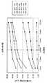
図3に、サウナ空間を流れる気流の流速、温度、湿度と人体の皮膚表面からの発汗量との関係を数値計算できる人体熱モデルによる、10分間の発汗量についての数値解析結果のグラフを示す。
この計算結果より、サウナ空間を流れる気流の流速と発汗量の関係はほぼ比例関係にあることがわかる。更に、十分な発汗量を確保しようとすると、温湿度が45℃以上、80%以上であることが好ましく、流速を増やすに連れて、発汗量が増加していることがわかる。この流速は0.8m/s以上が好ましい。
このような手法によって、短時間でより発汗でき、快適なミストサウナの条件を得ることができる。
【0026】
上述したように、ミストサウナ装置3は換気扇4を制御することができ、例えば、サウナ運転終了後に、換気扇4を駆動させ、浴室1内の湿気を外部に放出して湿度を下げ、浴室1内をからっとさせる浴室換気機能を発揮できる。
【0027】
以上のように適切なミストサウナの運転条件が決まるが、本願のように温風の層の下側にミストを吹出すことの利点は実験的にも確認できた。
即ち、温風の吹出しと、浴室のコーナーに縦型配置されるミストノズルを備えた装置と、本願装置とを比較し、図2に示す姿勢での、髪の毛の含水率を確認したところ、従来構造のもので、25%程度髪の含水率が増加したのに対して、本願構成のものでは、6%程度に止まった。
ここで、含水率の確認は、図2に示す人の頭部位置に、髪の毛に模したかつらを配設し、このかつらの含水率を調べることで、確認できた。
【0028】
〔別実施の形態〕
上記の実施の形態においては、温風発生手段からの温風の吹出し方向及びミスト噴霧手段からのミスト噴霧方向の両方を上下方向で変更可能としたが、いずれか一方でも良い。また、その揺動機構としては、従来、公知の任意の構造を採用できる。
【図面の簡単な説明】
【図1】本発明に係るミストサウナ装置の配置状態及び構成を示す図
【図2】人体と温風及びミストの上下関係を示す図
【図3】サウナ空間を流れる気流の流速、温度、湿度と人体皮膚表面からの発汗量の関係を示すグラフ
【図4】人体熱モデルの概略構成を示す図
【符号の説明】
1 浴室
2 サウナ空間
3 ミストサウナ装置
11 ミスト噴霧機構
11a ミスト側揺動部材
12 吹出口
12a 温風発生側揺動部材
13 吸込口
C 制御手段
H 温風発生手段
M ミスト噴霧手段[0001]
BACKGROUND OF THE INVENTION
The present invention relates to a mist sauna apparatus provided with warm air generating means for heating an airflow sucked from a suction port and blowing it from a blower outlet, and mist spraying means for spraying mist.
[0002]
[Prior art]
For example, the mist sauna device is installed in a bathroom in a home, and the bathroom can be used as a mist sauna. Mist saunas increase metabolism by sweating, have the effect of discharging waste products together with sweat, and are enthusiastic because they are good for beauty and health.
In general, saunas include high-temperature saunas (temperature 90 to 120 ° C.,
Normally, when the bathroom is used as a mist sauna, the hot air generating means and the mist spraying means are simultaneously operated to bring the inside of the bathroom into the above-described temperature / humidity state.
[0003]
[Problems to be solved by the invention]
The inventors have proposed an integrated mist sauna apparatus provided with a warm air generating means and a mist spraying means in a predetermined apparatus body. Such a mist sauna device is intended to be installed and used in a relatively low position such as a bathroom (for example, a sleeve part of a bathroom counter). For example, as shown in FIG. Can be used while sitting on a chair or the like.
The apparatus employs a structure in which mist is blown to the upper side of the hot air blowing region, and is intended to sufficiently heat the mist by the heat held by the hot air.
That is, conventionally, with regard to the positional relationship between the mist spray region and the hot air blowing region, the mist is sprayed from the upper side with respect to the hot air blowing region due to the nature of the warm air that is normally an updraft. It has been considered good to generate steam more efficiently.
Further, the blowing direction or the spraying direction is conventionally fixed.
[0004]
[Problems to be solved by the invention]
However, when the mist sauna apparatus as described above was actually placed on the sleeve of the bathroom counter and the operation was attempted, it was found that there were the following problems.
The mist sauna is intended to sweat in a moist atmosphere with hot water mist, but if mist is sprayed from the upper side of the hot air blowing area, hot mist will be generated in the whole hot air. If the hot air blowing area is in the vicinity of a person's shoulder, the moist atmosphere directly hits the person's head, and sweat and mist condensation occurs on the head, and the hair tends to be sticky and uncomfortable.
Furthermore, depending on the user, there is a considerable difference in the vertical position that is preferable for the position where the hot air or high temperature mist hits.
Further, as will be shown later, when the sweating effect was mainly considered, it was found that the warm air blowing region accompanied with mist is more effective near the lower limbs of the human body. However, in the conventional mist sauna device, it cannot be said that such a structure that exhibits the sauna effect centering on the lower limbs is positively adopted, and it cannot be said that the device is sufficient.
An object of the present invention is to provide a mist sauna device that can solve the above-described problems in a mist sauna device including a hot air generating means and a mist spraying means.
[0005]
[Means for Solving the Problems]
In order to achieve this object,the characteristic configuration of the mist sauna device according to the present inventionis:
As described in
A warm air generating means for heating the airflow sucked from the suction port and blowing it out as warm air from the outlet; and a mist spraying means for spraying the mist in a layered manner in the horizontal direction, comprising the hot air generating means and the mist spraying means. It is a mist sauna device that works at the same time to make a sauna space of a predetermined temperature and humidity state,
While the outlet of the hot air generating means is an opening having a horizontal longitudinal axis in the installed state, the mist spraying portion of the mist spraying means is provided below the outlet and is long in the longitudinal axis direction. The mist is supplied from the lower side to the wind blowing region.
In this apparatus, the region positional relationship between the hot air blowing region and the mist spraying region is reversed upside down as compared with the conventional device. That is, a mist area is formed below the hot air blowing area blown in a long state in the horizontal direction. Now, as will be shown later, when using a mist sauna in a sufficiently comfortable state, and when trying to secure a sufficient amount of perspiration, it is most preferable to apply a humid atmosphere with warm air to the lower body side of the person .
Furthermore, in general, in a mist sauna device, it is usually installed so that at least warm air hits a human body part below the head, but a human body part to which hot air hits and a humid atmosphere containing mist hit. The positional relationship with the human body part is in the device of the present application, and the former is on the upper side, which is horizontally long, and as a result, the relative humidity near the head can be reduced, and the hair is not sticky and comfortable. A mist sauna environment can be realized. By making it hard for mist to hit the face, sweat and mist can be prevented from being mixed on the face, increasing comfort.
At the same time, a mist sauna area with relatively high humidity can be formed in an area below the hot air blowing area.
[0006]
Now, in the mist sauna device described above, as described in
In the case of this apparatus, the blowing direction of the hot air can be changed in the vertical direction according to the swinging of the swinging member, so that the situation of the mist sauna user, the position of the head, shoulder and the outlet It is possible to appropriately adjust the human body part to which the hot air hits depending on the vertical position relationship.
[0007]
Further, in the configuration of the mist sauna device described above, as described in
In this way, the mist spraying region is generally in a state where the warm air and the mist are blown in parallel to the hot air blowing region formed on the upper side, and the mist is blowing out the hot air. It is possible to realize a state in which it is crossed toward the area and blown upward, a state in which the mist is blown downward away from the hot air blowing area, etc. Enjoy it.
Further, as in the case of the hot air blowing region, it is possible to select the mist spraying region in a direction preferable for the user.
Furthermore, for example, after enjoying a hot mist sauna by spraying warm water mist slightly upwards toward the warm air, the cold water mist is sprayed from the mist spraying means, and the spray direction of the mist is directed downward. If the form of use is applied to the instep, it helps to activate the self-supporting nerve and suppresses heat dissipation after bathing.
[0008]
DETAILED DESCRIPTION OF THE INVENTION
FIG. 1 shows a state in which a
In the
By providing the
[0009]
Above the side wall of the
Further, a remote controller 5 connected to the
[0010]
The above is the schematic configuration of the
The
The
[0011]
In this configuration, the flow rate of the warm air blown from the
[0012]
Furthermore, the temperature of the air blown from the
[0013]
The
Even in the
[0014]
As shown in FIG. 1 (b), since the position of the
The sprayed water mist evaporates after being sprayed and raises the humidity in the
[0015]
The
[0016]
In order to realize a comfortable and sweating sauna, it is important to set the airflow, temperature, and humidity in the
Therefore, in the
It should be noted that the volume and shape of the
[0017]
That is, the
As an example, the procedure in which the control means C sets the
First, the control means C which has received an instruction to start sauna operation by the remote controller 5 or the like circulates warm air having a flow velocity of about 1.0 m / s in the
Also, spraying of hot water mist is started from the
By performing such control, the flow velocity of the airflow flowing through the
[0018]
Next, a description will be given of the results of investigations made by the inventors with respect to a preferable use state when used as a mist sauna and a preferable environmental state to be realized in the sauna space.
1. Which part of the human body should be heated with warm air using warm air and mist This study is based on how the sweating amount, the deep part temperature of the human body, and the average skin temperature are affected when hot air is applied to which part of the human body. It is what was examined.
In the examination, a human thermal model developed by the inventors (The Japan Society of Mechanical Engineers, 61, 584, Part B, development of a human thermal model, Takemori, Nakajima, Shoji) was used. If this model is used, the amount of perspiration, the deep temperature, and the average skin temperature in each part of the human body can be obtained by setting the thermal environment (temperature, humidity, air velocity, etc.) around the human body. By the way, this model represents the human body with 15 cylindrical heat models as shown in FIG. 4, and heat transfer associated with blood flow movement is defined between each cylindrical heat model. It is possible to take any posture.
As the air velocity near the human body, an air flow of 1.5 m / s was used in a portion where the hot air was directly applied, and an air flow of 0.2 m / s was used in a portion where the hot air was not directly applied, and the hot air temperature was 40 ° C. and the humidity was 100%. .
However, warm air hits in the three states shown in Table 1, respectively, the head (described as head airflow in Table 1), the body (described as body airflow in Table 1), and the leg (Table 1). In the above description, the airflow is the leg airflow), and only the front surface of the human body is used.
The results of such studies are shown in Table 1 below.
[0019]
[Table 1]
From the above results, it can be seen that the leg is the most effective as the portion to which the hot air is applied.
Further, Table 2 shows the results of examining where the leg portion is effective by changing the part to which the hot air hits. In Table 2, hot air was applied to the thigh, the lower leg, and the leg independently of the legs.
[0021]
[Table 2]
From this result, although there is no great difference in the amount of sweating, it can be seen that the foot is most effective when considered in relation to the surface area (thigh (1482 cm2 ), lower leg (1024 cm2 ), foot (586 cm2 )). .
Furthermore, when the warm air blowing part is increased sequentially from the foot to the upper side of the leg (1) Only the foot, 2) The foot and lower leg, 3) The foot, lower leg and thigh, 4) The foot, lower leg, thigh and As for the results for the problem of how far to be heated, the results shown in Table 3 below were obtained.
[0023]
[Table 3]
From the above results, the amount of sweat increases by 10% when the lower leg is added to the foot, increases by 24% when the thigh is included, and increases when the hand is added.
Therefore, it is better to apply wet warm air from the bottom upward.
As a result of the above examination, it is preferable to dispose a mist sauna apparatus as in the present application in a relatively lower part of the bathroom and apply warm air and mist to a part below the thigh of the human body.
[0025]
2 Relationship between environmental conditions and airflow velocity Figure 3 shows the amount of sweating for 10 minutes using the human body heat model that can numerically calculate the relationship between the flow velocity, temperature, and humidity of the airflow flowing through the sauna space and the amount of sweating from the skin surface of the human body. The graph of the numerical analysis result about is shown.
From this calculation result, it can be seen that the relationship between the flow velocity of the airflow flowing through the sauna space and the amount of sweating is almost proportional. Furthermore, in order to secure a sufficient amount of sweating, it is preferable that the temperature and humidity be 45 ° C. or higher and 80% or higher, and that the amount of sweating increases as the flow rate increases. This flow rate is preferably 0.8 m / s or more.
By such a method, it is possible to sweat more in a short time and to obtain a comfortable mist sauna condition.
[0026]
As described above, the
[0027]
As described above, an appropriate operating condition of the mist sauna is determined, but the advantage of blowing the mist under the hot air layer as in the present application was confirmed experimentally.
That is, when comparing the apparatus with the mist nozzle arranged in the bathroom corner and the mist nozzle vertically arranged in the corner of the bathroom with the apparatus of the present application, and confirming the moisture content of the hair in the posture shown in FIG. With the structure, the moisture content of the hair increased by about 25%, whereas with the structure of the present application, it remained at about 6%.
Here, the confirmation of the moisture content could be confirmed by arranging a wig imitating hair at the human head position shown in FIG. 2 and examining the moisture content of the wig.
[0028]
[Another embodiment]
In the above embodiment, both the hot air blowing direction from the hot air generating means and the mist spraying direction from the mist spraying means can be changed in the vertical direction, but either one may be used. As the swing mechanism, any conventionally known structure can be adopted.
[Brief description of the drawings]
FIG. 1 is a diagram showing the arrangement and configuration of a mist sauna apparatus according to the present invention. FIG. 2 is a diagram showing the vertical relationship between a human body, hot air, and mist. FIG. Graph showing the relationship between the amount of sweat and the amount of sweat from the human skin surface [Fig. 4] Diagram showing the schematic configuration of the human body heat model
DESCRIPTION OF
Claims (3)
Translated fromJapanese前記温風発生手段の吹出口が設置状態で水平方向の長手軸を有する開口とされる共に、前記ミスト噴霧手段のミスト噴霧部が前記吹出口に対して下側に設けられ、前記長手軸方向で長くなる温風吹出し領域に対して、前記ミストを下側から供給するミストサウナ装置。A hot air generating means blows a hot air from the air outlet to heat the air flow sucked from the suction port, and a mist spraying unit for spraying a layer of mist in the horizontal direction,and a hot air generating means and the mist spraying unit It is a mist sauna device thatworks at the same time to make a sauna space of a predetermined temperature and humidity state ,
The outlet of the hot air generating means is an opening having a horizontal longitudinal axis in the installed state, and the mist spraying portion of the mist spraying means is provided below the outlet, and the longitudinal axis direction A mist sauna device that supplies the mist from the lower side to the hot air blowing region that is long in
Priority Applications (1)
| Application Number | Priority Date | Filing Date | Title |
|---|---|---|---|
| JP2000092117AJP4480221B2 (en) | 2000-03-29 | 2000-03-29 | Mist sauna equipment |
Applications Claiming Priority (1)
| Application Number | Priority Date | Filing Date | Title |
|---|---|---|---|
| JP2000092117AJP4480221B2 (en) | 2000-03-29 | 2000-03-29 | Mist sauna equipment |
Publications (2)
| Publication Number | Publication Date |
|---|---|
| JP2001276170A JP2001276170A (en) | 2001-10-09 |
| JP4480221B2true JP4480221B2 (en) | 2010-06-16 |
Family
ID=18607497
Family Applications (1)
| Application Number | Title | Priority Date | Filing Date |
|---|---|---|---|
| JP2000092117AExpired - Fee RelatedJP4480221B2 (en) | 2000-03-29 | 2000-03-29 | Mist sauna equipment |
Country Status (1)
| Country | Link |
|---|---|
| JP (1) | JP4480221B2 (en) |
Families Citing this family (6)
| Publication number | Priority date | Publication date | Assignee | Title |
|---|---|---|---|---|
| JP4654624B2 (en)* | 2004-07-14 | 2011-03-23 | パナソニック株式会社 | Bathroom sauna equipment |
| JP2006280502A (en)* | 2005-03-31 | 2006-10-19 | Osaka Gas Co Ltd | Mist sauna device |
| JP4851750B2 (en)* | 2005-08-31 | 2012-01-11 | 株式会社ハーマン | Mist sauna equipment |
| JP2007271160A (en)* | 2006-03-31 | 2007-10-18 | Tokyo Gas Co Ltd | Steam generator |
| JP5055973B2 (en)* | 2006-11-21 | 2012-10-24 | パナソニック株式会社 | Bathroom sauna equipment |
| CN111728849B (en)* | 2020-07-08 | 2023-09-26 | 黄云山 | Hot-cold scanning physiotherapy cabin and use method thereof |
- 2000
- 2000-03-29JPJP2000092117Apatent/JP4480221B2/ennot_activeExpired - Fee Related
Also Published As
| Publication number | Publication date |
|---|---|
| JP2001276170A (en) | 2001-10-09 |
Similar Documents
| Publication | Publication Date | Title |
|---|---|---|
| US8689820B2 (en) | Pneumatic system for residential use | |
| CN1907252B (en) | Warm bath apparatus | |
| JP2004538114A (en) | Shower room mechanism with body dryer | |
| KR100816645B1 (en) | Wellness Body Dryer and its Control Method | |
| CN101874717B (en) | Bathing body-drying device | |
| JP5092346B2 (en) | Sauna device that suppresses sweating and widens pores | |
| CN102327180B (en) | Multifunctional fumigator | |
| JP2011504109A (en) | Pet animal drying equipment | |
| CN107114897B (en) | A kind of horizontal dry hair massage machine | |
| JP4480221B2 (en) | Mist sauna equipment | |
| WO2022268649A1 (en) | Sauna heating apparatus and method of heating sauna sweat room | |
| CN201384444Y (en) | Bathing and body-drying device | |
| CN206252452U (en) | Foot drying apparatus with hot air | |
| JP4481381B2 (en) | Sauna equipment and its operation method and bathroom ventilation heating dryer | |
| JPH05317377A (en) | Sauna unit | |
| US5987662A (en) | Sauna device | |
| JP2001276167A (en) | Sauna facility and its using method | |
| JP2001276169A (en) | Sauna device | |
| CN212743512U (en) | Even temperature sauna room | |
| CN204219340U (en) | A multifunctional oven steaming equipment | |
| JP6091347B2 (en) | Clothing care equipment | |
| JPH045929Y2 (en) | ||
| CN109223508A (en) | Balance Water therapy cabin | |
| JPH0852192A (en) | Bath apparatus | |
| JP2009082391A (en) | Bathroom mist sauna device |
Legal Events
| Date | Code | Title | Description |
|---|---|---|---|
| RD04 | Notification of resignation of power of attorney | Free format text:JAPANESE INTERMEDIATE CODE: A7424 Effective date:20020905 | |
| A621 | Written request for application examination | Free format text:JAPANESE INTERMEDIATE CODE: A621 Effective date:20060120 | |
| A131 | Notification of reasons for refusal | Free format text:JAPANESE INTERMEDIATE CODE: A131 Effective date:20090312 | |
| A521 | Written amendment | Free format text:JAPANESE INTERMEDIATE CODE: A523 Effective date:20090511 | |
| A131 | Notification of reasons for refusal | Free format text:JAPANESE INTERMEDIATE CODE: A131 Effective date:20091126 | |
| A521 | Written amendment | Free format text:JAPANESE INTERMEDIATE CODE: A523 Effective date:20100122 | |
| TRDD | Decision of grant or rejection written | ||
| A01 | Written decision to grant a patent or to grant a registration (utility model) | Free format text:JAPANESE INTERMEDIATE CODE: A01 Effective date:20100304 | |
| A01 | Written decision to grant a patent or to grant a registration (utility model) | Free format text:JAPANESE INTERMEDIATE CODE: A01 | |
| A61 | First payment of annual fees (during grant procedure) | Free format text:JAPANESE INTERMEDIATE CODE: A61 Effective date:20100316 | |
| FPAY | Renewal fee payment (event date is renewal date of database) | Free format text:PAYMENT UNTIL: 20130326 Year of fee payment:3 | |
| R150 | Certificate of patent or registration of utility model | Ref document number:4480221 Country of ref document:JP Free format text:JAPANESE INTERMEDIATE CODE: R150 Free format text:JAPANESE INTERMEDIATE CODE: R150 | |
| FPAY | Renewal fee payment (event date is renewal date of database) | Free format text:PAYMENT UNTIL: 20130326 Year of fee payment:3 | |
| LAPS | Cancellation because of no payment of annual fees |