JP4479965B2 - Combustion control device - Google Patents
Combustion control deviceDownload PDFInfo
- Publication number
- JP4479965B2 JP4479965B2JP2005128655AJP2005128655AJP4479965B2JP 4479965 B2JP4479965 B2JP 4479965B2JP 2005128655 AJP2005128655 AJP 2005128655AJP 2005128655 AJP2005128655 AJP 2005128655AJP 4479965 B2JP4479965 B2JP 4479965B2
- Authority
- JP
- Japan
- Prior art keywords
- power
- flame
- circuit
- power supply
- combustion
- Prior art date
- Legal status (The legal status is an assumption and is not a legal conclusion. Google has not performed a legal analysis and makes no representation as to the accuracy of the status listed.)
- Expired - Lifetime
Links
Images

Landscapes
- Regulation And Control Of Combustion (AREA)
- Control Of Combustion (AREA)
Description
Translated fromJapanese本発明は、異なる2つの電源から電力が供給されながら燃焼装置を制御する燃焼制御装置に関し、特に燃焼を開始させるに先立って自己点検を確実に行う燃焼制御装置に関する。 The present invention relates to a combustion control device that controls a combustion device while electric power is supplied from two different power sources, and more particularly to a combustion control device that reliably performs self-inspection prior to starting combustion.
従来からボイラ、乾燥機、燃焼炉といった燃焼装置を制御する燃焼制御装置が知られている。この燃焼装置にはバーナを安全に燃焼させるため炎監視や失火時のバルブの安全遮断を行うために燃焼安全装置を備えている。この燃焼安全装置は、パイロットバーナ及びメインバーナの火炎の有無を検出する火炎検出器と、燃焼装置の燃焼監視や安全遮断を行うためのプロテクトリレー(燃焼安全制御器)とから構成されている。また、燃焼安全装置には、失火時にバルブを遮断するためのバルブ出力接点が備わっている。 Conventionally, combustion control devices that control combustion devices such as boilers, dryers, and combustion furnaces are known. This combustion device is equipped with a combustion safety device for monitoring the flame in order to burn the burner safely and for shutting off the valve at the time of misfire. This combustion safety device is composed of a flame detector that detects the presence or absence of flames of the pilot burner and the main burner, and a protection relay (combustion safety controller) for monitoring combustion of the combustion device and safety shut-off. Further, the combustion safety device is provided with a valve output contact for shutting off the valve in the event of a misfire.
燃焼安全装置は装置を安全に起動し、運転し、停止させるために、予め規定されたシーケンス(運転手順)に従って動作する。すなわち、プロテクトリレーは、燃焼装置の起動時に点火がなされる前段階において、例えば自己の故障の有無や火炎検出器の異常の有無等や内部回路の故障を自己点検する。自己点検の結果、安全に起動、燃焼できない場合は、ロックアウトする。 The combustion safety device operates according to a predefined sequence (operation procedure) in order to start, operate and stop the device safely. In other words, the protect relay self-inspects, for example, whether or not there is a failure in the combustion detector, whether or not there is a failure in the flame detector, and a failure in the internal circuit at a stage before ignition is performed when the combustion apparatus is started. If the result of self-inspection is that it will not start safely or burn, lock out.
ここで、火炎検出器は、例えばその駆動に際して交流電源を利用した半波駆動方式をとる。すなわち、火炎検出器は、交流電源によってのみ動作する放電管方式の紫外線センサ(以下、「UVチューブ」という)と、同じく交流電源によって駆動される火炎センサ駆動回路と、直流電源によって駆動される火炎センサ検出回路から構成されている。この火炎検出器の火炎検出信号(フレーム電流)を用いてプロテクトリレーにおいてパイロットバーナ及びメインバーナの火炎の有無を判断する。このように、火炎検出器がUVチューブを備えた場合、火炎センサと火炎センサ駆動回路はその構成上交流電源を用いることに限定され、直流電源を用いることはできない。 Here, for example, the flame detector employs a half-wave driving method using an AC power source for driving. That is, the flame detector includes a discharge tube type ultraviolet sensor (hereinafter referred to as “UV tube”) that operates only by an AC power source, a flame sensor drive circuit that is also driven by an AC power source, and a flame that is driven by a DC power source. It consists of a sensor detection circuit. Using the flame detection signal (frame current) of the flame detector, the protection relay determines whether or not the pilot burner and the main burner have flames. As described above, when the flame detector includes the UV tube, the flame sensor and the flame sensor driving circuit are limited to using an AC power source because of the configuration, and a DC power source cannot be used.
一方、交流電源によって動作する電子回路は電圧変動などの影響を受けやすいため、プロテクトリレーは直流電源によって動作する電子回路から構成されている。すなわち、プロテクトリレーなどの電子回路を交流電源で駆動することも可能であるが、交流電源で駆動すると電源電圧などの影響を受け易いので、高効率で電源電圧の変動の影響を受け難い安定したスイッチング電源として直流電源を用いることが要求されている。このプロテクトリレーは、火炎検出器から得られる火炎検出信号に応じて燃焼装置へ燃料を供給するための安全遮断弁の開閉を制御する。例えば、定常燃焼に際してパイロットバーナ又はメインバーナが燃焼している間は、火炎検出器からプロテクトリレーにフレーム電流が流れることにより、安全遮断弁が駆動されて開に保持され、燃焼装置への燃料供給が行われる。一方、パイロットバーナ及びメインバーナの火炎が消えた場合は、火炎検出器からプロテクトリレーにフレーム電流が流れなくなる。これにより、安全遮断弁の駆動が停止されて安全遮断弁が閉止され、燃焼装置への燃料供給が停止される。 On the other hand, since an electronic circuit operated by an AC power supply is easily affected by voltage fluctuations, the protect relay is composed of an electronic circuit operated by a DC power supply. In other words, it is possible to drive an electronic circuit such as a protection relay with an AC power supply, but when driven with an AC power supply, it is easily affected by the power supply voltage and so on. It is required to use a DC power supply as a switching power supply. This protection relay controls the opening and closing of a safety shut-off valve for supplying fuel to the combustion device in accordance with a flame detection signal obtained from the flame detector. For example, when the pilot burner or main burner is burning during steady combustion, the flame current flows from the flame detector to the protection relay, so that the safety shut-off valve is driven and held open, and the fuel is supplied to the combustion device. Is done. On the other hand, when the flames of the pilot burner and the main burner are extinguished, the flame current does not flow from the flame detector to the protection relay. As a result, the driving of the safety cutoff valve is stopped, the safety cutoff valve is closed, and the fuel supply to the combustion device is stopped.
このように構成される燃焼制御装置は、燃焼装置を安全に起動し、運転し、停止させるために、予め規定されたシーケンス(運転手順)に従って動作する。すなわち、プロテクトリレーは、燃焼装置の起動時に点火がなされる前段階において、例えば自己の故障の有無や火炎検出器の異常の有無等を自己点検する。この自己点検は、起動信号をプロテクトリレーに与えて各部に電流を流し、正常に動作するかどうかを確認することにより行われる。この起動前の一連の自己点検を、「スタートチェック」という。そして、スタートチェックにおいて、正常であることが確認されると燃焼装置を起動し、もし何らかの異常があれば、プロテクトリレーは安全スイッチを作動させて燃焼制御装置をロックアウト(リセットしないと再度起動できない状態にすること)し、燃焼装置の起動を阻止する。 The combustion control device configured as described above operates according to a predetermined sequence (operation procedure) in order to safely start, operate, and stop the combustion device. In other words, the protect relay self-inspects, for example, whether or not there is a failure of the self, or whether or not the flame detector is abnormal, in a stage before ignition is performed when the combustion apparatus is started. This self-inspection is performed by supplying an activation signal to the protection relay and supplying current to each part to check whether it operates normally. This series of self-inspection before startup is called “start check”. When the start check confirms that the combustion device is normal, the combustion device is started. If there is any abnormality, the protection relay operates the safety switch to lock out the combustion control device (it cannot be started again without resetting). To prevent the combustion device from starting.
なお、関連する技術として、特許文献1は、火炎レベルが低いときの誤動作を防止して、火炎検出動作の安定化を図ることのできる簡易な構成の火炎検出装置を開示している。この火炎検出装置は、火炎が発する紫外線を検出するUVチューブと、このUVチューブの受光部前面に選択的に位置付けられて紫外線の入力を阻止するシャッタと、UVチューブにより求められる紫外線強度に応じた検出出力が所定の判定閾値に達したとき、所定時間に亘ってシャッタを閉じるシャッタ駆動回路と、シャッタが所定の周期で開閉駆動されたときにオン動作して火炎検出信号を出力するフレームリレー回路とを備えた火炎検出装置において、フレームリレー回路の動作をフィードバックすることにより、フレームリレー回路のオフ動作時には、そのオン動作時よりも判定閾値を高く設定する閾値変更回路を設けて構成されている。
2電源を用いた回路においてどちらかの電源の電圧が低下してその回路が機能不全に陥っても、他方の電源に対応する回路がこれと同期して同時に機能不全に陥ることはなく、他方の回路は依然として作動しているのが一般的である。すなわち、本発明の背景技術の場合、火炎検出器の交流電源によって電力が供給されている回路が機能不全に陥るレベルとプロテクトリレーを構成する制御回路の機能不全に陥るレベルとは一致せず、一般に交流電源に電気的に接続された火炎検出器の回路の方が機能不全に陥るレベルが低い。 In a circuit using two power supplies, even if the voltage of one of the power supplies drops and the circuit becomes malfunctioning, the circuit corresponding to the other power supply does not malfunction at the same time. This circuit is generally still in operation. That is, in the case of the background art of the present invention, the level at which power is supplied by the AC power supply of the flame detector does not match the level at which malfunction occurs in the control circuit that constitutes the protection relay. In general, a flame detector circuit electrically connected to an AC power supply has a lower level of malfunction.
ところで、上述したスタートチェックにおいて、火炎検出器は、自己が検出すべきパイロットバーナ及びメインバーナの火炎ではなく、同じ燃焼装置内の他の部位に配置された他のパイロットバーナ及びメインバーナの火炎を検出する場合がある。この場合、火炎検出器が出力する火炎検出信号を「擬似火炎信号」という。プロテクトリレーは、スタートチェックにおいて火炎検出器から擬似火炎信号を受け取ると、燃焼制御装置をロックアウトし、これにより燃焼装置の起動が阻止される。 By the way, in the above-described start check, the flame detector does not detect the flames of the pilot burner and the main burner to be detected by itself, but the flames of other pilot burners and main burners arranged at other parts in the same combustion apparatus. May be detected. In this case, the flame detection signal output by the flame detector is referred to as a “pseudo flame signal”. When the protection relay receives the pseudo flame signal from the flame detector in the start check, the protection relay locks out the combustion control device, thereby preventing the start of the combustion device.
上述した従来の燃焼制御装置では、スタートチェックにおける火炎検出器の異常有無のチェックにおいて火炎検出器が擬似火炎信号を出力している状態で、瞬停(瞬時停電)や他の負荷によって一方の電源である交流電源の電圧が低下すると、火炎検出器の機能が停止し、擬似火炎信号が消滅する。この状態では、上述した2電源回路の一方の電源が電圧低下した場合のように、プロテクトリレーを構成する電子回路を動作させるための他方の電源である直流電源の出力が維持されたままとなるので、プロテクトリレーを構成する電子回路は正常に動作したままになる。従って、実際には擬似火炎信号が存在するにも拘わらず、交流電源の電圧の低下によって擬似火炎信号が存在しなかったものと誤判断されてスタートチェックが正常状態と同様に完了してしまう。その結果、本来は起動を阻止すべき状態であるにも拘わらず、燃焼装置が起動されてしまうという問題がある。 In the above-described conventional combustion control device, one power supply is generated by a momentary power failure (instantaneous power failure) or other load while the flame detector outputs a pseudo flame signal in the start check for the presence or absence of abnormality of the flame detector. When the voltage of the AC power source is reduced, the function of the flame detector is stopped and the pseudo flame signal disappears. In this state, the output of the DC power source, which is the other power source for operating the electronic circuit constituting the protect relay, is maintained as in the case where the voltage of one power source of the two power source circuit is lowered. Therefore, the electronic circuit constituting the protection relay remains operating normally. Therefore, although the pseudo flame signal actually exists, it is erroneously determined that the pseudo flame signal does not exist due to the voltage drop of the AC power supply, and the start check is completed in the same manner as in the normal state. As a result, there is a problem that the combustion apparatus is started up even though it is originally in a state where the starting should be prevented.
本発明は、上述した問題を解消するためのものであり、2電源により電力供給がなされる燃焼制御装置を用いた場合において燃焼装置を点火する前に実施される自己点検において異常が発生した時、電源の瞬停による電圧低下が起きてもこの異常発生を正常状態と誤判断することなく燃焼装置の起動を確実に抑止して異常状態にも係わらず正常状態時の燃焼シーケンスに移行するのを確実に阻止する燃焼制御装置を提供することを目的とする。 The present invention is for solving the above-described problem, and when an abnormality occurs in a self-inspection performed before the combustion device is ignited in the case of using a combustion control device in which power is supplied from two power sources. Even if a voltage drop occurs due to a momentary power interruption, the combustion device is reliably prevented from starting without misjudging the occurrence of the abnormality as a normal state, and the combustion sequence is shifted to the normal state regardless of the abnormal state. An object of the present invention is to provide a combustion control device that reliably prevents the above-described problem.
第1の発明に係る燃焼制御装置は、上記課題を達成するために、
燃焼装置を点火する前に自己点検を実施する燃焼制御装置において、
火炎センサ、火炎センサ駆動回路、及び火炎センサ検出回路からなる火炎検出器であって、当該火炎センサ及び火炎センサ駆動回路が第1の電源から出力される電力によって動作し、火炎の有無を検出して火炎検出信号として出力する火炎検出器と、
前記第1の電源とは独立して動作する第2の電源から出力される電力によって動作し、前記火炎検出器から得られた火炎検出信号に基づき疑似火炎による異常の有無を調べ、当該異常が有ることを判断した場合に前記燃焼装置の点火を阻止する制御回路と、
前記第1の電源の出力が低下した場合に、前記第2の電源から前記制御回路への電力供給を前記第1の電源の出力低下と同期して停止させる電源遮断回路、
を備えたことを特徴としている。In order to achieve the above object, a combustion control apparatus according to a first invention
In a combustion control device that performs self-inspection before igniting the combustion device,
A flame detector comprising a flame sensor, a flame sensor drive circuit, and a flame sensor detection circuit, wherein the flame sensor and the flame sensor drive circuit are operated by electric power output from a first power source to detect the presence or absence of a flame. A flame detector that outputs a flame detection signal,
It operates with electric power output from a second power source that operates independently of the first power source, and checks whether there is an abnormality due to a pseudo flame based on a flame detection signal obtained from the flame detector. A control circuit for preventing ignition of the combustion device when it is determined that there is,
A power cut-off circuit for stopping power supply from the second power supply to the control circuit in synchronization with the output drop of the first power supply when the output of the first power supply is lowered;
It is characterized by having.
第1の電源の出力が低下した場合は、電源遮断回路は、この第1の電源の出力低下と同期して第2の電源から制御回路への電力の供給を停止する。これによって、燃焼装置を点火する前に実施される自己点検中に、火炎検出器によって擬似火炎が検出されている状態で第1の電源の出力が何らかの原因で低下して擬似火炎信号が消滅しても、第1の電源の出力低下と同期して第2の電源からの電力が制御回路に供給されなくなるので、制御回路は正常である旨の判断を行わない。その結果、燃焼装置の点火が阻止されるので、燃焼装置が誤って起動されることを防止できる。 When the output of the first power supply decreases, the power supply cutoff circuit stops the supply of power from the second power supply to the control circuit in synchronization with the output decrease of the first power supply. As a result, during the self-inspection performed before the combustion device is ignited, the output of the first power supply decreases for some reason while the simulated flame is detected by the flame detector, and the simulated flame signal disappears. However, since the power from the second power supply is not supplied to the control circuit in synchronization with the decrease in the output of the first power supply, the control circuit does not determine that it is normal. As a result, since the ignition of the combustion device is blocked, it is possible to prevent the combustion device from being erroneously started.
また、第2の発明に係る燃焼制御装置は、第1の発明に係る燃焼制御装置において、
前記第1の電源は、交流電力を出力する交流電源からなり、
前記第2の電源は、直流電力を出力する直流電源からなり、
前記電源遮断回路は、前記第1の電源から出力される交流電圧が所定値より低下した場合に、前記第2の電源から前記制御回路への直流電力の供給を停止させることを特徴としている。Further, a combustion control device according to a second invention is the combustion control device according to the first invention,
The first power source includes an AC power source that outputs AC power,
The second power source is a DC power source that outputs DC power,
The power cut-off circuit stops the supply of DC power from the second power supply to the control circuit when the AC voltage output from the first power supply drops below a predetermined value.
第1の電源から出力される交流電圧が低下した場合は、電源遮断回路は、この交流電圧の低下と同期して第2の電源から制御回路への直流電力の供給を停止する。これによって、燃焼装置を点火する前に実施される自己点検中に、火炎検出器によって擬似火炎が検出されている状態で第1の電源の交流電圧が何らかの原因で低下して擬似火炎信号が消滅しても、第1の電源である交流電圧の低下に同期して第2の電源からの直流電力が制御回路に供給されなくなるので、制御回路は正常である旨の判断を行わない。その結果、燃焼装置の点火が阻止されるので、燃焼装置が誤って起動されることを防止できる。 When the AC voltage output from the first power supply decreases, the power cutoff circuit stops the supply of DC power from the second power supply to the control circuit in synchronization with the decrease in AC voltage. As a result, during the self-inspection performed before the combustion device is ignited, the AC voltage of the first power supply decreases for some reason while the pseudo flame is detected by the flame detector, and the pseudo flame signal disappears. However, since the DC power from the second power supply is not supplied to the control circuit in synchronization with the decrease in the AC voltage that is the first power supply, the control circuit does not determine that it is normal. As a result, since the ignition of the combustion device is blocked, it is possible to prevent the combustion device from being erroneously started.
また、第3の発明に係る燃焼制御装置は、第2の発明に係る燃焼制御装置において、
前記第2の電源は例えばリレーの接点などの電気素子を介して前記制御回路に直流電力を供給し、
前記電源遮断回路は、前記第1の電源から出力される交流電圧が所定値より低下した場合に例えば前記リレーのコイルなどの電気素子に流れる電流を遮断して該リレーの接点などの電気素子を開放させることを特徴としている。A combustion control apparatus according to a third aspect of the invention is the combustion control apparatus according to the second aspect of the invention,
The second power supply supplies DC power to the control circuit via an electrical element such as a relay contact, for example,
The power cut-off circuit cuts off an electric current flowing through an electric element such as a coil of the relay when an AC voltage output from the first power supply is lower than a predetermined value, thereby causing an electric element such as a contact of the relay to It is characterized by opening.
第2の電源から制御回路への直流電力の供給を停止させるかどうかを、第2の電源と制御回路との間に設けられたリレーなどの電気素子を開閉することにより行うように構成したので、電源遮断回路の構成が簡単になる。 Since whether or not to stop the supply of DC power from the second power source to the control circuit is configured by opening and closing an electrical element such as a relay provided between the second power source and the control circuit. The configuration of the power cutoff circuit is simplified.
本発明によれば、2電源により電力供給がなされる燃焼制御装置を用いて燃焼装置を点火する前に実施される自己点検において異常が発生した場合、電源の瞬停による電圧低下が起きてもこの異常発生を正常状態と誤判断することなく燃焼装置の起動を確実に抑止して異常状態にも係わらず正常状態時の燃焼シーケンスに移行するのを確実に阻止する燃焼制御装置を提供できる。 According to the present invention, when an abnormality occurs in the self-inspection performed before the combustion apparatus is ignited using the combustion control apparatus that is supplied with power by two power supplies, even if a voltage drop occurs due to a momentary power interruption. It is possible to provide a combustion control device that reliably suppresses the start of the combustion device without erroneously judging the occurrence of this abnormality as a normal state and reliably shifts to the combustion sequence in the normal state regardless of the abnormal state.
以下、本発明の一実施形態を、図面を参照しながら詳細に説明する。 Hereinafter, an embodiment of the present invention will be described in detail with reference to the drawings.
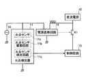
図1は、本発明の実施の形態に係る燃焼制御装置の構成を示すブロック図である。この燃焼制御装置は、交流電源10、火炎検出器11、直流電源12、制御回路13、電源遮断回路14及びリレーK1から構成されている。 FIG. 1 is a block diagram showing a configuration of a combustion control apparatus according to an embodiment of the present invention. This combustion control device includes an
交流電源10は、図示しない電源スイッチが投入されることにより、交流電力を火炎検出器11の後述する火炎センサ11a、火炎センサ駆動回路11b、及び電源遮断回路14に供給する。この交流電源10は、商用の交流電源が例えばトランスなどによって絶縁されることにより得られる電源である。 The
火炎検出器11は、例えば紫外線放電管(UVチューブ)から構成された火炎センサ11aと、この火炎センサ11aに電気的に接続され、火炎センサ11aを駆動する火炎センサ駆動回路11bと、これらを制御する火炎センサ検出回路11cとから構成されている。そして、火炎センサ11aはUVチューブからなり、火炎センサ駆動回路11bはこれを駆動するものであるので、その構造上交流電源10を利用している。その一方、火炎センサ検出回路11cは信頼性向上のため直流電源を利用している。そして、交流電源10から交流電圧が印加された状態で、パイロットバーナやメインバーナの火炎によって発生された紫外線が入射されると、火炎センサ11aにおいて交流電源の略半サイクル毎に放電が行われて放電電流が流れる。この火炎センサ11aで発生された放電電流は火炎検出器11で火炎検出信号とされ、制御回路13において火炎有無の判断に利用される。 The
一方、直流電源12は、電源スイッチの投入に同期して起動される。この直流電源12は、交流電源10とは独立して動作し、例えば図示しない別系統の商用交流電源からの交流電力を整流して平滑するスイッチング電源から構成されている。なお、直流電源12は、交流電源10からの交流電力を整流して平滑するスイッチング電源から構成することもできる。この場合、スイッチング電源の変換効率は非常に高いので、瞬停や負荷の増大により交流電源10の電圧が低下しても相当期間は所定の直流電圧を出力し続けることができる。すなわち、異なる電源電圧によって作動する2つの異なる回路がそれ自体の構成、すなわち本発明の特徴部分である電源遮断回路14を有さない場合は、一方の電源電圧の低下によって他方の電源電圧によって作動する回路がこの一方の電源電圧の低下と同期して機能不全に陥ることはない。この直流電源12から出力される直流電圧は、電源遮断回路14に供給されるとともに、リレーK1の接点を経由して制御回路13に供給される。 On the other hand, the
制御回路13は、直流電源12からリレーK1を経由して供給される直流電力により動作する。この制御回路13は、例えばスタートチェックを行うためのスタートチェック回路、パイロットバーナやメインバーナの点火を制御するための点火回路、アラームを出力するためのアラーム回路など(何れも図示は省略する)を含むリレーの駆動やシーケンスの制御、スタートチェック用の制御回路である。この制御回路13は、例えばスタートチェック回路において、火炎検出器11からの火炎検出信号に基づき異常の有無をチェックし、このチェックの結果、異常が無いことを判断した場合は、燃焼装置を起動し、もし何らかの異常が有ることを判断した場合は安全スイッチを作動させて当該燃焼制御装置をロックアウトし、燃焼装置の起動を阻止する。 The
電源遮断回路14は、瞬停や負荷の増大による交流電源10の出力電圧の低下を検出し、直流電源12からの直流電圧VDDによってリレーK1のコイル(図1中には図示せず)を駆動し、その接点を開放させる。これにより、直流電源12から制御回路13への直流電力の供給が停止される。 The power cut-
すなわち、この電源遮断回路14は、異なる電源電圧によって電力が供給される2つの異なる回路を有する場合に、一方の電源電圧の低下によって他方の電源電圧によって作動する回路を一方の電源電圧の低下と同期して積極的に機能不全に陥らせる役目を果たしている。これによって、燃焼装置を点火する前に実施される自己点検において異常が発生した場合、交流電源の瞬停による電圧低下が起きてもこの異常発生を正常状態と誤判断することなく燃焼装置の起動を確実に抑止して異常状態にも係わらず正常状態時の燃焼シーケンスに移行するのを確実に阻止するようになっている。 That is, when the power cut-
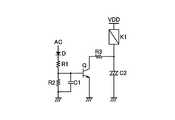
図2は、電源遮断回路14の具体的な構成例を示す回路図である。この電源遮断回路14は、ダイオードD、抵抗R1〜R3、コンデンサC1及びC2、トランジスタQ並びにリレーK1のコイルから構成されている。 FIG. 2 is a circuit diagram showing a specific configuration example of the power shut-
ダイオードDのアノードは交流電源10に接続されており、この交流電源10から交流電圧ACが印加される。ダイオードDのカソードは抵抗R1の一端に接続されている。抵抗R1の他端は、抵抗R2の一端、コンデンサC1の一端及びトランジスタQのベースに接続されている。抵抗R2の他端及びコンデンサC1の他端は接地されている。 The anode of the diode D is connected to an
トランジスタQは、例えばNPN型のバイポーラトランジスタから構成されており、そのエミッタは接地され、コレクタは抵抗R3の一端に接続されている。抵抗R3の他端は、リレーK1のコイルを介して直流電源12に接続されるとともに、コンデンサC2の一端に接続されている。コンデンサC2の他端は接地されている。 The transistor Q is composed of, for example, an NPN-type bipolar transistor, its emitter is grounded, and its collector is connected to one end of the resistor R3. The other end of the resistor R3 is connected to the
次に、上記のように構成される本発明の実施の形態に係る燃焼制御装置の動作を説明する。なお、この説明にあたっては理解の容易化のために図3に示すフローチャートに基づいて説明するが、実際にはこれらの動作は同時に行われていると理解すべきである。 Next, the operation of the combustion control apparatus according to the embodiment of the present invention configured as described above will be described. In this description, for ease of understanding, description will be made based on the flowchart shown in FIG. 3, but it should be understood that these operations are actually performed at the same time.
まず、図示しない電源スイッチが投入されると、電源の供給が開始される(ステップS1)。すなわち、交流電源10は、交流電圧ACを火炎検出器11の火炎センサ11a、火炎センサ駆動回路11b、及び電源遮断回路14に供給する。これにより、火炎検出器11は火炎の検出を開始する。また、電源遮断回路14は交流電圧ACが低下したか否かの監視を開始する。また、電源スイッチの投入に同期して起動された直流電源12は、直流電圧VDDを電源遮断回路14に供給する。 First, when a power switch (not shown) is turned on, supply of power is started (step S1). That is, the
この点についてさらに詳細に説明すると、交流電源10から交流電圧ACが印加された火炎検出器11は火炎の有無を検出し、その検出結果は火炎検出信号として制御回路13において信号処理される。また、交流電源10から交流電圧ACが印加された電源遮断回路14は以下のように動作する。すなわち、交流電源10からの交流電圧ACがダイオードDのアノードに印加されると、ダイオードDのカソード側には、正の半波の直流電圧が出力される。この半波の直流電圧は、抵抗R1と抵抗R2とによって抵抗分割されるとともにコンデンサC1で平滑化され、所定値を有する直流電圧としてトランジスタQのベースに印加される。 This point will be described in more detail. The
このベースに印加された直流電圧によりトランジスタQはオンし、直流電源12からの直流電圧VDDがリレーK1のコイルに印加される。その結果、直流電源12から、リレーK1のコイル、抵抗R3、及びトランジスタQを経由して電流が接地に流れ、リレーK1の接点が閉成される。これにより、直流電源12からリレーK1の接点を経由して、制御回路13に直流電力が供給される。 The transistor Q is turned on by the DC voltage applied to the base, and the DC voltage VDD from the
このように制御回路13に直流電力が供給された状態で、燃焼装置の点火前に実施される自己点検であるスタートチェックが行われる(ステップS2)。すなわち、制御回路13内のスタートチェック回路(図示は省略する)は、あらかじめ定められたシーケンスに従って種々の自己点検(詳細な説明は省略する)を行う。そして、このスタートチェックにおいては、そのチェック項目として、火炎検出信号が有るかどうかが調べられる(ステップS3)。具体的には、制御回路13内のスタートチェック回路は、火炎検出器11に基づいて得られた火炎検出信号が火炎有りを表しているか否かを調べる。 In this way, a start check, which is a self-check performed before ignition of the combustion device, is performed with the DC power supplied to the control circuit 13 (step S2). That is, the start check circuit (not shown) in the
このステップS3で、火炎検出信号に基づいて火炎有りと判断されると、燃焼装置の起動が停止される(ステップS4)。すなわち、制御回路13内のスタートチェック回路は、スタートチェックの段階で存在するはずのない火炎が存在するので擬似火炎とみなし、以後のシーケンスを中止して燃焼制御装置をロックアウト状態にする。これにより、リセット操作がなされるまで燃焼制御装置は動作不可能にされ、燃焼装置の安全性が確保されている。 If it is determined in this step S3 that there is a flame based on the flame detection signal, the start of the combustion device is stopped (step S4). In other words, the start check circuit in the
そして、スタート中、ステップS3で火炎検出信号有りと判断されてステップS4で起動停止とならない限り、交流電圧ACの低下の有無が調べられる(ステップS5)。具体的には、電源遮断回路14は、交流電圧ACが低下してトランジスタQのベースに印加する直流電圧が低レベルであるかどうかを判断する。 Then, during the start, unless it is determined in step S3 that there is a flame detection signal and the activation is not stopped in step S4, it is checked whether or not the AC voltage AC has decreased (step S5). Specifically, the
このステップS5で、交流電圧ACの瞬間的かつ僅かな低下があった場合にこの電圧低下が有ることが判断されると、本発明の特徴部分である燃焼制御装置の即時停止動作を行う(ステップS6)。すなわち、擬似火炎が存在するにも拘わらず交流電圧ACの低下によって擬似火炎信号が無いと判断される場合があるが、電源遮断回路14は、交流電圧ACの低下によってトランジスタQのベースに印加される電圧が低レベルとなることで、交流電源ACの低下と連動して(同期して)トランジスタQをオフし、リレーK1のコイルに流れる電流を遮断する。これにより、リレーK1の接点が開放され、直流電源12から制御回路13に対する直流電力の供給が交流電源の瞬停によるわずかな電圧低下と連動して(同期して)停止される。その結果、制御回路13内のスタートチェック回路による以後のシーケンスは中止されて当該燃焼制御装置はロックアウト状態にされ、擬似火炎が有るにもかかわらず交流電源の瞬停による擬似火炎無しとの誤判断に基づいて制御回路が続く燃焼シーケンスに移行するのを確実に防止する。これによって、リセット操作がなされるまで当該燃焼制御装置は動作不可能にされ、燃焼装置の安全性が確保される。 If it is determined in step S5 that the voltage drop is present when there is an instantaneous and slight drop in the AC voltage AC, an immediate stop operation of the combustion control device, which is a feature of the present invention, is performed (step S5). S6). That is, although there is a case where it is determined that there is no pseudo flame signal due to a decrease in the AC voltage AC in spite of the presence of the pseudo flame, the
上記ステップS3における火炎検出信号有無の判断と上記ステップS5における交流電圧ACの低下があったか否かの判断をスタートチェック中常に行い(ステップS7)、スタートチェックにおける他のチェック項目に異常が無くスタートチェックが無事に終了したならば、燃焼装置の起動が行われる(ステップS8)。これにより、燃焼装置が点火されて正常運転に入る。 The determination of the presence or absence of the flame detection signal in step S3 and the determination of whether or not the AC voltage AC has decreased in step S5 is always performed during the start check (step S7), and there is no abnormality in other check items in the start check. If the process is successfully completed, the combustion apparatus is started (step S8). As a result, the combustion device is ignited and normal operation is started.
以上説明したように、本発明の実施形態に係る燃焼装置によれば、交流電源10から出力される交流電圧ACが低下した場合は、電源遮断回路14は、この交流電圧ACの低下と同期して直流電源12から制御回路13への直流電力の供給を停止する。従って、燃焼装置を点火する前に実施される自己点検中に火炎検出器11によって擬似火炎が検出されている状態で、交流電源10から出力される交流電圧ACが瞬停や負荷の増大によって低下して擬似火炎信号が消滅しても、交流電圧ACの低下と同期して直流電源12からの直流電力は制御回路13に供給されないので、制御回路13は正常である旨の判断を行わない。その結果、燃焼装置の点火が阻止されるので、燃焼装置が誤って起動されることを防止できる。 As described above, according to the combustion apparatus according to the embodiment of the present invention, when the AC voltage AC output from the
すなわち、本発明による電源遮断回路を有することで、異なる電源電圧によって電力が供給される2つの異なる回路を有する場合に、一方の電源電圧の低下によって他方の電源電圧によって作動する回路をこれと同期して積極的に機能不全に陥らせるようにする。これによって、燃焼装置を点火する前に実施される自己点検において異常が発生した場合、電源の瞬停による電圧低下が起きてもこの異常発生を正常状態と誤判断することなく燃焼装置の起動を確実に抑止し、異常状態にも係わらず正常状態時の燃焼シーケンスに移行するのを阻止することができる。 That is, by having the power cutoff circuit according to the present invention, in the case of having two different circuits to which power is supplied by different power supply voltages, a circuit that operates with the other power supply voltage when one power supply voltage decreases is synchronized with this. To actively fall into dysfunction. As a result, if an abnormality occurs during a self-inspection conducted before the combustion device is ignited, the combustion device can be started without misjudging the occurrence of the abnormality as a normal state even if a voltage drop occurs due to a momentary power failure. It is possible to reliably suppress the transition to the combustion sequence in the normal state despite the abnormal state.
10 交流電源
11 火炎検出器
11a 火炎センサ
11b 火炎センサ駆動回路
11c 火炎センサ検出回路
12 直流電源
13 制御回路
14 電源遮断回路
K1 リレー
R1〜R3 抵抗
C1、C2 コンデンサ
D ダイオード
Q トランジスタDESCRIPTION OF
Claims (3)
Translated fromJapanese火炎センサ、火炎センサ駆動回路、及び火炎センサ検出回路からなる火炎検出器であって、当該火炎センサ及び火炎センサ駆動回路が第1の電源から出力される電力によって動作し、火炎の有無を検出して火炎検出信号として出力する火炎検出器と、
前記第1の電源とは独立して動作する第2の電源から出力される電力によって動作し、前記火炎検出器から得られた火炎検出信号に基づき疑似火炎による異常の有無を調べ、当該異常が有ることを判断した場合に前記燃焼装置の点火を阻止する制御回路と、
前記第1の電源の出力が低下した場合に、前記第2の電源から前記制御回路への電力供給を前記第1の電源の出力低下と同期して停止させる電源遮断回路、
を備えたことを特徴とする燃焼制御装置。In a combustion control device that performs self-inspection before igniting the combustion device,
A flame detector comprising a flame sensor, a flame sensor drive circuit, and a flame sensor detection circuit, wherein the flame sensor and the flame sensor drive circuit are operated by electric power output from a first power source to detect the presence or absence of a flame. A flame detector that outputs a flame detection signal,
It operates with electric power output from a second power source that operates independently of the first power source, and checks whether there is an abnormality due to a pseudo flame based on a flame detection signal obtained from the flame detector. A control circuit for preventing ignition of the combustion device when it is determined that there is,
A power cut-off circuit for stopping power supply from the second power supply to the control circuit in synchronization with the output drop of the first power supply when the output of the first power supply is lowered;
A combustion control device comprising:
前記第2の電源は、直流電力を出力する直流電源からなり、
前記電源遮断回路は、前記第1の電源から出力される交流電圧が所定値より低下した場合に、前記第2の電源から前記制御回路への直流電力の供給を停止させることを特徴とする、請求項1記載の燃焼制御装置。The first power source includes an AC power source that outputs AC power,
The second power source is a DC power source that outputs DC power,
The power cutoff circuit stops the supply of DC power from the second power source to the control circuit when the AC voltage output from the first power source drops below a predetermined value. The combustion control device according to claim 1.
前記電源遮断回路は、前記第1の電源から出力される交流電圧が所定値より低下した場合に前記電気素子に流れる電流を遮断して該電気素子を開放させることを特徴とする、請求項2記載の燃焼制御装置。The second power source supplies DC power to the control circuit via an electric element,
The power supply cutoff circuit cuts off a current flowing through the electric element and opens the electric element when an AC voltage output from the first power supply drops below a predetermined value. The combustion control device described.
Priority Applications (1)
| Application Number | Priority Date | Filing Date | Title |
|---|---|---|---|
| JP2005128655AJP4479965B2 (en) | 2005-04-26 | 2005-04-26 | Combustion control device |
Applications Claiming Priority (1)
| Application Number | Priority Date | Filing Date | Title |
|---|---|---|---|
| JP2005128655AJP4479965B2 (en) | 2005-04-26 | 2005-04-26 | Combustion control device |
Publications (2)
| Publication Number | Publication Date |
|---|---|
| JP2006308149A JP2006308149A (en) | 2006-11-09 |
| JP4479965B2true JP4479965B2 (en) | 2010-06-09 |
Family
ID=37475238
Family Applications (1)
| Application Number | Title | Priority Date | Filing Date |
|---|---|---|---|
| JP2005128655AExpired - LifetimeJP4479965B2 (en) | 2005-04-26 | 2005-04-26 | Combustion control device |
Country Status (1)
| Country | Link |
|---|---|
| JP (1) | JP4479965B2 (en) |
Families Citing this family (1)
| Publication number | Priority date | Publication date | Assignee | Title |
|---|---|---|---|---|
| CN119383800B (en)* | 2024-12-31 | 2025-04-01 | 深圳市嘉力电气技术有限公司 | Method, device, equipment and storage medium for controlling starting of UV power supply |
- 2005
- 2005-04-26JPJP2005128655Apatent/JP4479965B2/ennot_activeExpired - Lifetime
Also Published As
| Publication number | Publication date |
|---|---|
| JP2006308149A (en) | 2006-11-09 |
Similar Documents
| Publication | Publication Date | Title |
|---|---|---|
| US4303385A (en) | Direct ignition system for gas appliance with DC power source | |
| US6280180B1 (en) | Method and system for igniting a burner of a gas stove | |
| JPS6071822A (en) | Flame detector | |
| JPS5838696B2 (en) | fuel igniter | |
| US3938937A (en) | Fuel ignition control arrangement | |
| CA2775763C (en) | Monitoring of the presence of two flames in a fuel combustion device | |
| US20210199289A1 (en) | Heating apparatus comprising combustible gas burner | |
| JP4479965B2 (en) | Combustion control device | |
| US3955910A (en) | Self-checking automatic pilot fuel ignition system | |
| US3734676A (en) | Electrically energizable control system for a fuel burner | |
| US4034270A (en) | Self-inhibiting spark generating arrangement | |
| JP4597163B2 (en) | Battery-powered gas combustion equipment | |
| EP0046280B1 (en) | Burner control system | |
| KR102083216B1 (en) | Touch Input Method of Touch panel using Two Fingers | |
| JPH07117241B2 (en) | Burner combustion safety mechanism | |
| US2903052A (en) | Safety controls for gas-fired industrial burners | |
| US4128387A (en) | Ignition device | |
| JP2007178074A (en) | Hot water system | |
| GB1568325A (en) | Fuel ignition control systems | |
| JP6383310B2 (en) | Combustion control device and combustion system | |
| JP4486903B2 (en) | Combustion control device | |
| JP5401513B2 (en) | Combustion device | |
| JPS6138377B2 (en) | ||
| JP2006329474A (en) | Flame detecting device in combustor | |
| JP3120009B2 (en) | Combustion control device |
Legal Events
| Date | Code | Title | Description |
|---|---|---|---|
| A621 | Written request for application examination | Free format text:JAPANESE INTERMEDIATE CODE: A621 Effective date:20080318 | |
| A977 | Report on retrieval | Free format text:JAPANESE INTERMEDIATE CODE: A971007 Effective date:20100305 | |
| TRDD | Decision of grant or rejection written | ||
| A01 | Written decision to grant a patent or to grant a registration (utility model) | Free format text:JAPANESE INTERMEDIATE CODE: A01 Effective date:20100310 | |
| A01 | Written decision to grant a patent or to grant a registration (utility model) | Free format text:JAPANESE INTERMEDIATE CODE: A01 | |
| A61 | First payment of annual fees (during grant procedure) | Free format text:JAPANESE INTERMEDIATE CODE: A61 Effective date:20100310 | |
| FPAY | Renewal fee payment (event date is renewal date of database) | Free format text:PAYMENT UNTIL: 20130326 Year of fee payment:3 | |
| R150 | Certificate of patent or registration of utility model | Ref document number:4479965 Country of ref document:JP Free format text:JAPANESE INTERMEDIATE CODE: R150 Free format text:JAPANESE INTERMEDIATE CODE: R150 | |
| FPAY | Renewal fee payment (event date is renewal date of database) | Free format text:PAYMENT UNTIL: 20140326 Year of fee payment:4 | |
| R250 | Receipt of annual fees | Free format text:JAPANESE INTERMEDIATE CODE: R250 | |
| EXPY | Cancellation because of completion of term |