JP4473506B2 - Selectively thinned coiled sheet stent and method for making the same - Google Patents
Selectively thinned coiled sheet stent and method for making the sameDownload PDFInfo
- Publication number
- JP4473506B2 JP4473506B2JP2002537218AJP2002537218AJP4473506B2JP 4473506 B2JP4473506 B2JP 4473506B2JP 2002537218 AJP2002537218 AJP 2002537218AJP 2002537218 AJP2002537218 AJP 2002537218AJP 4473506 B2JP4473506 B2JP 4473506B2
- Authority
- JP
- Japan
- Prior art keywords
- stent
- tubular body
- thickness
- sheet
- longitudinal
- Prior art date
- Legal status (The legal status is an assumption and is not a legal conclusion. Google has not performed a legal analysis and makes no representation as to the accuracy of the status listed.)
- Expired - Lifetime
Links
- 238000000034methodMethods0.000titledescription14
- 230000009467reductionEffects0.000claimsdescription8
- 230000036760body temperatureEffects0.000claimsdescription7
- 230000007704transitionEffects0.000claimsdescription7
- 238000005452bendingMethods0.000claimsdescription4
- 239000000463materialSubstances0.000description9
- 229910001000nickel titaniumInorganic materials0.000description7
- HLXZNVUGXRDIFK-UHFFFAOYSA-Nnickel titaniumChemical compound[Ti].[Ti].[Ti].[Ti].[Ti].[Ti].[Ti].[Ti].[Ti].[Ti].[Ti].[Ni].[Ni].[Ni].[Ni].[Ni].[Ni].[Ni].[Ni].[Ni].[Ni].[Ni].[Ni].[Ni].[Ni]HLXZNVUGXRDIFK-UHFFFAOYSA-N0.000description7
- 229910045601alloyInorganic materials0.000description5
- 239000000956alloySubstances0.000description5
- 229910001566austeniteInorganic materials0.000description5
- 210000005166vasculatureAnatomy0.000description5
- 210000003484anatomyAnatomy0.000description4
- 238000002513implantationMethods0.000description4
- 208000031481Pathologic ConstrictionDiseases0.000description3
- 230000006835compressionEffects0.000description3
- 238000007906compressionMethods0.000description3
- 230000003902lesionEffects0.000description3
- 229910000734martensiteInorganic materials0.000description3
- 229910001285shape-memory alloyInorganic materials0.000description3
- 230000036262stenosisEffects0.000description3
- 208000037804stenosisDiseases0.000description3
- XLYOFNOQVPJJNP-UHFFFAOYSA-NwaterSubstancesOXLYOFNOQVPJJNP-UHFFFAOYSA-N0.000description3
- 210000004204blood vesselAnatomy0.000description2
- 210000001715carotid arteryAnatomy0.000description2
- 238000003486chemical etchingMethods0.000description2
- 210000004351coronary vesselAnatomy0.000description2
- 238000005520cutting processMethods0.000description2
- 230000004048modificationEffects0.000description2
- 238000012986modificationMethods0.000description2
- 230000008569processEffects0.000description2
- 229910000990Ni alloyInorganic materials0.000description1
- 102100027378ProthrombinHuman genes0.000description1
- 108010094028ProthrombinProteins0.000description1
- 229910001069Ti alloyInorganic materials0.000description1
- RTAQQCXQSZGOHL-UHFFFAOYSA-NTitaniumChemical compound[Ti]RTAQQCXQSZGOHL-UHFFFAOYSA-N0.000description1
- WYTGDNHDOZPMIW-RCBQFDQVSA-NalstonineNatural productsC1=CC2=C3C=CC=CC3=NC2=C2N1C[C@H]1[C@H](C)OC=C(C(=O)OC)[C@H]1C2WYTGDNHDOZPMIW-RCBQFDQVSA-N0.000description1
- 238000004873anchoringMethods0.000description1
- 230000003143atherosclerotic effectEffects0.000description1
- 230000008901benefitEffects0.000description1
- 239000000560biocompatible materialSubstances0.000description1
- 210000001627cerebral arteryAnatomy0.000description1
- 230000008859changeEffects0.000description1
- 239000000110cooling liquidSubstances0.000description1
- 229910003460diamondInorganic materials0.000description1
- 239000010432diamondSubstances0.000description1
- 201000010099diseaseDiseases0.000description1
- 208000037265diseases, disorders, signs and symptomsDiseases0.000description1
- 238000010438heat treatmentMethods0.000description1
- 238000007654immersionMethods0.000description1
- 238000003698laser cuttingMethods0.000description1
- 230000007246mechanismEffects0.000description1
- 229910052751metalInorganic materials0.000description1
- 239000002184metalSubstances0.000description1
- 230000037361pathwayEffects0.000description1
- 229920002120photoresistant polymerPolymers0.000description1
- 229920000642polymerPolymers0.000description1
- 230000002028prematureEffects0.000description1
- 238000002360preparation methodMethods0.000description1
- 229940039716prothrombinDrugs0.000description1
- 210000002254renal arteryAnatomy0.000description1
- 239000010936titaniumSubstances0.000description1
- 230000002792vascularEffects0.000description1
- 238000003466weldingMethods0.000description1
Images


Classifications
- A—HUMAN NECESSITIES
- A61—MEDICAL OR VETERINARY SCIENCE; HYGIENE
- A61F—FILTERS IMPLANTABLE INTO BLOOD VESSELS; PROSTHESES; DEVICES PROVIDING PATENCY TO, OR PREVENTING COLLAPSING OF, TUBULAR STRUCTURES OF THE BODY, e.g. STENTS; ORTHOPAEDIC, NURSING OR CONTRACEPTIVE DEVICES; FOMENTATION; TREATMENT OR PROTECTION OF EYES OR EARS; BANDAGES, DRESSINGS OR ABSORBENT PADS; FIRST-AID KITS
- A61F2/00—Filters implantable into blood vessels; Prostheses, i.e. artificial substitutes or replacements for parts of the body; Appliances for connecting them with the body; Devices providing patency to, or preventing collapsing of, tubular structures of the body, e.g. stents
- A61F2/82—Devices providing patency to, or preventing collapsing of, tubular structures of the body, e.g. stents
- A61F2/92—Stents in the form of a rolled-up sheet expanding after insertion into the vessel, e.g. with a spiral shape in cross-section
- A—HUMAN NECESSITIES
- A61—MEDICAL OR VETERINARY SCIENCE; HYGIENE
- A61F—FILTERS IMPLANTABLE INTO BLOOD VESSELS; PROSTHESES; DEVICES PROVIDING PATENCY TO, OR PREVENTING COLLAPSING OF, TUBULAR STRUCTURES OF THE BODY, e.g. STENTS; ORTHOPAEDIC, NURSING OR CONTRACEPTIVE DEVICES; FOMENTATION; TREATMENT OR PROTECTION OF EYES OR EARS; BANDAGES, DRESSINGS OR ABSORBENT PADS; FIRST-AID KITS
- A61F2/00—Filters implantable into blood vessels; Prostheses, i.e. artificial substitutes or replacements for parts of the body; Appliances for connecting them with the body; Devices providing patency to, or preventing collapsing of, tubular structures of the body, e.g. stents
- A61F2/82—Devices providing patency to, or preventing collapsing of, tubular structures of the body, e.g. stents
- A61F2/86—Stents in a form characterised by the wire-like elements; Stents in the form characterised by a net-like or mesh-like structure
- A61F2/90—Stents in a form characterised by the wire-like elements; Stents in the form characterised by a net-like or mesh-like structure characterised by a net-like or mesh-like structure
- A61F2/91—Stents in a form characterised by the wire-like elements; Stents in the form characterised by a net-like or mesh-like structure characterised by a net-like or mesh-like structure made from perforated sheets or tubes, e.g. perforated by laser cuts or etched holes
- A—HUMAN NECESSITIES
- A61—MEDICAL OR VETERINARY SCIENCE; HYGIENE
- A61F—FILTERS IMPLANTABLE INTO BLOOD VESSELS; PROSTHESES; DEVICES PROVIDING PATENCY TO, OR PREVENTING COLLAPSING OF, TUBULAR STRUCTURES OF THE BODY, e.g. STENTS; ORTHOPAEDIC, NURSING OR CONTRACEPTIVE DEVICES; FOMENTATION; TREATMENT OR PROTECTION OF EYES OR EARS; BANDAGES, DRESSINGS OR ABSORBENT PADS; FIRST-AID KITS
- A61F2220/00—Fixations or connections for prostheses classified in groups A61F2/00 - A61F2/26 or A61F2/82 or A61F9/00 or A61F11/00 or subgroups thereof
- A61F2220/0008—Fixation appliances for connecting prostheses to the body
- A61F2220/0016—Fixation appliances for connecting prostheses to the body with sharp anchoring protrusions, e.g. barbs, pins, spikes
- A—HUMAN NECESSITIES
- A61—MEDICAL OR VETERINARY SCIENCE; HYGIENE
- A61F—FILTERS IMPLANTABLE INTO BLOOD VESSELS; PROSTHESES; DEVICES PROVIDING PATENCY TO, OR PREVENTING COLLAPSING OF, TUBULAR STRUCTURES OF THE BODY, e.g. STENTS; ORTHOPAEDIC, NURSING OR CONTRACEPTIVE DEVICES; FOMENTATION; TREATMENT OR PROTECTION OF EYES OR EARS; BANDAGES, DRESSINGS OR ABSORBENT PADS; FIRST-AID KITS
- A61F2230/00—Geometry of prostheses classified in groups A61F2/00 - A61F2/26 or A61F2/82 or A61F9/00 or A61F11/00 or subgroups thereof
- A61F2230/0002—Two-dimensional shapes, e.g. cross-sections
- A61F2230/0028—Shapes in the form of latin or greek characters
- A61F2230/0054—V-shaped
- A—HUMAN NECESSITIES
- A61—MEDICAL OR VETERINARY SCIENCE; HYGIENE
- A61F—FILTERS IMPLANTABLE INTO BLOOD VESSELS; PROSTHESES; DEVICES PROVIDING PATENCY TO, OR PREVENTING COLLAPSING OF, TUBULAR STRUCTURES OF THE BODY, e.g. STENTS; ORTHOPAEDIC, NURSING OR CONTRACEPTIVE DEVICES; FOMENTATION; TREATMENT OR PROTECTION OF EYES OR EARS; BANDAGES, DRESSINGS OR ABSORBENT PADS; FIRST-AID KITS
- A61F2250/00—Special features of prostheses classified in groups A61F2/00 - A61F2/26 or A61F2/82 or A61F9/00 or A61F11/00 or subgroups thereof
- A61F2250/0014—Special features of prostheses classified in groups A61F2/00 - A61F2/26 or A61F2/82 or A61F9/00 or A61F11/00 or subgroups thereof having different values of a given property or geometrical feature, e.g. mechanical property or material property, at different locations within the same prosthesis
- A61F2250/0036—Special features of prostheses classified in groups A61F2/00 - A61F2/26 or A61F2/82 or A61F9/00 or A61F11/00 or subgroups thereof having different values of a given property or geometrical feature, e.g. mechanical property or material property, at different locations within the same prosthesis differing in thickness
- Y—GENERAL TAGGING OF NEW TECHNOLOGICAL DEVELOPMENTS; GENERAL TAGGING OF CROSS-SECTIONAL TECHNOLOGIES SPANNING OVER SEVERAL SECTIONS OF THE IPC; TECHNICAL SUBJECTS COVERED BY FORMER USPC CROSS-REFERENCE ART COLLECTIONS [XRACs] AND DIGESTS
- Y10—TECHNICAL SUBJECTS COVERED BY FORMER USPC
- Y10S—TECHNICAL SUBJECTS COVERED BY FORMER USPC CROSS-REFERENCE ART COLLECTIONS [XRACs] AND DIGESTS
- Y10S623/00—Prosthesis, i.e. artificial body members, parts thereof, or aids and accessories therefor
- Y10S623/901—Method of manufacturing prosthetic device
Landscapes
- Health & Medical Sciences (AREA)
- Engineering & Computer Science (AREA)
- Biomedical Technology (AREA)
- Cardiology (AREA)
- Oral & Maxillofacial Surgery (AREA)
- Transplantation (AREA)
- Heart & Thoracic Surgery (AREA)
- Vascular Medicine (AREA)
- Life Sciences & Earth Sciences (AREA)
- Animal Behavior & Ethology (AREA)
- General Health & Medical Sciences (AREA)
- Public Health (AREA)
- Veterinary Medicine (AREA)
- Media Introduction/Drainage Providing Device (AREA)
- Prostheses (AREA)
- Materials For Medical Uses (AREA)
- Absorbent Articles And Supports Therefor (AREA)
Abstract
Description
Translated fromJapanese【0001】
(発明の分野)
本発明は、一般に、体腔内での移植のためのプロテーゼに関し、そしてより特定すると、選択的に薄くなった領域を備えるコイル状のシートステント、およびこのようなステントを作製するための方法に関する。
【0002】
(背景)
管状プロテーゼすなわち「ステント」は、しばしば、1つ以上の狭窄を伴い得るアテローム性動脈硬化症疾患を処置するために、血管内(例えば、冠状動脈内または頚動脈内)に移植される。ステントは、一般に、患者の脈管構造への導入を容易にするための、半径方向に収縮した状態、および処置位置において脈管壁に係合するための、拡大した状態を呈し得る、管状形状を有する。その収縮した状態において、ステントは、送達デバイス(例えば、カテーテル)の上または内部に配置され得、患者の脈管構造に経皮的に導入され得、そして標的処置位置(例えば、狭窄、閉塞、または血管内の他の病巣)に進められ得る。一旦、処置位置にくると、ステントは展開され得、そしてその拡大状態に拡張され得、これによって、脈管の壁に係合して、その後、ステントを適所に固定する。
【0003】
可塑的に変形可能な管状ステントが提唱されており、これらは最初は、その収縮した状態で提供され、そして送達カテーテル上のバルーンを覆って配置される。処置位置において、このバルーンが膨張されて、このステントの拡大した状態までこのステントが拡張されるまで、このステントを可塑的に変形させる。従って、このステントは、特定された範囲内で任意の大きさまで拡張されて、このステントが脈管の壁に実質的に係合することを確実にし得る。
【0004】
自己拡張型管状ステントもまた提唱されており、これらは、その拡大された状態を呈するよう付勢されているが、収縮した状態まで半径方向に圧縮され得る。このステントは、送達デバイスに取り付けられ得、そして送達の間は、例えば、上に重なるシースによって、収縮した状態に制限される。処置位置において、このステントは、例えば、上に重なるシースを引き込むことによって解放され得、このステントは、その拡大した状態まで自動的に拡張して、脈管壁と係合する。
【0005】
管状ステントに加えて、コイル状シートステントが提唱されている。平坦なシートが、重なる内側および外側の長手方向セクションを有する螺旋形状に巻かれ、これは、収縮した状態を規定する。コイル巻きされたシートは、少なくとも部分的に巻かれていない状態に付勢されて、拡大した状態を呈し得、そして/またはバルーンを使用して巻きを解かれて、半径方向に拡大し得る。コイル状シートステントは、格子状構造体、および内側長手方向セクションに沿った複数のフィンガーまたは歯(格子の開口部に係合するためのもの)を有し得る。一旦、コイル状シートステントが処置位置において拡張されると、内側長手方向セクションのフィンガーは、格子の対応する開口部に係合して、このステントを拡大した状態にロックし得る。
【0006】
コイル状シートステントは、血管内で増強された固定を提供し得る。なぜなら、完全に拡張したステントの大きさが、より正確に制御され得るからである。しかし、従来の矩形格子(例えば、Sigwartに対して発行された米国特許第5,443,500号に開示されるような)は、その長手方向軸を横切って、所望されるより剛性である(すなわち、蛇行した解剖学的構造を通して送達される場合に特に、所望のようには容易には屈曲し得ない)コイル状シートステントを生じ得る。
【0007】
従って、増強された可撓性を提供するステントが有用であるとみなされることが考えられる。
【0008】
(発明の要旨)
本発明は、体腔内に移植するためのプロテーゼに関し、そしてより特定すると、ステントの可撓性を増強するために選択的に薄くなった領域を備えるステント、およびこのようなステントを作製するための方法に関する。
【0009】
本発明の1つの局面によれば、ほぼ管状の本体を備えるステントが提供され、この管状の本体は、長手方向軸および周囲を有し、そして体腔への導入のために構成された大きさを有する。複数の円筒形バンドが、この管状本体に形成されており、各バンドは、ほぼジグザグのパターンを備える。このほぼジグザグのパターンは、一連の連続的な対角要素を備え得、これらの対角要素は、互いに接続されて、周囲の周りで延び、この対角要素は、好ましくは、ほぼ弓型の形状を有する。各バンドにおける全ての対角要素は、好ましくは、周囲の周りで時計回りまたは反時計回りのいずれかの方向で配向して、このステントの充填を容易にする。
【0010】
隣接する円筒形バンド間に延び、そして隣接する円筒形バンドを接続する、複数の長手方向コネクタが、提供され、これらの長手方向コネクタは、半径方向にt1の厚みを有する、厚み減少領域を有し、この厚みt1は、隣接する円筒形バンドの厚みt0より実質的に小さい。好ましい形態において、厚み減少領域の厚みt1は、円筒形バンドの厚みt0の約3分の2以下であり、そしてより好ましくは、2分の1以下である。
【0011】
好ましい実施形態において、この管状本体は、コイル状のシートであるが、本発明の原理は、実質的に閉じた管状ステントに対して等しく良好に適用され得る。この管状本体は、一般に、体腔への導入を容易にするための収縮した状態と、体腔の壁の係合のための拡大した状態との間で、拡張可能である。好ましくは、この管状本体は、拡大した状態の方へと付勢されており、そして温度活性化形状記憶特性を示し得る。ほぼジグザグのパターンが、非伸長状態と伸長状態との間で拡張可能であり得、このジグザグのパターンは、遷移温度(これは実質的に、体温より低い)より高温で伸長状態の方へと付勢される。
【0012】
本発明の別の局面によれば、ほぼ管状の本体を備えるステントが提供され、この管状の本体は、長手方向軸、周囲、および厚みt0を有し、そして体腔への導入のために構成された大きさを有する。複数のセルが、管状本体に形成され、複数のコネクタが、隣接するセル間に延び、そして隣接するセルを接続し、そして複数のスロットが管状本体に形成され、そして管状本体の周囲の周りで、長手方向軸に対して実質的に垂直に配向しており、そしてこれらのスロットは、厚みt1を規定し、この厚みt1は、管状本体の厚みt0より実質的に小さい。
【0013】
本発明のなお別の局面によれば、ステントを作製するための方法が提供され、この方法は、長さ、幅、および厚みt0を有する平坦なシートを提供する工程を包含する。複数の開口部が、このシートに形成されて、複数セル構造を規定する。複数のスロットが、例えば、鋸でシートに切込みを入れることによって、シートに形成され、これらのスロットは、このシートの長さに対して実質的に垂直に整列し、これらのスロットは、このシートの厚みt0より小さな、減少した厚みt1を有する。好ましくは、このシートは、形状記憶合金から形成され、そして複数のスロットは、この形状記憶合金の機械的特性を実質的に変化させることなく、このシートに形成される。このシートは、その長さの周囲に管状本体に巻かれ、この管状本体は、体腔への導入のために構成された直径を有する。
【0014】
好ましい方法において、複数の開口部をシートに形成する工程は、複数のセルおよび長手方向コネクタを、このシートに形成する工程を包含する。長手方向に隣接するセルは、好ましくは、長手方向コネクタによって互いに接続されており、このコネクタは、シートの長さに対して実質的に垂直に、セットとして整列される。複数のスロットは、好ましくは、スロットが長手方向コネクタの各セットと交差するように形成され、これによって、長手方向コネクタの各々における厚み減少領域を提供する。コネクタの厚み減少領域は、得られるステントの可撓性特性を増強し得る(例えば、蛇行する解剖学的構造を通して進められる場合に、ステントの屈曲を容易にする)。
【0015】
本発明の他の課題および特徴は、以下の説明を、添付の図面と組み合わせて考慮することによって、明らかになる。
【0016】
(好ましい実施形態の詳細な説明)
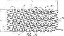
ここで図面を参照すると、図1A〜4は、本発明の1つの局面による、コイル状シートステント10の好ましい実施形態を示す。図1Aおよび1Bに最良に見られるように、コイル状シートステント10は、一般に、実質的に平坦なシート12から形成され、このシートは、長手方向軸18を間に規定する、第一および第二の端部14、16を有する。シート12はまた、第一および第二の長手方向縁部20、22を備え、第一の縁部20は、長手方向軸18に対して実質的に垂直に延びる、複数の突出部24を有する。シート12は、初期厚みt0(図3に示される)を有し、この厚みは、約0.005〜0.009インチ(0.15〜0.25mm)の間であり、そして好ましくは、約0.0065〜0.0075インチ(0.16〜0.19mm)の間の範囲であり得る。
【0017】
さらに、シート12は、図1Aに示すように、長さLおよび幅Wを有する。長さLは、このステントが処置位置において病巣を実質的に覆うため、および/または病巣のいずれかの側の健常な組織に係合するために十分な長さであることを確実にするように、選択され得る。例えば、長さLは、ステント装着される特定の解剖学的構造に依存して、約0.75〜2.0インチ(20〜50mm)の間の範囲であり得る。幅Wは、その拡大した状態において所望の直径(すなわち、処置される血管の壁または他の体腔に実質的に係合するため)を有するコイル状シートステントを提供するように、選択され得る。幅Wは、好ましくは、ステントがその拡大した直径(例えば、約0.075〜0.60インチ(1.5〜15mm)の間)を呈する場合に、コイル状シートの内側セクションおよび外側セクションが、以下にさらに記載されるように、少なくとも部分的に重なり続けるように、選択される。ステントのメッシュが、送達システムに格納される場合に幅の寸法が圧縮されるように、設計されるので、その代表的な直径を狙うために必要とされるステントの圧縮幅Wは、このメッシュを用いて達成され得る圧縮の程度に依存し得る。代表的に、このメッシュは、幅の寸法が100%と300%との間で首尾よく圧縮されるように、設計され得る。例えば、拡張したステント状態において、幅Wは、約1.0〜1.5インチ(25〜40mm)の間の範囲であり得る。
【0018】
図1Aおよび1Bに戻ると、シート12は、実質的に対角の要素32および長手方向コネクタ34から形成された複数のセル30を備え、これによって、複数セルのメッシュ構造を規定する。セル30は、好ましくは、格子様の構造を規定し、そして以下にさらに説明されるように、突出部24を受容するための複数の開口部を提供する、列および行で配置される。好ましくは、各列におけるセル30は、互いに直接的に接続され、一方で隣接する列におけるセル30は、これらの間に延び、そしてこれらを接続する、長手方向コネクタ34を有する。
【0019】
シート12の複数セルメッシュ構造において、隣接する実質的に対角の要素32の終点は、互いに接続されて、ほぼジグザグのパターンを提供し、これは、長手方向軸18に対して実質的に垂直に延びる。実質的に対角の要素32は、好ましくは、これらの終点の周囲で旋回可能であり、これによって、セル30が、長手方向軸18に対して実質的に垂直な方向に、拡張および/または収縮することを可能にする。従って、セル30は、図1Aに示される、圧縮された、すなわち「未伸長」状態、および図1Bに示される、拡張した、すなわち「伸長」状態を呈し得る。
【0020】
長手方向コネクタ34は、隣接する実質的に対角の要素32の終点が互いに接続する位置で、隣接する対のジグザグのパターンの間に延び、そしてこれらを接続する。好ましくは、隣接するセル30は、互いに位相がずれており(例えば、90°)、その結果、コネクタ34は、互いに最も近い隣接するセル30の終点間に延びる。これは、ステント10がその拡張した直径を呈する場合の長手方向圧縮力に供されるコネクタ34を最小にし得る(そうでなければ、コネクタ34の座屈を引き起こし得る)。
【0021】
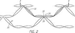
本発明によってステントに提供されるセルは、多数の異なる形態をとり得る。例えば、1998年11月16日に出願された出願番号09/192,977(その開示は明白に本明細書中に参考として援用される)は、このような多数の配置を開示する。特に図2を参照すると、このような複数セルのメッシュ構造の好ましい実施形態は、弓型の形状を有する実質的に対角の要素32を備える、複数のセル30を備えることが示される。各列または円筒形バンドにおいて、全ての弓型形状の対角要素32は、好ましくは、同じ方向に配向する。すなわち、周囲の周りで「時計回り」または「反時計回り」のいずれかの方向である。この特徴は、対各要素32の互いとの「充填」を容易にし得る(すなわち、対角要素の重なりを引き起こすことなく、コイル状シートステント10をその未伸長状態に圧縮するため)。より特定すると、ステント10の全てのセルにおける対角要素32の全てが、好ましくは、図4に見られるように、時計回りに配向する。従って、下にある対角要素32の正確な位置は、上にある対角要素32から離れて配向し得、このことは、内側セクションおよび外側セクションのスライドを容易にし、そして拡張の間に、下にある対角要素が上にある対角要素を捕捉する可能性を低下させる。
【0022】
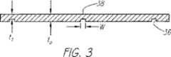
図1B、2、および3に最良に見られるように、複数のスロット36が、シート12に提供され、これらのスロット36は、好ましくは、長手方向軸18に対して実質的に垂直に配向している。スロット36は、減少した厚みt1を規定する、予め決定された深さを有し、この厚みt1は、シート12の初期の厚みt0よりかなり小さい。好ましくは、長手方向コネクタ32は、セットで整列し、各セットが、スロット36によって交差される。従って、長手方向コネクタ32の各々は、好ましくは、長手方向コネクタ32の長さに少なくとも部分的に沿って延びる、幅wを有する、厚み減少領域38を備える。
【0023】
あるいは、別個のスロットの代わりに、選択的な壁厚減少は、より広い領域に提供され得、従って、より分散されたコンプライアンスを作製し得る。また、代替の設計としては、壁厚減少の深さは、局所領域でより大きな可撓性またはより小さな可撓性を作製するように、例えば、ステントの長さに沿った異なる位置で、ステント内の異なる点で、変動し得る。例えば、いくつかの適用において、ステントの末端領域で可撓性を増加させ、ステントの中央領域で可撓性をより減少させるために提供することが望ましくあり得る。
【0024】
スロット36または厚み減少領域38は、以下にさらに記載されるように、ステント10の可撓性特性を高め得、長手方向の軸18を横切るステント10の屈曲を容易にする。対角要素またはコネクタの「厚み」寸法(すなわち、フラットシートによって規定される平面に実質的に垂直な寸法(またはシートが管状形態へと丸められる場合は、その半径方向の寸法)を変動させることによって得られる利点は、対角要素またはコネクタの「幅」(すなわち、シートによって規定される平面に実質的に平行な寸法(またはシートが管状形態へと丸められる場合は、長手方向または周囲方向の寸法)を変動させることによって提供される、任意の可撓性への追加であり得る。
【0025】
好ましい実施形態において、スロット36または厚み減少領域38での厚みt1は、シート12の初期の厚みt0の約3分の2よりも大きくなく、そして好ましくは、シート12の初期の厚みt0の約半分よりも大きくない。従って、約0.0053インチの厚みt0を有するシート12に関して、厚み減少領域38は、好ましくは、約0.0027インチ以下の厚みt1を有する。それに加えて、スロット36または厚み減少領域38の幅wは、約0.002〜0.006インチ(0.05〜0.15mm)の間であり得、そして、好ましくは、約0.003〜0.005インチ(0.075〜0.125mm)の間であり得る。スロット36は、示されるように、コネクタ34の長さに沿って部分的にのみ延び得るか、あるいは、コネクタ34の全長に実質的に対応する幅を有し得る(図示せず)。
【0026】
図4に最もよく示されるように、シート12は、好ましくは、内側長手方向セクション40および外側長手方向セクション42の重なりを規定するコイル巻きされた状態で提供され、内側長手方向セクション40および外側長手方向セクション42は、お互いに対して周囲方向に滑り得、収縮した状態と、1つ以上の拡大した状態との間を、コイル状シート10の半径方向に拡大し得る。コイル巻きされたシートステント10は、好ましくは、半径方向に拡大し得るために少なくとも部分的に広げられるように付勢している。あるいは、コイル巻きされたシートステント10は、収縮した状態まで付勢させ得るか、または可塑的に変形可能であり、それによって、ステント10をその拡大した状態まで半径方向に拡大するために、バルーンまたは他の拡張可能な部材を必要とし得る。
【0027】
コイル状のシートステントに関するさらなる情報は、例えば、米国特許第4,577,631号(Kreamerの名前で1986年3月25日発行)、同第5,007,926号(Derbyshireの名前で1991年4月16日発行)、同第5,158,548号(Lauらの名前で1992年10月28日発行)、米国再発行特許発明第34,327号(Kreamerの名前で1993年7月27日に再発行)、米国特許第5,423,885号(Williamsの名前で1995年6月13日発行)、同第5,441,515号(Khosraviらの名前で1995年8月15日発行)、同第5,443,500号(Sigwartの名前で1995年8月22日発行)、および同時係属中の出願番号09/192,977号(1998年11月16日出願)、同09/427,260号(1999年10月25日出願)、および同09/347,845号(1999年7月2日出願)中に見い出され得る。これらの参考文献の開示およびこれらの参考文献に引用される任意の他の参考文献の開示は、本明細書中で明らかに参考として援用される。
【0028】
好ましい実施形態において、ステント10は、形状記憶合金(例えば、ニッケルおよびチタンの合金(「Nitinol」))から形成され、体温または体温より低い温度で、温度によって活性化する形状記憶特性を示す。例えば、第1の温度(例えば、Nitinol合金が、そのマルテンサイト相にある温度)で、セル30は、例えば、図1Aに示されるように、周囲方向に圧縮した状態または伸展していない状態に付勢され得る。より高い第2の温度(例えば、Nitinol合金が、そのオーステナイト相へと、オーステナイト転移を受け得る遷移温度より高い温度)で、セル30は、例えば、図1Bに示されるように、周囲方向に拡大された状態または伸展した状態を呈するように付勢させれ得る。好ましくは、上記の第1の温度は、一般に、周囲温度に等しいかまたは周囲温度より低く、例えば、25℃以下であり、上記第2の温度は、一般に、周囲温度と体温の間であり、すなわち、体温または体温より低く、例えば、約37℃以下である。
【0029】
ステント10が、(例えば、第2の温度で)図1Bの拡大した状態まで付勢される場合、長手方向のコネクタ34は、好ましくは、ステント10の長手方向の軸18に実質的に軸平行に延びるように付勢される。スロット36のために、長手方向のコネクタ34は、長手方向の軸18を実質的に横切るステント10の屈曲に適応するように変形し得る。しかし、展開の際に、長手方向のコネクタ34は、以下に記載されるように、脈管の足場形成を容易にするように実質的に軸配向まで戻るように付勢される。
【0030】
本発明に従って、ステント10を操作するために、相対的に薄い、実質的に平坦なシート12が、生体適合性の材料(例えば、金属またはポリマー、好ましくは、Nitinol合金または、熱的に活性化する形状記憶特性を示し得る他の材料)から形成され、提供される。スロット36は、シート12に形成され、好ましくは、種々の公知の方法を用いてシート12から除去されることによって形成される。好ましい方法において、ウェハ鋸(図示せず)が使用され、好ましくは、その上に超低グリット研磨(super low grit abrasive)を有するブレードを有する。シート12は、水浴中に置かれ、ウェハ鋸のブレードは、水の中でシート12の幅を横切って向けられ、それによって、シート12に一連の実質的に均一な深さのスロットを作製する。水(あるいは他の冷却液体)への浸漬に起因して、シート12は、スロットの切断の間、実質的に均一な、比較的低温、好ましくは、1500Fより低い温度に維持され得る。従って、スロット36は、シート材料の機械特性を実質的に変化させることなく形成され得、このことは、得られるステント10の形状記憶の局面を維持するために特に重要であり得る。あるいは、フォトレジスト/化学エッチングプロセスが使用され得、レーザーが使用され得、またはスクライブ(例えば、ダイヤモンドチップを有する)が使用され、シート12にスロット36を形成し得る。
【0031】
次いで、セル30、突出部24、および/または複数のセル構造のための任意の他の開口部は、多くの従来のプロセス(例えば、レーザー切断、ダイおよびパンチ(die and punch)、または化学エッチング)を用いてシート12に形成され得る。あるいは、この複数のセル構造が、シート12中形成された後、シート12にスロット36が形成され得る。
【0032】
好ましい方法において、セル30は、その伸長した状態に最初は形成され(図1B)、そしてシート12は、続いて熱処理される。例えば、Nitinol合金に関して、Nitinol合金がそのオーステナイト相にある(すなわち、約500℃以上の温度で熱処理を受ける)場合、セル30の伸長した状態が、固定され、材料の形状記憶が活性化する。シート12が冷却した(すなわち、ステント材料が、そのマルテンサイト相までマルテンサイト転移を受ける)後、例えば、周囲温度以下の温度で、セル30は、その伸長していない状態まで縮む(すなわち、可塑的に変形される)(図1A)。
【0033】
次いで、シート12は、コイル状シートステント10を与えるように丸められ、ステント10は、図4に示されるように、重なり合った内側長手方向セクション40および外側長手方向セクション42を備える。好ましくは、コイル状のシートステント10は、以下にさらに記載するように、患者に導入しやすくするために「収縮された」状態に比較的きつく巻かれた状態に収縮される。代替の実施形態において、シート12は、巻かれ得、次いで、その端が、(例えば、音波溶接(sonic welding)または他の結合法を用いて)互いに接着され、閉じた管状ステントを与え得る。
【0034】
一旦ステントが、上記の収縮された状態になると、患者の体腔内への移植のための準備において、送達デバイス(図示せず)上に取り付けられ得るか、送達デバイス中に取り付けられ得る。送達デバイスは、好ましくは、患者の体腔へ(好ましくは、血管構造内へ)と経皮導入するために適応したサイズを有する。例えば、ステントは、スライド可能なバンパーを有するシース内に配置され得、このバンパーは、このシース内でステントに隣接する(図示せず)。あるいは、ステントは、ステントおよびカテーテルの上に重なる格納式のシースを備えるカテーテル上に取り付けられ得る(図示せず)。さらなる代替では、ステントを収縮した状態に制限し、そして/または送達デバイスにステントを固定するために、他の機構(例えば、早期に広げた状態になるのを防ぐために、ステントの重なり層を通って織られる、ワイヤまたは糸(図示せず))が提供され得る。
【0035】
移植の好ましい方法において、その中にステントを備えるカテーテル−シースアセンブリの遠位端は、患者の血管構造に経皮的に導入され、標的処置部位(例えば、冠状動脈、頚動脈、大脳動脈、腎臓動脈の狭窄症など)まで進められ得る。ステントが患者内で体温に到達すると、ステント材料の遷移温度を超え(例えば、Nitinol材料について、材料が、そのオーステナイト相までオーステナイト遷移を受ける)、それによって、ステントの温度で活性化する形状記憶が活性化し、その結果、セル30が、伸長した状態になるように付勢される。従って、シースが、セル30がその伸長した状態に開こうとするために、ステントが少なくとも部分的に膨張することを制限し得る。
【0036】
一旦ステントが処置部位に適切に配置されると、シースが引っ込められ、ステントが体腔内に曝され、セル30がその伸長した状態になるか、そして/またはコイル状のシートが解かれるにつれて、ステントは、半径方向に少なくとも部分的に膨張し得る。好ましくは、ステントは、自己膨張性であり、その結果、自動的に膨張し、処置部位で体腔と実質的に係合し、この身体内腔を広げる。膨張した状態において、ステント10の長手方向のコネクタ34は、好ましくは、上に説明したように、ステント10の長手方向の軸にほぼ平行に軸方向に延びるように付勢される。
【0037】
次いで、カテーテル−シースアセンブリは、引き抜かれ得る。あるいは、下に置かれたバルーンまたは他の膨張可能な部材を使用して、ステントを膨張させ得るか、またはバルーンカテーテル(図示せず)が、部分的に膨張したステントの内部へと導入され、その拡大した位置まで膨張させ得る。バルーンが膨張され、それによって、さらにステントが半径方向に膨張し得、そして一旦所望の拡大した状態が達成されると、バルーンは収縮され、引き抜かれ得る。
【0038】
拡大した状態において、内側長手方向の端20上の突出部24は、好ましくは、セル30によって規定された一連の開口部を係合し、それによって、その拡大された状態でステント10を実質的にロックする。従って、突出部24は、内側長手方向セクション40および外側長手方向セクション42が重なり、突出部24がセル30によって規定される対応する開口部を係合し得る限り、ステント10を多くの拡大した状態で止め得る。このことは、当業者によって理解される。
【0039】
代替の実施形態において、ステントは、身体経路の中でステントの係留を高めるために、外側に配向したフックまたは突起(図示せず)を備え得る。プロトロンビン材料(図示せず)は、ステントの外側表面上に提供され、身体経路の壁に対する密閉性を高め得る。
【0040】
コネクタ34の各々における厚み減少領域38は、本発明の重要な特徴である。減少された厚み領域38は、ステントの半径方向の強さを実質的に変化させ、コネクタ34がヒンジとして作用し、蛇行した解剖学的構造を通してステントの進行を容易にし得る。各コネクタおよび/または円筒形のバンドは、実質的に独立して作用し得、減少した厚み領域で屈曲して、ステントがその長手方向の軸に対して横切るように屈曲する能力を高め得る。しかし、ステント材料の弾力性のために、コネクタ34は、血管構造を通って進む間、一時的に屈曲し得るが、一旦処置位置内に置かれると、実質的にまっすぐな形状に弾性的に戻り得る。
【0041】
本発明は、種々の改変および代替形態を起こし得るが、その特定の実施例は、図面に示され、そして本明細書中で詳細に記載される。しかし、本発明は、開示される特定の形態または方法に限定されるものではなく、それとは対称的に、本発明は、添付の特許請求の範囲の精神および範囲内の、全ての改変、均質物、および変更をカバーすることが理解されるべきである。
【図面の簡単な説明】
【図1A】 図1Aは、本発明によるコイル状シートステントを形成するための、収縮した状態にある平坦なシートの側面図である。
【図1B】 図1Bは、本発明によるコイル状シートステントを形成するための、拡張状態にある平坦なシートの側面図である。
【図2】 図2は、図1Bの平坦なシートの詳細であり、その拡張状態にあるコイル状シートステントのためのセル構造の、好ましい実施形態を示す。
【図3】 図3は、図2の線3−3に沿った断面図である。
【図4】 図4は、コイル状シートステントに巻かれた、図1Aおよび1Bのシートの端面図である。[0001]
(Field of Invention)
The present invention relates generally to prostheses for implantation in body cavities, and more particularly to coiled sheet stents with selectively thinned regions and methods for making such stents.
[0002]
(background)
Tubular prostheses or “stents” are often implanted intravascularly (eg, in coronary or carotid arteries) to treat atherosclerotic disease that can involve one or more stenosis. Stents generally have a tubular shape that can exhibit a radially contracted state to facilitate introduction into the patient's vasculature and an expanded state to engage the vessel wall at the treatment location. Have In its contracted state, the stent can be placed on or in a delivery device (eg, a catheter), introduced percutaneously into the patient's vasculature, and the target treatment location (eg, stenosis, occlusion, Or other lesions in the blood vessel). Once in the treatment position, the stent can be deployed and expanded to its expanded state, thereby engaging the vessel wall and then securing the stent in place.
[0003]
Plastically deformable tubular stents have been proposed, which are initially provided in their contracted state and placed over a balloon on a delivery catheter. In the treatment position, the balloon is inflated to plastically deform the stent until it is expanded to the expanded state of the stent. Thus, the stent can be expanded to any size within the specified range to ensure that the stent substantially engages the vessel wall.
[0004]
Self-expanding tubular stents have also been proposed, which are biased to assume their expanded state, but can be radially compressed to a contracted state. The stent can be attached to a delivery device and is restricted to a contracted state during delivery, for example by an overlying sheath. In the treatment position, the stent can be released, for example, by retracting an overlying sheath, which automatically expands to its expanded state and engages the vessel wall.
[0005]
In addition to tubular stents, coiled sheet stents have been proposed. A flat sheet is wound into a spiral shape with overlapping inner and outer longitudinal sections, which defines a contracted state. The coiled sheet may be biased at least partially unrolled to assume an expanded state and / or unrolled using a balloon and expanded radially. The coiled sheet stent may have a lattice structure and a plurality of fingers or teeth (for engaging the lattice openings) along the inner longitudinal section. Once the coiled sheet stent is expanded in the treatment position, the fingers of the inner longitudinal section can engage the corresponding openings in the lattice to lock the stent in the expanded state.
[0006]
Coiled sheet stents can provide enhanced fixation within blood vessels. This is because the size of a fully expanded stent can be controlled more accurately. However, a conventional rectangular grid (eg, as disclosed in US Pat. No. 5,443,500 issued to Sigwart) is more rigid than desired across its longitudinal axis ( That is, it can result in a coiled sheet stent that cannot be bent as easily as desired, particularly when delivered through tortuous anatomy.
[0007]
Thus, it is conceivable that stents that provide enhanced flexibility are considered useful.
[0008]
(Summary of the Invention)
The present invention relates to a prosthesis for implantation in a body cavity and, more particularly, a stent with a selectively thinned region to enhance the flexibility of the stent, and for making such a stent. Regarding the method.
[0009]
In accordance with one aspect of the present invention, a stent is provided that includes a generally tubular body, the tubular body having a longitudinal axis and perimeter, and sized for introduction into a body cavity. Have. A plurality of cylindrical bands are formed in the tubular body, each band having a substantially zigzag pattern. The generally zigzag pattern may comprise a series of continuous diagonal elements that are connected to each other and extend around the periphery, the diagonal elements preferably being generally arcuate. Has a shape. All diagonal elements in each band are preferably oriented in either clockwise or counterclockwise directions around the perimeter to facilitate loading of the stent.
[0010]
A plurality of longitudinal connectors are provided that extend between adjacent cylindrical bands and connect adjacent cylindrical bands, the longitudinal connectors being t in the radial direction.1 A thickness reduction region having a thickness of1 Is the thickness t of the adjacent cylindrical band t0 More substantially smaller. In a preferred embodiment, the thickness t of the reduced thickness region1 Is the thickness t of the cylindrical band0 Less than about two-thirds, and more preferably less than one-half.
[0011]
In a preferred embodiment, the tubular body is a coiled sheet, but the principles of the present invention can be equally well applied to a substantially closed tubular stent. The tubular body is generally expandable between a contracted state for ease of introduction into a body cavity and an expanded state for engagement of a body cavity wall. Preferably, the tubular body is biased towards an expanded state and can exhibit temperature activated shape memory properties. A nearly zigzag pattern may be expandable between a non-stretched state and a stretched state, and this zigzag pattern moves toward the stretched state at higher temperatures than the transition temperature (which is substantially lower than body temperature). Be energized.
[0012]
According to another aspect of the present invention, a stent is provided comprising a generally tubular body, the tubular body having a longitudinal axis, a circumference, and a thickness t.0 And has a size configured for introduction into a body cavity. A plurality of cells are formed in the tubular body, a plurality of connectors extend between adjacent cells and connect adjacent cells, and a plurality of slots are formed in the tubular body, and around the periphery of the tubular body , Oriented substantially perpendicular to the longitudinal axis, and these slots have a thickness t1 And the thickness t1 Is the thickness t of the tubular body0 More substantially smaller.
[0013]
According to yet another aspect of the invention, a method is provided for making a stent, the method comprising length, width, and thickness t.0 Providing a flat sheet having: A plurality of openings are formed in the sheet to define a multiple cell structure. A plurality of slots are formed in the sheet by, for example, cutting a sheet with a saw, the slots aligned substantially perpendicular to the length of the sheet, and the slots are aligned with the sheet. Thickness t0 Smaller, reduced thickness t1 Have Preferably, the sheet is formed from a shape memory alloy and the plurality of slots are formed in the sheet without substantially changing the mechanical properties of the shape memory alloy. The sheet is wound around its length around a tubular body, the tubular body having a diameter configured for introduction into a body cavity.
[0014]
In a preferred method, forming the plurality of openings in the sheet includes forming a plurality of cells and longitudinal connectors in the sheet. The longitudinally adjacent cells are preferably connected to each other by a longitudinal connector, which is aligned as a set substantially perpendicular to the length of the sheet. The plurality of slots are preferably formed such that the slots intersect each set of longitudinal connectors, thereby providing a reduced thickness region in each of the longitudinal connectors. The reduced thickness region of the connector can enhance the flexibility characteristics of the resulting stent (eg, facilitate stent bending when advanced through tortuous anatomy).
[0015]
Other objects and features of the invention will become apparent from the following description considered in conjunction with the accompanying drawings.
[0016]
Detailed Description of Preferred Embodiments
Referring now to the drawings, FIGS. 1A-4 illustrate a preferred embodiment of a
[0017]
Further, the
[0018]
Returning to FIGS. 1A and 1B, the
[0019]
In the multi-cell mesh structure of the
[0020]
Longitudinal connectors 34 extend between and connect adjacent pairs of zigzag patterns where the endpoints of adjacent substantially
[0021]
The cells provided to the stent according to the present invention can take many different forms. For example, application number 09 / 192,977, filed November 16, 1998, the disclosure of which is expressly incorporated herein by reference, discloses a number of such arrangements. With particular reference to FIG. 2, a preferred embodiment of such a multi-cell mesh structure is shown comprising a plurality of
[0022]
As best seen in FIGS. 1B, 2, and 3, a plurality of
[0023]
Alternatively, instead of a separate slot, selective wall thickness reduction can be provided over a larger area, thus creating a more distributed compliance. Also, as an alternative design, the depth of wall thickness reduction may be increased at different locations along the length of the stent, for example, to create greater flexibility or less flexibility in the local region. It can vary at different points. For example, in some applications it may be desirable to provide increased flexibility at the distal region of the stent and more flexibility at the central region of the stent.
[0024]
The
[0025]
In the preferred embodiment, the thickness t at the
[0026]
As best shown in FIG. 4, the
[0027]
Further information on coiled sheet stents can be found, for example, in US Pat. No. 4,577,631 (issued March 25, 1986 in the name of Kreamer) and 5,007,926 (in the name of Derbyshire, 1991). Issued on Apr. 16), No. 5,158,548 (issued October 28, 1992 in the name of Lau et al.), US Reissue Patent No. 34,327 (issued in the name of Kreamer, July 27, 1993) U.S. Pat. No. 5,423,885 (issued under Williams name on June 13, 1995), US Pat. No. 5,441,515 (issued under the name of Khoslavi et al. On August 15, 1995) ), No. 5,443,500 (issued August 22, 1995 in the name of Sigwart), and co-pending application number 09 / 192,97. No. (filed Nov. 16, 1998), 09 / 427,260 (filed Oct. 25, 1999), and 09 / 347,845 (filed Jul. 2, 1999). . The disclosures of these references and the disclosure of any other references cited in these references are expressly incorporated herein by reference.
[0028]
In a preferred embodiment, the
[0029]
When the
[0030]
In order to operate the
[0031]
The
[0032]
In the preferred method, the
[0033]
The
[0034]
Once the stent is in the contracted state described above, it can be mounted on or in a delivery device (not shown) in preparation for implantation into a patient's body cavity. The delivery device preferably has a size adapted for percutaneous introduction into the patient's body cavity (preferably into the vasculature). For example, the stent may be placed in a sheath having a slidable bumper that is adjacent to the stent in the sheath (not shown). Alternatively, the stent can be mounted on a catheter with a retractable sheath overlying the stent and catheter (not shown). In a further alternative, other mechanisms (e.g., through the overlapping layers of the stent to prevent premature expansion) to limit the stent to a contracted state and / or secure the stent to the delivery device. Wires or threads (not shown) can be provided.
[0035]
In a preferred method of implantation, the distal end of a catheter-sheath assembly with a stent therein is introduced percutaneously into the patient's vasculature and the target treatment site (eg, coronary artery, carotid artery, cerebral artery, renal artery). Stenosis, etc.). When the stent reaches body temperature in the patient, the transition temperature of the stent material is exceeded (eg, for Nitinol material, the material undergoes an austenite transition to its austenite phase), thereby providing a shape memory that is activated at the temperature of the stent. As a result, the
[0036]
Once the stent is properly positioned at the treatment site, as the sheath is retracted, the stent is exposed into the body cavity, the
[0037]
The catheter-sheath assembly can then be withdrawn. Alternatively, the underlying balloon or other inflatable member can be used to expand the stent, or a balloon catheter (not shown) can be introduced into the partially expanded stent, It can be expanded to its enlarged position. The balloon can be inflated, thereby further expanding the stent in the radial direction, and once the desired expanded state is achieved, the balloon can be deflated and withdrawn.
[0038]
In the expanded state, the
[0039]
In an alternative embodiment, the stent may include outwardly oriented hooks or protrusions (not shown) to enhance stent anchoring within the body pathway. Prothrombin material (not shown) may be provided on the outer surface of the stent to enhance the seal against the walls of the body passage.
[0040]
A
[0041]
While the invention is susceptible to various modifications and alternative forms, specific examples thereof are shown in the drawings and are herein described in detail. However, the invention is not limited to the specific forms or methods disclosed, but in contrast thereto, the invention is intended to cover all modifications, homogeneity, and within the spirit and scope of the appended claims. It should be understood to cover objects and changes.
[Brief description of the drawings]
FIG. 1A is a side view of a flat sheet in a deflated state to form a coiled sheet stent according to the present invention.
FIG. 1B is a side view of a flat sheet in an expanded state to form a coiled sheet stent according to the present invention.
FIG. 2 is a detail of the flat sheet of FIG. 1B showing a preferred embodiment of a cell structure for a coiled sheet stent in its expanded state.
FIG. 3 is a cross-sectional view taken along line 3-3 of FIG.
FIG. 4 is an end view of the sheet of FIGS. 1A and 1B wound on a coiled sheet stent.
Claims (5)
Translated fromJapanese長手方向の軸および周囲を有し、体腔へ導入するために構成されたサイズを有する、ほぼ管状の本体であって、該管状の本体が、体腔への導入を容易にするための収縮状態と、体腔の壁を係合するための拡大された状態との間で膨張可能である、管状の本体;
該管状の本体に形成される複数の円筒形のバンドであって、各バンドが、ほぼジグザグのパターンを有する、円筒形のバンド;
隣接する円筒形のバンドの間で延び、隣接する円筒形のバンドを連結する複数の長手方向のコネクタであって、該長手方向のコネクタが、半径方向に厚みt1を有する厚み減少領域を有し、該厚みt1は、隣接する該円筒形のバンドの厚みt0よりも実質的に小さく、該長手方向のコネクタは、該管状の本体が、膨張した状態である場合、実質的に真っ直ぐな形状を呈する、長手方向のコネクタ、
を備え、ここで、該複数の円筒形のバンドおよび該複数の長手方向のコネクタが、複数セル構造を形成し;そして隣接するセルが、互いに位相がずれており、該長手方向のコネクタは、該厚み減少領域が、該管状の本体の周囲方向に延びるスロットを規定するように、お互いに整列し、該スロットが、該スロットを含む管状の本体に実質的に永久的な変形領域を有することなく、該管状の本体の屈曲特性を向上させるように構成されている、
ステント。Less than:
A generally tubular body having a longitudinal axis and circumference and having a size configured for introduction into a body cavity, wherein the tubular body is in a contracted state to facilitate introduction into the body cavity; A tubular body that is inflatable between expanded states for engaging the body cavity wall;
A plurality of cylindrical bands formed in the tubular body, each band having a generally zigzag pattern;
A plurality of longitudinal connectors extending between adjacent cylindrical bands and connecting adjacent cylindrical bands, the longitudinal connectors having a thickness reduction region having a thickness t1 in a radial direction. and said thickness seen t1 is substantially greater than the thickness t0 of the adjacent of the cylindrical band small longitudinal direction of the connector, when the tubular body is a state in which the expanded, substantially straight Connector with a longitudinal shape,
Wherein the plurality of cylindrical bands and the plurality of longitudinal connectors form a multi-cell structure; and adjacent cells are out of phase with each other, the longitudinal connectors are The reduced thickness regions are aligned with each other so as to define a circumferentially extending slot in the tubular body, the slots having a substantially permanent deformation region in the tubular body including the slot; And is configured to improve the bending properties of the tubular body,
Stent.
Applications Claiming Priority (2)
| Application Number | Priority Date | Filing Date | Title |
|---|---|---|---|
| US09/693,334US6547818B1 (en) | 2000-10-20 | 2000-10-20 | Selectively thinned coiled-sheet stents and methods for making them |
| PCT/US2001/031795WO2002034162A2 (en) | 2000-10-20 | 2001-10-05 | Selectively thinned coiled-sheet stents and methods for making them |
Publications (3)
| Publication Number | Publication Date |
|---|---|
| JP2004512093A JP2004512093A (en) | 2004-04-22 |
| JP2004512093A5 JP2004512093A5 (en) | 2005-12-22 |
| JP4473506B2true JP4473506B2 (en) | 2010-06-02 |
Family
ID=24784230
Family Applications (1)
| Application Number | Title | Priority Date | Filing Date |
|---|---|---|---|
| JP2002537218AExpired - LifetimeJP4473506B2 (en) | 2000-10-20 | 2001-10-05 | Selectively thinned coiled sheet stent and method for making the same |
Country Status (7)
| Country | Link |
|---|---|
| US (2) | US6547818B1 (en) |
| EP (1) | EP1326555B1 (en) |
| JP (1) | JP4473506B2 (en) |
| AT (1) | ATE506911T1 (en) |
| CA (1) | CA2425966C (en) |
| DE (1) | DE60144527D1 (en) |
| WO (1) | WO2002034162A2 (en) |
Families Citing this family (41)
| Publication number | Priority date | Publication date | Assignee | Title |
|---|---|---|---|---|
| US6558415B2 (en)* | 1998-03-27 | 2003-05-06 | Intratherapeutics, Inc. | Stent |
| GB0020491D0 (en) | 2000-08-18 | 2000-10-11 | Angiomed Ag | Stent with attached element and method of making such a stent |
| US7060089B2 (en) | 2002-01-23 | 2006-06-13 | Boston Scientific Scimed, Inc. | Multi-layer stent |
| AU2003239369A1 (en) | 2002-05-06 | 2003-11-17 | Abbott Laboratories | Endoprosthesis for controlled contraction and expansion |
| US7128756B2 (en) | 2002-05-08 | 2006-10-31 | Abbott Laboratories | Endoprosthesis having foot extensions |
| US7625401B2 (en) | 2003-05-06 | 2009-12-01 | Abbott Laboratories | Endoprosthesis having foot extensions |
| US7625398B2 (en) | 2003-05-06 | 2009-12-01 | Abbott Laboratories | Endoprosthesis having foot extensions |
| US7491227B2 (en)* | 2003-06-16 | 2009-02-17 | Boston Scientific Scimed, Inc. | Coiled-sheet stent with flexible mesh design |
| US7744641B2 (en)* | 2004-07-21 | 2010-06-29 | Boston Scientific Scimed, Inc. | Expandable framework with overlapping connectors |
| US20060253148A1 (en)* | 2005-05-04 | 2006-11-09 | Leone James E | Apparatus and method of using an occluder for embolic protection |
| EP2364676B1 (en) | 2005-06-30 | 2018-12-19 | Abbott Laboratories | Endoprosthesis having foot extensions |
| US20070173924A1 (en)* | 2006-01-23 | 2007-07-26 | Daniel Gelbart | Axially-elongating stent and method of deployment |
| GB0609841D0 (en) | 2006-05-17 | 2006-06-28 | Angiomed Ag | Bend-capable tubular prosthesis |
| GB0609911D0 (en) | 2006-05-18 | 2006-06-28 | Angiomed Ag | Bend-capable stent prosthesis |
| US7651523B2 (en)* | 2006-07-24 | 2010-01-26 | Cook Incorporated | Intraluminal device with flexible regions |
| GB0616999D0 (en)* | 2006-08-29 | 2006-10-04 | Angiomed Ag | Annular mesh |
| EP2063824B1 (en)* | 2006-09-07 | 2020-10-28 | Angiomed GmbH & Co. Medizintechnik KG | Helical implant having different ends |
| US20080071346A1 (en)* | 2006-09-14 | 2008-03-20 | Boston Scientific Scimed, Inc. | Multilayer Sheet Stent |
| GB0622465D0 (en) | 2006-11-10 | 2006-12-20 | Angiomed Ag | Stent |
| GB0624419D0 (en)* | 2006-12-06 | 2007-01-17 | Angiomed Ag | Stenting ring with marker |
| US20080177376A1 (en)* | 2007-01-18 | 2008-07-24 | Medtronic Vascular, Inc. | Stent With Improved Flexibility and Method for Making Same |
| KR100847432B1 (en)* | 2007-03-14 | 2008-07-21 | 주식회사 에스앤지바이오텍 | Lumen extension stent |
| GB0706499D0 (en) | 2007-04-03 | 2007-05-09 | Angiomed Ag | Bendable stent |
| GB0717481D0 (en) | 2007-09-07 | 2007-10-17 | Angiomed Ag | Self-expansible stent with radiopaque markers |
| US8414639B2 (en)* | 2008-07-08 | 2013-04-09 | Boston Scientific Scimed, Inc. | Closed-cell flexible stent hybrid |
| US20110190870A1 (en)* | 2009-12-30 | 2011-08-04 | Boston Scientific Scimed, Inc. | Covered Stent for Vascular Closure |
| KR101157916B1 (en)* | 2010-11-26 | 2012-06-22 | 박경우 | A framework for expanding bone |
| US8888843B2 (en) | 2011-01-28 | 2014-11-18 | Middle Peak Medical, Inc. | Device, system, and method for transcatheter treatment of valve regurgitation |
| US8845717B2 (en) | 2011-01-28 | 2014-09-30 | Middle Park Medical, Inc. | Coaptation enhancement implant, system, and method |
| US20140200647A1 (en)* | 2013-01-14 | 2014-07-17 | Abbott Cardiovascular Systems Inc. | Stent with enhanced profile |
| US10166098B2 (en) | 2013-10-25 | 2019-01-01 | Middle Peak Medical, Inc. | Systems and methods for transcatheter treatment of valve regurgitation |
| EP3157469B2 (en) | 2014-06-18 | 2024-10-02 | Polares Medical Inc. | Mitral valve implants for the treatment of valvular regurgitation |
| CA2958065C (en) | 2014-06-24 | 2023-10-31 | Middle Peak Medical, Inc. | Systems and methods for anchoring an implant |
| US20160045306A1 (en)* | 2014-08-18 | 2016-02-18 | Boston Scientific Scimed, Inc. | Cut pattern transcatheter valve frame |
| DE102015115279A1 (en)* | 2015-09-10 | 2017-03-16 | Bentley Innomed Gmbh | Expandable vascular support |
| US9592121B1 (en) | 2015-11-06 | 2017-03-14 | Middle Peak Medical, Inc. | Device, system, and method for transcatheter treatment of valvular regurgitation |
| JP7159230B2 (en) | 2017-03-13 | 2022-10-24 | ポラレス・メディカル・インコーポレイテッド | Devices, systems and methods for transcatheter treatment of valvular regurgitation |
| US10478303B2 (en) | 2017-03-13 | 2019-11-19 | Polares Medical Inc. | Device, system, and method for transcatheter treatment of valvular regurgitation |
| US10653524B2 (en) | 2017-03-13 | 2020-05-19 | Polares Medical Inc. | Device, system, and method for transcatheter treatment of valvular regurgitation |
| US11464634B2 (en) | 2020-12-16 | 2022-10-11 | Polares Medical Inc. | Device, system, and method for transcatheter treatment of valvular regurgitation with secondary anchors |
| US11759321B2 (en) | 2021-06-25 | 2023-09-19 | Polares Medical Inc. | Device, system, and method for transcatheter treatment of valvular regurgitation |
Family Cites Families (26)
| Publication number | Priority date | Publication date | Assignee | Title |
|---|---|---|---|---|
| US4577631A (en) | 1984-11-16 | 1986-03-25 | Kreamer Jeffry W | Aneurysm repair apparatus and method |
| CH678393A5 (en) | 1989-01-26 | 1991-09-13 | Ulrich Prof Dr Med Sigwart | |
| US5007926A (en) | 1989-02-24 | 1991-04-16 | The Trustees Of The University Of Pennsylvania | Expandable transluminally implantable tubular prosthesis |
| US5158548A (en) | 1990-04-25 | 1992-10-27 | Advanced Cardiovascular Systems, Inc. | Method and system for stent delivery |
| CA2087132A1 (en) | 1992-01-31 | 1993-08-01 | Michael S. Williams | Stent capable of attachment within a body lumen |
| US5441515A (en) | 1993-04-23 | 1995-08-15 | Advanced Cardiovascular Systems, Inc. | Ratcheting stent |
| US5637113A (en)* | 1994-12-13 | 1997-06-10 | Advanced Cardiovascular Systems, Inc. | Polymer film for wrapping a stent structure |
| US5591197A (en) | 1995-03-14 | 1997-01-07 | Advanced Cardiovascular Systems, Inc. | Expandable stent forming projecting barbs and method for deploying |
| US5980553A (en) | 1996-12-20 | 1999-11-09 | Cordis Corporation | Axially flexible stent |
| US5843117A (en) | 1996-02-14 | 1998-12-01 | Inflow Dynamics Inc. | Implantable vascular and endoluminal stents and process of fabricating the same |
| NZ331269A (en) | 1996-04-10 | 2000-01-28 | Advanced Cardiovascular System | Expandable stent, its structural strength varying along its length |
| DE69738786D1 (en)* | 1996-05-08 | 2008-07-31 | Sorin Biomedica Cardio Srl | A stent for angioplasty |
| US5807404A (en) | 1996-09-19 | 1998-09-15 | Medinol Ltd. | Stent with variable features to optimize support and method of making such stent |
| US5824052A (en)* | 1997-03-18 | 1998-10-20 | Endotex Interventional Systems, Inc. | Coiled sheet stent having helical articulation and methods of use |
| US6425915B1 (en)* | 1997-03-18 | 2002-07-30 | Endotex Interventional Systems, Inc. | Helical mesh endoprosthesis and methods of use |
| US5836966A (en) | 1997-05-22 | 1998-11-17 | Scimed Life Systems, Inc. | Variable expansion force stent |
| US5913895A (en) | 1997-06-02 | 1999-06-22 | Isostent, Inc. | Intravascular stent with enhanced rigidity strut members |
| US5843175A (en) | 1997-06-13 | 1998-12-01 | Global Therapeutics, Inc. | Enhanced flexibility surgical stent |
| FR2764794B1 (en) | 1997-06-20 | 1999-11-12 | Nycomed Lab Sa | EXPANDED TUBULAR DEVICE WITH VARIABLE THICKNESS |
| US6042606A (en) | 1997-09-29 | 2000-03-28 | Cook Incorporated | Radially expandable non-axially contracting surgical stent |
| US6156062A (en)* | 1997-12-03 | 2000-12-05 | Ave Connaught | Helically wrapped interlocking stent |
| US5938697A (en) | 1998-03-04 | 1999-08-17 | Scimed Life Systems, Inc. | Stent having variable properties |
| US6264687B1 (en)* | 1998-04-20 | 2001-07-24 | Cordis Corporation | Multi-laminate stent having superelastic articulated sections |
| US6325820B1 (en)* | 1998-11-16 | 2001-12-04 | Endotex Interventional Systems, Inc. | Coiled-sheet stent-graft with exo-skeleton |
| US6325825B1 (en)* | 1999-04-08 | 2001-12-04 | Cordis Corporation | Stent with variable wall thickness |
| JP2003503102A (en)* | 1999-06-30 | 2003-01-28 | アドバンスド、カーディオバスキュラー、システムズ、インコーポレーテッド | Variable thickness stent and method of manufacturing the same |
- 2000
- 2000-10-20USUS09/693,334patent/US6547818B1/ennot_activeExpired - Fee Related
- 2001
- 2001-10-05CACA002425966Apatent/CA2425966C/ennot_activeExpired - Fee Related
- 2001-10-05JPJP2002537218Apatent/JP4473506B2/ennot_activeExpired - Lifetime
- 2001-10-05DEDE60144527Tpatent/DE60144527D1/ennot_activeExpired - Lifetime
- 2001-10-05EPEP01981481Apatent/EP1326555B1/ennot_activeExpired - Lifetime
- 2001-10-05ATAT01981481Tpatent/ATE506911T1/ennot_activeIP Right Cessation
- 2001-10-05WOPCT/US2001/031795patent/WO2002034162A2/enactiveApplication Filing
- 2003
- 2003-01-29USUS10/354,704patent/US7122059B2/ennot_activeExpired - Fee Related
Also Published As
| Publication number | Publication date |
|---|---|
| WO2002034162A3 (en) | 2002-08-01 |
| US7122059B2 (en) | 2006-10-17 |
| JP2004512093A (en) | 2004-04-22 |
| US6547818B1 (en) | 2003-04-15 |
| DE60144527D1 (en) | 2011-06-09 |
| CA2425966A1 (en) | 2002-05-02 |
| ATE506911T1 (en) | 2011-05-15 |
| CA2425966C (en) | 2009-12-08 |
| US20030135263A1 (en) | 2003-07-17 |
| WO2002034162A9 (en) | 2003-05-01 |
| EP1326555A2 (en) | 2003-07-16 |
| EP1326555B1 (en) | 2011-04-27 |
| WO2002034162A2 (en) | 2002-05-02 |
Similar Documents
| Publication | Publication Date | Title |
|---|---|---|
| JP4473506B2 (en) | Selectively thinned coiled sheet stent and method for making the same | |
| JP4073499B2 (en) | Spiral mesh endoprosthesis | |
| EP1225844B1 (en) | Stretchable anti-buckling coiled-sheet stent | |
| ES2211220T3 (en) | EXPANDABLE PROTESIS WITH BIOCOMPATIBLE COATING. | |
| JP4087112B2 (en) | Stent design for use in peripheral vessels | |
| US6245101B1 (en) | Intravascular hinge stent | |
| EP1554993B1 (en) | Flexible, stretchable coiled-sheet stent | |
| WO1999048440A1 (en) | Helical mesh endoprosthesis and methods of use | |
| EP0864302A2 (en) | Articulated expandable intraluminal stent | |
| US20030074051A1 (en) | Flexible stent | |
| JP2009082739A (en) | Stent with changing expansion force | |
| JP2004531347A (en) | Highly flexible and flexible stent | |
| WO1995011720A1 (en) | Impermeable expandable intravascular stent | |
| WO1998058600A1 (en) | Expandable stent with variable thickness | |
| US7491227B2 (en) | Coiled-sheet stent with flexible mesh design | |
| EP0799607A2 (en) | Intravascular stent having flattened profile | |
| KR100406255B1 (en) | Stent and its manufacturing method | |
| JP2007526803A (en) | Ribbon-shaped vascular prosthesis with stress relief joint and method of use | |
| JPH1066729A (en) | Luminal expanding indwelling implement |
Legal Events
| Date | Code | Title | Description |
|---|---|---|---|
| A521 | Request for written amendment filed | Free format text:JAPANESE INTERMEDIATE CODE: A523 Effective date:20040906 | |
| A621 | Written request for application examination | Free format text:JAPANESE INTERMEDIATE CODE: A621 Effective date:20040906 | |
| A131 | Notification of reasons for refusal | Free format text:JAPANESE INTERMEDIATE CODE: A131 Effective date:20061018 | |
| A601 | Written request for extension of time | Free format text:JAPANESE INTERMEDIATE CODE: A601 Effective date:20070115 | |
| A602 | Written permission of extension of time | Free format text:JAPANESE INTERMEDIATE CODE: A602 Effective date:20070122 | |
| A521 | Request for written amendment filed | Free format text:JAPANESE INTERMEDIATE CODE: A523 Effective date:20070417 | |
| A02 | Decision of refusal | Free format text:JAPANESE INTERMEDIATE CODE: A02 Effective date:20070626 | |
| A521 | Request for written amendment filed | Free format text:JAPANESE INTERMEDIATE CODE: A523 Effective date:20070913 | |
| A911 | Transfer to examiner for re-examination before appeal (zenchi) | Free format text:JAPANESE INTERMEDIATE CODE: A911 Effective date:20071109 | |
| A912 | Re-examination (zenchi) completed and case transferred to appeal board | Free format text:JAPANESE INTERMEDIATE CODE: A912 Effective date:20071228 | |
| A01 | Written decision to grant a patent or to grant a registration (utility model) | Free format text:JAPANESE INTERMEDIATE CODE: A01 | |
| A61 | First payment of annual fees (during grant procedure) | Free format text:JAPANESE INTERMEDIATE CODE: A61 Effective date:20100305 | |
| FPAY | Renewal fee payment (event date is renewal date of database) | Free format text:PAYMENT UNTIL: 20130312 Year of fee payment:3 | |
| R150 | Certificate of patent or registration of utility model | Free format text:JAPANESE INTERMEDIATE CODE: R150 |