JP4473303B2 - Anterior cervical plate device - Google Patents
Anterior cervical plate deviceDownload PDFInfo
- Publication number
- JP4473303B2 JP4473303B2JP2007316481AJP2007316481AJP4473303B2JP 4473303 B2JP4473303 B2JP 4473303B2JP 2007316481 AJP2007316481 AJP 2007316481AJP 2007316481 AJP2007316481 AJP 2007316481AJP 4473303 B2JP4473303 B2JP 4473303B2
- Authority
- JP
- Japan
- Prior art keywords
- plate
- opening
- dimension
- screw
- bone
- Prior art date
- Legal status (The legal status is an assumption and is not a legal conclusion. Google has not performed a legal analysis and makes no representation as to the accuracy of the status listed.)
- Expired - Lifetime
Links
- 210000000988bone and boneAnatomy0.000claimsabstractdescription100
- 238000004873anchoringMethods0.000claims10
- 230000000149penetrating effectEffects0.000claims1
- 230000000712assemblyEffects0.000abstractdescription4
- 238000000429assemblyMethods0.000abstractdescription4
- 238000000034methodMethods0.000description10
- 210000003484anatomyAnatomy0.000description7
- 238000001356surgical procedureMethods0.000description6
- 206010028980NeoplasmDiseases0.000description5
- 208000037265diseases, disorders, signs and symptomsDiseases0.000description5
- 230000004927fusionEffects0.000description5
- 210000001699lower legAnatomy0.000description5
- 238000012986modificationMethods0.000description5
- 230000004048modificationEffects0.000description5
- 230000008901benefitEffects0.000description4
- 239000000463materialSubstances0.000description4
- 230000007170pathologyEffects0.000description4
- 230000002093peripheral effectEffects0.000description4
- 208000035475disorderDiseases0.000description3
- 230000006870functionEffects0.000description3
- 210000004872soft tissueAnatomy0.000description3
- 206010052428WoundDiseases0.000description2
- 208000027418Wounds and injuryDiseases0.000description2
- 230000006378damageEffects0.000description2
- 229910003460diamondInorganic materials0.000description2
- 239000010432diamondSubstances0.000description2
- 201000010099diseaseDiseases0.000description2
- 238000002513implantationMethods0.000description2
- 230000014759maintenance of locationEffects0.000description2
- 210000005036nerveAnatomy0.000description2
- 230000035515penetrationEffects0.000description2
- 230000000087stabilizing effectEffects0.000description2
- 208000035473Communicable diseaseDiseases0.000description1
- 208000032170Congenital AbnormalitiesDiseases0.000description1
- 206010027677Fractures and dislocationsDiseases0.000description1
- 241000551546MinervaSpecies0.000description1
- 206010058907Spinal deformityDiseases0.000description1
- 238000013459approachMethods0.000description1
- 230000015572biosynthetic processEffects0.000description1
- 210000004204blood vesselAnatomy0.000description1
- 210000000133brain stemAnatomy0.000description1
- 238000005266castingMethods0.000description1
- 230000000295complement effectEffects0.000description1
- 230000001054cortical effectEffects0.000description1
- 230000006837decompressionEffects0.000description1
- 238000011161developmentMethods0.000description1
- 238000005516engineering processMethods0.000description1
- 125000001475halogen functional groupChemical group0.000description1
- 238000003780insertionMethods0.000description1
- 230000037431insertionEffects0.000description1
- 230000010354integrationEffects0.000description1
- 230000007774longtermEffects0.000description1
- 210000004705lumbosacral regionAnatomy0.000description1
- 238000003754machiningMethods0.000description1
- 230000007246mechanismEffects0.000description1
- 208000015122neurodegenerative diseaseDiseases0.000description1
- 208000024335physical diseaseDiseases0.000description1
- 230000008569processEffects0.000description1
- 238000010079rubber tappingMethods0.000description1
- 210000000278spinal cordAnatomy0.000description1
- 230000006641stabilisationEffects0.000description1
- 238000011105stabilizationMethods0.000description1
- 230000003319supportive effectEffects0.000description1
- 210000002303tibiaAnatomy0.000description1
- 210000002385vertebral arteryAnatomy0.000description1
- 239000002699waste materialSubstances0.000description1
Images


Classifications
- A—HUMAN NECESSITIES
- A61—MEDICAL OR VETERINARY SCIENCE; HYGIENE
- A61B—DIAGNOSIS; SURGERY; IDENTIFICATION
- A61B17/00—Surgical instruments, devices or methods
- A61B17/56—Surgical instruments or methods for treatment of bones or joints; Devices specially adapted therefor
- A61B17/58—Surgical instruments or methods for treatment of bones or joints; Devices specially adapted therefor for osteosynthesis, e.g. bone plates, screws or setting implements
- A61B17/68—Internal fixation devices, including fasteners and spinal fixators, even if a part thereof projects from the skin
- A61B17/80—Cortical plates, i.e. bone plates; Instruments for holding or positioning cortical plates, or for compressing bones attached to cortical plates
- A61B17/8033—Cortical plates, i.e. bone plates; Instruments for holding or positioning cortical plates, or for compressing bones attached to cortical plates having indirect contact with screw heads, or having contact with screw heads maintained with the aid of additional components, e.g. nuts, wedges or head covers
- A61B17/8042—Cortical plates, i.e. bone plates; Instruments for holding or positioning cortical plates, or for compressing bones attached to cortical plates having indirect contact with screw heads, or having contact with screw heads maintained with the aid of additional components, e.g. nuts, wedges or head covers the additional component being a cover over the screw head
- A—HUMAN NECESSITIES
- A61—MEDICAL OR VETERINARY SCIENCE; HYGIENE
- A61B—DIAGNOSIS; SURGERY; IDENTIFICATION
- A61B17/00—Surgical instruments, devices or methods
- A61B17/56—Surgical instruments or methods for treatment of bones or joints; Devices specially adapted therefor
- A61B17/58—Surgical instruments or methods for treatment of bones or joints; Devices specially adapted therefor for osteosynthesis, e.g. bone plates, screws or setting implements
- A61B17/68—Internal fixation devices, including fasteners and spinal fixators, even if a part thereof projects from the skin
- A61B17/70—Spinal positioners or stabilisers, e.g. stabilisers comprising fluid filler in an implant
- A61B17/7059—Cortical plates
- A—HUMAN NECESSITIES
- A61—MEDICAL OR VETERINARY SCIENCE; HYGIENE
- A61B—DIAGNOSIS; SURGERY; IDENTIFICATION
- A61B17/00—Surgical instruments, devices or methods
- A61B17/56—Surgical instruments or methods for treatment of bones or joints; Devices specially adapted therefor
- A61B17/58—Surgical instruments or methods for treatment of bones or joints; Devices specially adapted therefor for osteosynthesis, e.g. bone plates, screws or setting implements
- A61B17/68—Internal fixation devices, including fasteners and spinal fixators, even if a part thereof projects from the skin
- A61B17/80—Cortical plates, i.e. bone plates; Instruments for holding or positioning cortical plates, or for compressing bones attached to cortical plates
- A61B17/8033—Cortical plates, i.e. bone plates; Instruments for holding or positioning cortical plates, or for compressing bones attached to cortical plates having indirect contact with screw heads, or having contact with screw heads maintained with the aid of additional components, e.g. nuts, wedges or head covers
- A61B17/8047—Cortical plates, i.e. bone plates; Instruments for holding or positioning cortical plates, or for compressing bones attached to cortical plates having indirect contact with screw heads, or having contact with screw heads maintained with the aid of additional components, e.g. nuts, wedges or head covers wherein the additional element surrounds the screw head in the plate hole
Landscapes
- Health & Medical Sciences (AREA)
- Orthopedic Medicine & Surgery (AREA)
- Life Sciences & Earth Sciences (AREA)
- Surgery (AREA)
- Neurology (AREA)
- General Health & Medical Sciences (AREA)
- Veterinary Medicine (AREA)
- Biomedical Technology (AREA)
- Heart & Thoracic Surgery (AREA)
- Medical Informatics (AREA)
- Molecular Biology (AREA)
- Animal Behavior & Ethology (AREA)
- Nuclear Medicine, Radiotherapy & Molecular Imaging (AREA)
- Public Health (AREA)
- Engineering & Computer Science (AREA)
- Surgical Instruments (AREA)
- Prostheses (AREA)
- Coating With Molten Metal (AREA)
- Chemically Coating (AREA)
- Paper (AREA)
- Diaphragms For Electromechanical Transducers (AREA)
- Orthopedics, Nursing, And Contraception (AREA)
- Massaging Devices (AREA)
- Eye Examination Apparatus (AREA)
- Absorbent Articles And Supports Therefor (AREA)
Abstract
Description
Translated fromJapanese 本発明は、脊椎用装置、特に頚椎の固定に使用される脊椎用装置に関する。
特に、本発明は、種々の脊椎の病状の治療に使用するプレート用装置に関する。The present invention relates to a spinal device, and more particularly to a spinal device used to fix a cervical spine.
In particular, the present invention relates to a plate device for use in the treatment of various spinal conditions.
いくつかの骨の構造において、脊椎は荷重を受け、その支持能力を危険にさらす種々の病理がある。脊柱は、物理的な障害に起因する変形性疾患、腫瘍の影響を受け、もちろん、骨折、脱臼もある。 In some bone structures, the spine is loaded and there are various pathologies that jeopardize its supportive ability. The spinal column is affected by degenerative diseases and tumors caused by physical disorders, and of course there are fractures and dislocations.
脊椎外科学は、数百年にわたって、広範な器具及び広範な外科的技術を用いてこれらの病理を解決し治療することに関連する困難な問題に直面してきた。細長い剛性プレートの使用は、長年の間にわたって、下方脊椎、特に胸及び腰の脊柱の安定化及び固定において有効であった。これらの同じプレート技術は、頸部の脊椎の治療を専門とする外科医による承諾を得て広い途を発見した。 For hundreds of years, spinal surgery has faced difficult problems associated with resolving and treating these pathologies using a wide range of instruments and a wide range of surgical techniques. The use of elongated rigid plates has been effective for many years in stabilizing and fixing the lower spine, particularly the chest and lumbar spines. These same plate technologies have found a wide path with the consent of surgeons specializing in the treatment of the cervical spine.
頚椎は、治療すべき脊柱の疾患または病状に依存して前方及び後方のいずれかからも接近することができる。多数の公知の外科学的な頚椎の露出及び融合技術はハワード アン医師およびジェローム コトラ医師による「脊椎装置」と題された刊行物に説明されている。また、この刊行物は、近年、もっとも多くの場合は頚椎に対して前方からの接近に関する方法に対して開発された装置について説明している。 The cervical spine can be accessed either from the front or the back depending on the disease or condition of the spine to be treated. A number of known external cervical spine exposure and fusion techniques are described in a publication entitled “Spine Devices” by Dr. Howard Ann and Dr. Jerome Kotra. This publication also describes devices that have been developed in recent years, most often for methods related to frontal access to the cervical spine.
頚椎の融合を達成する前方からの方法は、最も一般的な方法になっている。従来、頚椎の融合に関しては、融合は、横臥になった患者を牽引するような外部の治療方法、ハロー式装置またはミネルバ鋳造の使用、または他の外部安定法に依存する代わりに、内側の器具を使用することなく行われた。しかしながら、頚椎に使用することが一般的になった細長いプレートの出現により、プレート装置がこのタイプの外科手術においてよく使用されるようになった。 The anterior method of achieving cervical fusion is the most common method. Traditionally, with respect to cervical fusion, fusion is an internal instrument instead of relying on external treatment methods such as towing a lying patient, the use of halo devices or Minerva casting, or other external stabilization methods. Made without using. However, with the advent of elongated plates that have become common for use in the cervical spine, plate devices have become commonly used in this type of surgery.
多数のプレートの設計は、一層または二層の内在的に安定したプレートが可能である。また、固定プレートは、障害、変形性、腫瘍及び感染症性の治療において、上方または下方頚椎を安定する際に有効であるということができる。さらに、これらのプレートは、すぐに安定するとともに同時に減圧を可能にする他の利点を提供する。 Multiple plate designs allow for one or two layers of inherently stable plates. It can also be said that the fixation plate is effective in stabilizing the upper or lower cervical spine in the treatment of disorders, deformities, tumors and infectious diseases. In addition, these plates offer other advantages that are immediately stable and at the same time allow decompression.
頸部のプレート装置の長年にわたる開発、特に前方よりの接近において、このような装置に種々の必要性が認識されている。例えば、プレートは、6度の自由度で各椎骨の動く部材の動きを制御することができる強い機械的な固定を提供しなければならない。また、プレートは、脊柱の3つのコラムの各々と連続した軸線方向の荷重に耐えることができなければならない。プレート装置は、プレート装置が係合する解剖学的な構造または脊椎の強度を超える材料の耐久性の限度以下に応力水準を維持しなければならない。 In the long-term development of cervical plate devices, especially in the approach from the front, various needs have been recognized for such devices. For example, the plate must provide strong mechanical fixation that can control the movement of the moving members of each vertebra with 6 degrees of freedom. The plate must also be able to withstand continuous axial loads with each of the three columns of the spine. The plate device must maintain a stress level below the endurance limit of the material beyond the anatomical structure or spine strength with which the plate device engages.
プレート装置に関する他の要求は、特に頚椎の小さい空隙において、その突出を小さくするためにプレートの厚さを薄くしなければならない。プレート材料を脊椎に接続するために使用されるネジは、時間が経過しても、ゆるみがなく、プレートから出ないようにしなければならない。好ましくは、プレートは、安定性を増大するために椎骨と接触するように設計しなければならない。 Another requirement for the plate device is that the plate thickness must be reduced to reduce its protrusion, especially in small cervical cavities. The screws used to connect the plate material to the spine must remain loose and not leave the plate over time. Preferably, the plate should be designed to contact the vertebrae to increase stability.
他方、プレートはある機械的な要求を満足しなければならないが、解剖学的な外科的な要件も満たさなければならない。例えば、頸部のプレート装置は、患者への侵入を最小限にしなければならず、また周囲の柔らかい組織への傷を低減しなければならない。刊行物「脊椎装置」、並びにこの分野の他の書類では、脊柱の手術に関連する複雑性特に頸椎の手術の厳密な拘束の下において、特に、脳幹、脊髄または椎骨の動脈に対する傷のような重大な要因について言及している。また、最適なプレート装置は、装置が設定された椎骨の各々において1つ以上のネジを配置することができることが分かった。 On the other hand, the plate must meet certain mechanical requirements, but also anatomical surgical requirements. For example, cervical plate devices must minimize patient penetration and reduce wounds to surrounding soft tissue. In the publication “Spine Device”, as well as other documents in this field, under the strict constraints of spinal column surgery, particularly cervical spine surgery, especially wounds on brainstem, spinal cord or vertebral arteries. It refers to a significant factor. It has also been found that an optimal plate device can place one or more screws in each of the vertebrae for which the device is set.
この数十年で、頸骨固定装置用の必要性及び要求のいくつかを解決することができる多数の脊柱プレート装置が開発された。しかしながら、さらに改良されたプレート装置においても、脊柱を治療する際に脊柱外科医が直面するすべての病状への汎用性のある機能を有する必要性がある。例えば、プレートに関する骨ネジの固定の異なる度合いは、他の病状に対向するある病状に関するさらなる利点を有する。 In the last few decades, a number of spinal plate devices have been developed that can solve some of the needs and requirements for tibial fixation devices. However, even more improved plate devices need to have a versatile function for all medical conditions faced by spinal surgeons in treating the spine. For example, different degrees of bone screw fixation with respect to the plate have additional advantages for certain medical conditions as opposed to other medical conditions.
さらに詳細には、剛性または半剛性のいずれかの脊柱プレートに骨ネジを支持することができることは知られている。剛性の場合において、骨ネジは、プレートに関して微小な動きまたは角度を有するどのような動きも不可能である。半剛性の固定の場合、骨ネジは、脊柱の治療過程においてプレートに対していくぶん動くことができる。脊柱の変形性の病気の治療において半剛性が好ましいことが分かった。病気の椎体を交換するために移植片を移植する場合に、多少回転ができるネジの存在は、移植片を連続して支持することを確実にする。この連続的な支持は、移植片の脊柱への融合及び組み込み速度を増大する。 More particularly, it is known that bone screws can be supported on either rigid or semi-rigid spine plates. In the rigid case, the bone screw is not capable of any movement with minor movements or angles with respect to the plate. In the case of semi-rigid fixation, the bone screw can move somewhat relative to the plate during the spinal column treatment process. It has been found that semi-rigidity is preferred in the treatment of spinal deformity. When implanting a graft to replace a diseased vertebral body, the presence of a somewhat rotatable screw ensures that the graft is supported continuously. This continuous support increases the rate of fusion and integration of the graft into the spinal column.
同様に、剛性のネジ固定は、脊柱、特に頸骨区域の腫瘍または障害の治療において好ましいことが分かる。腫瘍及び障害の状態は、このような方法でさらによく治療することができる。なぜならば、骨ネジの剛性の位置決めは、神経と血管のスペースを確保し、すぐに安定性を提供するからである。確かに、剛性の骨ネジは、ディスクのスペース及び神経のスペースの安定性及び保持が重要である、骨折または大きな腫瘍による椎骨の破壊の場合には特に有効である。他方において、半剛性の固定は、変形性の病気において好ましい。なぜならば、このタイプの固定は、動的な構造が可能であるからである。変形性の状態において、骨の移植片は、ディスクスペース及び/又は椎体自身のいずれかを維持するために広く使用される。多くの場合、移植片は、落ち着き、隣接する骨に少なくとも一部が再吸収される。半剛性の骨のネジによる固定によって提供されるような動的な構造は、この現象を補償する。 Similarly, rigid screw fixation may prove preferable in the treatment of tumors or disorders of the spinal column, particularly the tibia region. Tumors and disorder conditions can be better treated in this way. This is because the positioning of the bone screw stiffness secures nerve and blood vessel space and provides immediate stability. Indeed, rigid bone screws are particularly effective in the case of fractures or vertebral destruction due to large tumors where stability and retention of disk space and nerve space is important. On the other hand, semi-rigid fixation is preferred in deformable diseases. This is because this type of fixation can be a dynamic structure. In the deformable state, bone grafts are widely used to maintain either disk space and / or the vertebral body itself. In many cases, the graft settles and is at least partially resorbed into adjacent bone. A dynamic structure, such as that provided by fixation with a semi-rigid bone screw, compensates for this phenomenon.
現在、1つのプレートに半剛性または剛性の構造のいずれかの骨ネジを位置決めすることができるプレート装置は知られていない。いくつかのプレートは、これらのネジ固定のいずれか一方について提供されるが、一つのプレートを使用し、特定の脊柱の病状及び解剖学的構造において2つのタイプの固定法のうちいずれかを外科医が選択することができるプレートはない。 Currently, no plate device is known that can position bone screws of either semi-rigid or rigid structure on one plate. Several plates are provided for either of these screw fixations, but using one plate, the surgeon can choose one of two types of fixation methods for a particular spinal pathology and anatomy. There is no plate that can be selected.
従来の装置では解決されないまま残った問題を解決するために、本発明は細長い固定プレートを用いて脊椎の前方を固定する新しい装置を考慮する。本発明の1つの側面において、固定プレートは、多数の椎骨に係合するように骨ネジが貫通する複数のネジ穴が設けられている。好ましい実施例において、ネジ穴は、骨ネジの補完的に形成された球形ヘッドを受けるために球形部分を含む。さらにネジ穴は円筒形部分と一体的であり、プレートの底部に開口している円筒形部分を含む。 In order to solve the problems that remain unsolved by conventional devices, the present invention contemplates a new device that uses an elongated fixation plate to fix the anterior portion of the spine. In one aspect of the invention, the fixation plate is provided with a plurality of screw holes through which bone screws penetrate to engage multiple vertebrae. In a preferred embodiment, the screw hole includes a spherical portion for receiving a complementary formed spherical head of the bone screw. Further, the screw hole is integral with the cylindrical portion and includes a cylindrical portion that opens to the bottom of the plate.
本発明の前方固定プレート装置の融通性は、プレートの同じネジ穴内に支持することができる固定角度ネジ及び可変角度ネジによって達成される。ネジの各々は、ネジを椎骨にネジ込むためのネジ山が形成された軸部と、球形溝内に座する球形ヘッドとを有する。双方のネジは、ネジをプレートに固定するときネジ穴の円筒形部分内にあるように形成された球形ヘッドとネジ山が形成された軸部との間の中間部分を含む。固定角度ネジの中間部分は、好ましくは、円筒形であり、ネジ穴の円筒形部分内に緊密に嵌合する寸法の外径を有する。この方法において、固定角度ネジは、ネジ穴内で回転または回動が防止される。 The flexibility of the front fixed plate device of the present invention is achieved by fixed angle screws and variable angle screws that can be supported in the same screw holes in the plate. Each of the screws has a shank formed with a thread for screwing the screw into the vertebra and a spherical head that sits in a spherical groove. Both screws include an intermediate portion between a spherical head formed to be within the cylindrical portion of the screw hole when the screw is secured to the plate and the shank on which the thread is formed. The intermediate portion of the fixed angle screw is preferably cylindrical and has an outer diameter dimensioned to fit tightly within the cylindrical portion of the screw hole. In this manner, the fixed angle screw is prevented from rotating or pivoting within the screw hole.
可変角度骨ネジは、好ましくは円筒形の中間部分を有する。しかしながら、可変角度ネジの円筒形中間部分は、ネジ穴の円筒形部分の直径よりかなり小さい外径を有する。ネジの中間部分とネジ穴との間の直径の相対的な差によって、プレートの所定の位置に固定するときであってもネジがプレートの底面に対して所定の範囲の角度をとることができるようにする。 The variable angle bone screw preferably has a cylindrical intermediate portion. However, the cylindrical intermediate portion of the variable angle screw has an outer diameter that is significantly smaller than the diameter of the cylindrical portion of the screw hole. The relative difference in diameter between the middle portion of the screw and the screw hole allows the screw to take a predetermined range of angles with respect to the bottom surface of the plate even when fixed in place on the plate. Like that.
本発明の他の側面において、固定ネジ組立体は骨ネジをプレートに固定し、それによってネジの戻ることを防止するために設けられる。本発明の1つの実施例において、固定ネジ組立体は、プレートの溝内にあるワッシャを含む。溝は、ワッシャが骨ネジを所定の位置に保持することができるように骨ネジのヘッド上に配置されることができるようにプレートの少なくとも1つのネジ穴に重複する。さらに、固定ネジ組立体は、ワッシャ溝内に同心円的に配置される雌ネジが形成された穴内に係合するネジ山が形成された組ネジを含む。固定ワッシャ自身は、固定ネジのヘッドが固定ワッシャ内に本質的に面一になるようにそれ自身に溝を形成する。 In another aspect of the invention, a fixation screw assembly is provided to secure the bone screw to the plate and thereby prevent the screw from returning. In one embodiment of the present invention, the fixation screw assembly includes a washer located in the groove of the plate. The groove overlaps at least one screw hole in the plate so that the washer can be placed on the bone screw head so that the bone screw can be held in place. Furthermore, the fixing screw assembly includes a set screw formed with a thread that engages in a hole in which a female screw is disposed concentrically in the washer groove. The locking washer itself forms a groove in itself so that the head of the locking screw is essentially flush within the locking washer.
さらに他の実施の形態において、固定組立体は、骨ネジヘッドに面する外面に形成された切り出し部分を有する固定ワッシャを含む。この切り出し部分は、ワッシャが切り出し部分の領域のネジ穴に重複しないようにネジ穴の形状に対応することが好ましい。ワッシャは、切り出し部分がネジ穴に整列する第1の位置からワッシャの外面がネジヘッドを所定の位置に固定するようにワッシャの外面がネジ穴に重複する第2の位置にワッシャが回転することができるように組ネジによってプレートに保持される。他の側面において、ワッシャは、固定ワッシャ溝内に形成された対応する切り欠き部分にかみあうように形成された下側から突出する多数のキーを有する。切り欠き部分及びキー構成は、ワッシャをネジ穴に重複する位置に固定する。 In yet another embodiment, the fixation assembly includes a fixation washer having a cut-out portion formed on the outer surface facing the bone screw head. This cutout portion preferably corresponds to the shape of the screw hole so that the washer does not overlap with the screw hole in the region of the cutout portion. The washer may rotate from a first position where the cutout portion is aligned with the screw hole to a second position where the outer surface of the washer overlaps the screw hole so that the outer surface of the washer fixes the screw head at a predetermined position. It is held on the plate by a set screw so that it can. In another aspect, the washer has a number of keys projecting from the bottom formed to engage corresponding cutouts formed in the fixed washer groove. The notch and key arrangement secure the washer in a position overlapping the screw hole.
本発明の固定プレート組立体は、1つの固定ネジ組立体によって複数のネジを固定することができる種々のネジ穴構成を有する。1つまたは複数の椎骨を取り付けるときに医師にいくつかのネジ固定における選択を提供する他の穴の構成が提供される。例えば、4つのネジ穴の構成が示されるが、この中で4つのネジ穴が1つの固定ワッシャ及びネジ組立体の周りで90°の間隔で配置されていることは前述した。医師は、椎骨の解剖学的構造に依存して4つのネジ穴のうち1つまたは複数のネジ穴内へ、固定角度ネジまたは可変角度ネジのいずれかを挿入することができる。 The fixing plate assembly of the present invention has various screw hole configurations in which a plurality of screws can be fixed by one fixing screw assembly. Other hole configurations are provided that provide the physician with several screw fixation options when attaching one or more vertebrae. For example, a configuration of four screw holes is shown, of which four screw holes are disposed at 90 ° intervals around one fixed washer and screw assembly. The physician can insert either fixed angle or variable angle screws into one or more of the four screw holes depending on the vertebral anatomy.
本発明の目的は、1つのプレートに固定角度ネジまたは可変角度ネジを固定することができる固定プレート組立体を提供することである。他の目的は、プレートに1つまたはそれ以上の骨ネジを固定することができる固定組立体を設けることである。 An object of the present invention is to provide a fixed plate assembly capable of fixing a fixed angle screw or a variable angle screw to one plate. Another object is to provide a fixation assembly that can fix one or more bone screws to the plate.
本発明によって達成される1つの利点は、固定プレート及び固定組立体が脊椎内で小さい輪郭を維持することである。他の利点は、1つの固定プレート内でいかなる固定水準においても固定角度ネジまたは可変角度ネジのいずれかを選択する能力によって達成される。 One advantage achieved by the present invention is that the fixation plate and fixation assembly maintain a small profile in the spine. Another advantage is achieved by the ability to select either fixed angle screws or variable angle screws at any fixed level within one fixed plate.
本発明の他の目的は、本発明の次の記載を添付図面を参照しながら考慮することによって明らかになる。 Other objects of the invention will become apparent upon consideration of the following description of the invention with reference to the accompanying drawings.
本発明の原理を理解することを目的として、図面に示す実施例を参照して特定の言語を使用する。そうでなければ、本発明を制限するを意図していないことを理解すべきである。明細書において記述される装置の如何なる変形および更なる改良および本発明の原理の更なる適用も、本発明に関連する技術分野の当業者には通常思いつくと考えられる。 For the purpose of understanding the principles of the invention, a specific language will be used with reference to the embodiments illustrated in the drawings. Otherwise, it should be understood that it is not intended to limit the invention. Any variations and further modifications of the apparatus described in the specification and further application of the principles of the present invention will normally occur to those skilled in the art to which the present invention pertains.
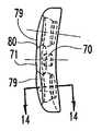
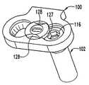
前方プレート装置または固定プレート組立体30が図1ないし図2に示されている。本発明によれば、プレート装置は、細長いプレート31と多数の骨ネジ32とを含む。骨ネジは、複数の固定ネジ組立体33によってプレート31に保持される。細長いプレート31は、種々の構成のネジ穴34を備えている。また、プレートは、プレートの側面が曲がりくねった外観を与えるように椎骨の水準のこぶ部35に分割される。特に、プレート31は、プレートの外形及び寸法を低減するためにこぶ部35の各々の間に溝を有する。さらに、こぶ部35の各々の間の減少した幅の部分は、脊椎の解剖学的構造によって要求されるようなプレートをさらに曲げることができるように材料が減少した領域を提供する。A front plate apparatus or fixed
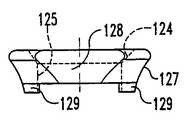
プレート31は、脊椎を取り巻く柔らかい組織に接触する丸い上方縁部36を含む。丸い縁部36は、周囲の柔らかい組織が受ける障害の大きさを小さくする。プレート31の底面37は、脊椎の水準の各々で椎体に接触し係合するような形状が好ましい。いくつかの実施例において、底面は、椎体の保持性を向上するように織り目模様を付けることができる。
図3(a)ないし図3(g)を参照すると、細長いプレート31の種々の変形例が示されている。また、本発明による前方プレート装置は、もちろん、プレートの長さ及びネジ穴の数、及び構成に依存していくつかの椎骨を容易に固定することができる。図1,2及び3(a)に示すプレートは、脊椎の5つの椎骨に係合することができるように5つの椎骨水準のこぶ部35aを含む。例えば、図3(a)のプレート31aは、椎骨C1−C5を固定するように使用することができる。図3(b) に示す細長いプレート31bは、器具が設置された椎骨の水準に依存して3つまたは4つの椎骨にわたるような寸法及び形状である。この場合、プレート31bは、4つの椎骨の水準のこぶ部35bを含み、2つのこぶ部は、プレートの両側にあり、2つのこぶ部は、プレートの中間部分に互いに片寄っている。3 (a) to 3 (g), various modifications of the
プレート31bの変形例が図3(c)に示されている。この場合、プレート31cは、3つのこぶ部35cを有し、プレートの中間部分の両側のこぶ部は、同じ椎骨水準で直接整列している。図3(d)ないし図3(e)のプレート、すなわち、プレート31d及び31eは、プレート31cと同様であるが、それらの長さは、斬新的に短い。図3(f)ないし図3(g)において最後の2つのプレート31f及び31gは、各々が2つのこぶ部35f及び35gを有する2つの椎骨水準の設定を行う。A modification of the
本発明によれば、細長いプレート31a ないし31gは、椎骨水準のこぶ部35a−35gの各々の、様々な穴のパターンを提供する。これらの穴のパターンは、少なくとも2つの骨のネジが各椎骨に係合することができるようにする。上述したように、各椎体に2つまたはそれ以上のネジを配置することが構造の安定性を改良することが分かった。本発明の目的は、各椎体に複数のネジの配置を行うだけでなく、骨ネジのゆるみまたは戻りを防止するために細長いプレートにネジを固定する手段を提供することである。その結果、本発明の他の側面においては、これらの目的を解決する種々の穴のパターンが提供される。1つのパターンは図1のプレート31の端部及び図3(a)のプレート31aの示す端部穴パターン38である。この構成において、2つのネジ穴34は、1つのこぶ部35aの横方向に配置されている。1つの固定ネジ組立体33は、2つのネジ穴34の間に配置され、各穴内に配置された骨ネジを固定するように形成されている。同様の構成が2つのネジ穴が1つの椎骨水準に配置される中間穴パターン39によって提供される。固定ネジ組立体33が2つのネジ穴34の間に配置され、端部穴パターン38にネジを固定する方法と同じ方法で各穴内に骨ネジを固定するような構成である。In accordance with the present invention, the
本発明は、4つの穴のパターンを支持するプレートを考慮している。図1、図3(a)及び図3(b)に示すこの4つの穴パターン40はダイヤモンド形状の4つのネジ穴34を提供する。1つの固定ネジ組立体33は、各穴内の骨ネジが1つの固定ネジ組立体33によって同時に固定されるようにネジ穴全体の間の中央に配置されている。図3(a)の5つのこぶ部のプレート31aにおいて、このような4つの穴のパターン40が設けられる。図3(d)の3つのこぶ部のプレート31dにおいて、4つの穴パターン40が1つだけ必要になる。4つの穴のパターン40は、いくつの骨ネジ32を1つの椎骨に係合させるか、及びどのような配置にするかを決定する際に医師にある程度の柔軟性を与えると考慮することができる。例えば、図1に示すように、椎骨水準こぶ部35で横方向に反対側に2つの骨ネジを配置することができる。別の例として、骨ネジは、プレート31aの長さに沿った向きの長手方向に反対方向のネジ穴内に配置することができる。従来の構成として骨ネジをネジ穴34にすぐに隣接するように配置する方法は少なく、または4つの穴のパターン40の穴の内3つの穴に3つの骨ネジを配置することは少ない。骨ネジ及びそれらの構成の選択が医師の裁量として残され、これは必要となる修正または固定のタイプと、特定の椎骨の解剖学的な形状に基づく。The present invention contemplates a plate that supports a pattern of four holes. The four
図3(b)及び図3(c)に示した4つの穴のクラスタ41によってネジ穴34の他の構成が提供される。プレート31bの4つの穴のクラスタ41において、2つの穴の対41a及び41bが設けられている。穴の対の各々は、2つのネジを各穴の対のネジ穴に固定するためにそれ自身の固定ネジ組立体33を含む。図3(b)に示すように、特定の穴の対の向きは、1つの椎骨で互いに関して横方向に各対から1つのネジ穴を提供する。各対のネジ穴の他方は、中央ネジ穴から長手方向に片寄っており、プレート31bの端部にさらに接近するように配置される。この方法において、2つの穴の対の各々の2つの中央穴は、1つの椎骨に係合し、穴の対41a及び41bの残りのネジ穴は、隣接する上下の椎骨に配置することができる。しかしながら、4つの穴のクラスタ41のネジ穴の各々は、1つの椎骨の上方あるいは該椎骨からわずかに片寄った方向を向いているのが最も好ましい。医師は、椎骨上に最適に整列した2つの穴の対のネジ穴41a、41bのいずれかを選択することができる。 Another configuration of the threaded
同様の構成は、4つの穴のクラスタ42を含むプレート31cで分かる。この場合、図3(b)の4つの穴のクラスタ41と同様な方法で2つの穴の対42a及び42bを含む。しかしながら、この場合、穴の対は互いに接近するように配置される。なぜならば、プレート31cは、プレート31bより短いからである。4つの穴のクラスタ40及び41の双方において、一つの固定ネジ組立体で4つの穴全部ではなく一対のネジ穴のみを固定する固定ネジ組立体33が提供される。 A similar configuration can be seen with a
さらに本発明は、図3(f)のプレート31fに設けられたパターン43のような3つの穴のパターンを考慮する。このパターン43において、各ネジ穴内に3つの骨ネジを固定するために1つの固定ネジ組立体33が使用される。5つの穴のパターン44は、図3(g)に示すようなプレート31gに設けられている。この5つの穴のパターンにおいて、4つの外側の穴の間の中央に1つの穴が配置されている。2つの固定ネジ組立体33は、中央穴とともに1組の外側の4つのネジ穴を固定するために設けられている。この構成において、中央穴は、2つの固定ネジ組立体33によって所定の位置に保持され、外側の4つの穴の各々は、1つの固定ネジ組立体33によって所定の位置に保持される。 Furthermore, the present invention considers a pattern of three holes, such as a
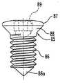
本発明の1つの重要な側面において、骨ネジ32は、図4に示すような固定角度ネジ50か、または図5に示すような可変角度ネジ60を構成する。まず図4を参照すると、固定角度ネジ50は、ネジ山が形成された軸部51を含む。ネジ山が形成された軸部51は椎体の海綿骨に係合するように構成されていることが好ましい。また、ネジ山が形成された軸部51は、それ自身にタッピングネジ山を含むが、特別に図示した実施例は、固定角度ネジ50を挿入するために前もって椎体を削りネジを切る必要がある。固定角度ネジ50は、ネジ山が形成された軸部51とネジのヘッド54との間に配置された中間部分52を有する。ネジ山が形成された軸部51は、標準的な機械加工した工程によって不完全ねじ部53が中間部分52に延びている。図4から理解できるように、中間部分52は、ネジ山が形成されていない短いセグメントを含む。この短いセグメントは、ここで説明した細長いプレート31を詳細に考慮する上で重要な外径D1を有する。 In one important aspect of the present invention, the
固定角度ネジ50のヘッド54は、駆動治具を受けるために治具溝55を含む。1つの特別の実施例において、治具溝55は、6角形の溝であり、他の実施例において、TORXタイプの溝である。ヘッド54は、切頭されたまたは平坦な上面56と上面56と中間部分52との間の球形面57とを含む。ヘッド54は、上面56と中間部分52との間に高さH1を有する。 The
1つの特定の実施例において、中間部分52と、さらに特別には、不完全ねじ部53とヘッド54の間の部分は、1.2mmの高さと4.05mmの直径とを有する。この特定の実施例におけるヘッド54の高さH1は、2.6mmの寸法を有する。この特定の実施例において、ヘッド54及び中間部分52の寸法は10mmと20mmとの間のネジ山が形成された軸部51の長さにおいて調整された。この特定の実施例において、骨ネジは、好ましくは、頚椎に係合するように形成される。特定の実施例の他の側面において、ネジ山が形成された軸部51の根本の直径は最後の根本の直径への第1の4つの渦巻き上にテーパが形成されており、この直径はこの特定の実施例では約2.43mmである。 In one particular embodiment, the
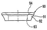
図5を参照すると、可変角度ネジ60の詳細を見ることができる。固定角度ネジ50と同様、可変角度ネジ60は、ネジ山が形成された軸部61と中間部分62とを含む。しかしながら、固定角度ネジ50に対して、中間部分62は、ネジ山が形成された軸部61の根本の直径にほぼ等しい外側の直径D2を有する。要するに、可変角度ネジ60の中間部分62の直径D2は、固定角度ネジ50の中間部分52の直径D1より小さい。固定角度ネジ50と同様、軸部61のネジ山は、中間部分62内へ出て、約0.8mmのネジ山が形成された部分62を残す。 Referring to FIG. 5, details of the
また、可変角度ネジ60は、切頭型の上面66から形成される治具溝65を有するヘッド64を含む。またヘッド64は、上面66と中間部分62との間に配置された球形面67を含む。可変角度ネジ60のヘッド64は、上面と中間部分との間に高さH2を有し、この高さH2は、固定角度ネジ50のヘッド54の高さH1より大きい。 The
可変角度ネジ60の特定の実施例において、ヘッド64は、約3.3mmの高さH2を有する。この大きな高さは、固定角度ネジ50の中間部分52の直径D1に対して中間部分64の小さい直径D2に寄与することができる。各ネジのヘッド54及びヘッド64は、特定の実施例において4.88mmである比較可能な直径を有する。可変角度ネジ60の場合において、球形面67の直径は、大きな弧の周囲に連続する。なぜならば、中間部分62は、直径が小さいからである。1つの特定の実施例において、中間部分62は、固定角度ネジ50の4.05mmの直径D1と比較して2.9mmの直径D2を有する。 In a particular embodiment of the
固定角度ネジ50と同様、可変角度ネジ60は、脊柱の異なる場所で使用するために10mmと20mmとの間の長さを備えている。 Like the fixed
固定角度ネジ50及び可変角度ネジ60の細長いプレート31への係合は、プレート自身の詳細な説明を必要とする。これらの詳細な説明は、図6ないし図14を参照して説明する。図6において、長いプレート31aを図示しているが、このプレートの種々の構造的な側面は、プレート31bないし31gの各々の間で繰り返される。前述したように、プレート31aは、波形の縁部を有し、波形のピークは椎骨の水準こぶ部に対応する。こぶ部の間のプレート材料は、プレートの嵩を最小限とし、移植時にさらに曲げることを必要とする領域にさらに薄いプレート幅を提供するように減じられている。特定の実施例において、プレートの長さにわたって、種々のパターンで複数のネジ穴34が設けられる。図6に図示した例において、ネジ穴は、プレートの両端の端部穴のパターン38、プレートの中央に配置された中間穴のパターン39、端部穴のパターン38及び中間穴のパターン39の間に配置された2つの4個の穴のパターン40とを有する。この場合において、穴のパターンは固定ネジ組立体33を必要とする。その結果、プレート31aは、本発明によって考慮された他のプレートの構成全体とともに、同心円的な固定溝71内に配置された雌ネジが形成された穴70を含む(図7参照)。図6及び図7に示すように、固定溝71は、ネジ穴34に隣接して交差するか重複する。端部穴パターン38の場合、固定溝71は、2つのネジ穴34に重複し、4つの穴のパターン40の場合、固定溝71は、ダイヤモンド状の形状に配列された4つのネジ穴34に重複する。Engagement of the fixed
この固定プレート組立体30の前の適用に合致するために、このプレートは、2つの自由度で湾曲している。特に、プレートの底面37は、図7に示すように、頚椎の後湾症の湾曲に適応するために、大きな半径Rに沿って曲がることができる。さらに、底面37は、椎体の曲率に対応するように図9に示すように、中間/側方の曲率Lを形成する。プレート31aは特定の脊柱の解剖学的構造及び椎骨の病状に適応させることが要求されるとき、椎骨水準のこぶ部35の間の長手方向の長さに沿って曲げることができる。In order to match the previous application of the fixed
プレート31aのネジ穴34は、細長いプレート31aと交差する軸75a(図11、図12を参照)の周りで測定された直径を有する球形溝75によって定義される(図7及び図9参照)。本発明の他の側面において、ネジ穴34は、プレート31の球形溝75と底面37との間に連通する円筒形穴77を有する。円筒形穴77は、軸75aに沿った直径を形成する。ドリルガイド、ドリル及び骨ネジ32の挿入を容易にするために、各ネジ穴34は、広がった溝79を含む。広がった溝79は、軸79aに沿ってテーパを備えたカウンタシンクとして形成することが好ましい(図11及び図13)。この広がった溝79は、図7,9及び13で最もよく示すように溝重複部分80で固定ネジ組立体33の固定溝71に重複する。 The
1つの特定の実施例において、球形溝75は、固定角度ネジ50,可変角度ネジ60のヘッド54,64の直径よりわずかに大きい5.0mmの直径で形成される。特定の実施例において、ネジ穴34の円筒形部分は4.1mmの直径で形成され、これも固定角度ネジ50の中間部分52の直径D1より僅かに大きい。もちろん、円筒形穴77の直径は、可変角度ネジ60の中間部分62の直径D2より著しく大きいことは理解しなければならない。 In one particular embodiment, the
特定の実施例において、球形溝75及び円筒形穴77の双方の軸75aは、プレートの長手方向の軸線の方向で見たときに、プレート31aの底面37にほぼ直角方向を向いている。要するに、軸75aは、プレートの中間/側方の曲率Lの方向にプレートに直角である。他方、特に端部穴パターン38を考慮するとき、ネジ穴34は、椎骨水準こぶ部35の間で変化する。この特定の実施例において、ひろがった溝79、及び特にその軸線79aは、その細長いプレート31aの内側で穴のパターンにおいて球形溝75の軸75aと同一線上にある。例えば、図6に示すように、広がった溝79は、中間穴パターン39のネジ穴34とほぼ同心円である。他方、端部穴パターン38での広がった溝79及び特に軸79aは、図14に示すように角度Aで片寄っている。特に、球形溝75の軸75aは、プレート31aの底面37から直角に対して約12°の角度Aで片寄っている。この方法において、骨ネジは、ネジ穴34に挿入するときプレートの端部に向かって外側を向いている。In a particular embodiment, the
固定ネジ組立体33の詳細は、図15ないし図17を考慮して収集することができる。この特定の実施例において、固定ネジ組立体33は、機械加工でネジ山86が形成された固定ネジ85を含む。1つの特定の実施例において、固定ネジ85は、椎体の貫通を可能にするように鋭い先端86aで終結している。固定ネジ85のヘッド87は、下方円錐面88と駆動治具を受けるために形成された治具溝89とを有する。 Details of the
また、固定ネジ組立体33は、外面91を有するワッシャ90を含む。特定の実施例において、外面91は、湾曲した凸面92によって定義される。また、ワッシャ90は、テーパが形成された穴94と連通するように延びているネジ穴93を有する。テーパが形成された穴94は、固定ネジ85のヘッド87の円錐面88に対して補完的に係合する構成を有する。固定ネジ85とワッシャ90との間の係合する円錐部分は、固定ネジ85がプレートに締め付けられるときワッシャ90の自己センタリング性能(self−centering capability)を提供する。このネジ穴93は、図17に示すように、プレート31aの雌ネジが形成された穴70と係合するために機械加工されたネジ山86を受けるような寸法である。図17に示すように、ワッシャ90の外面91は、広がった溝79と、隣接するネジ穴34の各球形溝75との間の溝重複部分80と交差する。特定の実施例において、固定溝71は、5.3m m の外径を有するワッシャ90を受ける6mmの直径を有する。この特定の実施例において、ワッシャ90の湾曲した凸面92は、ワッシャ90の最下端部分が約4.3mmのさらに小さい直径を有するように約2.5mmの半径で曲がっている。 The fixing
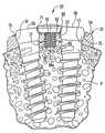
図18及び図19を参照すると、固定プレート組立体30の使用法が示されている。図18において、一対の固定角度ネジ50は、ネジ山が形成された軸部51がプレート31の下面37を越えて、椎体Vに突出するように各ネジ穴34内に配置される。固定角度ネジ50の中間部分52は、ネジ穴34の円筒形穴77を貫通している。固定角度ネジ50のヘッド54の球形面57は、固定角度ネジ50が椎体Vにネジ込まれるときネジ穴34の球形溝75に接触する。固定角度ネジ50が球形溝75内に完全に配置されるとき、中間部分52は、固定角度ネジ50がプレート31に関して回転するか、または移動することができないように円筒形穴77に関してきちんとした関係を提供する。 Referring to FIGS. 18 and 19, the use of the fixed
プレート31内での固定角度ネジ50の確かな固定を確保するために、固定ネジ組立体33は、2つの固定角度ネジ50のヘッド54に締め付けられる。特に、固定ネジ85は、ワッシャ90をネジヘッドに接触するように引くために雌ネジが形成された穴70にねじ込まれる。凸面92は、ヘッド54の球形面57に対して接触し、プレートの球形溝75内にネジヘッドをかたく接触させる。好ましくは、ワッシャ90は、固定溝71に十分に進んで固定角度ネジ50の上面56と実質的に面一になって停止する。固定位置において、ワッシャ90は、固定溝71内の底部には達しない。 In order to ensure a secure fixation of the fixed
本発明の他の側面において、固定ネジ組立体33は、プレートが椎骨に係合したときに、医師が固定ネジ組立体33で時間を浪費しないようにプレート31にゆるく固定する。特に、固定ネジ85は、3つかそれ以下のネジ山がプレートの底面37の下に突出するまでワッシャ90を通って雌ネジが形成された穴70に予めネジ込まれる。次に固定ネジ85は、雌ネジが形成された穴70を出るように除去されないか、戻ることができないように、プレートに最も近いネジで積み重ねられる。もちろん、固定ネジ85は、それが固定ネジ組立体33を作動可能にする必要があるとき、穴70を通って前進することができる。前述したように、固定ネジ85の鋭い先端86aは、皮質骨を貫通するように構成されていることが好ましい。プレートにネジを固定することによって、プレート31が最初に骨上に位置付けられるときに、鋭い先端86aは、椎骨Vを貫通する。この場合、固定ネジ85は、固定角度ネジ50が骨に移植されるとき、椎骨Vのプレートを配置する助けとし、一時的に安定するようにする。固定ネジ85によって提供される一時的な配置の特徴は、固定角度ネジ50を受けるためにドリルガイドが椎骨に穴を開け雌ネジを形成するときに使用することができる。 In another aspect of the invention, the
固定ネジ組立体33は、ワッシャ90が固定ネジ85をプレート31に取り付けるときにネジ穴34を開けるように動かすことができる。よって、固定ネジ組立体33がそのゆるんだ位置にあるときでさえも、固定角度ネジ50,可変角度ネジ60は、好ましくは、ワッシャ90をプレート31から引くことによってネジ穴34に挿入することができる。 The fixing
可変角度ネジ60の使用は、図19に示されている。固定ネジ組立体33は、プレート31内で可変角度ネジ60のヘッド64を固定するように上述したように機能する。特に、ワッシャ90の凸面92は、各可変角度ネジ60の球形面67に接触し、圧力を加える。しかしながら、可変角度ネジ60によれば、中間部分62は、ネジ穴34の円筒形穴77にはきちんとは嵌合しない。よって、各可変角度ネジ60のヘッド64が球形溝75内に固定されている場合であっても、可変角度ネジ60はプレートに対して及び球形溝75及び円筒形穴77の軸線に対して角度を形成することができる。角度形成の程度は、円筒形穴77と可変角度ネジ60の中間部分62との間の直径の差によって制限されることは理解すべきである。1つの好ましい実施例において、その相対的な直径は、球形溝75と円筒形穴77の軸75aから20°までの角度形成を許容する。 The use of
移植中、可変角度ネジ60の可変角度の能力は、定義された角度の制限(1つの特定の実施例においては20°)内の角度で医師が椎骨内に骨ネジを配置することができるようにする。よって、可変角度ネジ60は、椎骨の解剖学的な形状に関して骨ネジの向きを決めるために固定角度ネジ50よりも大きな融通性を提供する。さらに、この可変角度能力は、固定プレート組立体30が患者内に移植されるときにネジとプレートとの間の制限された小さな動きを可能にする。要するに、脊柱が荷重を受け、荷重がネジとプレートを介して伝達されるとき、プレート及び椎骨が互いに平行移動する。可変角度ネジ60は、球形溝75内で回転することによってこの相対運動を受け入れる。他方、この固定角度ネジ50は、この相対運動を防止する。固定角度ネジ50または可変角度ネジ60を使用する選択は、処置すべき病状に依存して医師にゆだねることができる。本発明による固定プレート組立体30は、外科手術の間のいかなる時点でもこの選択ができるようにすることができる。 During implantation, the variable angle capability of the
本発明の他の実施例は、図20ないし図23に示されている。この実施例において、他の固定機構が設けられる。プレート組立体100は、骨ネジ102を受ける細長いプレート101を有する。固定ネジ組立体103は、プレート内に骨ネジを固定するために設けられる。このプレート101は、骨ネジ102の球形ヘッド115を受けるために球形溝105を形成する。骨ネジ102のネジ山が形成された軸部114は球形溝105を通して突出している。骨ネジ102及び球形溝105は上述した同じ部品と同様であることは理解できよう。 Another embodiment of the present invention is shown in FIGS. In this embodiment, another fixing mechanism is provided. The
この実施例によれば、さらにプレートは、骨ネジ102のための球形溝105に隣接して配置された雌ネジが形成された穴106及び同心円的な固定溝107を含む。この球形溝105及び固定溝107は、固定重複部分108で接触する。切り欠き部分110がこの実施例で固定溝107を横切って延びている。 According to this embodiment, the plate further includes a female threaded
固定ネジ組立体103は、ワッシャ120及び固定ネジ121を有する。先の固定ネジと同様、固定ネジ121は、機械ネジ山122と拡大ヘッド123とを含む。拡大ヘッド123はワッシャ120の溝124内に配置され、機械ネジ山122は穴125を通して突出している。機械ネジ山122は、プレート101の雌ネジが形成された穴106に係合するように構成されている。固定ネジ121は、前の実施例に関して説明したようにプレート101に取り付けられる。 The fixing
ワッシャ120は、前の実施例のワッシャと同様に機能しながら前述したワッシャとは異なる構成を有する。このワッシャ90と同様に、ワッシャ120は、骨ネジ102の球形ヘッド115とかみあうように凸形状が好ましい外周面127を有する。しかしながら、1つの変形例において、ワッシャ120は、外周面127に切り出し部分128を含む。切り出し部分128は、図21に示すようにワッシャ120が第1の位置にあるとき、球形溝105と一致するように配置される。ワッシャ120のこの構造は、ワッシャ120が骨ネジ102を妨げなく挿入するための球形溝105を妨げることなく開けることができる。 The
ある実施例によれば、ワッシャ120は、ワッシャ120に直径方向に対向する位置に2つのこのような切り出し部分128を備えている。さらに好ましくは、切り出し部分128は、プレート101の球形溝105の相対的な配置に位置合わせされている。例えば、図3(f)に示すように3つの穴のパターン43用のワッシャ120は、120°の間隔で3つの切り出し部分128を有する。同様に、図3(a)の4つの穴のパターン40とともに使用するように変形されたワッシャ120は、ワッシャ120の外周面127で90°の間隔を置いた4つの切り出し部分128を有する。 According to one embodiment, the
骨ネジ102が適当な球形溝105を通して移植されると、ワッシャ120は、図22に示す固定位置に回転することができる。この位置において、切り出し部分128は、ワッシャ120、さらに詳細には外周面127が球形溝105に重複するように球形溝105から離れるように回転する。さらに前のワッシャからさらに変形した例において、ワッシャ120は、ワッシャ120の下側に多数のキー129を有する。キー129は、ワッシャ120が図22に示す固定位置にあるとき、プレート101の対応する切り欠き部分110内に配置されるように形成される。骨ネジ102が移植され、ワッシャ120がその固定位置に回転するとき、キー129は、固定ネジ121を締め付けながらワッシャ120の位置を固定するために切り欠き部分110に落下する。 When the
本発明を図面及び詳細な説明で詳細に図示し説明したが、単なる例示として、制限されないものとして考慮すべきである。好ましい実施の形態を示し説明したのみで、本発明の精神内に接触する変形または改造のすべてを保護することが望ましいことは理解できよう。 Although the invention has been illustrated and described in detail in the drawings and detailed description, it should be considered as illustrative and not restrictive. It will be appreciated that, while only preferred embodiments have been shown and described, it is desirable to protect all variations or modifications that come within the spirit of the invention.
Claims (20)
Translated fromJapanese前記第1および第2の穴のいずれか一方を通して配置することができる第1の細長い軸部を有する第1の骨係合固定具であって、前記第1の軸部が前記第1および第2の穴の前記円筒形部分の前記直径より小さい寸法にされており、これにより前記第1の軸部が前記プレートの前記底面に関して複数の方向のうちのいずれかの方向をとることができるようになっている、第1の骨係合固定具と、
前記第1および第2の穴のいずれか他方を通して配置することができる第2の細長い軸部を有する第2の骨係合固定具であって、前記第2の軸部がネジ山が設けられていない中間部分を有し、前記第2の軸部の前記ネジ山が設けられていない中間部分が、前記第2の細長い軸部と前記プレートの前記底面との間で固定された方向を提供するように前記第1および第2の穴の前記他方の前記円筒形部分の内面に係合するようになっている、第2の骨係合固定具と、
を備えた骨固定装置。E Bei the top andbottom,an elongated plate, wherein the top surface and at least first and second holes extending between the bottom surface isprovided, a cylindrical portion in which the first and second holes having a respective diameter A plate, wherein the diameters of the cylindrical portions are equal to each other;
A first bone engaging fastener having a first elongated shank which can be located either throughone of the first and second holes, said first shaft portion of the first and second beingthe diameter smaller than the dimensionof the cylindrical portion of the second hole can take any direction of the plurality of directions with respect tothis by the bottomsurface of the first shaft portion is the plate A first bone engagement fixture,
A second bone engaging fastener having a second elongated shank which can be placed throughthe other of said first and second holes, said second shaft portion is provided threads A non-intermediate portion, and the non-threaded intermediate portion of the second shank provides a fixed direction between the second elongate shank and the bottom surface of the plate A second bone engagement fixture adapted to engagethe inner surface of theother cylindrical portion of the first and second holes to
A bone anchoring device.
前記第2の細長い軸部には骨係合ネジ山が形成され、前記第2の細長い軸部がその一端に第2の拡大ヘッドを含み、前記ネジ山が設けられていない中間部分が前記第2の拡大ヘッドと前記骨係合ネジ山との間に配置される、請求項1に記載の骨固定装置。A bone engaging thread is formed on the first elongate shank, the first elongate shank including a first enlarged head at one end;
A bone engaging thread is formed on the second elongate shaft, the second elongate shaft includes a second enlarged head at one end, and an intermediate portion without the thread is the first The bone anchoring device according to claim 1, which is arranged between two enlargement heads and the bone engaging thread.
前記第2の骨係合固定具が、前記第2の拡大ヘッドを前記プレートの前記上面に隣接させて、前記プレートの前記上面から前記第1の穴を通しても第2の穴を通しても挿入可能である、請求項2に記載の骨固定装置。Said first bone engaging fastener,even through the firsthole from the top surface of the first said plate an enlarged head by adjacent said upper surface of said plate isalso insertable through the second bore ,
The second bone engaging fixture canbe inserted from the top surface of the platethrough the firsthole or through the second hole with the second expansion head adjacent to the top surface of the plate. The bone fixation device according to claim 2, wherein the device is a bone fixation device.
前記第2の骨係合固定具の前記中間部分が前記第2の直径とほぼ等しい第4の直径を有する、請求項4に記載の骨固定装置。The first bone engagement fixture has an intermediate portion adjacent to a first expansion head formed at one end of the first elongated shaft portion, and the first bone engagement fixture of the first bone engagement fixture. The middle portion has a third diameter substantially smaller than the second diameter;
The bone fixation device of claim 4, wherein the intermediate portion of the second bone engagement fixture has a fourth diameter substantially equal to the second diameter.
前記第1及び第2の穴の間で前記プレートに形成された固定具穴と、
中央穴及び前記中央穴に連通する溝を形成し、前記第1及び第2の穴内に配置された前記骨係合固定具に接触するように形成されたワッシャと、
前記ワッシャの前記溝内に配置されるように形成されたヘッドと前記中央穴を貫通し前記プレートの前記固定具穴に係合する細長い軸部とを有する固定具と、
を有する請求項10に記載の骨固定装置。The fixing screw assembly further includes:
A fixture hole formed in the plate between the first and second holes;
A washer formed to form a central hole and a groove communicating with the central hole and to contact the bone engaging fixture disposed in the first and second holes;
A fixture having a head formed to be disposed in the groove of the washer and an elongated shaft portion that penetrates the central hole and engages the fixture hole of the plate;
The bone anchoring device according to claim 10, comprising:
前記第1の開口に隣接して配置可能な第1の軸部分を有する第1の固定具であって、前記第1の軸部分が、前記第1の固定具が前記プレートの前記底面に関し実質的に固定角度で配置可能となるような、前記第1の開口寸法に実質的に対応する第1の軸部寸法を有する、第1の固定具と、
前記第2の開口に隣接して配置可能な第2の軸部分を有する第2の固定具であって、前記第2の軸部分が、前記第2の固定具が前記プレートの前記底面に対して複数の角度で配置可能となるような、前記第2の開口寸法より実質的に小さい第2の軸部寸法を有する、第2の固定具と、
を備える、骨固定装置。A plate having a second opening of the first opening and the second opening dimension of the first opening dimension,have a top surface and a bottomsurface, said first opening dimension and the second opening dimension is Equal to each other, the plate,
A first fixture having a first shaft portion that can be disposed adjacent to the first opening, wherein the first shaft portion is substantially in relation to the bottom surface of the plate. A first fixture having a first shank dimension substantially corresponding to the first opening dimension such that the first fixture dimension can be placed at a fixed angle,
A second fixture having a second shaft portion that can be disposed adjacent to the second opening, wherein the second shaft portion is configured such that the second fixture is relative to the bottom surface of the plate. A second fixture having a second shank dimension that is substantially smaller than the second opening dimension, such that it can be arranged at a plurality of angles;
A bone anchoring device comprising:
前記第1の開口寸法が第1の長手方向開口寸法を有し、前記第1の軸部寸法が第1の長手方向軸部寸法を有し、前記第1の長手方向軸部寸法が前記第1の長手方向開口寸法に実質的に等しく、
前記第2の開口寸法が第2の長手方向開口寸法を有し、前記第2の軸部寸法が第2の長手方向軸部寸法を有し、前記第2の長手方向軸部寸法が前記第2の長手方向開口寸法より実質的に小さい、
請求項12に記載の骨固定装置。When viewed in the direction of the longitudinal axis of the plate,
The first opening dimension has a first longitudinal opening dimension, the first shank dimension has a first longitudinal shank dimension, and the first longitudinal shank dimension is the first longitudinal dimension. Substantially equal to the longitudinal opening dimension of 1;
The second opening dimension has a second longitudinal opening dimension, the second shaft dimension has a second longitudinal shaft dimension, and the second longitudinal shaft dimension is the first dimension. Substantially less than the longitudinal opening dimension of 2;
The bone anchoring device according to claim 12.
前記第1の開口周部の前記直径に実質的に対応する直径を有する第1の軸部周部を有する第1の軸部を有する第1の固定具と、
前記第2の開口周部の前記直径より実質的に小さい直径を有する第2の軸部周部を有する第2の軸部を有する第2の固定具と
を有し、
前記第1の固定具は、前記プレートの前記底面に対して実質的に固定された角度で配置可能であり、
前記第2の固定具は、前記プレートの前記底面に対して複数の角度で配置可能である、骨固定装置。A plate having a first opening having a first opening periphery, a second opening having a second opening periphery, a top surface, and a bottom surface, wherein the first opening periphery and the second opening Each of the opening perimeters has a diameter, the diameter of the first opening perimeter and the diameter of the second opening perimeter are equal to each other ,
A first fastener having a first shaft portion having a first shaft portion peripheryhaving a diameter substantially corresponding tothe diameter of the first opening periphery,
A second fixture having a second shaft portion having a second shaft portion peripheryhaving a diameter substantially smaller than thediameter of the second opening periphery;
The first fixture may be disposed at a substantially fixed angle relative to the bottom surface of the plate;
The bone anchoring device, wherein the second fastener can be arranged at a plurality of angles with respect to the bottom surface of the plate.
前記第1の開口内に配置可能な第1の軸部分を有する第1の固定具であって、前記第1の軸部分が、前記第1の軸部分が前記第1の開口内に配置されたときに前記プレートが前記第1の軸部分の周りで前記第1の軸部分に接触するような、前記第1の開口寸法に実質的に対応する第1の軸部寸法を有する、第1の固定具と、
前記第2の開口内に配置可能な第2の軸部分を有する第2の固定具であって、前記第2の軸部分が、前記第2の軸部分が前記第2の開口内に配置されたときに前記プレートが前記第2の軸部分の周りで間隔を空けるような、前記第2の開口寸法より実質的に小さい第2の軸部寸法を有する、第2の固定具と、
を備え、
前記第1の固定具が、前記プレートの前記底面に関して実質的に固定角度で配置可能であり、
前記第2の固定具が、前記プレートの前記底部に関して複数の角度で配置可能である、骨固定装置。A plate having a second opening of the first opening and the second opening dimension of the first opening dimension,have a top surface and a bottomsurface, and said first opening dimension and the second opening dimension is Equal to each other, the plate,
A first fixture having a first shaft portion that can be disposed in the first opening, wherein the first shaft portion is disposed in the first opening. Having a first shank dimension substantially corresponding to the first opening dimension such that the plate contacts the first shank part about the first shank part when A fixture of
A second fixture having a second shaft portion that can be disposed in the second opening, wherein the second shaft portion is disposed in the second opening. A second fixture having a second shank dimension substantially smaller than the second opening dimension such that the plate is spaced around the second shank portion when
With
The first fixture can be disposed at a substantially fixed angle with respect to the bottom surface of the plate;
The bone fixation device, wherein the second fixture can be disposed at a plurality of angles with respect to the bottom of the plate.
Applications Claiming Priority (1)
| Application Number | Priority Date | Filing Date | Title |
|---|---|---|---|
| US85690297A | 1997-05-15 | 1997-05-15 |
Related Parent Applications (1)
| Application Number | Title | Priority Date | Filing Date |
|---|---|---|---|
| JP54941798ADivisionJP4106096B2 (en) | 1997-05-15 | 1998-05-12 | Anterior cervical plate device |
Publications (3)
| Publication Number | Publication Date |
|---|---|
| JP2008100101A JP2008100101A (en) | 2008-05-01 |
| JP2008100101A5 JP2008100101A5 (en) | 2010-03-04 |
| JP4473303B2true JP4473303B2 (en) | 2010-06-02 |
Family
ID=25324748
Family Applications (3)
| Application Number | Title | Priority Date | Filing Date |
|---|---|---|---|
| JP54941798AExpired - LifetimeJP4106096B2 (en) | 1997-05-15 | 1998-05-12 | Anterior cervical plate device |
| JP2007033279AExpired - LifetimeJP4436844B2 (en) | 1997-05-15 | 2007-02-14 | Anterior cervical plate device |
| JP2007316481AExpired - LifetimeJP4473303B2 (en) | 1997-05-15 | 2007-12-07 | Anterior cervical plate device |
Family Applications Before (2)
| Application Number | Title | Priority Date | Filing Date |
|---|---|---|---|
| JP54941798AExpired - LifetimeJP4106096B2 (en) | 1997-05-15 | 1998-05-12 | Anterior cervical plate device |
| JP2007033279AExpired - LifetimeJP4436844B2 (en) | 1997-05-15 | 2007-02-14 | Anterior cervical plate device |
Country Status (12)
| Country | Link |
|---|---|
| US (4) | US6152927A (en) |
| EP (3) | EP0984728B1 (en) |
| JP (3) | JP4106096B2 (en) |
| AT (2) | ATE247422T1 (en) |
| AU (1) | AU731855B2 (en) |
| CA (1) | CA2289681C (en) |
| DE (2) | DE69835968T2 (en) |
| DK (1) | DK0984728T3 (en) |
| ES (2) | ES2272886T3 (en) |
| PT (1) | PT984728E (en) |
| WO (1) | WO1998051226A2 (en) |
| ZA (1) | ZA983955B (en) |
Families Citing this family (446)
| Publication number | Priority date | Publication date | Assignee | Title |
|---|---|---|---|---|
| US7201751B2 (en) | 1997-01-02 | 2007-04-10 | St. Francis Medical Technologies, Inc. | Supplemental spine fixation device |
| US7306628B2 (en) | 2002-10-29 | 2007-12-11 | St. Francis Medical Technologies | Interspinous process apparatus and method with a selectably expandable spacer |
| US7959652B2 (en) | 2005-04-18 | 2011-06-14 | Kyphon Sarl | Interspinous process implant having deployable wings and method of implantation |
| US6068630A (en) | 1997-01-02 | 2000-05-30 | St. Francis Medical Technologies, Inc. | Spine distraction implant |
| ES2297092T3 (en) | 1997-02-11 | 2008-05-01 | Warsaw Orthopedic, Inc. | PREVIOUS CERVICAL PLATE OF UNIQUE BLOCK. |
| US6139550A (en)* | 1997-02-11 | 2000-10-31 | Michelson; Gary K. | Skeletal plating system |
| ZA983955B (en)* | 1997-05-15 | 2001-08-13 | Sdgi Holdings Inc | Anterior cervical plating system. |
| US6454769B2 (en)* | 1997-08-04 | 2002-09-24 | Spinal Concepts, Inc. | System and method for stabilizing the human spine with a bone plate |
| FR2778088B1 (en)* | 1998-04-30 | 2000-09-08 | Materiel Orthopedique En Abreg | ANTERIOR IMPLANT, PARTICULARLY FOR THE CERVICAL RACHIS |
| US6533786B1 (en)* | 1999-10-13 | 2003-03-18 | Sdgi Holdings, Inc. | Anterior cervical plating system |
| US20040220571A1 (en)* | 1998-04-30 | 2004-11-04 | Richard Assaker | Bone plate assembly |
| WO2000059388A1 (en)* | 1999-04-05 | 2000-10-12 | Surgical Dynamics, Inc. | Artificial spinal ligament |
| US7094239B1 (en)* | 1999-05-05 | 2006-08-22 | Sdgi Holdings, Inc. | Screws of cortical bone and method of manufacture thereof |
| EP1370183B1 (en) | 1999-07-07 | 2014-02-19 | Children's Hospital Medical Center | Spinal correction system |
| US6692503B2 (en)* | 1999-10-13 | 2004-02-17 | Sdgi Holdings, Inc | System and method for securing a plate to the spinal column |
| US6331179B1 (en)* | 2000-01-06 | 2001-12-18 | Spinal Concepts, Inc. | System and method for stabilizing the human spine with a bone plate |
| US6893444B2 (en)* | 2000-02-01 | 2005-05-17 | Hand Innovations, Llc | Bone fracture fixation systems with both multidirectional and unidirectional stabilization pegs |
| US6767351B2 (en) | 2000-02-01 | 2004-07-27 | Hand Innovations, Inc. | Fixation system with multidirectional stabilization pegs |
| US6706046B2 (en) | 2000-02-01 | 2004-03-16 | Hand Innovations, Inc. | Intramedullary fixation device for metaphyseal long bone fractures and methods of using the same |
| US20040153073A1 (en) | 2000-02-01 | 2004-08-05 | Hand Innovations, Inc. | Orthopedic fixation system including plate element with threaded holes having divergent axes |
| US7857838B2 (en) | 2003-03-27 | 2010-12-28 | Depuy Products, Inc. | Anatomical distal radius fracture fixation plate |
| US7695502B2 (en) | 2000-02-01 | 2010-04-13 | Depuy Products, Inc. | Bone stabilization system including plate having fixed-angle holes together with unidirectional locking screws and surgeon-directed locking screws |
| US6293949B1 (en)* | 2000-03-01 | 2001-09-25 | Sdgi Holdings, Inc. | Superelastic spinal stabilization system and method |
| US6312431B1 (en)* | 2000-04-24 | 2001-11-06 | Wilson T. Asfora | Vertebrae linking system |
| FR2810532B1 (en) | 2000-06-26 | 2003-05-30 | Stryker Spine Sa | BONE IMPLANT WITH ANNULAR LOCKING MEANS |
| AU757023B2 (en) | 2000-06-26 | 2003-01-30 | Stryker European Holdings I, Llc | Bone screw retaining system |
| US6740088B1 (en) | 2000-10-25 | 2004-05-25 | Sdgi Holdings, Inc. | Anterior lumbar plate and method |
| US6503250B2 (en)* | 2000-11-28 | 2003-01-07 | Kamaljit S. Paul | Bone support assembly |
| US20050010227A1 (en)* | 2000-11-28 | 2005-01-13 | Paul Kamaljit S. | Bone support plate assembly |
| US6413259B1 (en) | 2000-12-14 | 2002-07-02 | Blackstone Medical, Inc | Bone plate assembly including a screw retaining member |
| US6702817B2 (en) | 2001-01-19 | 2004-03-09 | Aesculap Ag & Co. Kg | Locking mechanism for a bone screw |
| US20020115742A1 (en)* | 2001-02-22 | 2002-08-22 | Trieu Hai H. | Bioactive nanocomposites and methods for their use |
| US7344539B2 (en) | 2001-03-30 | 2008-03-18 | Depuy Acromed, Inc. | Intervertebral connection system |
| FR2823096B1 (en)* | 2001-04-06 | 2004-03-19 | Materiel Orthopedique En Abreg | PLATE FOR LTE AND LTE VERTEBRATE OSTEOSYNTHESIS DEVICE, OSTEOSYNTHESIS DEVICE INCLUDING SUCH A PLATE, AND INSTRUMENT FOR LAYING SUCH A PLATE |
| RU2197912C2 (en)* | 2001-04-17 | 2003-02-10 | Закрытое акционерное общество "КОНМЕТ Инкорпорейтед" | Surgical and device method for treating spondylolisthesis |
| US6599290B2 (en) | 2001-04-17 | 2003-07-29 | Ebi, L.P. | Anterior cervical plating system and associated method |
| RU2197914C2 (en)* | 2001-04-17 | 2003-02-10 | Закрытое акционерное общество "КОНМЕТ Инкорпорейтед" | Device for stabilizing lumar segment of the vertebral column |
| US20050240187A1 (en) | 2004-04-22 | 2005-10-27 | Huebner Randall J | Expanded fixation of bones |
| US7326212B2 (en) | 2002-11-19 | 2008-02-05 | Acumed Llc | Bone plates with reference marks |
| US7717945B2 (en) | 2002-07-22 | 2010-05-18 | Acumed Llc | Orthopedic systems |
| US7537604B2 (en) | 2002-11-19 | 2009-05-26 | Acumed Llc | Bone plates with slots |
| JP4283665B2 (en)* | 2001-06-04 | 2009-06-24 | ウォーソー・オーソペディック・インコーポレーテッド | Dynamic plate for anterior cervical spine with movable segments |
| US7186256B2 (en)* | 2001-06-04 | 2007-03-06 | Warsaw Orthopedic, Inc. | Dynamic, modular, single-lock anterior cervical plate system having assembleable and movable segments |
| US7097645B2 (en) | 2001-06-04 | 2006-08-29 | Sdgi Holdings, Inc. | Dynamic single-lock anterior cervical plate system having non-detachably fastened and moveable segments |
| CA2443429C (en) | 2001-06-04 | 2010-08-10 | Gary Karlin Michelson | Anterior cervical plate system having vertebral body engaging anchors, connecting plate, and method for installation thereof |
| US7044952B2 (en)* | 2001-06-06 | 2006-05-16 | Sdgi Holdings, Inc. | Dynamic multilock anterior cervical plate system having non-detachably fastened and moveable segments |
| US7041105B2 (en)* | 2001-06-06 | 2006-05-09 | Sdgi Holdings, Inc. | Dynamic, modular, multilock anterior cervical plate system having detachably fastened assembleable and moveable segments |
| US6890335B2 (en) | 2001-08-24 | 2005-05-10 | Zimmer Spine, Inc. | Bone fixation device |
| AU2002349962B2 (en)* | 2001-10-19 | 2006-04-06 | Baylor College Of Medicine | Bone compression devices and systems and methods of contouring and using same |
| DE10152094C2 (en)* | 2001-10-23 | 2003-11-27 | Biedermann Motech Gmbh | Bone fixation device |
| US7766947B2 (en) | 2001-10-31 | 2010-08-03 | Ortho Development Corporation | Cervical plate for stabilizing the human spine |
| US6679883B2 (en) | 2001-10-31 | 2004-01-20 | Ortho Development Corporation | Cervical plate for stabilizing the human spine |
| US7008426B2 (en)* | 2001-12-14 | 2006-03-07 | Paul Kamaljit S | Bone treatment plate assembly |
| US6755833B1 (en)* | 2001-12-14 | 2004-06-29 | Kamaljit S. Paul | Bone support assembly |
| US7070599B2 (en)* | 2002-07-24 | 2006-07-04 | Paul Kamaljit S | Bone support assembly |
| CA2471843C (en)* | 2001-12-24 | 2011-04-12 | Synthes (U.S.A.) | Device for osteosynthesis |
| USD505205S1 (en) | 2002-02-01 | 2005-05-17 | Spinal Concepts, Inc. | Bone plate system extender plate |
| US6695846B2 (en) | 2002-03-12 | 2004-02-24 | Spinal Innovations, Llc | Bone plate and screw retaining mechanism |
| US20030187443A1 (en)* | 2002-03-27 | 2003-10-02 | Carl Lauryssen | Anterior bone plate system and method of use |
| US20030187509A1 (en)* | 2002-04-01 | 2003-10-02 | Lemole G. Michael | Modulus plating system and method |
| US7025769B1 (en)* | 2002-06-04 | 2006-04-11 | Nuvasive, Inc. | Surgical fixation system and related methods |
| US7077843B2 (en) | 2002-06-24 | 2006-07-18 | Lanx, Llc | Cervical plate |
| US7175623B2 (en)* | 2002-06-24 | 2007-02-13 | Lanx, Llc | Cervical plate with backout protection |
| US7001389B1 (en) | 2002-07-05 | 2006-02-21 | Navarro Richard R | Fixed and variable locking fixation assembly |
| US6989012B2 (en)* | 2002-07-16 | 2006-01-24 | Sdgi Holdings, Inc. | Plating system for stabilizing a bony segment |
| CN1309352C (en)* | 2002-07-22 | 2007-04-11 | 精密医疗责任有限公司 | Bone fusion system |
| US7862597B2 (en)* | 2002-08-22 | 2011-01-04 | Warsaw Orthopedic, Inc. | System for stabilizing a portion of the spine |
| US20040111090A1 (en)* | 2002-10-03 | 2004-06-10 | The University Of North Carolina At Chapel Hill | Modification of percutaneous intrafocal plate system |
| CA2504215A1 (en)* | 2002-10-28 | 2004-05-13 | Blackstone Medical, Inc. | Bone plate assembly provided with screw locking mechanisms |
| US7909853B2 (en) | 2004-09-23 | 2011-03-22 | Kyphon Sarl | Interspinous process implant including a binder and method of implantation |
| US7931674B2 (en) | 2005-03-21 | 2011-04-26 | Kyphon Sarl | Interspinous process implant having deployable wing and method of implantation |
| US7833246B2 (en) | 2002-10-29 | 2010-11-16 | Kyphon SÀRL | Interspinous process and sacrum implant and method |
| US8070778B2 (en) | 2003-05-22 | 2011-12-06 | Kyphon Sarl | Interspinous process implant with slide-in distraction piece and method of implantation |
| US7549999B2 (en) | 2003-05-22 | 2009-06-23 | Kyphon Sarl | Interspinous process distraction implant and method of implantation |
| US8048117B2 (en) | 2003-05-22 | 2011-11-01 | Kyphon Sarl | Interspinous process implant and method of implantation |
| US7682392B2 (en) | 2002-10-30 | 2010-03-23 | Depuy Spine, Inc. | Regenerative implants for stabilizing the spine and devices for attachment of said implants |
| AU2003294414B2 (en) | 2002-11-19 | 2009-03-12 | Acumed Llc | Deformable bone plates |
| AU2003294342A1 (en) | 2002-11-19 | 2004-06-15 | Acumed Llc | Guide system for bone-repair devices |
| US20050187551A1 (en)* | 2002-12-02 | 2005-08-25 | Orbay Jorge L. | Bone plate system with bone screws fixed by secondary compression |
| US7811312B2 (en)* | 2002-12-04 | 2010-10-12 | Morphographics, Lc | Bone alignment implant and method of use |
| US7780664B2 (en) | 2002-12-10 | 2010-08-24 | Depuy Products, Inc. | Endosteal nail |
| US7175624B2 (en) | 2002-12-31 | 2007-02-13 | Depuy Spine, Inc. | Bone plate and screw system allowing bi-directional assembly |
| US7914561B2 (en) | 2002-12-31 | 2011-03-29 | Depuy Spine, Inc. | Resilient bone plate and screw system allowing bi-directional assembly |
| US7048739B2 (en)* | 2002-12-31 | 2006-05-23 | Depuy Spine, Inc. | Bone plate and resilient screw system allowing bi-directional assembly |
| US7341591B2 (en) | 2003-01-30 | 2008-03-11 | Depuy Spine, Inc. | Anterior buttress staple |
| US8172885B2 (en) | 2003-02-05 | 2012-05-08 | Pioneer Surgical Technology, Inc. | Bone plate system |
| US7278997B1 (en) | 2003-03-07 | 2007-10-09 | Theken Spine, Llc | Instrument guide and implant holder |
| US20040193155A1 (en)* | 2003-03-27 | 2004-09-30 | Hand Innovations, Inc. | Fracture fixation plate with particular plate hole and fastener engagement and methods of using the same |
| US7935123B2 (en)* | 2003-04-09 | 2011-05-03 | Depuy Acromed, Inc. | Drill guide with alignment feature |
| US7416553B2 (en) | 2003-04-09 | 2008-08-26 | Depuy Acromed, Inc. | Drill guide and plate inserter |
| US7909829B2 (en) | 2003-06-27 | 2011-03-22 | Depuy Spine, Inc. | Tissue retractor and drill guide |
| US7776047B2 (en) | 2003-04-09 | 2010-08-17 | Depuy Spine, Inc. | Guide for spinal tools, implants, and devices |
| US20170020683A1 (en) | 2003-04-21 | 2017-01-26 | Rsb Spine Llc | Bone plate stabilization system and method for its use |
| US7169150B2 (en)* | 2003-04-25 | 2007-01-30 | Warsaw Orthopedic, Inc. | Non-metallic orthopedic plate |
| US6945973B2 (en)* | 2003-05-01 | 2005-09-20 | Nuvasive, Inc. | Slidable bone plate system |
| US7951176B2 (en) | 2003-05-30 | 2011-05-31 | Synthes Usa, Llc | Bone plate |
| DE10326643A1 (en)* | 2003-06-11 | 2004-12-30 | Mückter, Helmut, Dr. med. Dipl.-Ing. | Osteosynthesis plate or comparable implant with ball sleeve |
| US7309340B2 (en) | 2003-06-20 | 2007-12-18 | Medicinelodge, Inc. | Method and apparatus for bone plating |
| WO2004112587A2 (en)* | 2003-06-20 | 2004-12-29 | Acumed Llc | Bone plates with intraoperatively tapped apertures |
| US7909848B2 (en) | 2003-06-27 | 2011-03-22 | Depuy Spine, Inc. | Tissue retractor and guide device |
| US7731721B2 (en) | 2003-07-16 | 2010-06-08 | Synthes Usa, Llc | Plating system with multiple function drill guide |
| KR20060123057A (en) | 2003-08-01 | 2006-12-01 | 신세스 게엠바하 | Drill guide assembly for bone fixation |
| US20050033430A1 (en) | 2003-08-05 | 2005-02-10 | Russell Powers | Surgical kit and method for providing sterilized equipment for use in spinal surgery |
| US7625375B2 (en)* | 2003-08-06 | 2009-12-01 | Warsaw Orthopedic, Inc. | Systems and techniques for stabilizing the spine and placing stabilization systems |
| US7357804B2 (en) | 2003-08-13 | 2008-04-15 | Synthes (U.S.A.) | Quick-release drill-guide assembly for bone-plate |
| DE20321551U1 (en)* | 2003-08-26 | 2007-12-27 | Synthes Gmbh | bone plate |
| US11259851B2 (en) | 2003-08-26 | 2022-03-01 | DePuy Synthes Products, Inc. | Bone plate |
| US7635365B2 (en) | 2003-08-28 | 2009-12-22 | Ellis Thomas J | Bone plates |
| US20050049595A1 (en)* | 2003-09-03 | 2005-03-03 | Suh Sean S. | Track-plate carriage system |
| US7909860B2 (en) | 2003-09-03 | 2011-03-22 | Synthes Usa, Llc | Bone plate with captive clips |
| US7857839B2 (en)* | 2003-09-03 | 2010-12-28 | Synthes Usa, Llc | Bone plate with captive clips |
| US8105367B2 (en) | 2003-09-29 | 2012-01-31 | Smith & Nephew, Inc. | Bone plate and bone plate assemblies including polyaxial fasteners |
| US7182782B2 (en) | 2003-09-30 | 2007-02-27 | X-Spine Systems, Inc. | Spinal fusion system and method for fusing spinal bones |
| US8821553B2 (en) | 2003-09-30 | 2014-09-02 | X-Spine Systems, Inc. | Spinal fusion system utilizing an implant plate having at least one integral lock |
| US8372152B2 (en) | 2003-09-30 | 2013-02-12 | X-Spine Systems, Inc. | Spinal fusion system utilizing an implant plate having at least one integral lock and ratchet lock |
| US9078706B2 (en) | 2003-09-30 | 2015-07-14 | X-Spine Systems, Inc. | Intervertebral fusion device utilizing multiple mobile uniaxial and bidirectional screw interface plates |
| US7641701B2 (en) | 2003-09-30 | 2010-01-05 | X-Spine Systems, Inc. | Spinal fusion system and method for fusing spinal bones |
| US8062367B2 (en) | 2003-09-30 | 2011-11-22 | X-Spine Systems, Inc. | Screw locking mechanism and method |
| US7306605B2 (en) | 2003-10-02 | 2007-12-11 | Zimmer Spine, Inc. | Anterior cervical plate |
| US8182485B1 (en) | 2003-11-21 | 2012-05-22 | Toby Orthopaedics, Llc | Fracture fixation system |
| US8182518B2 (en)* | 2003-12-22 | 2012-05-22 | Life Spine, Inc. | Static and dynamic cervical plates and cervical plate constructs |
| US7635366B2 (en)* | 2003-12-29 | 2009-12-22 | Abdou M Samy | Plating system for bone fixation and method of implantation |
| EP1708629A4 (en)* | 2004-01-08 | 2011-08-17 | David Mark Allison | Bone fixing device |
| US7678137B2 (en) | 2004-01-13 | 2010-03-16 | Life Spine, Inc. | Pedicle screw constructs for spine fixation systems |
| US8574268B2 (en) | 2004-01-26 | 2013-11-05 | DePuy Synthes Product, LLC | Highly-versatile variable-angle bone plate system |
| US7637928B2 (en) | 2004-01-26 | 2009-12-29 | Synthes Usa, Llc | Variable angle locked bone fixation system |
| US11291484B2 (en) | 2004-01-26 | 2022-04-05 | DePuy Synthes Products, Inc. | Highly-versatile variable-angle bone plate system |
| US7468069B2 (en) | 2004-02-10 | 2008-12-23 | Atlas Spine, Inc. | Static anterior cervical plate |
| US7740649B2 (en) | 2004-02-26 | 2010-06-22 | Pioneer Surgical Technology, Inc. | Bone plate system and methods |
| US8900277B2 (en) | 2004-02-26 | 2014-12-02 | Pioneer Surgical Technology, Inc. | Bone plate system |
| US20050209593A1 (en) | 2004-03-06 | 2005-09-22 | Depuy Spine, Inc. | Flexible anterior cervical plate |
| US7942913B2 (en) | 2004-04-08 | 2011-05-17 | Ebi, Llc | Bone fixation device |
| US9474560B2 (en) | 2004-04-08 | 2016-10-25 | Globus Medical, Inc | Load distribution crown |
| US7615069B2 (en)* | 2004-04-08 | 2009-11-10 | Globus Medical, Inc. | Load distribution crown |
| US7282065B2 (en)* | 2004-04-09 | 2007-10-16 | X-Spine Systems, Inc. | Disk augmentation system and method |
| US7963981B2 (en) | 2004-04-19 | 2011-06-21 | Globus Medical, Inc. | Bone fixation plate |
| WO2005102193A2 (en) | 2004-04-19 | 2005-11-03 | Acumed, Llc | Placement of fasteners into bone |
| US8236034B2 (en) | 2004-04-19 | 2012-08-07 | Globus Medical, Inc. | Bone fixation plate |
| FR2869390B1 (en)* | 2004-04-27 | 2006-07-14 | Siemens Vdo Automotive Sas | BODY OF A PREHEATING CANDLE COMPRISING A PRESSURE SENSOR |
| US7524324B2 (en) | 2004-04-28 | 2009-04-28 | Kyphon Sarl | System and method for an interspinous process implant as a supplement to a spine stabilization implant |
| US8142462B2 (en) | 2004-05-28 | 2012-03-27 | Cavitech, Llc | Instruments and methods for reducing and stabilizing bone fractures |
| PL1755474T3 (en)* | 2004-06-01 | 2009-06-30 | Synthes Gmbh | Osteosynthesis plate |
| US7744635B2 (en) | 2004-06-09 | 2010-06-29 | Spinal Generations, Llc | Spinal fixation system |
| US7938848B2 (en) | 2004-06-09 | 2011-05-10 | Life Spine, Inc. | Spinal fixation system |
| EP1758511A4 (en)* | 2004-06-14 | 2008-12-03 | M S Abdou | Occipital fixation system and method of use |
| US7727266B2 (en) | 2004-06-17 | 2010-06-01 | Warsaw Orthopedic, Inc. | Method and apparatus for retaining screws in a plate |
| US7229445B2 (en) | 2004-06-21 | 2007-06-12 | Synthes (Usa) | Bone plate with bladed portion |
| US7288095B2 (en) | 2004-08-12 | 2007-10-30 | Atlas Spine, Inc. | Bone plate with screw lock |
| US20060036250A1 (en)* | 2004-08-12 | 2006-02-16 | Lange Eric C | Antero-lateral plating systems for spinal stabilization |
| US8012209B2 (en) | 2004-09-23 | 2011-09-06 | Kyphon Sarl | Interspinous process implant including a binder, binder aligner and method of implantation |
| US7794500B2 (en)* | 2004-10-27 | 2010-09-14 | Felix Brent A | Surgical implant |
| USD524942S1 (en)* | 2005-05-23 | 2006-07-11 | Felix Brent A | Surgical implant |
| US8062296B2 (en)* | 2005-03-17 | 2011-11-22 | Depuy Products, Inc. | Modular fracture fixation plate system with multiple metaphyseal and diaphyseal plates |
| US8394130B2 (en) | 2005-03-17 | 2013-03-12 | Biomet C.V. | Modular fracture fixation system |
| US20060106387A1 (en)* | 2004-11-16 | 2006-05-18 | Depuy Spine, Inc. | Spinal plate system and method of use |
| WO2006058221A2 (en) | 2004-11-24 | 2006-06-01 | Abdou Samy M | Devices and methods for inter-vertebral orthopedic device placement |
| US7931678B2 (en) | 2004-12-08 | 2011-04-26 | Depuy Spine, Inc. | Hybrid spinal plates |
| US20060122603A1 (en)* | 2004-12-08 | 2006-06-08 | Depuy Spine, Inc. | Hybrid bone screw and plate systems |
| US8029540B2 (en) | 2005-05-10 | 2011-10-04 | Kyphon Sarl | Inter-cervical facet implant with implantation tool |
| US7763050B2 (en) | 2004-12-13 | 2010-07-27 | Warsaw Orthopedic, Inc. | Inter-cervical facet implant with locking screw and method |
| US7776090B2 (en) | 2004-12-13 | 2010-08-17 | Warsaw Orthopedic, Inc. | Inter-cervical facet implant and method |
| US7736380B2 (en) | 2004-12-21 | 2010-06-15 | Rhausler, Inc. | Cervical plate system |
| US7527640B2 (en) | 2004-12-22 | 2009-05-05 | Ebi, Llc | Bone fixation system |
| US7438715B2 (en) | 2005-01-06 | 2008-10-21 | Spinal Llc | Spinal implant kit |
| US7322984B2 (en) | 2005-01-06 | 2008-01-29 | Spinal, Llc | Spinal plate with internal screw locks |
| US20060195085A1 (en)* | 2005-02-01 | 2006-08-31 | Inion Ltd. | System and method for stabilizing spine |
| US20060195089A1 (en)* | 2005-02-03 | 2006-08-31 | Lehuec Jean-Charles | Spinal plating and intervertebral support systems and methods |
| AU2006214001B2 (en) | 2005-02-18 | 2011-05-26 | Samy Abdou | Devices and methods for dynamic fixation of skeletal structure |
| WO2006096273A2 (en)* | 2005-03-03 | 2006-09-14 | Accelerated Innovation, Llc | Methods and apparatus for providing a retainer for a bone stabilization device |
| US20060235403A1 (en) | 2005-03-17 | 2006-10-19 | Jason Blain | Flanged interbody fusion device with locking plate |
| US7344538B2 (en)* | 2005-03-31 | 2008-03-18 | Depuy Products, Inc. | Mid-foot fixation plate |
| US7678113B2 (en)* | 2005-04-19 | 2010-03-16 | Warsaw Orthopedic, Inc. | Antero-lateral plating systems and methods for spinal stabilization |
| US20060247631A1 (en)* | 2005-04-27 | 2006-11-02 | Ahn Sae Y | Spinal pedicle screw assembly |
| US8070749B2 (en) | 2005-05-12 | 2011-12-06 | Stern Joseph D | Revisable anterior cervical plating system |
| WO2006124273A2 (en)* | 2005-05-12 | 2006-11-23 | Stern Joseph D | Revisable anterior cervical plating system |
| US8057521B2 (en)* | 2005-06-03 | 2011-11-15 | Southern Spine, Llc | Surgical stabilization system |
| US20060293668A1 (en)* | 2005-06-10 | 2006-12-28 | Sdgi Holdings, Inc. | Bone screw locking mechanism and method of use |
| WO2006138500A2 (en)* | 2005-06-16 | 2006-12-28 | Robinson James C | Bone screw retaining system |
| CA2616798C (en) | 2005-07-25 | 2014-01-28 | Smith & Nephew, Inc. | Systems and methods for using polyaxial plates |
| US8382807B2 (en) | 2005-07-25 | 2013-02-26 | Smith & Nephew, Inc. | Systems and methods for using polyaxial plates |
| KR100741293B1 (en)* | 2005-08-30 | 2007-07-23 | 주식회사 솔고 바이오메디칼 | Spinal Pedicle Screw |
| US7662154B2 (en)* | 2005-09-16 | 2010-02-16 | Blackstone Medical, Inc. | Anterior cervical plating system |
| US7905909B2 (en) | 2005-09-19 | 2011-03-15 | Depuy Products, Inc. | Bone stabilization system including multi-directional threaded fixation element |
| US20070083202A1 (en)* | 2005-09-20 | 2007-04-12 | Donald Eli Running | Intramedullary bone plate with sheath |
| US7955364B2 (en) | 2005-09-21 | 2011-06-07 | Ebi, Llc | Variable angle bone fixation assembly |
| US9072554B2 (en) | 2005-09-21 | 2015-07-07 | Children's Hospital Medical Center | Orthopedic implant |
| US7699880B2 (en) | 2005-10-24 | 2010-04-20 | Depuy Products, Inc. | Bone fixation system and bone screws having anti-back out feature |
| WO2007056516A2 (en)* | 2005-11-09 | 2007-05-18 | Abdou M S | Bone fixation systems and methods of implantation |
| US7887595B1 (en) | 2005-12-05 | 2011-02-15 | Nuvasive, Inc. | Methods and apparatus for spinal fusion |
| US9119677B2 (en) | 2005-12-09 | 2015-09-01 | DePuy Synthes Products, Inc. | Spinal plate and drill guide |
| EP1971282A2 (en) | 2006-01-10 | 2008-09-24 | Life Spine, Inc. | Pedicle screw constructs and spinal rod attachment assemblies |
| US8029551B2 (en)* | 2006-01-10 | 2011-10-04 | Running Donald E | Fracture fixation plate with cover sheath |
| WO2007098188A2 (en)* | 2006-02-21 | 2007-08-30 | Life Spine, Inc. | Structure for joining and retaining multi-part orthopedic implants |
| US7850717B2 (en)* | 2006-03-01 | 2010-12-14 | Warsaw Orthopedic, Inc. | Bone anchors having two or more portions exhibiting different performance characteristics and method of forming the same |
| US7875062B2 (en)* | 2006-03-07 | 2011-01-25 | Warsaw Orthopedic, Inc. | Methods and devices for retaining bone plate anchors |
| US7867261B2 (en) | 2006-03-17 | 2011-01-11 | Depuy Products, Inc. | Bone plate with variable torsional stiffness at fixed angle holes |
| US7951178B2 (en)* | 2006-04-03 | 2011-05-31 | Acumed Llc | Bone plates with hybrid apertures |
| GB0606837D0 (en)* | 2006-04-05 | 2006-05-17 | Depuy Int Ltd | Cutting guide instrument |
| WO2007123979A2 (en) | 2006-04-18 | 2007-11-01 | University Of South Florida | Cervical plate system |
| US20070270880A1 (en)* | 2006-04-28 | 2007-11-22 | Lindemann Gary S | Bone screw revision tools and methods of use |
| US7998180B2 (en)* | 2006-04-28 | 2011-08-16 | Warsaw Orthopedic, Inc. | Radiolucent bone plate systems and methods of use |
| US20080015590A1 (en)* | 2006-06-19 | 2008-01-17 | Depuy Products, Inc. | Implant device with placement indicia |
| CN101505670B (en)* | 2006-07-07 | 2015-05-20 | 瑞博奥公司 | Bone plate with complex, adjacent holes joined by a relief-space |
| US8388660B1 (en) | 2006-08-01 | 2013-03-05 | Samy Abdou | Devices and methods for superior fixation of orthopedic devices onto the vertebral column |
| US8114162B1 (en) | 2006-08-09 | 2012-02-14 | Nuvasive, Inc. | Spinal fusion implant and related methods |
| USD708747S1 (en) | 2006-09-25 | 2014-07-08 | Nuvasive, Inc. | Spinal fusion implant |
| US8066750B2 (en)* | 2006-10-06 | 2011-11-29 | Warsaw Orthopedic, Inc | Port structures for non-rigid bone plates |
| US8262710B2 (en) | 2006-10-24 | 2012-09-11 | Aesculap Implant Systems, Llc | Dynamic stabilization device for anterior lower lumbar vertebral fusion |
| US8398687B2 (en)* | 2006-12-06 | 2013-03-19 | Amei Technologies, Inc. | Volar plate fixation device |
| US20080154312A1 (en)* | 2006-12-12 | 2008-06-26 | Dennis Colleran | Active settling plate with elastomeric members and method of use |
| US20080147125A1 (en)* | 2006-12-12 | 2008-06-19 | Dennis Colleran | Active Settling Plate and Method of Use |
| US20080154310A1 (en)* | 2006-12-21 | 2008-06-26 | Warsaw Orthopedic, Inc. | Reinforced orthopedic plate |
| US8403969B2 (en)* | 2007-01-31 | 2013-03-26 | K2M, Inc. | Anterior vertebral plate with quick lock screw |
| US8882813B2 (en)* | 2007-10-19 | 2014-11-11 | Spinesmith Partners, L.P. | Locking mechanisms and associated methods |
| US8361126B2 (en) | 2007-07-03 | 2013-01-29 | Pioneer Surgical Technology, Inc. | Bone plate system |
| US8623019B2 (en) | 2007-07-03 | 2014-01-07 | Pioneer Surgical Technology, Inc. | Bone plate system |
| US8668725B2 (en)* | 2007-07-13 | 2014-03-11 | Southern Spine, Llc | Bone screw |
| US7963982B2 (en) | 2007-07-16 | 2011-06-21 | X-Spine Systems, Inc. | Implant plate screw locking system and screw having a locking member |
| US8556944B2 (en)* | 2007-07-31 | 2013-10-15 | Stryker Spine | System and method for vertebral body plating |
| US20110319943A1 (en) | 2007-08-20 | 2011-12-29 | Ryan Donahoe | Surgical Fixation System and Related Methods |
| DE212007000106U1 (en)* | 2007-09-12 | 2010-07-01 | Cendres & Metaux Sa | Arrangement for forming a bridge construction and fixation screw therefor |
| US8388663B2 (en) | 2007-09-13 | 2013-03-05 | Stryker Spine | Dynamic cervical plate |
| US20090093852A1 (en)* | 2007-10-05 | 2009-04-09 | Hynes Richard A | Spinal stabilization treatment methods for maintaining axial spine height and sagital plane spine balance |
| US8496693B2 (en)* | 2007-10-16 | 2013-07-30 | Amendia Inc. | Bone screw retaining and removal system |
| US20090105756A1 (en) | 2007-10-23 | 2009-04-23 | Marc Richelsoph | Spinal implant |
| EP3184065B1 (en)* | 2007-11-09 | 2019-06-19 | Stryker European Holdings I, LLC | Cervical plate with a feedback device for selective association with bone screw blocking mechanism |
| US20090210008A1 (en)* | 2008-02-20 | 2009-08-20 | Life Spine, Inc. | Modular spine plate with projection and socket interface |
| US20090228010A1 (en)* | 2008-03-10 | 2009-09-10 | Eduardo Gonzalez-Hernandez | Bone fixation system |
| AU2008354730A1 (en) | 2008-04-17 | 2009-10-22 | Toby Orthopaedics, Inc. | Soft tissue attachment system and clip |
| WO2009132302A1 (en) | 2008-04-25 | 2009-10-29 | Pioneer Surgical Technology, Inc. | Bone plate system |
| US20090287258A1 (en)* | 2008-05-14 | 2009-11-19 | Vannemreddy Prasad | Bone fixation device and method |
| US9289220B2 (en) | 2008-06-24 | 2016-03-22 | Extremity Medical Llc | Intramedullary fixation assembly and method of use |
| US8303589B2 (en) | 2008-06-24 | 2012-11-06 | Extremity Medical Llc | Fixation system, an intramedullary fixation assembly and method of use |
| US20110230884A1 (en)* | 2008-06-24 | 2011-09-22 | Adam Mantzaris | Hybrid intramedullary fixation assembly and method of use |
| US8328806B2 (en)* | 2008-06-24 | 2012-12-11 | Extremity Medical, Llc | Fixation system, an intramedullary fixation assembly and method of use |
| US8343199B2 (en) | 2008-06-24 | 2013-01-01 | Extremity Medical, Llc | Intramedullary fixation screw, a fixation system, and method of fixation of the subtalar joint |
| US9017329B2 (en)* | 2008-06-24 | 2015-04-28 | Extremity Medical, Llc | Intramedullary fixation assembly and method of use |
| US8313487B2 (en) | 2008-06-24 | 2012-11-20 | Extremity Medical Llc | Fixation system, an intramedullary fixation assembly and method of use |
| US9044282B2 (en) | 2008-06-24 | 2015-06-02 | Extremity Medical Llc | Intraosseous intramedullary fixation assembly and method of use |
| US8425514B2 (en) | 2008-06-25 | 2013-04-23 | Westmark Medical, Llc. | Spinal fixation device |
| USD603963S1 (en) | 2008-07-03 | 2009-11-10 | Theken Spine, Llc | Cervical plate |
| USD603505S1 (en) | 2008-07-03 | 2009-11-03 | Theken Spine, Llc | Cervical plate |
| USD603508S1 (en) | 2008-07-03 | 2009-11-03 | Theken Spine, Llc | Cervical plate |
| USD603511S1 (en) | 2008-07-03 | 2009-11-03 | Theken Spine, Llc | Cervical plate |
| USD603503S1 (en) | 2008-07-03 | 2009-11-03 | Theken Spine, Llc | Cervical plate |
| USD603509S1 (en) | 2008-07-03 | 2009-11-03 | Theken Spine, Llc | Cervical plate |
| USD603506S1 (en) | 2008-07-03 | 2009-11-03 | Theken Spine, Llc | Cervical plate |
| USD603507S1 (en) | 2008-07-03 | 2009-11-03 | Theken Spine, Llc | Cervical plate |
| USD603962S1 (en) | 2008-07-03 | 2009-11-10 | Theken Spine, Llc | Cervical plate |
| USD603510S1 (en) | 2008-07-03 | 2009-11-03 | Theken Spine, Llc | Cervical plate |
| USD603961S1 (en) | 2008-07-03 | 2009-11-10 | Theken Spine, Llc | Cervical plate |
| USD603504S1 (en) | 2008-07-03 | 2009-11-03 | Theken Spine, Llc | Cervical plate |
| USD603964S1 (en) | 2008-07-03 | 2009-11-10 | Theken Spine, Llc | Cervical plate |
| US8562655B2 (en) | 2008-07-17 | 2013-10-22 | Alphatec Spine, Inc. | Bone plate assembly |
| WO2010025405A1 (en)* | 2008-08-29 | 2010-03-04 | Life Spine, Inc. | Single-sided dynamic spine plates |
| US9603629B2 (en) | 2008-09-09 | 2017-03-28 | Intelligent Implant Systems Llc | Polyaxial screw assembly |
| US8623062B2 (en)* | 2008-09-29 | 2014-01-07 | Dimitriy G. Kondrashov | System and method to stablize a spinal column including a spinolaminar locking plate |
| FR2936700B1 (en) | 2008-10-02 | 2012-04-13 | Memometal Technologies | ORTHOPEDIC IMPLANT IN THE FORM OF A PLATE TO BE FIXED BETWEEN TWO BONE PARTS |
| US8409208B2 (en) | 2008-10-04 | 2013-04-02 | M. Samy Abdou | Device and method to access the anterior column of the spine |
| US12285197B2 (en) | 2008-10-10 | 2025-04-29 | Acumed Llc | Bone fixation system with opposed mounting portions |
| US9237910B2 (en) | 2012-01-26 | 2016-01-19 | Acute Innovations Llc | Clip for rib stabilization |
| US8328856B1 (en) | 2008-10-14 | 2012-12-11 | Nuvasive, Inc. | Surgical fixation system and related methods |
| WO2010045355A1 (en)* | 2008-10-14 | 2010-04-22 | K2M, Inc. | Semi-constrained screw and spinal plate assembly |
| USD615652S1 (en)* | 2008-11-07 | 2010-05-11 | Globus Medical, Inc. | Vertical inline plate |
| US8257408B2 (en)* | 2008-12-10 | 2012-09-04 | Spinal U.S.A. | Bone plate and bone screw locking system |
| US8246664B2 (en) | 2009-02-24 | 2012-08-21 | Osteomed Llc | Multiple bone fusion plate |
| JP5548710B2 (en) | 2009-03-13 | 2014-07-16 | スパイナル シンプリシティ エルエルシー | Dynamic spine plate system |
| US8486115B2 (en)* | 2009-03-13 | 2013-07-16 | Lanx, Inc. | Spinal plate assemblies with backout protection cap and methods |
| US8574270B2 (en) | 2009-03-13 | 2013-11-05 | Spinal Simplicity Llc | Bone plate assembly with bone screw retention features |
| US8366719B2 (en) | 2009-03-18 | 2013-02-05 | Integrated Spinal Concepts, Inc. | Image-guided minimal-step placement of screw into bone |
| US9220547B2 (en) | 2009-03-27 | 2015-12-29 | Spinal Elements, Inc. | Flanged interbody fusion device |
| US20100256687A1 (en) | 2009-04-01 | 2010-10-07 | Merete Medical Gmbh | Fixation Device and Method of Use for a Ludloff Osteotomy Procedure |
| US8211154B2 (en)* | 2009-04-06 | 2012-07-03 | Lanx, Inc. | Bone plate assemblies with backout protection and visual indicator |
| DE102009016394B4 (en) | 2009-04-07 | 2016-02-11 | Merete Medical Gmbh | Device for stable-angle fixation and compression of a fracture site or osteotomy on a bone |
| US8529608B2 (en) | 2009-04-28 | 2013-09-10 | Osteomed Llc | Bone plate with a transfixation screw hole |
| US8709053B2 (en)* | 2009-04-30 | 2014-04-29 | Sean Suh | Orthopedic fastener blocking system |
| US9259255B2 (en) | 2009-07-15 | 2016-02-16 | Orthohelix Surgical Designs, Inc. | Variable axis locking mechanism for use in orthopedic implants |
| EP2453820B1 (en)* | 2009-07-15 | 2016-06-29 | Orthohelix Surgical Designs, Inc. | Orthopedic implants system including a variable axis locking mechanism |
| KR20120082397A (en) | 2009-07-24 | 2012-07-23 | 스파이널 유에스에이 엘엘씨 | Bone plate system and methods of using the same |
| JP5662442B2 (en) | 2009-07-24 | 2015-01-28 | スパイナル・ユーエスエー・エルエルシー | Bone plate screw block system and method |
| US8758346B2 (en) | 2009-09-14 | 2014-06-24 | DePuy Synthes Products, LLC | Variable angle compression plate |
| WO2011057079A1 (en) | 2009-11-05 | 2011-05-12 | K2M, Inc. | Semi-constrained bone screw |
| US8840668B1 (en) | 2009-11-11 | 2014-09-23 | Nuvasive, Inc. | Spinal implants, instruments and related methods |
| US8740983B1 (en) | 2009-11-11 | 2014-06-03 | Nuvasive, Inc. | Spinal fusion implants and related methods |
| US8764806B2 (en) | 2009-12-07 | 2014-07-01 | Samy Abdou | Devices and methods for minimally invasive spinal stabilization and instrumentation |
| US8568417B2 (en) | 2009-12-18 | 2013-10-29 | Charles River Engineering Solutions And Technologies, Llc | Articulating tool and methods of using |
| DE202010005260U1 (en) | 2010-04-20 | 2010-06-24 | Merete Medical Gmbh | Bone plate system and kit |
| DE102009060396B4 (en)* | 2009-12-22 | 2017-04-13 | Bernhard Clasbrummel | Bone plate with device for angular stable screw fixation and screws therefor |
| EP2515779B1 (en) | 2009-12-22 | 2016-03-02 | Merete Medical GmbH | Bone plate system for osteosynthesis |
| US8486116B2 (en) | 2010-01-08 | 2013-07-16 | Biomet Manufacturing Ring Corporation | Variable angle locking screw |
| US8425576B2 (en)* | 2010-01-26 | 2013-04-23 | Westmark Medical, Llc. | Bone screw retention mechanism |
| US8882814B2 (en) | 2010-02-02 | 2014-11-11 | Globus Medical, Inc. | Orthopedic plating assembly for bone fixation and subsidence |
| US9113970B2 (en) | 2010-03-10 | 2015-08-25 | Orthohelix Surgical Designs, Inc. | System for achieving selectable fixation in an orthopedic plate |
| US8282683B2 (en)* | 2010-04-12 | 2012-10-09 | Globus Medical, Inc. | Expandable vertebral implant |
| USD643121S1 (en) | 2010-05-27 | 2011-08-09 | Ebi, Llc | Orthopedic wrist spanning bone plate |
| USD646785S1 (en) | 2010-05-27 | 2011-10-11 | Ebi, Llc | Orthopedic volar bone plate |
| EP2826432B1 (en)* | 2010-06-02 | 2020-02-12 | Synthes GmbH | Bone plate |
| US8858603B1 (en) | 2010-06-09 | 2014-10-14 | Choice Spine, L.P. | Cervical plate with screw retention clip |
| US8956415B2 (en)* | 2010-08-15 | 2015-02-17 | Warsaw Orthopedic, Inc. | Vertebral implant |
| US8753396B1 (en) | 2010-09-13 | 2014-06-17 | Theken Spine, Llc | Intervertebral implant having back-out prevention feature |
| US8961573B2 (en) | 2010-10-05 | 2015-02-24 | Toby Orthopaedics, Inc. | System and method for facilitating repair and reattachment of comminuted bone portions |
| US8562656B2 (en) | 2010-10-15 | 2013-10-22 | Warsaw Orrthopedic, Inc. | Retaining mechanism |
| WO2012058448A2 (en) | 2010-10-27 | 2012-05-03 | Toby Orthopaedics, Llc | System and method for fracture replacement of comminuted bone fractures or portions thereof adjacent bone joints |
| JP5275322B2 (en)* | 2010-11-08 | 2013-08-28 | ジンテーズ ゲゼルシャフト ミト ベシュレンクテル ハフツング | Bone plate |
| US8728129B2 (en) | 2011-01-07 | 2014-05-20 | Biomet Manufacturing, Llc | Variable angled locking screw |
| US9358122B2 (en) | 2011-01-07 | 2016-06-07 | K2M, Inc. | Interbody spacer |
| US9084636B2 (en)* | 2011-01-10 | 2015-07-21 | Spine Craft, LLC | Surgical plate system and method |
| US8940030B1 (en) | 2011-01-28 | 2015-01-27 | Nuvasive, Inc. | Spinal fixation system and related methods |
| US8709092B2 (en) | 2011-02-16 | 2014-04-29 | Genesis Medical Devices, LLC | Periprosthetic fracture management enhancements |
| WO2012119146A2 (en) | 2011-03-03 | 2012-09-07 | Toby Orthopaedics, Llc | Anterior lesser tuberosity fixed angle fixation device and method of use associated therewith |
| US8992579B1 (en) | 2011-03-08 | 2015-03-31 | Nuvasive, Inc. | Lateral fixation constructs and related methods |
| RU2605147C2 (en) | 2011-04-01 | 2016-12-20 | Зинтес Гмбх | System for posterior spinal fixation with plate |
| US9017412B2 (en) | 2011-04-29 | 2015-04-28 | Life Spine, Inc. | Spinal interbody implant with bone screw retention |
| AU2012271441B2 (en) | 2011-06-15 | 2017-02-02 | Smith & Nephew, Inc. | Variable angle locking implant |
| US8668723B2 (en) | 2011-07-19 | 2014-03-11 | Neurostructures, Inc. | Anterior cervical plate |
| DE202011051165U1 (en) | 2011-08-31 | 2011-11-14 | Merete Medical Gmbh | Anatomically adapted, plantar bone plate and bone plate system |
| US8845728B1 (en) | 2011-09-23 | 2014-09-30 | Samy Abdou | Spinal fixation devices and methods of use |
| WO2013049849A2 (en) | 2011-09-30 | 2013-04-04 | Acute Innovations, Llc, An Oregon Limited Liability Company | Bone fixation system with opposed mounting portions |
| US8961563B2 (en) | 2011-10-26 | 2015-02-24 | Prasad VANNEMREDDY | Anterior atlantoaxial stabilization by lateral mass screw fixation |
| US9730797B2 (en) | 2011-10-27 | 2017-08-15 | Toby Orthopaedics, Inc. | Bone joint replacement and repair assembly and method of repairing and replacing a bone joint |
| US9271772B2 (en) | 2011-10-27 | 2016-03-01 | Toby Orthopaedics, Inc. | System and method for fracture replacement of comminuted bone fractures or portions thereof adjacent bone joints |
| US9402667B2 (en) | 2011-11-09 | 2016-08-02 | Eduardo Gonzalez-Hernandez | Apparatus and method for use of the apparatus for fracture fixation of the distal humerus |
| US20130150902A1 (en)* | 2011-12-13 | 2013-06-13 | Neoortho Produtos Ortopedicos | Blocked bone plate and screw provided with a threaded conic or parabolic head and arrangement comprising an implant and respective insertion method of said implant to a bone tissue |
| US9198769B2 (en) | 2011-12-23 | 2015-12-01 | Pioneer Surgical Technology, Inc. | Bone anchor assembly, bone plate system, and method |
| US8784459B2 (en) | 2012-01-17 | 2014-07-22 | Genesys Spine | Spinal plate and locking screw devices, methods, and systems |
| US20130226240A1 (en) | 2012-02-22 | 2013-08-29 | Samy Abdou | Spinous process fixation devices and methods of use |
| US9060815B1 (en) | 2012-03-08 | 2015-06-23 | Nuvasive, Inc. | Systems and methods for performing spine surgery |
| US20130261673A1 (en)* | 2012-03-28 | 2013-10-03 | John Riley Hawkins | Quad anchor lateral vertebral body fixation plates |
| DE102012103894B4 (en) | 2012-05-03 | 2016-10-27 | Merete Medical Gmbh | Bone plate system for osteosynthesis |
| US8974504B2 (en) | 2012-05-10 | 2015-03-10 | Spinal Simplicity Llc | Dynamic bone fracture plates |
| US10076364B2 (en) | 2012-06-29 | 2018-09-18 | K2M, Inc. | Minimal-profile anterior cervical plate and cage apparatus and method of using same |
| US8814912B2 (en) | 2012-07-27 | 2014-08-26 | Zimmer Spine, Inc. | Bone stabilization member with bone screw retention mechanism |
| US20150238233A1 (en)* | 2012-08-09 | 2015-08-27 | Trinity Orthopedics, Llc | Intervertebral Plate Systems and Methods of Use |
| US9198767B2 (en) | 2012-08-28 | 2015-12-01 | Samy Abdou | Devices and methods for spinal stabilization and instrumentation |
| US9101426B2 (en) | 2012-10-11 | 2015-08-11 | Stryker Trauma Sa | Cable plug |
| US9320617B2 (en) | 2012-10-22 | 2016-04-26 | Cogent Spine, LLC | Devices and methods for spinal stabilization and instrumentation |
| US9283008B2 (en) | 2012-12-17 | 2016-03-15 | Toby Orthopaedics, Inc. | Bone plate for plate osteosynthesis and method for use thereof |
| US9545276B2 (en) | 2013-03-15 | 2017-01-17 | Aristotech Industries Gmbh | Fixation device and method of use for a lapidus-type plantar hallux valgus procedure |
| US9333014B2 (en) | 2013-03-15 | 2016-05-10 | Eduardo Gonzalez-Hernandez | Bone fixation and reduction apparatus and method for fixation and reduction of a distal bone fracture and malunion |
| US9943341B2 (en) | 2013-07-16 | 2018-04-17 | K2M, Llc | Retention plate member for a spinal plate system |
| US9510880B2 (en) | 2013-08-13 | 2016-12-06 | Zimmer, Inc. | Polyaxial locking mechanism |
| US9468479B2 (en)* | 2013-09-06 | 2016-10-18 | Cardinal Health 247, Inc. | Bone plate |
| US9044273B2 (en) | 2013-10-07 | 2015-06-02 | Intelligent Implant Systems, Llc | Polyaxial plate rod system and surgical procedure |
| US9517089B1 (en) | 2013-10-08 | 2016-12-13 | Nuvasive, Inc. | Bone anchor with offset rod connector |
| USD745159S1 (en) | 2013-10-10 | 2015-12-08 | Nuvasive, Inc. | Intervertebral implant |
| US9463057B2 (en)* | 2014-01-16 | 2016-10-11 | Amendia, Inc. | Orthopedic fastener |
| US9629664B2 (en) | 2014-01-20 | 2017-04-25 | Neurostructures, Inc. | Anterior cervical plate |
| USD745162S1 (en) | 2014-01-27 | 2015-12-08 | Merete Medical Gmbh | Bone plate |
| US9889014B2 (en) | 2014-02-06 | 2018-02-13 | Life Spine, Inc. | Implant for bone fixation |
| US9877759B2 (en) | 2014-02-06 | 2018-01-30 | Life Spine, Inc. | Foot implant for bone fixation |
| US9486250B2 (en) | 2014-02-20 | 2016-11-08 | Mastros Innovations, LLC. | Lateral plate |
| PL3116448T3 (en)* | 2014-03-11 | 2018-12-31 | Atro Medical B.V. | Meniscus prosthesis |
| EP2932927B1 (en)* | 2014-04-17 | 2017-09-20 | Biedermann Technologies GmbH & Co. KG | Bone plate with enlarged angle of inclination for a bone anchor to a favored side |
| US9913672B2 (en) | 2014-05-28 | 2018-03-13 | Genesys Spine | Resiliant spinal plate system |
| EP3164093B1 (en) | 2014-07-03 | 2024-02-14 | Acumed LLC | Bone plate with movable joint |
| CN104127229B (en)* | 2014-08-06 | 2016-08-17 | 南方医科大学南方医院 | Anterior approach slope fixing device |
| US10499968B2 (en) | 2014-08-08 | 2019-12-10 | Stryker European Holdings I, Llc | Cable plugs for bone plates |
| US10213237B2 (en) | 2014-10-03 | 2019-02-26 | Stryker European Holdings I, Llc | Periprosthetic extension plate |
| USD779065S1 (en) | 2014-10-08 | 2017-02-14 | Nuvasive, Inc. | Anterior cervical bone plate |
| USD858769S1 (en) | 2014-11-20 | 2019-09-03 | Nuvasive, Inc. | Intervertebral implant |
| CN104434287B (en)* | 2014-12-25 | 2017-01-25 | 南方医科大学南方医院 | Anterior cervical and craniocervical fixing device |
| AU2016200195B2 (en) | 2015-01-14 | 2020-07-02 | Vb Spine Us Opco Llc | Spinal implant with fluid delivery capabilities |
| AU2016200179B2 (en) | 2015-01-14 | 2020-09-17 | Stryker European Operations Holdings Llc | Spinal implant with porous and solid surfaces |
| AU2016212009C1 (en) | 2015-01-27 | 2021-02-25 | Spinal Elements, Inc. | Facet joint implant |
| US9381093B1 (en) | 2015-02-09 | 2016-07-05 | Alliance Partners, Llc | Locking device for fixation mechanism of medical implant |
| US10363072B2 (en) | 2015-02-18 | 2019-07-30 | Degen Medical, Inc. | Vertebral plate revision apparatuses, kits, and methods and osteosynthesis systems |
| WO2016137983A1 (en) | 2015-02-24 | 2016-09-01 | X-Spine Systems, Inc. | Modular interspinous fixation system with threaded component |
| CA2930123A1 (en) | 2015-05-18 | 2016-11-18 | Stryker European Holdings I, Llc | Partially resorbable implants and methods |
| CN104856748B (en)* | 2015-06-02 | 2017-09-29 | 北京纳通科技集团有限公司 | A kind of spinal fixation system |
| EP3329870B1 (en)* | 2015-07-27 | 2023-08-02 | CG Bio Co., Ltd. | Apparatus for fixing cervical spine |
| US11076898B2 (en) | 2015-08-27 | 2021-08-03 | Globus Medical, Inc. | Proximal humeral stabilization system |
| US11197682B2 (en) | 2015-08-27 | 2021-12-14 | Globus Medical, Inc. | Proximal humeral stabilization system |
| US10687874B2 (en) | 2015-08-27 | 2020-06-23 | Globus Medical, Inc | Proximal humeral stabilization system |
| GB2557840B (en) | 2015-09-18 | 2021-07-21 | Smith & Nephew Inc | Bone plate |
| US10130402B2 (en) | 2015-09-25 | 2018-11-20 | Globus Medical, Inc. | Bone fixation devices having a locking feature |
| US10857003B1 (en) | 2015-10-14 | 2020-12-08 | Samy Abdou | Devices and methods for vertebral stabilization |
| US10105169B2 (en)* | 2015-11-13 | 2018-10-23 | Leith Medical LLC | Bone fixation systems, apparatuses, and methods with anti-back-out feature |
| US9974581B2 (en) | 2015-11-20 | 2018-05-22 | Globus Medical, Inc. | Expandable intramedullary systems and methods of using the same |
| US9795411B2 (en) | 2016-03-02 | 2017-10-24 | Globus Medical, Inc. | Fixators for bone stabilization and associated systems and methods |
| US10251685B2 (en) | 2016-03-17 | 2019-04-09 | Stryker European Holdings I, Llc | Floating locking insert |
| US10531905B2 (en) | 2016-04-19 | 2020-01-14 | Globus Medical, Inc. | Implantable compression screws |
| US9918750B2 (en)* | 2016-08-04 | 2018-03-20 | Osseus Fusion Systems, Llc | Method, system, and apparatus for temporary anterior cervical plate fixation |
| US11432857B2 (en) | 2016-08-17 | 2022-09-06 | Globus Medical, Inc. | Stabilization systems |
| US11213327B2 (en) | 2016-08-17 | 2022-01-04 | Globus Medical, Inc. | Fracture plates, systems, and methods |
| US10575884B2 (en) | 2016-08-17 | 2020-03-03 | Globus Medical, Inc. | Fracture plates, systems, and methods |
| US11331128B2 (en) | 2016-08-17 | 2022-05-17 | Globus Medical Inc. | Distal radius stabilization system |
| US11141204B2 (en) | 2016-08-17 | 2021-10-12 | Globus Medical Inc. | Wrist stabilization systems |
| US10420596B2 (en) | 2016-08-17 | 2019-09-24 | Globus Medical, Inc. | Volar distal radius stabilization system |
| US10751098B2 (en) | 2016-08-17 | 2020-08-25 | Globus Medical Inc. | Stabilization systems |
| US11197701B2 (en) | 2016-08-17 | 2021-12-14 | Globus Medical, Inc. | Stabilization systems |
| US10687873B2 (en) | 2016-08-17 | 2020-06-23 | Globus Medical Inc. | Stabilization systems |
| US10383668B2 (en) | 2016-08-17 | 2019-08-20 | Globus Medical, Inc. | Volar distal radius stabilization system |
| US10624686B2 (en) | 2016-09-08 | 2020-04-21 | DePuy Synthes Products, Inc. | Variable angel bone plate |
| US10820930B2 (en) | 2016-09-08 | 2020-11-03 | DePuy Synthes Products, Inc. | Variable angle bone plate |
| US10905476B2 (en) | 2016-09-08 | 2021-02-02 | DePuy Synthes Products, Inc. | Variable angle bone plate |
| US10729474B2 (en) | 2016-09-14 | 2020-08-04 | K2M, Inc. | Bone plates, systems, and methods of use |
| US10299847B2 (en) | 2016-09-22 | 2019-05-28 | Globus Medical, Inc. | Systems and methods for intramedullary nail implantation |
| US10973648B1 (en) | 2016-10-25 | 2021-04-13 | Samy Abdou | Devices and methods for vertebral bone realignment |
| US10744000B1 (en) | 2016-10-25 | 2020-08-18 | Samy Abdou | Devices and methods for vertebral bone realignment |
| US10881438B2 (en) | 2017-03-10 | 2021-01-05 | Globus Medical, Inc. | Clavicle fixation system |
| US10368928B2 (en) | 2017-03-13 | 2019-08-06 | Globus Medical, Inc. | Bone stabilization systems |
| US10905477B2 (en) | 2017-03-13 | 2021-02-02 | Globus Medical, Inc. | Bone stabilization systems |
| WO2018187770A1 (en) | 2017-04-06 | 2018-10-11 | Extremity Medical, Llc | Orthopedic plate with modular peg and compression screw |
| US10512547B2 (en) | 2017-05-04 | 2019-12-24 | Neurostructures, Inc. | Interbody spacer |
| US10980641B2 (en) | 2017-05-04 | 2021-04-20 | Neurostructures, Inc. | Interbody spacer |
| KR101989823B1 (en)* | 2017-08-08 | 2019-06-17 | 주식회사 솔고 바이오메디칼 | Apparatus for fixing a cervical spine |
| US10492912B2 (en) | 2017-08-18 | 2019-12-03 | Innovasis, Inc. | Interbody spinal fusion implant having locking elements with lateral displacement |
| US10555764B2 (en) | 2017-08-22 | 2020-02-11 | Innovasis, Inc. | Interbody spinal fusion implant having locking elements that outwardly displace for locking |
| US11096730B2 (en) | 2017-09-13 | 2021-08-24 | Globus Medical Inc. | Bone stabilization systems |
| US10856920B2 (en) | 2017-09-13 | 2020-12-08 | Globus Medical Inc. | Bone stabilization systems |
| US12318122B2 (en) | 2017-09-13 | 2025-06-03 | Globus Medical, Inc. | Bone stabilization systems |
| EP3459502B1 (en) | 2017-09-20 | 2024-05-22 | Stryker European Operations Holdings LLC | Spinal implants |
| US11071570B2 (en) | 2018-03-02 | 2021-07-27 | Globus Medical, Inc. | Distal tibial plating system |
| US11224468B2 (en) | 2018-03-02 | 2022-01-18 | Globus Medical, Inc. | Distal tibial plating system |
| US11026727B2 (en) | 2018-03-20 | 2021-06-08 | DePuy Synthes Products, Inc. | Bone plate with form-fitting variable-angle locking hole |
| US10772665B2 (en) | 2018-03-29 | 2020-09-15 | DePuy Synthes Products, Inc. | Locking structures for affixing bone anchors to a bone plate, and related systems and methods |
| US11744619B2 (en) | 2018-04-06 | 2023-09-05 | K2M, Inc. | Faceted bone plate |
| US11141172B2 (en) | 2018-04-11 | 2021-10-12 | Globus Medical, Inc. | Method and apparatus for locking a drill guide in a polyaxial hole |
| US11013541B2 (en) | 2018-04-30 | 2021-05-25 | DePuy Synthes Products, Inc. | Threaded locking structures for affixing bone anchors to a bone plate, and related systems and methods |
| US10828076B2 (en) | 2018-05-17 | 2020-11-10 | Biedermann Technologies Gmbh & Co. Kg | Bone fixation assembly with enlarged angle of inclination for a bone anchor to a favored side |
| US11076892B2 (en) | 2018-08-03 | 2021-08-03 | Neurostructures, Inc. | Anterior cervical plate |
| AU2019342137A1 (en) | 2018-09-20 | 2021-03-25 | Spinal Elements, Inc. | Spinal implant device |
| US11179248B2 (en) | 2018-10-02 | 2021-11-23 | Samy Abdou | Devices and methods for spinal implantation |
| US11071629B2 (en) | 2018-10-13 | 2021-07-27 | Neurostructures Inc. | Interbody spacer |
| CN109288571A (en)* | 2018-11-09 | 2019-02-01 | 中国人民解放军第二军医大学第二附属医院 | Cervical vertebra natural height fixing plate |
| US10925651B2 (en) | 2018-12-21 | 2021-02-23 | DePuy Synthes Products, Inc. | Implant having locking holes with collection cavity for shavings |
| US11202663B2 (en) | 2019-02-13 | 2021-12-21 | Globus Medical, Inc. | Proximal humeral stabilization systems and methods thereof |
| CN109758221B (en)* | 2019-03-29 | 2023-10-24 | 大博医疗科技股份有限公司 | Composite locking bone fracture plate |
| US11389209B2 (en) | 2019-07-19 | 2022-07-19 | Medos International Sarl | Surgical plating systems, devices, and related methods |
| US12185995B2 (en) | 2019-10-09 | 2025-01-07 | Globus Medical, Inc. | Bone stabilization systems |
| US11129627B2 (en) | 2019-10-30 | 2021-09-28 | Globus Medical, Inc. | Method and apparatus for inserting a bone plate |
| US11278426B2 (en) | 2019-11-26 | 2022-03-22 | GetSet Surgical SA | Spinal surgery assemblies, systems, and methods |
| US11273057B2 (en) | 2019-11-26 | 2022-03-15 | GetSet Surgical SA | Spinal surgery instruments, systems, and methods |
| USD925740S1 (en) | 2019-11-26 | 2021-07-20 | GetSet Surgical SA | Spinal fusion cage |
| US11173042B2 (en) | 2019-11-26 | 2021-11-16 | GetSet Surgical SA | Spinal surgery devices, systems, and methods |
| US11723647B2 (en) | 2019-12-17 | 2023-08-15 | Globus Medical, Inc. | Syndesmosis fixation assembly |
| US11510708B2 (en) | 2020-02-05 | 2022-11-29 | Adam Isaac Lewis | Thoracolumbar plate with cam lock |
| US11877779B2 (en) | 2020-03-26 | 2024-01-23 | Xtant Medical Holdings, Inc. | Bone plate system |
| US11382761B2 (en) | 2020-04-11 | 2022-07-12 | Neurostructures, Inc. | Expandable interbody spacer |
| US11304817B2 (en) | 2020-06-05 | 2022-04-19 | Neurostructures, Inc. | Expandable interbody spacer |
| US11911284B2 (en) | 2020-11-19 | 2024-02-27 | Spinal Elements, Inc. | Curved expandable interbody devices and deployment tools |
| US11717419B2 (en) | 2020-12-10 | 2023-08-08 | Neurostructures, Inc. | Expandable interbody spacer |
| WO2022133456A1 (en) | 2020-12-17 | 2022-06-23 | Spinal Elements, Inc. | Spinal implant device |
| US11903618B2 (en)* | 2021-08-12 | 2024-02-20 | Additive Implants, Inc. | Angled spinal fixation plate |
| US12318124B2 (en) | 2021-11-29 | 2025-06-03 | Warsaw Orthopedic, Inc. | Continuous fiber bone screw and method of manufacture |
| US12064150B2 (en) | 2022-01-19 | 2024-08-20 | Globus Medical Inc. | System and method for treating bone fractures |
Family Cites Families (70)
| Publication number | Priority date | Publication date | Assignee | Title |
|---|---|---|---|---|
| US3659595A (en) | 1969-10-22 | 1972-05-02 | Edward J Haboush | Compensating plates for bone fractures |
| US3741205A (en)* | 1971-06-14 | 1973-06-26 | K Markolf | Bone fixation plate |
| CH645264A5 (en) | 1980-05-28 | 1984-09-28 | Straumann Inst Ag | FITTING WITH A PLATE AND SCREWS THAT FIX IT TO A BONE. |
| US4334599A (en) | 1980-08-18 | 1982-06-15 | The Bendix Corporation | Disc brake and mounting pin assembly therefor |
| CH651192A5 (en)* | 1980-11-20 | 1985-09-13 | Synthes Ag | OSTEOSYNTHETIC DEVICE AND CORRESPONDING DRILL GAUGE. |
| DE3114136C2 (en)* | 1981-04-08 | 1986-02-06 | Aesculap-Werke Ag Vormals Jetter & Scheerer, 7200 Tuttlingen | Osteosynthesis plate |
| FR2519857A1 (en)* | 1982-01-19 | 1983-07-22 | Butel Jean | DEVICE FOR OSTEOSYNTHESIS OF THE FRACTURES OF THE END OF THE FEMUR |
| FR2556583B1 (en) | 1983-12-19 | 1986-04-18 | Inst Nat Sante Rech Med | OSTEOSYNTHESIS PLATES FOR BONE DEROTATION, ESPECIALLY FEMORAL DEROTATION |
| CN1006954B (en)* | 1985-03-11 | 1990-02-28 | 阿图尔·费希尔 | Fastening elements for osteosynthesis |
| DE8513288U1 (en) | 1985-05-06 | 1986-09-04 | Wolter, Dietmar, Prof. Dr., 2000 Hamburg | Osteosynthesis plate |
| DE3614101C1 (en)* | 1986-04-25 | 1987-10-22 | Juergen Prof Dr Med Harms | Pedicle screw |
| US4754749A (en)* | 1986-04-29 | 1988-07-05 | Tsou Paul M | Surgical screw with counter-rotation prevention means |
| US5190544A (en) | 1986-06-23 | 1993-03-02 | Pfizer Hospital Products Group, Inc. | Modular femoral fixation system |
| US4776330A (en)* | 1986-06-23 | 1988-10-11 | Pfizer Hospital Products Group, Inc. | Modular femoral fixation system |
| US5057111A (en)* | 1987-11-04 | 1991-10-15 | Park Joon B | Non-stress-shielding bone fracture healing device |
| DE3811345C1 (en)* | 1988-04-02 | 1989-09-07 | Aesculap Ag, 7200 Tuttlingen, De | |
| DE3923995A1 (en) | 1989-07-20 | 1991-01-31 | Lutz Biedermann | BONE STABILIZING ELEMENT |
| FR2651992B1 (en)* | 1989-09-18 | 1991-12-13 | Sofamor | IMPLANT FOR ANTERIOR DORSO-LUMBAR SPINE OSTEOSYNTHESIS FOR CORRECTION OF CYPHOSIS. |
| WO1991003994A1 (en) | 1989-09-21 | 1991-04-04 | Krasnodarsky Kraevoi Sovet Vsesojuznogo Obschestva Izobretatelei I Ratsionalizatorov | Device for fitting a prosthesis for an extremity |
| JPH066810Y2 (en)* | 1989-11-29 | 1994-02-23 | 旭光学工業株式会社 | Vertebral body fixation plate |
| PL162734B1 (en) | 1990-05-04 | 1994-01-31 | Jerzy Cieplak | Stabilizer for immobilization broken bones |
| US5127912A (en)* | 1990-10-05 | 1992-07-07 | R. Charles Ray | Sacral implant system |
| CA2034126C (en) | 1991-01-14 | 2001-12-25 | Robin Black | Spinal support plates |
| US5113685A (en) | 1991-01-28 | 1992-05-19 | Acromed Corporation | Apparatus for contouring spine plates and/or rods |
| US5261910A (en) | 1992-02-19 | 1993-11-16 | Acromed Corporation | Apparatus for maintaining spinal elements in a desired spatial relationship |
| US5334204A (en)* | 1992-08-03 | 1994-08-02 | Ace Medical Company | Fixation screw |
| US5397363A (en) | 1992-08-11 | 1995-03-14 | Gelbard; Steven D. | Spinal stabilization implant system |
| US5382248A (en) | 1992-09-10 | 1995-01-17 | H. D. Medical, Inc. | System and method for stabilizing bone segments |
| US5324290A (en)* | 1992-09-24 | 1994-06-28 | Danek Medical, Inc. | Anterior thoracolumbar plate |
| DE69320593T2 (en) | 1992-11-25 | 1999-03-04 | Codman & Shurtleff, Inc., Randolph, Mass. | Bone plate system |
| CA2103200A1 (en) | 1992-12-28 | 1994-06-29 | Robert S. Howland | Cervical spine rod fixation system |
| US5364399A (en)* | 1993-02-05 | 1994-11-15 | Danek Medical, Inc. | Anterior cervical plating system |
| US5423826A (en)* | 1993-02-05 | 1995-06-13 | Danek Medical, Inc. | Anterior cervical plate holder/drill guide and method of use |
| DE4307576C1 (en)* | 1993-03-10 | 1994-04-21 | Biedermann Motech Gmbh | Bone screw esp. for spinal column correction - has U=shaped holder section for receiving straight or bent rod |
| US5326206A (en) | 1993-04-19 | 1994-07-05 | Northrop Corporation | Method for compensating for bolt hole misalignment and bolt assemblies therefor |
| US5380323A (en) | 1993-06-16 | 1995-01-10 | Advanced Spine Fixation Systems, Inc. | Clamps for spinal fixation systems |
| US5304179A (en) | 1993-06-17 | 1994-04-19 | Amei Technologies Inc. | System and method for installing a spinal fixation system at variable angles |
| US5534027A (en) | 1993-06-21 | 1996-07-09 | Zimmer, Inc. | Method for providing a barrier to the advancement of wear debris in an orthopaedic implant assembly |
| SE9402130D0 (en) | 1994-06-17 | 1994-06-17 | Sven Olerud | Device and method for plate fixation of legs |
| US5527310A (en)* | 1994-07-01 | 1996-06-18 | Cole; J. Dean | Modular pelvic fixation system and method |
| AU3207895A (en)* | 1994-08-23 | 1996-03-14 | Spine-Tech, Inc. | Cervical spine stabilization system |
| US5681311A (en)* | 1994-09-15 | 1997-10-28 | Smith & Nephew, Inc. | Osteosynthesis apparatus |
| US5601553A (en)* | 1994-10-03 | 1997-02-11 | Synthes (U.S.A.) | Locking plate and bone screw |
| US5620443A (en)* | 1995-01-25 | 1997-04-15 | Danek Medical, Inc. | Anterior screw-rod connector |
| ES2124988T3 (en) | 1995-02-17 | 1999-02-16 | Sulzer Orthopadie Ag | CONNECTION SYSTEM FOR PEDICULAR SCREWS. |
| US5976141A (en) | 1995-02-23 | 1999-11-02 | Synthes (U.S.A.) | Threaded insert for bone plate screw hole |
| CA2189744C (en)* | 1995-03-27 | 2003-09-16 | Gilbert Talos | Bone plate |
| US5569247A (en) | 1995-03-27 | 1996-10-29 | Smith & Nephew Richards, Inc. | Enhanced variable angle bone bolt |
| US5578034A (en)* | 1995-06-07 | 1996-11-26 | Danek Medical, Inc. | Apparatus for preventing screw backout in a bone plate fixation system |
| CA2158890C (en) | 1995-09-22 | 2002-01-22 | John Runciman | Spherical washer for use with a bone screw |
| FR2740321B3 (en)* | 1995-10-27 | 1997-12-05 | Fuentes Jean Marc | ANTERIOR OSTEOSYNTHESIS DEVICE FOR CERVICAL VERTEBRES |
| DE19548395A1 (en)* | 1995-12-22 | 1997-09-18 | Leibinger Gmbh | Osteosynthesis device |
| US5868749A (en)* | 1996-04-05 | 1999-02-09 | Reed; Thomas M. | Fixation devices |
| FR2748387B1 (en) | 1996-05-13 | 1998-10-30 | Stryker France Sa | BONE FIXATION DEVICE, IN PARTICULAR TO THE SACRUM, IN OSTEOSYNTHESIS OF THE SPINE |
| US5843082A (en) | 1996-05-31 | 1998-12-01 | Acromed Corporation | Cervical spine stabilization method and system |
| US5800433A (en) | 1996-05-31 | 1998-09-01 | Acromed Corporation | Spinal column retaining apparatus |
| US5728098A (en) | 1996-11-07 | 1998-03-17 | Sdgi Holdings, Inc. | Multi-angle bone screw assembly using shape-memory technology |
| US6139550A (en) | 1997-02-11 | 2000-10-31 | Michelson; Gary K. | Skeletal plating system |
| ES2297092T3 (en) | 1997-02-11 | 2008-05-01 | Warsaw Orthopedic, Inc. | PREVIOUS CERVICAL PLATE OF UNIQUE BLOCK. |
| ZA983955B (en) | 1997-05-15 | 2001-08-13 | Sdgi Holdings Inc | Anterior cervical plating system. |
| US5954722A (en) | 1997-07-29 | 1999-09-21 | Depuy Acromed, Inc. | Polyaxial locking plate |
| US6030389A (en) | 1997-08-04 | 2000-02-29 | Spinal Concepts, Inc. | System and method for stabilizing the human spine with a bone plate |
| CA2311803A1 (en) | 1997-10-24 | 1999-05-06 | Robert S. Bray, Jr. | Bone plate and bone screw guide mechanism |
| US5951558A (en) | 1998-04-22 | 1999-09-14 | Fiz; Daniel | Bone fixation device |
| US5904683A (en) | 1998-07-10 | 1999-05-18 | Sulzer Spine-Tech Inc. | Anterior cervical vertebral stabilizing device |
| US5984924A (en) | 1998-10-07 | 1999-11-16 | Isola Implants, Inc. | Bone alignment system having variable orientation bone anchors |
| DE19858889B4 (en) | 1998-12-19 | 2008-08-07 | Wolter, Dietmar, Prof. Dr.Med. | Fixation system for bones |
| US6261291B1 (en) | 1999-07-08 | 2001-07-17 | David J. Talaber | Orthopedic implant assembly |
| US6224602B1 (en) | 1999-10-11 | 2001-05-01 | Interpore Cross International | Bone stabilization plate with a secured-locking mechanism for cervical fixation |
| US6413259B1 (en) | 2000-12-14 | 2002-07-02 | Blackstone Medical, Inc | Bone plate assembly including a screw retaining member |
- 1998
- 1998-05-11ZAZA9803955Apatent/ZA983955B/enunknown
- 1998-05-12EPEP98921137Apatent/EP0984728B1/ennot_activeExpired - Lifetime
- 1998-05-12PTPT98921137Tpatent/PT984728E/enunknown
- 1998-05-12ESES03076485Tpatent/ES2272886T3/ennot_activeExpired - Lifetime
- 1998-05-12CACA002289681Apatent/CA2289681C/ennot_activeExpired - Fee Related
- 1998-05-12DEDE69835968Tpatent/DE69835968T2/ennot_activeExpired - Lifetime
- 1998-05-12ATAT98921137Tpatent/ATE247422T1/ennot_activeIP Right Cessation
- 1998-05-12AUAU73812/98Apatent/AU731855B2/ennot_activeCeased
- 1998-05-12JPJP54941798Apatent/JP4106096B2/ennot_activeExpired - Lifetime
- 1998-05-12EPEP03076485Apatent/EP1340468B1/ennot_activeExpired - Lifetime
- 1998-05-12DEDE69817341Tpatent/DE69817341T2/ennot_activeExpired - Lifetime
- 1998-05-12WOPCT/US1998/009634patent/WO1998051226A2/enactiveIP Right Grant
- 1998-05-12EPEP06076355Apatent/EP1702577A3/ennot_activeWithdrawn
- 1998-05-12ESES98921137Tpatent/ES2205488T3/ennot_activeExpired - Lifetime
- 1998-05-12DKDK98921137Tpatent/DK0984728T3/enactive
- 1998-05-12ATAT03076485Tpatent/ATE339923T1/ennot_activeIP Right Cessation
- 1999
- 1999-09-20USUS09/399,525patent/US6152927A/ennot_activeExpired - Lifetime
- 2000
- 2000-11-27USUS09/723,317patent/US6669700B1/ennot_activeExpired - Lifetime
- 2003
- 2003-11-13USUS10/713,949patent/US7001387B2/ennot_activeExpired - Lifetime
- 2006
- 2006-01-11USUS11/329,850patent/US8277493B2/ennot_activeExpired - Fee Related
- 2007
- 2007-02-14JPJP2007033279Apatent/JP4436844B2/ennot_activeExpired - Lifetime
- 2007-12-07JPJP2007316481Apatent/JP4473303B2/ennot_activeExpired - Lifetime
Also Published As
| Publication number | Publication date |
|---|---|
| CA2289681C (en) | 2007-11-27 |
| US8277493B2 (en) | 2012-10-02 |
| DE69817341T2 (en) | 2004-06-24 |
| DK0984728T3 (en) | 2003-12-08 |
| ZA983955B (en) | 2001-08-13 |
| ES2272886T3 (en) | 2007-05-01 |
| CA2289681A1 (en) | 1998-11-19 |
| DE69817341D1 (en) | 2003-09-25 |
| JP2001525702A (en) | 2001-12-11 |
| DE69835968D1 (en) | 2006-11-02 |
| US6669700B1 (en) | 2003-12-30 |
| JP4436844B2 (en) | 2010-03-24 |
| JP2007152141A (en) | 2007-06-21 |
| US20060189990A1 (en) | 2006-08-24 |
| EP1702577A2 (en) | 2006-09-20 |
| ATE247422T1 (en) | 2003-09-15 |
| JP2008100101A (en) | 2008-05-01 |
| EP0984728B1 (en) | 2003-08-20 |
| EP1340468B1 (en) | 2006-09-20 |
| AU731855B2 (en) | 2001-04-05 |
| EP1702577A3 (en) | 2008-11-19 |
| WO1998051226A3 (en) | 1999-02-18 |
| PT984728E (en) | 2003-12-31 |
| EP1340468A2 (en) | 2003-09-03 |
| DE69835968T2 (en) | 2007-05-24 |
| ES2205488T3 (en) | 2004-05-01 |
| US6152927A (en) | 2000-11-28 |
| EP0984728A2 (en) | 2000-03-15 |
| EP1340468A3 (en) | 2003-10-29 |
| JP4106096B2 (en) | 2008-06-25 |
| WO1998051226A2 (en) | 1998-11-19 |
| ATE339923T1 (en) | 2006-10-15 |
| US7001387B2 (en) | 2006-02-21 |
| US20040097934A1 (en) | 2004-05-20 |
| AU7381298A (en) | 1998-12-08 |
Similar Documents
| Publication | Publication Date | Title |
|---|---|---|
| JP4473303B2 (en) | Anterior cervical plate device | |
| US11026725B2 (en) | Hybrid spinal plates | |
| US6984234B2 (en) | Bone plate stabilization system and method for its use | |
| US6413259B1 (en) | Bone plate assembly including a screw retaining member | |
| US6666867B2 (en) | Longitudinal plate assembly having an adjustable length | |
| US6402756B1 (en) | Longitudinal plate assembly having an adjustable length | |
| US6945973B2 (en) | Slidable bone plate system | |
| US6235034B1 (en) | Bone plate and bone screw guide mechanism | |
| US5904683A (en) | Anterior cervical vertebral stabilizing device | |
| US20050059970A1 (en) | Bone fixation systems | |
| AU2008231166A1 (en) | Passive screw locking mechanism | |
| AU766512B2 (en) | Anterior cervical plating system | |
| AU2003236423B2 (en) | Anterior Cervical Plating System |
Legal Events
| Date | Code | Title | Description |
|---|---|---|---|
| A131 | Notification of reasons for refusal | Free format text:JAPANESE INTERMEDIATE CODE: A131 Effective date:20090807 | |
| A601 | Written request for extension of time | Free format text:JAPANESE INTERMEDIATE CODE: A601 Effective date:20091106 | |
| A602 | Written permission of extension of time | Free format text:JAPANESE INTERMEDIATE CODE: A602 Effective date:20091111 | |
| A601 | Written request for extension of time | Free format text:JAPANESE INTERMEDIATE CODE: A601 Effective date:20091204 | |
| A602 | Written permission of extension of time | Free format text:JAPANESE INTERMEDIATE CODE: A602 Effective date:20091209 | |
| A521 | Request for written amendment filed | Free format text:JAPANESE INTERMEDIATE CODE: A523 Effective date:20091217 | |
| A524 | Written submission of copy of amendment under article 19 pct | Free format text:JAPANESE INTERMEDIATE CODE: A524 Effective date:20091217 | |
| A521 | Request for written amendment filed | Free format text:JAPANESE INTERMEDIATE CODE: A821 Effective date:20091217 | |
| TRDD | Decision of grant or rejection written | ||
| A01 | Written decision to grant a patent or to grant a registration (utility model) | Free format text:JAPANESE INTERMEDIATE CODE: A01 Effective date:20100203 | |
| A01 | Written decision to grant a patent or to grant a registration (utility model) | Free format text:JAPANESE INTERMEDIATE CODE: A01 | |
| A61 | First payment of annual fees (during grant procedure) | Free format text:JAPANESE INTERMEDIATE CODE: A61 Effective date:20100304 | |
| FPAY | Renewal fee payment (event date is renewal date of database) | Free format text:PAYMENT UNTIL: 20130312 Year of fee payment:3 | |
| R150 | Certificate of patent or registration of utility model | Free format text:JAPANESE INTERMEDIATE CODE: R150 | |
| FPAY | Renewal fee payment (event date is renewal date of database) | Free format text:PAYMENT UNTIL: 20130312 Year of fee payment:3 | |
| FPAY | Renewal fee payment (event date is renewal date of database) | Free format text:PAYMENT UNTIL: 20140312 Year of fee payment:4 | |
| R250 | Receipt of annual fees | Free format text:JAPANESE INTERMEDIATE CODE: R250 | |
| R250 | Receipt of annual fees | Free format text:JAPANESE INTERMEDIATE CODE: R250 | |
| R250 | Receipt of annual fees | Free format text:JAPANESE INTERMEDIATE CODE: R250 | |
| R250 | Receipt of annual fees | Free format text:JAPANESE INTERMEDIATE CODE: R250 | |
| R250 | Receipt of annual fees | Free format text:JAPANESE INTERMEDIATE CODE: R250 | |
| EXPY | Cancellation because of completion of term |