JP4472585B2 - Transmission device and in-subject information acquisition system - Google Patents
Transmission device and in-subject information acquisition systemDownload PDFInfo
- Publication number
- JP4472585B2 JP4472585B2JP2005174018AJP2005174018AJP4472585B2JP 4472585 B2JP4472585 B2JP 4472585B2JP 2005174018 AJP2005174018 AJP 2005174018AJP 2005174018 AJP2005174018 AJP 2005174018AJP 4472585 B2JP4472585 B2JP 4472585B2
- Authority
- JP
- Japan
- Prior art keywords
- signal
- information
- reference signal
- output
- unit
- Prior art date
- Legal status (The legal status is an assumption and is not a legal conclusion. Google has not performed a legal analysis and makes no representation as to the accuracy of the status listed.)
- Expired - Fee Related
Links
- 230000005540biological transmissionEffects0.000titleclaimsdescription47
- 238000012545processingMethods0.000claimsdescription95
- 230000007274generation of a signal involved in cell-cell signalingEffects0.000claimsdescription71
- 238000003780insertionMethods0.000claimsdescription17
- 230000037431insertionEffects0.000claimsdescription17
- 238000000034methodMethods0.000claimsdescription15
- 230000001360synchronised effectEffects0.000claimsdescription11
- 238000001514detection methodMethods0.000description123
- 239000002775capsuleSubstances0.000description83
- 230000006870functionEffects0.000description19
- 238000003384imaging methodMethods0.000description16
- 238000010586diagramMethods0.000description14
- 238000006243chemical reactionMethods0.000description11
- 238000003745diagnosisMethods0.000description4
- 238000001727in vivoMethods0.000description4
- 238000004891communicationMethods0.000description3
- 210000003238esophagusAnatomy0.000description3
- 239000000284extractSubstances0.000description3
- 210000000813small intestineAnatomy0.000description3
- 210000000056organAnatomy0.000description2
- 230000003111delayed effectEffects0.000description1
- 239000004973liquid crystal related substanceSubstances0.000description1
- 230000006386memory functionEffects0.000description1
- 230000002572peristaltic effectEffects0.000description1
- 230000008054signal transmissionEffects0.000description1
- 210000002784stomachAnatomy0.000description1
- 230000009747swallowingEffects0.000description1
- 238000012546transferMethods0.000description1
Images


Classifications
- A—HUMAN NECESSITIES
- A61—MEDICAL OR VETERINARY SCIENCE; HYGIENE
- A61B—DIAGNOSIS; SURGERY; IDENTIFICATION
- A61B1/00—Instruments for performing medical examinations of the interior of cavities or tubes of the body by visual or photographical inspection, e.g. endoscopes; Illuminating arrangements therefor
- A61B1/04—Instruments for performing medical examinations of the interior of cavities or tubes of the body by visual or photographical inspection, e.g. endoscopes; Illuminating arrangements therefor combined with photographic or television appliances
- A61B1/041—Capsule endoscopes for imaging
- A—HUMAN NECESSITIES
- A61—MEDICAL OR VETERINARY SCIENCE; HYGIENE
- A61B—DIAGNOSIS; SURGERY; IDENTIFICATION
- A61B1/00—Instruments for performing medical examinations of the interior of cavities or tubes of the body by visual or photographical inspection, e.g. endoscopes; Illuminating arrangements therefor
- A61B1/00002—Operational features of endoscopes
- A61B1/00004—Operational features of endoscopes characterised by electronic signal processing
- A61B1/00009—Operational features of endoscopes characterised by electronic signal processing of image signals during a use of endoscope
- A—HUMAN NECESSITIES
- A61—MEDICAL OR VETERINARY SCIENCE; HYGIENE
- A61B—DIAGNOSIS; SURGERY; IDENTIFICATION
- A61B5/00—Measuring for diagnostic purposes; Identification of persons
- A61B5/07—Endoradiosondes
- A61B5/073—Intestinal transmitters
- H—ELECTRICITY
- H04—ELECTRIC COMMUNICATION TECHNIQUE
- H04N—PICTORIAL COMMUNICATION, e.g. TELEVISION
- H04N5/00—Details of television systems
- H04N5/04—Synchronising
- H04N5/08—Separation of synchronising signals from picture signals
- H—ELECTRICITY
- H04—ELECTRIC COMMUNICATION TECHNIQUE
- H04N—PICTORIAL COMMUNICATION, e.g. TELEVISION
- H04N7/00—Television systems
- H04N7/18—Closed-circuit television [CCTV] systems, i.e. systems in which the video signal is not broadcast
- H04N7/183—Closed-circuit television [CCTV] systems, i.e. systems in which the video signal is not broadcast for receiving images from a single remote source
- A—HUMAN NECESSITIES
- A61—MEDICAL OR VETERINARY SCIENCE; HYGIENE
- A61B—DIAGNOSIS; SURGERY; IDENTIFICATION
- A61B1/00—Instruments for performing medical examinations of the interior of cavities or tubes of the body by visual or photographical inspection, e.g. endoscopes; Illuminating arrangements therefor
- A61B1/00002—Operational features of endoscopes
- A61B1/00011—Operational features of endoscopes characterised by signal transmission
- A61B1/00016—Operational features of endoscopes characterised by signal transmission using wireless means
- A—HUMAN NECESSITIES
- A61—MEDICAL OR VETERINARY SCIENCE; HYGIENE
- A61B—DIAGNOSIS; SURGERY; IDENTIFICATION
- A61B1/00—Instruments for performing medical examinations of the interior of cavities or tubes of the body by visual or photographical inspection, e.g. endoscopes; Illuminating arrangements therefor
- A61B1/00002—Operational features of endoscopes
- A61B1/00025—Operational features of endoscopes characterised by power management
- A61B1/00036—Means for power saving, e.g. sleeping mode
- H—ELECTRICITY
- H04—ELECTRIC COMMUNICATION TECHNIQUE
- H04N—PICTORIAL COMMUNICATION, e.g. TELEVISION
- H04N5/00—Details of television systems
- H04N5/76—Television signal recording
- H04N5/765—Interface circuits between an apparatus for recording and another apparatus
- H04N5/77—Interface circuits between an apparatus for recording and another apparatus between a recording apparatus and a television camera
Landscapes
- Life Sciences & Earth Sciences (AREA)
- Health & Medical Sciences (AREA)
- Engineering & Computer Science (AREA)
- Surgery (AREA)
- Biophysics (AREA)
- Public Health (AREA)
- Veterinary Medicine (AREA)
- Physics & Mathematics (AREA)
- Pathology (AREA)
- General Health & Medical Sciences (AREA)
- Signal Processing (AREA)
- Biomedical Technology (AREA)
- Heart & Thoracic Surgery (AREA)
- Medical Informatics (AREA)
- Molecular Biology (AREA)
- Animal Behavior & Ethology (AREA)
- Radiology & Medical Imaging (AREA)
- Optics & Photonics (AREA)
- Nuclear Medicine, Radiotherapy & Molecular Imaging (AREA)
- Multimedia (AREA)
- Endoscopes (AREA)
- Measurement Of The Respiration, Hearing Ability, Form, And Blood Characteristics Of Living Organisms (AREA)
- Studio Devices (AREA)
Description
Translated fromJapaneseこの発明は、少なくとも情報本体部分を含む無線信号を外部に対して送信する送信装置、送信装置から送信された無線信号を処理する受信装置、または被検体内情報取得システムに関するものである。 The present invention relates to a transmission device that transmits a radio signal including at least an information body portion to the outside, a reception device that processes a radio signal transmitted from the transmission device, or an in-subject information acquisition system.
近年、内視鏡の分野においては、撮像機能と無線通信機能とが装備されたカプセル型内視鏡が登場している。このカプセル型内視鏡では、観察(検査)のために被検体である被験者の口から飲み込まれた後、被験者の生体から自然排出されるまでの観察期間、たとえば胃、小腸などの臓器の内部(体腔内)をその蠕動運動にともなって移動し、撮像機能を用いて順次撮像する機能を有する。 In recent years, capsule endoscopes equipped with an imaging function and a wireless communication function have appeared in the field of endoscopes. In this capsule endoscope, an observation period from when it is swallowed from the subject's mouth for observation (examination) until it is spontaneously discharged from the subject's body, for example, inside an organ such as the stomach or small intestine It has a function of moving (within the body cavity) with the peristaltic motion and sequentially imaging using the imaging function.
また、これらの臓器内を移動するこの観察期間、カプセル型内視鏡によって体腔内で撮像された画像データは、順次Bluetoothなどの無線通信機能により、被検体の外部に送信され、外部の受信装置内に設けられたメモリに蓄積される。被験者がこの無線通信機能とメモリ機能とを備えた受信装置を携帯することにより、被験者は、カプセル型内視鏡を飲み込んだ後、排出されるまでの観察期間であっても、不自由を被ることなく自由に行動が可能になる。観察後は、医者もしくは看護士によって、受信装置のメモリに蓄積された画像データに基づいて、体腔内の画像をディスプレイなどの表示手段に表示させて診断を行うことができる(たとえば、特許文献1参照)。 In addition, during this observation period of moving inside these organs, image data imaged in the body cavity by the capsule endoscope is sequentially transmitted to the outside of the subject by a wireless communication function such as Bluetooth, and an external receiving device It is stored in a memory provided in the inside. When the subject carries the receiving device having the wireless communication function and the memory function, the subject suffers inconvenience even during the observation period from swallowing the capsule endoscope until it is discharged. It becomes possible to act freely. After the observation, a doctor or a nurse can make a diagnosis by displaying an image in the body cavity on a display means such as a display based on the image data stored in the memory of the receiving device (for example, Patent Document 1). reference).
ところで、従来のカプセル型内視鏡では、カプセル型内視鏡システムでは、カプセル型内視鏡によって撮像された画像データは、たとえばNTSC方式による画像伝送の場合と同様のデータ構成によって無線される。すなわち、従来のカプセル型内視鏡システムでは、1画像に対応する画像データとして、垂直方向の同期をとる垂直同期信号を含む同期データと、水平同期信号をそれぞれ含む各走査線の走査線データとを、走査線データ間にいわゆる水平ブランキング期間を設けた状態で送信する。 By the way, in the conventional capsule endoscope, in the capsule endoscope system, the image data captured by the capsule endoscope is wirelessly transmitted by the same data configuration as that in the case of image transmission by the NTSC system, for example. That is, in the conventional capsule endoscope system, as image data corresponding to one image, synchronization data including a vertical synchronization signal for synchronizing in the vertical direction, and scanning line data of each scanning line including a horizontal synchronization signal, Are transmitted with a so-called horizontal blanking period provided between the scanning line data.
ところで、従来のカプセル型内視鏡システムでは、受信装置は、カプセル型内視鏡から送信されたデータのうち、垂直同期信号を用いて画像の垂直方向、すなわち、先頭部分を検出した後、走査線データごとに水平同期信号を検出して各走査線データの先頭を検出して各走査線データを処理することによって、1枚の画像に対応する画像情報を取得していた。従来のカプセル型内視鏡システムでは、カプセル型内視鏡から送信された無線信号の周波数と受信装置側での基準クロックの周波数との同期を取らない非同期方式を採用していた。この場合、受信装置は、カプセル型内視鏡から送信された無線信号が外部ノイズ等により送信中に乱れた場合、受信装置の基準クロックの周波数とカプセル型内視鏡から送信された無線信号の周波数との同期が取れていないため、垂直同期信号を検出することができなかった。この結果、受信装置は、この垂直同期信号が付された画像情報の先頭を検出することができず、この画像情報を処理することができないという問題があった。同様に、受信装置は、1枚の画像に対応する無線信号の受信中に無線信号が乱れた場合、各走査線データの先頭に付された水平同期信号を検出することができなかった。この結果、受信装置は、水平同期信号を検出することができなかった走査線データの画像処理を行うことができなかった。したがって、従来の受信装置は、水平同期信号を検出できない走査線データ以降をノイズとして処理せざるを得ず、この画像データに相当する1枚の画像を正確に取得することができないという問題があった。このように、従来では、カプセル型内視鏡が取得した体腔内の画像全てをユーザである医師または看護士に提供できず、ユーザによる正確な診察に支障をきたす場合があった。 By the way, in the conventional capsule endoscope system, the receiving apparatus scans after detecting the vertical direction of the image using the vertical synchronization signal, that is, the head portion, among the data transmitted from the capsule endoscope. Image information corresponding to one image has been acquired by detecting a horizontal synchronizing signal for each line data, detecting the head of each scanning line data, and processing each scanning line data. The conventional capsule endoscope system employs an asynchronous method in which the frequency of the radio signal transmitted from the capsule endoscope is not synchronized with the frequency of the reference clock on the receiving device side. In this case, when the radio signal transmitted from the capsule endoscope is disturbed during transmission due to external noise or the like, the receiving apparatus uses the frequency of the reference clock of the receiver apparatus and the radio signal transmitted from the capsule endoscope. The vertical synchronization signal could not be detected because the frequency was not synchronized. As a result, there has been a problem that the receiving apparatus cannot detect the head of the image information to which the vertical synchronization signal is added and cannot process this image information. Similarly, when the wireless signal is disturbed during reception of the wireless signal corresponding to one image, the receiving device cannot detect the horizontal synchronization signal attached to the head of each scanning line data. As a result, the receiving device could not perform image processing on the scanning line data for which the horizontal synchronization signal could not be detected. Therefore, the conventional receiving apparatus is forced to process the scanning line data after the horizontal synchronization signal that cannot be detected as noise, and cannot accurately acquire one image corresponding to the image data. It was. As described above, conventionally, all the images in the body cavity acquired by the capsule endoscope cannot be provided to the doctor or nurse who is the user, which may hinder accurate diagnosis by the user.
この発明は、上記した従来技術の欠点に鑑みてなされたものであり、カプセル型内視鏡と受信装置との同期を確実に取ることによって、1枚の画像に対応する画像情報を正確に取得することができる送信装置および被検体内情報取得システムを提供することを目的とする。The present invention has been made in view of the above-described drawbacks of the prior art, and by accurately synchronizing the capsule endoscope and the receiving apparatus, image information corresponding to one image is accurately obtained. An object of the present invention is to provide atransmitting device and an in-subject information acquisition system that can perform the above processing.
上述した課題を解決し、目的を達成するために、この発明にかかる送信装置は、少なくとも情報本体部分を含む無線信号を受信装置に対して送信する送信装置において、前記情報本体部分を出力する情報本体出力手段と、異なる信号レベルを含む基準信号を生成し、該基準信号を少なくとも含む基準信号成分を出力する基準信号生成手段と、前記情報本体部分における所定の先頭期間および信号成分が存在しないブランキング期間の少なくとも一部に前記基準信号成分を挿入し、出力する挿入手段と、前記挿入手段から出力された前記情報本体部分を外部に対して無線送信する無線送信手段と、を備え、前記受信装置において、当該送信装置から送信された無線信号のうち前記基準信号を用いて、前記送信された無線信号の周波数と前記無線信号に対する処理基準となる処理基準クロックの周波数とを同期させることを特徴とする。 In order to solve the above-described problems and achieve the object, a transmission device according to the present invention provides information that outputs the information main body portion in a transmission device that transmits a radio signal including at least the information main body portion to the reception device. A main body output means, a reference signal generation means for generating a reference signal including a different signal level, and outputting a reference signal component including at least the reference signal; and a predetermined head period and a signal component in which there is no signal component in the information main body portion. Inserting means for inserting and outputting the reference signal component in at least a part of a ranking period, and wireless transmitting means for wirelessly transmitting the information body portion output from the inserting means to the outside, and receiving In the apparatus, using the reference signal among the radio signals transmitted from the transmitter, the frequency of the transmitted radio signal and the radio And wherein the synchronizing the frequency of the processing reference clock serving as a processing reference for the item.
また、この発明にかかる送信装置は、前記基準信号成分の挿入の有無と挿入する前記基準信号成分に含まれる前記基準信号の周波数とを指示する指示情報をもとに前記基準信号の周波数を選択する選択手段をさらに備え、前記基準信号生成手段は、前記選択手段が選択した周波数の前記基準信号を生成することを特徴とする。 The transmitting apparatus according to the present invention selects the frequency of the reference signal based on instruction information indicating whether or not the reference signal component is inserted and the frequency of the reference signal included in the reference signal component to be inserted. Selecting means for generating the reference signal, wherein the reference signal generating means generates the reference signal having a frequency selected by the selecting means.
また、この発明にかかる送信装置は、前記情報本体出力手段における前記情報本体部分の出力タイミングを制御するとともに、前記基準信号生成手段における前記基準信号成分の出力タイミングを、前記情報本体出力手段から出力される前記情報本体部分の前記所定の先頭期間および前記ブランキング期間の少なくとも一部に対応させるタイミング発生手段をさらに備えたことを特徴とする。 The transmission device according to the present invention controls the output timing of the information body portion in the information body output means, and outputs the output timing of the reference signal component in the reference signal generation means from the information body output means. The apparatus further comprises timing generation means for corresponding to at least a part of the predetermined head period and the blanking period of the information main body portion.
また、この発明にかかる送信装置は、前記指示情報を記憶する記憶手段をさらに備え、前記選択手段は、前記記憶手段に記憶された前記指示情報をもとに前記基準信号成分の挿入の有無と挿入する前記基準信号成分に含まれる前記基準信号の周波数とを選択することを特徴とする。 In addition, the transmission device according to the present invention further includes a storage unit that stores the instruction information, and the selection unit includes whether or not the reference signal component is inserted based on the instruction information stored in the storage unit. The frequency of the reference signal included in the reference signal component to be inserted is selected.
また、この発明にかかる送信装置は、前記情報本体出力手段における処理対象となる所定の情報を取得し、取得した前記所定の情報を前記情報本体出力手段に出力する情報取得手段をさらに備え、前記情報本体出力手段は、前記情報取得手段から出力された情報に所定の処理を行った後、前記情報本体部分として出力し、前記選択手段は、前記指示情報をもとに、前記基準信号の周波数として、前記情報本体出力手段が出力する前記情報本体部分の周波数に対応した周波数または前記情報取得手段が出力する前記所定の情報の周波数に対応した周波数を選択することを特徴とする。 The transmission device according to the present invention further includes information acquisition means for acquiring predetermined information to be processed in the information main body output means, and outputting the acquired predetermined information to the information main body output means, The information body output means performs predetermined processing on the information output from the information acquisition means, and then outputs the information body portion as the information body portion, and the selection means outputs the frequency of the reference signal based on the instruction information. The frequency corresponding to the frequency of the information main body output from the information main body output means or the frequency corresponding to the frequency of the predetermined information output from the information acquisition means is selected.
また、この発明にかかる送信装置は、前記情報本体部分は、画像信号であり、前記ブランキング期間は、水平ブランキング期間であり、前記所定の先頭期間には、垂直同期信号が含まれることを特徴とする。 In the transmitting apparatus according to the present invention, the information main body portion is an image signal, the blanking period is a horizontal blanking period, and the predetermined head period includes a vertical synchronization signal. Features.
また、この発明にかかる送信装置は、当該送信装置は、被検体内部に導入されて被検体内情報を取得する機能を有し、前記情報本体部分は、前記被検体内情報を含んで形成されることを特徴とする。 Further, in the transmission device according to the present invention, the transmission device has a function of acquiring in-subject information by being introduced into the subject, and the information main body portion is formed including the in-subject information. It is characterized by that.
また、この発明にかかる被検体内情報取得システムは、被検体の内部に導入され、取得した情報を含む無線信号を外部に送信する被検体内導入装置と、前記被検体内導入装置から送信された無線信号を受信する受信装置とを備えた被検体内情報取得システムにおいて、前記被検体内導入装置は、取得した被検体内情報を含む情報本体部分を出力する情報本体出力手段と、異なる信号レベルを含む基準信号を生成し、該基準信号を少なくとも含む基準信号成分を出力する基準信号生成手段と、前記情報本体部分における所定の先頭期間および信号成分が存在しないブランキング期間の少なくとも一部に前記基準信号成分を挿入し、出力する挿入手段と、前記挿入手段から出力された前記情報本体部分を外部に対して無線送信する無線送信手段と、を備え、前記受信装置は、受信アンテナと、前記受信アンテナを介して受信した無線信号に含まれる前記情報本体部分を、該情報本体部分に挿入された前記基準信号成分を用いて処理する外部装置と、を備え、前記送信装置から送信された無線信号のうち前記基準信号を用いて、前記送信された無線信号の周波数と前記無線信号に対する処理基準となる処理基準クロックの周波数とを同期させることを特徴とする。 In addition, an in-subject information acquisition system according to the present invention is introduced into a subject and transmits a radio signal including the acquired information to the outside, and is transmitted from the in-subject introduction device. In the in-subject information acquisition system including a receiving device that receives the received radio signal, the in-subject introduction device has a different signal from the information main body output unit that outputs the information main body portion including the acquired in-subject information. A reference signal generating means for generating a reference signal including a level and outputting a reference signal component including at least the reference signal; and a predetermined head period in the information main body portion and at least a part of a blanking period in which no signal component exists Inserting means for inserting and outputting the reference signal component; and wireless transmitting means for wirelessly transmitting the information body portion output from the inserting means to the outside And the receiving apparatus processes an information body part included in a radio signal received via the receiving antenna using the reference signal component inserted in the information body part And using the reference signal among the radio signals transmitted from the transmission device, the frequency of the transmitted radio signal and the frequency of the processing reference clock serving as a processing reference for the radio signal are synchronized. It is characterized by.
本発明にかかる送信装置によれば、異なる信号レベルを含む基準信号を少なくとも含む基準信号成分を情報本体部分に挿入し送信する。また、本発明にかかる送信装置は、基準信号成分の挿入の有無を選択する。この結果、受信装置は、送信装置において基準信号成分の挿入が選択された場合、基準信号を用いることによって、基準クロックの周波数を送信装置から送信された送信信号の周波数変動に対応させて変更し、送信装置から送信された無線信号の周波数と受信装置の基準クロックの周波数とを同期させることができ、受信した無線信号を同期信号検出の有無によらず正確に処理することができる。According to the transmission apparatus of the present invention, the reference signal component including at least the reference signal including different signal levels is inserted into the information main body portion and transmitted. In addition, the transmission apparatus according to the present invention selects whether or not the reference signal component is inserted. As a result, when the transmission apparatus selects insertion of the reference signal component, the reception apparatus uses the reference signal to change the frequency of the reference clock in accordance with the frequency variation of the transmission signal transmitted from the transmission apparatus. The frequency of the radio signal transmitted from the transmission device and the frequency of the reference clock of the reception device can be synchronized, and the received radio signal can be processed accurately regardless of whether or not the synchronization signal is detected.
以下、図面を参照して、この発明を実施するための最良の形態(以下、単に「実施の形態」と称する)である送信装置、受信装置および被検体内情報取得システムについて説明する。なお、図式は模式的なものであり、各部分の厚みと幅との関係、それぞれの部分の厚みの比率などは現実と異なることに留意すべきであり、図面の相互間においても互いの寸法の関係や比率が異なる部分が含まれていることはもちろんである。また、図面の記載において、同一部分には同一の符号を付している。また、以下では、送信装置、受信装置を被検体内情報取得システムに適用した例を用いて実施の形態についての説明を行うが、送信装置および受信装置の適用分野として、被検体内情報取得システムに限定して解釈する必要がないことは言うまでもない。 Hereinafter, a transmitting apparatus, a receiving apparatus, and an in-vivo information acquiring system, which are the best modes for carrying out the present invention (hereinafter simply referred to as “embodiments”), will be described with reference to the drawings. It should be noted that the diagrams are schematic, and the relationship between the thickness and width of each part, the ratio of the thicknesses of each part, etc., are different from the actual ones. Of course, there are parts with different relationships and ratios. In the description of the drawings, the same parts are denoted by the same reference numerals. In the following, the embodiment will be described using an example in which the transmission device and the reception device are applied to the in-subject information acquisition system. However, as an application field of the transmission device and the reception device, the in-subject information acquisition system is described. Needless to say, it is not necessary to interpret it in a limited manner.
(実施の形態1)
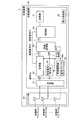
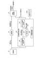
図1は、実施の形態にかかる送信装置および受信装置を備えた無線型被検体内情報取得システムの全体構成を示す模式図である。図1において、被検体内情報取得システムは、被検体1の体内に導入され、体腔内画像を撮像して受信装置3に対して画像信号などのデータ送信を行うカプセル型内視鏡2と、無線受信機能を有する受信装置3とを備える。また、被検体内情報取得システムは、受信装置3が受信した無線信号に基づいて体腔内画像を表示する表示装置4と、受信装置3と表示装置4との間のデータ受け渡しを行うための携帯型記録媒体5とを備える。受信装置3は、アンテナ群3aと、アンテナ群3aによって受信された無線信号の処理などを行う外部装置3bとを備える。(Embodiment 1)
FIG. 1 is a schematic diagram illustrating an overall configuration of a wireless in-vivo information acquiring system including a transmitting device and a receiving device according to an embodiment. In FIG. 1, an in-subject information acquisition system is introduced into the body of a
表示装置4は、カプセル型内視鏡2によって撮像された体腔内画像を表示および処理するためのものであり、携帯型記録媒体5によって得られるデータに基づいて画像表示および画像処理を行うワークステーション等を有する。表示装置4は、CRTディスプレイ、液晶ディスプレイなどによって直接画像を表示する構成としてもよいし、プリンタなどのように、他の媒体に画像を出力する構成としてもよい。 The
携帯型記録媒体5は、外部装置3bおよび表示装置4に対して着脱可能であって、両者に対する挿着時に情報の出力または記録が可能な構造を有する。具体的には、携帯型記録媒体5は、カプセル型内視鏡2が被検体1の体腔内を移動している間は外部装置3bに挿着されてカプセル型内視鏡2から送信されるデータを記録する。そして、カプセル型内視鏡2が被検体1から排出された後、つまり、被検体1の内部の撮像が終った後には、外部装置3bから取り出されて表示装置4に挿着され、表示装置4によって記録したデータが読み出される構成を有する。たとえば、外部装置3bと表示装置4との間のデータの受け渡しをコンパクトフラッシュ(登録商標)メモリ等の携帯型記録媒体5によって行うことで、外部装置3bと表示装置4との間が有線接続された場合と異なり、被検体1が体腔内の撮影中に自由に動作することが可能となる。なお、ここでは、外部装置3bと表示装置4との間のデータの受け渡しに携帯型記録媒体5を使用したが、これに限らず、たとえば、外部装置3bに内臓型の他の記録装置、たとえばハードディスクを用い、表示装置4との間のデータの受け渡しのために、双方を有線または無線接続するように構成してもよい。 The
つぎに、カプセル型内視鏡2および受信装置3について説明する。本実施の形態1において、カプセル型内視鏡2は、特許請求の範囲における送信装置および被検体内導入装置として機能するためのものであり、被検体1内部に導入されることによって被検体内情報である画像情報を取得するとともに、受信装置3に対して無線信号を送信する機能を有する。 Next, the
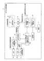
まず、受信装置3について説明する。図2は、受信装置3の全体構成を示す模式的なブロック図である。図1および図2に示すように、受信装置3は、カプセル型内視鏡2から送信される無線信号を受信するための受信用アンテナA1〜Anを有するアンテナ群3aと、受信アンテナA1〜Anを介して受信された無線信号に対して所定の処理を行う外部装置3bとを備えた構成を有する。 First, the receiving
受信アンテナA1〜Anは、カプセル型内視鏡2から送信された無線信号を受信するためのものである。具体的には、受信アンテナA1〜Anは、たとえば、ループアンテナと、ループアンテナを被検体1の表面上に固定するための固着手段とを備えた構成を有する。なお、本実施の形態1において無線信号送信源たるカプセル型内視鏡2は、被検体1内に導入されるとともに被検体1内部を移動しつつ無線信号の送信を行うことから、受信アンテナA1〜Anは、外部装置3bの制御に基づいて、カプセル型内視鏡2の位置に応じて無線信号の受信条件が最も優れたもの、たとえば受信強度が最大となるものが選択され、選択された受信アンテナAを介して無線信号の受信が行われる構成を有する。 The receiving antennas A1 to An are for receiving radio signals transmitted from the
外部装置3aは、受信アンテナA1〜Anのいずれかを介して受信された無線信号に対して、所定の受信処理を行うためのものである。外部装置3bは、図2に示すように、受信部31、変換部33、同期信号検出部34、画像処理部35、制御部36、記憶部37および電力供給部38を備える。受信部31は、無線信号の受信の際に使用するアンテナAを切り替え、切り替えたアンテナAを介して受信された無線信号に対して復調、アナログ/デジタル変換等の受信処理を行い、信号Saを出力する。変換部33は、受信部31から出力された信号Saを画像処理部35が処理可能である信号形式の画像信号Slに変換する。たとえば、変換部33は、信号Saがシリアル形式である場合、パラレル形式に変換した画像信号Slを出力する。同期信号検出部34は、信号Saの中から各種同期信号を検出し、画像処理部35における画像処理のタイミングを指示するタイミング信号Stを出力する。画像処理部35は、変換部33から出力された画像信号Slに対して所定の処理を行い1フレームの画像に対応する画像信号Sfを出力する。制御部36は、全体的な制御とともに画像処理部35を介して入力された画像信号Sfの出力制御を行う。同期確保部39は、カプセル型内視鏡2から送信された無線信号に対する処理基準となるクロック信号を出力する基準クロック39aを有する。同期確保部39は、受信部31において受信された無線信号に所定の基準信号成分が含まれている場合には、この基準信号成分に含まれる基準信号を用いて、基準クロック39aのクロック信号の周波数を、カプセル型内視鏡2から送信された無線信号の周波数変動に対応させて変更し、カプセル型内視鏡2から送信された無線信号の周波数と基準クロック39aとの周波数を同期させている。記憶部37は、制御部36の制御に基づき画像信号Sfを記憶する。記憶部37には、カプセル型内視鏡2によって撮像された各画像が記憶される。また、電力供給部38は、上記の各構成要素に対して駆動電力を供給する。なお、外部装置3aでは、受信用アンテナAを介して受信された無線信号の強度を検出し、制御部36が、無線信号の受信の際に使用するアンテナAを、受信強度が最大となる受信用アンテナAに切り替えるよう受信部31に指示する。 The
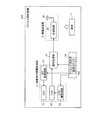
つぎに、カプセル型内視鏡2について説明する。図3は、カプセル型内視鏡2の模式的な構成を示すブロック図である。図3に示すように、カプセル型内視鏡2は、信号処理部12における処理対象である被検体内情報を取得するための被検体内情報取得部11と、取得された被検体内情報を受信装置3に対して無線送信するための無線送信部15とを備える。カプセル型内視鏡2は、被検体内情報取得部11から出力された被検体内情報(この被検体内情報は、本実施の形態1では、CCD信号Cとして説明する。)に対して所定の処理を行い、画像信号Sを出力する信号処理部12を備える。 Next, the
カプセル型内視鏡2は、このカプセル型内視鏡2における同期モードに対応して選択した周波数の基準信号成分Dを生成、出力する基準信号成分出力部13を備える。基準信号成分Dとは、受信装置3の基準クロック39aをカプセル型内視鏡2から送信された無線信号に同期させるために用いられるものであり、異なる信号レベルを含む基準信号を少なくとも含むものである。 The
カプセル型内視鏡2は、基準信号成分出力部13から基準信号成分Dが出力された場合、信号処理部12から出力された画像信号Sに基準信号成分Dを挿入して無線送信部15に出力する挿入部14を備える。挿入部14は、画像信号Sにおける所定の先頭期間または信号成分が存在しない水平ブランキング期間に、基準信号成分出力部13から出力された基準信号成分Dを挿入し、出力する。なお、挿入部14は、基準信号成分Dを挿入するほか、所定の信号成分に基準信号成分Dを重畳させる機能を有する場合もある。 When the reference signal component D is output from the reference signal
また、カプセル型内視鏡2は、上記の各構成要素の駆動タイミングを同期させるためのタイミング発生部16を備える。タイミング発生部16は、たとえば、x〔MHz〕の周波数であるクロック信号を出力する基準クロック16aを有し、この基準クロック16aから出力されるクロック信号を用いて、各構成要素の駆動タイミングを制御している。 Moreover, the
また、カプセル型内視鏡2は、各構成要素の駆動電力を供給するための電池17を備えるとともに、カプセル型内視鏡2における同期モード、すなわち、基準信号成分の挿入の有無と挿入する基準信号成分に含まれる基準信号の周波数とを指示する指示情報を記憶する記憶部22を備える。記憶部22には、このカプセル型内視鏡2の用途、型式、製品番号等の識別情報が記憶されており、このような識別情報が指示情報として機能する。 In addition, the
被検体内情報取得部11は、カプセル型内視鏡2が被検体1の内部に導入された際に被検体内情報を取得するためのものである。本実施の形態1では、被検体内情報として被検体内画像を取得するものとし、被検体内情報取得部11は、画像取得を行うための撮像機能を備えた構成を有する。具体的には、被検体内情報取得部11は、照明部として機能するLED18と、LED18の駆動を制御するLED駆動回路19と、LED18によって照明された領域の少なくとも一部について撮像する撮像部として機能し画像情報であるCCD信号Cを出力するCCD20と、CCD20の駆動を制御するCCD駆動回路21とを備える。LED駆動回路19およびCCD駆動回路21は、タイミング発生部16から指示されたタイミングにしたがって、LED18およびCCD20の駆動を制御する。なお、本実施の形態1では、撮像部としてCCDを用いることとしたが、かかる構成は必須ではなく、たとえば撮像部をCMOS等によって構成することとしてもよい。 The in-subject
無線送信部15は、挿入部14を介して入力された情報に関して、外部に無線送信するためのものである。具体的には、無線送信部15は、入力された情報に対して必要な変調処理等を行う送信回路25と、送信アンテナ26とを備えた構成を有する。 The
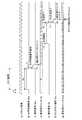
信号処理部12は、CCD20によって取得されたCCD信号Cに対して所定の処理を施すことによって画像信号Sを生成するためのものであり、特許請求の範囲における情報本体出力手段として機能する。また、信号処理部12によって出力される画像信号Sは、特許請求の範囲における情報本体部分として機能する。信号処理部12は、1枚の画像に対応した1フレーム期間(フレーム周期)を構成する画像信号期間TMにおいて、CCD20によって撮像された画像情報の各走査線に対応した走査線成分Seを出力する。画像信号Sは、垂直同期信号を含む先頭の標準同期成分Sdを有する先頭同期期間TSと、水平同期信号をそれぞれ含む各走査線に対応する走査線成分Seと各走査線成分Se間に所定のブランキング期間である水平ブランキング期間Thを設けられた構成を有する画像信号期間TMとを備える。水平ブランキング期間Thには、何ら信号成分が含まれない。ここで、垂直同期信号および水平同期信号は、受信装置3において画像を再構成するために使用される信号であり、垂直同期信号は、垂直方向の同期を取るために用いられ、水平同期信号は、水平方向の同期を取るために用いられる。 The
基準信号成分出力部13は、記憶部22に記憶された指示情報をもとに、このカプセル型内視鏡2における受信装置3に対する同期モードを選択し、選択した同期モードに対応する周波数の基準信号を生成し、生成した基準信号を含む基準信号成分Dをタイミング発生部16が指示するタイミングにしたがって出力するためのものである。基準信号成分出力部13は、同期モード選択部23と基準信号生成部24とを備える。同期モード選択部23は、記憶部22に記憶された指示情報をもとに、このカプセル型内視鏡2における同期モードを選択する。具体的には、同期モード選択部23は、このカプセル型内視鏡2における同期モードに対応する基準信号成分の挿入の有無と、基準信号成分を挿入する場合における基準信号成分に含まれる基準信号の周波数とを選択する。同期モード選択部23は、信号処理部12が出力する画像信号Sの周波数に対応した周波数を基準信号に用いる完全同期モード、被検体内情報取得部11が出力するCCD信号Cの周波数に対応した周波数を基準信号に用いる固定同期モード、基準信号を用いず基準信号成分を挿入しない非同期モードのいずれかを選択する。基準信号生成部24は、同期モード選択部23が選択した同期モードに対応する周波数の基準信号を生成し、生成した基準信号を含む基準信号成分Dを出力する。基準信号生成部24は、同期モード選択部23によって完全同期モードが選択された場合、信号処理部12が出力する画像信号Sの周波数に対応した周波数である完全基準信号を生成し、この完全基準信号を含む完全基準信号成分Dpを出力する。また、基準信号生成部24は、同期モード選択部23によって固定同期モードが選択された場合、被検体内情報取得部11が出力するCCD信号Cの周波数に対応した周波数である固定基準信号を生成し、この固定基準信号を含む固定基準信号成分Dcを出力する。また、基準信号生成部24は、同期モード選択部23によって非同期モードが選択された場合、信号生成を行わない。 The reference signal
ここで、カプセル型内視鏡2における基準クロック16aの周波数をx〔MHz〕とした場合、信号処理部12が出力する画像信号Sの出力周波数は、(x/6)〔MHz〕である。また、CCD20の駆動クロックの周波数は、基準クロックx〔MHz〕を分周した(x/4)〔MHz〕である。タイミング発生部16は、画像信号Sの出力周波数(x/6)〔MHz〕の信号を供給する供給源およびCCD20の駆動クロックの周波数である(x/4)〔MHz〕の信号を供給する供給源を備え、この供給源から出力された信号をもとに、各構成要素の処理タイミングを制御している。 Here, when the frequency of the
また、基準信号生成部24は、完全基準信号として、(x/6)〔MHz〕の(1/2n)の周波数を有する信号を生成、出力する。また、基準信号生成部24は、固定基準信号として、(x/4)〔MHz〕の(1/2n)の周波数を有する信号を生成、出力する。たとえば、基準信号生成部24は、(x/6)〔MHz〕の周波数の信号を分周する完全変更用分周回路と、(x/4)〔MHz〕の周波数の信号を分周する固定変更用分周回路とを備える。基準信号生成部24における各分周回路と各信号の供給源は、それぞれスイッチを介して配置されている。Further, the reference
そして、同期モード選択部23は、完全同期モードを選択した場合には、完全変更用分周回路と(x/6)〔MHz〕の信号の供給源との間のスイッチをオン状態として、基準信号生成部24へ(x/6)〔MHz〕の信号の供給を可能とする。この結果、基準信号生成部24は、完全基準信号を生成、出力することができる。また、同期モード選択部23は、固定同期モードを選択した場合には、固定変更用分周回路と(x/4)〔MHz〕の信号の供給源との間のスイッチをオン状態として、基準信号生成部24へ(x/4)〔MHz〕の信号の供給を可能とする。この結果、基準信号生成部24は、固定基準信号を生成、出力することができる。なお、同期モード選択部23は、非同期モードを選択した場合には、いずれのスイッチに対してもオフ状態を維持させることによって、基準信号生成部24への信号の供給を停止している。この結果、基準信号生成部24は、何ら信号を生成しない。 When the complete synchronization mode is selected, the synchronization
つぎに、図4を参照して、基準信号成分出力部13の処理動作について説明する。図4は、図3に示す基準信号成分出力部13の処理動作を示すフローチャートである。図4に示すように、まず、同期モード選択部23は、記憶部22に記憶された指示情報等を取得し(ステップS102)、取得した指示情報をもとに、完全同期モード、固定同期モード、非同期モードのいずれかの同期モードを選択する(ステップS104)。そして、基準信号生成部24は、同期モード選択部23によって選択された同期モードが完全同期モード、固定同期モード、非同期モードのいずれであるかを判断する(ステップS106)。基準信号生成部24は、同期モード選択部23によって選択された同期モードが完全同期モードであると判断した場合(ステップS106:完全同期モード)、完全基準信号を生成し(ステップS108)、生成した完全基準信号を含む完全基準信号成分Dpをタイミング発生部16から指示される処理タイミングに合わせて挿入部14に出力する(ステップS110)。また、基準信号生成部24は、同期モード選択部23によって選択された同期モードが固定同期モードであると判断した場合(ステップS106:固定同期モード)、固定基準信号を生成し(ステップS112)、生成した固定基準信号を含む固定基準信号成分Dcをタイミング発生部16から指示される処理タイミングに合わせて挿入部14に出力する(ステップS114)。また、基準信号生成部24は、同期モード選択部23によって選択された同期モードが非同期モードであると判断した場合(ステップS106:非同期モード)、基準信号の生成、出力を行わない。 Next, the processing operation of the reference signal
つぎに、完全同期モードについて説明する。たとえば、同期モード選択部23は、記憶部22に記憶された識別情報のうち、カプセル型内視鏡2が撮像期間の短い食道用のものであることを示す情報を取得した場合には、完全同期モードを選択する。 Next, the complete synchronization mode will be described. For example, when the synchronization
ここで、信号処理部12は、1枚の画像に対応した1フレーム期間(フレーム周期)を構成する画像信号期間TMにおいて、CCD20によって撮像された画像情報を出力する。具体的には、図5に示すように、画像信号期間TM中には、走査線の本数に対応した数の画像ライン期間THが設けられ、信号処理部12は、画像ライン期間THのそれぞれに関して画像情報の各走査線に対応した走査線成分Seを生成、出力している。信号処理部12は、水平同期信号を生成し、走査線成分Seの先頭部分に付した状態で出力する。また、互いに隣接する画像ライン期間THの間には、水平ブランキング期間Thが設けられており、信号処理部12から出力される画像信号Sの水平ブランキング期間Thには何ら信号成分が含まれないこととする。また、1フレーム期間の先頭部分において、受信装置側で1枚の画像に対する処理準備期間に対応する先頭同期期間が設けられており、信号処理部12は、先頭同期期間TS内において、垂直同期信号を生成し、この垂直同期信号を含む標準同期成分Sdを出力する。画像信号Sは、標準同期成分Sdと、各走査線成分Seとを含み、各走査線成分Seの間に水平ブランキング期間Thを含む構成である。 Here, the
同期モード選択部23によって完全同期モードが選択された場合、基準信号生成部24は、完全基準信号を生成し、完全基準信号成分Dpを出力する。図5に示すように、基準信号成分出力部13は、タイミング発生部16の制御のもと、先頭同期期間TSの前半期間および水平ブランキング期間Thに対応して、完全基準信号成分Dpを出力する。また、信号処理部12は、上述したように、タイミング発生部16の制御のもと、先頭同期期間TSにおいて標準同期成分Sdを出力し、各画像ライン期間THにおいて、走査線成分Seをそれぞれ出力する。このように、タイミング発生部16は、同期モード選択部23によって完全同期モードが選択された場合、基準信号生成部24における完全基準信号成分Dpの出力タイミングを、先頭同期期間TSの前半期間および水平ブランキング期間Th時に対応させたものとしている。 When the complete synchronization mode is selected by the synchronization
この結果、図6に示すように、挿入部14から出力される信号の構成は、先頭同期期間TSの前半期間には、完全基準信号成分Dpが挿入され、また、走査線成分Se間の水平ブランキング期間Thには完全基準信号成分Dpが挿入される。すなわち、カプセル型内視鏡2は、無線送信部15から、先頭同期期間TSおよび水平ブランキング期間Thに完全基準信号成分Dpが挿入された状態で、画像情報を含む無線信号を受信装置3に送信することとなる。 As a result, as shown in FIG. 6, in the configuration of the signal output from the
受信装置3側では、受信した無線信号のうち、先頭同期期間TSおよび水平ブランキング期間Thに挿入された完全基準信号成分Dpから完全基準信号を抽出する。そして、受信装置3は、抽出した完全基準信号と受信装置3側の基準クロック39aから出力されたクロック信号を分周した信号との間で位相比較を行うことによって、受信装置3側の基準クロック39aから出力されたクロック信号を分周した信号の周波数と、カプセル型内視鏡2から送信された無線信号との同期を確保する。その後は、受信装置3は、水平ブランキング期間Thに対応する期間ごとに、水平ブランキング期間Thに挿入された完全基準信号成分Dpの完全基準信号を用いて、受信装置3側とカプセル型内視鏡2から送信された無線信号との同期を確保する処理を繰り返し、基準クロック39aの周波数を、カプセル型内視鏡2から送信された無線信号の変動に対応させて合わせ込みを行っていく。したがって、受信装置3は、カプセル型内視鏡2から送信された無線信号の周波数変動に合わせて、基準クロック39aの周波数を、カプセル型内視鏡2から送信された無線信号の周波数に完全に同期させることができるため、カプセル型内視鏡2から送信された無線信号のうち、垂直同期信号、水平同期信号を正確に検出することができなかった場合であっても、カプセル型内視鏡2が撮像した画像を正確に取得することができる On the receiving
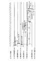
つぎに、固定同期モードについて説明する。たとえば、同期モード選択部23は、記憶部22に記憶された識別情報のうち、カプセル型内視鏡2が撮像期間の短い食道用のものであり、CCD20が撮像する画像情報にノイズが混入する型式であることを示す情報を取得した場合には、固定同期モードを選択する。この場合、基準信号生成部24は、CCD信号Cの出力周波数(x/4)〔MHz〕に対応した固定基準信号を生成し、この固定基準信号を含む固定基準信号成分Dcを出力する。図7に示すように、基準信号成分出力部13は、先頭同期期間TSの前半期間および水平ブランキング期間Thに対応して、固定基準信号を含む固定基準信号成分Dcを出力する。この場合、タイミング発生部16は、同期モード選択部23によって固定同期モードが選択された場合、基準信号生成部24における固定基準信号成分Dcの出力タイミングを、先頭同期期間TSの前半期間および水平ブランキング期間Th時に対応させたものとしている。 Next, the fixed synchronization mode will be described. For example, in the synchronization
この結果、図8に示すように、挿入部14から出力される信号の構成は、先頭同期期間TSの前半部分には、固定基準信号成分Dcが挿入され、また、走査線成分Se間の水平ブランキング期間Thには固定基準信号成分Dcが挿入される。すなわち、カプセル型内視鏡2は、無線送信部15から、先頭同期期間TSの前半期間および水平ブランキング期間Thに固定基準信号が挿入された状態で、画像情報を含む無線信号を受信装置3に送信することとなる。 As a result, as shown in FIG. 8, the configuration of the signal output from the
受信装置3側では、受信した無線信号のうち、先頭同期期間TSにおける固定基準信号成分Dcから固定基準信号を抽出し、この固定基準信号を用いて、受信装置3の基準クロック39aにおけるクロック信号の周波数を、無線信号の周波数変動に合わせて合わせこむ。そして、先頭同期間TSにおける信号成分から垂直同期信号を抽出して、1フレームの画像信号の先頭部分を検出する。その後、制御部36は、水平ブランキング期間Thに挿入された固定基準信号成分Dcの固定基準信号を用いて、基準クロック36のクロック信号の周波数を、カプセル型内視鏡2から送信された無線信号の周波数変動に対応させて変更を繰り返し、無線信号の周波数と基準クロック39aのクロック信号の周波数の合わせ込みを維持する。この結果、受信装置3は、水平ブランキング期間Thに挿入された固定基準信号を用いることによって、各走査線の先頭部分を正確に検出することができ、各走査線に対応する画像情報の先頭部分を検出することができるため、1枚の画像全体に対応する画像情報を正確に取得することができる。 On the receiving
つぎに、非同期モードについて説明する。同期モード選択部23は、記憶部22に記憶された識別情報のうち、カプセル型内視鏡2が撮像期間の長い小腸用のものであることを示す情報を取得した場合には、基準信号成分Dの挿入を選択せず、基準信号生成部24は、先頭同期期間および水平ブランキング期間に挿入する基準信号成分の生成、出力を行わない。この結果、図9に示すように、挿入部14から出力される信号の構成は、信号処理部12から出力された先頭同期期間TSにおける標準同期成分Sdおよび画像ライン期間THにおける走査線成分Seとなる。この場合、受信装置3は、受信した無線信号から垂直同期信号および水平同期信号を抽出し、垂直同期信号および水平同期信号を用いて受信した無線信号に含まれる画像信号を処理する。カプセル型内視鏡2が非同期モードを用いて無線信号を送信する場合、水平ブランキング期間Th間に挿入する基準信号の生成を行う必要がない。このため、非同期モードを選択した場合、完全同期モードおよび固定同期モードを選択した場合と比較し、カプセル型内視鏡2における消費電力の低減を可能にする。特に、非同期モードは、カプセル型内視鏡2が長時間の撮像および画像情報の送信を行う場合に適している。 Next, the asynchronous mode will be described. When the synchronization
このように、本実施の形態1にかかるカプセル型内視鏡2は、非同期モードのほかに、受信側から送信された無線信号の周波数変動に対応させた受信側の基準クロックの周波数の変更を可能とする完全同期モードおよび固定同期モードを含む複数の同期モードを選択可能とすることによって、カプセル型内視鏡2の用途に対応させて、適切な同期モードを柔軟に選択することができる。また、本実施の形態1にかかるカプセル型内視鏡2では、用途に合わせて、完全同期モードまたは固定同期モードを選択し、完全基準信号または固定基準信号を含む基準信号成分Dを挿入した信号を送信する。このような基準信号を用いることによって、受信装置3において、基準クロック39aの周波数をカプセル型内視鏡2から送信された送信信号の周波数変動に対応させて変更し、カプセル型内視鏡2から送信された無線信号の周波数と受信装置の基準クロックの周波数とを同期させることができ、受信した無線信号を周波数の変動によらず正確に処理することができる。このため、受信装置3は、垂直同期信号、水平同期信号を正確に検出することができない場合であっても、画像情報を正確に処理することができる。この結果、受信装置3は、カプセル型内視鏡2が取得した体腔内の画像を正確にユーザに提供でき、ユーザによる正確な診察を支援することが可能になる。 As described above, the
なお、同期モード選択部23は、記憶部22に記憶された指示情報等をもとに、カプセル型内視鏡2における同期モードを所定の時間ごとに変更してもよい。たとえば、同期モード選択部23は、撮像時間が短い食道部に対応する期間は、完全同期モードまたは固定同期モードを選択し、撮像時間が長い小腸部に対応する期間は、非同期モードを選択する。このように、カプセル型内視鏡2の動作期間の間、撮像部に最も適する同期モードを変更してもよい。また、本実施の形態1では、同期モード選択部23は、記憶部22に記憶された指示情報をもとに同期モードを選択する場合について説明したが、これに限らない。たとえば、カプセル型内視鏡2が受信機能を備えている場合には、同期モード選択部23は、外部から送信された指示情報をもとに、同期モードを選択してもよい。 The synchronization
(実施の形態2)
つぎに、実施の形態2について説明する。実施の形態2では、非同期モードを用いてカプセル型内視鏡から送信された無線信号を処理する受信装置において、水平同期信号を検出できない走査線に対して、所定の再生信号を生成し、生成した再生信号をもとに画像信号を処理する。(Embodiment 2)
Next, a second embodiment will be described. In the second embodiment, a predetermined reproduction signal is generated and generated for a scanning line in which a horizontal synchronization signal cannot be detected in a receiving apparatus that processes a radio signal transmitted from a capsule endoscope using an asynchronous mode. The image signal is processed based on the reproduced signal.
図10は、実施の形態2におけるカプセル型内視鏡の模式的な構成を例示するブロック図である。実施の形態2におけるカプセル型内視鏡は、たとえば、図10に示すカプセル型内視鏡202のように、図3に示すカプセル型内視鏡2と比較し、基準信号成分出力部13、挿入部14、記憶部22を削除した構成を有し、前述した非同期モードを用いて無線信号を送信する。このため、カプセル型内視鏡202からは、図9に示すように、垂直同期信号を含む先頭同期期間TSと、水平同期信号を含む走査線成分Seが送信される画像ライン期間THおよび水平ブランキング期間Thが交互に繰り返される画像信号期間TMとを有する構成を備えた画像信号Sに対応する無線信号が送信される。 FIG. 10 is a block diagram illustrating a schematic configuration of the capsule endoscope according to the second embodiment. The capsule endoscope according to the second embodiment is, for example, like the
つぎに、実施の形態2にかかる受信装置について説明する。図11は、実施の形態2にかかる受信装置の模式的な構成を示すブロック図である。図11に示すように、実施の形態3における受信装置203は、図2に示す受信装置3と比較し、同期確保部39に代えて、基準クロック39aと同様の機能を有する基準クロック239aを有する。また、受信装置203は、同期信号検出部34に代えて、同期信号検出部234を有する外部装置203bを備える。同期信号検出部234は、基準クロック239aから出力されたクロック信号をもとに、受信部31から出力された信号Saの中から垂直同期信号および水平同期信号を検出し、垂直同期信号および水平同期信号に基づいて画像処理部35における処理動作のタイミングを指示するタイミング信号を画像処理部35に出力する。また、同期信号検出部234は、水平同期信号を検出できなかった場合、この走査線に対して再生信号を生成し、生成した再生信号に基づいてタイミング信号Stを画像処理部35に出力する。画像処理部35は、同期信号検出部234から出力されたタイミング信号をもとに、画像信号Slの入力タイミングとの同期を取って、画像信号Slの処理を開始する。具体的には、画像処理部35は、同期信号検出部234から出力されたタイミング信号にしたがって、1フレームの先頭画素および各走査線の先頭画素に対応する画素信号を区別し、画素信号ごとに所定の処理を行う。なお、受信装置203は、非同期モードを採用している。 Next, a receiving apparatus according to the second embodiment will be described. FIG. 11 is a block diagram of a schematic configuration of the receiving apparatus according to the second embodiment. As shown in FIG. 11, the receiving
つぎに、図11に示す外部装置203bの同期信号検出部234について説明する。図12は、図11に示す外部装置203bの要部構成を示すブロック図である。図12では、同期信号検出部234を構成する構成要素のうち、特に、水平同期信号の検出および水平同期信号に基づくタイミング信号Stの生成に関する構成要素について示す。 Next, the synchronization
図12に示すように、同期信号検出部234は、水平同期信号検出部236と、再生部237と、タイミング信号生成部238と、同期信号検出部234の各構成要素の処理動作を制御する同期制御部239を備える。 As shown in FIG. 12, the synchronization
水平同期信号検出部236は、受信部31から出力された信号Saのうち、各走査線に対応する水平同期信号を検出し、水平同期信号を検出した場合には、水平同期信号を検出した旨を示し、この水平同期信号が付された走査線成分の先頭を示す検出信号Shをタイミング信号生成部238に出力する。また、水平同期信号検出部236は、信号Saのうち、水平同期信号を形成する信号のうち予め設定された所定部分以上を検出した場合、水平同期信号の信号全体を検出できない場合であっても、水平同期信号を検出したものとして検出信号Shを出力する。 The horizontal synchronization
再生部237は、水平同期信号検出部236が水平同期信号を検出できなかった場合、水平同期信号検出部236が前回検出した水平同期信号をもとに、この走査線成分に対して再生信号Shdを生成し、タイミング信号生成部238に出力する。この再生部237は、水平同期信号検出部236が前回の検出信号を生成してから次の走査線成分に対して同期信号を検出するまでの期間に水平同期信号を検出しない場合、再生信号Shdを生成する。この再生信号Shdは、水平同期信号が検出されなかった走査線成分の先頭を示すものである。再生部237は、カプセル型内視鏡202から一定の画像ライン期間THおよび一定の水平ブランキング期間Thにしたがって無線信号が送信され、受信装置203が画像ライン期間THおよび水平ブランキング期間Thにしたがって無線信号を受信すると想定して、再生信号Shdを生成する。この想定のもと、再生部237は、水平同期信号検出部236が前回の検出信号Shを出力した時から次に検出信号Shを出力すると想定された期間経過時に、水平同期信号検出部236が検出信号Shを出力しない場合、再生信号Shdを生成、出力する。 When the horizontal synchronization
タイミング信号生成部238は、水平同期信号検出部236から出力された検出信号Shあるいは再生部237から出力された再生信号Shdをもとに、画像処理部35への画像信号Slにおける走査線成分の入力タイミングに対応させて、画像信号Slにおける走査線成分の処理開始タイミングを指示するタイミング信号Stを画像処理部35に出力する。タイミング信号生成部238は、画像信号Slのうち、1画素を構成する画素信号ごとにタイミング信号Stを出力する。また、タイミング信号生成部238は、再生信号Shdに基づくタイミング信号Stの最初の出力を、検出信号Shに基づくタイミング信号Stの最初の出力よりも、再生部237における再生信号の生成期間分早めている。この結果、タイミング信号生成部238は、検出信号Shを用いた場合および再生信号Shdを用いた場合のいずれであっても、画像処理部35が画像信号Slの先頭に位置する画素信号を処理するタイミングを正確に指示することができる。 Based on the detection signal Sh output from the horizontal synchronization
つぎに、図13を参照して、同期信号検出部234が水平同期信号に基づくタイミング信号Stを出力するまでの処理動作について説明する。図13に示すように、同期信号検出部234では、まず、同期制御部239が、水平同期信号検出部236が信号Saから水平同期信号を抽出できたか否かを判断する(ステップS202)。 Next, with reference to FIG. 13, the processing operation until the synchronization
同期制御部239において水平同期信号検出部236が水平同期信号を抽出できたと判断された場合(ステップS202:Yes)、水平同期信号検出部236は、抽出した水平同期信号の信号幅が所定幅以上であるか否か、すなわち、抽出した水平同期信号の信号幅が採用可能幅以上であるか否かを判断する(ステップS204)。水平同期信号検出部236は、抽出した水平同期信号の信号幅が採用可能幅以上であると判断した場合(ステップS204:Yes)、抽出した水平同期信号を採用し(ステップS206)、検出信号Shを生成し、タイミング信号生成部238に出力する(ステップS208)。一方、水平同期信号検出部236は、抽出した水平同期信号の信号幅が採用可能幅以上でないと判断した場合(ステップS204:No)、この水平同期信号を採用せず(ステップS210)、ステップS212に進む。この場合、水平同期信号検出部236は、検出信号Shの生成、出力を行わない。 When the
同期制御部239において水平同期信号検出部236が水平同期信号を抽出できないと判断された場合(ステップS202:No)、または、水平同期信号検出部236が抽出した水平同期信号を採用せず(ステップS210)検出信号Shを生成しなかった場合、同期制御部239は、再生部237に再生信号Shdの生成を指示し、再生部237は、再生信号Shdを生成し、タイミング信号生成部238に出力する(ステップS212)。 When the
タイミング信号生成部238は、受信した検出信号Shまたは再生信号Shdを用いてタイミング信号Stを生成する(ステップS214)。そして、同期制御部239は、タイミング信号生成部238が検出信号Shまたは再生信号Shdのいずれを用いてタイミング信号Stを生成したかを判断する(ステップS216)。 The timing
同期制御部239は、タイミング信号生成部238が検出信号Shを用いてタイミング信号Stを生成したと判断した場合(ステップS216:検出信号)、タイミング信号生成部238に対して、所定の基準タイミングでタイミング信号Stを出力させる(ステップS218)。この基準タイミングは、再生部237における再生信号Shdの生成期間を考慮しないものである。タイミング信号生成部238は、この基準タイミングにしたがって、検出信号Shが水平同期信号検出部237から入力されてから所定の基準待機期間経過後にタイミング信号Stを出力し、その後、一定の出力タイミングでタイミン信号Stを出力する。 When the
一方、同期制御部239は、タイミング信号生成部238が再生信号Shdを用いてタイミング信号Stを生成したと判断した場合(ステップS216:再生信号)、タイミング信号生成部237に対して、再生信号用タイミングでタイミング信号Stを出力させる。再生信号用タイミングとは、再生部237における再生信号の生成期間を考慮したものである。タイミング信号生成部238は、この再生信号用タイミングにしたがって、再生信号Shdが再生部238から出力されてから所定の再生用待機期間の経過後にタイミング信号Stを出力し、その後、一定の出力タイミングでタイミング信号Stを出力する(ステップS220)。再生用待機期間とは、再生信号Shdが入力されてから再生信号Shdに基づいて生成されたタイミング信号Stを出力するまでの期間を、検出信号Shが入力されてから検出信号Shに基づいて生成されたタイミング信号Stを出力する間での期間と比較し、再生部237における再生信号の生成期間に対応する期間分短縮したものである。このように、タイミング信号出力部238は、検出信号Shまたは再生信号Shdのいずれかに対応させて、出力タイミングを変化してタイミング信号Stを出力する。 On the other hand, when the
つぎに、図13で説明した各処理について、図14以降に示すタイミングチャートを参照して説明する。まず、水平同期信号検出部236が検出信号Shを出力するまでの信号処理について説明する。図14は、水平同期信号検出部236が水平同期信号を検出し、検出信号Shを出力するまでの各信号および各カウンタにおけるタイミングチャートを示す図である。図14において、(a)は、基準クロック239aから同期制御部239に入力されるクロック信号に対応し、6クロック分の信号(6C)が信号Saの1画素当たりの画素信号の信号幅に対応する。(b)は、水平同期信号検出部236が抽出した水平同期信号Sh0に対応し、(c)は、水平同期信号検出部236が水平同期信号Sh0を検知した場合に同期制御部239に出力する検知信号Shaに対応し、(d)は、同期制御部239が有する検出信号生成用の検出用カウンタChのカウント値に対応し、(e)は、水平同期信号検出部236が生成する検出信号Shに対応し、(f)は、同期制御部239が有する再生用カウンタChdに対するカウンタリセット信号Scrに対応し、(g)は、再生用カウンタChdのカウント値に対応する。 Next, each process described in FIG. 13 will be described with reference to timing charts shown in FIG. First, signal processing until the horizontal
図14において、(b)に示すように、水平同期信号検出部236は、たとえば6C相当の水平同期信号Sh0(ここで、水平同期信号Sh0の信号幅全体は、6C幅に相当するとして説明する。)を抽出した場合、矢印Y1に示すように、水平同期信号Sh0の立下り部分を検知し、(c)に示すように、水平同期信号Sh0の立下り部の次のクロックで検知信号Shaを出力する。そして、矢印Y2に示すように、この検知信号Shaを受け、同期制御部239は、検出用カウンタChのカウント値を「0」にリセットし、クロック信号にしたがってカウントを開始する。水平同期信号検出部236は、同期制御部239の制御のもと、矢印Y3に示すように、検出用カウンタChのカウント値が「6」の際に検出信号Shの生成、出力を開始し、矢印Y4に示すように、カウント値が「11」の際に検出信号Shの生成、出力を停止する。すなわち、水平同期信号生成部236は、水平同期信号の立下り部を検知してから、1画素に対応する6C後に、6C分の検出信号Shを生成し、出力する。その後、水平同期信号検出部236は、矢印Y5に示すように、検出信号Sh生成後、すなわち、検出用カウンタChのカウント値「12」の際に、カウンタリセット信号Scrを同期制御部239に出力する。同期制御部239は、矢印Y6に示すように、カウンタリセット信号Scrを受け、カウントを行っていた再生用カウンタChdのカウント値「20591」を「0」に戻して、クロック信号にしたがってカウントを開始する。カウント値「0」から「20591」までの幅は、水平同期信号を含んだ1本の走査線分の画像信号幅に相当する。このため、同期制御部239は、検出信号Shの出力終了によって、この走査線における水平同期信号の検出が正常に検出できたものとして、再生用カウンタChdのカウント値をリセットし、次の走査線における水平同期信号の検出の可否を判断するため、再生用カウンタChdのカウントを再度開始する。 In FIG. 14, as shown in FIG. 14B, the horizontal
ここで、水平同期信号検出部236は、抽出した水平同期信号の信号幅が採用可能幅以上であれば、抽出した水平同期信号を採用して検出信号Shを生成する。たとえば、水平同期信号検出部236は、抽出した水平同期信号Sh0が、図15(1)の(a)に示すように、水平同期信号の全体の幅に相当する6C幅のうち、3C幅以上であれば、同期信号検出部234は、画像処理部35に対するタイミング信号Stの正確な生成、出力が可能である。このため、水平同期信号Sh0の信号幅が3C幅以上である場合、水平同期信号検出部236は、検知信号Shaを出力し、検出用カウンタChをリセットおよびカウントスタートさせる。この結果、水平同期信号検出部236が、検出信号Shを生成、出力する。しかしながら、図15(2)の(e)に示すように、水平同期信号検出部236は、抽出した水平同期信号Sh0が、水平同期信号の全体の幅に相当する6C幅のうち、2C幅以下である場合には、同期信号検出部234は、画像処理部35に対するタイミング信号Stの正確な生成、出力が困難となる。このため、水平同期信号Sh0の信号幅が2C幅以下である場合には、水平同期信号検出部236は、検知信号Shaを出力せず、検出信号Shの生成、出力を行わない。このように、同期信号検出部234では、正確なタイミング信号Stの生成、出力が可能である信号幅の水平同期信号Sh0を抽出できなかった場合には、検出信号Shではなく、再生部237によって生成、出力された再生信号Shdを用いて、タイミング信号Stを生成する。 Here, if the signal width of the extracted horizontal synchronization signal is equal to or larger than the employable width, the horizontal synchronization
つぎに、図16に示すタイミングチャートを参照して、再生部237において再生信号Shdが生成、出力されるまでの信号処理について説明する。図16における(a)〜(f)に示す各タイミングチャートは、図14において説明したクロック信号、水平同期信号Sh0、検知信号Sha、検出用カウンタChのカウント値、検出信号Sh、再生用カウンタChdのカウント値に対応する。また、図16における(g)は、再生部237において生成される再生信号Shdに対応し、(h)は、図14において説明したカウンタリセット信号Scrに対応する。 Next, with reference to a timing chart shown in FIG. 16, signal processing until the reproduction signal Shd is generated and output in the
図16(b)において、矢印Y7に示すように、水平同期信号Sh0が水平同期信号検出部236において検出されなかった場合、(c)および矢印Y8に示すように、検知信号Shaが生成されず、検出用カウンタChのカウント値がリセットされない。この結果、(e)と矢印Y9に示すように、検出信号Shが水平同期信号検出部236から出力されない。この場合、図16(e)において、同期制御部239は、矢印Y11に示すように、再生用カウンタChdのカウント値「20591」である場合であっても、再生用カウンタChdに対するカウンタリセット信号Scrに基づくカウント値のリセットおよびカウントスタートの指示がないと判断した場合、水平同期信号検出部236における水平同期信号の検出がなされなかったものと判断し、再生部237に対して再生信号Shdの生成を指示する。再生用カウンタChdのカウント値「20591」である場合とは、1本の走査線分の画像信号幅に相当する期間が経過した場合に相当する。カウント値「20591」時では、正常に水平同期信号Sh0を検出できた場合、図14に示すように、検出信号Shの生成、出力の完了およびカウンタリセット信号Scrの出力が完了しているためである。このため、同期制御部239は、再生用カウンタChdのカウント値「20591」時にカウンタリセット信号Scrを受信しない場合には、この期間までに、水平同期信号検出部236が、水平同期信号Sh0を検出できず、検出信号Shが出力しなかった場合であると判断する。 In FIG. 16B, when the horizontal synchronization signal Sh0 is not detected by the horizontal
この場合、再生部237は、同期制御部239の制御のもと、矢印Y12に示すように、再生用カウンタChdのカウント値「20591」を含む6C幅分後のカウント値「20597」時に再生信号Shdの生成、出力を開始し、矢印Y13に示すように、カウント値が「20602」の際に再生信号Shdの生成、出力を停止する。そして、再生部267は、矢印Y14に示すように、再生信号Shdの生成終了後にカウンタリセット信号Scrを同期制御部239に出力する。同期制御部239は、このカウンタリセット信号を受信し、矢印Y15に示すように、再生用カウンタChdのカウント値を「0」にリセットした後、再生用カウンタChdにカウントを開始させる。 In this case, the
ここで、図16に示すように、再生部237は、水平同期信号検出部236から検出信号Shが出力される場合と比較し、12C幅分、すなわち、2画素分の信号幅に対応する分、遅いタイミングで再生信号Shdを生成、出力している。 Here, as shown in FIG. 16, the reproducing
この遅いタイミングでの再生信号Shdの生成、出力を吸収する必要がある。このため、再生部237は、再生信号Shdを生成、出力した走査線成分の次の走査線成分に対して再生信号Shd2を生成、出力する場合には、2画素分の信号幅に対応する期間分早いタイミングで再生信号を生成、出力する。具体的には、図17(f)(g2)の矢印Y21に示すように、再生部237は、再生信号Shdを生成、出力した走査線の次の走査線に対応させて、最初に生成した再生信号Shdの生成タイミングより12C幅分早い、カウント値「20584」の際に再生信号Shd2の生成、出力を開始する。このように、再生部237は、12C幅分、すなわち、2画素分の信号幅に対応する期間分早いタイミングで再生信号Shd2を生成する。そして、再生部237は、矢印Y22に示すように、カウント値「20584」から6C幅分後のカウント値「20590」の際に再生信号Shd2の生成、出力を停止する。その後、再生部267は、矢印Y23に示すように、再生信号Shd2の生成終了後にカウンタリセット信号Scrを同期制御部239に出力する。同期制御部239は、このカウンタリセット信号Scrを受信し、矢印Y24に示すように、再生用カウンタChdのカウント値を「0」にリセットした後、再生用カウンタChdにカウントを開始させる。 It is necessary to absorb the generation and output of the reproduction signal Shd at this late timing. For this reason, when the reproducing
つぎに、タイミング信号生成部238におけるタイミング信号Stの生成に対する信号処理について図18に示すタイミングチャートを参照して説明する。図18(1)は、タイミング信号生成部238が検出信号Shを用いてタイミング信号Stを生成した場合に対応し、(a)は、検出信号Shに対応し、(b)は、タイミング信号生成部238が有するタイミングカウンタCtへのカウント値のリセットおよびカウントスタートを指示するリセット信号Strに対応し、(c)は、タイミングカウンタCtのカウント値に対応し、(d)は、タイミング信号生成部238が生成するタイミング信号Stに対応し、(e)は、変換部33から出力される画像信号Slの各走査線におけるデータ信号に対応する。また、図18(2)は、タイミング信号生成部238が再生信号Shdを用いてタイミング信号Stを生成した場合に対応し、(f)は、再生信号Shdに対応し、(g)は、リセット信号Strに対応し、(h)は、タイミングカウンタCtのカウント値に対応し、(i)は、タイミング信号Stに対応し、(j)は、データ信号に対応する。なお、図18では、各信号および各カウンタは、(A)に示すクロック信号に基づいて処理される。また、タイミングカウンタCtは、カウント値「0」から開始し、カウント値「5」まで進むと、自動的に「0」値にリセットされ、カウントを進める。変換部33に入力される信号Saのうち各画素情報を示すデータ信号(e),(j)に示すように、1画素あたり、6C分の信号幅を有しており、タイミングカウンタCtは、1画素あたりの信号幅に対応してカウントを行っている。 Next, signal processing for generation of the timing signal St in the timing
まず、図18(1)を参照し、タイミング信号生成部238が検出信号Shを用いてタイミング信号Stを生成した場合について説明する。図18(a)において、タイミング信号生成部238は、検出信号Shの受信を検出した場合、矢印Y31に示すように、(b)に示すリセット信号StrをタイミングカウンタCtに出力する。この結果、矢印Y32に示すように、(c)に示すタイミングカウンタCtのカウント値は、「0」にリセットされた後カウントを進める。そして、タイミング信号生成部238は、矢印Y33および(d)に示すように、タイミングカウンタCtのカウント値「1」の間に、リセット信号Strを生成する。この場合、そして、矢印Y34に示すように、次にタイミングカウンタCtのカウント値「1」となる間に、すなわち、データ信号における次の画素に対応させて、次のリセット信号Strを生成する。このように、タイミング信号生成部238は、タイミングカウンタCtのカウント値「1」に合わせて、データ信号の画素単位ごとに順次タイミング信号Stを生成する。このリセット信号Strは、データ信号の1画素当たりにおける信号幅のほぼ中央でタイミングカウンタCtをリセットするように出力される。データ信号の1画素あたりにおける信号幅のほぼ中央は、画素の輝度を示す情報本体に対応している。このため、同期信号検出部234は、データ信号の1画素あたりにおける信号幅のほぼ中央でタイミング信号Stを生成し、画像処理部35に処理を指示することによって、画像処理部35は、確実に画素の輝度情報などを取得することができる。 First, the case where the timing
そして、図18(2)を参照して、タイミング信号生成部238が再生信号Shdを用いてタイミング信号Stを生成する場合について説明する。タイミング信号生成部238は、図18(1)に示す場合と同様に、(f)に示すように再生信号Shdの受信を検出した場合、矢印Y36および(g)に示すようにリセット信号Strを出力する。この結果、矢印Y37に示すように、(h)のリセットカウンタCtrのカウント値がリセットされ、矢印Y38,Y39および(i)に示すように、タイミング信号生成部238は、データ信号の1画素単位ごとにタイミング信号Stを生成する。なお、タイミング信号生成部238は、生成したタイミング信号Stを、変換部33から出力される画像信号Slの信号形式に対応するよう変換した後、画像処理部35に出力する。たとえば、変換部33に入力される信号Saがシリアル形式で、変換部33では、信号Saを処理し、パラレル形式の画像信号Slを出力する場合には、タイミング信号生成部238は、生成したタイミング信号Stをパラレル形式に対応するよう変換する。 A case where the timing
ここで、(a)および(f)に示すように、再生信号Shdは、検出信号Shと比較し、2画素に対応する12C分遅くタイミング信号生成部238に入力される。この結果、タイミング信号生成部238は、再生信号Shdを用いてタイミング信号Stを生成する場合、検出信号Shを用いてタイミング信号Stを生成する場合と比較し2画素分遅れてタイミング信号Stを生成することとなる。この結果、同期制御部239は、タイミング信号生成部238に対して、画像処理部35に画像信号Slが入力されるタイミングに合わせて画像処理部35にタイミング信号Stを出力させるため、検出信号Shを用いて生成したタイミング信号Stと再生信号Shdを用いて生成したタイミング信号Stとの出力タイミングを変化させる必要がある。すなわち、図13のステップS218およびステップS220において説明したように、タイミング信号生成部238は、基準タイミングを用いて、検出信号Shに基づくタイミング信号Stを出力し、再生信号用タイミングを用いて、再生信号Shdに基づくタイミング信号Stを出力している。 Here, as shown in (a) and (f), the reproduction signal Shd is input to the
そこで、図19を参照して、タイミング信号生成部238からタイミング信号Stが出力される基準タイミングおよび再生信号用タイミングについて説明する。図19(a)は、同期制御部239が有する出力カウンタCoのカウント値を示す。この出力カウンタCoは、検出信号Shまたは再生信号Shdの受信によってカウントを開始し、変換部33から出力される画像信号Slの1画素に対応する信号幅ごとにカウントする。そして、出力カウンタCoは、カウント値「9」まで進むと、カウント値を「0」値にリセットし、カウントを進める。(b)は、同期制御部239からタイミング信号生成部239に出力される出力指示信号のうち、検出信号Shをもとに生成されたタイミング信号Stに対する出力指示信号Siに対応する。すなわち、出力指示信号Siは、基準タイミングに対応する。(c)は、検出信号Shdをもとに生成されたタイミング信号Stに対する出力指示信号Sidに対応する。すなわち、出力指示信号Sidは、再生信号用タイミングに対応する。また、(b)および(c)は、Duty比50%でタイミング信号Stが出力される場合について示す。 Therefore, with reference to FIG. 19, the reference timing and the reproduction signal timing at which the timing signal St is output from the
図19(b)に示すように、検出信号Shをもととしたタイミング信号Stに対しては、たとえば、同期制御部239は、出力指示信号Siをカウント値「3」からカウント値「7」の間出力し、タイミング信号生成部238に対してタイミング信号Stの出力を指示する。この場合、タイミング信号生成部238は、この出力指示信号Siの指示にしたがって、タイミング信号Stを、カウント値「3」からカウント値「7」の間、画像処理部35に対して出力する。このように、タイミング信号生成部238は、このような基準タイミングを用いて、出力カウンタCoのカウント値「3」からタイミング信号Stを出力する。 As shown in FIG. 19B, for the timing signal St based on the detection signal Sh, for example, the
これに対し、図19(c)に示すように、再生信号Shdをもととしたタイミング信号Stに対しては、同期制御部239は、出力指示信号Sidを、出力指示信号Siと比較し2カウント分早めたカウント値「1」からカウント値「5」の間出力し、タイミング信号生成部238に対してタイミング信号Stの出力を指示する。このように、再生信号Shdをもとに生成されたタイミング信号Stは、再生信号Shdの入力の遅れを吸収したタイミングで出力されることとなる。すなわち、再生信号Shdが入力されてから、再生信号Shdに基づいて生成されたタイミング信号Stを出力するまでの期間を、検出信号Shが入力されてから検出信号Shに基づいて生成されたタイミング信号Stを出力する間での期間と比較し、再生部237における再生信号の生成期間に対応する期間分、すなわち、2画素分に対応する期間分を短縮させている。 On the other hand, as shown in FIG. 19C, for the timing signal St based on the reproduction signal Shd, the
このように、同期制御部239は、タイミング信号生成部238に対して、検出信号Shおよび再生信号Shdのタイミング信号生成部238に入力時に対応させたタイミングでタイミング信号Stを画像処理部35に出力させている。したがって、同期信号検出部234は、検出信号Shを用いたタイミング信号Stおよび再生信号Shdを用いたタイミング信号Stのいずれに対しても、画像処理部35に画像信号Slが入力されるタイミングに合わせて画像処理部35に出力することができ、画像処理部35における画像処理タイミングを正確に指示することができる。 As described above, the
本実施の形態2にかかる受信装置203は、非同期モードで送信される無線信号から、水平同期信号を検出できなかった場合には、前回に検出した水平同期信号をもとに再生信号を生成し、この再生信号を用いて走査線成分に対する処理同期を行うため、受信した無線信号の情報成分を正確に処理することができる。このため、本実施の形態2にかかる受信装置203は、水平同期信号を検出できなかった走査線に対応する画像信号に対しても、画象処理を行うことができるため、画像1枚に対応する画像情報を正確に取得することができる。この結果、受信装置203は、カプセル型内視鏡が取得した体腔内の画像を正確にユーザに提供でき、ユーザによる正確な診察を支援することが可能になる。 When the horizontal synchronization signal cannot be detected from the radio signal transmitted in the asynchronous mode, the
なお、本実施の形態2では、タイミング信号生成部238が検出信号Shまたは再生信号Shdを用いた場合に対応させてタイミング信号Stの出力タイミングを変化させた場合について説明したが、これに限らず、水平同期信号検出部236が、同期制御部239の制御のもと、再生部237から再生信号Shdが出力される場合のタイミングに合わせて、検出信号Shをタイミング信号生成部238に出力してもよい。この場合も、タイミング信号生成部238は、処理部35に画像信号Slの入力タイミングに合わせてタイミング信号Stを出力することができる。 In the second embodiment, the case where the timing
1 被検体
2,202 カプセル型内視鏡
3,203 受信装置
3a アンテナ群
3b,203b 外部装置
4 表示装置
5 携帯型記録媒体
11 被検体内情報取得部
12 信号処理部
13 基準信号成分出力部
14 挿入部
15 無線送信部
16 タイミング発生部
17 電池
18 LED
19 LED駆動回路
20 CCD
21 CCD駆動回路
22 記憶部
23 同期モード選択部
24 基準信号生成部
25 送信回路
26 送信アンテナ
31 受信部
33 変換部
34,234 同期信号検出部
35 画像処理部
36 制御部
37 記憶部
38 電力供給部
39 同期確保部
39a,239a 基準クロック
236 水平同期信号検出部
237 再生部
238 タイミング信号生成部
239 同期制御部DESCRIPTION OF
19
DESCRIPTION OF
Claims (8)
Translated fromJapanese前記情報本体部分を出力する情報本体出力手段と、
異なる信号レベルを含む基準信号を生成し、該基準信号を少なくとも含む基準信号成分を出力する基準信号生成手段と、
前記情報本体部分における所定の先頭期間および信号成分が存在しないブランキング期間の少なくとも一部に前記基準信号成分を挿入し、出力する挿入手段と、
前記挿入手段から出力された前記情報本体部分を外部に対して無線送信する無線送信手段と、
を備え、前記受信装置において、当該送信装置から送信された無線信号のうち前記基準信号を用いて、前記送信された無線信号の周波数と前記無線信号に対する処理基準となる処理基準クロックの周波数とを同期させることを特徴とする送信装置。In a transmission device that transmits a wireless signal including at least an information body part to a reception device,
Information body output means for outputting the information body portion;
A reference signal generating means for generating a reference signal including different signal levels and outputting a reference signal component including at least the reference signal;
Inserting means for inserting and outputting the reference signal component in at least a part of a predetermined head period and a blanking period in which no signal component exists in the information body part;
Wireless transmission means for wirelessly transmitting the information body part output from the insertion means to the outside;
In the receiving device, using the reference signal among the radio signals transmitted from the transmitting device, the frequency of the transmitted radio signal and the frequency of the processing reference clock serving as a processing reference for the radio signal are determined. A transmitter characterized by synchronizing.
前記基準信号生成手段は、前記選択手段が選択した周波数の前記基準信号を生成することを特徴とする請求項1に記載の送信装置。A selection means for selecting the frequency of the reference signal based on instruction information indicating whether or not the reference signal component is inserted and the frequency of the reference signal included in the reference signal component to be inserted;
The transmission apparatus according to claim 1, wherein the reference signal generation unit generates the reference signal having a frequency selected by the selection unit.
前記選択手段は、前記記憶手段に記憶された前記指示情報をもとに前記基準信号成分の挿入の有無と挿入する前記基準信号成分に含まれる前記基準信号の周波数とを選択することを特徴とする請求項2または3に記載の送信装置。A storage means for storing the instruction information;
The selection means selects whether or not the reference signal component is inserted and the frequency of the reference signal included in the reference signal component to be inserted based on the instruction information stored in the storage means. The transmission device according to claim 2 or 3.
前記情報本体出力手段は、前記情報取得手段から出力された情報に所定の処理を行った後、前記情報本体部分として出力し、
前記選択手段は、前記指示情報をもとに、前記基準信号の周波数として、前記情報本体出力手段が出力する前記情報本体部分の周波数に対応した周波数または前記情報取得手段が出力する前記所定の情報の周波数に対応した周波数を選択することを特徴とする請求項2〜4のいずれか一つに記載の送信装置。It further includes information acquisition means for acquiring predetermined information to be processed in the information body output means, and outputting the acquired predetermined information to the information body output means,
The information body output means performs a predetermined process on the information output from the information acquisition means, and then outputs it as the information body portion.
The selection means, based on the instruction information, as a frequency of the reference signal, a frequency corresponding to the frequency of the information main body part output by the information main body output means or the predetermined information output by the information acquisition means The transmission apparatus according to any one of claims 2 to 4, wherein a frequency corresponding to the frequency is selected.
前記ブランキング期間は、水平ブランキング期間であり、
前記所定の先頭期間には、垂直同期信号が含まれることを特徴とする請求項1〜5のいずれか一つに記載の送信装置。The information body part is an image signal,
The blanking period is a horizontal blanking period;
The transmission apparatus according to claim 1, wherein the predetermined head period includes a vertical synchronization signal.
前記情報本体部分は、前記被検体内情報を含んで形成されることを特徴とする請求項1〜6のいずれか一つに記載の送信装置。The transmission device has a function of acquiring information in a subject introduced into the subject,
The transmission apparatus according to claim 1, wherein the information main body portion is formed including the in-subject information.
前記被検体内導入装置は、 The in-subject introduction device comprises:
取得した被検体内情報を含む情報本体部分を出力する情報本体出力手段と、 Information body output means for outputting an information body portion including the acquired in-subject information;
異なる信号レベルを含む基準信号を生成し、該基準信号を少なくとも含む基準信号成分を出力する基準信号生成手段と、 A reference signal generating means for generating a reference signal including different signal levels and outputting a reference signal component including at least the reference signal;
前記情報本体部分における所定の先頭期間および信号成分が存在しないブランキング期間の少なくとも一部に前記基準信号成分を挿入し、出力する挿入手段と、 Inserting means for inserting and outputting the reference signal component in at least a part of a predetermined head period and a blanking period in which no signal component exists in the information body part;
前記挿入手段から出力された前記情報本体部分を外部に対して無線送信する無線送信手段と、 Wireless transmission means for wirelessly transmitting the information body part output from the insertion means to the outside;
を備え、 With
前記受信装置は、 The receiving device is:
受信アンテナと、 A receiving antenna;
前記受信アンテナを介して受信した無線信号に含まれる前記情報本体部分を、該情報本体部分に挿入された前記基準信号成分を用いて処理する外部装置と、 An external device for processing the information body part included in the radio signal received via the receiving antenna using the reference signal component inserted in the information body part;
を備え、前記送信装置から送信された無線信号のうち前記基準信号を用いて、前記送信された無線信号の周波数と前記無線信号に対する処理基準となる処理基準クロックの周波数とを同期させることを特徴とする被検体内情報取得システム。 The frequency of the transmitted radio signal is synchronized with the frequency of the processing reference clock serving as a processing reference for the radio signal using the reference signal among the radio signals transmitted from the transmission device. In-subject information acquisition system.
Priority Applications (6)
| Application Number | Priority Date | Filing Date | Title |
|---|---|---|---|
| JP2005174018AJP4472585B2 (en) | 2005-06-14 | 2005-06-14 | Transmission device and in-subject information acquisition system |
| US11/661,952US8279274B2 (en) | 2005-06-14 | 2006-04-10 | Receiving apparatus, transmitting apparatus and in-vivo information acquiring apparatus |
| PCT/JP2006/307574WO2006134714A1 (en) | 2005-06-14 | 2006-04-10 | Reception device, transmission device, and in-examinee information acquisition system |
| EP06731521.8AEP1891884A4 (en) | 2005-06-14 | 2006-04-10 | Reception device, transmission device, and in-examinee information acquisition system |
| CN200680021288.4ACN101198276B (en) | 2005-06-14 | 2006-04-10 | Receiving apparatus, transmitting apparatus and in-vivo information acquiring apparatus |
| AU2006257106AAU2006257106C1 (en) | 2005-06-14 | 2006-04-10 | Receiving Apparatus, Transmitting Apparatus, and In-Vivo Information Acquiring System |
Applications Claiming Priority (1)
| Application Number | Priority Date | Filing Date | Title |
|---|---|---|---|
| JP2005174018AJP4472585B2 (en) | 2005-06-14 | 2005-06-14 | Transmission device and in-subject information acquisition system |
Related Child Applications (1)
| Application Number | Title | Priority Date | Filing Date |
|---|---|---|---|
| JP2010007403ADivisionJP4892065B2 (en) | 2010-01-15 | 2010-01-15 | Receiver and in-subject information acquisition system |
Publications (2)
| Publication Number | Publication Date |
|---|---|
| JP2006346007A JP2006346007A (en) | 2006-12-28 |
| JP4472585B2true JP4472585B2 (en) | 2010-06-02 |
Family
ID=37532081
Family Applications (1)
| Application Number | Title | Priority Date | Filing Date |
|---|---|---|---|
| JP2005174018AExpired - Fee RelatedJP4472585B2 (en) | 2005-06-14 | 2005-06-14 | Transmission device and in-subject information acquisition system |
Country Status (6)
| Country | Link |
|---|---|
| US (1) | US8279274B2 (en) |
| EP (1) | EP1891884A4 (en) |
| JP (1) | JP4472585B2 (en) |
| CN (1) | CN101198276B (en) |
| AU (1) | AU2006257106C1 (en) |
| WO (1) | WO2006134714A1 (en) |
Families Citing this family (16)
| Publication number | Priority date | Publication date | Assignee | Title |
|---|---|---|---|---|
| JP2009034291A (en)* | 2007-08-01 | 2009-02-19 | Hoya Corp | Capsule endoscope |
| JP5259141B2 (en)* | 2007-08-31 | 2013-08-07 | オリンパスメディカルシステムズ株式会社 | In-subject image acquisition system, in-subject image processing method, and in-subject introduction device |
| JP4918438B2 (en)* | 2007-08-31 | 2012-04-18 | オリンパスメディカルシステムズ株式会社 | In-subject information acquisition system |
| JP2009147831A (en)* | 2007-12-17 | 2009-07-02 | Victor Co Of Japan Ltd | Image transmission device and wireless image reception device |
| JP2009201540A (en)* | 2008-02-26 | 2009-09-10 | Fujinon Corp | Imaging system and endoscope system |
| JP2009272909A (en)* | 2008-05-08 | 2009-11-19 | Hoya Corp | Digital video signal transmission apparatus, receiver and including system |
| JP5377888B2 (en)* | 2008-06-03 | 2013-12-25 | オリンパスメディカルシステムズ株式会社 | Imaging device and in-subject image acquisition device |
| JP5526638B2 (en)* | 2008-10-30 | 2014-06-18 | 株式会社Jvcケンウッド | Wireless image transmission apparatus and wireless image transmission method |
| JP5597021B2 (en)* | 2010-04-15 | 2014-10-01 | オリンパス株式会社 | Image processing apparatus and program |
| CN102781304B (en)* | 2010-07-12 | 2015-01-21 | 奥林巴斯医疗株式会社 | Endoscope image-processing device and endoscopic system |
| US9526080B2 (en) | 2011-03-22 | 2016-12-20 | Given Imaging Ltd. | Systems and methods for synchronizing between an in-vivo device and a localization system |
| JP5745961B2 (en)* | 2011-07-15 | 2015-07-08 | オリンパス株式会社 | Electronic endoscope device |
| JP5416318B1 (en)* | 2012-03-01 | 2014-02-12 | オリンパスメディカルシステムズ株式会社 | Imaging apparatus and imaging system |
| JP6772914B2 (en)* | 2017-03-16 | 2020-10-21 | セイコーエプソン株式会社 | Image processing device, display device and image processing method |
| US10653305B2 (en)* | 2017-11-24 | 2020-05-19 | Opcom Inc. | Image processing system and endoscope using the same |
| KR102046788B1 (en)* | 2018-12-27 | 2019-11-20 | 아주대학교산학협력단 | Apparatus and method for tracking position of capsule endoscope |
Family Cites Families (17)
| Publication number | Priority date | Publication date | Assignee | Title |
|---|---|---|---|---|
| US4424532A (en)* | 1980-05-14 | 1984-01-03 | Oak Industries Inc. | Coding and decoding system for video and audio signals |
| JPH03132185A (en)* | 1989-10-17 | 1991-06-05 | Sanyo Electric Co Ltd | Television signal converter |
| US5168246A (en)* | 1991-10-24 | 1992-12-01 | Zenith Electronics Corporation | Error amplifier for multiple frequency oscillator control |
| JPH07322089A (en) | 1994-05-25 | 1995-12-08 | Sony Corp | Circuit for detecting and reproducing vertical synchronizing signal |
| US5712624A (en)* | 1995-03-03 | 1998-01-27 | Motorola, Inc. | Method and apparatus for optimizing receiver synchronization in a radio communication system |
| KR0169618B1 (en)* | 1995-04-27 | 1999-03-20 | 김광호 | Video signal processor for skew compensation and noise reduction |
| JP4080662B2 (en) | 2000-02-15 | 2008-04-23 | ペンタックス株式会社 | Power transmission system |
| US6470049B1 (en)* | 2000-05-31 | 2002-10-22 | Next Level Communications, Inc. | Method for dealing with missing or untimely synchronization signals in digital communications systems |
| JP3636145B2 (en)* | 2001-06-15 | 2005-04-06 | ソニー株式会社 | Demodulation timing generation circuit and demodulation device |
| ITMI20011782A1 (en)* | 2001-08-10 | 2003-02-10 | Marconi Comm Spa | METHOD FOR THE GENERATION OF A SYNCHRONIZED CLOCK WITH TEMPORAL REFERENCES DERIVED FROM INPUT SIGNALS IN A R EQUIPMENT |
| JP2004167163A (en) | 2002-11-22 | 2004-06-17 | Olympus Corp | Capsule type medical care system |
| JP2004305373A (en)* | 2003-04-04 | 2004-11-04 | Pentax Corp | Electronic endoscope system |
| JP2004305372A (en)* | 2003-04-04 | 2004-11-04 | Pentax Corp | Electronic endoscope system |
| WO2005065525A1 (en) | 2004-01-07 | 2005-07-21 | Olympus Corporation | Receiver apparatus, transmitter apparatus, and transmitting/receiving system |
| JP2005260751A (en)* | 2004-03-12 | 2005-09-22 | Olympus Corp | Receiver, transmitter and receiving/transmitting system |
| JP4025749B2 (en)* | 2004-05-10 | 2007-12-26 | オリンパス株式会社 | Transmitting apparatus and in-subject introduction system |
| WO2005107574A1 (en) | 2004-05-10 | 2005-11-17 | Olympus Corporation | Transmitter apparatus, receiver apparatus, and subject intra-corporeal lead-in system |
- 2005
- 2005-06-14JPJP2005174018Apatent/JP4472585B2/ennot_activeExpired - Fee Related
- 2006
- 2006-04-10WOPCT/JP2006/307574patent/WO2006134714A1/enactiveApplication Filing
- 2006-04-10EPEP06731521.8Apatent/EP1891884A4/ennot_activeWithdrawn
- 2006-04-10CNCN200680021288.4Apatent/CN101198276B/ennot_activeExpired - Fee Related
- 2006-04-10AUAU2006257106Apatent/AU2006257106C1/ennot_activeCeased
- 2006-04-10USUS11/661,952patent/US8279274B2/enactiveActive
Also Published As
| Publication number | Publication date |
|---|---|
| EP1891884A4 (en) | 2015-02-18 |
| EP1891884A1 (en) | 2008-02-27 |
| CN101198276B (en) | 2011-03-02 |
| AU2006257106C1 (en) | 2010-08-26 |
| JP2006346007A (en) | 2006-12-28 |
| AU2006257106B2 (en) | 2010-01-28 |
| WO2006134714A1 (en) | 2006-12-21 |
| US20070252893A1 (en) | 2007-11-01 |
| US8279274B2 (en) | 2012-10-02 |
| CN101198276A (en) | 2008-06-11 |
| AU2006257106A1 (en) | 2006-12-21 |
Similar Documents
| Publication | Publication Date | Title |
|---|---|---|
| WO2006134714A1 (en) | Reception device, transmission device, and in-examinee information acquisition system | |
| CN101868174B (en) | Introduced device in the subject and information acquisition system in the subject | |
| JP4493573B2 (en) | Receiver | |
| AU2006288205B2 (en) | Receiver apparatus and intra-subject information acquiring system | |
| US7931585B2 (en) | Transmitting apparatus, receiving apparatus, and body-insertable apparatus system | |
| CN100370944C (en) | Device of introducing in vivo and medical treatment device | |
| KR100865208B1 (en) | Receiving device | |
| JP4406289B2 (en) | Receiver | |
| JP4892065B2 (en) | Receiver and in-subject information acquisition system | |
| US20070081077A1 (en) | Receiver for subject insertable device | |
| JP4025749B2 (en) | Transmitting apparatus and in-subject introduction system | |
| JP4370198B2 (en) | Intra-subject introduction device | |
| JP2005304512A (en) | Medical apparatus | |
| JP2006075365A (en) | Receiver apparatus and subject internal guiding system | |
| JP2007082780A (en) | Receiver |
Legal Events
| Date | Code | Title | Description |
|---|---|---|---|
| A621 | Written request for application examination | Free format text:JAPANESE INTERMEDIATE CODE: A621 Effective date:20070410 | |
| A131 | Notification of reasons for refusal | Free format text:JAPANESE INTERMEDIATE CODE: A131 Effective date:20091117 | |
| A521 | Request for written amendment filed | Free format text:JAPANESE INTERMEDIATE CODE: A523 Effective date:20100115 | |
| TRDD | Decision of grant or rejection written | ||
| A01 | Written decision to grant a patent or to grant a registration (utility model) | Free format text:JAPANESE INTERMEDIATE CODE: A01 Effective date:20100209 | |
| A01 | Written decision to grant a patent or to grant a registration (utility model) | Free format text:JAPANESE INTERMEDIATE CODE: A01 | |
| A61 | First payment of annual fees (during grant procedure) | Free format text:JAPANESE INTERMEDIATE CODE: A61 Effective date:20100303 | |
| FPAY | Renewal fee payment (event date is renewal date of database) | Free format text:PAYMENT UNTIL: 20130312 Year of fee payment:3 | |
| R151 | Written notification of patent or utility model registration | Ref document number:4472585 Country of ref document:JP Free format text:JAPANESE INTERMEDIATE CODE: R151 | |
| FPAY | Renewal fee payment (event date is renewal date of database) | Free format text:PAYMENT UNTIL: 20130312 Year of fee payment:3 | |
| FPAY | Renewal fee payment (event date is renewal date of database) | Free format text:PAYMENT UNTIL: 20140312 Year of fee payment:4 | |
| S531 | Written request for registration of change of domicile | Free format text:JAPANESE INTERMEDIATE CODE: R313531 | |
| R350 | Written notification of registration of transfer | Free format text:JAPANESE INTERMEDIATE CODE: R350 | |
| R250 | Receipt of annual fees | Free format text:JAPANESE INTERMEDIATE CODE: R250 | |
| LAPS | Cancellation because of no payment of annual fees |