JP4469802B2 - Needleless connector valve - Google Patents
Needleless connector valveDownload PDFInfo
- Publication number
- JP4469802B2 JP4469802B2JP2006045017AJP2006045017AJP4469802B2JP 4469802 B2JP4469802 B2JP 4469802B2JP 2006045017 AJP2006045017 AJP 2006045017AJP 2006045017 AJP2006045017 AJP 2006045017AJP 4469802 B2JP4469802 B2JP 4469802B2
- Authority
- JP
- Japan
- Prior art keywords
- piston head
- bore
- needleless connector
- connector valve
- piston
- Prior art date
- Legal status (The legal status is an assumption and is not a legal conclusion. Google has not performed a legal analysis and makes no representation as to the accuracy of the status listed.)
- Expired - Lifetime
Links
- 239000012530fluidSubstances0.000claimsdescription42
- 230000007246mechanismEffects0.000claimsdescription8
- 238000010068moulding (rubber)Methods0.000claimsdescription3
- 238000003780insertionMethods0.000claimsdescription2
- 230000037431insertionEffects0.000claimsdescription2
- 241001634822BistonSpecies0.000claims1
- FFGPTBGBLSHEPO-UHFFFAOYSA-NcarbamazepineChemical compoundC1=CC2=CC=CC=C2N(C(=O)N)C2=CC=CC=C21FFGPTBGBLSHEPO-UHFFFAOYSA-N0.000claims1
- 230000006835compressionEffects0.000description7
- 238000007906compressionMethods0.000description7
- 229920001971elastomerPolymers0.000description6
- 239000003814drugSubstances0.000description5
- 229940079593drugDrugs0.000description5
- 238000001802infusionMethods0.000description5
- 239000011324beadSubstances0.000description4
- 230000009471actionEffects0.000description3
- 238000004140cleaningMethods0.000description3
- 238000011010flushing procedureMethods0.000description3
- 238000002347injectionMethods0.000description3
- 239000007924injectionSubstances0.000description3
- 238000001990intravenous administrationMethods0.000description3
- 238000004519manufacturing processMethods0.000description3
- 239000002184metalSubstances0.000description3
- 238000000034methodMethods0.000description3
- 230000001954sterilising effectEffects0.000description3
- 238000003466weldingMethods0.000description3
- 230000005540biological transmissionEffects0.000description2
- 238000013461designMethods0.000description2
- 238000005553drillingMethods0.000description2
- 239000000463materialSubstances0.000description2
- 238000003825pressingMethods0.000description2
- 230000008569processEffects0.000description2
- 238000007789sealingMethods0.000description2
- 238000004659sterilization and disinfectionMethods0.000description2
- 241001631457CannulaSpecies0.000description1
- 206010018910HaemolysisDiseases0.000description1
- 239000000853adhesiveSubstances0.000description1
- 230000001070adhesive effectEffects0.000description1
- 238000010276constructionMethods0.000description1
- 239000000356contaminantSubstances0.000description1
- 230000000994depressogenic effectEffects0.000description1
- 239000000645desinfectantSubstances0.000description1
- 238000011161developmentMethods0.000description1
- 230000003670easy-to-cleanEffects0.000description1
- 230000000694effectsEffects0.000description1
- 239000013536elastomeric materialSubstances0.000description1
- 239000007850fluorescent dyeSubstances0.000description1
- 230000005484gravityEffects0.000description1
- 230000008588hemolysisEffects0.000description1
- 229920000126latexPolymers0.000description1
- 239000000314lubricantSubstances0.000description1
- 230000014759maintenance of locationEffects0.000description1
- 238000012986modificationMethods0.000description1
- 230000004048modificationEffects0.000description1
- 239000002245particleSubstances0.000description1
- 230000035515penetrationEffects0.000description1
- 238000011176poolingMethods0.000description1
- 238000012545processingMethods0.000description1
- 230000001681protective effectEffects0.000description1
- 230000000717retained effectEffects0.000description1
- 229920002545silicone oilPolymers0.000description1
- 239000007787solidSubstances0.000description1
- 239000000126substanceSubstances0.000description1
- 230000007704transitionEffects0.000description1
Images


Classifications
- A—HUMAN NECESSITIES
- A61—MEDICAL OR VETERINARY SCIENCE; HYGIENE
- A61M—DEVICES FOR INTRODUCING MEDIA INTO, OR ONTO, THE BODY; DEVICES FOR TRANSDUCING BODY MEDIA OR FOR TAKING MEDIA FROM THE BODY; DEVICES FOR PRODUCING OR ENDING SLEEP OR STUPOR
- A61M39/00—Tubes, tube connectors, tube couplings, valves, access sites or the like, specially adapted for medical use
- A61M39/22—Valves or arrangement of valves
- A61M39/26—Valves closing automatically on disconnecting the line and opening on reconnection thereof
- A—HUMAN NECESSITIES
- A61—MEDICAL OR VETERINARY SCIENCE; HYGIENE
- A61M—DEVICES FOR INTRODUCING MEDIA INTO, OR ONTO, THE BODY; DEVICES FOR TRANSDUCING BODY MEDIA OR FOR TAKING MEDIA FROM THE BODY; DEVICES FOR PRODUCING OR ENDING SLEEP OR STUPOR
- A61M39/00—Tubes, tube connectors, tube couplings, valves, access sites or the like, specially adapted for medical use
- A61M2039/0036—Tubes, tube connectors, tube couplings, valves, access sites or the like, specially adapted for medical use characterised by a septum having particular features, e.g. having venting channels or being made from antimicrobial or self-lubricating elastomer
- A61M2039/0072—Means for increasing tightness of the septum, e.g. compression rings, special materials, special constructions
- A—HUMAN NECESSITIES
- A61—MEDICAL OR VETERINARY SCIENCE; HYGIENE
- A61M—DEVICES FOR INTRODUCING MEDIA INTO, OR ONTO, THE BODY; DEVICES FOR TRANSDUCING BODY MEDIA OR FOR TAKING MEDIA FROM THE BODY; DEVICES FOR PRODUCING OR ENDING SLEEP OR STUPOR
- A61M39/00—Tubes, tube connectors, tube couplings, valves, access sites or the like, specially adapted for medical use
- A61M39/22—Valves or arrangement of valves
- A61M39/26—Valves closing automatically on disconnecting the line and opening on reconnection thereof
- A61M2039/267—Valves closing automatically on disconnecting the line and opening on reconnection thereof having a sealing sleeve around a tubular or solid stem portion of the connector
- A—HUMAN NECESSITIES
- A61—MEDICAL OR VETERINARY SCIENCE; HYGIENE
- A61M—DEVICES FOR INTRODUCING MEDIA INTO, OR ONTO, THE BODY; DEVICES FOR TRANSDUCING BODY MEDIA OR FOR TAKING MEDIA FROM THE BODY; DEVICES FOR PRODUCING OR ENDING SLEEP OR STUPOR
- A61M39/00—Tubes, tube connectors, tube couplings, valves, access sites or the like, specially adapted for medical use
- A61M39/02—Access sites
- A61M39/04—Access sites having pierceable self-sealing members
- A61M39/045—Access sites having pierceable self-sealing members pre-slit to be pierced by blunt instrument
- Y—GENERAL TAGGING OF NEW TECHNOLOGICAL DEVELOPMENTS; GENERAL TAGGING OF CROSS-SECTIONAL TECHNOLOGIES SPANNING OVER SEVERAL SECTIONS OF THE IPC; TECHNICAL SUBJECTS COVERED BY FORMER USPC CROSS-REFERENCE ART COLLECTIONS [XRACs] AND DIGESTS
- Y10—TECHNICAL SUBJECTS COVERED BY FORMER USPC
- Y10S—TECHNICAL SUBJECTS COVERED BY FORMER USPC CROSS-REFERENCE ART COLLECTIONS [XRACs] AND DIGESTS
- Y10S604/00—Surgery
- Y10S604/905—Aseptic connectors or couplings, e.g. frangible, piercable
Landscapes
- Health & Medical Sciences (AREA)
- Heart & Thoracic Surgery (AREA)
- Public Health (AREA)
- Veterinary Medicine (AREA)
- Anesthesiology (AREA)
- Biomedical Technology (AREA)
- Hematology (AREA)
- Life Sciences & Earth Sciences (AREA)
- Animal Behavior & Ethology (AREA)
- General Health & Medical Sciences (AREA)
- Pulmonology (AREA)
- Engineering & Computer Science (AREA)
- Infusion, Injection, And Reservoir Apparatuses (AREA)
- Connections By Means Of Piercing Elements, Nuts, Or Screws (AREA)
- Multi-Conductor Connections (AREA)
- Feeding And Controlling Fuel (AREA)
- Magnetically Actuated Valves (AREA)
- Lift Valve (AREA)
- Compressor (AREA)
- Connections Arranged To Contact A Plurality Of Conductors (AREA)
- Coupling Device And Connection With Printed Circuit (AREA)
- Reciprocating Pumps (AREA)
Description
Translated fromJapanese本発明は、一般的に、非経口の流体の取扱及び処理に使用するコネクタ、さらに詳しくは、鋭利なカニューレを使用せずに、流体の相互連絡を可能にするかかるコネクタ内に組み込まれたバルブ機構に関する。 The present invention generally relates to connectors for use in the handling and processing of parenteral fluids, and more particularly to valves incorporated within such connectors that allow fluids to communicate without the use of a sharp cannula. Regarding the mechanism.
患者につながれる静脈注射点滴セット、又は流体リザーバ又は薬瓶などのシステムから流体を注入し、又は取り出すための注入部分は、周知であり、広く使われている。従来の注入部分は、一般的に、ラテックスゴムなどのエラストマー材料で形成され、接続口に捕捉された穴が開けられる隔膜を有する。隔膜のハウジングは、例えば、静脈注射分与セットの従来のY字形部分構成要素のY字形本体である。鋭利なカニューレを、隔膜に穴を開けて接続口に挿入し、隔膜を通過したカニューレの遠位の開放端を位置決めし、流体を接続口の内部とつなぐ。鋭利なカニューレを引っ込めるとき、エラストマー隔膜は、自身を再び密封し、注入部分のハウジング内を殺菌環境に維持する。腐敗性の薬品が針の穴開け移動によって接続口内に入り込むのを防止するために使用する前に、そのたび毎に注入部分の隔膜の外面は消毒薬で拭かれる。
さらに最近では、鋭利なカニューレを使用せずに流体を注入し、回収するためのコネクタを使用することが増大してきた。少なくとも一部では、これは、鋭利なカニューレを取り扱う人の偶発的な針の穴開けによって血液感染する病気を伝染させる可能性を懸念してのことである。そのような危険をなくすために、とがっていない面を有するコネクタが望まれている。Infusion parts for injecting or removing fluids from systems such as intravenous infusion sets or fluid reservoirs or vials attached to a patient are well known and widely used. Conventional injection parts are typically made of an elastomeric material such as latex rubber and have a septum that can be pierced by a connection port. The diaphragm housing is, for example, the Y-shaped body of a conventional Y-shaped subcomponent of an intravenous dispensing set. A sharp cannula is pierced into the septum and inserted into the connection port, the distal open end of the cannula passing through the septum is positioned, and fluid is connected to the interior of the connection port. When the sharp cannula is retracted, the elastomeric septum reseals itself and maintains a sterile environment within the housing of the infusion portion. The outer surface of the diaphragm of the injection site is wiped with a disinfectant each time before it is used to prevent spoilage chemicals from entering the spout by the needle drilling movement.
More recently, the use of connectors for injecting and collecting fluids without using a sharp cannula has increased. At least in part, this is a concern for the possibility of transmitting blood-borne illnesses by accidental needle drilling of a sharp cannula handler. In order to eliminate such danger, a connector having a non-pointed surface is desired.
しかし、現在あるいくつかの針なしコネクタは、様々な欠点を有する。例えば、多くの部品を使用し、比較的複雑な形状を有しており、組み立てが難しい。これは費用を増大させるだけでなく、使用での問題も生じさせる。加えて、典型的な病院の部屋の環境において、混乱を招き、好ましくない複雑な装置は使用されないことが直観的にわかるであろう。
針なしコネクタの設計におけるさらに他の懸念は、接続された場合の状態である。例えば、雄型コネクタが十分に着座する前に雌型コネクタが開くことにより、相互接続中の流体の漏れ又は空気の侵入が生じ、望ましくない。
さらに、現在あるいくつかのコネクタは、比較的大きい内部流体体積を有し、コネクタを充填し満たすためには同じく大容量の流体を注入する必要がある。もし、考慮に入れなければ、この流体体積は、患者に注射される薬の体積を減らすことができ、それは臨床上重要である。不便な別々の洗い流し処理が、この比較的大きい内部体積により、少ない量の薬の投与又は不安定な薬の注入の際に必要となる。さらに、比較的複雑な外形及びコネクタ内部の濡れた部分へのバネ等の使用等は、洗い流しの不足により、流体が残る“デッドスペース”を与える。デッドスペースは、大きい内部体積によって起きる問題、即ち不便な洗い流しの必要性と同様の問題を生じさせる。However, some existing needleless connectors have various drawbacks. For example, it uses many parts, has a relatively complicated shape, and is difficult to assemble. This not only increases costs, but also creates problems in use. In addition, it will be intuitively appreciated that in a typical hospital room environment, it would be confusing and undesirable complex equipment would not be used.
Yet another concern in the design of needleless connectors is the state when connected. For example, opening the female connector before the male connector is fully seated may cause fluid leakage or air ingress in the interconnect, which is undesirable.
In addition, some existing connectors have a relatively large internal fluid volume, which also requires the injection of a large volume of fluid to fill and fill the connector. If not taken into account, this fluid volume can reduce the volume of drug injected into the patient, which is clinically important. Due to this relatively large internal volume, an inconvenient separate flushing process is required when administering small amounts of drugs or injecting unstable drugs. Furthermore, the use of springs or the like for relatively complicated external shapes and wet parts inside the connector gives a “dead space” in which fluid remains due to lack of flushing. Dead space creates problems similar to those caused by large internal volumes, i.e. the need for inconvenient flushing.
コネクタの金属のバネなどの金属の部品が使用されている場合には、金属部品は病院で使われる磁気共鳴画像を妨害する。コイル状のバネを使用する場合に、さらに困難なのは、製造中に注意を払っていなければならないことである。バルブ内への組立を待機している間、コイル状バネを互いに接触させることは、バネが互いにからみ、それらを設置する前にさらに他の取扱が必要になる。
さらに、針なしコネクタは、接続される前に、拭かれて殺菌され、又は滅菌されることによって容易に清潔にすることができるように形作られることが望ましい。流体の伝達に関連する全ての外面は、接続される前に、容易に清潔にすることができるようにすべきである。従来のいくつかのコネクタは、部品間の隙間によって構成される小さな切れ目又は割れ目を有する。かかる特徴は、コネクタを殺菌するための清掃を困難及び不便にする。代わりに、使用前に殺菌接続口を維持するためのキャップを必要とするコネクタは、キャップの取り外し及び交換のための余計な段階があって、不便であり、さらにキャップを製造するために費用がかかるので望ましくない。
また、針なしコネクタは、流体の速い流速に適応する能力を有していることが望ましい。ある場合、医者は、速い流速での薬の処理を要求する。従来のいくつかのコネクタは、それらの流れ容量を制限する制限的な外形を有し、流体を速い流速で処理することが不可能であった。コネクタを通る曲がった流路、又は流体が流れなければならない可動バルブ装置を通る複数の開口部が使用されるため、コネクタの最大流速が遅くなってしまう。いくつかの制限的な外形について、重力による流れ状態では可能では、より速い流速を実現できず、積極的な圧力ポンプが必要である。かかるコネクタは、ポンプを使用できない場合には望ましくなく、かかるコネクタの有用性は厳しく制限される。また、流速の能力を増大させ、曲がった流路をなくすことは、コネクタの充填を容易にし、潜在的な溶血を減らす。When metal parts such as connector metal springs are used, the metal parts interfere with magnetic resonance images used in hospitals. A further difficulty when using coiled springs is that care must be taken during manufacture. While waiting for assembly into the valve, contacting the coiled springs with each other entangles the springs and requires further handling before installing them.
Further, it is desirable that the needleless connector be shaped so that it can be easily cleaned by being wiped and sterilized or sterilized before being connected. All external surfaces associated with fluid transmission should be easy to clean before being connected. Some conventional connectors have small cuts or breaks formed by gaps between parts. Such a feature makes cleaning to disinfect the connector difficult and inconvenient. Instead, a connector that requires a cap to maintain a sterilization connection prior to use is inconvenient, with additional steps for removing and replacing the cap, and more expensive to manufacture the cap. This is undesirable.
It is also desirable for the needleless connector to have the ability to accommodate the fast flow rate of the fluid. In some cases, the doctor will require treatment of the drug at a fast flow rate. Some prior connectors have a limited profile that limits their flow capacity, making it impossible to process fluids at high flow rates. The curved flow path through the connector, or multiple openings through the movable valve device through which fluid must flow, results in a slow maximum connector flow rate. For some restrictive features, faster flow rates are not possible than is possible with gravity flow conditions, and an aggressive pressure pump is required. Such connectors are undesirable when the pump cannot be used, and the usefulness of such connectors is severely limited. Also, increasing the flow rate capability and eliminating the curved flow path facilitates connector filling and reduces potential hemolysis.
加えて、静脈注射投与セットを組み込まれ、薬の自動ピギーバック投与を可能にするように使用されるコネクタの性能は、コネクタを通る速い流速が得られないとき低下する。コネクタ内の速い流速が得られないならば、注入ポンプを使用する自動ピギーバック速度が、比較的低い注入速度に制限されなければならない。さもなければ、通常の落差が主たる容器とピギーバック容器との間に使用されると、主たる流体は偶発的に同時に流れる。針なしコネクタを通るより速い流速は、主たる流体の偶発的な同時の流れのおそれなしに、自動ピギーバック投与のより速い流速を可能にする。
コネクタの設計に際して、さらに考慮すべきは、他のコネクタとの互換性である。カニューレが、流路を作るために針なしコネクタ内に挿入された雄型コネクタの流体口の内側に摺動するように、針なしコネクタの内部に取り付けられる場合では、カニューレの外径は、カニューレが雄型コネクタの広い範囲で連続的に合致するように厳密に制御される。カニューレの外径をあまりに大きくすると、一定の雄型コネクタを妨害し、該コネクタを針なしコネクタと一緒に使えなくする。しかし、カニューレの外径をあまりに小さくすると、カニューレを通る流体の流速を遅くする結果となる。In addition, the performance of a connector that incorporates an intravenous administration set and is used to allow automatic piggyback administration of the drug is reduced when a fast flow rate through the connector is not available. If a high flow rate in the connector is not obtained, the automatic piggyback speed using the infusion pump must be limited to a relatively low infusion rate. Otherwise, when a normal head is used between the main container and the piggyback container, the main fluid will accidentally flow simultaneously. A faster flow rate through the needleless connector allows a faster flow rate for automatic piggyback dosing without the risk of accidental simultaneous flow of the main fluid.
An additional consideration when designing a connector is compatibility with other connectors. In the case where the cannula is mounted inside the needleless connector so that it slides inside the fluid port of the male connector inserted into the needleless connector to create a flow path, the outer diameter of the cannula is Is closely controlled to match continuously over a wide range of male connectors. If the outer diameter of the cannula is too large, it will interfere with certain male connectors, making it unusable with a needleless connector. However, making the outer diameter of the cannula too small results in a slower flow rate of fluid through the cannula.
さらに、コネクタ内の内部カニューレは、バルブ自体を傷つけるおそれがある。特に、カニューレは、ゴムのピストン又はその上に取り付けられた隔膜に穴を開け、それらを切り、又は裂き、そしてバルブの再密封性を損なう。また、カニューレは、雄型ルアーがコネクタ内に挿入されるとき、ゴムのピストン又は隔膜の部分を裂くことによって粒子を作る。これは、雄型ルアーのボアがカニューレを妨害する場所又はカニューレと接近して寸法決めされる場所で起き、1つのゴムの隔膜を取り外す穴あけ作用を起こす。従って、かかる形状を避けることが望ましい。 Furthermore, the inner cannula in the connector can damage the valve itself. In particular, the cannula punctures the rubber piston or diaphragm attached thereon, cuts or tears it, and compromises the resealability of the valve. The cannula also creates particles by tearing the rubber piston or diaphragm portion when the male luer is inserted into the connector. This occurs where the male luer bore obstructs the cannula or is dimensioned in close proximity to the cannula and creates a piercing action that removes one rubber septum. It is therefore desirable to avoid such shapes.
コネクタの開発に関する上述の説明から、少ない数の部品で比較的簡単に構成され、最初の接続のときに空気の侵入を避け、洗浄の必要性を減らし、使用前に容易に清潔にでき、比較的速い流体流速を可能にする、改良された針なしコネクタの必要性が認識された。本発明は、かかる必要性及びその他を満足させるものである。 From the above description of connector development, it is relatively easy to configure with a small number of parts, avoid air ingress at the first connection, reduce the need for cleaning, and can be easily cleaned before use, compared The need for an improved needleless connector that allows for faster fluid flow rates has been recognized. The present invention satisfies this need and others.
簡単に、一般的に言えば、本発明は、比較的簡単な設計の数の少ない部品で構成され、製造費用が比較的安く、使いやすく、容易に清潔にでき、保護キャップを必要としないバルブを有する針なしコネクタに関するものである。さらに、本発明による装置は、比較的速い流速に適応し、内部流体体積及び“デッドスペース”を最小にする。
さらに詳細には、本発明のコネクタは、接続口、出口オリフィス、接続口に隣接して配置され、予め選ばれた第一の断面形状及び寸法を有する第一部分、及び予め選ばれた第二の断面形状及び寸法を有する第二部分を有する中空ハウジングを備えている。ボアを有する変形可能なピストンヘッドが、第一部分及び第二部分との間を移動できるようにハウジング内に受け入れられる。ピストンヘッドを第一部分内に位置決めすると、ピストンヘッドは、ボアを塞ぐように変形され、一方、ピストンヘッドを第二部分内に位置決めすると、ピストンヘッドは、ボアが開口し、接続口と出口オリフィスとの間の流体の流路を与える変形されていない状態をとる。コネクタは、さらに、ボアを塞ぐようにピストンヘッドを第一部分に付勢する手段を備えている。Briefly, generally speaking, the present invention consists of a relatively small number of parts of a simple design, is relatively inexpensive to manufacture, is easy to use, can be easily cleaned, and does not require a protective cap The present invention relates to a needleless connector having Furthermore, the device according to the present invention accommodates relatively fast flow rates and minimizes internal fluid volume and “dead space”.
More particularly, the connector of the present invention comprises a connection port, an exit orifice, a first portion disposed adjacent to the connection port, having a preselected first cross-sectional shape and dimensions, and a preselected second. A hollow housing having a second portion having a cross-sectional shape and dimensions is provided. A deformable piston head having a bore is received within the housing for movement between the first and second portions. When the piston head is positioned in the first part, the piston head is deformed to close the bore, while when the piston head is positioned in the second part, the piston head is opened by the bore, and the connection port and the outlet orifice It takes an undeformed state to provide a fluid flow path between. The connector further includes means for biasing the piston head against the first portion so as to close the bore.
さらに他の態様において、ピストンヘッドは、断面が楕円形であり、ハウジングの第一部分は、断面が円形である。さらに、ピストンヘッドに形成されたボアは水雷形、即ちピストンヘッドが変形していない状態のとき、楕円形の断面形状にとがっており、その長軸は、ピストンヘッドの楕円断面の長軸に垂直に向けられている。
別の態様では、ピストンは、複数の機能を同時に提供するゴム成形物を備えた要素である。ピストン要素の頂部は、形状が楕円形のピストンヘッドを含み、その長手方向軸線に沿って形成された水雷形状を有している。水雷形ボア及びピストンヘッドの楕円状の外形は、それらのそれぞれの楕円形状が互いに垂直であるように、お互いに対し向いている。ピストンヘッドは、一般的に形状が蛇腹でつぶれるピストン要素のエラストマー底部に接続される。従って、底部は、ピストンヘッドをハウジングの第一部分に付勢する圧縮バネとして機能する。さらに、ピストン要素全体の内部は、流路として働く。代わりに、ピストン要素の底部は、ダイアフラムのような伸張バネとして形成されてもよい。
他の態様では、ハウジングのボアの直径は、通常は楕円形のピストンヘッドが、ボア内に受け入れられたとき、円形断面へ圧縮されるように、接続口の近くで小さくなり、それによって、水雷形ボアを圧迫して閉じる。ピストンのつぶれる蛇腹状の端部又は伸縮性のあるダイアフラム形状によって提供されるバネ作用は、ピストンヘッドを接続口の方に付勢し、接続口を閉じた形状に維持するように働く。In yet another aspect, the piston head is oval in cross section and the first portion of the housing is circular in cross section. Further, the bore formed in the piston head has a torpedo shape, that is, an elliptical cross-sectional shape when the piston head is not deformed, and its long axis is perpendicular to the long axis of the elliptical cross section of the piston head. Is directed to.
In another aspect, the piston is an element with a rubber molding that provides multiple functions simultaneously. The top of the piston element includes a piston head that is elliptical in shape and has a torpedo shape formed along its longitudinal axis. The elliptical outlines of the torpedo shaped bore and the piston head are facing each other such that their respective elliptical shapes are perpendicular to each other. The piston head is connected to the elastomeric bottom of the piston element, which is generally collapsible in shape. Accordingly, the bottom portion functions as a compression spring that biases the piston head toward the first portion of the housing. Furthermore, the interior of the entire piston element serves as a flow path. Alternatively, the bottom of the piston element may be formed as an extension spring such as a diaphragm.
In another aspect, the bore diameter of the housing is reduced near the connection port so that the normally elliptical piston head is compressed into a circular cross-section when received in the bore, thereby reducing the torpedo Close the shape bore by pressing. The spring action provided by the collapsible bellows-like end of the piston or the elastic diaphragm shape acts to urge the piston head towards the connection port and keep the connection port closed.
他の態様では、ピストン要素は、それが閉じた形状の接続口と同じ高さであるようにピストンの移動を制限するためにハウジングの部分に係合するテーパー状傾斜/係止部分を含んでいる。この位置では、ピストンヘッドの平滑で平らな頂面接続口と同じ高さであり、それによって、ピストンとハウジングとの間の溜まりの可能性をなくし、装置をより容易に消毒できるようにする。
他の態様では、ピストンヘッドの下及びピストンボアの周りに位置決めされたテーパー状リップシールが、ボアが実質的な内圧に耐えられるようにボアを密封する。
さらに、より詳細な態様では、雄型ルアーのような外部の流体導管装置が、ピストンヘッドの頂面と接触させられると、ピストン及びハウジング内の流体の通路が、流体の漏れ又は空気の侵入を防止するために開けられる前でも、シールが形成される。さらなる雄型ルアーのハウジング内への挿入のとき、ピストンヘッドは、その蛇腹部分によって与えられる付勢に対して、ハウジング内に押し込まれる。これは、ピストンヘッドをハウジング内の拡張された直径の部分に位置決めし、それによって、ピストンヘッドは、その水雷形ボアを開く、自然な楕円状態になる。流体通路は、それによって、雄型ルアーがピストンヘッドを貫通する必要なしに、ピストンヘッド、ピストンの蛇腹部分の内部を通って、ハウジングの遠位部分に通じる。In another aspect, the piston element includes a tapered ramp / locking portion that engages a portion of the housing to limit the movement of the piston so that it is flush with the closed shaped connection port. Yes. In this position, it is flush with the smooth and flat top connection of the piston head, thereby eliminating the possibility of pooling between the piston and the housing and making the device easier to disinfect.
In another aspect, a tapered lip seal positioned under and around the piston head seals the bore so that the bore can withstand substantial internal pressure.
Furthermore, in a more detailed aspect, when an external fluid conduit device, such as a male luer, is brought into contact with the top surface of the piston head, the fluid passages in the piston and housing prevent fluid leakage or air ingress. Even before being opened to prevent, a seal is formed. Upon insertion of a further male luer into the housing, the piston head is pushed into the housing against the bias provided by its bellows portion. This positions the piston head in an expanded diameter portion within the housing, thereby placing the piston head in a natural elliptical state that opens its torpedo shaped bore. The fluid passage thereby leads to the distal portion of the housing through the piston head, the interior of the bellows portion of the piston, without the need for a male luer to penetrate the piston head.
他の態様では、ハウジングの遠位部分は、Y字形部分、J状ループ、T字形コネクタ、PRNアダプタ、又は様々な他の形状を備えることができる。
本発明のこれら及び他の特徴及び利点は、本発明の原理を例示した添付図面を参照して、以下の好ましい実施形態の詳細な説明から明らかになるであろう。In other aspects, the distal portion of the housing can comprise a Y-shaped portion, J-shaped loop, T-shaped connector, PRN adapter, or various other shapes.
These and other features and advantages of the present invention will become apparent from the following detailed description of the preferred embodiments with reference to the accompanying drawings, which illustrate the principles of the invention.
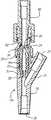
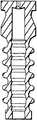
図面を参照すると、本発明の原理を実施する針なしバルブを組み込んだY字形コネクタが図1乃至3に例示されている。ここに、同じ番号は、複数の図の中の同じ又は対応する要素を示している特定のコネクタの形状は、例示の目的のみのために選択され、本発明の針なしバルブは、Jループ、T字形コネクタ、PRNアダプタ、ルアーロック、スリップルアー、管係合装置、アクセスピン等を含む種々のコネクタのどれでも実施することができるが、これらも限定的ではない。図1に示されるように、Y字形コネクタ12は、出口20で終わり、Y字形枝部口22を備えたY字形枝部21を有するハウジング14からなっている。また、この特定の実施形態では、ハウジングの一部を形成するルアーアダプタ16を備え、該アダプタは接続口18を有している。アダプタは、全てのANSI標準雄型ルアー取付部品、及び他のブラントカニューレ又は流体導管装置を受けるように形成されている。アクセス困難な状態又は閉じた位置では、ハウジングの内部に位置決めされたピストンヘッド24は、周囲の接続口18と同じ高さにあり、その中央にきつく閉じられたオリフィス26を有している。 Referring to the drawings, a Y-shaped connector incorporating a needleless valve embodying the principles of the present invention is illustrated in FIGS. Here, the same numbers indicate the specific connector shapes indicating the same or corresponding elements in the figures, for illustrative purposes only, and the needleless valve of the present invention comprises a J-loop, Any of a variety of connectors can be implemented including, but not limited to, a T-shaped connector, a PRN adapter, a luer lock, a ripple ripple, a tube engagement device, an access pin, and the like. As shown in FIG. 1, the Y-shaped connector 12 consists of a
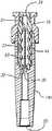
図2は、針なしバルブが閉じた位置にある図1のY字形コネクタの拡大断面を示している。Y字形枝部21はY字形枝部口22に通じ、ハウジング14の遠位部分19は、Y字形枝部口22と出口20との間に延びている。ハウジング14は円形断面の管状部分28、そのベース31に円形断面の出口オリフィス30、ベースから上方に延びる支持管29及び支持管を囲み、ベース内に形成された溝32を有している。管状部分28の外面は、その近位端の近くで、わずか内方に段状34になっていて、ルアーアダプタ16をその上に受け、超音波溶接用の外形を与える。あるいは、アダプタとハウジングは、スピン溶接、スナップ嵌め、接着又は他の手段によって結合されてもよい。
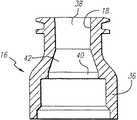
さらに図2は、ルアーアダプタ16とベース31との間に捕捉される管状部分28のボア33内の場所にあるピストン要素44を示している。ピストン要素44は全体で4つの蛇腹部分を含む。図4及び5に例示した別の実施形態は、支持管29がなくなり、ピストン要素44aがより浅い角度の全体で5つの蛇腹部分を有することを除いて、図2及び3に示した実施形態と同様である。図6に例示するように、ルアーアダプタ16の内部は、様々の直径の部分を有している。接続口18に直接隣接する部分は、ごくわずかに内方にテーパー状になっている標準ANSIルアーテーパー状部分38からなる。中央部分40は実質的により大きい直径を有し、テーパー状の傾斜/係止部分42によってテーパー状部分38から分けられる。さらに、中央部分40の内径は、以下の理由のために、本体14の管状部分28の内径よりわずかに大きい。最後に、ルアーアダプタ16は、超音波溶接用の外形を与えるために管状部分28の段状になった近位端34の上に嵌まるように寸法決めされたスカート36を含んでいる。アダプタ16は、暗くされた部屋の中でコネクタが見えるようにするために、蛍光色素を含有する材料で成形されるのがよい。FIG. 2 shows an enlarged cross section of the Y-shaped connector of FIG. 1 with the needleless valve in the closed position. The Y-shaped
Further, FIG. 2 shows the
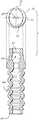
図2乃至5に一般的に示されるように、エラストマー変形するピストン要素44及び44aは、管状部分28のベース31とハウジング14のボア33内のルアーアダプタ16との間に捕捉される。その構造の詳細は、実施形態によりわずかに異なる一方、図7及び8に示す要素44aの図は多くの共通の特徴を提供する。この実施形態では、全部ゴムで成形されるピストン要素44aの構造は、一般的に、ピストン46及び圧縮性部分48を含んでいる。一方、ピストン46は、断面が楕円であるピストンヘッド24及び断面が円形である厚いテーパーロック部分50を含んでいる。水雷形ボア51がピストンヘッド24の長手方向軸線に沿って形成され、その近位端はオリフィス26で終わり、その遠位端はテーパー状リップシール59で終わっている。テーパー状リップシール59は、ボアの側の両側から延びる一対のリップ54を備えている。リップは、ためにボアの側から延びる円錐形部分を備え、シールとして機能する。テーパー部の角度は、ピストンが閉じた状態のときのバルブ内に存在する内圧がリップを互いの方に押すように選択され、それによりボアを閉じた状態に保持する。
図7と8を比較して明らかなように、水雷形ボア51は、その長軸53が楕円形のピストンヘッドの長軸55と垂直であるように向けられる。さらに、ピストンヘッド24とテーパー状係止部分54との間の移行部分57は、形状が楕円形及び円錐形であり、かかる楕円の長軸は、ピストンヘッドの長軸55と平行であり、ボア51の長軸53と垂直である。さらに、この形状は、水雷形ボアをその開放位置に付勢することを自然に補助する。この楕円形状は、楕円形ピストンヘッドの長軸に平行な外向きの力及び短軸に平行な内向きの力を作る。従って、雄型ルアーがピストンの頂部に力を加え、ピストンをアダプタ16の中央部分40に移動させるとき、内向きの力は、ピストンを長軸に垂直な方向に押す傾向があり、水雷型ボアを開くように引く傾向がある。As shown generally in FIGS. 2-5, elastomeric
As can be seen by comparing FIGS. 7 and 8, the torpedo shaped bore 51 is oriented so that its
ピストン要素44のテーパー状係止部分50は、圧縮されるのを防止するためにかなり厚い。このより厚い部分は、バルブ内のピストンをより高い内圧に保持するのを助け、下のバネ作用と上の水雷形ボアの開閉との間の仕切りとして作用する。ピストン要素44はハウジングのベース31にきつく着座するが、最大内圧が、ピストン44をハウジング14の外に押す実質的な力を与え、それによりその完全さを破壊する。ピストン要素のこの厚くされた部分50は、かかる内部の力で縮まず、ハウジングに適切にピストンを保持することをさらに保証している。
図9及び10は、管状部分28の内径が、その近位縁に形成された環状の溝35を設けるために、アダプタ16の中央部分40の内径に対して十分に小さくされた別の実施形態を例示するものである。円形の溝37の部分が、楕円形のピストンヘッド24の底部の長軸55の各端部に形成され、フック25を提供する。溝35が管状部分に係合するように形成される。雄型ルアー62がピストン24を、さらにアダプタ16内に押す込む結果、フックが溝に係合すると、フックはピストンの周囲のさらに移動するのに対抗し、図10に示すように、どんな雄型ルアーの力もボア51をより広く開かせることになる。The tapered
9 and 10 show another embodiment in which the inner diameter of the
図9は、一対の可撓性フラップ55がボア51のまわりから延び、ピストン24の内圧操作性を向上させた別の実施形態を示している。フラップの角度は、ピストンが閉じた状態のとき、バルブ内の内圧が互いの方にフラップを押し、それにより、ボア51を閉じた状態に保持するように選ばれる。別の実施形態では、フラップをより薄くより長く作ってもよい。ピストンが開いている状態のとき、それらをチェックバルブとして機能させてもよい。
図7及び8に戻ると、テーパー状係止部分50の中空内部及び圧縮性部分48の中空内部とともに、ボア51は、ピストン要素44全体を通る流体通路を形成している。圧縮性部分48は、図2乃至5、7、8及び9に示されるような蛇腹形状、あるいは、同じく、復原力を作るための長手方向軸線に沿った構造の制御されたつぶれを可能にする環状のリブ又はらせん状のリブのある構造でもよい。いくつかの実施形態を図12乃至15に例示し、様々なリブ又は蛇腹の数、寸法及び形状が可能であることを示す。ピストン要素の異なる形状は、流速、作動力、バネ戻り率、密封、ピストン保持力及びブラントカニューレの受け入れを向上させるのに使用されてもよい。また、ピストンの外形の変形は、内部環状溝及びピンチ点領域を取り除くことによって、容易に固まる流体に関するバルブの機能を向上させることができる。変更は、蛇腹の数、リブ、壁の厚さ、高さ、直径、デュロメータ、色及び外形を変えることを含む。ピンチ点領域は、ピストンの圧縮時に一緒になる蛇腹状のつぶれで形成され、一定の状態の下で、ピストンの縮みを妨害する固まった流体を捕らえることができる。FIG. 9 shows another embodiment in which a pair of
Returning to FIGS. 7 and 8, together with the hollow interior of the tapered locking
特に、図12は、図4、5、7、8及び9と同じく5つの蛇腹を有する圧縮性部分を示す。図13は、圧縮された形状がピンチ点を有さない外部にリブのある構造を有する圧縮性部分を示し、これらは必要とする作動力が小さい。図14は、作動力を増大させ、ピンチ点を減少させるために真っ直ぐな壁を有するピストン要素の圧縮性部分を示している。図15は、流速を増すために、圧縮時に平滑な内面を提供する圧縮性部分を示している。
図2、3、7及び8に再び戻ると、圧縮性部分48の遠位端45は、管状部分28のベース31の溝32に受けられ、支持管29及び出口オリフィス30のまわりにきつい密封を形成している。ピストン要素にFDA認定のシリコンオイルを潤滑剤として差し、コネクタ内のピストンの移動を容易にし、ピストンヘッド24を貫通するボア51が殺菌中に密封閉鎖されるのを防止する。
図16、17に例示する別の実施形態では、平らな柱の形状の支持構造が、ピストン46の圧縮性部分48内に突出するように管状部分28の内部に加えられている。柱は、ボア51の開放を補助するために、ピストン44の押し下げの時にピストン要素24のボア51内に延びる丸められた先端61を有している。柱の先端61と水雷形ボア51のとがった端部との間の隙間は流れを容易にし、一方、より薄い寸法の平らな柱63と圧縮性部分48の内面との間の隙間は、出口オリフィス30への流体の流れを可能にする。In particular, FIG. 12 shows a compressible portion having five bellows, similar to FIGS. 4, 5, 7, 8 and 9. FIG. 13 shows a compressible portion having a structure with ribs on the outside where the compressed shape does not have a pinch point, which require less actuation force. FIG. 14 shows the compressible portion of the piston element with straight walls to increase the actuation force and reduce the pinch point. FIG. 15 shows a compressible portion that provides a smooth inner surface during compression to increase the flow rate.
Returning again to FIGS. 2, 3, 7 and 8, the
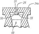
In another embodiment illustrated in FIGS. 16 and 17, a flat post-shaped support structure is added to the interior of the
図18及び19は、他の図面で示した圧縮バネの方法と異なり、ダイアフラム64の形状の伸張バネがピストンを閉じた位置に付勢するさらに別の実施形態を例示するものである。ダイアフラム64は、テーパー状係止部分50のベースから延び、その周囲のまわりに形成された環状のビード66を有している。かかるビードは、ルアーアダプタ16と管状部分28の近位縁との間に捕捉される。溝がこれらのそれぞれの要素に形成され、ビード要素66の確実なつかみを確保する。テーパー状係止部分50への取付け点に対するビード66の位置及びダイアフラム64の寸法は、ダイアフラムがピストン46のテーパー状肩部56を付勢し、アダプタ16のテーパー状係止部分42と接触するようにダイアフラムを予め装填することを確保する。
様々な図に示されたバルブの作動についてのより詳細な説明に移ると、楕円形のピストンヘッド24及び水雷形ボア51の寸法形状は、ヘッドがルアーアダプタ16のANSIテーパー状部分38の円形内部に圧迫されるとき、ボアがオリフィス26をきつく閉じるように完全につぶされ、テーパー状リップシール59の隣接するリップ54を互いに当接させるように、選択される。テーパー状係止部分50のテーパー状肩部56は、アダプタ16の傾斜/係止部分42に接触し、ピストンヘッド24の頂部が接続口18を越えて延びるのを防止する。ルアーアダプタ16の中央部分40の内径は、ピストンヘッド24がアダプタ16に位置決めされたとき、ピストンヘッド24が自由に楕円形状を呈することができるように、選択される。一方、これは、ボア51が再度元の水雷形状を呈することを可能にし、それにより、ピストン及びコネクタを通る流体通路を開く。18 and 19 illustrate yet another embodiment in which an extension spring in the form of a
Turning to a more detailed description of the operation of the valve shown in the various figures, the dimensions of the
図2乃至17を参照すると、針なしコネクタは、図2、4、16及び17に示すように、最初に、アクセスできない状態又は閉じた位置にある。圧縮性部分48は予め装填され、ピストンヘッド24をルアーアダプタ16のANSIルアーテーパー状部分38(図6)内に付勢する。テーパー状係止部分50の肩部56は、アダプタ16のテーパー状傾斜/係止部分42に接触し、ピストンヘッド24の頂部が接続オリフィス18を越えて延びるのを防止し、平滑で同じ高さの表面を形成する。ピストンヘッド24を貫通するボア51は、普通の楕円形状のピストンヘッドがANSIルアーテーパー状部分38の円形断面内に圧迫されることによってきつく圧迫されて閉じられる。水雷形ボアの鋭い尖った端部は、長軸に沿ったピストンヘッド24の圧縮によって、短軸に沿ったボアの圧縮時における、きついシールを容易にする。テーパー状リップシール59のテーパー状リップ54あるいは、図11に示す可撓性フラップ55は、さらに、ボア51が実質的な内圧を受けるときでさえも、密封されたままであることを確保する。図18及び19に示す別の実施形態に例示されたダイアフラム要素64は、同じく、ピストンヘッド24をアダプタ16のANSIルアーテーパー状部分内に付勢する。 Referring to FIGS. 2-17, the needleless connector is initially in an inaccessible or closed position, as shown in FIGS. The
コネクタに接続する直前に、ピストンヘッド24及び接続口18の縁は、例えば、平滑面上の殺菌スワイプを通すことによって清潔にされる。リッジ、溝、ギャップ又は突起物がないので、適切な清掃が可能となる。それから、コネクタ、ルアー係止部を有する又は有さない標準雄型ルアーによって接続することができるようになる。
雄型コネクタ60(図3、5、9、19)の雄型ルアーの先端62が、ゴムのピストンヘッド24の頂面と接触すると、それらの間の流体又は空気の通過を妨げるシールが形成される。十分な圧力を加えると、ピストン要素44の圧縮性部分48を圧縮し、あるいは、ダイアフラム64を伸ばす、そして、ピストンヘッド24をANSIルアーテーパー状部分38の外に移動させ、中央部分40(図6)内に移動させる。ピストンヘッドが、テーパー状傾斜/停止部分42を通過し、中央部分40に移動すると、そのより大きい内径により、ピストンヘッドは元の楕円形の開いた形状を呈する。一方、これは、ボア51を元の水雷形にし、それにより、ピストンヘッドを通る流体通路を開放する。雄型ルアーによる継続した圧力によって、ピストンヘッドは、主本体14の管状部分28内に進む。Immediately prior to connection to the connector, the edges of the
When the
図9及び10では、アダプタ16の中央部分40の直径と比較してわずかに小さい管状部分28の内径は、さらに、ゴム材料を雄型先端部60の外側のまわりに押し上げることによって、ボア51のオリフィス26をさらに拡大するのに役立つ。テーパー状係止部分50の底縁に形成されたフック25は、確実にボア51を引いて開くために、環状の溝35に係合する。ルアーアダプタ16の中央部分40は、短軸がピストンヘッド24のそれよりわずかに小さく寸法決めされた楕円形状を有するように形成されてもよい。これは、ピストンヘッドの短軸に沿ってピストンヘッドを圧縮し、ボアが完全に開いた形状を確保するのにさらに役立つ。図16及び17に示した別の実施形態では、柱63の丸められた先端部61のボアへのわずかな侵入によって、確実にボアを開ける。先端部が丸められ、比較的小さい直径を有しているという事実は、ピストンが損傷するのを防止する。示された柱63の実施形態は、ピストンが柱63と接触して移動するとき、ピストンを切らず、裂かず、又穴を開けない。
この位置では、コネクタは完全に接続し、短く、真っ直ぐで妨げられないコネクタを貫通する流体通路を提供する。流体の流れは、決してコネクタ内の通路でピストン要素の外側のまわりに流れない。“残りの”体積、即ち、雄型ルアーと出口オリフィスとの間の体積を0.04ml程度小さくすることができる。空気の漏れ、又は汚染物質の侵入、及び流体からの装置からの漏れは、常に防止される。In FIGS. 9 and 10, the inner diameter of the
In this position, the connector is fully connected and provides a fluid passage through the connector that is short, straight and unimpeded. The fluid flow never flows around the outside of the piston element in a passage in the connector. The “remaining” volume, ie the volume between the male luer and the exit orifice, can be reduced by as much as 0.04 ml. Air leaks or ingress of contaminants and leakage from the device from the fluid are always prevented.
図2及び3に示した実施形態と図16及び17に示した実施形態では、支持管29及び中央柱63は、それぞれ、圧縮性部分48がゆがみ、流体通路を閉じることを防止するのに役立つ。柱63の平らな断面は、いつでも流れるように、圧縮された蛇腹部分48に隣接した十分な隙間を確保する。図3に示した実施形態では、流体は支持管29の中央を通って向けられる。
雄型ルアーが引っ込められると、ピストン要素44の圧縮部分48又は図18及び19に示した別の実施形態の伸長可能なダイアフラム64によって作られた付勢力は、ピストンヘッド24と雄型ルアーの先端部62との間の接触を維持する。ルアーアダプタ16(図6)の中央部分40の直径は、管状部分28と比較してわずかに大きいので、ピストンのテーパー状係止部分50は、肩部56(図7)が傾斜/係止部分42(図6)に当接する位置まで自由に移動することができる。同時に、楕円形のピストンヘッド24は、テーパー状傾斜/係止部分42によって、ANSIルアーテーパー状部分38に案内され、そこで、ピストンヘッド24は、再度、ANSIルアーテーパー状部分の圧迫された円形形状に押し込まれ、ボア51を閉じ、確実なシールが再び確立される。同じ作用が、図18及び19に示した実施形態においても生ずる。In the embodiment shown in FIGS. 2 and 3 and the embodiment shown in FIGS. 16 and 17, the support tube 29 and the
When the male luer is retracted, the biasing force created by the
本発明の特定の形態を例示し、説明したが、当業者にとって、種々の変更が本発明の精神及び範囲から逸脱することなくなされることは明らかであろう。従って、本発明は限定的なものでなく、特許請求の範囲によってのみ限定される。 While particular forms of the invention have been illustrated and described, it would be obvious to those skilled in the art that various modifications can be made without departing from the spirit and scope of the invention. Accordingly, the invention is not limited but is only limited by the scope of the claims.
12 Y字形コネクタ
14 ハウジング
16 ルアーアダプタ
18 接続口
20 出口
22 Y字形枝部口
24 ピストンヘッド
26 オリフィス
28 管状部分
30 オリフィス
31 ベース
33 ボア
36 スカート
38 テーパー状部分
40 中央部分
42 テーパー状傾斜/係止部分
44 ピストン要素
46 ピストン
48 圧縮性部分
50 テーパー状係止部分
51 水雷形ボア
54 リップ
59 テーパー状リップシール
64 ダイアフラム12 Y-shaped
Claims (28)
Translated fromJapanese弾性変形可能なピストンヘッドであって、前記ピストンヘッドを貫通するボアを有し、前記第一部分と前記第二部分との間を移動できるように前記ハウジング内に受け入れられ、より小さい直径を有する前記第一部分の内部への前記ピストンヘッドの設置により、前記ボアを塞ぐように前記ビストンヘッドが変形され、その上より大きな直径を有する前記第二部分の内部への前記ピストンヘッドの設置により、前記ボアが塞がれずに、それにより前記接続口と前記出口オリフィスとの間の流路を提供する変形していない状態にすることできるピストンヘッド、および
流路を閉じるべく前記ピストンヘッドを第一部分内に付勢するよう構成された圧縮性部分を備え、前記ピストンヘッドおよび前記圧縮性部分が単一の非金属本体の部品であることからなる針なしコネクタバルブ。A hollow housing having a connection port and an exit orifice, disposed directly adjacent to the connection port, having a first portion having a first preselected cross-sectional shape and size, disposed adjacent to the first portion, and A hollow housing including a second portion having two preselected cross-sectional shapes and dimensions, the first portion and the second portion of the housing having a circular cross section, and the second portion having a diameter of the first portion A hollow housing consisting of larger than the diameter ,
An elastically deformable piston head having a bore extending through the piston head, received in the housing for movement between the first portion and the second portion, andhaving asmaller diameter The piston head is deformed so as to close the bore by installing the piston head inside the first portion, and the bore is formed by installing the piston head inside the second portionhaving a larger diameter thereon. A piston head that can be left undeformed, thereby providing a flow path between the connection port and the outlet orifice, and the piston head to close the flow path within the first portion. A compressible portion configured to bias, wherein the piston head and the compressible portion are part of a single non-metallic body; A needleless connector valve consisting of
楕円形断面の弾性変形可能なピストンヘッドであって、該ピストンヘッドを貫通して形成され、その長手方向軸線に沿って向けられたボアを有し、前記第一部分と前記第二部分との間を移動できるように前記ハウジング内に受け入れられ、前記第一部分に前記ピストンヘッドを設置することにより、前記ピストンヘッドが円形断面になるように変形され、それにより、前記ピストンヘッドを貫通して延びる前記ボアを塞ぎ、前記ビストンヘッドを前記第二部分に位置させることにより、前記ピストンヘッドを変形させていない楕円形状にし、前記ピストンヘッドを貫通して延びる前記ボアが塞がれず、それにより、前記接続口と前記出口オリフィスとの間の流路を提供するピストンヘッド、および
流路を閉じるべく、前記ピストンヘッドを第一部分内に付勢するよう構成された圧縮性部分であって、前記ピストンヘッドおよび前記圧縮性部分が単一の非金属本体の部品であることからなり、前記接続口へ流体導管装置の挿入が、前記ピストンヘッドを前記第二部分内に移動させて、前記流路を開くようにする前記ピストンヘッドを付勢し、流路を閉じる圧縮性部分、
を備えた針なしコネクタバルブ。A hollow housing having a connection port and an exit orifice, having a first portion with a circular cross section having a first diameter disposed directly adjacent to the connection port, and greater than a first diameter disposed adjacent to said first portion A hollow housing comprising a second portion having a circular cross section having a second diameter ,
An elastically deformable piston head of elliptical cross section, having a bore formed through the piston head and oriented along its longitudinal axis, between the first part and the second part The piston head is deformed to have a circular cross-section by being installed in the housing so that it can be moved, and extending in the piston head, thereby extending through the piston head. Closing the bore and positioning the Biston head in the second part makes the piston head an oval shape that is not deformed, and the bore extending through the piston head is not blocked, thereby allowing the connection A piston head providing a flow path between a mouth and the outlet orifice; and
A compressible portion configured to bias the piston head into the first portion to close the flow path, the piston head and the compressible portion being a single non-metallic body part; A compressible portion, wherein insertion of a fluid conduit device into the connection port urges the piston head to move the piston head into the second portion to open the flow path and closes the flow path;
Connector valve without needle with .
楕円形断面の弾性変形可能なピストンヘッドにして、該ピストンヘッドを通って延びるボアを有し、前記第一部分と前記第二部分との間を移動できるようにコネクタ装置内に配置され、前記ピストンヘッドをより小さい直径の前記第一部分に位置させることにより、前記ピストンヘッドが円形に変形され、前記ピストンへッドを貫通する前記ボアを塞ぎ、前記ピストンヘッドをより大きな直径の前記第二部分に位置させることにより、前記ピストンヘッドを変形していない楕円形状にし、前記ボアが塞がれず、前記接続口から前記出口オリフィスへの流路を提供することからなるピストンヘッド、および
流路を閉じるべくピストンヘッドを第一部分に付勢するよう構成された圧縮性部分であって、前記ピストンヘッドおよび前記圧縮性部分が単一の非金属本体の部品であり、流体管装置を接続口に挿入することにより、ピストンヘッドを第二部分に移動させ、流路を開くピストンヘッドを付勢し流路を閉じることからなる圧縮性部分、
を備えたバルブ機構。A valve mechanism incorporated in a connector device, wherein the connector device has a bore extending between a connection port and an outlet orifice, the bore having a small diameter first portion directly adjacent to the connection port; A valve mechanism having a large diameter second portion distally adjacent to the portion,
An elastically deformable piston head having an elliptical cross section, having a bore extending through the piston head, disposed in the connector device so as to be movable between the first part and the second part; By positioning the head in the first portion with the smaller diameter, the piston head is deformed into a circle, plugging the bore through the piston head and making the piston head into the second portion with the larger diameter. A piston head comprising: providing the flow path from the connection port to the outlet orifice, wherein the piston head is not deformed by being positioned, the bore is not blocked; and
A compressible portion configured to bias the piston head toward the first portion to close the flow path, the piston head and the compressible portion being a single non-metallic body part and connecting a fluid pipe device Compressible part consisting of moving the piston head to the second part by inserting it into the mouth, urging the piston head opening the flow path and closing the flow path,
Valve mechanism equipped with .
Applications Claiming Priority (1)
| Application Number | Priority Date | Filing Date | Title |
|---|---|---|---|
| US44202595A | 1995-05-16 | 1995-05-16 |
Related Parent Applications (1)
| Application Number | Title | Priority Date | Filing Date |
|---|---|---|---|
| JP8118653ADivisionJPH09108361A (en) | 1995-05-16 | 1996-05-14 | Needleless connector valve |
Publications (2)
| Publication Number | Publication Date |
|---|---|
| JP2006142053A JP2006142053A (en) | 2006-06-08 |
| JP4469802B2true JP4469802B2 (en) | 2010-06-02 |
Family
ID=23755223
Family Applications (2)
| Application Number | Title | Priority Date | Filing Date |
|---|---|---|---|
| JP8118653APendingJPH09108361A (en) | 1995-05-16 | 1996-05-14 | Needleless connector valve |
| JP2006045017AExpired - LifetimeJP4469802B2 (en) | 1995-05-16 | 2006-02-22 | Needleless connector valve |
Family Applications Before (1)
| Application Number | Title | Priority Date | Filing Date |
|---|---|---|---|
| JP8118653APendingJPH09108361A (en) | 1995-05-16 | 1996-05-14 | Needleless connector valve |
Country Status (14)
| Country | Link |
|---|---|
| US (1) | US5676346A (en) |
| EP (2) | EP0748635B1 (en) |
| JP (2) | JPH09108361A (en) |
| AT (2) | ATE228382T1 (en) |
| AU (1) | AU686942B2 (en) |
| CA (1) | CA2175021C (en) |
| DE (2) | DE69624982T2 (en) |
| DK (2) | DK1236482T3 (en) |
| ES (2) | ES2233742T3 (en) |
| HK (1) | HK1049453B (en) |
| NZ (1) | NZ286445A (en) |
| PL (1) | PL181486B1 (en) |
| PT (2) | PT1236482E (en) |
| SG (1) | SG64931A1 (en) |
Families Citing this family (279)
| Publication number | Priority date | Publication date | Assignee | Title |
|---|---|---|---|---|
| CA2124822C (en) | 1991-12-18 | 2007-07-03 | George A. Lopez | Medical valve |
| US6183448B1 (en)* | 1994-06-20 | 2001-02-06 | Bruno Franz P. Mayer | Needleless injection site |
| EP0728652B1 (en)* | 1995-02-27 | 2003-05-14 | Toyoda Gosei Co., Ltd. | Method of manufacturing a steering wheel and steering wheel manufactured according to this method |
| US5839715A (en)* | 1995-05-16 | 1998-11-24 | Alaris Medical Systems, Inc. | Medical adapter having needleless valve and sharpened cannula |
| US5738663A (en) | 1995-12-15 | 1998-04-14 | Icu Medical, Inc. | Medical valve with fluid escape space |
| US5776113A (en)* | 1996-03-29 | 1998-07-07 | Becton Dickinson And Company | Valved PRN adapter for medical access devices |
| US6079432A (en)* | 1996-07-02 | 2000-06-27 | Paradis; Joseph R. | Control of fluid flow by oval shaped valve member containing a cam interface |
| US7789864B2 (en) | 1996-11-18 | 2010-09-07 | Nypro Inc. | Luer-activated valve |
| PT952868E (en)* | 1996-11-18 | 2004-08-31 | Nypro Inc | VALVE CONICA-LUER LAVAVEL |
| US6883778B1 (en) | 1996-11-18 | 2005-04-26 | Nypro Inc. | Apparatus for reducing fluid drawback through a medical valve |
| US5807348A (en)* | 1996-11-27 | 1998-09-15 | Elcam Plastics | Needleless valve |
| US5814024A (en)* | 1996-11-27 | 1998-09-29 | Elcam Plastics | Needleless valve |
| US5938439A (en)* | 1996-12-13 | 1999-08-17 | Ivoclar A.G. | Syringe for dispensing viscous material and method |
| DE19651981C1 (en)* | 1996-12-13 | 1998-07-23 | Ivoclar Ag | Syringe for viscous masses and method for producing a syringe for viscous masses |
| WO1998026835A1 (en)* | 1996-12-16 | 1998-06-25 | Icu Medical, Inc. | Positive flow valve |
| AU774532B2 (en)* | 1996-12-16 | 2004-07-01 | Icu Medical, Inc. | Positive flow valve |
| US6245048B1 (en) | 1996-12-16 | 2001-06-12 | Icu Medical, Inc. | Medical valve with positive flow characteristics |
| US6102884A (en) | 1997-02-07 | 2000-08-15 | Squitieri; Rafael | Squitieri hemodialysis and vascular access systems |
| JPH10277161A (en)* | 1997-04-10 | 1998-10-20 | Hakko Denki Seisakusho:Kk | Injecting adapter for injection and withdrawal |
| DE29707410U1 (en)* | 1997-04-24 | 1997-10-16 | CareMed Vertriebsgesellschaft für Medical- und Laborprodukte mbH, 83052 Bruckmühl | Catheter valve |
| US6029946A (en)* | 1997-09-15 | 2000-02-29 | Tiva Medical Inc. | Needleless valve |
| US6221065B1 (en)* | 1998-04-03 | 2001-04-24 | Filtertek Inc. | Self-priming needle-free “Y”-adapter |
| US6117114A (en)* | 1998-05-07 | 2000-09-12 | Paradis; Joseph R. | Swabbable needleless valve adaptations |
| AU716965B2 (en) | 1998-05-12 | 2000-03-09 | Itw New Zealand Limited | Deformable valve head |
| US6491668B1 (en)* | 1998-12-03 | 2002-12-10 | Joseph R. Paradis | Needleless fluid transfer |
| JP3556116B2 (en)* | 1999-02-12 | 2004-08-18 | サーパス工業株式会社 | Socket for connector for transferring liquids etc. |
| JP4268289B2 (en)* | 1999-04-16 | 2009-05-27 | 良隆 安田 | Needleless mixed injection tube |
| US9814869B1 (en) | 1999-06-15 | 2017-11-14 | C.R. Bard, Inc. | Graft-catheter vascular access system |
| US6706022B1 (en) | 1999-07-27 | 2004-03-16 | Alaris Medical Systems, Inc. | Needleless medical connector with expandable valve mechanism |
| JP3935292B2 (en)* | 1999-09-16 | 2007-06-20 | テルモ株式会社 | connector |
| JP2001170187A (en) | 1999-12-17 | 2001-06-26 | Terumo Corp | Connector |
| US6695817B1 (en) | 2000-07-11 | 2004-02-24 | Icu Medical, Inc. | Medical valve with positive flow characteristics |
| JP2002035140A (en)* | 2000-07-21 | 2002-02-05 | Terumo Corp | Connector |
| US6755391B2 (en) | 2000-10-23 | 2004-06-29 | Nypro Inc. | Anti-drawback medical valve |
| JP4086458B2 (en)* | 2000-10-24 | 2008-05-14 | テルモ株式会社 | Disc |
| US6936031B2 (en)* | 2000-12-12 | 2005-08-30 | Gambro Dasco S.P.A. | Site for access to the inside of a channel, and corresponding cannula |
| US6745998B2 (en)* | 2001-08-10 | 2004-06-08 | Alaris Medical Systems, Inc. | Valved male luer |
| US6964406B2 (en)* | 2001-08-10 | 2005-11-15 | Alaris Medical Systems, Inc. | Valved male luer |
| US7044441B2 (en)* | 2001-08-10 | 2006-05-16 | Cardinal Health 303, Inc. | Valved male luer connector having sequential valve timing |
| WO2003018104A2 (en) | 2001-08-22 | 2003-03-06 | Nypro, Inc. | Medical valve with expandable seal member |
| US20070161970A1 (en) | 2004-04-16 | 2007-07-12 | Medrad, Inc. | Fluid Delivery System, Fluid Path Set, and Pressure Isolation Mechanism with Hemodynamic Pressure Dampening Correction |
| US7611503B2 (en)* | 2004-04-16 | 2009-11-03 | Medrad, Inc. | Fluid delivery system, fluid path set, sterile connector and improved drip chamber and pressure isolation mechanism |
| US8540698B2 (en)* | 2004-04-16 | 2013-09-24 | Medrad, Inc. | Fluid delivery system including a fluid path set and a check valve connector |
| US6869426B2 (en) | 2001-11-13 | 2005-03-22 | Nypro Inc. | Anti-drawback medical valve |
| US7753892B2 (en) | 2001-11-13 | 2010-07-13 | Nypro Inc. | Anti-drawback medical valve |
| US7837658B2 (en) | 2001-11-13 | 2010-11-23 | Nypro Inc. | Anti-drawback medical valve |
| JP4116785B2 (en)* | 2001-11-14 | 2008-07-09 | テルモ株式会社 | connector |
| US6802490B2 (en) | 2001-11-29 | 2004-10-12 | Alaris Medical Systems, Inc. | Needle free medical connector with expanded valve mechanism and method of fluid flow control |
| USD468016S1 (en) | 2001-11-30 | 2002-12-31 | Alaris Medical Systems, Inc. | Medical fluid connector |
| US6985870B2 (en) | 2002-01-11 | 2006-01-10 | Baxter International Inc. | Medication delivery system |
| CA2369640A1 (en)* | 2002-01-28 | 2003-07-28 | Christopher Green | Bi-directional tank valve |
| US6651956B2 (en)* | 2002-01-31 | 2003-11-25 | Halkey-Roberts Corporation | Slit-type swabable valve |
| US6875205B2 (en)* | 2002-02-08 | 2005-04-05 | Alaris Medical Systems, Inc. | Vial adapter having a needle-free valve for use with vial closures of different sizes |
| JP2003305129A (en)* | 2002-04-15 | 2003-10-28 | Koji Karasawa | Lateral injection pipe |
| ITMI20020819A1 (en) | 2002-04-18 | 2003-10-20 | Gambro Lundia Ab | CONNECTION ELEMENT AND CONNECTION DEVICE FOR MEDICAL USE PIPES |
| US7244249B2 (en)* | 2002-05-08 | 2007-07-17 | Cardinal Health 303, Inc. | Needle-free medical connector with expandable valve mechanism and method of fluid flow control |
| US7160272B1 (en)* | 2002-05-31 | 2007-01-09 | Elcam Plastic | Y-site medical valve |
| US7326188B1 (en) | 2002-08-02 | 2008-02-05 | Elcam Medical | Anesthesia manifold and induction valve |
| US7081109B2 (en)* | 2002-08-22 | 2006-07-25 | Baxa Corporation | Sterile docking apparatus and method |
| USD482447S1 (en) | 2002-09-17 | 2003-11-18 | Becton Dickinson And Company | Needleless luer access port |
| USD482121S1 (en) | 2002-09-17 | 2003-11-11 | Becton Dickinson And Company | Needleless luer access port |
| EP1566196A4 (en)* | 2002-10-03 | 2010-03-17 | Top Kk | Joining device |
| US7357792B2 (en) | 2002-10-29 | 2008-04-15 | Nypro Inc. | Positive push medical valve with internal seal |
| JP2004195016A (en)* | 2002-12-19 | 2004-07-15 | Top:Kk | Coupling device |
| US7125396B2 (en)* | 2002-12-30 | 2006-10-24 | Cardinal Health 303, Inc. | Safety catheter system and method |
| US20040181192A1 (en)* | 2003-03-11 | 2004-09-16 | Cuppy Michael John | Vascular access device and method of using same |
| US6871838B2 (en)* | 2003-04-03 | 2005-03-29 | B. Braun Medical Inc. | Injection port valve |
| EP1631496B1 (en)* | 2003-04-28 | 2014-02-26 | Medical Instill Technologies, Inc. | Container with valve assembly for filling and dispensing substances, and apparatus and method for filling |
| CN100420609C (en)* | 2003-04-28 | 2008-09-24 | 因斯蒂尔医学技术有限公司 | Container with valve assembly for filling and dispensing a substance and filling device and method |
| WO2004112866A2 (en)* | 2003-06-17 | 2004-12-29 | Filtertek Inc. | Fluid handling device and method of making same |
| JP4060247B2 (en)* | 2003-07-14 | 2008-03-12 | 株式会社大塚製薬工場 | Mouth member for drug container |
| US7914502B2 (en) | 2003-07-31 | 2011-03-29 | Nypro Inc. | Anti-drawback medical valve |
| US7762977B2 (en) | 2003-10-08 | 2010-07-27 | Hemosphere, Inc. | Device and method for vascular access |
| AU2004285367B2 (en)* | 2003-11-04 | 2009-12-24 | Terumo Kabushiki Kaisha | Connector |
| JP4728809B2 (en) | 2003-11-04 | 2011-07-20 | テルモ株式会社 | Connector |
| US8636721B2 (en) | 2003-11-20 | 2014-01-28 | Henry M. Jackson Foundation For The Advancement Of Military Medicine, Inc. | Portable hand pump for evacuation of fluids |
| US20050159724A1 (en)* | 2003-12-18 | 2005-07-21 | Enerson Jon R. | Needleless access vial |
| HK1077154A2 (en) | 2003-12-30 | 2006-02-03 | Icu Medical, Inc. | Valve assembly |
| JP4621029B2 (en)* | 2004-02-19 | 2011-01-26 | テルモ株式会社 | connector |
| US20050261637A1 (en)* | 2004-05-21 | 2005-11-24 | Halkey-Roberts Corporation | T-port with swabbable valve |
| WO2005120630A1 (en)* | 2004-06-07 | 2005-12-22 | Terumo Kabushiki Kaisha | Connector |
| US7520919B2 (en) | 2004-06-22 | 2009-04-21 | Gambro Lundia Ab | Transducer-protector device for medical apparatus |
| JP4739701B2 (en)* | 2004-07-02 | 2011-08-03 | フォルテ グロウ メディカル株式会社 | Side pipe |
| US10478607B2 (en) | 2004-08-09 | 2019-11-19 | Carefusion 303, Inc. | Connector for transferring fluid and method of use |
| US7600530B2 (en)* | 2004-08-09 | 2009-10-13 | Medegen, Inc. | Connector with check valve and method of use |
| US7306566B2 (en) | 2004-09-15 | 2007-12-11 | Cardinal Health 303, Inc. | Needle free blood collection device with male connector valve |
| US8337475B2 (en) | 2004-10-12 | 2012-12-25 | C. R. Bard, Inc. | Corporeal drainage system |
| US20060161115A1 (en) | 2004-11-05 | 2006-07-20 | Fangrow Thomas F | Soft-grip medical connector |
| US7651481B2 (en) | 2004-12-30 | 2010-01-26 | CareFusion 303 Inc. | Self-sealing male connector device with collapsible body |
| US7887519B2 (en) | 2005-01-14 | 2011-02-15 | Nypro Inc. | Valve with internal lifter |
| US7670322B2 (en) | 2005-02-01 | 2010-03-02 | Icu Medical, Inc. | Check valve for medical Y-site |
| US7510545B2 (en) | 2005-02-09 | 2009-03-31 | B. Braun Medical Inc. | Needleless access port valves |
| US7114701B2 (en) | 2005-03-02 | 2006-10-03 | B. Braun Medical, Inc. | Needleless access port valves |
| US7615035B2 (en) | 2005-03-24 | 2009-11-10 | B. Braun Medical Inc. | Needleless access port valves |
| US8100866B2 (en)* | 2005-03-24 | 2012-01-24 | B. Braun Medical Inc. | Needleless access port valves |
| US7314061B2 (en) | 2005-03-25 | 2008-01-01 | B. Braun Medical Inc. | Needleless access port valves |
| US7611505B2 (en)* | 2005-05-10 | 2009-11-03 | Baxa Corporation | Sterile docking apparatus and method |
| US7648491B2 (en)* | 2005-05-13 | 2010-01-19 | Bob Rogers | Medical substance transfer system |
| US7794422B2 (en)* | 2005-05-27 | 2010-09-14 | Medical Components, Inc. | Catheter port assembly for extracorporeal treatment |
| FR2886709B1 (en)* | 2005-06-06 | 2008-12-05 | Vygon Sa | CONNECTOR FOR LIQUID TRANSFER, IN PARTICULAR IN THE MEDICAL FIELD |
| US7998134B2 (en) | 2007-05-16 | 2011-08-16 | Icu Medical, Inc. | Medical connector |
| US20070088293A1 (en)* | 2005-07-06 | 2007-04-19 | Fangrow Thomas F Jr | Medical connector with closeable male luer |
| US8177772B2 (en) | 2005-09-26 | 2012-05-15 | C. R. Bard, Inc. | Catheter connection systems |
| US7695458B2 (en)* | 2005-10-11 | 2010-04-13 | Tyco Healthcare Group Lp | IV catheter with in-line valve and methods related thereto |
| US7691090B2 (en) | 2005-10-11 | 2010-04-06 | Tyco Healthcare Group Lp | IV catheter with in-line valve and methods related thereto |
| US8747387B2 (en)* | 2005-10-11 | 2014-06-10 | Covidien Lp | IV catheter with in-line valve and methods related thereto |
| CA2625824C (en)* | 2005-10-30 | 2013-12-17 | Medimop Medical Projects Ltd | Needleless additive control valve |
| US20070106228A1 (en)* | 2005-11-09 | 2007-05-10 | David Bell | Flexible valve for blood treatment set |
| US20070167901A1 (en)* | 2005-11-17 | 2007-07-19 | Herrig Judson A | Self-sealing residual compressive stress graft for dialysis |
| FR2894150B1 (en) | 2005-12-05 | 2008-01-04 | Ace Dev Solution Soc A Respons | CONNECTOR FOR MEDICAL USE |
| ITTO20060206A1 (en)* | 2006-03-17 | 2007-09-18 | Borla Ind | VALVE VALVE FOR MEDICAL LINES |
| FR2898812B1 (en)* | 2006-03-24 | 2008-06-13 | Technoflex Sa | LUER CONNECTOR, MEDICAL CONNECTOR AND TRANSFER SET COMPRISING SUCH A CONNECTOR |
| US7857284B2 (en) | 2006-04-11 | 2010-12-28 | Nypro Inc. | Medical valve with movable member |
| US7867204B2 (en) | 2006-05-04 | 2011-01-11 | B. Braun Medical Inc. | Needleless access port valves |
| USD571912S1 (en) | 2006-05-10 | 2008-06-24 | Baxa Corporation | Medical connector docking device |
| CA2660838A1 (en) | 2006-08-11 | 2008-02-21 | Nypro Inc. | Medical valve with expandable member |
| JP4847252B2 (en)* | 2006-08-11 | 2011-12-28 | 日本シャーウッド株式会社 | Luer connector connection structure and male connector used for it |
| EP2066369A4 (en)* | 2006-09-29 | 2013-04-03 | Covidien Lp | Surgical fluid transfer apparatus |
| US8167863B2 (en) | 2006-10-16 | 2012-05-01 | Carefusion 303, Inc. | Vented vial adapter with filter for aerosol retention |
| US8221363B2 (en) | 2006-10-18 | 2012-07-17 | Baxter Healthcare S.A. | Luer activated device with valve element under tension |
| US7981090B2 (en) | 2006-10-18 | 2011-07-19 | Baxter International Inc. | Luer activated device |
| US7753338B2 (en) | 2006-10-23 | 2010-07-13 | Baxter International Inc. | Luer activated device with minimal fluid displacement |
| BRPI0717401A2 (en) | 2006-10-25 | 2013-11-12 | Icu Medical Inc | CONNECTOR FOR MEDICAL USE |
| US20080132833A1 (en)* | 2006-11-06 | 2008-06-05 | Becton, Dickinson And Company | Vascular access devices including a tear-resistant septum |
| US20080128646A1 (en)* | 2006-12-05 | 2008-06-05 | Humitek, Inc. | Splines and caps for fluid ports |
| US20080128647A1 (en)* | 2006-12-05 | 2008-06-05 | Humitek, Inc. | Valves and valve assemblies for fluid ports |
| US20080171988A1 (en)* | 2007-01-17 | 2008-07-17 | Erblan Surgical, Inc. | Double-cone sphincter introducer assembly and integrated valve assembly |
| JP4526549B2 (en)* | 2007-04-16 | 2010-08-18 | インドゥストリー・ボルラ・ソシエタ・ペル・アチオニ | Medical line valve connector |
| US20090028750A1 (en)* | 2007-07-23 | 2009-01-29 | Ryan Dana Wm | Cleaning and Disinfection Swabbing Device for Needle-Free Intravenous (IV) Connectors |
| FR2920314B1 (en) | 2007-09-05 | 2010-07-30 | Gambro Lundia Ab | EXTRACORPOREAL BLOOD TREATMENT CIRCUIT AND LINE HAVING INFUSION SITE FOR THE OPTIMIZED MIXING OF FLUIDS |
| CA2644187A1 (en) | 2007-12-05 | 2009-06-05 | Tyco Healthcare Group Lp | Device for reducing microbial contamination |
| CA2646265A1 (en)* | 2007-12-20 | 2009-06-20 | Tyco Healthcare Group Lp | Cap assembly for use with a prefilled lock solution syringe |
| ITTO20080059A1 (en)* | 2008-01-29 | 2009-07-30 | Industrie Borla Spa | VALVE VALVE FOR MEDICAL LINES |
| US20110295181A1 (en) | 2008-03-05 | 2011-12-01 | Hemosphere, Inc. | Implantable and removable customizable body conduit |
| JP5492792B2 (en) | 2008-03-05 | 2014-05-14 | ヘモスフィア,インコーポレイテッド | Vascular access system |
| US20100030164A1 (en)* | 2008-08-04 | 2010-02-04 | Np Medical Inc. | Medical Valve with Raised Seal |
| US8480645B1 (en)* | 2008-08-22 | 2013-07-09 | Sambhu N. Choudhury | Multi-dose device for insertion into a vial and method of using the same |
| DE102008048988A1 (en)* | 2008-09-25 | 2010-04-08 | Fresenius Kabi Deutschland Gmbh | Device for connecting a syringe to a container or a hose line |
| US8145652B2 (en)* | 2008-10-09 | 2012-03-27 | International Business Machines Corporation | Automated propagation of non-conflicting queries in distributed databases |
| US9078992B2 (en) | 2008-10-27 | 2015-07-14 | Pursuit Vascular, Inc. | Medical device for applying antimicrobial to proximal end of catheter |
| US8679090B2 (en) | 2008-12-19 | 2014-03-25 | Icu Medical, Inc. | Medical connector with closeable luer connector |
| US9168366B2 (en) | 2008-12-19 | 2015-10-27 | Icu Medical, Inc. | Medical connector with closeable luer connector |
| US8864725B2 (en) | 2009-03-17 | 2014-10-21 | Baxter Corporation Englewood | Hazardous drug handling system, apparatus and method |
| WO2010109449A1 (en)* | 2009-03-22 | 2010-09-30 | Elcam Medical Agricultural Cooperative Association Ltd. | Closed male luer connector |
| US8454579B2 (en) | 2009-03-25 | 2013-06-04 | Icu Medical, Inc. | Medical connector with automatic valves and volume regulator |
| USD634007S1 (en) | 2009-03-31 | 2011-03-08 | Medimop Medical Projects Ltd. | Needleless additive control valve |
| US8057095B2 (en)* | 2009-04-23 | 2011-11-15 | Medtronic, Inc. | Multiple use temperature monitor adapter, system and method of using same |
| JP5836939B2 (en) | 2009-06-22 | 2015-12-24 | エヌピー メディカル インコーポレイテッド | Medical valve with improved back pressure seal |
| ES3004613T3 (en) | 2009-07-29 | 2025-03-12 | Icu Medical Inc | Fluid transfer devices |
| EP2480281B1 (en)* | 2009-09-04 | 2018-11-07 | B. Braun Melsungen AG | Selectively sealable male needleless connectors |
| TR200906911A1 (en) | 2009-09-08 | 2010-12-21 | Asset Medi̇kal Tasarim Sanayi̇ Ve Ti̇caret Anoni̇m Şi̇rketi̇ | Cleanable needle-free valve. |
| EP2305204A1 (en)* | 2009-09-30 | 2011-04-06 | Fresenius Medical Care Deutschland GmbH | Tubing set having an insert for the infusion of drugs |
| IL201323A0 (en) | 2009-10-01 | 2010-05-31 | Medimop Medical Projects Ltd | Fluid transfer device for assembling a vial with pre-attached female connector |
| US8764731B2 (en)* | 2009-10-02 | 2014-07-01 | Medline Industries, Inc. | Connector for fluid conduit with integrated luer access port |
| USD657056S1 (en) | 2009-10-02 | 2012-04-03 | Medline Industries, Inc. | Medical port |
| IL202069A0 (en) | 2009-11-12 | 2010-06-16 | Medimop Medical Projects Ltd | Fluid transfer device with sealing arrangement |
| IL202070A0 (en) | 2009-11-12 | 2010-06-16 | Medimop Medical Projects Ltd | Inline liquid drug medical device |
| US20110160696A1 (en) | 2009-12-31 | 2011-06-30 | Abbott Diabetes Care Inc. | Injection port device adapted for use with insulin pump |
| DK2512398T3 (en) | 2010-02-24 | 2014-10-13 | Medimop Medical Projects Ltd | Liquid drug transfer device with vented ampoule adapter |
| DK2512399T3 (en) | 2010-02-24 | 2015-06-22 | Medimop Medical Projects Ltd | Fluid transfer device with vent arrangement |
| USD644731S1 (en) | 2010-03-23 | 2011-09-06 | Icu Medical, Inc. | Medical connector |
| EP2550058B1 (en) | 2010-05-06 | 2014-03-26 | ICU Medical, Inc. | Medical connector with closeable luer connector |
| US8758306B2 (en) | 2010-05-17 | 2014-06-24 | Icu Medical, Inc. | Medical connectors and methods of use |
| US9138572B2 (en)* | 2010-06-24 | 2015-09-22 | Np Medical Inc. | Medical valve with fluid volume alteration |
| PL2627385T3 (en)* | 2010-10-12 | 2016-09-30 | Medical valve assembly | |
| IL209290A0 (en) | 2010-11-14 | 2011-01-31 | Medimop Medical Projects Ltd | Inline liquid drug medical device having rotary flow control member |
| CN102553027B (en)* | 2010-12-22 | 2015-06-03 | 潘秀凤 | No positive and negative pressure needle-free injection connector |
| JP5630288B2 (en)* | 2011-01-24 | 2014-11-26 | 株式会社ジェイ・エム・エス | Male member cover and male member with cover |
| US9919099B2 (en)* | 2011-03-14 | 2018-03-20 | Minipumps, Llc | Implantable drug pumps and refill devices therefor |
| IL212420A0 (en) | 2011-04-17 | 2011-06-30 | Medimop Medical Projects Ltd | Liquid drug transfer assembly |
| JP2012223278A (en)* | 2011-04-18 | 2012-11-15 | Paru Medical:Kk | Medical connector |
| WO2012162259A2 (en) | 2011-05-20 | 2012-11-29 | Excelsior Medical Corporation | Caps for cannula access devices |
| WO2013009998A2 (en) | 2011-07-12 | 2013-01-17 | Pursuit Vascular, Inc. | Device for delivery of antimicrobial agent into trans-dermal catheter |
| JP6199866B2 (en) | 2011-09-06 | 2017-09-20 | メリット・メディカル・システムズ・インコーポレイテッドMerit Medical Systems,Inc. | Vascular access system having a connecting portion |
| ES2664517T3 (en) | 2011-09-09 | 2018-04-19 | Icu Medical, Inc. | Medical connectors with fluid resistant coupling interfaces |
| US9155864B2 (en)* | 2011-10-06 | 2015-10-13 | Becton, Dickinson And Company | Multiple use blood control valve with center and circumferential slits |
| IL215699A0 (en) | 2011-10-11 | 2011-12-29 | Medimop Medical Projects Ltd | Liquid drug reconstitution assemblage for use with iv bag and drug vial |
| KR102145639B1 (en) | 2011-12-22 | 2020-08-19 | 아이씨유 메디칼 인코퍼레이티드 | Fluid transfer devices and methods of use |
| WO2013109794A1 (en) | 2012-01-17 | 2013-07-25 | Py Daniel C | Multiple dose vial and method |
| US8801678B2 (en) | 2012-01-20 | 2014-08-12 | Carefusion 303, Inc. | Piston for a needleless valve system |
| USD720451S1 (en) | 2012-02-13 | 2014-12-30 | Medimop Medical Projects Ltd. | Liquid drug transfer assembly |
| USD737436S1 (en) | 2012-02-13 | 2015-08-25 | Medimop Medical Projects Ltd. | Liquid drug reconstitution assembly |
| US9737686B2 (en)* | 2012-03-12 | 2017-08-22 | Becton, Dickinson And Company | Catheter adapter port valve |
| IL219065A0 (en) | 2012-04-05 | 2012-07-31 | Medimop Medical Projects Ltd | Fluid transfer device with manual operated cartridge release arrangement |
| IL221635A0 (en) | 2012-08-26 | 2012-12-31 | Medimop Medical Projects Ltd | Drug vial mixing and transfer device for use with iv bag and drug vial |
| IL221634A0 (en) | 2012-08-26 | 2012-12-31 | Medimop Medical Projects Ltd | Universal drug vial adapter |
| DK2872100T3 (en) | 2012-09-13 | 2017-07-10 | Medimop Medical Projects Ltd | Telescopic female adapter for drug ampoule |
| JP6311934B2 (en)* | 2012-09-26 | 2018-04-18 | ニプロ株式会社 | Needleless connector |
| USD734868S1 (en) | 2012-11-27 | 2015-07-21 | Medimop Medical Projects Ltd. | Drug vial adapter with downwardly depending stopper |
| US9144672B2 (en)* | 2013-03-13 | 2015-09-29 | Carefusion 303, Inc. | Needleless connector with compressible valve |
| US9433737B2 (en)* | 2013-03-15 | 2016-09-06 | Covidien Lp | Cuff pressure measurement device for a tracheal tube |
| JP6370364B2 (en) | 2013-03-15 | 2018-08-08 | アイシーユー・メディカル・インコーポレーテッド | Medical connector |
| IL225734A0 (en) | 2013-04-14 | 2013-09-30 | Medimop Medical Projects Ltd | Ready-to-use drug vial assemblages including drug vial and drug vial closure having fluid transfer member, and drug vial closure therefor |
| CN105228676B (en) | 2013-05-10 | 2018-01-05 | 麦迪麦珀医疗工程有限公司 | Include the medical treatment device of the vial adapter with inline dry kit |
| US9861763B2 (en) | 2013-07-01 | 2018-01-09 | Credence Medsystems, Inc. | Safety syringe |
| USD765837S1 (en) | 2013-08-07 | 2016-09-06 | Medimop Medical Projects Ltd. | Liquid transfer device with integral vial adapter |
| DE212014000169U1 (en) | 2013-08-07 | 2016-03-14 | Medimop Medical Projects Ltd. | Fluid transfer devices for use with infusion fluid containers |
| USD767124S1 (en) | 2013-08-07 | 2016-09-20 | Medimop Medical Projects Ltd. | Liquid transfer device with integral vial adapter |
| ITMO20130264A1 (en)* | 2013-09-25 | 2015-03-26 | Giuseppe Maffei | CONNECTOR WITHOUT NEEDLE |
| ITMO20130263A1 (en)* | 2013-09-25 | 2015-03-26 | Giuseppe Maffei | CONNECTOR WITHOUT NEEDLE |
| US10300217B2 (en) | 2013-11-15 | 2019-05-28 | Credence Medsystems, Inc. | System and method for drug delivery with a safety syringe |
| ES2805051T3 (en) | 2013-11-25 | 2021-02-10 | Icu Medical Inc | Procedures and system for filling I.V. bags with therapeutic liquid |
| AU2014364218B2 (en) | 2013-12-11 | 2019-06-06 | Icu Medical, Inc. | Check valve |
| US10682453B2 (en) | 2013-12-20 | 2020-06-16 | Merit Medical Systems, Inc. | Vascular access system with reinforcement member |
| USD734456S1 (en)* | 2014-02-03 | 2015-07-14 | Nordson Corporation | Hub for a medical applicator |
| PL3134152T3 (en) | 2014-04-24 | 2021-12-20 | Credence Medsystems Inc. | System for safety syringe |
| EP3137122B1 (en) | 2014-05-02 | 2019-09-04 | Excelsior Medical Corporation | Strip package for antiseptic cap |
| US10350396B2 (en)* | 2014-06-27 | 2019-07-16 | Acclarent, Inc. | Vent cap for a Eustachian tube dilation system |
| USD757933S1 (en) | 2014-09-11 | 2016-05-31 | Medimop Medical Projects Ltd. | Dual vial adapter assemblage |
| USD786427S1 (en) | 2014-12-03 | 2017-05-09 | Icu Medical, Inc. | Fluid manifold |
| USD793551S1 (en) | 2014-12-03 | 2017-08-01 | Icu Medical, Inc. | Fluid manifold |
| JP6358724B2 (en) | 2015-01-05 | 2018-07-18 | ウエスト・ファーマ.サービシーズ・イスラエル,リミテッド | Dual vial adapter assembly with easy removable pill adapter to ensure accurate use |
| US9682189B2 (en) | 2015-02-27 | 2017-06-20 | Carefusion 2200, Inc. | Smart check valve |
| WO2016157886A1 (en)* | 2015-03-30 | 2016-10-06 | テルモ株式会社 | Medical connector |
| DK3294404T3 (en) | 2015-05-08 | 2025-09-08 | Icu Medical Inc | MEDICAL CONNECTORS CONFIGURED TO RECEIVE EMISSIONS OF THERAPEUTIC AGENTS |
| WO2017009822A1 (en) | 2015-07-16 | 2017-01-19 | Medimop Medical Projects Ltd | Liquid drug transfer devices for secure telescopic snap fit on injection vials |
| JP1557742S (en)* | 2015-08-05 | 2016-09-05 | ||
| CA2998359C (en)* | 2015-09-18 | 2024-02-06 | Becton, Dickinson And Company | Safety iv catheter with molded-open blood control valve |
| US10195415B2 (en) | 2015-09-21 | 2019-02-05 | Carefusion 303, Inc. | Priming device |
| US10758720B2 (en) | 2015-10-28 | 2020-09-01 | Carefusion 303, Inc. | Closed IV access device with y-port needle-free connector |
| USD801522S1 (en) | 2015-11-09 | 2017-10-31 | Medimop Medical Projects Ltd. | Fluid transfer assembly |
| CN115721558A (en) | 2015-11-25 | 2023-03-03 | 西部制药服务以色列有限公司 | Dual vial adapter assembly comprising a drug vial adapter having a self-sealing inlet valve |
| EP4534065A3 (en) | 2015-12-04 | 2025-06-04 | ICU Medical, Inc. | Systems methods and components for transferring medical fluids |
| EP4309725A3 (en) | 2016-02-18 | 2024-04-17 | Smiths Medical ASD, Inc. | Closed system catheter |
| DE102016203518A1 (en) | 2016-03-03 | 2017-09-07 | B. Braun Melsungen Ag | Connecting device of a medical infusion system |
| IL245803A0 (en) | 2016-05-24 | 2016-08-31 | West Pharma Services Il Ltd | Dual vial adapter assemblages including vented drug vial adapter and vented liquid vial adapter |
| IL245800A0 (en) | 2016-05-24 | 2016-08-31 | West Pharma Services Il Ltd | Dual vial adapter assemblages including identical twin vial adapters |
| IL246073A0 (en) | 2016-06-06 | 2016-08-31 | West Pharma Services Il Ltd | Fluid transfer devices for use with drug pump cartridge having slidable driving plunger |
| CN105963824A (en)* | 2016-06-28 | 2016-09-28 | 李卫林 | Rotary type needle-free connector keeping positive pressure constantly |
| WO2018017365A1 (en) | 2016-07-18 | 2018-01-25 | Merit Medical Systems, Inc. | Inflatable radial artery compression device |
| USD851745S1 (en) | 2016-07-19 | 2019-06-18 | Icu Medical, Inc. | Medical fluid transfer system |
| EP3487468B1 (en) | 2016-07-25 | 2025-10-01 | ICU Medical, Inc. | Systems and components for trapping air bubbles in medical fluid transfer modules and systems |
| IL247376A0 (en) | 2016-08-21 | 2016-12-29 | Medimop Medical Projects Ltd | Syringe assembly |
| PT3525865T (en) | 2016-10-14 | 2022-11-17 | Icu Medical Inc | Sanitizing caps for medical connectors |
| USD808013S1 (en) | 2016-10-27 | 2018-01-16 | Smiths Medical Asd, Inc. | Catheter |
| WO2018089625A2 (en) | 2016-11-10 | 2018-05-17 | Merit Medical Systems, Inc. | Anchor device for vascular anastomosis |
| USD832430S1 (en) | 2016-11-15 | 2018-10-30 | West Pharma. Services IL, Ltd. | Dual vial adapter assemblage |
| IL249408A0 (en) | 2016-12-06 | 2017-03-30 | Medimop Medical Projects Ltd | Liquid transfer device for use with infusion liquid container and pincers-like hand tool for use therewith for releasing intact drug vial therefrom |
| JP6286522B1 (en)* | 2016-12-21 | 2018-02-28 | アトムメディカル株式会社 | Connector for liquid injection |
| US11383072B2 (en) | 2017-01-12 | 2022-07-12 | Merit Medical Systems, Inc. | Methods and systems for selection and use of connectors between conduits |
| EP4461262A3 (en) | 2017-01-25 | 2025-02-26 | Merit Medical Systems, Inc. | Systems for facilitating laminar flow between conduits |
| US11026704B2 (en) | 2017-03-06 | 2021-06-08 | Merit Medical Systems, Inc. | Vascular access assembly declotting systems and methods |
| JP1592653S (en)* | 2017-03-22 | 2017-12-11 | ||
| US10925710B2 (en) | 2017-03-24 | 2021-02-23 | Merit Medical Systems, Inc. | Subcutaneous vascular assemblies for improving blood flow and related devices and methods |
| IL251458A0 (en) | 2017-03-29 | 2017-06-29 | Medimop Medical Projects Ltd | User actuated liquid drug transfer devices for use in ready-to-use (rtu) liquid drug transfer assemblages |
| WO2018204206A2 (en) | 2017-05-01 | 2018-11-08 | Icu Medical, Inc. | Medical fluid connectors and methods for providing additives in medical fluid lines |
| WO2019014444A2 (en) | 2017-07-14 | 2019-01-17 | Merit Medical Systems, Inc. | Releasable conduit connectors |
| US11911585B2 (en) | 2017-07-20 | 2024-02-27 | Merit Medical Systems, Inc. | Methods and systems for coupling conduits |
| HUE069141T2 (en) | 2017-08-22 | 2025-02-28 | Hoffmann La Roche | Self-sealing septum |
| IL254802A0 (en) | 2017-09-29 | 2017-12-31 | Medimop Medical Projects Ltd | Dual vial adapter assemblages with twin vented female vial adapters |
| US11331458B2 (en) | 2017-10-31 | 2022-05-17 | Merit Medical Systems, Inc. | Subcutaneous vascular assemblies for improving blood flow and related devices and methods |
| EP3988074A1 (en) | 2017-12-03 | 2022-04-27 | West Pharma. Services IL, Ltd | Liquid transfer device with telescopic vial adapter for use with infusion liquid container and discrete injection vial |
| EP3569282B1 (en)* | 2018-05-16 | 2024-04-17 | CODAN Medizinische Geräte GmbH | Valve with prefabricated compressed dilatable opening |
| US11857320B2 (en) | 2018-06-08 | 2024-01-02 | Smiths Medical Asd, Inc. | Blood sequestration device and method |
| USD903864S1 (en) | 2018-06-20 | 2020-12-01 | West Pharma. Services IL, Ltd. | Medication mixing apparatus |
| JP1630477S (en) | 2018-07-06 | 2019-05-07 | ||
| US11534595B2 (en) | 2018-11-07 | 2022-12-27 | Icu Medical, Inc. | Device for delivering an antimicrobial composition into an infusion device |
| US11541220B2 (en) | 2018-11-07 | 2023-01-03 | Icu Medical, Inc. | Needleless connector with antimicrobial properties |
| US11517732B2 (en) | 2018-11-07 | 2022-12-06 | Icu Medical, Inc. | Syringe with antimicrobial properties |
| US11400195B2 (en) | 2018-11-07 | 2022-08-02 | Icu Medical, Inc. | Peritoneal dialysis transfer set with antimicrobial properties |
| US11541221B2 (en) | 2018-11-07 | 2023-01-03 | Icu Medical, Inc. | Tubing set with antimicrobial properties |
| EP3883638A1 (en) | 2018-11-21 | 2021-09-29 | ICU Medical, Inc. | Antimicrobial device comprising a cap with ring and insert |
| US12246157B2 (en) | 2019-01-14 | 2025-03-11 | Becton, Dickinson And Company | Needleless access connector facilitating instrument delivery to a catheter assembly |
| USD923812S1 (en) | 2019-01-16 | 2021-06-29 | West Pharma. Services IL, Ltd. | Medication mixing apparatus |
| JP1648075S (en) | 2019-01-17 | 2019-12-16 | ||
| JP7209849B2 (en) | 2019-01-18 | 2023-01-20 | ウェスト・ファーマ・サービシーズ・アイエル・リミテッド | Liquid transfer device for use with IV bottles |
| US11918542B2 (en) | 2019-01-31 | 2024-03-05 | West Pharma. Services IL, Ltd. | Liquid transfer device |
| JP7284289B2 (en) | 2019-04-09 | 2023-05-30 | ウェスト ファーマ サービシーズ イスラエル リミテッド | Infusion device with integrated syringe |
| KR20240122586A (en) | 2019-04-30 | 2024-08-12 | 웨스트 파마. 서비시즈 일, 리미티드 | Liquid transfer device with dual lumen iv spike |
| US11590057B2 (en) | 2020-04-03 | 2023-02-28 | Icu Medical, Inc. | Systems, methods, and components for transferring medical fluids |
| USD956958S1 (en) | 2020-07-13 | 2022-07-05 | West Pharma. Services IL, Ltd. | Liquid transfer device |
| US20220016336A1 (en) | 2020-07-14 | 2022-01-20 | Cameron Edds | Fastener for medical tubing |
| WO2022102301A1 (en)* | 2020-11-12 | 2022-05-19 | テルモ株式会社 | Medical connector |
| JPWO2022102300A1 (en)* | 2020-11-12 | 2022-05-19 | ||
| CA3204371A1 (en) | 2020-12-07 | 2022-06-16 | Icu Medical, Inc. | Peritoneal dialysis caps, systems and methods |
| US12426864B2 (en) | 2021-06-18 | 2025-09-30 | Merit Medical Systems, Inc. | Hemostasis devices and methods of use |
| US20240151339A1 (en)* | 2022-11-08 | 2024-05-09 | Carefusion 303, Inc. | Fluid connector assembly with neutral fluid displacement that limits connector damage |
| US12151078B2 (en)* | 2022-11-14 | 2024-11-26 | Becton, Dickinson And Company | Force-controlled release connector with integrated safety features |
| KR102623165B1 (en)* | 2022-11-25 | 2024-01-11 | 윤성호 | Medical needleless connectors |
Family Cites Families (62)
| Publication number | Priority date | Publication date | Assignee | Title |
|---|---|---|---|---|
| US558848A (en)* | 1896-04-21 | Julius schafer | ||
| US584091A (en)* | 1897-06-08 | Automatic valve for beer-taps | ||
| US41392A (en)* | 1864-01-26 | Samuel j | ||
| US515626A (en)* | 1894-02-27 | Albert sttjtzer and julius schafer | ||
| US2212733A (en)* | 1937-12-09 | 1940-08-27 | Gail G Grigsby | Valve |
| US2342192A (en)* | 1941-03-28 | 1944-02-22 | Gail G Grigsby | Flexible pipe coupling |
| US2371434A (en)* | 1943-05-03 | 1945-03-13 | Arthur H Eppler | Sandblast mixer valve |
| US2585527A (en)* | 1948-06-24 | 1952-02-12 | John M Adams | Slitted resilient closure for containers |
| DE884441C (en)* | 1951-10-04 | 1953-07-27 | Eitel Moehring | Passage barrier |
| US3002660A (en)* | 1959-06-10 | 1961-10-03 | Clarence R Taylor | Dispensing device |
| US3349972A (en)* | 1966-10-24 | 1967-10-31 | Carlton L Whiteford | Dispenser closure |
| US3490732A (en)* | 1967-02-24 | 1970-01-20 | Union Carbide Corp | Pressure programmed check valve |
| US3624800A (en)* | 1969-09-29 | 1971-11-30 | Illinois Tool Works | Fluid flow control means |
| US3823840A (en)* | 1972-08-04 | 1974-07-16 | Silver J | Prepunctured closure |
| US3837381A (en)* | 1972-12-26 | 1974-09-24 | Prod Adex Sa | Shuttoff valve device |
| US3853127A (en)* | 1973-04-03 | 1974-12-10 | R Spademan | Elastic sealing member |
| GB1490349A (en)* | 1974-03-18 | 1977-11-02 | Gooch & Co Ltd J | Pinch valves |
| US3977400A (en)* | 1974-11-29 | 1976-08-31 | Deseret Pharmaceutical Co., Inc. | Catheter placement unit with resilient sleeve and manual sleeve closure |
| US4334551A (en)* | 1979-04-30 | 1982-06-15 | Becton Dickinson & Company | Connector |
| US4244478A (en)* | 1979-06-27 | 1981-01-13 | Mpl, Inc. | Closure assembly for unit dose vial |
| US4475548A (en)* | 1982-06-01 | 1984-10-09 | Rudolph Muto | Fitting for endotracheal tube apparatus and method of making the fitting |
| US4655752A (en)* | 1983-10-24 | 1987-04-07 | Acufex Microsurgical, Inc. | Surgical cannula |
| US4809679A (en)* | 1986-11-19 | 1989-03-07 | Olympus Optical Co., Ltd. | Forceps plug for endoscopes |
| US4752287A (en)* | 1986-12-30 | 1988-06-21 | Bioresearch, Inc. | Syringe check valve |
| US5295658A (en)* | 1987-04-27 | 1994-03-22 | Vernay Laboratories, Inc. | Medical coupling site including slit reinforcing members |
| US5251873B1 (en)* | 1992-06-04 | 1995-05-02 | Vernay Laboratories | Medical coupling site. |
| US5100394A (en)* | 1988-01-25 | 1992-03-31 | Baxter International Inc. | Pre-slit injection site |
| US5135489A (en)* | 1988-01-25 | 1992-08-04 | Baxter International Inc. | Pre-slit injection site and tapered cannula |
| CA1335167C (en)* | 1988-01-25 | 1995-04-11 | Steven C. Jepson | Pre-slit injection site and associated cannula |
| US5211638A (en)* | 1988-01-25 | 1993-05-18 | Baxter International Inc. | Pre-slit injection site |
| DE3809127C1 (en)* | 1988-03-18 | 1989-04-13 | B. Braun Melsungen Ag, 3508 Melsungen, De | |
| US4874377A (en)* | 1988-05-26 | 1989-10-17 | Davis Newgard Revocable Family Living Trust | Self-occluding intravascular cannula assembly |
| US5064416A (en)* | 1988-05-26 | 1991-11-12 | Newgard Kent W | Self-occluding intravascular cannula assembly |
| US4867198A (en)* | 1988-10-11 | 1989-09-19 | Faust Bobby G | Adjustable flow regulating valve |
| JPH02162229A (en)* | 1988-12-16 | 1990-06-21 | Terumo Corp | liquid collection tube |
| US5080654A (en)* | 1989-09-18 | 1992-01-14 | Applied Medical Technology, Inc. | Fluid injection device for intravenous delivery system |
| DE4000764A1 (en)* | 1990-01-12 | 1991-07-18 | Braun Melsungen Ag | APPROACH |
| US5053013A (en)* | 1990-03-01 | 1991-10-01 | The Regents Of The University Of Michigan | Implantable infusion device |
| US5203775A (en)* | 1990-09-18 | 1993-04-20 | Medex, Inc. | Needleless connector sample site |
| US5201717A (en)* | 1990-12-05 | 1993-04-13 | Philip Wyatt | Safety enclosure |
| US5122123A (en)* | 1991-01-30 | 1992-06-16 | Vaillancourt Vincent L | Closed system connector assembly |
| US5071017A (en)* | 1991-02-15 | 1991-12-10 | Stuli Iene | Closure cap construction with slitted flexible diaphragm |
| DE9105229U1 (en)* | 1991-04-27 | 1991-06-13 | B. Braun Melsungen Ag, 3508 Melsungen | Valve device for a catheter |
| US5199948A (en)* | 1991-05-02 | 1993-04-06 | Mcgaw, Inc. | Needleless valve |
| US5125903A (en)* | 1991-08-01 | 1992-06-30 | Medtronic, Inc. | Hemostasis valve |
| US5242432A (en)* | 1991-09-26 | 1993-09-07 | Ivac | Needleless adapter |
| US5201725A (en)* | 1991-09-26 | 1993-04-13 | Ivac | Needle free i.v. adapter |
| FR2684007B1 (en)* | 1991-11-25 | 1997-04-18 | Vygon | MONOBLOCK CONNECTOR WITH INTERNAL INJECTION NEEDLE FOR CONNECTING A LIQUID CIRCUIT, ESPECIALLY FOR MEDICAL APPLICATIONS. |
| US5360413A (en)* | 1991-12-06 | 1994-11-01 | Filtertek, Inc. | Needleless access device |
| CA2124822C (en)* | 1991-12-18 | 2007-07-03 | George A. Lopez | Medical valve |
| US5215538A (en)* | 1992-02-05 | 1993-06-01 | Abbott Laboratories | Connector-activated in-line valve |
| US5501426A (en)* | 1992-06-04 | 1996-03-26 | Vernay Laboratories, Inc. | Medical coupling site valve body |
| US5242393A (en)* | 1992-06-18 | 1993-09-07 | Becton, Dickinson And Company | Valved blunt cannula injection site |
| US5300034A (en)* | 1992-07-29 | 1994-04-05 | Minnesota Mining And Manufacturing Company | Iv injection site for the reception of a blunt cannula |
| US5269771A (en)* | 1993-02-24 | 1993-12-14 | Thomas Medical Products, Inc. | Needleless introducer with hemostatic valve |
| US5354275A (en)* | 1993-09-13 | 1994-10-11 | Minnesota Mining And Manufacturing Company | Injection or sampling site |
| US5529278A (en)* | 1993-11-19 | 1996-06-25 | Novoste Corporation | Fluid access and flow control valve |
| US5487728A (en)* | 1994-05-19 | 1996-01-30 | Vaillancourt; Vincent L. | Connector assembly |
| US5470319A (en)* | 1994-06-20 | 1995-11-28 | Critical Device Corporation | Needleless injection site |
| US5514116A (en)* | 1994-10-24 | 1996-05-07 | Vlv Associates | Connector |
| US5509912A (en)* | 1994-10-24 | 1996-04-23 | Vlv Associates | Connector |
| US5501676A (en)* | 1995-01-13 | 1996-03-26 | Sanofi Winthrop, Inc. | Coupling system for safety cannula |
- 1996
- 1996-04-24NZNZ286445Apatent/NZ286445A/ennot_activeIP Right Cessation
- 1996-04-25CACA002175021Apatent/CA2175021C/ennot_activeExpired - Lifetime
- 1996-04-29ATAT96106740Tpatent/ATE228382T1/enactive
- 1996-04-29DKDK02011774Tpatent/DK1236482T3/enactive
- 1996-04-29PTPT02011774Tpatent/PT1236482E/enunknown
- 1996-04-29EPEP96106740Apatent/EP0748635B1/ennot_activeExpired - Lifetime
- 1996-04-29ATAT02011774Tpatent/ATE281869T1/enactive
- 1996-04-29PTPT96106740Tpatent/PT748635E/enunknown
- 1996-04-29DKDK96106740Tpatent/DK0748635T3/enactive
- 1996-04-29ESES02011774Tpatent/ES2233742T3/ennot_activeExpired - Lifetime
- 1996-04-29ESES96106740Tpatent/ES2188688T3/ennot_activeExpired - Lifetime
- 1996-04-29DEDE69624982Tpatent/DE69624982T2/ennot_activeExpired - Lifetime
- 1996-04-29DEDE69633839Tpatent/DE69633839T2/ennot_activeExpired - Lifetime
- 1996-04-29EPEP02011774Apatent/EP1236482B1/ennot_activeExpired - Lifetime
- 1996-05-02AUAU52038/96Apatent/AU686942B2/ennot_activeExpired
- 1996-05-14JPJP8118653Apatent/JPH09108361A/enactivePending
- 1996-05-14SGSG1996009796Apatent/SG64931A1/enunknown
- 1996-05-16PLPL96314287Apatent/PL181486B1/ennot_activeIP Right Cessation
- 1996-08-29USUS08/705,062patent/US5676346A/ennot_activeExpired - Lifetime
- 1998
- 1998-12-15HKHK03101557.0Apatent/HK1049453B/ennot_activeIP Right Cessation
- 2006
- 2006-02-22JPJP2006045017Apatent/JP4469802B2/ennot_activeExpired - Lifetime
Also Published As
| Publication number | Publication date |
|---|---|
| PL314287A1 (en) | 1996-11-25 |
| JP2006142053A (en) | 2006-06-08 |
| AU5203896A (en) | 1996-11-28 |
| DK1236482T3 (en) | 2005-03-21 |
| EP0748635A3 (en) | 1997-04-23 |
| HK1012297A1 (en) | 1999-07-30 |
| DE69633839D1 (en) | 2004-12-16 |
| DK0748635T3 (en) | 2003-03-17 |
| NZ286445A (en) | 1997-12-19 |
| US5676346A (en) | 1997-10-14 |
| PT748635E (en) | 2003-04-30 |
| EP0748635A2 (en) | 1996-12-18 |
| DE69624982D1 (en) | 2003-01-09 |
| ES2233742T3 (en) | 2005-06-16 |
| PL181486B1 (en) | 2001-07-31 |
| CA2175021A1 (en) | 1996-11-17 |
| DE69624982T2 (en) | 2003-09-04 |
| ES2188688T3 (en) | 2003-07-01 |
| EP0748635B1 (en) | 2002-11-27 |
| ATE281869T1 (en) | 2004-11-15 |
| ATE228382T1 (en) | 2002-12-15 |
| EP1236482B1 (en) | 2004-11-10 |
| HK1049453B (en) | 2005-07-29 |
| EP1236482A1 (en) | 2002-09-04 |
| HK1049453A1 (en) | 2003-05-16 |
| JPH09108361A (en) | 1997-04-28 |
| DE69633839T2 (en) | 2005-12-01 |
| SG64931A1 (en) | 1999-05-25 |
| PT1236482E (en) | 2005-03-31 |
| CA2175021C (en) | 2000-06-20 |
| AU686942B2 (en) | 1998-02-12 |
Similar Documents
| Publication | Publication Date | Title |
|---|---|---|
| JP4469802B2 (en) | Needleless connector valve | |
| US6142446A (en) | Medical adapter having needleless valve and sharpened cannula | |
| US5699821A (en) | Control of fluid flow | |
| US7329249B2 (en) | Needleless Luer activated medical connector | |
| JP4708352B2 (en) | Self-sealing male connector | |
| US7993328B2 (en) | Self-sealing male luer connector with multiple seals | |
| CA2593373C (en) | Self-sealing male connector device with collapsible body | |
| US6068011A (en) | Control of fluid flow | |
| AU731365B2 (en) | Medical adapter | |
| HK1012297B (en) | Needleless connector valve, in particular for use in handling and administration of parenteral fluids | |
| HK1015291B (en) | Medical adapter having needleless valve and sharpened cannula | |
| HK1064059B (en) | Medical adapter having sharpened cannula | |
| NZ334332A (en) | Adapter having two shrouds surrounding a sharpened cannula except at the tip |
Legal Events
| Date | Code | Title | Description |
|---|---|---|---|
| A621 | Written request for application examination | Free format text:JAPANESE INTERMEDIATE CODE: A621 Effective date:20060222 | |
| A131 | Notification of reasons for refusal | Free format text:JAPANESE INTERMEDIATE CODE: A131 Effective date:20080829 | |
| A601 | Written request for extension of time | Free format text:JAPANESE INTERMEDIATE CODE: A601 Effective date:20081201 | |
| A602 | Written permission of extension of time | Free format text:JAPANESE INTERMEDIATE CODE: A602 Effective date:20081209 | |
| A601 | Written request for extension of time | Free format text:JAPANESE INTERMEDIATE CODE: A601 Effective date:20081226 | |
| A602 | Written permission of extension of time | Free format text:JAPANESE INTERMEDIATE CODE: A602 Effective date:20090107 | |
| A601 | Written request for extension of time | Free format text:JAPANESE INTERMEDIATE CODE: A601 Effective date:20090129 | |
| A602 | Written permission of extension of time | Free format text:JAPANESE INTERMEDIATE CODE: A602 Effective date:20090203 | |
| A521 | Request for written amendment filed | Free format text:JAPANESE INTERMEDIATE CODE: A523 Effective date:20090302 | |
| A131 | Notification of reasons for refusal | Free format text:JAPANESE INTERMEDIATE CODE: A131 Effective date:20090508 | |
| A601 | Written request for extension of time | Free format text:JAPANESE INTERMEDIATE CODE: A601 Effective date:20090810 | |
| A602 | Written permission of extension of time | Free format text:JAPANESE INTERMEDIATE CODE: A602 Effective date:20090813 | |
| A601 | Written request for extension of time | Free format text:JAPANESE INTERMEDIATE CODE: A601 Effective date:20090908 | |
| A602 | Written permission of extension of time | Free format text:JAPANESE INTERMEDIATE CODE: A602 Effective date:20090911 | |
| A521 | Request for written amendment filed | Free format text:JAPANESE INTERMEDIATE CODE: A523 Effective date:20090916 | |
| TRDD | Decision of grant or rejection written | ||
| A01 | Written decision to grant a patent or to grant a registration (utility model) | Free format text:JAPANESE INTERMEDIATE CODE: A01 Effective date:20100209 | |
| A01 | Written decision to grant a patent or to grant a registration (utility model) | Free format text:JAPANESE INTERMEDIATE CODE: A01 | |
| A61 | First payment of annual fees (during grant procedure) | Free format text:JAPANESE INTERMEDIATE CODE: A61 Effective date:20100301 | |
| R150 | Certificate of patent or registration of utility model | Free format text:JAPANESE INTERMEDIATE CODE: R150 | |
| FPAY | Renewal fee payment (event date is renewal date of database) | Free format text:PAYMENT UNTIL: 20130305 Year of fee payment:3 | |
| FPAY | Renewal fee payment (event date is renewal date of database) | Free format text:PAYMENT UNTIL: 20130305 Year of fee payment:3 | |
| FPAY | Renewal fee payment (event date is renewal date of database) | Free format text:PAYMENT UNTIL: 20140305 Year of fee payment:4 | |
| R250 | Receipt of annual fees | Free format text:JAPANESE INTERMEDIATE CODE: R250 | |
| R250 | Receipt of annual fees | Free format text:JAPANESE INTERMEDIATE CODE: R250 | |
| R250 | Receipt of annual fees | Free format text:JAPANESE INTERMEDIATE CODE: R250 | |
| EXPY | Cancellation because of completion of term |