JP4468385B2 - System and method for controlling operation mode of medium connection control layer in broadband wireless access communication system - Google Patents
System and method for controlling operation mode of medium connection control layer in broadband wireless access communication systemDownload PDFInfo
- Publication number
- JP4468385B2 JP4468385B2JP2006553064AJP2006553064AJP4468385B2JP 4468385 B2JP4468385 B2JP 4468385B2JP 2006553064 AJP2006553064 AJP 2006553064AJP 2006553064 AJP2006553064 AJP 2006553064AJP 4468385 B2JP4468385 B2JP 4468385B2
- Authority
- JP
- Japan
- Prior art keywords
- mode
- mobile subscriber
- subscriber station
- call
- base station
- Prior art date
- Legal status (The legal status is an assumption and is not a legal conclusion. Google has not performed a legal analysis and makes no representation as to the accuracy of the status listed.)
- Expired - Lifetime
Links
Images


Classifications
- H—ELECTRICITY
- H04—ELECTRIC COMMUNICATION TECHNIQUE
- H04W—WIRELESS COMMUNICATION NETWORKS
- H04W60/00—Affiliation to network, e.g. registration; Terminating affiliation with the network, e.g. de-registration
- H04W60/04—Affiliation to network, e.g. registration; Terminating affiliation with the network, e.g. de-registration using triggered events
- H—ELECTRICITY
- H04—ELECTRIC COMMUNICATION TECHNIQUE
- H04W—WIRELESS COMMUNICATION NETWORKS
- H04W52/00—Power management, e.g. Transmission Power Control [TPC] or power classes
- H04W52/02—Power saving arrangements
- H04W52/0209—Power saving arrangements in terminal devices
- H04W52/0212—Power saving arrangements in terminal devices managed by the network, e.g. network or access point is leader and terminal is follower
- H04W52/0216—Power saving arrangements in terminal devices managed by the network, e.g. network or access point is leader and terminal is follower using a pre-established activity schedule, e.g. traffic indication frame
- H—ELECTRICITY
- H04—ELECTRIC COMMUNICATION TECHNIQUE
- H04W—WIRELESS COMMUNICATION NETWORKS
- H04W52/00—Power management, e.g. Transmission Power Control [TPC] or power classes
- H04W52/04—Transmission power control [TPC]
- H04W52/18—TPC being performed according to specific parameters
- H04W52/28—TPC being performed according to specific parameters using user profile, e.g. mobile speed, priority or network state, e.g. standby, idle or non-transmission
- H04W52/287—TPC being performed according to specific parameters using user profile, e.g. mobile speed, priority or network state, e.g. standby, idle or non-transmission when the channel is in stand-by
- H—ELECTRICITY
- H04—ELECTRIC COMMUNICATION TECHNIQUE
- H04W—WIRELESS COMMUNICATION NETWORKS
- H04W64/00—Locating users or terminals or network equipment for network management purposes, e.g. mobility management
- H04W64/003—Locating users or terminals or network equipment for network management purposes, e.g. mobility management locating network equipment
- H—ELECTRICITY
- H04—ELECTRIC COMMUNICATION TECHNIQUE
- H04W—WIRELESS COMMUNICATION NETWORKS
- H04W68/00—User notification, e.g. alerting and paging, for incoming communication, change of service or the like
- H—ELECTRICITY
- H04—ELECTRIC COMMUNICATION TECHNIQUE
- H04W—WIRELESS COMMUNICATION NETWORKS
- H04W48/00—Access restriction; Network selection; Access point selection
- H04W48/20—Selecting an access point
- H—ELECTRICITY
- H04—ELECTRIC COMMUNICATION TECHNIQUE
- H04W—WIRELESS COMMUNICATION NETWORKS
- H04W52/00—Power management, e.g. Transmission Power Control [TPC] or power classes
- H04W52/02—Power saving arrangements
- H04W52/0209—Power saving arrangements in terminal devices
- H04W52/0251—Power saving arrangements in terminal devices using monitoring of local events, e.g. events related to user activity
- H04W52/0254—Power saving arrangements in terminal devices using monitoring of local events, e.g. events related to user activity detecting a user operation or a tactile contact or a motion of the device
- H—ELECTRICITY
- H04—ELECTRIC COMMUNICATION TECHNIQUE
- H04W—WIRELESS COMMUNICATION NETWORKS
- H04W60/00—Affiliation to network, e.g. registration; Terminating affiliation with the network, e.g. de-registration
- H04W60/02—Affiliation to network, e.g. registration; Terminating affiliation with the network, e.g. de-registration by periodical registration
- Y—GENERAL TAGGING OF NEW TECHNOLOGICAL DEVELOPMENTS; GENERAL TAGGING OF CROSS-SECTIONAL TECHNOLOGIES SPANNING OVER SEVERAL SECTIONS OF THE IPC; TECHNICAL SUBJECTS COVERED BY FORMER USPC CROSS-REFERENCE ART COLLECTIONS [XRACs] AND DIGESTS
- Y02—TECHNOLOGIES OR APPLICATIONS FOR MITIGATION OR ADAPTATION AGAINST CLIMATE CHANGE
- Y02D—CLIMATE CHANGE MITIGATION TECHNOLOGIES IN INFORMATION AND COMMUNICATION TECHNOLOGIES [ICT], I.E. INFORMATION AND COMMUNICATION TECHNOLOGIES AIMING AT THE REDUCTION OF THEIR OWN ENERGY USE
- Y02D30/00—Reducing energy consumption in communication networks
- Y02D30/70—Reducing energy consumption in communication networks in wireless communication networks
Landscapes
- Engineering & Computer Science (AREA)
- Computer Networks & Wireless Communication (AREA)
- Signal Processing (AREA)
- Computer Security & Cryptography (AREA)
- Mobile Radio Communication Systems (AREA)
- Data Exchanges In Wide-Area Networks (AREA)
Abstract
Description
Translated fromJapanese本発明は、広帯域無線接続通信システムに関し、特に、媒体接続制御階層の動作モードを制御するシステム及び方法に関する。 The present invention relates to a broadband wireless access communication system, and more particularly, to a system and method for controlling an operation mode of a medium connection control layer.
次世代通信システムのうちの1つである第4世代(4th Generation;以下、“4G”と称する)通信システムにおいては、約100Mbpsの送信速度で多様なサービス品質(Quality of Service;以下、“QoS”と称する)を有するサービスを複数の使用者に提供するための活発な研究が進められている。現在、第3世代(3rd Generation;以下、“3G”と称する)通信システムにおいて、一般に、比較的品質が悪いチャンネル環境を有する室外チャンネル環境では、約384Kbpsの送信速度を支援し、比較的品質が良好なチャンネル環境を有する室内チャンネル環境でも、最大2Mbps程度の送信速度を支援する。In a 4th generation (hereinafter referred to as “4G”) communication system, which is one of the next generation communication systems, various quality of service (hereinafter referred to as “Quality of Service”) is described below at a transmission rate of about 100 Mbps. Active research is underway to provide multiple users with a service that is referred to as “QoS”. Currently, third generation; in (3rd Generation or less, "3G" hereinafter) communication system, generally, in an outdoor channel environment having a relatively poor quality channel environment, and supports a data rate of about 384 Kbps, relatively quality Even in an indoor channel environment having a good channel environment, a transmission speed of about 2 Mbps at maximum is supported.
一方、無線近距離通信ネットワーク(Local Area Network;以下、“LAN”と称する)システム及び無線都市地域ネットワーク(Metropolitan Area Network;以下、“MAN”と称する)システムは、一般に、20Mbps〜50Mbpsの送信速度を支援する。しかしながら、上記無線MANシステムは、そのサービス領域(coverage)が広く、高速の送信速度を支援するので、高速通信サービスの支援には適合するが、ユーザ、すなわち、加入者端末機(Subscriber Station;SS)の移動性をまったく考慮しないシステムであるので、加入者端末機の高速移動によるハンドオーバー(handover)もまったく考慮されていない。 On the other hand, wireless near field communication network (hereinafter referred to as “LAN”) system and wireless urban area network (hereinafter referred to as “MAN”) system generally have a transmission rate of 20 Mbps to 50 Mbps. To help. However, the wireless MAN system has a wide coverage and supports high-speed transmission speed, so it is suitable for supporting high-speed communication service, but it is a user, that is, a subscriber station (SS). ) Mobility is not taken into account at all, and handover due to high-speed movement of the subscriber station is not taken into consideration at all.
結果的に、4G通信システムは、比較的高い送信速度を保証する無線LANシステム及び無線MANシステムにおける移動性及びQoSを保証する形態の新たな通信システムを開発して、上記4G通信システムから提供される高速サービスを支援しようとする研究が活発に進められている。 As a result, the 4G communication system is provided from the 4G communication system by developing a new communication system that guarantees mobility and QoS in a wireless LAN system and a wireless MAN system that guarantee a relatively high transmission rate. Research is underway to support high-speed services.
一方、IEEE(Institute of Electrical and Electronics Engineers)802.16a通信システムは、上記無線MANシステムの物理チャンネル(physical channel)に、広帯域(broadband)送信ネットワークを支援するために、直交周波数分割多元(Orthogonal Frequency Division Multiplexing;以下、‘OFDM'と称する)方式及び直交周波数分割多元接続(Orthogonal Frequency Division Multiple Access;以下、‘OFDMA'と称する)方式を適用する。IEEE802.16a通信システムは、OFDM/OFDMA方式を使用する広帯域無線接続通信システムである。 Meanwhile, the IEEE (Institute of Electrical and Electronics Engineers) 802.16a communication system uses an Orthogonal Frequency Division Multiplex (Orthogonal Frequency Division Multiplex) to support a broadband transmission network as a physical channel of the wireless MAN system. A Division Multiplexing (hereinafter referred to as “OFDM”) scheme and an Orthogonal Frequency Division Multiple Access (hereinafter referred to as “OFDMA”) scheme are applied. The IEEE 802.16a communication system is a broadband wireless access communication system using the OFDM / OFDMA scheme.
上述したように、IEEE802.16a通信システムは、現在SSが固定された状態、すなわち、SSの移動性をまったく考慮しない状態と単一のセル構造のみを考慮している。しかしながら、上述したように、IEEE802.16e通信システムは、IEEE802.16a通信システムの特性に加えてSSの移動性を考慮する。従って、IEEE802.16eシステムは、多重セル(multi-cell)環境でのSSの移動性を考慮しなければならない。このように、多重セル環境でのSSの移動性を提供するためには、SS及び基地局の動作が必然的に変更されなければならない。しかしながら、IEEE802.16e通信システムは、多重セル環境とSSの移動性を取り扱う何の方法も提案していない。特に、上記SSの移動性を支援するために、上記多重セル環境を考慮したSSのハンドオーバーに関する研究が活発に進行している。ここで、上記移動性を有するSSを移動加入者端末機(Mobile Subscriber Station;以下、‘MSS'と称する)と呼ぶ。 As described above, the IEEE 802.16a communication system considers only a state where the SS is currently fixed, that is, a state where SS mobility is not considered at all and a single cell structure. However, as described above, the IEEE 802.16e communication system considers SS mobility in addition to the characteristics of the IEEE 802.16a communication system. Therefore, the IEEE 802.16e system must consider the mobility of the SS in a multi-cell environment. Thus, in order to provide SS mobility in a multi-cell environment, the operation of the SS and the base station must be changed. However, the IEEE 802.16e communication system does not propose any method for handling multi-cell environment and SS mobility. In particular, in order to support the mobility of the SS, research on the handover of the SS considering the multi-cell environment is actively progressing. Here, the SS having mobility is referred to as a mobile subscriber station (hereinafter referred to as 'MSS').
図1は、一般的なIEEE802.16e通信システムの構成を概略的に示すブロック図である。 FIG. 1 is a block diagram schematically showing a configuration of a general IEEE 802.16e communication system.
図1を参照すると、上記IEEE 802.16e通信システムは、第1のセル100と第2のセル150とを有する多重セルの構造を備える。さらに、セル100を管理するBS110と、セル150を管理するBS140と、複数のMSS111,113,130,151,153とを含む。そして、BS110,140とMSS111,113,130,151,153との間の信号送受信は、上述したOFDM/OFDMA方式を用いて行われる。MSS111,113,130,151,153のうち、MSS130は、セル100とセル150との境界地域、すなわち、ハンドオーバー領域に存在する。したがって、MSS130に対するハンドオーバーを支援するときのみ、MSS130に対する移動性を支援することができる。 Referring to FIG. 1, the IEEE 802.16e communication system includes a multi-cell structure having a
上記IEEE 802.16e通信システムにおいて、任意のMSSは、複数のBSから送信されるパイロット信号を受信し、その受信されたパイロット信号のキャリアー対干渉雑音比(CINR:Carrier to Interference and Noise Ratio)を測定する。その後、MSSは、測定された複数のパイロットチャンネル信号のCINRのうち、最大値のCINRを有するパイロットチャンネル信号を送信したBSを、MSSが現在属しているBS、すなわち、サービングBS(Serving BS)として選択する。すなわち、MSSは、パイロット信号を送信する複数のBSのうち、MSSが最も順調に受信できるパイロット信号を送信するBSを、MSSが属するBSとして認識する。その結果、MSSが現在属しているBSがサービングBSとなる。上記サービングBSを選択したMSSは、上記サービングBSから送信される下りリンク(downlink)フレーム及び上りリンク(uplink)フレームを受信する。 In the IEEE 802.16e communication system, an arbitrary MSS receives pilot signals transmitted from a plurality of BSs, and calculates a carrier-to-interference and noise ratio (CINR) of the received pilot signals. taking measurement. After that, the MSS transmits the BS that has transmitted the pilot channel signal having the maximum CINR among the measured CINRs of the pilot channel signals as the BS to which the MSS currently belongs, that is, the serving BS (Serving BS). select. That is, the MSS recognizes, as a BS to which the MSS belongs, a BS that transmits a pilot signal that the MSS can receive most smoothly among a plurality of BSs that transmit a pilot signal. As a result, the BS to which the MSS currently belongs becomes the serving BS. The MSS that has selected the serving BS receives a downlink frame and an uplink frame transmitted from the serving BS.
図2を参照して、IEEE802.16e通信システムで提案している媒体接続制御(Medium Access Control;以下、‘MAC'と称する)階層の動作モードについて説明する。 With reference to FIG. 2, an operation mode of a medium access control (hereinafter referred to as 'MAC') layer proposed in the IEEE 802.16e communication system will be described.
図2は、一般的なIEEE802.16e通信システムのMAC階層が支援する動作モードを概略的に示すモードダイアグラムである。 FIG. 2 is a mode diagram schematically illustrating an operation mode supported by a MAC layer of a general IEEE 802.16e communication system.
図2を参照すると、IEEE802.16e通信システムのMAC階層は、アウェイクモード210とスリープモード220との2種類の動作モードを支援する。まず、スリープモード220は、パケットデータ(packet data)が送信されないアイドル(idle)区間の間にMSSの電力消費を最小化するために提案された。すなわち、MSSは、アウェイクモード210からスリープモード220へモード遷移し(211)、これによって、パケットデータが送信されないアイドル区間でのMSSの電力消費を最小化させる。一般的に、上記パケットデータは、バースト(burst)で発生するので、上記パケットデータが送信されない区間でも、パケットデータが送信される区間と同一に動作することは、不合理であるという理由でスリープモード220が提案された。 Referring to FIG. 2, the MAC layer of the IEEE 802.16e communication system supports two types of operation modes, an
しかしながら、上記スリープモードにあるMSSがBS間に送受信するパケットデータが発生すると、MSSは、アウェイクモードにモード遷移して、パケットデータを送受信する。しかしながら、上記パケットデータがトラヒックモード(traffic mode)に依存性が強い特性を有するので、スリープモード動作は、上記パケットデータのトラヒック特性及び送信方式特性を考慮して、有機的に遂行されなければならない。 However, when packet data transmitted / received between the BSs by the MSS in the sleep mode is generated, the MSS transits to the awake mode and transmits / receives packet data. However, since the packet data has a characteristic that strongly depends on a traffic mode, the sleep mode operation must be organically performed in consideration of the traffic characteristic and transmission method characteristic of the packet data. .
ここで、スリープモード220での動作を支援するために、IEEE802.16e通信システムで現在提案している方式を説明すると、下記の通りである。 Here, a method currently proposed in the IEEE 802.16e communication system in order to support the operation in the
しかしながら、IEEE802.16e通信システムで現在提案している方式を説明するに先立って、まず、MSSがスリープモード220へモード遷移するためには、MSSは、BSからのモード遷移の承諾を受信しなければならず、BSは、MSSがスリープモード220にモード遷移するように承諾すると同時に、MSSへ送信されるパケットデータをバッファリング(buffering)、又は廃棄(dropping)する動作を遂行しなければならない。また、BSは、MSSの聴取期間(以下、“LISTENING INTERVAL”と称する) の間に、MSSへ送信されるパケットデータが存在することを通知しなければならず、このとき、MSSは、スリープモード220から覚めて、BSから自身に送信されるべきパケットデータが存在するか否かを確認しなければならない。ここで、“聴取区間”は、下記で詳細に説明する。 However, before describing the scheme currently proposed in the IEEE 802.16e communication system, first, in order for the MSS to make a mode transition to the
BSからMSSへ送信されるパケットデータが存在することを感知すると、MSSは、スリープモード220からアウェイクモード210へモード遷移して、BSからパケットデータを受信する。しかしながら、BSからMSSへ送信されるパケットデータが存在しないことを感知すると、MSSは、スリープモード220に滞在する。 When the MSS senses that there is packet data to be transmitted from the BS to the MSS, the MSS transits from the
ここで、アウェイクモード210及びスリープモード220での動作を支援するために必要とされるパラメータを説明すると、下記の通りである。 Here, parameters required to support the operation in the
(1) スリップ区間(SLEEP INTERVAL)
上記スリープ区間は、加入者端末機が要求し、加入者端末機の要求に応じてBSが割り当てる区間であって、加入者端末機がスリープモードへモード遷移する時点からアウェイクモードへ戻る時点までの時区間(time interval)を示す。結果的に、MSSがスリープモード220に滞在する時間として定義される。(1) Slip section (SLEEP INTERVAL)
The sleep section is a section requested by the subscriber terminal and assigned by the BS in response to the request of the subscriber terminal, from the time when the subscriber terminal enters the sleep mode to the time when it returns to the awake mode. Indicates the time interval. As a result, it is defined as the time that the MSS stays in the
MSSは、スリープ区間の後でも、スリープモード220に持続的に存在することができる。この場合、予め設定されている初期スリープウィンドー(initial sleep window)又は最終スリープウィンドー(final sleep window)値を用いて、スリープ区間更新アルゴリズムを遂行することによって、スリープ区間を更新(update)する。ここで、上記初期スリープウィンドー値は、スリープ区間の最小値であり、上記最終スリープウィンドー値は、スリープ区間の最大値である。また、上記初期スリープウィンドー値及び上記最終スリープウィンドー値は、フレーム数で示され、BSがすべて割り当てる。これらの値は、下記で詳細に説明する。 The MSS can be continuously present in the
(2) 聴取区間(LISTENING INTERVAL)
聴取区間は、MSSが要求し、MSSの要求に応じてBSが割り当てる区間であって、MSSがスリープモード220からアウェイクモード210へモード遷移した後、BSからのダウンリンク(downlink)信号に同期し、トラヒック指示(TRF_IND;traffic indication)メッセージのようなダウンリンクメッセージを聴取しなければならない時区間を示す。ここで、TRF_INDメッセージは、MSSへ送信されるトラヒック(すなわち、パケットデータ)の存在を示すメッセージであって、下記で詳細に説明する。(2) LISTENING INTERVAL
The listening section is a section requested by the MSS and assigned by the BS in response to the request of the MSS. After the MSS transitions from the
MSSは、TRF_INDメッセージの値に従って、さらにスリープモードへモード遷移するか、又は、アウェイクモードに滞在するかを決定する。 The MSS further determines whether to enter the sleep mode or stay in the awake mode according to the value of the TRF_IND message.
(3) スリープ区間更新アルゴリズム(SLEEP INTERVAL UPDATE ALGORITHM)
MSSは、スリープモード220へモード遷移すると、予め設定されている最小ウィンドー値を最小スリープモード周期として見なし、スリープ区間を決定する。スリープ区間が経過した後、聴取区間の間に、MSSがスリープモードから覚めて、BSから送信されるパケットデータが存在するか否かを確認する。BSから送信されるパケットデータが存在しないことが確認されると、MSSは、スリープ区間を以前のスリープ区間値より2倍長い値に設定し、継続してスリープモード220に滞在する。(3) Sleep interval update algorithm (SLEEP INTERVAL UPDATE ALGORITHM)
When the mode transitions to the
例えば、最小ウィンドー値が‘2’である場合、MSSは、スリープ区間を2フレームに設定した後、2フレームの間、スリープモードに滞在する。2フレームが経過した後、MSSは、スリープモードから覚めてトラヒック指示(TRF_IND)メッセージが受信されるか否かを判断する。TRF_INDメッセージが受信されないと、すなわち、BSからMSSへ送信されるパケットデータが存在しないと判断されると、MSSは、スリープ区間を2フレームの2倍である4フレームに設定した後、この4フレームの間スリープモード220に滞在する。従って、スリープ区間は、初期スリープウィンドー値から最終スリープウィンドー値まで増加する。上述したようなスリープ区間を更新するアルゴリズムは、スリープ区間更新アルゴリズム(SLEEP INTERVAL UPDATE ALGORITHM)となる。 For example, when the minimum window value is “2”, the MSS sets the sleep period to 2 frames and then stays in the sleep mode for 2 frames. After two frames have elapsed, the MSS wakes up from the sleep mode and determines whether a traffic indication (TRF_IND) message is received. If the TRF_IND message is not received, that is, it is determined that there is no packet data transmitted from the BS to the MSS, the MSS sets the sleep period to 4 frames, which is twice the 2 frames, and then the 4 frames Stay in
以下、図3を参照して、MSSのネットワーク再進入過程(network re-entry process)について説明する。 Hereinafter, the MSS network re-entry process will be described with reference to FIG.
図3は、従来のIEEE802.16e通信システムにおいて、MSSのネットワーク再進入過程を概略的に示す信号フローチャートである。 FIG. 3 is a signal flowchart schematically showing an MSS network re-entry process in a conventional IEEE 802.16e communication system.
図3を参照すると、まず、ステップ311で、MSSは、ハンドオーバーに従って、上記ハンドオーバーされたBS、すなわち、新たなサービングBSから送信されるダウンリンクフレームのプリアンブル(preamble)を受信して、上記新たなサービングBSとのシステム同期を獲得する。この後、MSSは、BSによってブロードキャストされるBS情報、すなわち、ダウンリンクチャンネルディスクリプタ(Downlink Channel Descriptor;以下、‘DCD'と称する)メッセージと、アップリンクチャンネルディスクリプタ(Uplink Channel Descriptor;以下、‘UCD'と称する)メッセージと、DL(DownLink)_MAPメッセージと、UL(UpLink)_MAPメッセージと、移動隣接BS通知(Mobile Neighbor Advertisement;以下、‘MOB_NBR_ADV'と称する) メッセージとを含むBS情報を受信して、ダウンリンク同期を獲得した後、ステップ313へ進行する。 Referring to FIG. 3, first, in
この後、ステップ313で、MSSは、BSへレンジング要求(ranging request;以下、‘RNG_REQ'と称する)メッセージを送信して、BSから上記RNG_REQメッセージに対する応答メッセージであるレンジング応答(ranging response;以下、‘RNG_RSP'と称する)メッセージを受信し、BSとのアップリンク同期を獲得する。その後、ステップ315で、MSSは、周波数及び電力を調整する。 Thereafter, in
この後、ステップ317で、MSSは、BSとMSSの基本容量に対する交渉を遂行した後、ステップ319へ進行する。ステップ319で、MSSは、BSとともに認証(authentication)動作を遂行することによって、MSSに割り当てられた認証キー(AK;Authorization Key) 及び暗号化キー(TEK;Traffic Encryption Key)を獲得して、ステップ321へ進行する。ステップ321で、MSSは、BSにMSS自身の登録を要求して、MSSの登録を完了する。ステップ323で、MSSは、BSとのインターネットプロトコル(IP;Internet Protocol) 接続を遂行する。ステップ325で、MSSは、BSに接続されたIPを介して運営情報をダウンロード(download)する。ステップ327で、MSSは、BSとのサービスフロー(service flow)接続動作を遂行する。ここで、上記サービスフローとは、予め定められた任意のQoSを有する接続(connection)を通じて、MACサービスデータユニット(Service Data Unit;SDU)が送受信されるフローを意味する。この後、ステップ329で、MSSは、BSから提供されるサービスを使用した後、上記過程を終了する。 Thereafter, in
次いで、図4を参照して、IEEE802.16e通信システムにおけるハンドオーバー過程を説明する。 Next, a handover process in the IEEE 802.16e communication system will be described with reference to FIG.
図4は、一般的なIEEE802.16e通信システムにおけるハンドオーバー過程を示す信号フローチャートである。 FIG. 4 is a signal flowchart illustrating a handover process in a general IEEE 802.16e communication system.
図4を参照すると、MSSは、隣接BS(neighbor BS)からのパイロット信号のCINRをスキャンする(ステップ411)。MSS400がMSS400自身が属しているサービングBSを変更しなければならないことを決定すると(ステップ413)、MSS400は、現在のサービングBS410へ移動ハンドオーバー要求(Mobile HandOver Request;以下、‘MOB_HO_REQ'と称する)メッセージを送信する(ステップ415)。図4は、MSS400が第1の隣接BS420と第2の隣接BS430とを含む2つの隣接BSを有する場合を仮定したものである。ここで、上記MOB_HO_REQメッセージは、MSS400がスキャニングした結果を含む。 Referring to FIG. 4, the MSS scans a CINR of a pilot signal from a neighbor BS (step 411). When the
サービングBS410がMSS400の送信したMOB_HO_REQメッセージを受信すると、サービングBS410は、受信された上記MOB_HO_REQメッセージに含まれている情報を使用して、MSS400がハンドオーバー可能な隣接BSのリストに関する情報を検出する(ステップ417)。ここで、説明の便宜上、上記ハンドオーバー可能な隣接BSのリストを‘ハンドオーバー可能な隣接BSリスト'と称し、図4では、上記ハンドオーバー可能な隣接BSのリストに第1の隣接BS420及び第2の隣接BS430が存在すると仮定する。もちろん、上記ハンドオーバー可能な隣接BSのリストには、複数の隣接BSが含まれることができる。サービングBS410は、上記ハンドオーバー可能な隣接BSのリストに含まれている隣接BS、すなわち、第1の隣接BS420及び第2の隣接BS430へハンドオーバー通知(以下、‘HO_NOTIFICATION'と称する)メッセージを送信する(ステップ419及びステップ421)。 When the serving
第1の隣接BS420及び第2の隣接BS430は、サービングBS410からHO_NOTIFICATIONメッセージを受信すると、HO_NOTIFICATIONメッセージに対する応答メッセージであるハンドオーバー通知応答(以下、‘HO_NOTIFICATION_RESPONSE'と称する)メッセージをサービングBS410へ送信する(ステップ423及びステップ425)。上記HO_NOTIFICATION_RESPONSEメッセージは、MSS400のMSS識別子(MSS ID)を含んでいる複数の情報エレメント(IE;Information Element)と、該当隣接BSがMSS400の要求に応じてハンドオーバーを遂行することができるか否かに対する応答(ACK/NACK)と、MSS400が各隣接BSに対してハンドオーバーされた時、上記ターゲットBSの各々が提供することができる帯域幅及びサービスレベル(service level)情報とを含む。 When the first neighboring
一方、第1の隣接BS420及び第2の隣接BS430からHO_NOTIFICATION_RESPONSEメッセージを受信したサービングBS410は、第1の隣接BS420及び第2の隣接BS430から受信されたHO_NOTIFICATION_RESPONSEメッセージを分析して、MSS400がハンドオーバーされる時、MSS400が要求する帯域幅及びサービスレベルを最適に提供することができる隣接BSをMSS400が実際にハンドオーバーされるターゲットBSとして選択する。 Meanwhile, the serving
例えば、MSS400の要求したサービスレベルが第1の隣接BS420が提供することができるサービスレベルよりも高く、MSS400の要求したサービスレベルが第2の隣接BS430が提供することができるサービスレベルと同一であると仮定すると、サービングBS410は、第2の隣接BS430をターゲットBSとして選択する。すると、サービングBS410は、第2の隣接BS430へ、HO_NOTIFICATION_RESPONSEメッセージに対する応答メッセージとして、ハンドオーバー通知確認(HO_NOTIFICATION_CONFIRM)メッセージを送信する(ステップ427)。 For example, the service level requested by the
また、サービングBS410は、MOB_HO_REQメッセージに対する応答メッセージとして、MSS400へ移動ハンドオーバー応答(Mobile HandOver Response;以下、‘MOB_HO_RSP'と称する)メッセージを送信する(ステップ429)。ここで、MOB_HO_RSPメッセージは、MSS400がハンドオーバーされるターゲットBSに関する情報を含む。 In addition, the serving
次いで、MOB_HO_RSPメッセージを受信したMSS400は、上記MOB_HO_RSPメッセージに含まれている情報を分析して、MSS400自身がハンドオーバーするターゲットBSを選択する。上記ハンドオーバーするターゲットBSを選択したMSS400は、サービングBS410へ、MOB_HO_RSPメッセージに対する応答メッセージである移動ハンドオーバー指示(MOB_HO_IND;Mobile Handover Indication、以下、‘MOB_HO_IND'と称する)メッセージを送信する(ステップ431)。 Next, the
MOB_HO_INDメッセージを受信したサービングBS410は、MSS400がMOB_HO_INDメッセージに含まれているターゲットBS(すなわち、第2の隣接BS430)にハンドオーバーされることを認識した後、MSS400と現在設定されているリンクを解除する(ステップ433)。すると、MSS400は、第2の隣接BS430と初期レンジング(initial ranging)過程を遂行した後(ステップ435)、上記初期レンジングに成功すると、第2の隣接BS430とネットワーク再進入過程を遂行する(ステップ437)。 The serving
図4を参照して説明したようなハンドオーバー関連動作は、アウェイクモードに存在するMSSが遂行する動作である。一方、スリープモードに存在するMSSは、スリープ区間が満了して、アウェイクモードに遷移して聴取区間となったとき、MSS自身がセル境界に到達したことを感知する場合、上記アウェイクモードで動作しながら、図4のハンドオーバー関連動作を遂行する。すなわち、MSSがスリープモードに存在する間に、任意の第1のセルから上記第1のセルとは異なる第2のセルへセルを移動すると、MSSは、上記第1のセルを管理する第1のBSとの接続を復旧することができない。従って、上記第2のセルを管理する第2のBSとネットワーク再進入過程を遂行する。現在のIEEE802.16e通信システムにおいて、上記ネットワーク再進入過程を遂行するに際して、MSSは、MSSが属していた以前のBSのBS IDを送信し、これによって、新たなBSは、MSSがハンドオーバーされていることを認識することができる。すると、上記新たなBSは、上記以前のBSからMSSの情報を獲得して、MSSとともにハンドオーバーを遂行することができる。 The handover related operation as described with reference to FIG. 4 is an operation performed by the MSS existing in the awake mode. On the other hand, when the MSS existing in the sleep mode senses that the MSS itself has reached the cell boundary when the sleep period expires and transitions to the awake mode and becomes the listening period, the MSS operates in the awake mode. However, the handover related operation of FIG. 4 is performed. That is, when a cell is moved from an arbitrary first cell to a second cell different from the first cell while the MSS is in the sleep mode, the MSS manages the first cell. The connection with the BS cannot be restored. Accordingly, a network re-entry process is performed with the second BS that manages the second cell. In performing the network re-entry process in the current IEEE 802.16e communication system, the MSS transmits the BS ID of the previous BS to which the MSS belonged, so that the new BS is handed over to the MSS. I can recognize that. Then, the new BS can acquire MSS information from the previous BS and perform handover with the MSS.
上記では、MSSの電力消費を減少するための方案及びMSSのハンドオーバーのための方案について説明した。しかしながら、上記電力消費の減少のための方案が上記スリープモードに存在するMSSに適用される場合、上記方案は、MSSがスリープモードに存在しているとしても、セルを移動する度に、上述したようなハンドオーバー動作を遂行しなければならないために非効率的である。特に、送受信されるトラヒックがまったく発生しないMSSであるとしても、上記セル間の移動に従うハンドオーバー動作を遂行しなければならないので、MSSの電力消費の減少の効果は低下され、上記ハンドオーバー動作の遂行によるメッセージオーバーヘッド(overhead)が発生する。さらに、上記スリープモード及びアウェイクモードに存在するMSSのすべては、周期的レンジング(periodic ranging)を遂行する。上記スリープモードに存在するMSSの周期的レンジング手順は、不必要な電力消費及びメッセージオーバーヘッドを引き起こす。 In the above, the method for reducing the power consumption of the MSS and the method for the handover of the MSS have been described. However, if the scheme for reducing power consumption is applied to the MSS present in the sleep mode, the scheme is described above every time the cell moves even though the MSS is present in the sleep mode. Such a handover operation must be performed, which is inefficient. In particular, even if the MSS generates no traffic to be transmitted / received, the handover operation according to the movement between the cells must be performed. Therefore, the effect of reducing the power consumption of the MSS is reduced, and the handover operation Message overhead due to execution occurs. Further, all the MSSs present in the sleep mode and the awake mode perform periodic ranging. The periodic ranging procedure of the MSS present in the sleep mode causes unnecessary power consumption and message overhead.
また、現在IEEE802.16e通信システムは、上記のように、送受信されるトラヒックがまったく発生しないMSSにも多様な形態の基本無線資源を常に割り当てる。ここで、MSSに基本的に常に割り当てられる無線資源を説明すると、次の通りである。 Further, as described above, the current IEEE 802.16e communication system always allocates various types of basic radio resources to an MSS in which no traffic is transmitted and received. Here, the radio resources that are always assigned to the MSS will be described as follows.
(1) 基本接続識別子(Basic Connection Identifier;CID)(Basic CID)
上記基本CIDは、比較的長さが短くて緊急に送信されなければならないメッセージ、すなわち、緊急制御メッセージを送信するのに使用される接続識別子である。(1) Basic Connection Identifier (CID) (Basic CID)
The basic CID is a connection identifier used to transmit a message that is relatively short and must be urgently transmitted, that is, an emergency control message.
(2) 第1の管理CID(Primary Management CID)
上記第1の管理CIDは、比較的長さが長くて、その緊急度が比較的低いメッセージを伝送するのに使用される接続識別子である。(2) First Management CID (Primary Management CID)
The first management CID is a connection identifier used for transmitting a message having a relatively long length and a relatively low degree of urgency.
(3) 第2の管理CID(Secondary Management CID)
上記第2の管理CIDは、比較的その緊急度が低い、少なくとも3階層以上の標準プロトコルに関連したメッセージを送信するのに使用される接続識別子である。(3) Second Management CID (Secondary CID)
The second management CID is a connection identifier used to transmit a message related to a standard protocol of at least three or more layers, which is relatively low in urgency.
さらに、IEEE802.16e通信システムにおいて、各MSSがインターネットプロトコルバージョン4(Internet Protocol version 4;以下、‘IPv4'と称する)アドレスを割り当てられるが、上記IPv4アドレスも制限された無線資源である。上述したような無線資源は、実際のトラヒックがまったく送受信されないMSSにも割り当てられて、無線資源の効率性を低下させる。従って、高速で移動しているMSSの電力消費を最小化させながらも、無線資源の使用効率性を最大にするBSとMSSとの間の動作を支援するためのMAC階層の具体的な動作方式に対する必要性が台頭してきている。 Further, in the IEEE 802.16e communication system, each MSS is assigned an Internet Protocol version 4 (hereinafter referred to as 'IPv4') address, but the IPv4 address is also a restricted radio resource. Radio resources as described above are also assigned to MSSs where no actual traffic is transmitted or received, reducing the efficiency of the radio resources. Therefore, a specific operation method of the MAC layer for supporting the operation between the BS and the MSS that maximizes the use efficiency of radio resources while minimizing the power consumption of the MSS moving at high speed The need for is emerging.
上記背景に鑑みて、本発明の目的は、広帯域無線接続通信システムのMAC階層動作モードを制御するシステム及び方法を提供することにある。 In view of the above background, an object of the present invention is to provide a system and method for controlling a MAC layer operation mode of a broadband wireless access communication system.
本発明の他の目的は、広帯域無線接続通信システムのMAC階層動作モードを制御して、MSSの電力消費を最小にするシステム及び方法を提供することにある。 Another object of the present invention is to provide a system and method for controlling the MAC layer operation mode of a broadband wireless access communication system to minimize the power consumption of the MSS.
本発明のまた他の目的は、広帯域無線接続通信システムにおいて、MAC階層のアイドルモードでMSSを呼び出すシステム及び方法を提供することにある。 Another object of the present invention is to provide a system and method for calling an MSS in an idle mode of a MAC layer in a broadband wireless access communication system.
本発明のさらなる目的は、広帯域無線接続通信システムにおいて、MAC階層のアイドルモードでMSSの移動に従う位置更新のためのシステム及び方法を提供することにある。 It is a further object of the present invention to provide a system and method for location update according to MSS movement in a MAC layer idle mode in a broadband wireless access communication system.
このような目的を達成するために、本発明の第1の見地によると、移動加入者端末機と、上記移動加入者端末機にサービスを提供しているサービング基地局とを有する広帯域無線接続通信システムにおいて、上記移動加入者端末機が媒体接続制御階層の動作モードを制御する方法は、上記移動加入者端末機が非活性化状態(inactive state)に存在する場合、電力及び運営資源を保存するためにアイドルモードへモード遷移するステップと、上記アイドルモードで、上記サービング基地局が属している呼出し領域とは異なる呼出し領域に属しているターゲット基地局への上記移動加入者端末機の移動を検出するステップと、上記移動加入者端末機の移動が検出されると、上記アウェイクモードへモード遷移して上記ターゲット基地局とともに位置更新を遂行するステップとを具備することを特徴とする。 In order to achieve such an object, according to a first aspect of the present invention, broadband wireless access communication comprising a mobile subscriber station and a serving base station that provides services to the mobile subscriber station. In the system, when the mobile subscriber station is in an inactive state, the mobile subscriber station controls power and operation resources when the mobile subscriber station controls the operation mode of the medium connection control layer. In order to detect the movement of the mobile subscriber station to a target base station belonging to a call area different from the call area to which the serving base station belongs in the idle mode. And when the movement of the mobile subscriber station is detected, the mode transitions to the awake mode and is located together with the target base station. Characterized by comprising the step of performing new.
本発明の第2の見地によると、移動加入者端末機と、上記移動加入者端末機にサービスを提供しているサービング基地局とを有する広帯域無線接続通信システムにおいて、上記移動加入者端末機が媒体接続制御階層の動作モードを制御する方法は、アウェイクモードで、予め定められた第1の時間の間に、上記サービング基地局と上記移動加入者端末機との間のデータ送信が存在しない場合、アイドルモードへモード遷移するステップと、上記アイドルモードで、予め定められた期間ごとに上記アウェイクモードへモード遷移して、上記移動加入者端末機自身の位置更新動作を遂行するステップとを具備することを特徴とする。 According to a second aspect of the present invention, in a broadband wireless access communication system having a mobile subscriber station and a serving base station that provides services to the mobile subscriber station, the mobile subscriber station includes: The method for controlling the operation mode of the medium connection control layer is an awake mode in which there is no data transmission between the serving base station and the mobile subscriber station during a predetermined first time. A mode transition to the idle mode, and a mode transition to the awake mode at a predetermined period in the idle mode to perform a location updating operation of the mobile subscriber station itself. It is characterized by that.
本発明の第3の見地によると、基地局と、上記基地局によって占有されるセル内の複数の移動加入者端末機と、上記基地局に接続された呼出し制御器とを含んでいる広帯域無線接続通信システムにおいて、上記複数の移動加入者端末機のうち、複数の移動加入者端末機がトラヒックの送信を有するアウェイクモードから、上記トラヒックの送信を有しないアイドルモードへモード遷移する場合、上記呼出し制御器によって上記複数の移動加入者端末機に対する呼出し時点を決定する方法は、呼出し周期を決定するステップと、上記複数の移動加入者端末機が覚める時点を相互に異なって設定するためのオフセット値を決定するステップと、上記呼出し周期及び上記オフセット値に基づいて、上記複数の移動加入者端末機が覚める時点を決定するステップとを具備することを特徴とする。 According to a third aspect of the invention, a broadband radio comprising a base station, a plurality of mobile subscriber stations in a cell occupied by the base station, and a call controller connected to the base station. In a connected communication system, when the mode is changed from an awake mode in which a plurality of mobile subscriber stations have traffic transmission to an idle mode in which the traffic is not transmitted among the plurality of mobile subscriber stations, the call A method of determining call times for the plurality of mobile subscriber stations by a controller includes determining a call cycle and offset values for setting the time points at which the plurality of mobile subscriber terminals wake up differently from each other. And determining when the plurality of mobile subscriber stations wake up based on the calling period and the offset value. Characterized by comprising the steps.
本発明の第4の見地によると、移動加入者端末機と、上記移動加入者端末機にサービスを提供しているサービング基地局とを有する広帯域無線接続通信システムにおいて、上記移動加入者端末機が媒体接続制御階層の動作モードを制御するシステムは、アウェイクモードで予め設定されている第1の時間の間に、上記サービング基地局と上記移動加入者端末機との間のデータ送信が存在しない場合、アイドルモードへモード遷移し、上記アイドルモードで、上記サービング基地局が属している呼出し領域と相互に異なる呼出し領域に属しているターゲット基地局に上記移動加入者端末機の移動を検出すると、上記アウェイクモードへモード遷移して、上記ターゲット基地局に上記移動加入者端末機の移動による位置更新を要求し、上記ターゲット基地局から上記位置更新の要求に応じて受信される位置更新応答に対応して位置更新動作を遂行する上記移動加入者端末機と、上記移動加入者端末機からの位置更新要求を検出すると、上記呼出し領域を管理する呼出し制御器及び上記移動加入者端末機の位置更新動作を遂行して、上記移動加入者端末機に上記位置更新応答を送信する上記ターゲット基地局と、上記ターゲット基地局及び上記移動加入者端末機の位置更新動作の結果に対応して上記移動加入者端末機の位置を更新する上記呼出し制御器とを具備することを特徴とする。 According to a fourth aspect of the present invention, in a broadband wireless access communication system having a mobile subscriber station and a serving base station that provides services to the mobile subscriber terminal, the mobile subscriber station includes: In the system for controlling the operation mode of the medium connection control layer, there is no data transmission between the serving base station and the mobile subscriber station during the first time preset in the awake mode. When the mode transition to the idle mode is detected and the mobile subscriber station detects the movement to the target base station belonging to a call area different from the call area to which the serving base station belongs in the idle mode, Transition to awake mode, request the target base station to update the location by moving the mobile subscriber station, and Detecting a location update request from the mobile subscriber station and the mobile subscriber station performing a location update operation in response to a location update response received in response to the location update request from a base station. A target controller that performs a location update operation of the call controller that manages the call area and the mobile subscriber station and transmits the location update response to the mobile subscriber station; and the target base station And the call controller for updating the position of the mobile subscriber station corresponding to the result of the location update operation of the mobile subscriber station.
本発明の第5の見地によると、広帯域無線接続通信システムにおいて、媒体接続制御階層の動作モードを制御するシステムは、アウェイクモードで予め設定されている第1の時間の間に、上記サービング基地局と上記移動加入者端末機との間のデータ送信が存在しない場合、アイドルモードへモード遷移し、上記アイドルモードで、予め定められた期間ごとに上記アウェイクモードへモード遷移して、上記移動加入者端末機自身の位置更新を要求し、上記位置更新要求に応じて、上記基地局から受信される位置更新応答に従って、上記基地局との位置更新を遂行する移動加入者端末機と、上記移動加入者端末機からの位置更新要求を検出すると、上記呼出し領域を管理する呼出し制御器及び上記移動加入者端末機の位置更新動作を遂行して、上記移動加入者端末機に上記位置更新要求に従う上記位置更新応答を送信する上記基地局と、上記基地局及び上記移動加入者端末機の位置更新動作の結果に対応して上記移動加入者端末機の位置を更新する上記呼出し制御器と
を具備することを特徴とする。According to a fifth aspect of the present invention, in the broadband wireless access communication system, the system for controlling the operation mode of the medium connection control layer is configured to provide the serving base station during the first time preset in the awake mode. When there is no data transmission between the mobile subscriber station and the mobile subscriber station, the mode is changed to the idle mode, the mode is changed to the awake mode at predetermined intervals in the idle mode, and the mobile subscriber is A mobile subscriber station that requests location update of the terminal itself and performs location update with the base station according to a location update response received from the base station in response to the location update request, and the mobile subscription Upon detecting a location update request from a subscriber terminal, a call controller that manages the call area and a location update operation of the mobile subscriber terminal are performed, The base station that transmits the location update response according to the location update request to the mobile subscriber station, and the mobile subscriber station corresponding to the result of the location update operation of the base station and the mobile subscriber station And a call controller for updating the position of the call.
本発明の第6の見地によると、広帯域無線接続通信システムは、基地局と、上記基地局によって占有されるセル内の複数の移動加入者端末機と、上記複数の移動加入者端末機のうち、複数の移動加入者端末機がトラヒックの送信を有するアウェイクモードから、上記トラヒックの送信を有しないアイドルモードへモード遷移する場合に、呼出し時点を決定し、上記複数の移動加入者端末機が覚める時点を相互に異なって設定するためのオフセット値を決定し、上記呼出し周期及び上記オフセット値に基づいて上記複数の移動加入者端末機が覚める時点を決定する呼出し制御器とを具備することを特徴とする。 According to a sixth aspect of the present invention, a broadband wireless access communication system includes a base station, a plurality of mobile subscriber terminals in a cell occupied by the base station, and a plurality of mobile subscriber terminals. When a plurality of mobile subscriber stations make a mode transition from an awake mode having traffic transmission to an idle mode having no traffic transmission, a call point is determined and the plurality of mobile subscriber stations wake up A call controller for determining an offset value for setting different time points, and for determining a time point at which the plurality of mobile subscriber stations wake up based on the call period and the offset value. And
本発明によると、広帯域無線接続通信システムに適合した新たなMAC階層動作モードを提供することによって、MSSの移動性及び高速のデータ送信の支援を可能にしつつも、電力消費を最小にできる、という長所を有する。さらに、本発明は、同一の呼出し領域でのネットワーク進入過程を省略することによって、不必要な無線資源の占有が防止することができる。従って、資源の使用効率性を最大にし、ネットワーク進入によるメッセージオーバーヘッドも除去することができる。 According to the present invention, it is possible to minimize power consumption while providing support for MSS mobility and high-speed data transmission by providing a new MAC layer operation mode suitable for a broadband wireless access communication system. Has advantages. Furthermore, the present invention can prevent unnecessary occupation of radio resources by omitting the network entry process in the same call area. Therefore, the resource utilization efficiency can be maximized and the message overhead due to network entry can be eliminated.
以下、本発明の好適な一実施形態を添付図面を参照しつつ詳細に説明する。下記の説明において、本発明の要旨のみを明瞭にする目的で、関連した公知の機能又は構成に関する具体的な説明は省略する。 Hereinafter, a preferred embodiment of the present invention will be described in detail with reference to the accompanying drawings. In the following description, for the purpose of clarifying only the gist of the present invention, a specific description regarding related known functions or configurations is omitted.
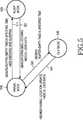
図5は、本発明の実施形態による広帯域無線接続(Broadband Wireless Access;BWA)通信システムの媒体接続制御(Medium Access Control;以下、‘MAC'と称する)階層が支援する動作モードを概略的に示す図である。 FIG. 5 schematically illustrates an operation mode supported by a medium access control (hereinafter referred to as 'MAC') layer of a broadband wireless access (BWA) communication system according to an embodiment of the present invention. FIG.
本発明の実施形態の下記の説明において、本発明のBWA通信システムの一例として、直交周波数分割多元(Orthogonal Frequency Division Multiplexing;以下、‘OFDM'と称する)方式及び直交周波数分割多元接続(Orthogonal Frequency Division Multiple Access;以下、‘OFDMA'と称する)方式によって通信を遂行するIEEE(Institute of Electrical and Electronics Engineers) 802.16e通信システムが適用される。図5を参照すると、上記IEEE802.16e通信システムのMAC階層は、アウェイクモード510と、スリープモード520と、アイドルモード530との3種類の動作モードを支援する。ここで、アウェイクモード510及びスリープモード520は、図2で説明したアウェイクモード210及びスリープモード220と同一であるので、その詳細な説明を省略する。 In the following description of the embodiments of the present invention, as an example of the BWA communication system of the present invention, an Orthogonal Frequency Division Multiplexing (hereinafter referred to as 'OFDM') scheme and an Orthogonal Frequency Division Multiple Access (Orthogonal Frequency Division) An IEEE (Institute of Electrical and Electronics Engineers) 802.16e communication system that performs communication by a multiple access (hereinafter referred to as “OFDMA”) scheme is applied. Referring to FIG. 5, the MAC layer of the IEEE 802.16e communication system supports three types of operation modes: an
アイドルモード530は、本発明の実施形態で新たに提案されたモードである。アイドルモード530に存在する移動加入者端末機(Mobile Subscriber Station;以下、‘MSS'と称する)は、トラヒックの送受信をまったく遂行しない。隣接(neighbor)BSから送信されたダウンリンクプリアンブル、すなわち、パイロット信号の強度を測定し、上記隣接BSからブロードキャストされるシステム情報及び呼出し(paging)メッセージのみを受信するに従って、電力消費の減少効果を極大化させる。すなわち、アイドルモード530に存在するMSSは、非活性化状態(inactive state)に存在し、従って、MSSは、上記非活性化状態で電力及び運営資源(operational resource)を保存するために、現在のモードをアイドルモード530へ変更する。 The
このとき、アイドルモード530に存在するMSSは、現在属しているサービングBS(serving Base Station)のパイロット信号のキャリア対干渉雑音比(Carrier to Interference and Noise Ratio;以下、‘CINR'と称する)が上記隣接BSのうち、特定の隣接BS、すなわち、ターゲットBSのCINR未満となる場合、MSSが上記サービングBSから上記ターゲットBSへ移動したものと判定する。 At this time, the MSS present in the
MSSは、上記ターゲットBSからブロードキャストされるシステム情報(System Information;SI)を分析して、呼出し領域を表示する情報値、すなわち、呼出し領域識別子(Paging Zone Identifier;以下、‘PZID'と称する)を以前のBSのPZIDと比較する。上記比較の結果、以前のBSのPZIDとターゲットBSのPZIDとが相互に異なる場合には、MSSは、位置登録を遂行する。以前のBSのPZIDがターゲットBSのPZIDと同一である場合には、もう一度予め定められた時間の間にスリープ状態を保持する。また、アイドルモード530に存在するMSSは、予め定められた時間が経過すると、位置移動が変更されないとしても、位置登録を遂行して位置情報を更新する。 The MSS analyzes system information (SI) broadcast from the target BS, and displays an information value indicating a calling area, that is, a calling area identifier (hereinafter referred to as 'PZID'). Compare with previous BS PZID. As a result of the comparison, if the PZID of the previous BS and the PZID of the target BS are different from each other, the MSS performs location registration. If the PZID of the previous BS is the same as the PZID of the target BS, the sleep state is held again for a predetermined time. Further, the MSS existing in the
以下、上記呼出し領域について説明する。 Hereinafter, the calling area will be described.
上記呼出し領域は、複数のBSを1つの呼出し単位でグループ化させた領域である。すなわち、複数のBSを1つの呼出し単位でグループ化させて上記呼出し領域に設定し、上記呼出し領域単位でMSSの位置情報を管理する。上記呼出し領域の各々は、PZIDを使用して区分し、BSの各々は、BS自身のPZID値を他のシステム情報とともにフレームごとにブロードキャストする。MSSが現在の呼出し領域から離れて、新たな呼出し領域へ進入した場合、MSSは、上記新たな呼出し領域の該当BSから新たなPZIDを受信する。上記新たな呼出し領域の該当BSから受信されたPZID値と、以前に受信されたPZID値との差は、MSSが以前の呼出し領域から新たな呼出し領域への進入を認識するようにする。ここで、上記PZID値は、ダウンリンクマップ(DL_MAP)メッセージなどに含まれてもよい。 The call area is an area in which a plurality of BSs are grouped in one call unit. That is, a plurality of BSs are grouped in one call unit and set in the call area, and MSS location information is managed in the call area unit. Each of the call areas is partitioned using PZID, and each BS broadcasts its own PZID value along with other system information for each frame. When the MSS leaves the current calling area and enters a new calling area, the MSS receives a new PZID from the corresponding BS in the new calling area. The difference between the PZID value received from the corresponding BS in the new call area and the previously received PZID value allows the MSS to recognize the entry from the previous call area to the new call area. Here, the PZID value may be included in a downlink map (DL_MAP) message or the like.
このように、呼出し領域が変更されたMSSは、上記新たな呼出し領域の該当BSに位置の変更を要求して、新たな位置でネットワークから発生する呼出しに応答することができる。本発明の好ましい実施形態では、上記呼出し領域を複数のセルにグループ化させる場合を一例に挙げて説明する。しかしながら、上記呼出し領域で単一のセルを含むことは、本発明の範囲を外れるものではない。また、単一のセルを含む呼出し領域は、セル間のハンドオーバー動作にも同一に適用されることができる。上述したように、上記呼出し領域の概念が単一のセルのそれと同一の場合、上記呼出し領域の概念は、同一の方式にてセル間のハンドオーバーに適用されることができる。さらに、上記呼出し領域の概念が単一のセルのそれと同一の場合、MSSは、DL_MAPメッセージに含まれているBS IDを用いて、以前のセルから新たなセルへの移動を認識することができる。 As described above, the MSS whose call area has been changed can request the corresponding BS of the new call area to change its position and respond to a call generated from the network at the new position. In a preferred embodiment of the present invention, the case where the call area is grouped into a plurality of cells will be described as an example. However, including a single cell in the paging area does not depart from the scope of the present invention. Also, a paging area including a single cell can be equally applied to a handover operation between cells. As described above, if the concept of the paging area is the same as that of a single cell, the concept of the paging area can be applied to handover between cells in the same manner. Furthermore, if the concept of the paging area is the same as that of a single cell, the MSS can recognize the movement from the previous cell to the new cell using the BS ID included in the DL_MAP message. .
また、アイドルモード530に存在するMSSは、IEEE802.16e通信システムで基本的に常に割り当てられなければならない基本接続識別子(CID)と、第1の管理CIDと、第2の管理CIDのような無線資源をまったく割り当てられず、これによって、無線資源の使用効率性を極大化させる。 In addition, the MSS existing in the
まず、アウェイクモード510からアイドルモード530へモード遷移する過程について説明する。 First, a process of mode transition from the
MSSがアウェイクモード510からアイドルモード530へモード遷移する場合は、BSが強制的にMSSをモード遷移させる場合、あるいは、MSSの要求に従ってモード遷移する場合である。アウェイクモード510に存在するMSSは、BS又はMSSは、予め定められた時間の間データの送受信が存在しないものと予想される時点で、移動アイドルモード遷移要求(mobile idle mode transition request;MOB_IDL_REQ)メッセージを送信し、移動アイドルモード遷移応答(mobile idle mode transition response;MOB_IDL_RSP)メッセージを受信することによって、アイドルモード530へモード遷移する。MSSがアウェイクモード510からアイドルモード530へモード遷移する動作については、下記で詳細に説明する。 The case where the MSS makes a mode transition from the
一方、MSSがアイドルモード530からアウェイクモード510へモード遷移する場合は、矢印541で示されるように、MSSがBSから移動呼出し要求(mobile paging request;MOB_PAG_REQ)メッセージを受信する場合、MSSが送信するデータを有する場合、MSSが現在の呼出し領域から移動する場合、予め定められた時間が経過して位置更新を遂行する場合、あるいは、MSSが移動して新たなBSがアイドルモード530を支援しない場合である。MSSがアイドルモード530からアウェイクモード510へモード遷移する動作については、下記で詳細に説明するので、ここでは、その詳細な説明を省略する。 On the other hand, when the MSS makes a mode transition from the
図5を参照して、本発明の実施形態による広帯域無線接続通信システムのMAC階層が支援する動作モードについて説明した。次いで、図6を参照して、MSSがアウェイクモードからアイドルモードへモード遷移する動作について説明する。 With reference to FIG. 5, the operation mode supported by the MAC layer of the broadband wireless access communication system according to the embodiment of the present invention has been described. Next, with reference to FIG. 6, description will be given of an operation in which the MSS makes a mode transition from the awake mode to the idle mode.
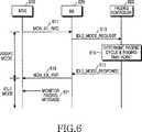
図6は、本発明の実施形態によるMSSのアウェイクモードからアイドルモードへのモード遷移を概略的に示す図である。 FIG. 6 is a diagram schematically illustrating a mode transition from the awake mode to the idle mode of the MSS according to the embodiment of the present invention.
図6を参照すると、まず、MSS610がアウェイクモードに存在している状態で、予め定められた時間の間に、MSSとBS620とのデータの送受信が存在しないと、MSS610は、BS620へMOB_IDL_REQメッセージを送信する(ステップ611)。ここで、上記MOB_IDL_REQメッセージは、MSS610がアイドルモードに滞在する間の選好アイドル周期(PREF_IDLE_INTERVAL)、すなわち、呼出し周期(PAGING CYCLE)に関する情報を含んでよい。これを選好アイドル周期(PREF_IDLE_INTERVAL)、すなわち、選好呼出し周期と称する。上記アイドル周期とは、MSS610が上記アイドルモードに存在する周期を示し、これは、結果的に、MSS610が上記アイドルモードから離れて、BSからの呼出しがあるか否かをモニタリングすべき周期であるので、呼出し周期とも称する。下記の説明では、上記アイドル周期の代わりに、呼出し周期を主に使用するものとする。 Referring to FIG. 6, first, when the
上記MOB_IDL_REQメッセージは、表1に示すような構成を有する。 The MOB_IDL_REQ message has a configuration as shown in Table 1.

表1において、‘管理メッセージタイプ(Management Message Type)’は、現在送信されるメッセージのタイプに関する情報を含む。現在、上記MOB_IDL_REQメッセージの管理メッセージタイプは、まだ決定されていないので、‘??’形態で表記された(Management Message Type=??)。また、‘PREF_IDLE_INTERVAL_INDEX’は、MSSが選好するアイドル周期、すなわち、呼出し周期を示す。 In Table 1, 'Management Message Type' includes information on the type of message currently transmitted. At present, the management message type of the MOB_IDL_REQ message has not yet been determined. ? '(Massage Message Type = ??). Further, 'PREF_IDLE_INTERVAL_INDEX' indicates an idle cycle that is preferred by the MSS, that is, a call cycle.
MSS610から上記MOB_IDL_REQメッセージを受信したBS620は、ステップ630で、呼出し制御器630へアイドルモード要求(IDLE_MODE_REQUEST)メッセージを送信する。BS620から上記IDLE_MODE_REQUESTメッセージを受信した呼出し制御器630は、MSS610のMACアドレスとMSS610の選好呼出し周期とを参照することによって、MSS610に対する呼出し周期を決定する。ここで、呼出し制御器630が決定した呼出し周期を‘選択呼出し周期’と称する。また、ステップ615で、呼出し制御器630は、上記選択呼出し周期に従って、MSS610を呼び出す呼出し時点を決定する。ステップ617で、呼出し制御器630は、上記選択呼出し周期及び上記呼出し時点を含むアイドルモード応答(IDLE_MODE_RESPONSE)メッセージを送信する。 The
上記IDLE_MODE_RESPONSEメッセージを受信したBS620は、ステップ619で、MSS610へ上記選択呼出し周期に関する情報を含んでいるMOB_IDL_RSPメッセージを送信する。また、上記MOB_IDL_RSPメッセージは、下記表2に示すような構成を有する。 In
表2において、‘管理メッセージタイプ’領域は、現在送信されるメッセージのタイプに関する情報を含む。現在、上記MOB_IDL_RSPメッセージの管理メッセージタイプは、まだ決定されていないので、‘??’形態で表記された(Management Message Type=??)。さらに、‘Idle approved’領域は、上記アイドルモードへのモード遷移が承諾されたか否かを示す。上記‘アイドル承諾’領域が‘0'の値を有する場合、上記アイドルモードへのモード遷移が承諾されないことを示し、上記‘アイドル承諾’領域が‘1'の値を有する場合、上記アイドルモードへのモード遷移が承諾されたことを示す。‘After_REQ_action’領域は、MSSが上記MOB_IDL_REQメッセージを再送信しなければならないか否かを示し、‘After_REQ_action’領域が‘0’の値を有する場合、上記MOB_IDL_REQメッセージを再送信しなければならないことを示し、‘After_REQ_action’領域が‘1’の値を有する場合、上記MOB_IDL_REQメッセージを再送信する必要がないことを示す。 In Table 2, the 'management message type' field includes information regarding the type of message currently transmitted. Currently, the management message type of the MOB_IDL_RSP message has not yet been determined. ? '(Massage Message Type = ??). Furthermore, the “Idle applied” area indicates whether or not the mode transition to the idle mode has been approved. If the 'idle acceptance' area has a value of '0', it indicates that the mode transition to the idle mode is not accepted, and if the 'idle acceptance' area has a value of '1', the mode changes to the idle mode. Indicates that the mode transition has been accepted. The 'After_REQ_action' field indicates whether the MSS should retransmit the MOB_IDL_REQ message. If the 'After_REQ_action' field has a value of '0', it indicates that the MOB_IDL_REQ message should be retransmitted. When the “After_REQ_action” field has a value of “1”, it indicates that the MOB_IDL_REQ message does not need to be retransmitted.
‘REQ_duration’領域は、MSSが上記MOB_IDL_REQメッセージを再送信する時点まで待機する時間を示す。‘SEL_IDLE_INTERVAL_INDEX’領域は、呼出し制御器630が決定した選択呼出し周期を示す。‘TB_REGI_REQUIRED’領域は、タイマーに基づく登録を要求するか否かを示し、上記TB_REGI_REQUIRED領域が‘0’の値を有する場合には、上記タイマーに基づく登録を要求しないことを示し、上記TB_REGI_REQUIRED領域が‘1’の値を有する場合には、上記タイマーに基づく登録を要求することを示す。‘TB_REGI_INDEX’領域は、上記タイマーに基づく登録を要求する場合、上記タイマーのカウント値を示す。 The 'REQ_duration' field indicates a time for the MSS to wait until it retransmits the MOB_IDL_REQ message. The 'SEL_IDLE_INTERVAL_INDEX' area indicates a selective call cycle determined by the
MSS610は、BS620から受信されたMOB_IDL_RSPメッセージに含まれている選択呼出し周期を参照して、上記アウェイクモードから上記アイドルモードへモード遷移して、上記選択呼出し周期ごとにMSS610 自身をターゲットとする呼出しメッセージが存在するか否かをモニタリングする(ステップ621)。 The
以下、呼出し制御器630が上記呼出し周期及び上記呼出し時点を決定する動作について説明する。 Hereinafter, an operation in which the
まず、呼出し制御器630は、MSS610のMACアドレスを入力変数にするハッシュ関数(Hash function)を使用して、第1の呼出し時点F0を計算する。また、呼出し制御器630は、上記選択呼出し周期Dを使用して呼出し時点の集合を求める。ここで、上記選択呼出し周期Dは、下記式1のように表現されることができる。First, the
式1において、Dは、呼出し周期を示し、Yは、フレーム番号の最大値を示し、iは、呼出し周期の指数を示し、δ=2jであり、jは、通常、0の値を有する。もちろん、上記jは、0でない他の値を有することができる。In
また、上記呼出し時点の集合を{Fi}(i=0,1,...,Y/D)とする時、(n+1)番目の呼出し時点Fn+1は、n番目の呼出し時点Fn及び下記数2のような関係を有する。When the set of call times is {Fi} (i = 0, 1,..., Y / D), the (n + 1) th call time pointFn + 1 is the nth call time pointFn and the following: The relationship is as shown in Equation 2.
式2に示すように、上記(n+1)番目の呼出し時点Fn+1は、n番目の呼出し時点Fnと上記呼出し周期とを考慮して生成されたオフセットだけ相互に異なって設定される。ここで、FnとFn+1との間の周期(interval)は、呼出し周期である。As shown in Equation 2, the (n + 1) th call time pointFn + 1 is set differently by an offset generated in consideration of thenth call time pointFn and the call cycle. Here, the interval between Fn and Fn + 1 is a calling cycle.
一方、呼出し制御器630が決定した呼出し周期及び呼出し時点に関する情報は、MSS610が属している呼出し領域内のすべてのBSに共有される。 On the other hand, the information regarding the call cycle and call time determined by the
図6では、本発明の実施形態によるMSSがアウェイクモードからアイドルモードへモード遷移する動作について説明した。次いで、図7を参照して、アイドルモードに存在するMSSを呼び出す動作について説明する。 In FIG. 6, the MSS according to the embodiment of the present invention has been described as to the mode transition from the awake mode to the idle mode. Next, with reference to FIG. 7, an operation for calling the MSS existing in the idle mode will be described.
図7は、本発明の実施形態によるアイドルモードに存在するMSSを呼び出す過程の信号フロー図である。 FIG. 7 is a signal flow diagram of a process for calling an MSS existing in an idle mode according to an embodiment of the present invention.
図7を参照すると、まず、呼出し制御器780は、MSS710をターゲットとする呼出しが存在することを感知すると、MSS710が現在属している呼出し領域に該当するすべてのBSへ呼出し要求(PAGING_REQUEST)メッセージを送信する(ステップ711、ステップ713、及びステップ715)。図7では、MSS710が現在属している呼出し領域に、3つのBS、すなわち、第1のBS720、第2のBS740、及び第3のBS760が含まれている場合を仮定したのである。ここで、上記同一の呼出し領域内のすべてのBSへ上記PAGING_REQUESTメッセージを送信する理由は、BSの各々は、MSS710が現在どんなBS領域に存在しているかを認識することができないからである。第1のBS720、第2のBS740、及び第3のBS760の各々は、呼出し制御器780からPAGING_REQUESTメッセージを受信し、MSS710をターゲットとするMOB_PAG_REQメッセージをMSS710へ送信する(ステップ717、ステップ719、及びステップ721)。 Referring to FIG. 7, first, when the call controller 780 detects that there is a call targeting the
ここで、上記MOB_PAG_REQメッセージは、表3に示すような構成を有する。 Here, the MOB_PAG_REQ message has a configuration as shown in Table 3.
表3において、管理メッセージタイプ領域は、現在送信されるメッセージのタイプに関する情報を含む。現在、上記MOB_IDL_REQメッセージの管理メッセージタイプは、まだ決定されていないので、‘??’形態で表記される。‘Number of paged terminal’領域は、上記アイドルモードに存在するMSSのうち、ネットワークが呼び出したMSSの個数を示す。‘MAC_ADDRESS’領域は、呼び出された上記MSSのMACアドレス(すなわち、固有識別子)を示す。ここで、上記呼出しメッセージは、IEEE802.16e通信システムで現在使用されている既存のメッセージを変形して使用することもでき、又は、新たなメッセージを生成して使用することもできる。さらに、‘PAG_PURPOSE’領域は、上記MOB_PAG_REQメッセージを送信する目的を示し、‘LENGTH’領域は、‘PAYLOAD’領域の長さを示し、上記‘PAYLOAD’領域は、上記‘PAG_PURPOSE’領域の値に該当する実際のコンテンツを示す。 In Table 3, the management message type field includes information regarding the type of message currently transmitted. At present, the management message type of the MOB_IDL_REQ message has not yet been determined. ? It is expressed in the form of '. The 'Number of paged terminal' area indicates the number of MSS called by the network among the MSSs present in the idle mode. The 'MAC_ADDRESS' area indicates the MAC address (that is, the unique identifier) of the called MSS. Here, the call message may be used by modifying an existing message currently used in the IEEE 802.16e communication system, or may be used by generating a new message. Further, the 'PAG_PURPOSE' area indicates the purpose of transmitting the MOB_PAG_REQ message, the 'LENGTH' area indicates the length of the 'PAYLOAD' area, and the 'PAYLOAD' area corresponds to the value of the 'PAG_PURPOSE' area. The actual content to be shown.
ここで、上記‘PAG_PURPOSE’領域に記載される値は、表4の通りである。 Here, values described in the 'PAG_PURPOSE' area are as shown in Table 4.
表4において、上記‘00000000’は、未来の使用のために予約された(reserved)値であり、‘00000001’は、上記MOB_PAG_REQメッセージを受信しているMSSがネットワーク再進入及び初期動作を遂行することを示す値であり、‘00000010’は、上記MOB_PAG_REQメッセージを受信しているMSSが上記MOB_PAG_REQメッセージに対する応答メッセージである移動呼出し応答(MOB_PAG_RSP)メッセージを送信する必要がないことを示す値であり、‘00000011’は、上記MOB_PAG_REQメッセージを受信しているMSSが上記MOB_PAG_RSPメッセージを送信しなければならないことを示す値であり、‘00000100’は、呼出し周期を変更しなければならないことを示す値であり、‘00000101’は、位置更新が遂行されなければならないことを示す値であり、‘00000110’乃至‘0xff’は、未来の使用のために予約された値である。 In Table 4, '00000000' is a reserved value for future use, and '00000001' is a network re-entry and initial operation performed by the MSS receiving the MOB_PAG_REQ message. '00000010' is a value indicating that the MSS receiving the MOB_PAG_REQ message does not need to transmit a mobile call response (MOB_PAG_RSP) message that is a response message to the MOB_PAG_REQ message. '00000011' is a value indicating that the MSS receiving the MOB_PAG_REQ message should transmit the MOB_PAG_RSP message, and '00000100' indicates the call cycle. '00000101' is a value indicating that a location update must be performed, and '00000110' through '0xff' are reserved for future use. Value.
また、上記‘PAG_PURPOSE’領域に記載される値に従って、上記‘PAYLOAD’領域に記載されるコンテンツは、表5乃至表9の通りである。 Table 5 to Table 9 show the contents described in the “PAYLOAD” area according to the values described in the “PAG_PURPOSE” area.
表5に記載されているコンテンツは、上記‘PAG_PURPOSE’領域に‘00000001’値が表記されている場合、上記‘PAYLOAD’領域に記載されるコンテンツであって、‘00000000’が上記‘PAG_PURPOSE’領域に表記されると、上記メッセージは、MSSをターゲットとするダウンリンクデータの存在を示すMOB_PAG_REQメッセージであることを示す。 The content described in Table 5 is the content described in the “PAYLOAD” area when “00000001” value is described in the “PAG_PURPOSE” area, and “00000000” is the “PAG_PURPOSE” area. , The message indicates that the message is a MOB_PAG_REQ message indicating the presence of downlink data targeting the MSS.
表6に記載されているコンテンツは、上記‘PAG_PURPOSE’領域に‘00000010’値が表記されている場合、上記‘PAYLOAD’領域に記載されるコンテンツであって、‘00000010’が上記‘PAG_PURPOSE’領域に表記されると、上記メッセージは、MOB_PAG_REQメッセージに対する応答メッセージ、すなわち、MOB_PAG_RSPメッセージの送信を要求しないMOB_PAG_REQメッセージであることを示す。 The content described in Table 6 is the content described in the “PAYLOAD” area when “00000010” value is described in the “PAG_PURPOSE” area, and “00000010” is the “PAG_PURPOSE” area. The message is a response message to the MOB_PAG_REQ message, that is, a MOB_PAG_REQ message that does not require transmission of the MOB_PAG_RSP message.
表7に記載されているコンテンツは、上記‘PAG_PURPOSE’領域に‘00000011’値が表記されている場合、上記‘PAYLOAD’領域に記載されるコンテンツであって、‘00000011’が上記‘PAG_PURPOSE’領域に表記されると、上記メッセージは、MOB_PAG_REQメッセージに対する応答メッセージ、すなわち、MOB_PAG_RSPメッセージの送信を要求するMOB_PAG_REQメッセージであることを示す。 The content described in Table 7 is content described in the “PAYLOAD” area when “00000011” value is described in the “PAG_PURPOSE” area, and “00000011” is the “PAG_PURPOSE” area. The message is a response message to the MOB_PAG_REQ message, that is, a MOB_PAG_REQ message requesting transmission of the MOB_PAG_RSP message.
表8に記載されているコンテンツは、上記‘PAG_PURPOSE’領域に‘00000100’値が表記されている場合、上記‘PAYLOAD’領域に記載されるコンテンツであって、‘00000100’が上記‘PAG_PURPOSE’領域に表記されると、上記メッセージは、呼出し周期の変更を必要とするMOB_PAG_REQメッセージであることを示す。 The content described in Table 8 is the content described in the “PAYLOAD” area when the value “00000100” is described in the “PAG_PURPOSE” area, and “00000100” is the “PAG_PURPOSE” area. , The message indicates that the message is a MOB_PAG_REQ message that requires a change in the call cycle.
表9に記載されているコンテンツは、上記‘PAG_PURPOSE’領域に‘00000101’値が表記されている場合、上記‘PAYLOAD’領域に記載されるコンテンツであって、‘00000101’が上記‘PAG_PURPOSE’領域に表記されると、上記メッセージは、位置更新を必要とするMOB_PAG_REQメッセージであることを示す。 The content described in Table 9 is the content described in the “PAYLOAD” area when the value “00000101” is described in the “PAG_PURPOSE” area, and “00000101” is the “PAG_PURPOSE” area. , The message indicates that the message is a MOB_PAG_REQ message that requires location update.
一方、図7では、上記MOB_PAG_REQメッセージの‘PAG_PURPOSE’領域が上記MOB_PAG_REQメッセージに対する応答メッセージであるMOB_PAG_RSPメッセージの送信を示す値、すなわち、‘00000011’で表記されると仮定する。図10は、上記MOB_PAG_REQメッセージの構成を示す。 On the other hand, in FIG. 7, it is assumed that the 'PAG_PURPOSE' area of the MOB_PAG_REQ message is represented by a value indicating transmission of the MOB_PAG_RSP message that is a response message to the MOB_PAG_REQ message, that is, '00000011'. FIG. 10 shows the structure of the MOB_PAG_REQ message.
表10において、‘管理メッセージタイプ’領域は、現在送信されるメッセージのタイプに関する情報を含む。現在、上記MOB_PAG_RSPメッセージの‘管理メッセージタイプ’は、まだ決定されていないので、‘??’形態で表記された。また、‘Cause’領域は、上記MOB_PAG_RSPメッセージを送信する理由を示す領域であって、上記‘Cause領域’に‘01’値が表記される場合、上記MOB_PAG_REQメッセージが承諾されたことを示す。上記‘Cause’領域に‘10’値が表記される場合、上記MOB_PAG_REQメッセージが拒否されたことを示す。さらに、‘PL_TYPE’領域は、MOB_PAG_RSPメッセージの‘PAYLOAD’のタイプを示す領域であって、上記PL_TYPE領域に‘01’値が表記される場合、上記MOB_PAG_RSPメッセージの‘PAYLOAD’領域に単純な応答が表記されることを示し、上記PL_TYPE領域に‘10’値が表記される場合、上記MOB_PAG_RSPメッセージの‘PAYLOAD’領域に応答メッセージが表記されることを示す。また、‘LENGTH’領域は、‘PAYLOAD’領域の長さを示す領域である。 In Table 10, the 'management message type' field includes information regarding the type of message currently transmitted. Currently, the 'management message type' of the MOB_PAG_RSP message has not been determined yet, so '? ? It was written in the form '. The 'Cause' area indicates the reason for transmitting the MOB_PAG_RSP message. When the 'Cause area' is indicated with a '01' value, it indicates that the MOB_PAG_REQ message has been accepted. When a “10” value is written in the “Cause” area, it indicates that the MOB_PAG_REQ message is rejected. Furthermore, the 'PL_TYPE' field indicates the type of 'PAYLOAD' in the MOB_PAG_RSP message. When the '01' value is written in the PL_TYPE field, a simple response is received in the 'PAYLOAD' field of the MOB_PAG_RSP message. When a “10” value is written in the PL_TYPE area, it indicates that a response message is written in the “PAYLOAD” area of the MOB_PAG_RSP message. The 'LENGTH' region is a region indicating the length of the 'PAYLOAD' region.
一方、上記MOB_PAG_REQメッセージを受信したMSS710は、上記MOB_PAG_REQメッセージの‘PAG_PURPOSE’領域に‘00000011’の値が表記されているので、上記MOB_PAG_REQメッセージに対する応答メッセージであるMOB_PAG_RSPメッセージを該当BSへ送信しなければならないことを認識する。ここで、MSS710が上記アイドルモードへモード遷移する前に、属していたBSから上記呼出し領域内のBSとは異なる他のBSへ移動した場合、MSS710は、さらに初期レンジング動作を遂行しなければならない(ステップ723)。すなわち、MSS710が上記MOB_PAG_RSPメッセージを送信するためには、アップリンク帯域幅が割り当てられなければならないので、MSS710は、初期レンジングを遂行する。図7は、MSS710が初期レンジングを遂行した結果、第1のBS720をMSS710自身が現在属しているサービングBSと判断したものと仮定する。 On the other hand, the
その後、MSS710は、第1のBS720へ上記MOB_PAG_RSPメッセージを送信し(ステップ725)、MSS710から上記MOB_PAG_RSPメッセージを受信した第1のBS720は、上記‘PAGING_REQUEST’メッセージに対する応答メッセージである‘呼出し応答(PAGING_RESPONSE)メッセージを呼出し制御器780へ送信する(ステップ727)。さらに、第1のBS720は、MSS710へMOB_IDL_RSPメッセージを送信し、これによって、MSS710がアイドルモードへモード遷移するように制御する(ステップ729)。 After that, the
図7では、本発明の実施形態によるアイドルモードに存在するMSSを呼び出す動作について説明した。次いで、図8を参照して、本発明の実施形態による位置更新を要求しないアイドルモードに存在するMSSのハンドオーバー動作について説明する。 In FIG. 7, the operation of calling the MSS existing in the idle mode according to the embodiment of the present invention has been described. Next, a handover operation of the MSS existing in the idle mode that does not require a location update according to an embodiment of the present invention will be described with reference to FIG.
図8は、本発明の実施形態による位置更新を要求しないアイドルモードに存在するMSSのハンドオーバー過程を概略的に示す信号フロー図である。 FIG. 8 is a signal flow diagram schematically illustrating a handover process of an MSS existing in an idle mode that does not require a location update according to an embodiment of the present invention.
図8は、アイドルモードに存在するMSS810が同一の呼出し領域、すなわち、同一のPZIDを使用する呼出し領域内へ位置を移動した場合、すなわち、ハンドオーバーを遂行する場合に基づいて説明する。図8を参照すると、まず、サービングBS830は、MSS810へMOB_IDL_RSPメッセージを送信する(ステップ811)。サービングBS830は、MOB_IDL_REQメッセージに応じてMOB_IDL_RSPを送信してよく、それとも、サービングBS830がunsolicited方式に基づいてMOB_IDL_RSPメッセージを送信してよい。ここで、サービングBS830がunsolicited方式に基づいてMOB_IDL_RSPメッセージを送信する場合は、サービングBS830の負荷を調整するための場合となることができる。サービングBS830から上記MOB_IDL_RSPメッセージを受信したMSS810は、アウェイクモードからアイドルモードへ遷移する。 FIG. 8 will be described based on the case where the
一方、MSS810がアイドルモードに存在する間に、サービングBS830が管理するサービス領域からターゲットBS850が管理する他のサービス領域へ位置を移動する(ステップ813)。ここで、サービングBS830及びターゲットBS850は、同一の呼出し領域内に存在すると仮定する。 On the other hand, while the
MSS810が移動すると、サービングBS830とMSS810との間の通信が接続されていないので、MSS810が呼出し時点で覚めてモニタリングするとしても、MOB_PAG_REQメッセージを受信することができない。従って、MSS810が新たなBS(すなわち、ターゲットBS850)へ移動すると、MSSは、ターゲットBS850がブロードキャストしたDL_MAPメッセージ、UL_MAPメッセージ、ダウンリンクチャンネルディスクリプタ(Downlink Channel Descriptor;以下、‘DCD'と称する)メッセージ、アップリンクチャンネルディスクリプタ(Uplink Channel Descriptor;以下、‘UCD'と称する)メッセージからターゲットBS850の情報を受信する(ステップ815)。上述したように、ターゲットBS850のPZIDは、上記DL_MAPメッセージに含まれてよい。 When the
このように、ターゲットBS850がブロードキャストしたBS情報を受信したMSS810は、ターゲットBS850のPZIDを認識し、従って、サービングBS830及びターゲットBS850が、同一の呼出し領域内に存在することを認識する(ステップ817)。ターゲットBS850がサービングBS830と同一の呼出し領域に存在していると判断されると、MSS810は、フレーム番号を確認して、MSS810自身の呼出し時点を確認する。その後、MSS810は、上記呼出し時点に到達したか否かを検査する(ステップ819)。上記検査の結果、上記呼出し時点に到達しなかった場合、MSS810は、隣接BSをスキャニングする(ステップ821)。ここで、MSS810が上記隣接BSから送信されたパイロット信号のCINRをスキャニングする理由は、上記アイドルモードでの位置移動を検出するためである。 In this way, the
一方、上記検査の結果、上記呼出し時点に到達した場合、MSS810は、上記アイドルモードから覚めて、ターゲットBS850からMOB_PAG_REQメッセージを受信する(ステップ823)。ここで、ターゲットBS850から送信されたMOB_PAG_REQメッセージは、MSS810のMACアドレスを含んでいないと仮定し、これに従って、MSS810は、上記アイドルモードにそのまま存在する。 On the other hand, when the call time is reached as a result of the check, the
図8では、本発明の実施形態による位置更新を必要としないアイドルモードに存在するMSSのハンドオーバー動作について説明した。次いで、図9を参照して、本発明の実施形態による位置更新を必要とするアイドルモードに存在するMSSのハンドオーバー動作について説明する。 In FIG. 8, the handover operation of the MSS existing in the idle mode that does not require location update according to the embodiment of the present invention has been described. Next, a handover operation of an MSS existing in an idle mode that requires location update according to an embodiment of the present invention will be described with reference to FIG.
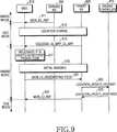
図9は、本発明の実施形態による位置更新が必要とされるアイドルモードに存在するMSSのハンドオーバー過程を概略的に示す信号フロー図である。 FIG. 9 is a signal flow diagram schematically illustrating a handover process of an MSS existing in an idle mode where a location update is required according to an embodiment of the present invention.
図9は、アイドルモードに存在するMSS910が相互に異なる呼出し領域、すなわち、相異なるPZIDを使用する呼出し領域へ位置を移動した場合、すなわち、ハンドオーバーを遂行した場合を説明する。図9を参照すると、まず、サービングBS930は、MSS910へMOB_IDL_RSPメッセージを送信する(ステップ911)。サービングBS930は、MSS910から送信されたMOB_IDL_REQメッセージに応じてMOB_IDL_RSPを送信してよく、それとも、サービングBS930がunsolicited方式に基づいてMOB_IDL_RSPメッセージを送信してよい。ここで、サービングBS930がunsolicited方式に基づいてMOB_IDL_RSPメッセージを送信する場合は、サービングBS930の負荷を調整するための場合となることができる。サービングBS930から上記MOB_IDL_RSPメッセージを受信したMSS910は、アウェイクモードからアイドルモードへ遷移する。 FIG. 9 illustrates a case where the
一方、MSS910がアイドルモードに存在する間に、サービングBS930が管理するサービス領域からターゲットBS950が管理する他のサービス領域へ位置を移動する(ステップ913)。ここで、サービングBS930及びターゲットBS950は、相互に異なる呼出し領域内に存在すると仮定する。MSS910が移動すると、サービングBS930とMSS910との間の通信が接続されていないので、MSS910が呼出し時点で覚めてモニタリングするとしても、MOB_PAG_REQメッセージを受信することができない。従って、MSS910が新たなBS(すなわち、ターゲットBS950)へ移動すると、MSSは、ターゲットBS950がブロードキャストしたDL_MAPメッセージ、UL_MAPメッセージ、DCDメッセージ、及びUCDメッセージからターゲットBS950の情報を受信する(ステップ915)。上述したように、ターゲットBS950のPZIDは、上記DL_MAPメッセージに含まれてよい。 On the other hand, while the
このように、ターゲットBS950がブロードキャストしたBS情報を受信したMSS910は、ターゲットBS950のPZIDを認識し、従って、サービングBS930及びターゲットBS950が、相互に異なる呼出し領域内に存在することを認識する(ステップ917)。ターゲットBS950がサービングBS930と相互に異なる呼出し領域に存在していると判断されると、MSS910は、初期レンジング動作を遂行する(ステップ919)。上記初期レンジング動作を遂行すると、MSS910は、基本CID及び第1の管理CIDを獲得する。すると、MSS910は、上記初期レンジング動作を通じて獲得した第1の管理CIDを使用して、ターゲットBS950へ移動位置更新要求(Location Update Request;MOB_LU_REQ)メッセージを送信する(ステップ921)。ここで、上記MOB_LU_REQメッセージは、表11に示すような構成を有する。 In this way, the
表11において、‘管理メッセージタイプ’領域は、現在送信されるメッセージのタイプに関する情報を含む。現在、上記MOB_LU_REQメッセージの‘管理メッセージタイプ’は、まだ決定されていないので、‘??’形態で表記された(Management Message Type=??)。また、‘PREF_IDLE_INTERVAL_INDEX’は、MSS910が選好するアイドル区間(すなわち、呼出し周期)を示し、‘PREF_PZONE_ID’は、MSS910が上記MOB_LU_REQメッセージを送信する前に属していた、すなわち、MSS910がハンドオーバーする前に属していたサービングBS930のPZIDを示す。 In Table 11, the 'management message type' field includes information regarding the type of message currently transmitted. Currently, the “management message type” of the MOB_LU_REQ message has not been determined yet, so “? ? '(Massage Message Type = ??). Also, 'PREF_IDLE_INTERVAL_INDEX' indicates an idle period (that is, a call cycle) that
一方、MSS910から上記MOB_LU_REQメッセージを受信したターゲットBS950は、呼出し制御器970へ位置更新要求(LOCATION_UPDATE_REQUEST)メッセージを送信する(ステップ923)。ここで、ターゲットBS950から送信されたLOCATION_UPDATE_REQUESTメッセージは、上記位置更新を要求するMSS910のMACアドレス及びMSS910がハンドオーバーの前に属していたサービングBS930のPZIDを含む。上記LOCATION_UPDATE_REQUESTメッセージを受信した呼出し制御器970は、上記LOCATION_UPDATE_REQUESTメッセージに含まれているPZID及びMACアドレスに基づいて、MSS910の位置を更新した後、上記LOCATION_UPDATE_REQUESTメッセージに対する応答メッセージである位置更新応答(LOCATION_UPDATE_RESPONSE)メッセージをターゲットBS950へ送信する(ステップ925)。呼出し制御器970から上記LOCATION_UPDATE_ RESPONSEメッセージを受信したターゲットBS950は、MSS910へ移動位置更新応答(MOB_LU_RSP)メッセージを送信する(ステップ927)。ここで、上記MOB_LU_RSPメッセージは、表12に示すような構成を有する。 On the other hand, the
表12において、‘管理メッセージタイプ’領域は、現在送信されるメッセージのタイプに関する情報を含む。現在、上記MOB_LU_RSPメッセージの‘管理メッセージタイプ’は、まだ決定されていないので、‘??’形態で表記された(Management Message Type=??)。さらに、‘LU approved’領域は、位置更新が失敗したか否かを示す。上記‘LU approved’領域に‘0’の値が表記されると、位置更新が失敗したことを示し、上記‘LU approved’領域に‘1’の値が表記されると、位置更新が成功したことを示す。また、‘After_REQ_action’領域は、上記位置更新が失敗した場合、すなわち、上記LU approved領域に‘0’の値が表記される場合、MSSが上記MOB_LU_REQメッセージを再送信しなければならないか否かを示す領域であって、上記‘After_REQ_action’領域に‘0’の値が表記される場合には、予め定められた時間を待機した後、上記MOB_LU_REQメッセージを再送信しなければならないことを示し、上記‘After_REQ_action’領域に‘1’の値が表記される場合には、上記MOB_LU_REQメッセージを再送信する必要がないことを示す。また、‘REQ_duration’領域は、上記MOB_LU_REQメッセージを再送信するために待機しなければならない時間を示す。‘SEL_IDLE_INTERVAL_INDEX’領域は、上記位置更新が成功した場合、新たに決定された呼出し周期を示す。‘TB_REGI_REQUIRED’領域は、新たなBS、すなわち、ターゲットBSがタイマーに基づく登録を要求するか否かを示す。‘TB_REGI_INDEX’領域は、上記タイマーに基づく登録を要求する場合、上記タイマーのカウント値を示す。 In Table 12, the 'management message type' field includes information regarding the type of message currently transmitted. At present, the 'management message type' of the MOB_LU_RSP message has not been determined yet, so '? ? '(Massage Message Type = ??). Furthermore, the 'LU applied' area indicates whether or not the location update has failed. If a value of “0” is written in the “LU applied” area, it indicates that the location update has failed, and if a value of “1” is written in the “LU applied” area, the location update is successful. It shows that. Also, the 'After_REQ_action' area indicates whether or not the MSS should retransmit the MOB_LU_REQ message when the location update fails, that is, when a value of '0' is written in the LU applied area. When a value of “0” is written in the “After_REQ_action” area, it indicates that the MOB_LU_REQ message must be retransmitted after waiting for a predetermined time, When a value of “1” is written in the “After_REQ_action” area, it indicates that it is not necessary to retransmit the MOB_LU_REQ message. The 'REQ_duration' area indicates a time that must be waited for resending the MOB_LU_REQ message. The 'SEL_IDLE_INTERVAL_INDEX' area indicates a newly determined call cycle when the location update is successful. The 'TB_REGI_REQUIRED' field indicates whether a new BS, ie, the target BS, requests registration based on a timer. The 'TB_REGI_INDEX' area indicates the count value of the timer when registration based on the timer is requested.
一方、MSS910は、ターゲットBS950から上記MOB_LU_RSPメッセージを受信すると、上記MOB_LU_RSPメッセージに含まれている選択呼出し周期に対応するように、上記アイドルモードへスイッチングするか、又はモード遷移する。 On the other hand, when receiving the MOB_LU_RSP message from the
図9では、本発明の実施形態による位置更新が必要とされるアイドルモードに存在するMSSのハンドオーバー動作について説明した。次いで、図10を参照して、本発明の実施形態によるアイドルモードに存在するMSSの周期的な位置更新動作について説明する。 In FIG. 9, the handover operation of the MSS existing in the idle mode where the location update is required according to the embodiment of the present invention has been described. Next, the periodic location update operation of the MSS existing in the idle mode according to the embodiment of the present invention will be described with reference to FIG.
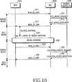
図10は、本発明の実施形態によるアイドルモードに存在するMSSの周期的な位置更新に対する過程を概略的に示す信号フロー図である。 FIG. 10 is a signal flow diagram schematically illustrating a process for periodic location update of an MSS existing in an idle mode according to an embodiment of the present invention.
図10を参照すると、まず、アウェイクモードに存在するMSS1010は、BS1030へMOB_IDL_REQメッセージを送信する(ステップ1011)。MSS1010から上記MOB_IDL_REQメッセージを受信したBS1030は、呼出し制御器1050へIDLE_MODE_REQUESTメッセージを送信する(ステップ1013)。上記IDLE_MODE_REQUESTメッセージを受信した呼出し制御器1050は、BS1030へ上記IDLE_MODE_REQUESTメッセージに対する応答メッセージであるIDLE_MODE_RESPONSEメッセージを送信する(ステップ1015)。上記IDLE_MODE_RESPONSEメッセージを受信したBS1030は、MSS1010へ上記MOB_IDL_REQメッセージに対する応答メッセージであるMOB_IDL_RSPメッセージを送信する(ステップ1017)。ここで、上記MOB_IDL_RSPメッセージは、MSS1010に対して決定された選択呼出し周期及び呼出し時点、そして、タイマーに基づく登録に対する要求を示す情報を含む。すなわち、上記MOB_IDL_REQメッセージの‘TB_REGI_REQUIRED’領域の値が‘1’で表記されると仮定する。 Referring to FIG. 10, first, the
BS1030から上記MOB_IDL_RSPメッセージを受信したMSS1010は、上記アウェイクモードから上記アイドルモードへスイッチングするか、又はモード遷移する。一方、MSS1010は、上記アイドルモードで、上記タイマーに基づく登録を要求するために、予め定められた時間‘TB_REGI_INTERVAL’のカウントを開始し、上記‘TB_REGI_INTERVAL’に到達すると(ステップ1019)、位置更新のために初期レンジングを遂行する(ステップ1021)。上記初期レンジング動作を遂行すると、MSS1010は、基本CID及び第1の管理CIDを獲得する。すると、MSS1010は、BS1030へMOB_LU_REQメッセージを送信する(ステップ1023)。図10のステップ1023乃至ステップ1029までの動作は、図9で説明した、MSS910及びターゲットBS950と、呼出し制御器970との間で遂行されるステップ921乃至ステップ927までの動作と類似しているので、ここでは、その詳細な説明を省略する。 The
次いで、MSS910が上記‘TB_REGI_INTERVAL’を決定する過程について説明する。 Next, a process in which the
まず、MSS910は、MOB_IDL_RSPメッセージの‘SEL_IDLE_INTERVAL_INDEX’値及び‘TB_REGI_INDEX’値を使用して、‘TB_REGI_INTERVAL’を求める。ここで、‘TB_REGI_INTERVAL’は、下記式3のように表現されることができる。 First, the
式3において、iは、‘SEL_IDLE_INTERVAL_INDEX’を示し、Tは、‘TB_REGI_INDEX’を示す。すなわち、‘TB_REGI_INTERVAL’は、上記呼出し周期の整数倍で表現されることができる。 In Expression 3, i represents ‘SEL_IDLE_INTERVAL_INDEX’, and T represents ‘TB_REGI_INDEX’. That is, 'TB_REGI_INTERVAL' can be expressed by an integral multiple of the call period.
MSSの位置更新を周期的に遂行する理由は、位置更新の便宜を増加させるだけではなく、MSSの位置に対する信頼性も高める。もちろん、図10を参照して説明したように、周期的に位置更新を遂行する場合、MSSが存在している領域が実際に変更されない場合でも、位置更新を遂行することもある。しかしながら、上記呼出し制御器は、MSSがもっとも最近に位置を更新したセルから始めて呼出し領域を拡張していきつつ呼び出す場合、上記周期的な位置更新によるロードの増加を呼出し領域の縮小によるロードの減少とマッチングさせることができる。 The reason for periodically performing the location update of the MSS not only increases the convenience of location update, but also increases the reliability of the location of the MSS. Of course, as described with reference to FIG. 10, when the location update is performed periodically, the location update may be performed even if the region where the MSS exists is not actually changed. However, when the call controller starts calling from the cell in which the MSS has most recently updated the position and expands the call area, the call controller increases the load due to the periodic position update and decreases the load by reducing the call area. Can be matched.
以上、本発明の詳細について具体的な実施形態に基づき説明してきたが、本発明の範囲を逸脱しない限り、各種の変形が可能なのは明らかである。従って、本発明の範囲は、上記実施形態に限定されるものではなく、特許請求の範囲の記載及び該記載と同等なものにより定められるべきである。 Although the details of the present invention have been described above based on the specific embodiments, it is apparent that various modifications can be made without departing from the scope of the present invention. Therefore, the scope of the present invention should not be limited to the above-described embodiment, but should be determined by the description of the claims and the equivalents thereof.
510 アウェイクモード
520 スリープモード
530 アイドルモード
510
Claims (37)
Translated fromJapanese前記移動加入者端末機が非活性化状態(inactive state)に存在する場合、アイドルモードへモード遷移するステップと、
前記アイドルモードで、前記移動加入者端末機のサービング基地局が属している呼出し領域とは異なる呼出し領域に属しているターゲット基地局への前記移動加入者端末機の移動を検出するステップと、
前記移動加入者端末機の移動が検出されたことに基づき、アウェイクモードへモード遷移して前記ターゲット基地局とともに位置更新を遂行するステップと、
前記アイドルモードで、前記移動加入者端末機が前記移動加入者端末機自身をターゲットとする呼出しを感知すると、前記アイドルモードから前記アウェイクモードへモード遷移するステップと、
を具備し、
前記位置更新は、前記ターゲット基地局へ位置更新要求を送信するとともに、前記ターゲット基地局から位置更新応答を受信することによって実行され、
前記呼出しを感知することは、前記ターゲット基地局からブロードキャストされる呼出し情報を呼出し周期に対応して受信するとともに、前記呼出し情報が前記移動加入者端末機の移動加入者端末機識別子を含む場合、前記呼出しの存在を認識することによって実行することを特徴とする方法。A method for controlling a mobile subscriber station in a communication system, comprising:
When the mobile subscriber station is in an inactive state, transitioning to an idle mode; and
Detecting, in the idle mode, movement of the mobile subscriber station to a target base station belonging to a call area different from a call area to which a serving base station of the mobile subscriber terminal belongs;
Based on the detected movement of the mobile subscriber station, performing a mode transition to the awake mode and performing location update together with the target base station;
In the idle mode, when the mobile subscriber station detects a call targeting the mobile subscriber terminal itself, the mode transition from the idle mode to the awake mode;
Comprising
The location update is performed by transmitting a location update request to the target base station and receiving a location update response from the target base station,
Detecting the call includes receiving call information broadcast from thetarget base station corresponding to a call cycle, and the call information includes a mobile subscriber station identifier of the mobile subscriber station, Performing by recognizing the presence of said call.
前記アウェイクモードは、IEEE802.16e通信システムのアウェイクモードと同一の動作を実行するモードであって、前記移動加入者端末機と前記サービング基地局との間でパケットデータが送受される動作が実行されるモードであり、
前記スリープモードは、IEEE802.16e通信システムのスリープモードと同一の動作を実行するモードであって、前記移動加入者端末機と前記サービング基地局との間で前記パケットデータが送受される動作が実行されないモードであり、
前記移動加入者端末機が前記アウェイクモードから前記スリープモードへモード遷移するために、前記移動加入者端末機は前記サービング基地局からモード遷移の承諾を受信し、
前記アイドルモードでは、少なくとも1つの基地局から送信されたパイロット信号とシステム情報と呼出しメッセージを前記移動加入者端末機が受信するとともに、前記システム情報に含まれている呼出し領域を表示する情報に基づいて前記移動加入者端末機の移動を検出することを特徴とする請求項1記載の方法。The operation mode of the medium connection control layer in the communication system has the awake mode, the idle mode, and a sleep mode,
The awake mode is a mode that performs the same operation as the awake mode of the IEEE 802.16e communication system, and an operation in which packet data is transmitted and received between the mobile subscriber station and the serving base station is performed. Mode,
The sleep mode is a mode in which the same operation as the sleep mode of the IEEE 802.16e communication system is executed, and an operation in which the packet data is transmitted and received between the mobile subscriber station and the serving base station is executed. Mode that is not
In order for the mobile subscriber station to transition from the awake mode to the sleep mode, the mobile subscriber station receives an acknowledgment of mode transition from the serving base station, and
In the idle mode, the mobile subscriber station receives a pilot signal, system information and a call message transmitted fromat least one base station, and based on information indicating a call area included in the system information. 2. The method of claim 1, further comprising detecting movement of the mobile subscriber station.
アウェイクモードで、予め定められた第1の時間の間に、サービング基地局と前記移動加入者端末機との間のデータ送信が存在しない場合、アイドルモードへモード遷移するステップと、
前記アイドルモードで、前記移動加入者端末機のサービング基地局が属している呼出し領域とは異なる呼出し領域に属しているターゲット基地局への前記移動加入者端末機の移動を検出するステップと、
前記アイドルモードで、予め定められたアイドル期間で周期的に前記アウェイクモードへモード遷移して、位置更新動作を遂行するステップと
を具備し、
前記位置更新動作を遂行するステップでは、前記予め定められたアイドル期間及びオフセット値に基づいて決定されたタイミングで前記移動加入者端末機を前記アウェイクモードへモード遷移し、
前記オフセット値は、前記ターゲット基地局の移動加入者端末機が前記アイドルモードから前記アウェイクモードへモード遷移する時点を相互に異なって設定するために決定されており、
前記位置更新は、前記ターゲット基地局へ位置更新要求を送信するとともに、前記ターゲット基地局から位置更新応答を受信することによって実行されることを特徴とする方法。A method for controlling a mobile subscriber station in a communication system, comprising:
In the awake mode, when there is no data transmission between the serving base station and the mobile subscriber station during a predetermined first time, the mode transition to the idle mode;
Detecting, in the idle mode, movement of the mobile subscriber station to a target base station belonging to a call area different from a call area to which a serving base station of the mobile subscriber terminal belongs;
In the idle mode, periodically changing to the awake mode in a predetermined idle period, and performing a position update operation,
In the step of performing the location update operation, the mobile subscriber station is shifted to the awake mode at a timing determined based on the predetermined idle period and an offset value,
The offset value is determined to set different time points when the mobile subscriber station of thetarget base station makes a mode transition from the idle mode to the awake mode.
The location update is performed by transmitting a location update request to the target base station and receiving a location update response from the target base station.
前記アウェイクモードは、IEEE802.16e通信システムのアウェイクモードと同一の動作を実行するモードであって、前記移動加入者端末機と前記サービング基地局との間でパケットデータが送受される動作が実行されるモードであり、
前記スリープモードは、IEEE802.16e通信システムのスリープモードと同一の動作を実行するモードであって、前記移動加入者端末機と前記サービング基地局との間で前記パケットデータが送受される動作が実行されないモードであり、
前記移動加入者端末機が前記アウェイクモードから前記スリープモードへモード遷移するために、前記移動加入者端末機は前記サービング基地局からモード遷移の承諾を受信し、
前記アイドルモードでは、少なくとも1つの基地局から送信されたパイロット信号とシステム情報と呼出しメッセージを前記移動加入者端末機が受信するとともに、前記システム情報に含まれている呼出し領域を表示する情報に基づいて前記移動加入者端末機の移動を検出することを特徴とする請求項6記載の方法。The operation mode of the medium connection control layer in the communication system has the awake mode, the idle mode, and a sleep mode,
The awake mode is a mode that performs the same operation as the awake mode of the IEEE 802.16e communication system, and an operation in which packet data is transmitted and received between the mobile subscriber station and the serving base station is performed. Mode,
The sleep mode is a mode in which the same operation as the sleep mode of the IEEE 802.16e communication system is executed, and an operation in which the packet data is transmitted and received between the mobile subscriber station and the serving base station is executed. Mode that is not
In order for the mobile subscriber station to transition from the awake mode to the sleep mode, the mobile subscriber station receives an acknowledgment of mode transition from the serving base station, and
In the idle mode, the mobile subscriber station receives a pilot signal, system information and a call message transmitted fromat least one base station, and based on information indicating a call area included in the system information. The method of claim 6, further comprising detecting movement of the mobile subscriber station.
呼出し周期に従って、前記サービング基地局からブロードキャストされる呼出し情報を受信し、前記呼出し情報が前記移動加入者端末機の移動加入者端末機識別子を含む場合、前記呼出しの存在を認識することを特徴とする請求項9記載の方法。The step of sensing the call comprises:
Receiving call information broadcast from the serving base station according to a call cycle, and recognizing the presence of the call when the call information includes a mobile subscriber station identifier of the mobile subscriber station. The method according to claim 9.
呼出し周期を決定するステップと、
前記複数の移動加入者端末機が覚める呼出し時点を相互に異なって設定するためのオフセット値を決定するステップと、
前記呼出し周期及び前記オフセット値に基づいて、前記呼出し時点を決定するステップと、
前記移動加入者端末機が前記移動加入者端末機自身をターゲットとするサービング基地局からの呼出しを感知すると、前記移動加入者端末機が前記アイドルモードから前記アウェイクモードへモード遷移するとともに、前記サービング基地局の呼出し領域から該サービング基地局の呼出し領域とは異なる呼出し領域への前記移動加入者端末機の移動が検出されたことに基づき前記ターゲット基地局とともに前記移動加入者端末機が位置更新を遂行するステップと、
を具備し、
前記位置更新を遂行するステップは、前記ターゲット基地局へ位置更新要求を送信するとともに、前記ターゲット基地局から位置更新応答を受信するステップをさらに具備することを特徴とする方法。A method for controlling a plurality of operation modes of a mobile subscriber station by a communication system, comprising:
Determining a call cycle;
Determining an offset value for setting different call times at which the plurality of mobile subscriber stations wake up;
Determining the call time based on the call period and the offset value;
When the mobile subscriberstation senses a callfrom aserving base station targeting the mobile subscriber station itself, the mobile subscriberstation transitions from the idle mode to the awake mode, and theservingthe mobile subscriber station location update together with the target base station based on the movement of the mobile subscriber station to a different calling area is detectedfrom the calling area of the base station and the calling area ofthe serving base station Carrying out the steps,
Comprising
Perform preSymbol position location updating step, the sends a location updating request to the target base station, wherein the further comprising the step of receiving a location update response from the target base station.
前記アウェイクモードは、IEEE802.16e通信システムのアウェイクモードと同一の動作を実行するモードであって、前記移動加入者端末機と前記サービング基地局との間でパケットデータが送受される動作が実行されるモードであり、
前記スリープモードは、IEEE802.16e通信システムのスリープモードと同一の動作を実行するモードであって、前記移動加入者端末機と前記サービング基地局との間で前記パケットデータが送受される動作が実行されないモードであり、
前記移動加入者端末機が前記アウェイクモードから前記スリープモードへモード遷移するために、前記移動加入者端末機は前記サービング基地局からモード遷移の承諾を受信し、
前記アイドルモードでは、少なくとも1つの基地局から送信されたパイロット信号とシステム情報と呼出しメッセージを前記移動加入者端末機が受信するとともに、前記システム情報に含まれている呼出し領域を表示する情報に基づいて前記移動加入者端末機の移動を検出することを特徴とする請求項11記載の方法。The operation mode of the medium connection control layer in the communication system has the awake mode, the idle mode, and a sleep mode,
The awake mode is a mode that performs the same operation as the awake mode of the IEEE 802.16e communication system, and an operation in which packet data is transmitted and received between the mobile subscriber station and the serving base station is performed. Mode,
The sleep mode is a mode in which the same operation as the sleep mode of the IEEE 802.16e communication system is executed, and an operation in which the packet data is transmitted and received between the mobile subscriber station and the serving base station is executed. Mode that is not
In order for the mobile subscriber station to transition from the awake mode to the sleep mode, the mobile subscriber station receives an acknowledgment of mode transition from the serving base station, and
In the idle mode, the mobile subscriber station receives a pilot signal, system information and a call message transmitted fromat least one base station, and based on information indicating a call area included in the system information. The method of claim11, further comprising detecting movement of the mobile subscriber station.
前記呼出し周期に従って、前記移動加入者端末機の前記サービング基地局からブロードキャストされる呼出し情報を受信するステップと、
前記呼出し情報が前記移動加入者端末機の移動加入者端末機識別子を含む場合、前記呼出しの存在を認識するステップと
を具備することを特徴とする請求項11記載の方法。The step of sensing the call comprises:
According to the call period, receiving a call information broadcast fromthe serving base station of the mobile subscriber station,
The method of claim11 , further comprising the step of recognizing the presence of the call if the call information includes a mobile subscriber station identifier of the mobile subscriber station.
アウェイクモードで予め設定されている第1の時間の間に、前記サービング基地局と前記移動加入者端末機との間のデータ送信が存在しない場合、アイドルモードへモード遷移し、前記アイドルモードで、前記サービング基地局が属している呼出し領域と相互に異なる呼出し領域に属しているターゲット基地局で前記移動加入者端末機の移動を検出すると、前記アウェイクモードへモード遷移して、前記ターゲット基地局に前記移動加入者端末機の移動による位置更新を要求し、前記ターゲット基地局から前記位置更新の要求に応じて受信された位置更新応答に対応して位置更新動作を遂行する前記移動加入者端末機と、
前記移動加入者端末機からの位置更新要求を検出すると、前記呼出し領域を管理する呼出し制御器及び前記移動加入者端末機の位置更新動作を遂行して、前記移動加入者端末機へ前記位置更新応答を送信する前記ターゲット基地局と、
前記ターゲット基地局及び前記移動加入者端末機の位置更新動作の結果に対応して前記移動加入者端末機の位置を更新する前記呼出し制御器と
を具備することを特徴とするシステム。In a broadband wireless access communication system having a mobile subscriber station and a serving base station providing a service to the mobile subscriber station, the mobile subscriber station controls an operation mode of a medium connection control layer A system,
If there is no data transmission between the serving base station and the mobile subscriber station during a first time preset in the awake mode, the mode transitions to the idle mode, and in the idle mode, When a movement of the mobile subscriber station is detected in a target base station belonging to a call area different from a call area to which the serving base station belongs, a mode transition is made to the awake mode, and the target base station The mobile subscriber station that requests a location update due to movement of the mobile subscriber station and performs a location update operation in response to a location update response received in response to the location update request from the target base station. When,
Upon detecting a location update request from the mobile subscriber station, the location update operation of the call controller for managing the call area and the location of the mobile subscriber station is performed, and the location update is performed to the mobile subscriber station. The target base station transmitting a response;
The call controller for updating the position of the mobile subscriber station in response to the result of the location update operation of the target base station and the mobile subscriber station.
前記アウェイクモードは、IEEE802.16e通信システムのアウェイクモードと同一の動作を実行するモードであって、前記移動加入者端末機と前記サービング基地局との間でパケットデータが送受される動作が実行されるモードであり、
前記スリープモードは、IEEE802.16e通信システムのスリープモードと同一の動作を実行するモードであって、前記移動加入者端末機と前記サービング基地局との間で前記パケットデータが送受される動作が実行されないモードであり、
前記移動加入者端末機が前記アウェイクモードから前記スリープモードへモード遷移するために、前記移動加入者端末機は前記サービング基地局からモード遷移の承諾を受信し、
前記アイドルモードでは、少なくとも1つの基地局から送信されたパイロット信号とシステム情報と呼出しメッセージを前記移動加入者端末機が受信するとともに、前記システム情報に含まれている呼出し領域を表示する情報に基づいて前記移動加入者端末機の移動を検出することを特徴とする請求項16記載のシステム。The operation mode of the medium connection control layer in the communication system has the awake mode, the idle mode, and a sleep mode,
The awake mode is a mode that performs the same operation as the awake mode of the IEEE 802.16e communication system, and an operation in which packet data is transmitted and received between the mobile subscriber station and the serving base station is performed. Mode,
The sleep mode is a mode in which the same operation as the sleep mode of the IEEE 802.16e communication system is executed, and an operation in which the packet data is transmitted and received between the mobile subscriber station and the serving base station is executed. Mode that is not
In order for the mobile subscriber station to transition from the awake mode to the sleep mode, the mobile subscriber station receives an acknowledgment of mode transition from the serving base station, and
In the idle mode, the mobile subscriber station receives a pilot signal, system information and a call message transmitted fromat least one base station, and based on information indicating a call area included in the system information. The system according to claim16, wherein movement of the mobile subscriber station is detected.
アウェイクモードで予め設定されている第1の時間の間に、基地局と移動加入者端末機との間のデータ送信が存在しない場合、アイドルモードへモード遷移し、前記アイドルモードで、予め定められた期間ごとに前記アウェイクモードへモード遷移して、前記移動加入者端末機自身の位置更新を要求し、前記位置更新要求に応じて、前記基地局から受信される位置更新応答に従って、前記基地局との位置更新を遂行する移動加入者端末機と、
前記移動加入者端末機からの位置更新要求を検出すると、前記呼出し領域を管理する呼出し制御器及び前記移動加入者端末機の位置更新動作を遂行して、前記移動加入者端末機へ前記位置更新要求に従う前記位置更新応答を送信する前記基地局と、
前記基地局及び前記移動加入者端末機の位置更新動作の結果に対応して前記移動加入者端末機の位置を更新する前記呼出し制御器と
を具備することを特徴とするシステム。In a broadband wireless access communication system, a system for controlling an operation mode of a medium connection control layer,
During the first time set in advance in the awakemode, if the data transmission between thebase Chikyokuand move the subscriber station does not exist, the mode transits to the idle mode, in the idle mode, previously Transition to the awake mode every predetermined period, request the location update of the mobile subscriber station itself, and according to the location update request, according to the location update response received from the base station, A mobile subscriber station performing location update with a base station;
Upon detecting a location update request from the mobile subscriber station, the location update operation of the call controller for managing the call area and the location of the mobile subscriber station is performed, and the location update is performed to the mobile subscriber station. The base station transmitting the location update response according to a request;
The call controller for updating the position of the mobile subscriber station in response to the result of the location update operation of the base station and the mobile subscriber station.
前記アウェイクモードは、IEEE802.16e通信システムのアウェイクモードと同一の動作を実行するモードであって、前記移動加入者端末機と前記基地局との間でパケットデータが送受される動作が実行されるモードであり、
前記スリープモードは、IEEE802.16e通信システムのスリープモードと同一の動作を実行するモードであって、前記移動加入者端末機と前記基地局との間で前記パケットデータが送受される動作が実行されないモードであり、
前記移動加入者端末機が前記アウェイクモードから前記スリープモードへモード遷移するために、前記移動加入者端末機は前記サービング基地局からモード遷移の承諾を受信し、
前記アイドルモードでは、少なくとも1つの基地局から送信されたパイロット信号とシステム情報と呼出しメッセージを前記移動加入者端末機が受信するとともに、前記システム情報に含まれている呼出し領域を表示する情報に基づいて前記移動加入者端末機の移動を検出することを特徴とする請求項26記載のシステム。The operation mode of the medium connection control layer in the communication system has the awake mode, the idle mode, and a sleep mode,
The awake mode is a mode for executing the awake mode and same operation of IEEE802.16e communication system, operation is performed in which packets are transmitted and received between the said mobile subscriber station beforeKimoto Chikyoku Mode
The sleep mode is a mode for executing the same operation as the sleep mode of IEEE802.16e communication system, operation of the packet data is transmitted and received between the frontKimoto Chikyoku and the MSS It is a mode that is not executed,
In order for the mobile subscriber station to transition from the awake mode to the sleep mode, the mobile subscriber station receives an acknowledgment of mode transition from the serving base station, and
In the idle mode, the mobile subscriber station receives a pilot signal, system information and a call message transmitted fromat least one base station, and based on information indicating a call area included in the system information. 27. The system according to claim26, wherein movement of the mobile subscriber station is detected.
呼出し周期を決定するステップと、
前記複数の移動加入者端末機が覚める時点を相互に異なって設定するためのオフセット値を決定するステップと、
前記呼出し周期及び前記オフセット値に基づいて、前記複数の移動加入者端末機が覚める時点を決定するステップと
を具備し、
前記通信システムにおける媒体接続制御階層の動作モードは、前記アウェイクモードと前記アイドルモードとスリープモードとを有し、
前記アウェイクモードは、前記移動加入者端末機と前記基地局との間でパケットデータが送受される動作が実行されるモードであり、
前記スリープモードは、前記移動加入者端末機と前記基地局との間で前記パケットデータが送受される動作が実行されないモードであり、
前記アイドルモードでは、少なくとも1つの基地局から送信されたシステム情報を前記移動加入者端末機が受信するとともに、前記システム情報に含まれている呼出し領域を表示する情報に基づいて前記移動加入者端末機の移動を検出することを特徴とする方法。In a broadband wireless access communication system, comprising: a base station; a plurality of mobile subscriber terminals in a cell occupied by the base station; and a call controller connected to the base station. When a plurality of mobile subscriber terminals among the user terminals make a mode transition from an awake mode having traffic transmission to an idle mode having no traffic transmission, the call controller controls the plurality of mobile subscriber terminals. A method for determining a call point for a terminal,
Determining a call cycle;
Determining an offset value for setting different times when the plurality of mobile subscriber stations wake up;
Determining when to wake up the plurality of mobile subscriber stations based on the calling period and the offset value; and
Operation modes of a medium access control layer in aprior SL communication system has a said awake mode and the idle mode and a sleep mode,
The awake modeis a mode in which operation of the packet data is transmitted and received between theprevious SL MSS beforeKimoto Chikyoku is executed,
The sleep modeis a mode in which operation of the packet data is transmitted and received is not executed between theprevious SL MSS beforeKimotoChikyoku,
Prior Symbol idle mode, with the system information transmitted fromat least one base station the mobile subscriber station receives the mobile subscriber based on information for displaying the calling area is included in the system informationhow you and detects the movement of the terminal.
基地局と、
前記基地局によって占有されるセル内の複数の移動加入者端末機と、
前記複数の移動加入者端末機のうち、複数の移動加入者端末機がトラヒックの送信を有するアウェイクモードから、前記トラヒックの送信を有しないアイドルモードへモード遷移する場合に、呼出し時点を決定し、前記複数の移動加入者端末機が覚める時点を相互に異なって設定するためのオフセット値を決定し、前記呼出し周期及び前記オフセット値に基づいて前記複数の移動加入者端末機が覚める時点を決定する呼出し制御器と
を具備し、
前記通信システムにおける媒体接続制御階層の動作モードは、前記アウェイクモードと前記アイドルモードとスリープモードとを有し、
前記アウェイクモードは、前記移動加入者端末機と前記基地局との間でパケットデータが送受される動作が実行されるモードであり、
前記スリープモードは、前記移動加入者端末機と前記基地局との間で前記パケットデータが送受される動作が実行されないモードであり、
前記アイドルモードでは、少なくとも1つの基地局から送信されたシステム情報を前記移動加入者端末機が受信するとともに、前記システム情報に含まれている呼出し領域を表示する情報に基づいて前記移動加入者端末機の移動を検出することを特徴とするシステム。A broadband wireless access communication system,
A base station,
A plurality of mobile subscriber stations in a cell occupied by the base station;
When a mode transition is made from an awake mode in which a plurality of mobile subscriber stations have traffic transmission to an idle mode in which the traffic is not transmitted among the plurality of mobile subscriber stations, a calling time point is determined, An offset value for setting different times at which the plurality of mobile subscriber stations wake up is determined, and the time at which the plurality of mobile subscriber stations wake up is determined based on the calling period and the offset value.comprising a callcontroller,
The operation mode of the medium connection control layer in the communication system has the awake mode, the idle mode, and a sleep mode,
The awake modeis a mode in which operation of the packet data is transmitted and received between theprevious SL MSS beforeKimoto Chikyoku is executed,
The sleep modeis a mode in which operation of the packet data is transmitted and received is not executed between theprevious SL MSS beforeKimotoChikyoku,
The mobilePrior Symbol idle mode, based on with thethesysteminformationtransmitted fromat least one base station the mobile subscriber station receives the information for displaying the calling area is included in the system information features and toResid stem detecting the movement of the subscriber station.
Applications Claiming Priority (2)
| Application Number | Priority Date | Filing Date | Title |
|---|---|---|---|
| KR20040014753 | 2004-03-04 | ||
| PCT/KR2005/000606WO2005086379A1 (en) | 2004-03-04 | 2005-03-04 | System and method for controlling an operational mode of a mac layer in a broadband wireless access communication system |
Publications (2)
| Publication Number | Publication Date |
|---|---|
| JP2007525128A JP2007525128A (en) | 2007-08-30 |
| JP4468385B2true JP4468385B2 (en) | 2010-05-26 |
Family
ID=36913408
Family Applications (1)
| Application Number | Title | Priority Date | Filing Date |
|---|---|---|---|
| JP2006553064AExpired - LifetimeJP4468385B2 (en) | 2004-03-04 | 2005-03-04 | System and method for controlling operation mode of medium connection control layer in broadband wireless access communication system |
Country Status (11)
| Country | Link |
|---|---|
| US (3) | US7039430B2 (en) |
| EP (3) | EP2439990B1 (en) |
| JP (1) | JP4468385B2 (en) |
| KR (1) | KR100678145B1 (en) |
| AP (1) | AP2179A (en) |
| AU (1) | AU2005219898B2 (en) |
| BR (1) | BRPI0508406A8 (en) |
| CA (2) | CA2760916C (en) |
| RU (1) | RU2327286C1 (en) |
| WO (1) | WO2005086379A1 (en) |
| ZA (1) | ZA200608267B (en) |
Families Citing this family (111)
| Publication number | Priority date | Publication date | Assignee | Title |
|---|---|---|---|---|
| CN1846361A (en)* | 2003-08-29 | 2006-10-11 | 三星电子株式会社 | Apparatus and method for controlling operation state of medium access control layer in broadband wireless access communication system |
| KR100584446B1 (en)* | 2004-02-11 | 2006-05-26 | 삼성전자주식회사 | Operation Mode Control Method of Terminal in Broadband Wireless Access Communication System |
| EP2439990B1 (en)* | 2004-03-04 | 2021-01-06 | Samsung Electronics Co., Ltd. | System and method for controlling an operational mode of a MAC layer in a broadband wireless access communication system |
| US8855638B2 (en)* | 2004-06-08 | 2014-10-07 | Lg Electronics | Method for transitioning communications of a mobile subscriber station from a serving base station to a target base station |
| KR101100157B1 (en)* | 2004-06-08 | 2011-12-28 | 엘지전자 주식회사 | Inter-frequency handover method applied to broadband wireless access system |
| US7894831B2 (en)* | 2004-06-08 | 2011-02-22 | Lg Electronics Inc. | Controlling idle mode of mobile subscriber station in wireless access system |
| RU2337485C2 (en) | 2004-06-11 | 2008-10-27 | Самсунг Электроникс Ко., Лтд. | System and method for quick re-login to broadband wireless access system |
| CN101902828B (en)* | 2004-06-23 | 2012-01-04 | 三星电子株式会社 | Method of configuring and updating connection identifier in a broadband wireless access communication system |
| EP1832143B1 (en)* | 2004-12-30 | 2015-04-29 | LG Electronics Inc. | Method and apparatus of updating channel information by a mobile station that is in a paging unavailable interval |
| KR100689553B1 (en)* | 2005-01-19 | 2007-03-02 | 삼성전자주식회사 | Operation mode transition method and terminal in a wireless communication system |
| US20060203736A1 (en)* | 2005-03-10 | 2006-09-14 | Stsn General Holdings Inc. | Real-time mobile user network operations center |
| US7742444B2 (en) | 2005-03-15 | 2010-06-22 | Qualcomm Incorporated | Multiple other sector information combining for power control in a wireless communication system |
| US8750908B2 (en) | 2005-06-16 | 2014-06-10 | Qualcomm Incorporated | Quick paging channel with reduced probability of missed page |
| US9055552B2 (en) | 2005-06-16 | 2015-06-09 | Qualcomm Incorporated | Quick paging channel with reduced probability of missed page |
| CN100411480C (en)* | 2005-06-29 | 2008-08-13 | 华为技术有限公司 | Method to implement network service provider selection |
| CN1802013A (en)* | 2005-07-01 | 2006-07-12 | 华为技术有限公司 | Method and device for realizing network service provider discovery |
| KR100678522B1 (en)* | 2005-09-23 | 2007-02-02 | 한국전자통신연구원 | Multi-mode communication system and method |
| KR100735399B1 (en)* | 2005-09-23 | 2007-07-04 | 삼성전자주식회사 | Method and apparatus for performing handover using mobile communication system in digital broadcasting system |
| US20100150106A1 (en) | 2005-10-27 | 2010-06-17 | Qualcomm Incorporated | Method and apparatus for managing assignment during handoff in wireless communication systems |
| US20090207790A1 (en) | 2005-10-27 | 2009-08-20 | Qualcomm Incorporated | Method and apparatus for settingtuneawaystatus in an open state in wireless communication system |
| US7636577B2 (en)* | 2005-10-31 | 2009-12-22 | Intel Corporation | Method and apparatus to implement efficient paging in a wireless network |
| US8145243B2 (en) | 2005-11-08 | 2012-03-27 | Intel Corporation | Techniques for location management and paging in a communication system |
| JP4984509B2 (en)* | 2005-12-06 | 2012-07-25 | ソニー株式会社 | Positioning information processing apparatus, positioning information processing method, program |
| KR100705450B1 (en)* | 2005-12-07 | 2007-04-09 | 한국전자통신연구원 | Device and method for updating location information of idle terminal in portable internet system |
| ES2673906T3 (en) | 2006-01-17 | 2018-06-26 | Telefonaktiebolaget Lm Ericsson (Publ) | Method and arrangement to reduce energy consumption in a mobile communication network |
| GB0602403D0 (en)* | 2006-02-07 | 2006-03-15 | Lucent Technologies Inc | Interworking between communication systems |
| US8880104B2 (en) | 2006-03-03 | 2014-11-04 | Qualcomm Incorporated | Standby time improvements for stations in a wireless network |
| CN100397951C (en)* | 2006-04-06 | 2008-06-25 | 华为技术有限公司 | A method of location update |
| US8433374B2 (en) | 2006-04-27 | 2013-04-30 | Qualcomm Incorporated | Method and system for selecting a sleep interval to improve battery life |
| US7633904B2 (en)* | 2006-05-19 | 2009-12-15 | Intel Corporation | Wireless access network and method for handover of mobile terminals in idle mode |
| KR101017971B1 (en) | 2006-05-30 | 2011-03-02 | 삼성전자주식회사 | Location update device and method in idle state in broadband wireless access system |
| US8018884B2 (en) | 2006-06-21 | 2011-09-13 | Qualcomm Incorporated | Low duty cycle network controller |
| US8700105B2 (en)* | 2006-06-22 | 2014-04-15 | Qualcomm Incorporated | Low duty cycle device protocol |
| US7577449B2 (en)* | 2006-06-29 | 2009-08-18 | Motorola, Inc. | Method and system for coordinating a sleep mode wake-up time |
| US20080002741A1 (en)* | 2006-06-30 | 2008-01-03 | Nokia Corporation | Apparatus, method and computer program product providing optimized location update for mobile station in a relay-based network |
| US20080020808A1 (en)* | 2006-07-24 | 2008-01-24 | Motorola, Inc. | Method and system to support fast connection set-up in communication networks |
| US20080051091A1 (en)* | 2006-08-25 | 2008-02-28 | Nokia Corporation | Apparatus, method and computer program product providing enhanced robustness of handover in E-UTRAN with paging of the active UE |
| US8522304B2 (en)* | 2006-09-08 | 2013-08-27 | Ibahn General Holdings Corporation | Monitoring and reporting policy compliance of home networks |
| CN101155397B (en)* | 2006-09-25 | 2011-10-05 | 华为技术有限公司 | A location update method and system |
| US8396453B2 (en)* | 2006-11-30 | 2013-03-12 | Motorola Mobility Llc | Method and apparatus for surreptitiously triggering the collection of data from a lost wireless communications device equipped with audio and/or video collection means |
| KR101184610B1 (en) | 2006-11-30 | 2012-09-21 | 삼성전자주식회사 | Apparatus for saving power by using location information and method thereof |
| EP1942602B1 (en)* | 2007-01-05 | 2011-11-09 | Samsung Electronics Co., Ltd. | Apparatus and method for multicast and broadcast service in broadband wireless access system |
| KR20080079961A (en)* | 2007-02-28 | 2008-09-02 | 엘지전자 주식회사 | Ranging Method in Broadband Wireless Access Systems |
| CN101262692B (en)* | 2007-03-05 | 2011-04-20 | 华为技术有限公司 | A method and wireless communication system for processing group mobility |
| WO2008123140A1 (en)* | 2007-03-22 | 2008-10-16 | Nec Corporation | Mobile communication system and communication method |
| US9161183B2 (en)* | 2007-04-12 | 2015-10-13 | Lg Electronics Inc. | Method of performing and supporting handover in broadband wireless access system |
| CN101395935B (en)* | 2007-04-28 | 2012-12-19 | 华为技术有限公司 | Method and system for interference reduction through proximity based transmission mode change |
| US8160618B2 (en)* | 2007-05-14 | 2012-04-17 | Motorola Mobility, Inc. | Method for increasing system capacity and wireless device battery life by selection of delay gap between QPC message and page message |
| CN101316215B (en)* | 2007-05-29 | 2011-03-23 | 瀚讯网通股份有限公司 | Portable wireless router and operation method thereof |
| CN101330731B (en)* | 2007-06-22 | 2012-10-10 | 中兴通讯股份有限公司 | Method for negotiating and transmitting position updating time length information |
| US7920887B2 (en)* | 2007-07-20 | 2011-04-05 | Korean Advanced Institute Of Science And Technology | System and method for setting up P2P communication group in cellular system, and P2P communication system and method using P2P communication group |
| US8520698B2 (en)* | 2007-09-04 | 2013-08-27 | Qualcomm Incorporated | Paging user devices in a wireless access network |
| US8145920B2 (en) | 2007-09-17 | 2012-03-27 | Intel Corporation | Techniques for collaborative power management for heterogeneous networks |
| US8312307B2 (en)* | 2007-11-07 | 2012-11-13 | Intel Corporation | Systems and methods for reducing power consumption during communication between link partners |
| KR101405951B1 (en)* | 2007-12-05 | 2014-06-12 | 엘지전자 주식회사 | How to enter idle mode in a communications network |
| US8521127B2 (en) | 2007-12-17 | 2013-08-27 | At&T Intellectual Property I, L.P. | Method and apparatus for dynamic location-based message notification |
| US20090259865A1 (en) | 2008-04-11 | 2009-10-15 | Qualcomm Incorporated | Power Management Using At Least One Of A Special Purpose Processor And Motion Sensing |
| KR101501157B1 (en)* | 2008-04-16 | 2015-03-10 | 삼성전자주식회사 | Apparatus and method for providing a cell-based commercial broadcasting service in a broadband wireless communication system |
| WO2009131416A2 (en)* | 2008-04-25 | 2009-10-29 | Samsung Electronics Co., Ltd. | Apparatuses and methods for providing emergency service in a wireless communication system |
| CN101946548B (en)* | 2008-06-03 | 2013-12-25 | Lg电子株式会社 | Method for transmitting and receiving paging information in broadband wireless access system |
| US8594026B1 (en)* | 2008-06-05 | 2013-11-26 | Sprint Communications Company L.P. | Discovering resources to facilitate preregistration with a wireless communications network |
| US8290517B2 (en)* | 2008-07-07 | 2012-10-16 | Industrial Technology Research Institute | Paging mechanism in a wireless communication system |
| JP5029520B2 (en)* | 2008-07-08 | 2012-09-19 | 富士通株式会社 | Mobile terminal and method |
| US9271228B2 (en)* | 2008-07-09 | 2016-02-23 | Qualcomm Incorporated | Paging and power management schemes for local network access |
| US9185654B2 (en)* | 2008-07-16 | 2015-11-10 | Qualcomm Incorporated | Network server having an information and scheduling controller to support one or more low duty cycle wireless devices |
| US8213303B2 (en) | 2008-09-12 | 2012-07-03 | Intel Corporation | Generating, at least in part, and/or receiving, at least in part, at least one request |
| US8094635B2 (en)* | 2008-09-17 | 2012-01-10 | Qualcomm Incorporated | Method and apparatus for implementing Short Message Service in wireless communication networks |
| US8254968B2 (en)* | 2008-09-29 | 2012-08-28 | Futurewei Technologies, Inc. | System and method for low overhead paging in a wireless communications system |
| JP5169714B2 (en) | 2008-10-15 | 2013-03-27 | 富士通株式会社 | Mobile station and base station |
| US8532681B2 (en)* | 2008-10-20 | 2013-09-10 | Qualcomm Incorporated | Methods and apparatus for implementing short message systems (SMS) in WiMAX systems |
| US20100105389A1 (en)* | 2008-10-29 | 2010-04-29 | Qualcomm Incorporated | Methods and systems for proactive idle mode handoff |
| US9280778B2 (en)* | 2008-12-15 | 2016-03-08 | Qualcomm Incorporated | Location logging and location and time based filtering |
| US8615258B2 (en)* | 2009-01-22 | 2013-12-24 | Intel Mobile Communications GmbH | Home base station communication with a mobile radio communication device using a home base station group member identifier |
| US8909165B2 (en) | 2009-03-09 | 2014-12-09 | Qualcomm Incorporated | Isolation techniques for multiple co-located radio modules |
| TW201034403A (en)* | 2009-03-12 | 2010-09-16 | Ind Tech Res Inst | Computer program product and recording medium for determining method of switching sleep mode |
| US8201005B2 (en) | 2009-03-17 | 2012-06-12 | Intel Corporation | Negotiating a transmit wake time |
| US9955452B2 (en)* | 2009-04-10 | 2018-04-24 | Qualcomm Incorporated | Dynamically adjusting paging cycles of a network at an access terminal based on service availability of another network within a wireless communication system |
| US9693390B2 (en) | 2009-06-01 | 2017-06-27 | Qualcomm Incorporated | Techniques to manage a mobile device based on network density |
| US8185165B2 (en)* | 2009-06-01 | 2012-05-22 | Hewlett-Packard Development Company, L.P. | Method and apparatus for adaptive power saving in a mobile computing device |
| US9313800B2 (en)* | 2009-06-23 | 2016-04-12 | Nokia Technologies Oy | Method and apparatus for optimizing energy consumption for wireless connectivity |
| US8280417B2 (en)* | 2009-12-23 | 2012-10-02 | Intel Corporation | Short user messages in system control signaling |
| WO2011028544A2 (en)* | 2009-08-24 | 2011-03-10 | Intel Corporation | Short user messages in system control signaling |
| KR101086540B1 (en) | 2009-11-03 | 2011-11-23 | 주식회사 팬택 | Terminal, network device and method for operating same for entry of small base station |
| WO2011081382A2 (en)* | 2009-12-29 | 2011-07-07 | 엘지전자 주식회사 | Idle mode transition control method in a wideband wireless communication system |
| KR20110076751A (en) | 2009-12-29 | 2011-07-06 | 엘지전자 주식회사 | Idle Mode Transition Control Method in Broadband Wireless Communication Systems |
| EP2375849B1 (en)* | 2010-03-29 | 2015-08-12 | Vodafone Holding GmbH | Connection management for M2M device in a mobile communication network |
| CN102238538A (en)* | 2010-04-22 | 2011-11-09 | 中兴通讯股份有限公司 | Method and system for updating air-interface keys in idle mode |
| KR101489047B1 (en)* | 2010-05-18 | 2015-02-02 | 엘지전자 주식회사 | Method and apparatus for performing uplink ranging in a wireless access system |
| US20130072245A1 (en)* | 2010-05-26 | 2013-03-21 | Lg Electronics Inc. | M2m device operating in an idle mode and method for performing communication between a base station device and the m2m device |
| EP3780744A1 (en)* | 2011-01-07 | 2021-02-17 | Mitsubishi Electric Corporation | Communication system, base station device and communication terminal device for restricted operation |
| WO2012150797A2 (en)* | 2011-05-02 | 2012-11-08 | 엘지전자 주식회사 | Method and device for m2m communication |
| US9445305B2 (en) | 2011-09-12 | 2016-09-13 | Microsoft Corporation | Low energy beacon encoding |
| US8693979B2 (en) | 2011-11-01 | 2014-04-08 | Qualcomm Incorporated | Power efficient emergency call triggered tracking method |
| CN103430600B (en)* | 2012-03-13 | 2016-12-28 | Lg电子株式会社 | Method for controlling transmission power of user equipment in wireless communication system |
| US9232378B2 (en)* | 2012-07-03 | 2016-01-05 | Qualcomm Incorporated | Locating a victim via a first responder's device |
| US8934470B2 (en)* | 2012-09-11 | 2015-01-13 | Qualcomm Incorporated | Reuse of an idle paging slot of a frame in a machine-to-machine (M2M) wireless wide area network (WAN) |
| US9961630B2 (en) | 2013-02-01 | 2018-05-01 | Telefonaktiebolaget L M Ericsson (Publ) | Handling modes in a wireless device |
| CN103477675B (en) | 2013-02-07 | 2018-02-02 | 华为技术有限公司 | Method, device and network equipment for acquiring network node adjacency |
| KR102169659B1 (en)* | 2014-02-12 | 2020-10-23 | 삼성전자주식회사 | Method and apparatus for supporting idle mode in mobile communication system |
| US9210627B1 (en)* | 2014-05-28 | 2015-12-08 | Apple Inc. | User context aware throttling of transition attempts to connected mode |
| KR102278738B1 (en) | 2016-08-12 | 2021-07-16 | 후아웨이 테크놀러지 컴퍼니 리미티드 | Communication method, terminal device and access network device |
| CN117997414A (en) | 2016-10-24 | 2024-05-07 | 高通股份有限公司 | Paging area procedure and connection signaling |
| EP3525530B1 (en)* | 2016-11-22 | 2021-08-25 | LG Electronics Inc. | Method and device for configuring ran-based notification area |
| US10237681B2 (en) | 2017-02-06 | 2019-03-19 | Samsung Electronics Co., Ltd. | Registration management method for terminal accessing 5G network on non-3GPP access |
| KR102165255B1 (en)* | 2017-02-06 | 2020-10-13 | 삼성전자 주식회사 | Registration management method for terminal accessing 5g network on non-3gpp |
| CN109041219B (en)* | 2017-06-09 | 2020-12-04 | 华为技术有限公司 | A communication method and device |
| US11019478B2 (en)* | 2017-07-07 | 2021-05-25 | Sony Corporation | Method for counting user equipment in a radio network |
| US11533706B2 (en)* | 2017-08-18 | 2022-12-20 | Guangdong Oppo Mobile Telecommunications Corp., Ltd. | Method for paging, and access network device, terminal device and core network device |
| CN111247847B (en)* | 2017-08-28 | 2024-10-01 | Oppo广东移动通信有限公司 | Paging method, access network equipment and terminal equipment |
| CN109673029A (en)* | 2017-10-13 | 2019-04-23 | 华为技术有限公司 | Communication means and the network equipment |
| US11096232B2 (en) | 2018-09-07 | 2021-08-17 | Apple Inc. | Enhancements to connection rejection procedures |
Family Cites Families (68)
| Publication number | Priority date | Publication date | Assignee | Title |
|---|---|---|---|---|
| US5392287A (en)* | 1992-03-05 | 1995-02-21 | Qualcomm Incorporated | Apparatus and method for reducing power consumption in a mobile communications receiver |
| US5627882A (en)* | 1993-06-02 | 1997-05-06 | U.S. Philips Corporation | Enhanced power saving method for hand-held communications system and a hand-held communications system therefor |
| US5511067A (en)* | 1994-06-17 | 1996-04-23 | Qualcomm Incorporated | Layered channel element in a base station modem for a CDMA cellular communication system |
| US5752202A (en)* | 1995-06-07 | 1998-05-12 | Motorola, Inc. | Method of message delivery adapted for a power conservation system |
| EP0832527B1 (en)* | 1995-06-14 | 1999-05-19 | International Business Machines Corporation | Packet data transmission in code-division multiple access communication systems |
| US5953648A (en)* | 1996-08-13 | 1999-09-14 | Qualcomm Incorporated | System and method for estimating clock error in a remote communication device |
| US5960356A (en)* | 1996-12-06 | 1999-09-28 | Ericsson, Inc. | Paging a mobile station within a public land mobile network (PLMN) |
| EP0848567B1 (en)* | 1996-12-11 | 2006-11-22 | Agilent Technologies, Inc. (a Delaware corporation) | Cellular mobile radio network discovery method and apparatus therefor |
| US5991635A (en)* | 1996-12-18 | 1999-11-23 | Ericsson, Inc. | Reduced power sleep modes for mobile telephones |
| US5978366A (en)* | 1996-12-20 | 1999-11-02 | Ericsson Inc. | Methods and systems for reduced power operation of cellular mobile terminals |
| CN1253049C (en)* | 1997-05-30 | 2006-04-19 | 高通股份有限公司 | Method and apparatus for paging a wireless terminal in a wireless telecommunication system |
| FI105763B (en)* | 1997-12-12 | 2000-09-29 | Nokia Networks Oy | Mobility management in a mobile telecommunication system |
| US6463055B1 (en)* | 1998-06-01 | 2002-10-08 | Telefonaktiebolaget L M Ericsson (Publ) | Integrated radio telecommunications network and method of interworking an ANSI-41 network and the general packet radio service (GPRS) |
| US6819937B2 (en)* | 1998-06-30 | 2004-11-16 | Nokia Corporation | Data transmission in a TDMA system |
| US6590886B1 (en)* | 1998-07-17 | 2003-07-08 | Qualcomm, Incorporated | Technique for reduction of awake time in a wireless communication device utilizing slotted paging |
| US6463307B1 (en)* | 1998-08-14 | 2002-10-08 | Telefonaktiebolaget Lm Ericsson | Method and apparatus for power saving in a mobile terminal with established connections |
| KR100330246B1 (en)* | 1998-12-03 | 2002-09-26 | 삼성전자 주식회사 | Method of automatically reconnecting a dropped call in mobile communication system |
| US6505058B1 (en)* | 1998-12-04 | 2003-01-07 | Motorola, Inc. | Method for determining whether to wake up a mobile station |
| US6438375B1 (en)* | 1999-03-04 | 2002-08-20 | Telefonaktiebolaget Lm Ericsson (Publ) | Coordinating different types of messages sent to mobile radios in a mobile communications system |
| US6285662B1 (en)* | 1999-05-14 | 2001-09-04 | Nokia Mobile Phones Limited | Apparatus, and associated method for selecting a size of a contention window for a packet of data system |
| US6192247B1 (en)* | 1999-06-28 | 2001-02-20 | Motorola, Inc. | Method for extending the cell radius between a mobile station and a base station |
| KR100305295B1 (en)* | 1999-09-04 | 2001-11-05 | 정규석 | The Implementation method for the task creation of traffic handling modules and the Tx/Rx functions of UTRAN MAC sublayer based on 3GPP specifications |
| US6430168B1 (en)* | 1999-10-18 | 2002-08-06 | Nortel Networks Limited | CDMA base station lantern application |
| US6735454B1 (en)* | 1999-11-04 | 2004-05-11 | Qualcomm, Incorporated | Method and apparatus for activating a high frequency clock following a sleep mode within a mobile station operating in a slotted paging mode |
| FI109865B (en)* | 1999-12-08 | 2002-10-15 | Nokia Corp | Procedure for reducing the power consumption of a wireless communication device |
| US7142520B1 (en)* | 2000-06-16 | 2006-11-28 | Nokia Mobile Phones Ltd. | Method and apparatus for mobile internet protocol regional paging |
| US6625467B2 (en)* | 2000-07-13 | 2003-09-23 | Qualcomm, Incorporated | Method and apparatus for performing idle mode reacquisition and handoff in an asynchronous communication system |
| KR100342501B1 (en)* | 2000-08-19 | 2002-06-28 | 윤종용 | Method and apparatus for managing dormant state in a wireless packet data system |
| JP3468509B2 (en)* | 2000-08-22 | 2003-11-17 | Necマイクロシステム株式会社 | Paging mode control method |
| US6639907B2 (en)* | 2000-09-26 | 2003-10-28 | Qualcomm, Incorporated | Method and apparatus for processing paging indicator bits transmitted on a quick paging channel |
| US6889055B1 (en)* | 2000-10-16 | 2005-05-03 | Qualcomm Inc. | Technique for reducing average power consumption in a wireless communications device |
| KR100498919B1 (en)* | 2000-11-21 | 2005-07-04 | 삼성전자주식회사 | A preamble sequence for using synchronization of wireless communication system |
| DE10105093A1 (en)* | 2001-02-05 | 2002-08-08 | Nokia Corp | Paging method and system for a radio access network |
| US20020187804A1 (en)* | 2001-04-27 | 2002-12-12 | Murali Narasimha | Wireless terminals and methods that can acquire a CDMA system while continuing to receive paging messages from an AMPS system |
| SE523070C2 (en)* | 2001-05-21 | 2004-03-23 | Ericsson Telefon Ab L M | A method and apparatus for estimating link quality in a mobile communication network |
| KR20030012944A (en)* | 2001-08-06 | 2003-02-14 | 정하재 | Wide Band Signal Amplifying Method And Apparatus for Code Division Multiple Access Communication System |
| JP4295934B2 (en)* | 2001-09-28 | 2009-07-15 | 株式会社エヌ・ティ・ティ・ドコモ | Mobile communication system, radio base station, and simultaneous calling method |
| US7937096B2 (en)* | 2001-10-03 | 2011-05-03 | Ntt Docomo, Inc. | Method and associated apparatus for distributed dynamic paging area clustering under heterogeneous access networks |
| US7558226B2 (en)* | 2001-11-16 | 2009-07-07 | Qualcomm Incorporated | Performing an idle mode handoff in a wireless communication device |
| KR100434381B1 (en)* | 2001-12-21 | 2004-06-04 | 엘지전자 주식회사 | Control method for data rate control of high data rate system |
| ATE298494T1 (en)* | 2002-01-22 | 2005-07-15 | Nokia Corp | METHOD, DEVICE AND SYSTEM FOR SETTING UP A MOBILITY MANAGEMENT |
| US7689225B2 (en)* | 2002-01-28 | 2010-03-30 | Ntt Docomo, Inc. | Method and apparatus for dormant mode support with paging |
| US7151945B2 (en)* | 2002-03-29 | 2006-12-19 | Cisco Systems Wireless Networking (Australia) Pty Limited | Method and apparatus for clock synchronization in a wireless network |
| US20030225887A1 (en)* | 2002-05-28 | 2003-12-04 | Rene Purnadi | Establishing IP level connectivity by use of L-2 dormant mobile node activation |
| EP1511342A4 (en)* | 2002-06-05 | 2009-05-13 | Ntt Docomo Inc | Server, mobile communication system, positional information managing method, radio base station, mobile station, method for calling in mobile communication system, and mobile communication method |
| KR100459183B1 (en)* | 2002-06-29 | 2004-12-03 | 엘지전자 주식회사 | combinatorial mobile IP system and method for managing mobility using the same |
| KR100827137B1 (en)* | 2002-08-16 | 2008-05-02 | 삼성전자주식회사 | Method for Providing Multicast Multimedia Broadcasting Service in Mobile Communication System |
| US7110377B2 (en)* | 2002-10-10 | 2006-09-19 | Qualcomm Incorporated | Dormant handoff in a packet data network |
| US6922561B2 (en)* | 2002-11-19 | 2005-07-26 | Qualcomm Incorporated | Method and apparatus for efficient paging and registration in a wireless communications network |
| US7623861B2 (en)* | 2002-12-05 | 2009-11-24 | Qualcomm Incorporated | Method and apparatus to optimize off-frequency pilot searching by wireless mobile station |
| KR100837062B1 (en)* | 2002-12-11 | 2008-06-11 | 엘지전자 주식회사 | How to extend standby time of mobile communication terminal |
| WO2004064434A2 (en)* | 2003-01-08 | 2004-07-29 | Nortel Networks Limited | Method and apparatus for updating locations of dormant mobile stations |
| US7016690B2 (en)* | 2003-02-10 | 2006-03-21 | Flarion Technologies, Inc. | Methods and apparatus for updating mobile node location information |
| US20040176147A1 (en)* | 2003-03-06 | 2004-09-09 | Wilberth Escalante | Power conservation in a mobile communication device utilizing variable reacquisition time in a discontinuous reception regime |
| KR20040092830A (en)* | 2003-04-29 | 2004-11-04 | 삼성전자주식회사 | Method for controlling a sleep interval in broadband wireless access communication systems |
| US7406296B2 (en)* | 2003-08-22 | 2008-07-29 | Telefonaktiebolaget L M Ericsson (Publ) | Co-located radio operation |
| US7130668B2 (en)* | 2003-09-01 | 2006-10-31 | Samsung Electronics Co., Ltd. | Method and system for controlling sleep mode in broadband wireless access communication system |
| US7430421B2 (en)* | 2003-09-01 | 2008-09-30 | Samsung Electronics Co., Ltd. | Method for controlling sleep mode in wireless access communication system |
| KR20050024125A (en)* | 2003-09-04 | 2005-03-10 | 삼성전자주식회사 | Method for transitting sleep mode allowed for handover in broadband wireless access communication systems |
| KR100594009B1 (en)* | 2003-09-26 | 2006-06-30 | 삼성전자주식회사 | How to set sleep interval in broadband wireless access communication system |
| KR100686775B1 (en)* | 2003-11-07 | 2007-02-23 | 삼성전자주식회사 | Method of Sending Traffic Indication Message in Broadband Wireless Access Communication System |
| KR100943582B1 (en)* | 2003-12-12 | 2010-02-23 | 삼성전자주식회사 | Operation State Control System and Method of Media Access Control Layer in Broadband Wireless Access Communication System |
| EP2439990B1 (en)* | 2004-03-04 | 2021-01-06 | Samsung Electronics Co., Ltd. | System and method for controlling an operational mode of a MAC layer in a broadband wireless access communication system |
| KR100735337B1 (en)* | 2004-03-05 | 2007-07-04 | 삼성전자주식회사 | System and method for periodic ranging in sleep mode of broadband wireless access communication system |
| US20050250474A1 (en)* | 2004-05-07 | 2005-11-10 | Samsung Electronics Co., Ltd. | System and method for controlling idle mode location in a broadband wireless access communication system |
| US7894831B2 (en)* | 2004-06-08 | 2011-02-22 | Lg Electronics Inc. | Controlling idle mode of mobile subscriber station in wireless access system |
| KR100594116B1 (en)* | 2004-06-18 | 2006-06-28 | 삼성전자주식회사 | Information Configuration and Transmission / Reception Method and System of Adjacent Base Station in Broadband Wireless Access Communication System |
| US7505775B2 (en)* | 2004-06-25 | 2009-03-17 | Gi Seon Ryu | Verifying availability of idle-mode mobile subscriber station in wireless access system |
- 2005
- 2005-03-04EPEP12000010.4Apatent/EP2439990B1/ennot_activeExpired - Lifetime
- 2005-03-04ZAZA200608267Apatent/ZA200608267B/enunknown
- 2005-03-04RURU2006131576Apatent/RU2327286C1/enactive
- 2005-03-04JPJP2006553064Apatent/JP4468385B2/ennot_activeExpired - Lifetime
- 2005-03-04CACA 2760916patent/CA2760916C/ennot_activeExpired - Lifetime
- 2005-03-04CACA 2556297patent/CA2556297C/ennot_activeExpired - Lifetime
- 2005-03-04EPEP10004066.6Apatent/EP2209344B1/ennot_activeExpired - Lifetime
- 2005-03-04AUAU2005219898Apatent/AU2005219898B2/ennot_activeExpired
- 2005-03-04EPEP05004823.0Apatent/EP1571785B1/ennot_activeExpired - Lifetime
- 2005-03-04WOPCT/KR2005/000606patent/WO2005086379A1/ennot_activeCeased
- 2005-03-04BRBRPI0508406Apatent/BRPI0508406A8/ennot_activeApplication Discontinuation
- 2005-03-04APAP2006003733Apatent/AP2179A/enactive
- 2005-03-04KRKR20050018068Apatent/KR100678145B1/ennot_activeExpired - Fee Related
- 2005-03-04USUS11/072,990patent/US7039430B2/ennot_activeExpired - Lifetime
- 2006
- 2006-04-24USUS11/409,878patent/US7343167B2/ennot_activeExpired - Lifetime
- 2006-04-24USUS11/409,864patent/US7346361B2/ennot_activeExpired - Lifetime
Also Published As
| Publication number | Publication date |
|---|---|
| EP1571785A3 (en) | 2009-11-11 |
| CN1930793A (en) | 2007-03-14 |
| RU2327286C1 (en) | 2008-06-20 |
| JP2007525128A (en) | 2007-08-30 |
| CA2760916A1 (en) | 2005-09-15 |
| US20050197125A1 (en) | 2005-09-08 |
| KR100678145B1 (en) | 2007-02-02 |
| AU2005219898B2 (en) | 2008-07-24 |
| WO2005086379A1 (en) | 2005-09-15 |
| CA2760916C (en) | 2013-12-10 |
| US7343167B2 (en) | 2008-03-11 |
| EP1571785A2 (en) | 2005-09-07 |
| EP2439990A1 (en) | 2012-04-11 |
| AU2005219898A1 (en) | 2005-09-15 |
| BRPI0508406A (en) | 2007-07-17 |
| EP2209344B1 (en) | 2021-02-17 |
| EP1571785B1 (en) | 2020-12-16 |
| AP2179A (en) | 2010-11-26 |
| CA2556297C (en) | 2012-02-21 |
| US7039430B2 (en) | 2006-05-02 |
| RU2006131576A (en) | 2008-03-20 |
| US20060194581A1 (en) | 2006-08-31 |
| EP2439990B1 (en) | 2021-01-06 |
| AP2006003733A0 (en) | 2006-10-31 |
| BRPI0508406A8 (en) | 2018-04-03 |
| ZA200608267B (en) | 2008-07-30 |
| KR20060043401A (en) | 2006-05-15 |
| CA2556297A1 (en) | 2005-09-15 |
| EP2209344A1 (en) | 2010-07-21 |
| US20060189318A1 (en) | 2006-08-24 |
| US7346361B2 (en) | 2008-03-18 |
Similar Documents
| Publication | Publication Date | Title |
|---|---|---|
| JP4468385B2 (en) | System and method for controlling operation mode of medium connection control layer in broadband wireless access communication system | |
| KR100943582B1 (en) | Operation State Control System and Method of Media Access Control Layer in Broadband Wireless Access Communication System | |
| JP4191733B2 (en) | System and method for controlling state transition in sleep mode and awake mode in broadband wireless access communication system | |
| CN100469026C (en) | Handover system and control method using initial ranging scheme in broadband wireless access communication system | |
| JP4477059B2 (en) | System and method for periodic ranging in sleep mode of a broadband wireless access communication system | |
| CN102388571B (en) | Apparatus and method for detecting femto base station in wireless communication system | |
| EP1473880A2 (en) | Method for setting sleep interval in a broadband wireless access communication system | |
| US20050054389A1 (en) | Method for a fast state transition from a sleep mode to an awake mode in a broadband wireless access communication system | |
| US20050059437A1 (en) | Mode transition method considering handover in a broadband wireless access communication system | |
| JP5397114B2 (en) | Wireless terminal, wireless base station, and communication method in wireless communication system | |
| JP2007525927A (en) | Periodic ranging system and method in sleep mode of broadband wireless access communication system | |
| JP2007536784A (en) | System and method for performing high-speed handover in a broadband wireless access communication system | |
| CN1930793B (en) | Method for performing location update by a mobile subscriber station in a broadband wireless access communication system | |
| KR20040090846A (en) | System and method for controlling sleep mode and awake mode in broadband wireless access communication system |
Legal Events
| Date | Code | Title | Description |
|---|---|---|---|
| A131 | Notification of reasons for refusal | Free format text:JAPANESE INTERMEDIATE CODE: A131 Effective date:20090224 | |
| A521 | Request for written amendment filed | Free format text:JAPANESE INTERMEDIATE CODE: A523 Effective date:20090512 | |
| A131 | Notification of reasons for refusal | Free format text:JAPANESE INTERMEDIATE CODE: A131 Effective date:20090901 | |
| A521 | Request for written amendment filed | Free format text:JAPANESE INTERMEDIATE CODE: A523 Effective date:20091130 | |
| TRDD | Decision of grant or rejection written | ||
| A01 | Written decision to grant a patent or to grant a registration (utility model) | Free format text:JAPANESE INTERMEDIATE CODE: A01 Effective date:20100126 | |
| A01 | Written decision to grant a patent or to grant a registration (utility model) | Free format text:JAPANESE INTERMEDIATE CODE: A01 | |
| A61 | First payment of annual fees (during grant procedure) | Free format text:JAPANESE INTERMEDIATE CODE: A61 Effective date:20100224 | |
| R150 | Certificate of patent or registration of utility model | Ref document number:4468385 Country of ref document:JP Free format text:JAPANESE INTERMEDIATE CODE: R150 Free format text:JAPANESE INTERMEDIATE CODE: R150 | |
| FPAY | Renewal fee payment (event date is renewal date of database) | Free format text:PAYMENT UNTIL: 20130305 Year of fee payment:3 | |
| FPAY | Renewal fee payment (event date is renewal date of database) | Free format text:PAYMENT UNTIL: 20140305 Year of fee payment:4 | |
| R250 | Receipt of annual fees | Free format text:JAPANESE INTERMEDIATE CODE: R250 | |
| R250 | Receipt of annual fees | Free format text:JAPANESE INTERMEDIATE CODE: R250 | |
| R250 | Receipt of annual fees | Free format text:JAPANESE INTERMEDIATE CODE: R250 | |
| R250 | Receipt of annual fees | Free format text:JAPANESE INTERMEDIATE CODE: R250 | |
| R250 | Receipt of annual fees | Free format text:JAPANESE INTERMEDIATE CODE: R250 | |
| R250 | Receipt of annual fees | Free format text:JAPANESE INTERMEDIATE CODE: R250 | |
| R250 | Receipt of annual fees | Free format text:JAPANESE INTERMEDIATE CODE: R250 | |
| R250 | Receipt of annual fees | Free format text:JAPANESE INTERMEDIATE CODE: R250 | |
| R250 | Receipt of annual fees | Free format text:JAPANESE INTERMEDIATE CODE: R250 | |
| R250 | Receipt of annual fees | Free format text:JAPANESE INTERMEDIATE CODE: R250 | |
| R250 | Receipt of annual fees | Free format text:JAPANESE INTERMEDIATE CODE: R250 | |
| R250 | Receipt of annual fees | Free format text:JAPANESE INTERMEDIATE CODE: R250 | |
| EXPY | Cancellation because of completion of term |