JP4467683B2 - Packaging container for microwave oven heating - Google Patents
Packaging container for microwave oven heatingDownload PDFInfo
- Publication number
- JP4467683B2 JP4467683B2JP32565599AJP32565599AJP4467683B2JP 4467683 B2JP4467683 B2JP 4467683B2JP 32565599 AJP32565599 AJP 32565599AJP 32565599 AJP32565599 AJP 32565599AJP 4467683 B2JP4467683 B2JP 4467683B2
- Authority
- JP
- Japan
- Prior art keywords
- microwave
- layer
- heat
- laminated film
- absorbing layer
- Prior art date
- Legal status (The legal status is an assumption and is not a legal conclusion. Google has not performed a legal analysis and makes no representation as to the accuracy of the status listed.)
- Expired - Fee Related
Links
Images


Landscapes
- Cookers (AREA)
- Package Specialized In Special Use (AREA)
- Bag Frames (AREA)
- Constitution Of High-Frequency Heating (AREA)
Description
Translated fromJapanese【0001】
【発明の属する技術分野】
本発明は、電子レンジで加熱することにより自動的に通気部を形成することができる包装容器に関する。
【0002】
【従来の技術】
従来、電子レンジで加熱する際に自動的に穴を開ける手段を備えたパッケージとしては、例えば、特公平2−49986号公報に記載されているような、可塑性フィルムからなるパッケージに、非金属性結合剤中に分散された非金属性のマイクロ波吸収粒子からなる付着層が接着された構成であり、付着層の厚さが10〜300μmで且つ上記粒子が付着層の重量の少なくとも10%を占める付着層である蒸気気密パッケージが知られている。
しかしながら、上記の構成の蒸気気密パッケージでは、付着層の厚さが10〜300μmと厚くする必要があるために、可塑性フィルムからなる蒸気気密パッケージを製造する際に、絵柄を印刷する印刷工程にて簡単に付着層を印刷により形成することが困難であり、パッケージを構成する可塑性フィルムに厚い付着層を備えたテープを貼着する等の工程が必要となるために、製造工程がきわめて煩雑となりパッケージの価格がアップするという欠点がある。
【0003】
【発明が解決しようとする課題】
本発明の目的は、電子レンジで加熱する際に自動的に通気部を形成できる低価格の電子レンジ加熱用包装容器を提供することである。
【0004】
【課題を解決するための手段】
熱可塑性フィルム層と熱接着性樹脂層を有する積層フィルムにより形成され、前記熱接着性樹脂層が内側となるように配置され熱接着性樹脂層同士を対向させ熱接着した熱接着部を有する包装容器において、非金属性のマイクロウエーブ吸収粒子を非金属性樹脂中に分散したインキからなるマイクロウエーブ吸収層が、前記熱接着部の対向する前記積層フィルムの一方であって前記熱可塑性フィルムの内面に所定の形状で前記熱接着部の内端にかかるように部分的に形成され、電子レンジ加熱時に発生するマイクロウエーブをマイクロウエーブ吸収層が吸収し加熱されマイクロウエーブ吸収層が形成された積層フィルムが溶融して前記熱接着部の内端に穴が開き蒸気を排出する構成とすることにより、この構成の電子レンジ加熱用包装容器に内容物を収納した状態で電子レンジで加熱することにより、マイクロウエーブ吸収粒子を含むマイクロウエーブ吸収層が加熱されて、積層フィルムを構成する熱可塑性フィルム層と熱接着性樹脂層が溶融し、マイクロウエーブ吸収層が形成された部分に穴を開けることができるので、加熱により発生した容器内部の蒸気を排出することができる。
【0005】
上記の電子レンジ加熱用包装容器において、マイクロウエーブ吸収層の厚さを1〜8μmとした構成とすることにより、電子レンジで加熱することによりマイクロウエーブ吸収層が加熱されて、積層フィルムを構成する熱可塑性フィルム層と熱接着性樹脂層を溶融させることができるとともに、グラビア印刷版にて1回刷りないしは2回刷りすることによりマイクロウエーブ吸収層を形成することが可能となり製造工程を合理化できるので低コストの電子レンジ加熱用包装容器とすることができる。
【0007】
【発明の実施の形態】
以下、図面を引用して本発明の実施の形態を説明する。
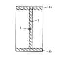
図1は本発明の第1実施形態の平面図、図2は積層フィルムの構成を示す図1におけるI−I断面図、図3は本発明の第2実施形態の平面図、図4は本発明の第3実施形態の平面図であり、2a, 2bは側端熱接着部、3a, 3bは端縁熱接着部、4は底熱接着部、5は合掌熱接着部、6はマイクロウエーブ吸収層、11は熱可塑性フィルム層、12は接着層、13は熱接着性樹脂層をそれぞれ表す。
【0008】
本発明の第1実施形態は、図1、図2に示すとおりであり、熱可塑性フィルム層11と接着層12と熱接着性樹脂層13が積層された積層フィルムからなり、側端熱接着部2a,2b と上下の端縁熱接着部3a,3b により形成された4方シール袋であって、袋を形成する片側の積層フィルムの中央部に円形状のマイクロウエーブ吸収層6が形成された構成である。第1実施形態の袋に内容物を収納した状態で電子レンジで加熱することにより、マイクロウエーブ吸収層6の部分がマイクロウエーブを吸収して加熱されて、マイクロウエーブ吸収層が形成された部分の積層フィルムが溶融して穴が開くので、袋の内部の蒸気を排出させることができる。
【0009】
第1実施形態における積層フィルムの構成は、図2に示すように、熱可塑性フィルム層11とマイクロウエーブ吸収層6と接着層12と熱接着性樹脂層13からなる構成である。絵柄はマイクロウエーブ吸収層6と同様に熱可塑性フィルム層11の内面に形成される。したがって、第1実施形態の電子レンジ加熱用包装容器を製造する際に、熱可塑性フィルム層11の面に絵柄を印刷する印刷工程にてインラインでマイクロウエーブ吸収層6を形成することができるものである。
【0010】
本発明の第2実施形態は、図3に示すとおり、熱可塑性フィルム層11と接着層12と熱接着性樹脂層13が積層された積層フィルムからなり、側端熱接着部2a,2b と上部の端縁熱接着部3aと底熱接着部4により形成された底部に内側へのV字状折込を有する自立性袋であって、袋の上部の端縁熱接着部3aの内端にかかるように4角形状のマイクロウエーブ吸収層6が形成された構成である。第2実施形態の袋を電子レンジで加熱することにより、マイクロウエーブ吸収層6の部分がマイクロウエーブを吸収して加熱されて、端縁熱接着部3aの内端近傍のマイクロウエーブ吸収層6が形成された部分の積層フィルムが溶融して穴が開くか、ないしは端縁熱接着部3aのマイクロウエーブ吸収層6が形成された部分の積層フィルムが収縮ないしは溶融して熱接着部が剥離するので、内部の蒸気を排出させることができる。
【0011】
本発明の第3実施形態は、図4に示すとおり、熱可塑性フィルム層11と接着層12と熱接着性樹脂層13が積層された積層フィルムからなり、合掌熱接着部5と上下の端縁熱接着部3a,3b により形成されたピロータイプ袋であって、合掌熱接着部5の内端にかかるように4角形状のマイクロウエーブ吸収層6が形成された構成である。第3実施形態の袋を電子レンジで加熱することにより、マイクロウエーブ吸収層6の部分が強く加熱されて、合掌熱接着部5以外のマイクロウエーブ吸収層6が形成された部分の積層フィルムが溶けて穴があくか、ないしは合掌熱接着部5のマイクロウエーブ吸収層6が形成された部分の積層フィルムが収縮ないしは溶融して熱接着部が剥離し、内部の蒸気を排出させることができる。
【0012】
第1〜第3実施形態において、袋の形状を4方シール袋、自立性袋、ピロータイプ袋としているが、袋の形状は任意であり3方シール袋、ガセット袋、角底袋の形状とすることができる。また、蓋材を熱接着して密封するトレー状の容器とすることもでき、その場合においても、マイクロウエーブ吸収層は熱接着部の内端にかかるように形成してもよいし、蓋材の中央部に形成してもよい。
【0013】
第1〜第3実施形態において、マイクロウエーブ吸収層6は、図2に示すように、熱可塑性フィルム層11と熱接着性樹脂層12からなる積層フィルムの熱可塑性フィルム層11の内面に形成される。そうすることにより、熱可塑性フィルム層11の内面に絵柄を印刷するグラビア印刷等の印刷工程にてマイクロウエーブ吸収層6を絵柄とインラインで印刷して形成することができるので、マイクロウエーブ吸収層6の形成工程を別に設ける必要がなくなり、製造工程を削減してコストダウンを図ることができる。
【0014】
第1〜第3実施形態においては、積層フィルムに形成するマイクロウエーブ吸収層6の形状を円形状ないしは4角形状とされているが、形状は任意であり3角形状、多角形状、菱形、棒状、模様状等の形状とすることができる。マイクロウエーブ吸収層6はベタ印刷により形成してもよいし、万線状、碁盤目状、格子状等に形成してもよい。
【0015】
マイクロウエーブ吸収層6を形成するためのインキとしては、非金属性樹脂中にマイクロウエーブ吸収粒子を分散させた組成のものが使用できる。非金属性のマイクロウエーブ吸収粒子としては黒鉛、カーボンブラック、酸化亜鉛、酸化錫等が使用できるが、黒鉛、カーボンブラックを使用するのが好ましい。インキのバインダーとなる非金属性樹脂としては通常の熱可塑性フィルム用のインキに使用される樹脂を使用することができる。マイクロウエーブ吸収層6中のマイクロウエーブ吸収粒子の含有率としては5〜20重量%とするのが好ましく、形成するマイクロウエーブ吸収層6の厚さとしては1〜8μmとするのが好ましい。その場合、20〜60μmの深さのグラビア印刷版を使用して1回刷りないしは2回刷りにより形成することができる。上記のマイクロウエーブ吸収層6を形成した電子レンジ加熱用包装容器に内容物を収納した状態で電子レンジで30〜60秒間加熱することにより電子レンジ加熱用包装容器を形成する積層フィルムを溶融させて蒸気の排出する穴を形成することができる。
【0016】
積層フィルムの構成としては、図2に示すように、熱可塑性フィルム層11とマイクロウエーブ吸収層6と接着層12と熱接着性樹脂層13の構成とするのが一般的であるが、熱可塑性フィルム層とマイクロウエーブ吸収層と中間層と熱接着性樹脂層を積層した構成とすることもできる。いずれの場合も、熱可塑性フィルム層の内面にマイクロウエーブ吸収層が形成される。熱可塑性フィルム層11としては2軸延伸ポリエチレンテレフタレート、2軸延伸ナイロン、2軸延伸ポリプロピレン等が使用され、熱接着性樹脂層13としては低密度ポリエチレン、線状低密度ポリエチレン、ポリプロピレン、エチレン−酢酸ビニル共重合体、アイオノマー等が使用され、接着層12としてはウレタン系樹脂、ポリエチレン等の押出樹脂が使用される。中間層としては2軸延伸ポリエチレンテレフタレート、2軸延伸ナイロン、2軸延伸ポリプロピレン等が使用できる。
【0017】
【実施例】
実施例1
厚さ12μmの2軸延伸ポリエチレンテレフタレートの一方の面にグラビア印刷により絵柄層を形成する印刷工程とインラインで絵柄層に見当を合わせた所定位置に深さ50μmのグラビア印刷用ベタ版を使用して10mm径の円形状に下記組成のインキを使用してマイクロウエーブ吸収層を3μmの厚さに形成した後に、絵柄層およびマイクロウエーブ吸収層を形成した面にウレタン樹脂接着剤を使用してドライラミネーションにより厚さ40μmの線状低密度ポリエチレンフィルムを積層した積層フィルムを作製した。
〔マイクロウエーブ吸収層用インキ組成(重量部)〕
カーボンブラック ケッチェンブラックEC(ライオン) 8
ビニル樹脂 ビニライトVAGH(ユニオンカーバイド) 8
溶剤 MEK:トルエン=1:1 84
得られた積層フィルムを使用して、マイクロウエーブ吸収層が中央部にくるように製袋して4方シール袋を作製し、内部に冷凍シューマイを収納した状態で電子レンジにて3分間加熱したところ、加熱を開始して1分後に積層フィルムに穴が形成されて蒸気を排出することができた。
【0018】
【実施例】
実施例2
下記組成のマイクロウエーブ吸収層用インキを使用して、深さ30μmのグラビア印刷用ベタ版にて1辺10mmの4角円形状に印刷して5μmの厚さのマイクロウエーブ吸収層を形成した以外は実施例1と同様にして積層フィルムを作製した。
〔マイクロウエーブ吸収層用インキ組成(重量部)〕
黒鉛 黒鉛CSPE(日本黒鉛工業) 35
アクリル樹脂 アクリディックA801(大日本インキ化学工業) 20
溶剤 MEK:トルエン=1:1 40
硬化剤 コロネートL(日本ホリウレタン工業) 5
得られた積層フィルムを使用して、マイクロウエーブ吸収層が熱接着部の内端にかかるように製袋して自立性袋を作製し、内部に冷凍コロッケを収納した状態で電子レンジにて3分間加熱したところ、加熱を開始して90秒後に積層フィルムに穴が形成されて蒸気を排出することができた。
【0019】
【発明の効果】
熱可塑性フィルム層と熱接着性樹脂層を有する積層フィルムにより形成され、前記熱接着性樹脂層が内側となるように配置され熱接着性樹脂層同士を対向させ熱接着した熱接着部を有する包装容器において、非金属性のマイクロウエーブ吸収粒子を非金属性樹脂中に分散したインキからなるマイクロウエーブ吸収層が、前記熱接着部の対向する前記積層フィルムの一方であって前記熱可塑性フィルムの内面に所定の形状で前記熱接着部の内端にかかるように部分的に形成され、電子レンジ加熱時に発生するマイクロウエーブをマイクロウエーブ吸収層が吸収し加熱されマイクロウエーブ吸収層が形成された積層フィルムが溶融して前記熱接着部の内端に穴が開き蒸気を排出する構成とすることにより、この構成の電子レンジ加熱用包装容器に内容物を収納した状態で電子レンジで加熱することにより、マイクロウエーブ吸収粒子を含むマイクロウエーブ吸収層が加熱されて、積層フィルムを構成する熱可塑性フィルム層と熱接着性樹脂層が溶融し、マイクロウエーブ吸収層が形成された部分に穴を開けることができるので、加熱により発生した容器内部の蒸気を排出することができる。上記の電子レンジ加熱用包装容器において、マイクロウエーブ吸収層の厚さを1〜8μmとした構成とすることにより、電子レンジで加熱することによりマイクロウエーブ吸収層が加熱されて、積層フィルムを構成する熱可塑性フィルム層と熱接着性樹脂層を溶融させることができるとともに、グラビア印刷版にて1回刷りないしは2回刷りすることによりマイクロウエーブ吸収層を形成することが可能となるので製造工程を合理化できる。
【図面の簡単な説明】
【図1】本発明の第1実施形態の平面図。
【図2】積層フィルムの構成を示す図1におけるI−I断面図。
【図3】本発明の第2実施形態の平面図。
【図4】本発明の第3実施形態の平面図。
【符号の説明】
2a, 2b 側端熱接着部
3a, 3b 端縁熱接着部
4 底熱接着部
5 合掌熱接着部
6 マイクロウエーブ吸収層
11 熱可塑性フィルム層
12 接着層
13 熱接着性樹脂層[0001]
BACKGROUND OF THE INVENTION
The present invention relates to a packaging container capable of automatically forming a ventilation portion by heating in a microwave oven.
[0002]
[Prior art]
Conventionally, as a package provided with means for automatically opening a hole when heated in a microwave oven, for example, a package made of a plastic film as described in JP-B-2-49986, non-metallic An adhesion layer composed of non-metallic microwave absorbing particles dispersed in a binder is adhered, and the adhesion layer has a thickness of 10 to 300 μm, and the particles account for at least 10% of the weight of the adhesion layer. Vapor-tight packages are known which are occupying adhesion layers.
However, in the vapor-tight package having the above-described configuration, the thickness of the adhesion layer needs to be increased to 10 to 300 μm. Therefore, when a vapor-tight package made of a plastic film is manufactured, a printing process for printing a pattern is performed. It is difficult to easily form an adhesive layer by printing, and a process such as sticking a tape with a thick adhesive layer to the plastic film that constitutes the package is required, which makes the manufacturing process extremely complicated. There is a drawback that the price of up.
[0003]
[Problems to be solved by the invention]
An object of the present invention is to provide a low-cost microwave oven packaging container that can automatically form a vent when heated in a microwave oven.
[0004]
[Means for Solving the Problems]
A packagehaving a heat-bonded portion formed by a laminated film having a thermoplastic film layer and a heat-adhesive resin layer, arranged so that the heat-adhesive resin layer is on the inside, and heat-bonded with the heat-adhesive resin layers facing each other. acontainer, microwave-absorbing layer made ofnon-metallic microwave absorbing particles from the ink dispersed in nonmetallicresin, the inner surface of one at a in the thermoplastic films of the laminated film opposite the heat-bonding unit predetermined shape formedpartially rests on the inner end of the heat-bondingunit,laminated film microwave absorber layer is heated by absorbing the microwave microwave absorbing layer is generated during the microwave heating isformed bybut be configuredto discharge steam opens a hole in the inner end of the heat-bonded portion is molten, the microwave heating package of this structure By heating in a microwave oven while containing the contents, the microwave absorbing layer containing the microwave absorbing particles is heated, and the thermoplastic film layer and the thermoadhesive resin layer constituting the laminated film are melted. Since the hole can be formed in the portion where the wave absorbing layer is formed, the steam inside the container generated by heating can be discharged.
[0005]
In the microwave oven heating packaging container, by setting the thickness of the microwave absorbing layer to 1 to 8 μm, the microwave absorbing layer is heated by heating in the microwave to constitute a laminated film. Since the thermoplastic film layer and the heat-adhesive resin layer can be melted and a microwave absorbing layer can be formed by printing once or twice with a gravure printing plate, the manufacturing process can be streamlined. It can be set as the packaging container for microwave heating of a low cost.
[0007]
DETAILED DESCRIPTION OF THE INVENTION
Hereinafter, embodiments of the present invention will be described with reference to the drawings.
1 is a plan view of a first embodiment of the present invention, FIG. 2 is a cross-sectional view taken along the line II in FIG. 1 showing the configuration of the laminated film, FIG. 3 is a plan view of the second embodiment of the present invention, and FIG. It is a top view of 3rd Embodiment of invention, 2a, 2b are side edge heat-bonding parts, 3a, 3b are edge heat-bonding parts, 4 is a bottom heat-bonding part, 5 is a palm heat-bonding part, 6 is a microwave Absorption layer, 11 is a thermoplastic film layer, 12 is an adhesive layer, and 13 is a thermoadhesive resin layer.
[0008]
The first embodiment of the present invention is as shown in FIG. 1 and FIG. 2, and is composed of a laminated film in which a
[0009]
As shown in FIG. 2, the laminated film in the first embodiment is composed of a
[0010]
As shown in FIG. 3, the second embodiment of the present invention comprises a laminated film in which a
[0011]
As shown in FIG. 4, the third embodiment of the present invention comprises a laminated film in which a
[0012]
In the first to third embodiments, the shape of the bag is a four-side sealed bag, a self-supporting bag, or a pillow type bag, but the shape of the bag is arbitrary, and the shape of the three-side sealed bag, gusset bag, square bottom bag, can do. Moreover, it can also be set as the tray-shaped container which heat-bonds and seals a cover material, and also in that case, a microwave absorption layer may be formed so that it may cover the inner end of a heat bonding part, and a cover material. You may form in the center part.
[0013]
In the first to third embodiments, the
[0014]
In the first to third embodiments, the shape of the
[0015]
As the ink for forming the
[0016]
As shown in FIG. 2, the laminated film is generally composed of a
[0017]
【Example】
Example 1
Using a solid plate for gravure printing with a depth of 50 μm at a predetermined position aligned with the pattern layer in-line with the printing process of forming a pattern layer by gravure printing on one surface of 12 μm thick biaxially stretched polyethylene terephthalate After forming a microwave absorbing layer to a thickness of 3 μm using a 10 mm diameter circular ink with the following composition, dry lamination using a urethane resin adhesive on the surface on which the pattern layer and the microwave absorbing layer are formed Thus, a laminated film in which a linear low density polyethylene film having a thickness of 40 μm was laminated was produced.
[Ink composition for microwave absorbing layer (parts by weight)]
Carbon Black Ketjen Black EC (Lion) 8
Vinyl resin Vinylite VAGH (Union Carbide) 8
Solvent MEK: Toluene = 1: 1 84
Using the obtained laminated film, a four-side sealed bag was produced by making a bag so that the microwave absorbing layer was in the center, and heated in a microwave oven for 3 minutes with the frozen shhum in inside. However, a hole was formed in the laminated film 1 minute after the start of heating, and the vapor could be discharged.
[0018]
【Example】
Example 2
Except for forming a microwave absorbing layer having a thickness of 5 μm by printing in a square circular shape with a side of 10 mm on a solid plate for gravure printing having a depth of 30 μm using an ink for a microwave absorbing layer having the following composition. Produced a laminated film in the same manner as in Example 1.
[Ink composition for microwave absorbing layer (parts by weight)]
Graphite Graphite CSPE (Nippon Graphite Industries) 35
Acrylic resin Acrydic A801 (Dainippon Ink and Chemicals) 20
Solvent MEK: Toluene = 1: 1 40
Curing agent Coronate L (Nippon Polyurethane Industry) 5
Using the obtained laminated film, a self-supporting bag was produced by making a bag so that the microwave absorbing layer was placed on the inner end of the heat-bonding portion. When heating was performed for a minute, a hole was formed in the laminated film 90 seconds after the start of heating, and the vapor could be discharged.
[0019]
【The invention's effect】
A packagehaving a heat-bonded portion formed by a laminated film having a thermoplastic film layer and a heat-adhesive resin layer, arranged so that the heat-adhesive resin layer is on the inside, and heat-bonded with the heat-adhesive resin layers facing each other. acontainer, microwave-absorbing layer made ofnon-metallic microwave absorbing particles from the ink dispersed in nonmetallicresin, the inner surface of one at a in the thermoplastic films of the laminated film opposite the heat-bonding unit predetermined shape formedpartially rests on the inner end of the heat-bondingunit,laminated film microwave absorber layer is heated by absorbing the microwave microwave absorbing layer is generated during the microwave heating isformed bybut be configuredto discharge steam opens a hole in the inner end of the heat-bonded portion is molten, the microwave heating package of this structure By heating in a microwave oven while containing the contents, the microwave absorbing layer containing the microwave absorbing particles is heated, and the thermoplastic film layer and the thermoadhesive resin layer constituting the laminated film are melted. Since the hole can be formed in the portion where the wave absorbing layer is formed, the steam inside the container generated by heating can be discharged. In the microwave oven heating packaging container, by setting the thickness of the microwave absorbing layer to 1 to 8 μm, the microwave absorbing layer is heated by heating in the microwave to constitute a laminated film. The thermoplastic film layer and the heat-adhesive resin layer can be melted, and the microwave absorbing layer can be formed by printing once or twice with a gravure printing plate, thus streamlining the manufacturing process. I can.
[Brief description of the drawings]
FIG. 1 is a plan view of a first embodiment of the present invention.
FIG. 2 is a cross-sectional view taken along the line II in FIG. 1 showing the configuration of the laminated film.
FIG. 3 is a plan view of a second embodiment of the present invention.
FIG. 4 is a plan view of a third embodiment of the present invention.
[Explanation of symbols]
2a, 2b side edge thermal bonding
3a, 3b Edge
11 Thermoplastic film layer
12 Adhesive layer
13 Thermal adhesive resin layer
Claims (2)
Translated fromJapanesePriority Applications (1)
| Application Number | Priority Date | Filing Date | Title |
|---|---|---|---|
| JP32565599AJP4467683B2 (en) | 1999-11-16 | 1999-11-16 | Packaging container for microwave oven heating |
Applications Claiming Priority (1)
| Application Number | Priority Date | Filing Date | Title |
|---|---|---|---|
| JP32565599AJP4467683B2 (en) | 1999-11-16 | 1999-11-16 | Packaging container for microwave oven heating |
Publications (2)
| Publication Number | Publication Date |
|---|---|
| JP2001139069A JP2001139069A (en) | 2001-05-22 |
| JP4467683B2true JP4467683B2 (en) | 2010-05-26 |
Family
ID=18179253
Family Applications (1)
| Application Number | Title | Priority Date | Filing Date |
|---|---|---|---|
| JP32565599AExpired - Fee RelatedJP4467683B2 (en) | 1999-11-16 | 1999-11-16 | Packaging container for microwave oven heating |
Country Status (1)
| Country | Link |
|---|---|
| JP (1) | JP4467683B2 (en) |
Families Citing this family (13)
| Publication number | Priority date | Publication date | Assignee | Title |
|---|---|---|---|---|
| JP4978077B2 (en)* | 2006-06-22 | 2012-07-18 | 大日本印刷株式会社 | Microwave packaging bag |
| JP4853144B2 (en)* | 2006-07-06 | 2012-01-11 | 大日本印刷株式会社 | Packaging bag |
| JP4968442B2 (en)* | 2006-08-22 | 2012-07-04 | 大日本印刷株式会社 | Sealed container for microwave oven heating |
| CA2621723C (en) | 2007-02-15 | 2014-05-20 | Graphic Packaging International, Inc. | Microwave energy interactive insulating structure |
| JP5155628B2 (en)* | 2007-09-11 | 2013-03-06 | 株式会社カナオカ | Microwave-compatible pouch |
| JP5478823B2 (en)* | 2007-12-27 | 2014-04-23 | 大日本印刷株式会社 | Packaging material |
| EP2265514B1 (en)* | 2008-03-27 | 2016-02-10 | Graphic Packaging International, Inc. | Self-venting microwave heating package |
| JP5482159B2 (en)* | 2009-12-07 | 2014-04-23 | 大日本印刷株式会社 | Microwave oven packaging bag |
| MX2018013418A (en) | 2016-06-03 | 2019-02-28 | Graphic Packaging Int Llc | Microwave packaging material. |
| JP6977426B2 (en)* | 2017-03-29 | 2021-12-08 | 大日本印刷株式会社 | Container with interior bag |
| JP6977438B2 (en)* | 2017-09-20 | 2021-12-08 | 大日本印刷株式会社 | Container with inner bag and container with lid |
| JP2019167120A (en)* | 2018-03-22 | 2019-10-03 | 大日本印刷株式会社 | Pouch |
| JP2021066515A (en)* | 2019-10-28 | 2021-04-30 | 大日本印刷株式会社 | Pouch to be heated in microwave oven and packing material with polygon |
- 1999
- 1999-11-16JPJP32565599Apatent/JP4467683B2/ennot_activeExpired - Fee Related
Also Published As
| Publication number | Publication date |
|---|---|
| JP2001139069A (en) | 2001-05-22 |
Similar Documents
| Publication | Publication Date | Title |
|---|---|---|
| JP4467683B2 (en) | Packaging container for microwave oven heating | |
| JPH0249986B2 (en) | ||
| JP5482159B2 (en) | Microwave oven packaging bag | |
| JP4366772B2 (en) | Packaging for microwave oven | |
| JP2008050013A (en) | Sealed container for microwave oven heating | |
| JP2000025849A (en) | Packaging body for cooking with microwave oven | |
| JPH11292140A (en) | Easy-to-unseal heat-sealable package and manufacture thereof | |
| JP2925652B2 (en) | Food packaging | |
| JPH0618935Y2 (en) | Cover tape for chip-type electronic component packaging | |
| WO2022230588A1 (en) | Composite film, packaging bag, lid member, container with lid, and manufacturing method of composite film | |
| JPH01213180A (en) | Label of sealed vessel for microwave oven | |
| JPH0662175B2 (en) | Partially openable sealed container | |
| JP2004035074A (en) | Inner seal material for container mouth sealing | |
| JPH0417557Y2 (en) | ||
| JPH0414380Y2 (en) | ||
| JP3813233B2 (en) | Easy-open lid material and container using the lid material | |
| JP3245926U (en) | Microwave safe container | |
| JPH038430Y2 (en) | ||
| JP2002127334A (en) | Easy-peelable laminate and method for producing the same | |
| JP2557663B2 (en) | Sealed container | |
| JP2004106858A (en) | Food container lid | |
| JPS6217421Y2 (en) | ||
| JPH079805Y2 (en) | Inner seal material for container mouth sealing | |
| JPS6030210Y2 (en) | container | |
| JPH0215789Y2 (en) |
Legal Events
| Date | Code | Title | Description |
|---|---|---|---|
| A621 | Written request for application examination | Free format text:JAPANESE INTERMEDIATE CODE: A621 Effective date:20060907 | |
| A977 | Report on retrieval | Free format text:JAPANESE INTERMEDIATE CODE: A971007 Effective date:20090612 | |
| A131 | Notification of reasons for refusal | Free format text:JAPANESE INTERMEDIATE CODE: A131 Effective date:20090618 | |
| A521 | Written amendment | Free format text:JAPANESE INTERMEDIATE CODE: A523 Effective date:20090803 | |
| TRDD | Decision of grant or rejection written | ||
| A01 | Written decision to grant a patent or to grant a registration (utility model) | Free format text:JAPANESE INTERMEDIATE CODE: A01 Effective date:20100216 | |
| A01 | Written decision to grant a patent or to grant a registration (utility model) | Free format text:JAPANESE INTERMEDIATE CODE: A01 | |
| A61 | First payment of annual fees (during grant procedure) | Free format text:JAPANESE INTERMEDIATE CODE: A61 Effective date:20100224 | |
| R150 | Certificate of patent (=grant) or registration of utility model | Free format text:JAPANESE INTERMEDIATE CODE: R150 | |
| FPAY | Renewal fee payment (prs date is renewal date of database) | Free format text:PAYMENT UNTIL: 20130305 Year of fee payment:3 | |
| FPAY | Renewal fee payment (prs date is renewal date of database) | Free format text:PAYMENT UNTIL: 20130305 Year of fee payment:3 | |
| FPAY | Renewal fee payment (prs date is renewal date of database) | Free format text:PAYMENT UNTIL: 20140305 Year of fee payment:4 | |
| LAPS | Cancellation because of no payment of annual fees |