JP4467278B2 - Escalator and tip skirt structure - Google Patents
Escalator and tip skirt structureDownload PDFInfo
- Publication number
- JP4467278B2 JP4467278B2JP2003352302AJP2003352302AJP4467278B2JP 4467278 B2JP4467278 B2JP 4467278B2JP 2003352302 AJP2003352302 AJP 2003352302AJP 2003352302 AJP2003352302 AJP 2003352302AJP 4467278 B2JP4467278 B2JP 4467278B2
- Authority
- JP
- Japan
- Prior art keywords
- skirt portion
- tip
- escalator
- balustrade
- belt
- Prior art date
- Legal status (The legal status is an assumption and is not a legal conclusion. Google has not performed a legal analysis and makes no representation as to the accuracy of the status listed.)
- Expired - Lifetime
Links
- 238000012423maintenanceMethods0.000description4
- 230000000694effectsEffects0.000description3
- 239000012141concentrateSubstances0.000description2
- 238000001514detection methodMethods0.000description2
- 238000007689inspectionMethods0.000description2
- 239000005357flat glassSubstances0.000description1
- 238000009434installationMethods0.000description1
- 230000000630rising effectEffects0.000description1
- 229910001220stainless steelInorganic materials0.000description1
- 239000010935stainless steelSubstances0.000description1
Images


Classifications
- B—PERFORMING OPERATIONS; TRANSPORTING
- B66—HOISTING; LIFTING; HAULING
- B66B—ELEVATORS; ESCALATORS OR MOVING WALKWAYS
- B66B29/00—Safety devices of escalators or moving walkways
- B66B29/02—Safety devices of escalators or moving walkways responsive to, or preventing, jamming by foreign objects
- B66B29/04—Safety devices of escalators or moving walkways responsive to, or preventing, jamming by foreign objects for balustrades or handrails
- B—PERFORMING OPERATIONS; TRANSPORTING
- B66—HOISTING; LIFTING; HAULING
- B66B—ELEVATORS; ESCALATORS OR MOVING WALKWAYS
- B66B27/00—Indicating operating conditions of escalators or moving walkways
Landscapes
- Escalators And Moving Walkways (AREA)
Description
Translated fromJapanese本発明は、エスカレータに係り、特に、エスカレータの欄干先端部の先端スカート部に表示装置等を集中配置するようにしたエスカレータおよび先端スカート部構造に関する。 The present invention relates to an escalator, and more particularly, to an escalator and a tip skirt portion structure in which a display device and the like are centrally arranged on a tip skirt portion of a balustrade tip portion of an escalator.
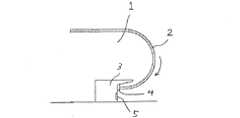
図5は、エスカレータの欄干先端部を示す。この図5において、参照番号1は欄干先端部を示し、2は、手摺りベルトであり、矢印方向に移動している。欄干先端部1の下部が先端スカート部3になっている。 FIG. 5 shows the balustrade tip of the escalator. In FIG. 5,
従来のエスカレータでは、先端スカート部3の正面には、手摺りベルト進入口4が設けられている。また、先端スカート部3の正面には、踏段の走行方向などの運転状況を表示する表示装置5が設けられているのが一般的である。 In the conventional escalator, a handrail belt entrance 4 is provided in front of the front
しかしながら、従来のエスカレータでは、欄干先端部1の方が先端スカート部3よりも昇降口側に突き出ている構造になっている。このため、昇降口から乗り込もうとする乗客にとっては、視点の高さによっては先端スカート部3に設けられている表示装置5が欄干先端部1に遮られて見難くなっており、特に、片側の欄干先端部1だけに表示装置5が設置されている場合に、乗客の乗り込む位置によっては表示装置5がまったく視界から遮られるという問題があった。 However, the conventional escalator has a structure in which the balustrade
また、従来のエスカレータの先端スカート部3では、手摺りベルト進入口4に進入していく手摺りベルト2と床面の間のスペースが狭くなっており、乗客の荷物等がこのスペースに嵌り込む危険性があった。 Further, in the
さらに、乗客が乗り込む際に買物カートを引き込もうとして、先端スカート部の正面に買物カートをぶつけしまった場合、当たり具合によっては買物カートが踏段の方ではなくフロア側に跳ね返されてしまい、そのため乗客が転倒したり、買物カートだけ上階のフロアに残留したりというような問題があった。 In addition, when a passenger tries to pull in a shopping cart when getting in, if the shopping cart hits the front of the tip skirt part, the shopping cart will be bounced back to the floor side instead of the step depending on how it hits, so the passenger However, there were problems such as falling down and only the shopping cart remaining on the upper floor.
そこで、本発明の目的は、前記従来技術の有する問題点を解消し、表示装置などの視認性を高めるとともに、乗客輸送を安全なものとするように改良した先端スカート部を備えたエスカレータを提供することにある。 SUMMARY OF THE INVENTION Accordingly, an object of the present invention is to provide an escalator having an improved tip skirt that eliminates the problems of the prior art, improves the visibility of display devices, etc., and makes passenger transportation safe. There is to do.
前記の目的を達成するために、請求項1に係る発明は、踏段の両側に沿ってそれぞれ欄干を配置し、前記欄干の外周部に巻き付けた手摺りベルトを折り返す欄干先端部と前記手摺りベルトのベルト進入口を有する先端スカート部を設けてなるエスカレータにおいて、前記ベルト進入口が設けられる前記先端スカート部の正面は、水平面および乗降口からの乗り込み方向に対してそれぞれ所定の角度をなす2つの傾斜面を含み、前記傾斜面は共に水平面に対して5〜30°の角度をなし、一方の傾斜面はさらに乗り込み方向に平行な垂直面対して45°〜85°の角度をなし、前記一方の傾斜面に表示面を合わせるようにして表示装置を配置したことを特徴としている。In order to achieve the above-mentioned object, the invention according to
請求項3に係る発明は、請求項2に記載の発明において、前記ベルト進入口よりも前記先端スカート部正面の下端縁がさらに前方に延出していることを特徴としている。 The invention according to
請求項4に係る発明は、請求項3に記載の発明において、前記先端スカート部のベルト進入口は、前記先端スカート部正面から突出して傾斜していることを特徴としている。 The invention according to claim 4 is characterized in that, in the invention according to
請求項5に係る発明は、請求項4に記載の発明において、前記先端スカート部のベルト進入口の開口する端面は、水平面に対して60〜85°の傾斜を有することを特徴としている。 The invention according to
請求項6に係る発明は、請求項5に記載の発明において、前記先端スカート部のベルト進入口における手摺りベルトの移動方向が水平面に対して5〜30°の角度をなすことを特徴としている。 The invention according to claim 6 is characterized in that, in the invention according to
請求項7に係る発明は、請求項3乃至6に記載された発明において、前記先端スカート部のベルト進入口の床面からの高さは、少なくとも170mm以上あることを特徴としている。 The invention according to claim 7 is the invention described in
請求項8に係る発明は、請求項1に記載された発明において、前記先端スカート部の正面は、角が丸みを帯びた滑らかに湾曲する曲面からなることを特徴としている。 The invention according to claim 8 is characterized in that, in the invention described in
請求項9に係る発明は、請求項1に記載された発明において、前記先端スカート部は、スイッチ類、センサ、表示装置等の各種機器の配置集中機能を有することを特徴としている。 The invention according to claim 9 is characterized in that, in the invention described in
請求項10に係る発明は、請求項1乃至9のいずれかの項に記載の前記先端スカート部は、一体として前記欄干先端部に取り付け、交換可能にユニット化された構造体からなることを特徴としている。 The invention according to
以上の説明から明らかなように、本発明によれば、エスカレータに乗り込もうとする乗客にとって、乗降口に近づいても表示装置が欄干先端部の陰になって見難くなるというようなことがなく、視認性を大幅に向上させることができる。 As is clear from the above description, according to the present invention, for passengers trying to get into the escalator, even if approaching the entrance / exit, the display device does not become difficult to see behind the balustrade tip, Visibility can be greatly improved.
また、本発明によれば、床面と欄干先端部との間に挟まれてできる空間を大きくとり、また、床面とベルト進入口との間で荷物等が挟まる危険が防止できる構造とすることができる。 In addition, according to the present invention, a space formed between the floor surface and the balustrade tip can be increased, and a structure that can prevent the danger of a load being caught between the floor surface and the belt entrance is provided. be able to.
さらに、本発明によれば、先端スカート部を買物カートなどがに当たって進行方向に誘導される形状に構成することができるので、フロア側に買物カートが跳ね返されることによる転倒事故や乗降口での渋滞を防止できる。 Furthermore, according to the present invention, the tip skirt portion can be configured to be guided in the direction of travel when hitting a shopping cart or the like, so that a fall accident caused by the shopping cart bouncing back to the floor side or traffic jam at the entrance Can be prevented.
また、本発明によれば、運転操作機能や安全機能を集中させ、保守係員による保守点検作業効率の向上を図ることができる。 Further, according to the present invention, it is possible to concentrate driving operation functions and safety functions, and to improve maintenance inspection work efficiency by maintenance staff.
以下、本発明によるエスカレータの一実施形態について、添付の図面を参照しながら説明する。
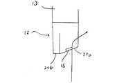
図1は、本実施形態によるエスカレータの乗降口周辺を示す。この図1において、参照番号10は、欄干先端部を示している。エスカレータの欄干には、板ガラスからなるもの、ステンレス板からなるもの等がある。本発明はいずれにも適用することができる。この図1では、昇降口に向かって左側の欄干の欄干先端部10を図示し、右側の欄干先端部については省略している。手摺りベルト11は、欄干先端部10で折り返されて方向を反転して移動するようになっている。参照番号12は、先端スカート部の全体を示している。この先端スカート部12は、デッキカバー13の両端部に取り付けられている。なお、14は踏段を示している。踏段14の表面の周囲には黄色のデマケーション14aラインが付けられている。Hereinafter, an embodiment of an escalator according to the present invention will be described with reference to the accompanying drawings.
FIG. 1 shows the vicinity of an entrance / exit of an escalator according to this embodiment. In FIG. 1,
先端スカート部12の正面には、ベルト進入口15が設けられており、その下側には、エスカレータの進行方向などの運転状態などを表示する表示装置16が取り付けられている。なお、表示装置16は、乗降口の両側の先端スカート部12のうち、両方に設けてもよいし片方のみでもよい。 A
また、先端スカート部14の内側の側面には、エスカレータの操作スイッチ17、インレットスイッチ18、利用者検出センサ19などの各種スイッチや補助機器類を配置し、運転操作機能や安全機能を集中させている。また、このような補助機器類としては、例えば、振動発生装置を配置してもよい。この振動発生装置は、乗客の足がデッキカバー13の内側側面に押し付けられて時に、その押付力を検出し、それが第1基準値を越えたら振動を発生して内側側面を介して乗客に伝えるように構成された装置である。乗客が振動に気づかずにさらに強く押し付け第2基準値を超えた場合にはエスカレータの運転が停止される。 In addition, various switches and auxiliary equipment such as an
このような先端スカート部12においては、その正面は傾斜面20a、20bになっている。正面の傾斜面20a、20bは、水平面に対して5°〜30°の範囲で傾斜している。そして、傾斜面20aの方はそれに加えて乗り込み方向に対して45°〜85°の範囲で傾斜していることが好ましい。表示装置16はその表示面を傾斜面20aの傾斜に合わせるようにして取り付けられている。 The front surface of the
先端スカート部12の正面では、この実施形態のように、傾斜面20a、20bは角が丸みを帯びた滑らかに湾曲する曲面から構成されていることが好ましいが、平坦な曲面であってよい。 In the front surface of the
次に、図2は、欄干先端部の側面を示す。先端スカート部12の正面の下端縁12aは、ベルト進入口15よりもさらに距離Aだけ前方に延出している。先端スカート部12のベルト進入口15は、先端スカート部12の正面から突出するようになっており、進入口の開口する端面15aは、水平面に対して傾斜している。この傾斜角度は、好ましくは60〜85°の範囲である。そして、これに伴い、先端スカート部12のベルト進入口15を出入りする手摺りベルト11の移動する方向についても水平面に対して所定の角度をもっており、端面15aの傾斜角度に合わせてベルト11の速度ベクトルの方向が水平面に対して5〜30°の範囲の角度Cをなすようになっていることが好ましい。そして、先端スカート部12のベルト進入口15の床面からの高さHは、少なくとも170mm以上が確保されている。 Next, FIG. 2 shows the side of the balustrade tip. A lower end edge 12 a in front of the
本実施形態は、以上のように構成されるものであり、次に、その作用に並びに効果について説明する。
本実施形態によれば、エスカレータ乗降口の両側に配置される先端スカート部12では、水平面および乗り込み方向に対して傾斜している傾斜面20aを正面に設け、傾斜面20aの傾斜に合わせるよう表示装置16を配置している。ここで、図1では、表示装置16にエスカレータの進行方向が上昇であることを示している。この図1に示されるように、乗降口からエスカレータに乗り込もうとする乗客にとって、乗降口に近づいても表示装置16は欄干先端部10の陰になって見難くなるというようなことがなく、視認性を大幅に向上させることができる。また、たとえ表示装置16が片方の先端スカート部12にのみ設けられていない場合でも、乗客の位置や視線の高さによらば視認性が低下することがない。The present embodiment is configured as described above. Next, the operation and effects will be described.
According to the present embodiment, the front
また、本実施形態によれば、先端スカート部12の正面を傾斜面とすることは表示装置15の視認性の向上に加えて、次のような利点もある。すなわち、先端スカート部12の下端縁12aを、ベルト進入口15よりもさらに距離Aだけ前方に延出させることにより、床面と欄干先端部10との間に挟まれてできる空間を大きくとることができるようになる。この場合、さらにベルト進入口14は正面の傾斜面20aから突き出る構造とし、ベルト進入口14の端面14aを水平面に対して60〜85°の範囲で傾斜させるとともに、ベルト進入口14における手摺りベルト11の移動方向に水平面に対して5〜30の角度をなすようにしていることで、床面とベルト進入口14とのクリアランスを大きくとることができる。したがって、床面と欄干先端部10の間に乗客に荷物等か挟まりにくい構造とすることができる。 Further, according to the present embodiment, making the front surface of the
なお、ベルト進入口14の高さHを少なくとも170mm以上とることで、子供が乗降口で転びその子供の頭部が床面と手摺りベルト11の間に挟まれ髪が巻き込まれるような事故を防止可能な構造とすることができる。 By making the height H of the
さらに、本実施形態によれば、先端スカート部12の正面を傾斜面20a、20bとした上で、この実施形態のように、傾斜面20a、20bは角が丸みを帯びた滑らかに湾曲する曲面から構成されている。このようにすることにより、図3、図4に示すように、乗客が乗降口から乗り込むときに買物カートなどを先端スカート部12の正面にぶつけたとしても、矢印で示すように、傾斜面20aに当たって進行方向に誘導される形状になってので、フロア側に買物カートが跳ね返されることによる転倒事故や乗降口での渋滞を防止できる。 Furthermore, according to the present embodiment, the front surface of the
また、本実施形態によれば、先端スカート部12の内側の側面には、エスカレータの操作スイッチ17、インレットスイッチ18、利用者検出センサ19などの各種スイッチや補助機器類を配置し、運転操作機能や安全機能を集中させている。これにより、保守係員にとって保守点検作業効率の向上を図っている。 In addition, according to the present embodiment, various switches and auxiliary devices such as the
このような、先端スカート部12は、欄干先端部10において、取り付け、交換可能にユニット化した構造体として構成することもできる。そうすれば、据え付け作業の効率化も達成することが可能となる。 Such a
以上、本発明について好適な実施形態を挙げて説明したが、本発明は、踏段が水平に移動するマンコンベア形の欄干先端部にも適用することができる。 While the present invention has been described with reference to a preferred embodiment, the present invention can also be applied to a man conveyor type balustrade tip where the steps move horizontally.
10 欄干先端部
11 手摺りベルト
12 先端スカート部
13 デッキカバー
14 踏段
15 ベルト進入口
16 表示装置
17 操作スイッチ
20a、20b 傾斜面DESCRIPTION OF
Claims (9)
Translated fromJapanese前記ベルト進入口が設けられる前記先端スカート部の正面は、水平面および乗降口からの乗り込み方向に対してそれぞれ所定の角度をなす2つの傾斜面を含み、前記傾斜面は共に水平面に対して5〜30°の角度をなし、一方の傾斜面はさらに乗り込み方向に平行な垂直面に対して45°〜85°の角度をなし、前記一方の傾斜面に表示面を合わせるようにして表示装置を配置したことを特徴とするエスカレータ。In an escalator comprising a balustrade along each side of the step, and provided with a balustrade tip portion that folds a balustrade belt wound around an outer periphery of the balustrade and a tip skirt portion having a belt entrance of the balustrade belt,
The front surface of the tip skirt portion where the belt entrance is provided includestwo inclined surfaces each having a predetermined angle with respect to the horizontal plane and the boarding direction from the entrance, andboth of the inclined surfaces are 5 to 5 relative to the horizontal plane. An angle of 30 ° is formed, and one inclined surface further forms an angle of 45 ° to 85 ° with respect to a vertical surface parallel to the boarding direction , and the display device is arranged so that the display surface is aligned with theone inclined surface. An escalator characterized by
Priority Applications (9)
| Application Number | Priority Date | Filing Date | Title |
|---|---|---|---|
| JP2003352302AJP4467278B2 (en) | 2003-10-10 | 2003-10-10 | Escalator and tip skirt structure |
| TW093130398ATWI297322B (en) | 2003-10-10 | 2004-10-07 | Escalator and skirt end structure |
| CN2004800294620ACN1863727B (en) | 2003-10-10 | 2004-10-08 | Escalator and skirt end structure |
| EP04773755AEP1673303B1 (en) | 2003-10-10 | 2004-10-08 | Escalator and skirt end structure |
| PCT/JP2004/015304WO2005035426A1 (en) | 2003-10-10 | 2004-10-08 | Escalator and skirt end structure |
| DE602004026611TDE602004026611D1 (en) | 2003-10-10 | 2004-10-08 | ROLLER STAIRCASE AND MOUNTING END STRUCTURE |
| US10/575,103US7404476B2 (en) | 2003-10-10 | 2004-10-08 | Escalator and skirt end structure |
| KR1020067008928AKR100825155B1 (en) | 2003-10-10 | 2004-10-08 | Escalator and Skirt Tip Structure |
| MYPI20044148AMY139046A (en) | 2003-10-10 | 2004-10-09 | Escalator and skirt end structure |
Applications Claiming Priority (1)
| Application Number | Priority Date | Filing Date | Title |
|---|---|---|---|
| JP2003352302AJP4467278B2 (en) | 2003-10-10 | 2003-10-10 | Escalator and tip skirt structure |
Publications (2)
| Publication Number | Publication Date |
|---|---|
| JP2005112613A JP2005112613A (en) | 2005-04-28 |
| JP4467278B2true JP4467278B2 (en) | 2010-05-26 |
Family
ID=34543282
Family Applications (1)
| Application Number | Title | Priority Date | Filing Date |
|---|---|---|---|
| JP2003352302AExpired - LifetimeJP4467278B2 (en) | 2003-10-10 | 2003-10-10 | Escalator and tip skirt structure |
Country Status (9)
| Country | Link |
|---|---|
| US (1) | US7404476B2 (en) |
| EP (1) | EP1673303B1 (en) |
| JP (1) | JP4467278B2 (en) |
| KR (1) | KR100825155B1 (en) |
| CN (1) | CN1863727B (en) |
| DE (1) | DE602004026611D1 (en) |
| MY (1) | MY139046A (en) |
| TW (1) | TWI297322B (en) |
| WO (1) | WO2005035426A1 (en) |
Families Citing this family (16)
| Publication number | Priority date | Publication date | Assignee | Title |
|---|---|---|---|---|
| JP4475911B2 (en)* | 2003-10-10 | 2010-06-09 | 東芝エレベータ株式会社 | Man conveyor display device |
| US7729789B2 (en) | 2004-05-04 | 2010-06-01 | Fisher-Rosemount Systems, Inc. | Process plant monitoring based on multivariate statistical analysis and on-line process simulation |
| JP2007536634A (en) | 2004-05-04 | 2007-12-13 | フィッシャー−ローズマウント・システムズ・インコーポレーテッド | Service-oriented architecture for process control systems |
| JP2007223720A (en)* | 2006-02-23 | 2007-09-06 | Nippon Otis Elevator Co | Display device for escalator |
| FR2942786B1 (en)* | 2009-03-03 | 2016-04-15 | Ficap | PROTECTIVE DEVICE FOR TRANSFER TREADMILL |
| US8881039B2 (en) | 2009-03-13 | 2014-11-04 | Fisher-Rosemount Systems, Inc. | Scaling composite shapes for a graphical human-machine interface |
| JP5115502B2 (en)* | 2009-03-16 | 2013-01-09 | 三菱電機ビルテクノサービス株式会社 | Escalator operation direction display device |
| US8825183B2 (en) | 2010-03-22 | 2014-09-02 | Fisher-Rosemount Systems, Inc. | Methods for a data driven interface based on relationships between process control tags |
| EP2748097A4 (en)* | 2011-09-15 | 2015-04-08 | Kone Corp | ROLLING SIDEWALK |
| CN102442599A (en)* | 2011-12-30 | 2012-05-09 | 上海爱登堡电梯股份有限公司 | Escalator and handrail strap entry guard |
| MX373880B (en)* | 2013-12-20 | 2020-03-26 | Inventio Ag | Arrangement of a monitoring sensor in an escalator or in a moving walkway |
| US9896309B2 (en)* | 2014-05-06 | 2018-02-20 | Otis Elevator Company | Object detector, and method for controlling a passenger conveyor system using the same |
| CN104973492A (en)* | 2015-07-06 | 2015-10-14 | 苏州新达电扶梯部件有限公司 | Sensing escalator inlet and outlet device |
| CN107662873B (en) | 2016-07-29 | 2021-08-24 | 奥的斯电梯公司 | Sensor assembly, safety system and passenger conveyor |
| JP6874063B2 (en)* | 2019-07-03 | 2021-05-19 | 東芝エレベータ株式会社 | Passenger conveyor |
| CN115210168A (en)* | 2020-02-28 | 2022-10-18 | 因温特奥股份公司 | People conveyor and method for operating a people conveyor |
Family Cites Families (12)
| Publication number | Priority date | Publication date | Assignee | Title |
|---|---|---|---|---|
| JPS63123575A (en) | 1986-11-11 | 1988-05-27 | Honda Motor Co Ltd | seam welding machine |
| JPS63123575U (en)* | 1987-02-02 | 1988-08-11 | ||
| US5431271A (en)* | 1994-04-08 | 1995-07-11 | Otis Elevator Company | Indicator for a passenger conveying device |
| JPH07285774A (en) | 1994-04-19 | 1995-10-31 | Hitachi Building Syst Eng & Service Co Ltd | Escalator failure indicator |
| MY118807A (en)* | 1996-12-16 | 2005-01-31 | Inventio Ag | Device for monitoring the entry area of an escalator or moving walkway |
| US5782330A (en)* | 1996-12-20 | 1998-07-21 | Otis Elevator Company | Information display and control device for a passenger conveyor |
| DE19826773A1 (en) | 1998-06-11 | 1999-12-16 | Detlev Abraham | Method for indicating the direction of movement of an escalator or traveling path |
| EP1097898B1 (en)* | 1999-05-17 | 2005-10-05 | Mitsubishi Denki Kabushiki Kaisha | Controller of passenger conveyor and passenger sensor |
| EP1620334B1 (en) | 2003-04-04 | 2017-06-07 | Otis Elevator Company | Traffic flow indicator for a passenger conveyor |
| US7134539B2 (en)* | 2003-08-20 | 2006-11-14 | Chul Soon Im | Guard device for escalator handrail |
| ES2366436T3 (en)* | 2003-11-04 | 2011-10-20 | Otis Elevator Company | AUTOMATIC OPERATION OF A LOW SPEED PASSENGER CONVEYOR. |
| ZA200409385B (en)* | 2003-12-08 | 2005-09-28 | Inventio Ag | Equipment for monitoring the space in front of escalators and moving walkways by high-frequency sensors |
- 2003
- 2003-10-10JPJP2003352302Apatent/JP4467278B2/ennot_activeExpired - Lifetime
- 2004
- 2004-10-07TWTW093130398Apatent/TWI297322B/ennot_activeIP Right Cessation
- 2004-10-08CNCN2004800294620Apatent/CN1863727B/ennot_activeExpired - Fee Related
- 2004-10-08WOPCT/JP2004/015304patent/WO2005035426A1/enactiveApplication Filing
- 2004-10-08USUS10/575,103patent/US7404476B2/ennot_activeExpired - Fee Related
- 2004-10-08EPEP04773755Apatent/EP1673303B1/ennot_activeExpired - Lifetime
- 2004-10-08KRKR1020067008928Apatent/KR100825155B1/ennot_activeExpired - Fee Related
- 2004-10-08DEDE602004026611Tpatent/DE602004026611D1/ennot_activeExpired - Lifetime
- 2004-10-09MYMYPI20044148Apatent/MY139046A/enunknown
Also Published As
| Publication number | Publication date |
|---|---|
| WO2005035426A1 (en) | 2005-04-21 |
| CN1863727B (en) | 2010-09-01 |
| MY139046A (en) | 2009-08-28 |
| CN1863727A (en) | 2006-11-15 |
| TWI297322B (en) | 2008-06-01 |
| DE602004026611D1 (en) | 2010-05-27 |
| US7404476B2 (en) | 2008-07-29 |
| EP1673303B1 (en) | 2010-04-14 |
| KR20060085945A (en) | 2006-07-28 |
| KR100825155B1 (en) | 2008-04-24 |
| US20070084696A1 (en) | 2007-04-19 |
| JP2005112613A (en) | 2005-04-28 |
| EP1673303A1 (en) | 2006-06-28 |
| TW200526505A (en) | 2005-08-16 |
Similar Documents
| Publication | Publication Date | Title |
|---|---|---|
| JP4467278B2 (en) | Escalator and tip skirt structure | |
| JP4619030B2 (en) | Passenger conveyor | |
| KR101724600B1 (en) | Screen door apparatus and method for controlling the same | |
| JP2012106848A (en) | Passenger conveyor | |
| JP5231916B2 (en) | Inclined passenger conveyor safety device | |
| JP2006176282A (en) | Man-conveyor | |
| JP2009190893A (en) | Passenger transport body protection | |
| JP4835211B2 (en) | Passenger conveyor | |
| JPH0430220Y2 (en) | ||
| JPH09301665A (en) | Passenger conveyor safety devices | |
| JP2006062861A (en) | Passenger conveyor with guidance | |
| JP4994118B2 (en) | Passenger conveyor | |
| JPH0412987A (en) | Passenger conveyor | |
| JP2009190895A (en) | Passenger transport protection equipment | |
| JP2555108B2 (en) | Passenger conveyor safety equipment | |
| JP5010984B2 (en) | Passenger conveyor | |
| JPH06227783A (en) | Passenger conveyor safety equipment | |
| JPH07468Y2 (en) | Passenger conveyor safety equipment | |
| JP5487408B2 (en) | Passenger conveyor inlet safety device | |
| JPH02204295A (en) | Safety device for escalator | |
| JP2005212920A (en) | Man conveyor entrance / exit device | |
| JPH09249372A (en) | Passenger conveyor protection equipment | |
| JPH1036053A (en) | Passenger conveyor safety equipment | |
| JP2004217408A (en) | Railing on passenger conveyor | |
| JPH0578083A (en) | Safety equipment for passenger conveyors |
Legal Events
| Date | Code | Title | Description |
|---|---|---|---|
| A621 | Written request for application examination | Free format text:JAPANESE INTERMEDIATE CODE: A621 Effective date:20061010 | |
| A131 | Notification of reasons for refusal | Free format text:JAPANESE INTERMEDIATE CODE: A131 Effective date:20090728 | |
| A521 | Written amendment | Free format text:JAPANESE INTERMEDIATE CODE: A523 Effective date:20090928 | |
| TRDD | Decision of grant or rejection written | ||
| A01 | Written decision to grant a patent or to grant a registration (utility model) | Free format text:JAPANESE INTERMEDIATE CODE: A01 Effective date:20100129 | |
| A01 | Written decision to grant a patent or to grant a registration (utility model) | Free format text:JAPANESE INTERMEDIATE CODE: A01 | |
| A61 | First payment of annual fees (during grant procedure) | Free format text:JAPANESE INTERMEDIATE CODE: A61 Effective date:20100223 | |
| R150 | Certificate of patent or registration of utility model | Free format text:JAPANESE INTERMEDIATE CODE: R150 | |
| FPAY | Renewal fee payment (event date is renewal date of database) | Free format text:PAYMENT UNTIL: 20130305 Year of fee payment:3 |