JP4466715B2 - Legged robot and control method thereof - Google Patents
Legged robot and control method thereofDownload PDFInfo
- Publication number
- JP4466715B2 JP4466715B2JP2007278107AJP2007278107AJP4466715B2JP 4466715 B2JP4466715 B2JP 4466715B2JP 2007278107 AJP2007278107 AJP 2007278107AJP 2007278107 AJP2007278107 AJP 2007278107AJP 4466715 B2JP4466715 B2JP 4466715B2
- Authority
- JP
- Japan
- Prior art keywords
- distance
- leg
- foot
- distance sensors
- road surface
- Prior art date
- Legal status (The legal status is an assumption and is not a legal conclusion. Google has not performed a legal analysis and makes no representation as to the accuracy of the status listed.)
- Expired - Fee Related
Links
Images


Classifications
- B—PERFORMING OPERATIONS; TRANSPORTING
- B25—HAND TOOLS; PORTABLE POWER-DRIVEN TOOLS; MANIPULATORS
- B25J—MANIPULATORS; CHAMBERS PROVIDED WITH MANIPULATION DEVICES
- B25J5/00—Manipulators mounted on wheels or on carriages
- B—PERFORMING OPERATIONS; TRANSPORTING
- B62—LAND VEHICLES FOR TRAVELLING OTHERWISE THAN ON RAILS
- B62D—MOTOR VEHICLES; TRAILERS
- B62D57/00—Vehicles characterised by having other propulsion or other ground- engaging means than wheels or endless track, alone or in addition to wheels or endless track
- B62D57/02—Vehicles characterised by having other propulsion or other ground- engaging means than wheels or endless track, alone or in addition to wheels or endless track with ground-engaging propulsion means, e.g. walking members
- B62D57/032—Vehicles characterised by having other propulsion or other ground- engaging means than wheels or endless track, alone or in addition to wheels or endless track with ground-engaging propulsion means, e.g. walking members with alternately or sequentially lifted supporting base and legs; with alternately or sequentially lifted feet or skid
- B—PERFORMING OPERATIONS; TRANSPORTING
- B25—HAND TOOLS; PORTABLE POWER-DRIVEN TOOLS; MANIPULATORS
- B25J—MANIPULATORS; CHAMBERS PROVIDED WITH MANIPULATION DEVICES
- B25J13/00—Controls for manipulators
- B25J13/08—Controls for manipulators by means of sensing devices, e.g. viewing or touching devices
Landscapes
- Engineering & Computer Science (AREA)
- Mechanical Engineering (AREA)
- Chemical & Material Sciences (AREA)
- Combustion & Propulsion (AREA)
- Transportation (AREA)
- Robotics (AREA)
- Human Computer Interaction (AREA)
- Manipulator (AREA)
Abstract
Description
Translated fromJapanese本発明は脚式ロボット、及びその制御方法に関する。 The present invention relates to a legged robot and a control method thereof.
脚式移動ロボットを転倒させずに安定して移動させるためには、ロボットの支持脚を路面に密着させることが必要である。また、ロボットの遊脚を着地させる際には、予期しない路面凹凸からの外乱力を抑制することも効果的である。このため、ロボットの足裏と路面との関係を目標どおりに制御することが重要である。 In order to move the legged mobile robot stably without falling down, it is necessary that the supporting leg of the robot is in close contact with the road surface. Further, when landing the free leg of the robot, it is also effective to suppress the disturbance force from unexpected road surface unevenness. For this reason, it is important to control the relationship between the soles of the robot and the road surface as desired.
従来、ロボットの足裏にセンサを配置して、センサの出力値を目標値に追従させる多くの技術が知られている。特許文献1には、複雑な凹凸がある不安定な路面状況においても、足裏における床反力を正確に検出して歩行安定性を実現するための、二脚歩行式移動装置及びその歩行制御装置が開示されている。特許文献1記載の二脚歩行式移動装置では、足裏に配置された少なくとも3個の3軸力センサのうち、検出している力の大きい順に3個選択し、その床反力データに基づいて歩容を修正する。 Conventionally, many techniques are known in which a sensor is arranged on the sole of a robot and the output value of the sensor follows a target value. Patent Document 1 discloses a biped walking type moving device and its walking control for accurately detecting a floor reaction force on a sole and realizing walking stability even in an unstable road surface condition having complicated unevenness. An apparatus is disclosed. In the biped walking type moving apparatus described in Patent Document 1, three at least three triaxial force sensors arranged on the sole are selected in descending order of the detected force, and based on the floor reaction force data. Correct the gait.
特許文献2には、複雑な凹凸がある不安定な路面状況においても足部が確実に着地できるようにするための、二脚歩行式移動装置が開示されている。特許文献2記載の二脚歩行式移動装置では、踵部と足先部に三軸力センサを備え、それら力センサの信号に基づいて踵部と足先部で3点支持するように歩容データを修正する。 Patent Document 2 discloses a bipedal walking type moving device for ensuring that a foot can land even in an unstable road surface condition having complicated unevenness. In the biped walking type movement apparatus described in Patent Document 2, a triaxial force sensor is provided on the buttocks and the toes, and the gait is supported at the buttocks and the toes based on the signals of these force sensors. Correct the data.
特許文献3には、脚式移動ロボットの歩行中における路面の表面状態や路面への足部の接地状態を正確に判断するための、脚式移動ロボットのための足部構造、並びに路面検知装置が開示されている。特許文献3記載の脚式移動ロボットのための足部構造では、足部ベース体と、足部ベース体の底面に配置されて、足部と路面との接近及び接地状況を測定する路面検知部と、を備える。路面検知子は足部ベース体に対して出没自在に取り付けられ、路面検知部が路面検知子の出没位置を検出する。また、実施例では、足裏距離センサを使用して、足裏と路面との距離をフィードバック制御することにより安定化を図る手段が開示されている。
しかしながら、特許文献1及び2記載の技術では、ちょうど3個の3軸力センサのみが路面に接触している場合には問題は無いが、それ以上の個数のセンサが路面に接触する場合には、床反力を正確に得ることができない場合がある。3個より多くのセンサを用いる場合には、路面状態によって全てのセンサを路面に接触させることができないことがあり、床反力計算に使用できない3軸力センサが増えることになるため、床反力を正確に検出することができない。また、センサの個数を3個とした場合には、足裏と路面との接触部分によって形成される実際の凸包が狭くなるため、ZMP(Zero Moment Point)が存在可能な安定領域が狭くなり、ロボットが転倒しやすくなる。さらに、ヨー方向にも滑りやすくなる。従って、センサの個数を3個以上とすると冗長となるものの、センサの個数が3個では不十分なため、事実上、センサの配置は実施例に示された4個の場合のみが有効である。 However, in the techniques described in Patent Documents 1 and 2, there is no problem when only three three-axis force sensors are in contact with the road surface, but when more sensors are in contact with the road surface. In some cases, the floor reaction force cannot be obtained accurately. When more than three sensors are used, it may not be possible to bring all sensors into contact with the road surface depending on the road surface condition, and the number of triaxial force sensors that cannot be used for floor reaction force calculation increases. The force cannot be detected accurately. Further, when the number of sensors is three, the actual convex hull formed by the contact portion between the sole and the road surface is narrowed, so that the stable region where ZMP (Zero Moment Point) can exist is narrowed. , The robot will fall easily. Furthermore, it becomes easy to slip also in the yaw direction. Therefore, although it becomes redundant if the number of sensors is three or more, since the number of sensors is insufficient, the number of sensors is practically effective only in the case of four shown in the embodiment. .
また、特許文献3記載の技術では、センサ以外の部分に路面が接触した場合には、センサ位置における路面と足裏との距離を物理的にゼロとすることができない。即ち、路面状態によっては、全ての距離センサの計測高さ値をゼロにできない場合がある。 Further, in the technique described in
ロボットの足裏と路面との距離関係を目標どおりに制御する際には、安定性を向上させるため、距離センサは可能な限り足裏の外周に配置させることが望ましい。さらに、足裏と路面との接触部の凸包を可能な限り広くするため、距離センサを4隅に配置することが好ましい。しかし、面は3点で決定されることを考慮すると、距離センサを4隅に配置した場合には、路面とセンサとの接触箇所が冗長なものとなる。距離センサの個数が冗長であると、ロボットの足裏が複雑な凹凸を踏んだ場合に、全ての距離センサの値を所望の値にすることができない。例えば図18に示すように、ロボットの足部26一部が障害物Bを踏んでいる場合(足部26の裏面の点16aが障害物B上に位置する場合)には、足裏の点16c及び16aを路面に接触させることは可能であるが、点16b及び16dを同時に路面に接触させることはできない。言い換えると、足裏の点16c及び16aを路面に接触させた場合には、足裏は点16a及び点16cを通過する対角線上の軸Cを中心に回転することになり、不安定な状態となる。このため、路面の凹凸状況によっては、支持脚足裏の4点全てを路面に密着させることができない。このような場合に、全ての足裏距離センサの値を所望の値とするよう制御すると、例えば、距離の二乗誤差が最小となるように足裏を補正した場合には、足裏と路面とが対角線上で接地するなど、非常に不安定な状態に制御しようとする。即ち、全ての距離センサの値を目標値に追従させようとすると、逆に不安定な状態を保とうとするため、足裏を路面に密着できない状態においてロボットの体幹が傾いた場合には、ロボットはその傾きを戻すための床反力モーメントを得ることができずに転倒する虞がある。従って、ロボットの転倒を防ぐためには、支持脚の足裏距離センサの距離のうち、どの距離を目標値に追従させるべきかを選択する必要がある。 When controlling the distance relationship between the sole of the robot and the road surface according to the target, it is desirable to dispose the distance sensor on the outer periphery of the sole as much as possible in order to improve stability. Furthermore, in order to make the convex hull of the contact portion between the sole and the road surface as wide as possible, it is preferable to arrange the distance sensors at the four corners. However, considering that the surface is determined by three points, when the distance sensors are arranged at the four corners, the contact points between the road surface and the sensors become redundant. If the number of distance sensors is redundant, the values of all the distance sensors cannot be set to desired values when the soles of the robot step on complicated irregularities. For example, as shown in FIG. 18, when a part of the
傾いた体幹を戻すために必要な床反力モーメントは、目標高さに追従させる足裏距離センサを適切に選択することで得ることができる。足裏距離センサを3個のみ選択する構成とした場合には、体幹の転倒方向によっては、支持脚足裏を路面に密着させることができず、不安定になることがある。例えば図19に示すように路面上の凸部を1ヶ所の距離センサ16dが踏んだ際に、検出された転倒方向Dから3個の足裏距離センサ16a、16b、16cを選択するものとすると、足裏距離センサ16a及び16cとを同時に接触させることができないため、支持脚足裏を完全に倣わせることができない。これは、ロボットの体幹が傾いている方向と路面の凹凸部の方向とが近い場合には、上述と同様に足裏と路面とが対角線上で接地し、不安定な状態に制御しようとするためである。 The floor reaction force moment required to return the tilted trunk can be obtained by appropriately selecting a sole distance sensor that follows the target height. When only three sole distance sensors are selected, the soles of the supporting legs cannot be brought into close contact with the road surface depending on the fall direction of the trunk, which may be unstable. For example, as shown in FIG. 19, when one
このように、従来の脚式ロボットによれば、ロボットの体幹を倒立させるための床反力モーメントを効果的に得つつ、足裏と路面との接触を保つことができないため、路面状況によってはロボットが転倒せずに安定して歩行することができないという問題があった。 As described above, according to the conventional legged robot, since the floor reaction force moment for inverting the robot's trunk can be obtained effectively, the contact between the sole and the road surface cannot be maintained. Had a problem that the robot could not walk stably without falling down.
本発明は、かかる課題を解決するためになされたものであり、不整地においても、ロボットの体幹を倒立させるための床反力モーメントを効果的に得つつ、足裏と路面との接触を保つことができる脚式ロボット、及びその制御方法を提供することを目的とする。 The present invention has been made to solve such a problem, and even on rough terrain, while effectively obtaining a floor reaction force moment for inverting the trunk of the robot, contact between the sole and the road surface is achieved. It is an object of the present invention to provide a legged robot that can be maintained and a control method thereof.
本発明にかかる脚式ロボットは、胴体と、該胴体に連結された脚部と、該脚部の下端に設けられた足部と、前記胴体の転倒方向を検出する転倒方向検出部と、歩容データに基づいて前記脚部の関節を駆動制御する制御部と、前記足部の足裏と路面との距離を検出する距離検出部と、を備えた脚式ロボットであって、前記距離検出部は、前記足部の足裏に設けられた少なくとも3個の距離センサから構成され、前記制御部が、前記距離センサを選択する距離センサ選択手段と、前記距離センサ選択手段により選択された距離センサの検出信号に基づいて、前記歩容データを修正する歩容データ修正手段と、を有し、前記距離センサ選択手段が、前記距離センサのうち、前記転倒方向検出部の検出結果に基づいて、3個の距離センサを選択するものである。 A legged robot according to the present invention includes a torso, a leg connected to the torso, a foot provided at a lower end of the leg, a fall direction detecting unit for detecting a fall direction of the torso, A legged robot comprising: a control unit that drives and controls a joint of the leg based on condition data; and a distance detection unit that detects a distance between a sole of the foot and a road surface. The unit is composed of at least three distance sensors provided on the soles of the feet, and the control unit selects a distance sensor selecting unit that selects the distance sensor, and a distance selected by the distance sensor selecting unit. Gait data correcting means for correcting the gait data based on a detection signal of the sensor, and the distance sensor selecting means is based on a detection result of the fall direction detecting unit among the distance sensors. Select 3 distance sensors It is.
このようにロボットの体幹の転倒方向を検出して、検出結果に基づいて目標値に追従させるべき3個の足裏距離センサを選択することで、ロボットの体幹(胴体)を倒立させるための床反力モーメントを効果的に得つつ、足裏と路面との接触を保つことができる。従って、支持脚を床面に密着させつつ、足裏からの床反力モーメントを受けてロボットの体幹を倒立させる安定化制御を容易に実行することができるため、不整地においても脚式ロボットは転倒せずに歩行することができる。尚、歩容データはロボットを歩行させるためのデータであって、胴体の目標位置・姿勢、及び足部の目標位置・姿勢を含む。また、本発明に係る脚式ロボットは、まず、脚部の足平部分を床面に接触させて支持脚とし、その後に足平の裏面で床面を押して脚部全体(ロボット全体)を持ち上げるように脚部を駆動することで、次の歩行動作を行う。駆動された脚部は遊脚となる一方、他の脚部が支持脚となり、このよに、遊脚と支持脚を交互に繰り返して切替えることで、歩行動作を行うことができる。 In order to invert the trunk (body) of the robot by detecting the fall direction of the trunk of the robot and selecting the three sole distance sensors that should follow the target value based on the detection result. It is possible to maintain the contact between the sole and the road surface while effectively obtaining the floor reaction force moment. Therefore, it is possible to easily execute the stabilization control that inverts the trunk of the robot in response to the floor reaction force moment from the sole while keeping the supporting leg in close contact with the floor surface. Can walk without falling down. The gait data is data for walking the robot, and includes the target position / posture of the trunk and the target position / posture of the foot. In the legged robot according to the present invention, the foot portion of the leg portion is first brought into contact with the floor surface to form a support leg, and then the entire leg portion (the entire robot) is lifted by pressing the floor surface on the back surface of the foot. Thus, the next walking motion is performed by driving the legs. The driven leg portion is a free leg, while the other leg portion is a support leg. Thus, a walking motion can be performed by alternately switching between the free leg and the support leg.
また、前記距離センサ選択手段が、前記距離センサのうち、前記転倒方向検出部の検出結果に基づいて、第一及び第二の距離センサを選択し、選択されなかった前記距離センサのうち、前記足部の足裏と路面との距離に基づいて、第三の距離センサを選択するようにしてもよい。これにより、ロボットの体幹を倒立させるための足裏から床反力モーメントをより効果的に得つつ、足裏と路面との接触をより容易に保つことができる。 Further, the distance sensor selection means selects the first and second distance sensors based on the detection result of the falling direction detection unit among the distance sensors, and among the distance sensors that are not selected, The third distance sensor may be selected based on the distance between the sole of the foot and the road surface. Thereby, the floor reaction force moment can be more effectively obtained from the soles for inverting the trunk of the robot, and the contact between the soles and the road surface can be more easily maintained.
さらにまた、前記距離センサ選択手段が、前記距離センサのうち、前記転倒方向検出部の検出結果に基づいて、第一及び第二の距離センサを選択し、選択されなかった前記距離センサのうち、前記足部の足裏と路面との距離が最も小さい距離センサを第三の距離センサとして選択するようにしてもよい。これにより、路面との距離を追従させるべき足裏距離センサをより容易に選択することができる。 Furthermore, the distance sensor selection means selects the first and second distance sensors based on the detection result of the falling direction detection unit among the distance sensors, and among the distance sensors that are not selected, The distance sensor having the smallest distance between the sole of the foot and the road surface may be selected as the third distance sensor. Thereby, the sole distance sensor which should follow the distance with a road surface can be selected more easily.
また、前記制御部が、前記脚部の歩行動作パターンが支持脚の歩行動作パターンであるか又は遊脚の歩行動作パターンであるかを判定し、判定結果に基づいて、前記距離センサ選択手段が選択する距離センサの個数を可変とするようにしてもよい。このように、歩行動作パターンに応じて選択する距離センサの個数を変更することで、例えば路面に接触している支持脚である場合には基本的に3個の距離センサを選択するものとし、路面と接触していない遊脚である場合には基本的に全てのセンサを有効とすることで、路面との接触状況に応じて有効な距離センサを柔軟に設定することができる。 Further, the control unit determines whether the walking motion pattern of the leg is a walking motion pattern of a supporting leg or a walking motion pattern of a free leg, and the distance sensor selection means is based on the determination result. The number of distance sensors to be selected may be variable. In this way, by changing the number of distance sensors to be selected according to the walking movement pattern, for example, in the case of support legs that are in contact with the road surface, basically three distance sensors are selected. In the case of a free leg that is not in contact with the road surface, basically by enabling all sensors, an effective distance sensor can be flexibly set according to the contact state with the road surface.
さらにまた、前記脚部が支持脚である場合に、前記制御部が、前記距離検出部の出力信号に基づいて、前記脚部の足裏が路面に完全に着地しているか否かを判定し、判定の結果、前記脚部の足裏が路面に完全に着地している場合には、前記距離センサ選択手段が、前記距離センサのうち、前記転倒方向検出部の検出結果に基づいて、3個の距離センサを選択し、前記判定の結果、前記脚部の足裏が路面に完全に着地していない場合には、前記距離センサ選択手段が、全ての前記距離センサを選択するようにしてもよい。このように、支持脚が完全に着地するまでの間は全ての距離センサを選択して有効とすることで、路面に対して速やかに倣うことができる。このため、着地時の外乱をより効果的に抑制することができる。 Furthermore, when the leg is a support leg, the control unit determines whether the sole of the leg is completely landed on the road surface based on the output signal of the distance detection unit. As a result of the determination, when the soles of the legs are completely landed on the road surface, the distance sensor selecting means is configured to select 3 based on the detection result of the fall direction detecting unit among the distance sensors. When the distance sensor is selected and the result of the determination is that the sole of the leg is not completely landed on the road surface, the distance sensor selecting means selects all the distance sensors. Also good. As described above, by selecting and validating all the distance sensors until the support legs completely land, it is possible to quickly follow the road surface. For this reason, the disturbance at the time of landing can be suppressed more effectively.
また、前記脚部が遊脚である場合に、前記制御部が、前記距離検出部の出力信号に基づいて、前記脚部の足裏が路面に完全に離地しているか否かを判定し、判定の結果、前記脚部の足裏が路面に完全に離地していない場合には、前記距離センサ選択手段が、前記距離センサのうち、前記転倒方向検出部の検出結果に基づいて、3個の距離センサを選択し、前記判定の結果、前記脚部の足裏が路面に完全に離地している場合には、前記距離センサ選択手段が、全ての前記距離センサを選択するようにしてもよい。このように、遊脚が完全に離地するまでの間は足裏と路面とが接触しているため、3個の距離センサを選択して有効とすることで、支持脚の補正量を保持する。また、遊脚が完全に離地した後には全ての距離センサを選択して有効とすることで、遊脚が路面と接触した場合であっても路面を回避する方向へと速やかに倣うことができる。 In addition, when the leg is a free leg, the control unit determines whether the sole of the leg is completely separated from the road surface based on the output signal of the distance detection unit. As a result of the determination, when the soles of the legs are not completely separated from the road surface, the distance sensor selection means is based on the detection result of the fall direction detection unit among the distance sensors. When three distance sensors are selected and the soles of the legs are completely separated from the road surface as a result of the determination, the distance sensor selecting means selects all the distance sensors. It may be. In this way, since the sole and the road surface are in contact until the free leg completely leaves, the correction amount of the support leg is maintained by selecting and enabling three distance sensors. To do. In addition, by selecting and enabling all the distance sensors after the free leg has completely left the ground, even if the free leg comes into contact with the road surface, it can quickly follow the direction to avoid the road surface. it can.
本発明に係る脚式ロボットの制御方法は、胴体と、該胴体に連結された脚部と、該脚部の下端に設けられた足部と、前記胴体の転倒方向を検出する転倒方向検出部と、前記足部の足裏と路面との距離を検出する少なくとも3個の距離センサ、を備えた脚式ロボットの制御方法であって、歩容データに基づいて前記脚部の関節を駆動制御する制御ステップでは、前記距離センサを選択する距離センサ選択ステップと、選択された距離センサの検出信号に基づいて、前記歩容データを修正する歩容データ修正ステップと、を含み、前記距離センサ選択ステップでは、前記距離センサのうち、前記転倒方向検出部の検出結果に基づいて、第一及び第二の距離センサを選択し、選択されなかった前記距離センサのうち、前記足部の足裏と路面との距離に基づいて、第三の距離センサを選択するものである。 A control method for a legged robot according to the present invention includes a torso, a leg connected to the torso, a foot provided at a lower end of the leg, and a tipping direction detecting unit that detects a tipping direction of the torso. And at least three distance sensors for detecting the distance between the sole of the foot and the road surface, wherein the leg joint is controlled based on gait data. The control step includes: a distance sensor selection step for selecting the distance sensor; and a gait data correction step for correcting the gait data based on a detection signal of the selected distance sensor, wherein the distance sensor selection In the step, the first and second distance sensors are selected from the distance sensors based on the detection result of the falling direction detection unit, and the soles of the feet are selected from the distance sensors that are not selected. Distance to road surface Based on, and selects the third distance sensor.
このようにロボットの体幹の転倒方向を検出して、検出結果に基づいて目標値に追従させるべき3個の足裏距離センサを選択することで、ロボットの体幹を倒立させるための床反力モーメントを効果的に得つつ、足裏と路面との接触を保つことができる。従って、支持脚を床面に密着させつつ、足裏からの床反力モーメントを受けてロボットの体幹を倒立させる安定化制御を容易に実行することができるため、不整地においても脚式ロボットは転倒せずに歩行することができる。 In this way, by detecting the fall direction of the trunk of the robot and selecting the three sole distance sensors that should follow the target value based on the detection result, the floor reaction to invert the trunk of the robot is selected. Contact between the sole and the road surface can be maintained while effectively obtaining a force moment. Therefore, it is possible to easily execute the stabilization control that inverts the trunk of the robot in response to the floor reaction force moment from the sole while keeping the supporting leg in close contact with the floor surface. Can walk without falling down.
本発明によれば、不整地においても、ロボットの体幹を倒立させるための床反力モーメントを効果的に得つつ、足裏と路面との接触を保つことができる脚式ロボット、及びその制御方法を提供することを目的とする。 According to the present invention, even on rough terrain, a legged robot capable of effectively obtaining a floor reaction force moment for inverting the trunk of the robot and maintaining contact between the sole and the road surface, and control thereof It aims to provide a method.
発明の実施の形態1.
本実施の形態1にかかる脚式ロボットは、胴体と、胴体に連結された脚部と、脚部の下端に設けられた足部と、胴体の転倒方向を検出する転倒方向検出部と、脚部の関節を駆動制御する制御部と、足部の足裏と路面との距離を検出する距離検出部と、を備える。ここで、距離検出部は、足部の足裏に設けられた少なくとも3個の距離センサから構成される。脚式ロボットの制御部は、距離センサを選択する距離センサ選択手段と、距離センサ選択手段により選択された距離センサの検出信号に基づいて、歩容データを修正する歩容データ修正手段と、を有する。距離センサ選択手段は、距離センサのうち、転倒方向検出部の検出結果に基づいて、3個の距離センサを選択する。Embodiment 1 of the Invention
The legged robot according to the first embodiment includes a torso, a leg connected to the torso, a foot provided at a lower end of the leg, a fall direction detecting unit that detects a fall direction of the torso, a leg A control unit that drives and controls the joints of the unit, and a distance detection unit that detects the distance between the sole of the foot and the road surface. Here, the distance detection unit includes at least three distance sensors provided on the soles of the feet. The control unit of the legged robot includes distance sensor selection means for selecting a distance sensor, and gait data correction means for correcting gait data based on a detection signal of the distance sensor selected by the distance sensor selection means. Have. A distance sensor selection means selects three distance sensors among distance sensors based on the detection result of the fall direction detection part.
歩行ロボットが不整地を歩行する際には、足裏に設けられた距離センサを用いて足裏を路面に倣わせる足裏倣い制御と、姿勢センサを用いてロボットの姿勢を倒立させる倒立振子制御を組み合わせることによって安定化制御を実現している。足裏倣い制御に用いる足裏距離センサの数が冗長な場合に、全てのセンサを同等に扱うものとすると逆に不安定となり、ロボットが転倒する虞がある。本実施の形態1にかかる脚式ロボットによれば、ロボット状態、センサ状態、及び歩行状態に応じて、冗長な足裏距離センサから有効なセンサを適切に選択することで、不整地においても転倒せずに安定して歩行することができる。 When a walking robot walks on rough terrain, it uses a distance sensor provided on the sole of the foot to imitate the sole to follow the road surface, and an inverted pendulum to invert the posture of the robot using the posture sensor. Stabilization control is realized by combining the controls. If the number of sole distance sensors used for sole tracking control is redundant, if all sensors are handled equally, the robot becomes unstable and the robot may fall. According to the legged robot according to the first embodiment, the robot falls over even on rough terrain by appropriately selecting an effective sensor from redundant sole distance sensors according to the robot state, sensor state, and walking state. You can walk stably without.
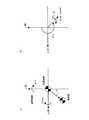
以下、図面を参照しながら本実施の形態1に係るロボットの制御方法について説明する。図1は、本実施の形態1に係る脚式ロボットの概要を示す図である。ロボット100は、胴体10と、胴体10に連結された2本の脚を有する。尚、図1には、一方の脚部20のみを示しており、他方の脚部は図示を省略している。胴体10は、ロボット100の動作(脚部の各関節の動作)を制御する制御部30と、胴体の加速度を検出する加速度センサ12と、胴体の10の鉛直方向に対する傾斜角(姿勢角)を検出する姿勢角センサ14を備える。 Hereinafter, the robot control method according to the first embodiment will be described with reference to the drawings. FIG. 1 is a diagram showing an outline of the legged robot according to the first embodiment. The
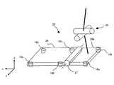
脚部20は、股関節21、膝関節23、足首関節25、大腿リンク22、脛リンク24、及び足部としての足平リンク26を備える。大腿リンク22と脛リンク24は、直線で模式化して示してある。股関節21は、胴体10と大腿リンク22を揺動可能に連結している。膝関節23は、大腿リンク22と脛リンク24を揺動可能に連結している。足首関節25は、脛リンク24と足平リンク26を揺動可能に連結している。脚部20の下端には足部としての足平リンク26が設けられる。足平リンク26は板状の部材であり、足平リンクの裏面(足裏面)は平面となっている。 The
足平リンク26には、距離検出部としての少なくとも3個以上の距離センサ16が設けられている。距離センサ16は、足平リンク26の裏面(足裏面)と接地面Sとの距離を検出する。図2は、足平リンク26の構成を説明するための図である。図2に示すように、足平リンク26は、上面視において、略矩形状に形成されている。足平リンク26の四隅近傍には、4つの距離センサ16a、16b、16c、16dがそれぞれ設けられている。ここでは、足平リンク26の爪先側に2つの距離センサ16a及び16dが、踵側に2つ距離センサ16b及び16cが設けられている。距離センサ16a及び16dは、足平リンク26の前方の所定位置における足裏面と接地面Sとの距離を検出し、距離センサ16b及び16cは、足平リンク26の後方の所定位置における足裏面と接地面Sとの距離を検出する。従って、距離センサ16a及び16dが検出する距離と16b及び16cが検出する距離の差から、足平リンク26の足裏面の接地面Sに対する傾きを求めることができる。 The
各関節には図示しないモータが内蔵されており、制御部30からの指令に基づいて駆動される。モータを駆動することによって、関節に連結されたリンク同士を揺動させることができる。図示を省略している他方の脚部も、脚部20と同様の構造を有する。制御部30が2本の脚部の関節(詳細には関節角)を適宜制御することにより、ロボット100を歩行させることができる。 Each joint incorporates a motor (not shown) and is driven based on a command from the
図1においては、説明の便宜上、ロボット100が進行する向き(前後方向)をx軸、ロボット100が進行する方向に対して水平方向に直交する向き(左右方向)をy軸、ロボット100の進行する平面から鉛直方向に延びる向き(上下方向)をz軸とし、これら3軸からなる絶対座標系を用いて説明する。即ち、図1において、x軸は紙面に向かって左右方向、y軸は紙面の奥行き方向、z軸は紙面中の上下方向を示す。尚、ロボット100の胴体10に対して点Obを特定し固定する。足平リンク26に対して点Ofを特定し固定する。 In FIG. 1, for convenience of explanation, the direction in which the
ロボット100は、制御部30に記憶されている歩容データに基づいて制御される。歩容データには、胴体10の目標位置(目標胴体位置)、胴体10の目標姿勢角(目標胴体姿勢角)、足平リンク26の目標位置(目標足平位置)、及び足平リンク26の目標姿勢角(目標足平姿勢角)のそれぞれの時系列データが含まれる。歩容データには、ロボット100が有する脚部のそれぞれの目標足平位置・姿勢角の時系列データが含まれる。 The
歩容データは、シミュレーション等によってロボット100を安定して歩行させることができるように作成されている。即ち、目標胴体位置、目標胴体姿勢角、目標足平位置、及び目標足平姿勢角は、ロボット100のZMP位置が接地面に接地した足裏で囲まれた凸包ないとなる関係を満足するように設定されている。作成された歩容データは、ロボット100の制御部30に記憶される。後述するように、制御部30は、歩容データに含まれる目標胴体位置等に実胴体位置等を一致させるように各関節を制御する。 The gait data is created so that the
目標胴体位置は、絶対座標系に対する特定点Obの位置で表される。特定点Obを原点とする胴体座標系を用いる場合には、目標胴体姿勢角は、絶対座標系に対する胴体座標系の傾きで表される。実胴体姿勢角は、胴体10に備えられた姿勢角センサ14によって検出することができる。目標足平位置は、絶対座標系に対する特定点Ofの位置で表される。目標足平姿勢角は、接地面に対する足裏面の角度で表される。特定点Ofを原点とする足平座標系を用いる場合には、目標足平姿勢角は、絶対座標系に対する足平座標系の傾きで表してもよい。実足平姿勢角は、後述するように、足平リンク26に備えられた距離センサ16によって検出することができる。 The target body position is represented by the position of the specific point Ob with respect to the absolute coordinate system. In the case of using a body coordinate system having the specific point Ob as the origin, the target body posture angle is represented by the inclination of the body coordinate system with respect to the absolute coordinate system. The actual body posture angle can be detected by a
続いて、制御部30の動作の詳細について説明する。制御部30は、倒立制御を実行すると共に、倣い制御を実行する。倒立制御は、実胴体位置及び実胴体姿勢角をそれぞれ目標胴体位置及び目標胴体姿勢角に一致する制御である。倣い制御は、接地面から見た相対的な実足平位置及び実足平姿勢角をそれぞれ目標足平位置及び目標足平姿勢角に一致する制御である。 Next, details of the operation of the
図3は、制御部30の機能構成を示す機能ブロック図である。制御部30は、歩容データを記憶する記憶部50と、記憶部50に記憶された歩容データを読み出す演算処理部60と、脚部20に含まれる各モータを駆動するモータ駆動部70と、を備えている。 FIG. 3 is a functional block diagram illustrating a functional configuration of the
記憶部50には、歩容データ(目標胴体位置、目標胴体姿勢角、目標足平位置、及び目標足平姿勢角の時系列データ)が記憶されている。歩容データ上で足裏が接地面と接触するときは、足裏面と接地面を面接触状態とするため、目標足平姿勢角(仮想的な接地面に対する仮想的な足裏面の傾き)はゼロに設定されている。また、歩容データ上の各目標値は、ロボット100のZMP位置が接地している脚の足裏で囲まれた凸包内となる関係を満たすように決定されている。 Gait data (target body position, target body posture angle, target foot position, and time series data of target foot posture angle) is stored in the
演算処理部60は、記憶部50に記憶された歩容データを読み出すと共に、読み出した歩容データによって特定されるロボット100の姿勢を実現するために必要な脚部20の関節角を算出する。そして、このように算出した関節角に基づく信号をモータ駆動部70に送信する。また、演算処理部60は、ロボット100に設けられた姿勢角センサ14や距離センサ16から信号を受けて、後述する倣い制御に用いる距離センサ16を選択する。さらにまた、演算処理部60は、センサからの信号を受けて、モータの駆動量を調整する。 The
より詳細には、演算処理部60は、倣い制御部61と、倒立制御部62と、距離センサ選択手段としての距離センサ選択部63と、歩容データ修正手段としての歩容データ修正部64と、逆キネマ演算部65と、を備える。制御部30内では、実胴体姿勢角と目標胴体姿勢角の偏差に基づくフィードバック制御系(倒立制御部62による倒立制御系)と、接地面から見た相対的な実足平姿勢角と目標足平姿勢角の偏差に基づくフィードバック制御系(倣い制御部61による倣い制御系)が含まれる。以下、倣い制御の偏差については、接地面から見た相対的な足平姿勢角に関するものを示すものとする。 More specifically, the
倒立制御部62は、ロボット100の胴体位置姿勢を目標位置姿勢に維持する機能を果たす。胴体位置姿勢は、実際の胴体位置と胴体姿勢角であり、目標位置姿勢は、目標の胴体位置と胴体姿勢角である。実胴体姿勢角は、胴体10に備えられた姿勢角センサ14で検出される。姿勢角センサ14は、例えば胴体10の角速度を検出するジャイロと、ジャイロの出力(角速度)を積分する積分器と、重力加速度ベクトルを検出する3軸加速度センサで構成される。転倒方向検出部(不図示)は、姿勢角センサ14の検出結果に基づいてロボット100の転倒方向を検出することができる。 The
倣い制御部61は、実足平姿勢角を目標足平姿勢角に一致させるように、例えば足裏が路面に密着している状態を目標とし、踵側が接地面から浮いている場合には、足平リンク26の爪先側を脛リンク24に近づける方向に足平リンク26を回転させる。即ち、足裏面と接地面との面接触を維持するように足平リンク26を回転させる。実足平姿勢角は、足平リンク26が備える距離センサ16a、16b、16c、16dの出力から求められる。ここで、距離センサ16は、後述する距離センサ選択部63により選択された距離センサを使用するものとする。距離検出部(不図示)は、距離センサ16の検出結果に基づいて、足裏と路面との距離を検出する。 The copying
距離センサ選択部63は、転倒方向検出部としての姿勢角センサ14、及び距離検出部としての距離センサ16の検出結果に基づいて、足裏と路面との距離を追従させるべき距離センサ16を選択する。距離センサ選択部63による距離センサ選択方法の詳細については後述する。 The distance
歩容データ修正部64は、距離センサ選択部63により選択された距離センサからの出力信号に基づいて、足裏と路面との位置関係が目標値に追従するように歩容データを修正する。まず、歩容データ修正部64は、選択された距離センサ16の出力値と追従すべき目標値との足偏差を計算する。そして、歩容データ修正部64は、計算された足偏差から、偏差に関する伝達関数を用いて、補正量を算出する。 The gait
より詳細には、以下のようにして記憶部50に記憶された歩容データ(目標胴体位置、目標胴体姿勢角、目標足平位置、及び目標足平姿勢角の時系列データ)が修正され、逆キネマティクス演算部65に入力される。 More specifically, the gait data (target body position, target body posture angle, target foot position, and target foot posture angle time series data) stored in the
記憶部50に記憶された目標足平位置は、目標足平位置と実足平位置の偏差に基づいて補正された後に逆キネマティクス演算部65に入力される。 The target foot position stored in the
記憶部50に記憶された目標胴体位置は、目標胴体加速度と実胴体加速度の偏差に基づいて補正された後に逆キネマティクス演算部65に入力される。目標胴体加速度は、目標胴体位置を2回微分することによって求められる。実胴体加速度は、加速度センサ12により検出される。 The target body position stored in the
記憶部50に記憶された目標胴体姿勢角は、そのまま逆キネマティクス演算部65に入力される。同時に、目標胴体姿勢角と実胴体姿勢角の偏差(胴体姿勢角偏差)が求められる。胴体姿勢角偏差は倒立制御部62に入力されて、胴体姿勢角偏差を小さくする方向に胴体を回転させる胴体補正角が算出される。実胴体姿勢角は、姿勢角センサ14により検出される。 The target body posture angle stored in the
記憶部50に記憶された目標足平姿勢角と実足平姿勢角の偏差(足平姿勢角偏差)が求められる。実足平姿勢角は、距離センサ選択部63により選択された距離センサ16により検出される。足平姿勢角偏差と上述した胴体補正角とが加算され、加算された結果が、倣い制御部61に入力される。倣い制御部61によって、入力された角度(胴体補正角と足平姿勢角偏差を加算した角度)を小さくする方向へ足平を回転させる足平補正角が求められる。記憶部50に記憶された目標足平姿勢角は、上述した足平補正角が加算された後に(足平補正角で補正された後に)逆キネマティクス演算部65に入力される。 A deviation between the desired foot posture angle and the actual foot posture angle stored in the storage unit 50 (foot posture angle deviation) is obtained. The actual foot posture angle is detected by the
逆キネマティクス演算部65には、以上のようにして修正された歩容データが入力される。これらの値から、逆キネマティクス演算部65では、逆キネマティクスの演算によって脚部20の各関節の目標関節角が算出される。ここで、それぞれの目標値は、絶対座標系に対する値で表されている。逆キネマティクス演算部65では、目標足平位置と目標胴体位置の差から足平と胴体の相対位置を計算し、目標足平姿勢角(足平補正角によって補正されている)と目標胴体姿勢角の差から足平と胴体の相対回転角を計算する。計算された相対位置と相対回転角を実現する目標関節角が算出される。 The inverse
モータ駆動部70は、演算処理部60により送信された目標関節角の信号に基づいて、脚部20を駆動するための各モータの駆動量を特定し、これらの駆動量でモータを駆動させるためのモータ駆動信号を各モータに送信する。これによって、脚部20の各関節における駆動量が変更され、ロボット100の動きが制御される。 The
続いて、図4を参照しながら、本実施の形態1に係るロボット100が行う制御処理について説明する。図4は、制御処理の概要を説明するためのフローチャートである。図4に示す制御処理に際しては、ロボット100は、不整地において、その足平リンク26の一部が障害物B上に接触しているものとする。図5は、ロボット100の足平リンク26の一部が障害物B上に接触した状態を説明するための図である。図5は、胴体10と脚部20を有する脚式ロボット100の模式的側面図である。尚、図5では、ロボット100の胴体10と脚部20のみを示しており、他方の脚部は図示を省略してある。足平リンク26には、4つの距離センサ16a、16b、16c、16dが設けられている。図5においては、図に示すx軸、y軸、z軸の3軸からなる絶対座標系を用いて説明する。 Next, a control process performed by the
図5においてロボット100に実現させたい全体位置姿勢を破線で示す。ロボット100は破線で示す目標位置姿勢とするため、矢印Cの方向へとその位置姿勢を制御しようとする。まず、転倒方向検出部は姿勢角センサ14の検出結果に基づいて、ロボット100の転倒方向を検出する(ステップS101)。転倒方向検出部は、胴体10の姿勢偏差又は胴体10の角速度などから転倒方向を検出することができる。例えば、胴体姿勢偏差(=目標姿勢から見た実姿勢)を計算することで、その胴体姿勢偏差を減らす方向の床反力モーメントを発生させるため、足平リンク26をどちらの方向に倣わせればよいのかを決定することができる。 In FIG. 5, the overall position and orientation to be realized by the
例えば、図6(a)に示すようにロボット100の実姿勢が目標姿勢に対して傾いている状態であるものとする。ここで、支持脚から見た目標姿勢に対する実姿勢の姿勢偏差ベクトル(ロール、ピッチ)を(legΔroll,legΔpitch)とする。そして、図6(b)に示すように、姿勢偏差ベクトル(legΔroll,legΔpitch)を用いて、次式を計算することで、姿勢偏差角θΔを求める。姿勢偏差角θΔを用いると、転倒方向をθΔ−π/2として表すことができる。図6に示す例では、姿勢偏差より、胴体10が左後方(矢印D)へと傾いていることを検知することができる。このように、ロボット100は、胴体姿勢偏差から転倒方向を検出することができる。
次いでロボット100は、ステップS101において検出した転倒方向に基づいて、センサを2個選択する(ステップS102)。図5に示すように、距離センサ16dの位置に障害物B(凸部)が存在する場合を想定する。この場合に、転倒方向に基づいて距離センサ16a、16b、16cを選択することとしては、凸部Bが障害となり距離センサ16a及び16cの出力値を同時に0とすることができないため、足裏を路面に倣わせることができない。このような場合には、胴体10の傾きを戻すことが可能な床反力モーメントを少なくとも発生させるべく、まず、転倒方向に基づいて、2個のセンサ16b、16cを選択するものとする。 Next, the
ここで、図7を用いて、転倒方向に基づいて、2個の距離センサを選択する方法について詳細に説明する。まず、距離センサ16を選択するための定数Θ1〜Θ4を、足裏と距離センサ16との位置関係から、以下の式に基づいて予め計算しておく。ここで、Xtは足平リンク26に設けられた距離センサ16dと16cの間の距離(距離センサ16aと16bの間の距離)であり、Ytは距離センサ16bと16cの間の距離(距離センサ16aと16dの間の距離)である。尚、定数Θ1〜Θ4は、atan2関数を用いて、−πからπまでの範囲において求める。
上記数2において計算された定数Θ1〜Θ4と、上記数1において計算された姿勢偏差角θΔを用いて、以下のようにして2個の距離センサを選択する。
Θ4≦θΔ−π/2≦Θ1(即ち、Θ4+π/2≦θΔ≦Θ1+π/2)の場合には、距離センサ16a及び16dの2個の距離センサを選択して有効とする。尚、選択されなかった距離センサは16b及び16cであり、後述するように、残り1個の距離センサをこれら残りの距離センサのうちから選択する。
Θ3≦θΔ−π/2≦Θ4(即ち、Θ3+π/2≦θΔ≦Θ4+π/2)の場合には、距離センサ16c及び16dの2個の距離センサを選択して有効とする。尚、選択されなかった距離センサは16a及び16bであり、後述するように、残り1個の距離センサをこれら残りの距離センサのうちから選択する。
Θ2≦θΔ−π/2≦Θ3(即ち、Θ2+π/2≦θΔ≦Θ3+π/2)の場合には、距離センサ16b及び16cの2個の距離センサを選択して有効とする。尚、選択されなかった距離センサは16a及び16dであり、後述するように、残り1個の距離センサをこれら残りの距離センサのうちから選択する。
Θ1≦θΔ−π/2≦π/2又は−3π/2≦θΔ−π/2≦Θ2(即ち、Θ1+π/2≦θΔ≦π又は−π≦θΔ≦Θ2+π/2)の場合には、距離センサ16a及び16bの2個の距離センサを選択して有効とする。尚、選択されなかった距離センサは16c及び16dであり、残り1個をこれら残りのセンサから選択する。Using the constants Θ1 to Θ4 calculated in Equation2 above and the attitude deviation angle θΔ calculated in Equation 1 above, two distance sensors are selected as follows.
In the case of Θ4 ≦ θΔ −π / 2 ≦ Θ1 (ie, Θ4 + π / 2 ≦ θΔ ≦ Θ1 + π / 2), the two
In the case of Θ3 ≦ θΔ −π / 2 ≦ Θ4 (that is, Θ3 + π / 2 ≦ θΔ ≦ Θ4 + π / 2), the two
In the case of Θ2 ≦ θΔ −π / 2 ≦ Θ3 (that is, Θ2 + π / 2 ≦ θΔ ≦ Θ3 + π / 2), two
Θ1 ≦ θΔ −π / 2 ≦ π / 2 or −3π / 2 ≦ θΔ −π / 2 ≦ Θ2 (ie, Θ1 + π / 2 ≦ θΔ ≦ π or −π ≦ θΔ ≦ Θ2 In the case of + π / 2), the two
図7において、例えば姿勢偏差ベクトルVから姿勢偏差角θΔを用いて、転倒方向Dを検出する。図においては、姿勢偏差角θΔは、Θ2≦θΔ−π/2≦Θ3(即ち、Θ2+π/2≦θΔ≦Θ3+π/2)を満足するため、距離センサ16b及び16cの2個の距離センサを選択して有効とする。このようにして距離センサを選択することで、転倒方向Dに基づいて、胴体10の傾きを戻すための床反力モーメントを効果的に得ることが可能な距離センサ16を2個選択することができる。尚、実装に際しては、ヒステリシス特性を持たせるように構成するとよい。これにより、姿勢偏差ベクトルがゼロ付近となる場合に発生するチャタリングを防止することができる。7, for example, from the attitude deviation vector V using the attitude error angle thetadelta, detecting the falling direction D. In the figure, the posture deviation angle θΔ satisfies Θ2 ≦ θΔ −π / 2 ≦ Θ3 (that is, Θ2 + π / 2 ≦ θΔ ≦ Θ3 + π / 2). Two
次いでロボット100は、ステップS102において選択されなかった残りの2個の距離センサ16のうち、足裏と路面との距離が小さな距離センサ16を1個選択する(ステップS103)。ステップS102において、4個の距離センサ16から2個の距離センサを選択した。本ステップS103においては、距離センサ16の出力値である計測高さに基づいて、ステップS102において選択されなかった残りの2個の距離センサ16から1個の距離センサを選択する。計測高さが小さな距離センサ16は、凸部側に位置する距離センサであるものと考えられる。このため、計測高さが小さな距離センサ16を選択して有効とすることで、路面の凹凸に関わらず、足平リンク26を路面に倣わせるように安定して制御することができる。尚、実装に際しては、ステップS102における距離センサ16の選択と同様にして、ヒステリシス特性を持たせるように構成するとよい。 Next, the
次いでロボット100は、ステップS102及びS103において選択された3個の距離センサ16から、足裏と路面との偏差である足偏差(ロール、ピッチ、z)を計算する(ステップS104)。ここで、足平リンク26の目標位置姿勢に対する実際の位置姿勢の足偏差(ロール、ピッチ、z)を(Δφ,Δθ,Δz)とする。尚、zは鉛直方向の計測高さを示す。例えば、3個の距離センサ16a、16b、16cが選択された場合には、次式で示す変換式を用いることで、足偏差を計算することができる。次式において示す変換行列によれば、足裏と距離センサ16が配置される位置の幾何学的関係から近似を用いて、各距離センサ16a乃至16dの出力値の偏差(Δz1,Δz2,Δz3,Δz4)と、各距離センサ16の偏差に対応する3行4列の変換行列とから、足偏差を一意に決定することができる。尚、選択された距離センサ16に応じて、変換行列における各要素の値は異なるものとする。
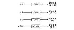
次いでロボット100は、ステップS104において計算された足偏差を用いて、実際に歩容データを補正するための足補正量を計算する(ステップS105)。足補正量の計算は、例えば、足偏差を入力とし、足補正量を出力とする伝達関数を通すことで実現することができる。図8は、足偏差を入力とし、足補正量を出力とする伝達関数を説明するための図である。図に示すように、足補正量(ロール)に関しては、ロール偏差Δφを伝達関数Cφ(s)に通す。足補正量(ピッチ)に関しては、ピッチ偏差Δθを伝達関数Cθ(s)に通す。足補正量(z)に関しては、z偏差Δzを伝達関数Cz(s)に通す。尚、使用する距離センサを切替える場合において足偏差が不連続となっている場合には、これらの伝達関数は、広域のゲインを小さくした特性を持つ伝達関数とすることが好ましい。Next, the
次いでロボット100は、ステップS105において計算された足補正量を実現するように歩容データを修正する(ステップS106)。そして、動作を続行する場合には、ステップS101へと戻り処理を続け、動作を終了する場合には処理を終了する。 Next, the
以上説明したようにロボット100の転倒方向を検出して、検出結果に基づいて目標値に追従させるべき3個の足裏距離センサ16を選択することで、ロボット100の体幹(胴体10)を倒立させるための床反力モーメントを効果的に得つつ、足裏と路面との接触を保つことができる。従って、支持脚を床面に密着させつつ、足裏からの床反力モーメントを得ることで、ロボット100の体幹を倒立させる安定化制御を容易に実行することができるため、不整地においてもロボット100は転倒せずに歩行することができる。 As described above, by detecting the falling direction of the
続いて、図9乃至11を参照しながら、本実施の形態1に係るロボット100が歩行動作中に行う制御処理について説明する。図9は、歩行動作中に、歩行動作パターンに応じて、ロボット100が距離センサの有効数を変更するようすを説明するための図である。図10は、ロボット100の脚部20が支持脚状態にある場合の制御処理の概要を説明するためのフローチャートである。図11は、ロボット100の脚部20が遊脚状態にある場合の制御処理の概要を説明するためのフローチャートである。 Subsequently, a control process performed during the walking motion of the
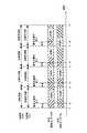
図9に示すように、ロボット100は、歩行動作パターンに応じて、足平リンク26に配置された距離センサのうち、有効とする距離センサの個数を変更する。ロボット100は、脚部20が支持脚の歩行動作パターンであるか、もしくは、遊脚の歩行動作パターンであるかを判定することができる。さらに、ロボット100は、支持脚が完全に着地したか否か、及び、遊脚が完全に離地したか否かを、例えば歩容データに基づいて検知するようにしてもよいし、距離センサ16の出力値から検知するようにしてもよい。 As shown in FIG. 9, the
脚部20が支持脚状態にある場合には、基本的には、足平リンク26に配置された距離センサのうち、3個の距離センサを有効とする(図9において、例えば左脚部20Lが支持脚状態であり、左足距離センサ16Lについてt2〜t3に示す区間)。また、脚部20が遊脚状態にある場合には、基本的には、全ての距離センサ(図では4個の距離センサ)を有効とする(図9において、例えば右脚部20Rが遊脚状態であり、右足距離センサ16Rについてt2〜t3に示す区間)。支持脚状態から遊脚状態へと脚部20が変化するまでの間は、最低限必要な個数の距離センサを有効とし、足裏が完全に離地して遊脚状態となった後は、全ての距離センサを有効とする(図9において、例えば左脚部20Lが支持脚状態であり、左足距離センサ16Lについてt3〜t4に示す区間)。遊脚状態から支持脚状態へと脚部20が変化するまでの間は、全ての距離センサを有効とし、足裏が完全に着地して支持脚状態となった後は、最低限必要な個数の距離センサ(図では3個の距離センサ)を有効とする(図9において、例えば右脚部20Rが遊脚状態であり、右足距離センサ16Rについてt3〜t4に示す区間)。ここで、時点t2及びt6は、支持脚であった右脚部20Rが完全に離地すると共に、遊脚であった左脚部20Lが完全に着地する時点を表す。時点t4及びt8は、遊脚であった右脚部20Rが完全に着地すると共に、支持脚であった左脚部20Lが完全に離地する時点を表す。When the
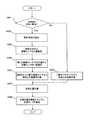
図10に示すフローチャートを用いて、ロボット100の脚部20が支持脚状態にある場合の制御処理を説明する。まず、ロボット100が歩行動作中に、いずれかの脚部20が遊脚状態から支持脚状態へと遷移する過程において、脚部20が完全に着地したか否かを判定する(ステップS201)。判定の結果、脚部20が完全に着地している場合(脚部20が支持脚状態となった場合)には、上述したように、3個の距離センサ16を選択する。即ち、ロボット100の転倒方向を検出する(ステップS202)。次いで、転倒方向に基づいて、2個の距離センサ16を選択する(ステップS203)。次いで、残りの距離センサ16から、足裏と路面との距離に基づいて1個の距離センサ16を選択する(ステップS204)。次いで、選択された3個の距離センサ16から、路面との足偏差を計算する(ステップS205)。 Control processing when the
一方、ステップS201における判定の結果、脚部20が完全に着地していない場合(脚部20が未だ支持脚状態となっていない場合)には、全ての距離センサ16を有効とし、全ての距離センサ16から、路面との足偏差を計算する(ステップS206)。例えば、4個の距離センサ16a、16b、16c、16d全てを有効とする場合には、次式で示す変換式を用いることで、足偏差を計算することができる。
次いで、ステップS205又はS206において計算された足偏差を用いて、実際に歩容データを補正するための足補正量を計算する(ステップS207)。次いで、ロボット100は、ステップS207において計算された足補正量を実現するように歩容データを修正する(ステップS208)。そして、動作を続行する場合には、ステップS201へと戻り処理を続け、動作を終了する場合には処理を終了する。 Next, a foot correction amount for actually correcting gait data is calculated using the foot deviation calculated in step S205 or S206 (step S207). Next, the
このように、足平リンク26が完全に路面に着地するまでの間は全てのセンサを有効とすることで、路面に対して速やかに倣わせることができる。このため、着地時の外乱をより効果的に抑制することができる。 In this manner, all the sensors are enabled until the
続いて、図11に示すフローチャートを用いて、ロボット100の脚部20が遊脚状態にある場合の制御処理を説明する。まず、ロボット100が歩行動作中に、いずれかの脚部20が支持脚状態から遊脚状態へと遷移する過程において、脚部20が完全に離地したか否かを判定する(ステップS301)。判定の結果、脚部20が完全に離地した場合(脚部20が遊脚状態となった場合)には、全ての距離センサ16を有効とし、上述したように、全ての距離センサ16から、路面との足偏差を計算する(ステップS302)。 Next, control processing when the
一方、ステップS301における判定の結果、脚部20が完全に離地していない場合(脚部20が未だ遊脚状態となっていない場合)には、上述したように、3個の距離センサ16を選択する。即ち、ロボット100の転倒方向を検出する(ステップS303)。次いで、転倒方向に基づいて、2個の距離センサ16を選択する(ステップS304)。次いで、残りの距離センサ16から、足裏と路面との距離に基づいて1個の距離センサ16を選択する(ステップS305)。次いで、選択された3個の距離センサ16から、路面との足偏差を計算する(ステップS306)。 On the other hand, as a result of the determination in step S301, when the
次いで、ステップS302又はS306において計算された足偏差を用いて、実際に歩容データを補正するための足補正量を計算する(ステップS307)。次いで、ロボット100は、ステップS307において計算された足補正量を実現するように歩容データを修正する(ステップS308)。そして、動作を続行する場合には、ステップS301へと戻り処理を続け、そうでない場合には処理を終了する。 Next, a foot correction amount for actually correcting the gait data is calculated using the foot deviation calculated in step S302 or S306 (step S307). Next, the
このように、遊脚が完全に離地するまでの間は足裏と路面とが接触しているため、3個の距離センサ16を選択して有効とすることで、支持脚の補正量を保持する。また、遊脚が完全に離地した後には全ての距離センサを選択して有効とすることで、遊脚が路面と接触した場合であっても路面を回避する方向へと速やかに倣うことができる。 Thus, since the sole and the road surface are in contact until the free leg completely leaves, the correction amount of the supporting leg can be set by selecting and enabling the three
発明の実施の形態2.
上述した実施の形態1においては、足平リンク26に設けられた距離センサ16が4個である場合について、それら距離センサ16のうち、転倒方向に基づいて、3個の距離センサを選択する処理について説明した。本発明はこれに限定されず、足平リンク26に設けられた少なくとも3個以上の距離センサから、転倒方向に基づいて、3個の距離センサを選択するようにしてもよい。尚、本実施の形態2に係るロボット100の構成は、足平リンク26の構成、及び足平リンク26に設けられる距離センサ16の配置を除いて、上述した発明の実施の形態1と同様である。Embodiment 2 of the Invention
In the above-described first embodiment, when there are four
図12は、本実施の形態2に係るロボット100の足平リンク26の構成を説明するための図である。足平リンク26は、爪先部26aと、爪先関節27を介して爪先部26aに連結された踵部26bとから構成される。ロボット100の歩行動作中には、爪先関節27を駆動することで、爪先部26aを路面に対して接地させたまま、踵部26bを浮かせることができる。即ち、踵部26bを浮かせたまま爪先部26aのみを接地させることにより、ロボット100を直立させることができる。 FIG. 12 is a diagram for explaining the configuration of the
図12に示すように、爪先部26a及び踵部26bは、上面視において、略矩形状に形成されている。爪先部26aの四隅近傍には、4つの距離センサ16a、16b、16c、16dがそれぞれ設けられている。ここでは、爪先部26aの爪先側に2つの距離センサ16a及び16dが、踵部方向側に2つ距離センサ16b及び16cが設けられている。距離センサ16a及び16dは、爪先部26aの前方の所定位置における足裏面と接地面Sとの距離を検出し、距離センサ16b及び16cは、爪先部26aの後方の所定位置における足裏面と接地面Sとの距離を検出する。踵部26bには、爪先部側とは反対側の二隅に2つの距離センサ16e及び16fがそれぞれ設けられている。距離センサ16e及び16fは、踵部26bの後方の所定位置における足裏面と接地面Sとの距離を検出する。従って、距離センサ16a及び16dが検出する距離と、距離センサ16b及び16cが検出する距離と、距離センサ16e及び16fが検出する距離との差から、足平リンク26の足裏面の接地面Sに対する傾きを求めることができる。 As shown in FIG. 12, the
本実施の形態2に係るロボット100は、爪先関節27を駆動させて爪先部26a及び踵部26bを路面に倣わせる際に、ロボット100の転倒方向に基づいて、爪先部26aに配置された距離センサ16から3個の距離センサ16を選択すると共に、踵部26bと路面との距離に基づいて、踵部26bに配置された距離センサ16から路面との距離を追従させるべき1個の距離センサ16を選択する。 The
続いて、図13乃至17を参照しながら、本実施の形態2に係るロボット100が歩行動作中に行う制御処理について説明する。図13は、歩行動作中に、歩行動作パターンに応じて、ロボット100が距離センサの有効数を変更するようすを説明するための図である。図14は、ロボット100の脚部20が支持脚状態にある場合の制御処理の概要を説明するためのフローチャートである。図15は、ロボット100の足平リンク26の爪先部26aの一部が障害物B上に接触した状態を説明するための図である。図16は、ロボット100の脚部20が遊脚状態にある場合の制御処理の概要を説明するためのフローチャートである。 Subsequently, a control process performed during the walking motion of the
図13に示すように、ロボット100は、歩行動作パターンに応じて、足平リンク26に配置された距離センサのうち、有効とする距離センサの個数を変更する。ロボット100は、脚部20が支持脚の歩行動作パターンであるか、もしくは、遊脚の歩行動作パターンであるかを判定することができる。さらに、ロボット100は、支持脚が完全に着地したか否か、及び、遊脚が完全に離地したか否かを、例えば歩容データに基づいて検知するようにしてもよいし、距離センサ16の出力値から検知するようにしてもよい。 As shown in FIG. 13, the
脚部20が支持脚状態にある場合には、基本的には、爪先部26aに配置された距離センサのうち、3個の距離センサを有効とする(図13において、例えば左脚部20Lが支持脚状態であり、左足距離センサ16Lについてt3〜t5に示す区間)。但し、爪先部26aに加えて、踵部26bも路面に接触している状態においては、爪先部26aに配置された距離センサ16から3個の距離センサ16を選択すると共に、踵部26bに配置された距離センサ16から1個の距離センサ16を選択し、合計4個の距離センサ16を有効とする(図13において、左足距離センサ16Lについて、例えばt2〜t3に示す区間)。尚、足平リンク26全体が路面に完全に接地して、脚部20が支持脚状態となるまでの間は、全ての距離センサ16(図では6個の距離センサ)を有効とする(図13において、左足距離センサ16Lについて、例えばt1〜t2に示す区間)。When the
脚部20が遊脚状態にある場合には、基本的には、全ての距離センサ16(図では6個の距離センサ)を有効とする(図13において、例えば右脚部20Rが遊脚状態であり、右足距離センサ16Rについてt2〜t5に示す区間)。但し、爪先部26a及び踵部26bの両方が路面に接触している状態においては、爪先部26aに配置された距離センサ16から3個の距離センサ16を選択すると共に、踵部26bに配置された距離センサ16から1個の距離センサ16を選択し、合計4個の距離センサ16を有効とする(図13において、右足距離センサ16Rについて、例えばt5〜t6に示す区間)。尚、爪先部26aが路面に接触しながら、踵部26bが浮いている状態においては、爪先部26aに配置された距離センサのうち、3個の距離センサを有効とする(図13において、右足距離センサ16Rについて、例えばt6〜t8に示す区間)。When the
このように、遊脚状態から支持脚状態へと脚部20が変化するまでの間は、始めは全ての距離センサを有効とするものとして、有効とする距離センサの個数を段階的に減少させ、足裏が完全に着地して支持脚状態となった後は、最低限必要な個数の距離センサ(図では3個の距離センサ)を有効とする(図13において、例えば右脚部20Rが遊脚状態から路面に完全に着地して支持脚状態となるまでの、右足距離センサ16Rについてt2〜t8に示す区間)。In this way, until the
尚、時点t2及びt8は、支持脚であった右脚部20Rが完全に離地すると共に、遊脚であった左脚部20Lが完全に着地する時点を表す。時点t5は、遊脚であった右脚部20Rが完全に着地すると共に、支持脚であった左脚部20Lが完全に離地する時点を表す。時点t3及びt5は、支持脚であった脚部20の踵部20bが完全に離地する時点を表す。Incidentally, the time t2 and t8, together with the right leg 20R has a support leg completely Hanarechi represents a time when the
図14に示すフローチャートを用いて、ロボット100の脚部20が支持脚状態にある場合の制御処理を説明する。図14に示す制御処理に際しては、ロボット100は、不整地において、その足平リンク26の一部が障害物B上に接触しているものとする。図15は、ロボット100の爪先部26aの一部が障害物B上に接触した状態を説明するための図である。図15においてロボット100に実現させたい全体位置姿勢を破線で示す。ロボット100は破線で示す目標位置姿勢とするため、矢印Cの方向へとその位置姿勢を制御しようとする。 A control process when the
まず、ロボット100が歩行動作中に、いずれかの脚部20が遊脚状態から支持脚状態へと遷移する過程において、脚部20が完全に着地したか否かを判定する(ステップS401)。判定の結果、脚部20が完全に着地している場合(脚部20が支持脚状態となった場合)には、爪先部26aに配置された4個の距離センサ16から、上述したように、3個の距離センサ16を選択する。即ち、ロボット100の転倒方向を検出する(ステップS402)。次いで、転倒方向に基づいて、爪先部26aに配置された4個の距離センサ16から、2個の距離センサ16を選択する(ステップS403)。次いで、爪先部26aに配置された残りの距離センサ16から、足裏と路面との距離に基づいて1個の距離センサ16を選択する(ステップS404)。尚、転倒方向に基づいて、爪先部26aに配置された4個の距離センサ16から3個の距離センサ16を選択する方法については、実施の形態1において足平リンク26に配置された4個の距離センサ16から3個の距離センサ16を選択する方法と同様であるため、ここでは説明を省略する。 First, it is determined whether or not the
次いで、踵部26bが路面と接触しておらず浮いた状態であるか否かを判定する(ステップS405)。判定の結果、踵部26bが路面と接触しておらず浮いた状態である場合(爪先部26aのみが路面と接触しており、つま先立ちしている状態)には、ステップS403及びS404において選択された3個の距離センサ16から、路面との足偏差を計算する(ステップS406)。ここで、爪先部26aの目標位置姿勢に対する実際の位置姿勢の足偏差(ロール、ピッチ、z)を(Δφ,Δθ,Δz)とする。尚、zは鉛直方向の計測高さを示す。例えば、3個の距離センサ16a、16b、16cが選択された場合には、次式で示す変換式を用いることで、足偏差を計算することができる。次式において示す変換行列によれば、足裏と距離センサ16が配置される位置の幾何学的関係から近似を用いて、各距離センサ16の出力値の偏差(Δz1,Δz2,Δz3,Δz4)と、各距離センサ16の偏差に対応する3行4列の変換行列とから、足偏差を一意に決定することができる。尚、選択された距離センサに応じて、変換行列における各要素の値は異なるものとする。
一方、判定の結果、踵部26bが路面と接触しており着地した状態である場合(爪先部26a及び踵部26bが路面と接触している状態)には、まず、踵部26bに配置された2個の距離センサ16から、足裏と路面との距離に基づいて1個の距離センサ16を選択する(ステップS407)。即ち、踵部26bに設けられた2個の距離センサ16e及び16fから、計測高さが小さな距離センサ16を選択する。 On the other hand, as a result of the determination, when the
次いで、ステップS403、S404、及びS407において選択された4個の距離センサ16から、路面との足偏差を計算する(ステップS408)。ここで、爪先部26aの目標位置姿勢に対する実際の位置姿勢の足偏差(ロール、ピッチ、z、つま先)を(Δφ,Δθ,Δz,Δθtoe)とする。尚、Δθtoeは爪先関節27に関して爪先部26aの回転角偏差を示す。例えば、爪先部26aから3個の距離センサ16a、16b、16cが選択され、踵部26bから1個の距離センサ16eが選択された場合には、次式で示す変換式を用いることで、足偏差を計算することができる。次式において示す変換行列によれば、足裏と距離センサ16が配置される位置の幾何学的関係から近似を用いて、各距離センサ16a乃至16fにそれぞれ対応する出力値の偏差(Δz1,Δz2,Δz3,Δz4,Δz5,Δz6)と、各距離センサ16の偏差に対応する4行6列の変換行列とから、足偏差を一意に決定することができる。尚、選択された距離センサに応じて、変換行列における各要素の値は異なるものとする。
一方、ステップS401における判定の結果、脚部20が完全に着地していない場合(脚部20が未だ支持脚状態となっていない場合)には、爪先部26a及び踵部26bに配置された全ての距離センサ16を有効とし、全ての距離センサ16から、路面との足偏差を計算する(ステップS409)。例えば、6個の距離センサ16a、16b、16c、16d、16e、16fの全てを有効とする場合には、次式で示す変換式を用いることで、足偏差を計算することができる。
次いで、ステップS406、S408、S409のいずれかにおいて計算された足偏差を用いて、実際に歩容データを補正するための足補正量を計算する(ステップS410)。足補正量の計算は、例えば、足偏差を入力とし、足補正量を出力とする伝達関数を通すことで実現することができる。図16は、足偏差を入力とし、足補正量を出力とする伝達関数を説明するための図である。図に示すように、足補正量(ロール)に関しては、ロール偏差Δφを伝達関数Cφ(s)に通す。足補正量(ピッチ)に関して、ロール偏差Δθを伝達関数Cθ(s)に通す。足補正量(z)に関して、ロール偏差Δzを伝達関数Cz(s)に通す。足補正量(つま先)に関して、つま先偏差Δθtoeを伝達関数Cθtoe(s)に通す。尚、使用する距離センサを切替える場合において足偏差が不連続となっている場合には、これらの伝達関数は、広域のゲインを小さくした特性を持つ伝達関数とすることが好ましい。Next, a foot correction amount for actually correcting the gait data is calculated using the foot deviation calculated in any of steps S406, S408, and S409 (step S410). The calculation of the foot correction amount can be realized, for example, by passing a transfer function having the foot deviation as an input and the foot correction amount as an output. FIG. 16 is a diagram for explaining a transfer function having a foot deviation as an input and a foot correction amount as an output. As shown in the figure, regarding the foot correction amount (roll), the roll deviation Δφ is passed through the transfer function Cφ (s). For the foot correction amount (pitch), the roll deviation Δθ is passed through the transfer function Cθ (s). For the foot correction amount (z), the roll deviation Δz is passed through the transfer function Cz (s). With respect to the foot correction amount (toe), the toe deviation Δθtoe is passed through the transfer function Cθtoe (s). If the foot deviation is discontinuous when the distance sensor to be used is switched, these transfer functions are preferably transfer functions having characteristics in which a wide-range gain is reduced.
次いで、ロボット100は、ステップS410において計算された足補正量を実現するように歩容データを修正する(ステップS411)。そして、動作を続行する場合には、ステップS401へと戻り処理を続け、動作を終了する場合には処理を終了する。 Next, the
脚部20が支持脚状態にある場合には、基本的には、爪先部26aに配置された距離センサのうち、3個の距離センサを有効とする。爪先部26aに加えて、踵部26bも路面に接触している状態においては、爪先部26aに配置された距離センサ16から3個の距離センサ16を選択すると共に、踵部26bに配置された距離センサ16から1個の距離センサ16を選択し、合計4個の距離センサ16を有効とする。足平リンク26全体が路面に完全に接地して、脚部20が支持脚状態となるまでの間は、全ての距離センサ16(図では6個の距離センサ)を有効とする。完全に路面に着地するまでの間は全てのセンサを有効とすることで、路面に対して速やかに倣わせることができる。このため、着地時の外乱をより効果的に抑制することができる。 When the
続いて、図17に示すフローチャートを用いて、ロボット100の脚部20が遊脚状態にある場合の制御処理を説明する。まず、ロボット100が歩行動作中に、いずれかの脚部20が支持脚状態から遊脚状態へと遷移する過程において、脚部20が完全に離地したか否かを判定する(ステップS501)。判定の結果、脚部20が完全に離地した場合(脚部20が遊脚状態となった場合)には、全ての距離センサ16を有効とし、上述したようにして、全ての距離センサ16から、路面との足偏差を計算する(ステップS502)。 Next, a control process when the
一方、ステップS501における判定の結果、脚部20が完全に離地していない場合(脚部20が未だ遊脚状態となっていない場合)には、爪先部26aに配置された4個の距離センサ16から、上述したようにして、3個の距離センサ16を選択する。即ち、ロボット100の転倒方向を検出する(ステップS503)。次いで、転倒方向に基づいて、爪先部26aに配置された4個の距離センサ16から、2個の距離センサ16を選択する(ステップS504)。次いで、爪先部26aに配置された残りの距離センサ16から、足裏と路面との距離に基づいて1個の距離センサ16を選択する(ステップS505)。尚、転倒方向に基づいて、爪先部26aに配置された4個の距離センサ16から3個の距離センサ16を選択する方法については、実施の形態1において足平リンク26に配置された4個の距離センサ16から3個の距離センサ16を選択する方法と同様であるため、ここでは説明を省略する。 On the other hand, if the result of determination in step S501 is that the
次いで、踵部26bが路面と接触しておらず浮いた状態であるか否かを判定する(ステップS506)。判定の結果、踵部26bが路面と接触しておらず浮いた状態である場合(爪先部26aのみが路面と接触しており、つま先立ちしている状態)には、ステップS504及びS505において選択された3個の距離センサ16から、路面との足偏差を計算する(ステップS507)。 Next, it is determined whether or not the
一方、判定の結果、踵部26bが路面と接触しており着地した状態である場合(爪先部26a及び踵部26bが路面と接触している状態)には、まず、踵部26bに配置された2個の距離センサ16から、足裏と路面との距離に基づいて1個の距離センサ16を選択する(ステップS508)。即ち、踵部26bに設けられた2個の距離センサ16e及び16fから、計測高さが小さな距離センサ16を選択する。次いで、ステップS504、S505、及びS508において選択された4個の距離センサ16から、路面との足偏差を計算する(ステップS509)。 On the other hand, as a result of the determination, when the
次いで、ステップS502、S507、S509のいずれかにおいて計算された足偏差を用いて、実際に歩容データを補正するための足補正量を計算する(ステップS510)。次いで、ロボット100は、ステップS510において計算された足補正量を実現するように歩容データを修正する(ステップS511)。そして、動作を続行する場合には、ステップS501へと戻り処理を続け、そうでない場合には処理を終了する。 Next, a foot correction amount for actually correcting the gait data is calculated using the foot deviation calculated in any of steps S502, S507, and S509 (step S510). Next, the
このように、遊脚が完全に離地するまでの間は足裏と路面とが接触しているため、3個の距離センサを選択して有効とすることで、支持脚の補正量を保持する。また、遊脚が完全に離地した後には全ての距離センサを選択して有効とすることで、遊脚が路面と接触した場合であっても路面を回避する方向へと速やかに倣うことができる。 In this way, since the sole and the road surface are in contact until the free leg completely leaves, the correction amount of the support leg is maintained by selecting and enabling three distance sensors. To do. In addition, by selecting and enabling all the distance sensors after the free leg has completely left the ground, even if the free leg comes into contact with the road surface, it can quickly follow the direction to avoid the road surface. it can.
以上説明したようにロボット100の転倒方向を検出して、検出結果に基づいて目標値に追従させるべき足裏距離センサ16を爪先部26aから3個選択すると共に、踵部26bから1個選択することで、ロボット100の体幹(胴体10)を倒立させるための床反力モーメントを効果的に得つつ、足裏と路面との接触を保つことができる。従って、支持脚を床面に密着させつつ、足裏からの床反力モーメントを受けてロボット100の体幹を倒立させる安定化制御を容易に実行することができるため、不整地においてもロボット100は転倒せずに歩行することができる。 As described above, the falling direction of the
その他の実施の形態.
上述した実施の形態においては、ロボット100は2本の脚を備えるものとしたが本発明はこれに限定されない。少なくとも2本以上の脚を有し、それぞれの脚の下端には足部が設けられ、足部の足裏には少なくとも3個以上の距離センサを備える脚式ロボットに対しても、本発明を適用することができる。Other embodiments.
In the embodiment described above, the
尚、本発明は上述した実施の形態のみに限定されるものではなく、既に述べた本発明の要旨を逸脱しない範囲において種々の変更が可能であることは勿論である。 It should be noted that the present invention is not limited to the above-described embodiment, and various modifications can be made without departing from the gist of the present invention already described.
10 胴体、
12 加速度センサ、14 姿勢角センサ、16 距離センサ
20 脚部、21 股関節、22 大腿リンク、23 膝関節、24 脛リンク、
25 足首関節、26 足平リンク、26a 爪先部、26b 踵部、27 爪先関節、
30 制御部、50 記憶部、
60 演算処理部、61 倣い制御部、62 倒立制御部、63 距離センサ選択部、
64 歩容データ修正部、65 逆キネマ演算部、
70 モータ駆動部、
100 ロボット10 torso,
12 acceleration sensors, 14 posture angle sensors, 16 distance sensors, 20 legs, 21 hip joints, 22 thigh links, 23 knee joints, 24 tibi links,
25 ankle joint, 26 foot link, 26a toe part, 26b buttocks, 27 toe joint,
30 control unit, 50 storage unit,
60 arithmetic processing units, 61 copying control unit, 62 inversion control unit, 63 distance sensor selection unit,
64 gait data correction unit, 65 inverse kinema calculation unit,
70 motor drive,
100 robot
Claims (7)
Translated fromJapanese前記距離検出部は、
前記足部の足裏に設けられた少なくとも4個の距離センサから構成され、
前記制御部が、
前記距離センサを選択する距離センサ選択手段と、
前記距離センサ選択手段により選択された距離センサの検出信号に基づいて、前記歩容データを修正する歩容データ修正手段と、を有し、
前記距離センサ選択手段が、
前記距離センサのうち、前記転倒方向検出部の検出結果に基づいて、前記転倒方向に近い位置に配置された第一及び第二の距離センサを選択し、選択されなかった前記距離センサのうち、前記足部の足裏と路面との距離が最も小さい距離センサを第三の距離センサとして選択する
ことを特徴とする脚式ロボット。A torso, a leg connected to the torso, a foot provided at a lower end of the leg, a fall direction detecting unit for detecting a fall direction of the torso, and a leg of the leg based on gait data A legged robot comprising: a control unit that drives and controls a joint; and a distance detection unit that detects a distance between a sole of the foot and a road surface,
The distance detector is
Consists of at least four distance sensors provided on the soles of the feet,
The control unit is
A distance sensor selecting means for selecting the distance sensor;
Gait data correcting means for correcting the gait data based on a detection signal of the distance sensor selected by the distance sensor selecting means,
The distance sensor selecting means is
Based on the detection result of the fall direction detection unit among the distance sensors, the first and second distance sensors arranged at positions close to the fall direction are selected, and among the distance sensors not selected, The legged robot characterized in that the distance sensor having the smallest distance between the sole of the foot and the road surface is selected as a third distance sensor.
前記脚部の歩行動作パターンが支持脚の歩行動作パターンであるか又は遊脚の歩行動作パターンであるかを判定し、判定結果に基づいて、前記距離センサ選択手段が選択する距離センサの個数を3個から全ての前記距離センサの個数の範囲で変更可能とする
ことを特徴とする請求項1記載の脚式ロボット。The control unit is
It is determined whether the walking motion pattern of the leg is a walking motion pattern of a supporting leg or a walking motion pattern of a free leg, and based on the determination result, the numberof distance sensors selected by the distance sensor selecting means is determined. The legged robot according to claim 1, wherein the legged robotcan be changed within a range of three to all of the distance sensors .
前記制御部が、
前記距離検出部の出力信号に基づいて、前記脚部の足裏が路面に完全に着地しているか否かを判定し、判定の結果、前記脚部の足裏が路面に完全に着地している場合には、前記距離センサ選択手段が、前記第一、前記第二、及び前記第三の距離センサを選択し、
前記判定の結果、前記脚部の足裏が路面に完全に着地していない場合には、前記距離センサ選択手段が、全ての前記距離センサを選択する
ことを特徴とする請求項1又は2記載の脚式ロボット。When the leg is a support leg,
The control unit is
Based on the output signal of the distance detection unit, it is determined whether or not the sole of the leg has completely landed on the road surface, and as a result of the determination, the sole of the leg has completely landed on the road surface. The distance sensor selecting means selects the first, second, and third distance sensors;
The distance sensor selection means selects all the distance sensors when the soles of the legs are not completely landed on the road surface as a result of the determination. Legged robot.
前記制御部が、
前記距離検出部の出力信号に基づいて、前記脚部の足裏が路面に完全に離地しているか否かを判定し、判定の結果、前記脚部の足裏が路面に完全に離地していない場合には、前記距離センサ選択手段が、前記第一、前記第二、及び前記第三の距離センサを選択し、
前記判定の結果、前記脚部の足裏が路面に完全に離地している場合には、前記距離センサ選択手段が、全ての前記距離センサを選択する
ことを特徴とする請求項1記載乃至3いずれか1項記載の脚式ロボット。When the leg is a free leg,
The control unit is
Based on the output signal of the distance detection unit, it is determined whether or not the sole of the leg is completely separated from the road surface. As a result of the determination, the sole of the leg is completely separated from the road surface. If not, the distance sensor selection means selects the first, second, and third distance sensors,
The distance sensor selection unit selects all the distance sensors when the soles of the legs are completely separated from the road surface as a result of the determination. 3. The legged robot according to any one of 3 above.
爪先部と、爪先関節と、当該爪先関節を介して前記爪先部に連結された踵部と、を備え、
前記距離検出部は、
前記爪先部の足裏に設けられた少なくとも4個の距離センサから構成され、
前記距離センサ選択手段は、
前記爪先部の足裏に設けられた距離センサのうち、前記転倒方向検出部の検出結果に基づいて、前記転倒方向に近い位置に配置された第一及び第二の距離センサを選択し、選択されなかった前記距離センサのうち、前記足部の足裏と路面との距離が最も小さい距離センサを第三の距離センサとして選択する
ことを特徴とする請求項1記載の脚式ロボット。The foot is
A toe part, a toe joint, and a heel part connected to the toe part via the toe joint,
The distance detector is
Consists of at least four distance sensors provided on the sole of the toe,
The distance sensor selection means includes
Of the distance sensors provided on the soles of the toes, select and select the first and second distance sensors arranged at positions close to the fall direction based on the detection result of the fall direction detection unit. The legged robot according to claim 1, wherein a distance sensor having a smallest distance between a sole of the foot and a road surface is selected as a third distance sensor among the distance sensors that have not been set.
前記爪先部の足裏に設けられた少なくとも4個の距離センサと、前記踵部の足裏に設けられた少なくとも2個の距離センサと、から構成され、
前記距離センサ選択手段は、
前記爪先部及び前記踵部が路面に接触している状態において、
前記爪先部の足裏に設けられた距離センサのうち、前記第一、前記第二、及び前記第三の距離センサを選択すると共に、
前記踵部の足裏に設けられた距離センサのうち、前記踵部の足裏と路面との距離が最も小さい距離センサを第四の距離センサとして選択する
ことを特徴とする請求項5に記載の脚式ロボット。The distance detector is
It is composed of at least four distance sensors provided on the sole of the toe portion and at least two distance sensors provided on the sole of the heel portion,
The distance sensor selection means includes
In the state where the toe portion and the heel portion are in contact with the road surface,
While selecting the first, the second, and the third distance sensor among the distance sensors provided on the sole of the toe,
The distance sensor with the smallest distance between the sole of the buttocks and the road surface is selected as the fourth distance sensor among the distance sensors provided on the soles of the buttocks. Legged robot.
歩容データに基づいて前記脚部の関節を駆動制御する制御ステップでは、
前記距離センサを選択する距離センサ選択ステップと、
選択された距離センサの検出信号に基づいて、前記歩容データを修正する歩容データ修正ステップと、を含み、
前記距離センサ選択ステップでは、
前記距離センサのうち、前記転倒方向検出部の検出結果に基づいて、前記転倒方向に近い位置に配置された第一及び第二の距離センサを選択し、選択されなかった前記距離センサのうち、前記足部の足裏と路面との距離が最も小さい距離センサを第三の距離センサとして選択する
ことを特徴とする脚式ロボットの制御方法。A torso, a leg connected to the torso, a foot provided at a lower end of the leg, a torsion direction detecting unit for detecting a torsion direction of the torso, and a sole and a road surface of the toe A control method for a legged robot comprising at least four distance sensors for detecting a distance,
In a control step of driving and controlling the joints of the legs based on gait data,
A distance sensor selection step of selecting the distance sensor;
A gait data correction step for correcting the gait data based on a detection signal of the selected distance sensor,
In the distance sensor selection step,
Based on the detection result of the fall direction detection unit among the distance sensors, the first and second distance sensors arranged at positions close to the fall direction are selected, and among the distance sensors not selected, A method for controlling a legged robot, wherein a distance sensor having the smallest distance between the sole of the foot and the road surface is selected as a third distance sensor.
Priority Applications (7)
| Application Number | Priority Date | Filing Date | Title |
|---|---|---|---|
| JP2007278107AJP4466715B2 (en) | 2007-10-25 | 2007-10-25 | Legged robot and control method thereof |
| PCT/IB2008/003245WO2009053838A2 (en) | 2007-10-25 | 2008-10-22 | Legged robot and control method of legged robot |
| EP08841605AEP2207645B1 (en) | 2007-10-25 | 2008-10-22 | Legged robot and control method of legged robot |
| KR1020097019951AKR101111714B1 (en) | 2007-10-25 | 2008-10-22 | Legged robot and control method of legged robot |
| AT08841605TATE516116T1 (en) | 2007-10-25 | 2008-10-22 | ROBOTS WITH LEGS AND CONTROL METHOD FOR ROBOTS WITH LEGS |
| CN2008801133215ACN101835569B (en) | 2007-10-25 | 2008-10-22 | Legged robot and control method of legged robot |
| US12/594,088US8172013B2 (en) | 2007-10-25 | 2008-10-22 | Legged robot and control method of legged robot |
Applications Claiming Priority (1)
| Application Number | Priority Date | Filing Date | Title |
|---|---|---|---|
| JP2007278107AJP4466715B2 (en) | 2007-10-25 | 2007-10-25 | Legged robot and control method thereof |
Publications (2)
| Publication Number | Publication Date |
|---|---|
| JP2009101498A JP2009101498A (en) | 2009-05-14 |
| JP4466715B2true JP4466715B2 (en) | 2010-05-26 |
Family
ID=40466936
Family Applications (1)
| Application Number | Title | Priority Date | Filing Date |
|---|---|---|---|
| JP2007278107AExpired - Fee RelatedJP4466715B2 (en) | 2007-10-25 | 2007-10-25 | Legged robot and control method thereof |
Country Status (7)
| Country | Link |
|---|---|
| US (1) | US8172013B2 (en) |
| EP (1) | EP2207645B1 (en) |
| JP (1) | JP4466715B2 (en) |
| KR (1) | KR101111714B1 (en) |
| CN (1) | CN101835569B (en) |
| AT (1) | ATE516116T1 (en) |
| WO (1) | WO2009053838A2 (en) |
Families Citing this family (36)
| Publication number | Priority date | Publication date | Assignee | Title |
|---|---|---|---|---|
| KR101709605B1 (en)* | 2009-07-01 | 2017-02-23 | 렉스 바이오닉스 리미티드 | Control system for a mobility aid |
| JP5659898B2 (en)* | 2011-03-22 | 2015-01-28 | トヨタ自動車株式会社 | Legged robot, its control method, and control program |
| CN102372042A (en)* | 2011-09-07 | 2012-03-14 | 广东工业大学 | A motion planning system for a biped robot |
| CN102541068A (en)* | 2011-12-27 | 2012-07-04 | 广东工业大学 | Lower limb motion planning system for biped robot in obstacle crossing |
| US9605952B2 (en)* | 2012-03-08 | 2017-03-28 | Quality Manufacturing Inc. | Touch sensitive robotic gripper |
| JP5959899B2 (en)* | 2012-03-30 | 2016-08-02 | 本田技研工業株式会社 | Contact state estimation device |
| CN104002887B (en)* | 2014-05-26 | 2017-07-25 | 上海大学 | Quick turn spherical robot |
| US9259838B1 (en)* | 2014-07-24 | 2016-02-16 | Google Inc. | Systems and methods for ground plane estimation |
| US10081098B1 (en) | 2014-08-25 | 2018-09-25 | Boston Dynamics, Inc. | Generalized coordinate surrogates for integrated estimation and control |
| US9618937B1 (en) | 2014-08-25 | 2017-04-11 | Google Inc. | Slip detection using robotic limbs |
| US9517561B2 (en)* | 2014-08-25 | 2016-12-13 | Google Inc. | Natural pitch and roll |
| US9387588B1 (en) | 2014-08-25 | 2016-07-12 | Google Inc. | Handling gait disturbances with asynchronous timing |
| US9446518B1 (en) | 2014-11-11 | 2016-09-20 | Google Inc. | Leg collision avoidance in a robotic device |
| US9499218B1 (en) | 2014-12-30 | 2016-11-22 | Google Inc. | Mechanically-timed footsteps for a robotic device |
| US9594377B1 (en) | 2015-05-12 | 2017-03-14 | Google Inc. | Auto-height swing adjustment |
| CN104816767B (en)* | 2015-05-21 | 2017-01-25 | 东南大学 | Bouncing robot capable of detecting obstacle height and distance and detection method |
| US9586316B1 (en) | 2015-09-15 | 2017-03-07 | Google Inc. | Determination of robotic step path |
| CN105203129B (en)* | 2015-10-13 | 2019-05-07 | 上海华测导航技术股份有限公司 | A kind of initial alignment method of inertial navigation device |
| US9778132B1 (en)* | 2015-12-16 | 2017-10-03 | X Development Llc | Methods and systems for force sensor calibration |
| US9925667B1 (en) | 2016-01-25 | 2018-03-27 | Boston Dynamics, Inc. | Continuous slip recovery |
| US9789919B1 (en) | 2016-03-22 | 2017-10-17 | Google Inc. | Mitigating sensor noise in legged robots |
| US10179619B1 (en)* | 2016-03-30 | 2019-01-15 | Schaft Inc. | Robotic foot sensor |
| CN105947012A (en)* | 2016-05-10 | 2016-09-21 | 南京航空航天大学 | Differential gear driving robot leg mechanism and control method |
| KR101820775B1 (en)* | 2016-05-27 | 2018-01-22 | (주)한국미래기술 | System for controlling foot landing of robot |
| JP6508167B2 (en)* | 2016-11-11 | 2019-05-08 | トヨタ自動車株式会社 | Walking training system |
| CN107380294A (en)* | 2017-03-31 | 2017-11-24 | 西华大学 | The bionical foot of quadruped robot |
| CN107861130A (en)* | 2017-11-28 | 2018-03-30 | 深圳市优必选科技有限公司 | A foot obstacle detection device and robot |
| CN109987169B (en)* | 2017-12-29 | 2021-01-08 | 深圳市优必选科技有限公司 | Gait control method and device for biped robot, terminal device and medium |
| CN109172091A (en)* | 2018-09-27 | 2019-01-11 | 南京市儿童医院 | A kind of ankle joint rehabilitation device |
| CN112947398B (en)* | 2019-12-11 | 2024-08-02 | 深圳市优必选科技股份有限公司 | Robot gait planning method and device, readable storage medium and robot |
| CN111924020B (en)* | 2020-08-11 | 2022-07-12 | 腾讯科技(深圳)有限公司 | Leg assemblies and equipment for robots |
| CN113753147B (en)* | 2021-09-29 | 2022-12-09 | 中国建筑第八工程局有限公司 | Overturn preventing device for profile steel self-climbing robot and overturn preventing method thereof |
| CN114610017B (en)* | 2022-01-27 | 2025-07-04 | 深圳鹏行智能研究有限公司 | A method for avoiding self-collision of a legged robot, a related device and a storage medium |
| CN115107900B (en)* | 2022-07-28 | 2023-04-18 | 南京信息工程大学 | Deformable foot end mechanism |
| CN115416002A (en)* | 2022-09-18 | 2022-12-02 | 美利威瑟(金华)科技发展有限责任公司 | Multifunctional exoskeleton system and application method |
| KR102631521B1 (en) | 2023-12-01 | 2024-01-31 | 주식회사세오 | Autonomous robots with floor detection device |
Family Cites Families (9)
| Publication number | Priority date | Publication date | Assignee | Title |
|---|---|---|---|---|
| JP2001353686A (en) | 2000-06-14 | 2001-12-25 | Sony Corp | Foot structure for leg type mobile robot and road surface detection apparatus |
| JP3726057B2 (en) | 2001-12-28 | 2005-12-14 | 本田技研工業株式会社 | Legged mobile robot and its floor reaction force detection device |
| JP3574952B2 (en) | 2002-02-18 | 2004-10-06 | 独立行政法人 科学技術振興機構 | Bipod walking type moving device and its walking control device |
| JP3569768B2 (en) | 2002-09-03 | 2004-09-29 | 独立行政法人 科学技術振興機構 | Biped walking device |
| US7236852B2 (en)* | 2002-10-11 | 2007-06-26 | Sony Corporation | Motion controlling apparatus and method and remote controlling apparatus and method for legged mobile robot |
| JP2004345024A (en) | 2003-05-22 | 2004-12-09 | Seiko Epson Corp | Leg structure of a legged walking robot and a legged walking robot having the same |
| KR100835361B1 (en)* | 2003-08-29 | 2008-06-04 | 삼성전자주식회사 | Walking Robot Using Simple Ground Reaction Sensor and Its Control Method |
| JP4513320B2 (en)* | 2003-12-17 | 2010-07-28 | ソニー株式会社 | Robot apparatus and motion control method of robot apparatus |
| KR100571829B1 (en) | 2004-02-06 | 2006-04-17 | 삼성전자주식회사 | Structure, foot structure and robot |
- 2007
- 2007-10-25JPJP2007278107Apatent/JP4466715B2/ennot_activeExpired - Fee Related
- 2008
- 2008-10-22CNCN2008801133215Apatent/CN101835569B/ennot_activeExpired - Fee Related
- 2008-10-22KRKR1020097019951Apatent/KR101111714B1/ennot_activeExpired - Fee Related
- 2008-10-22EPEP08841605Apatent/EP2207645B1/ennot_activeNot-in-force
- 2008-10-22USUS12/594,088patent/US8172013B2/ennot_activeExpired - Fee Related
- 2008-10-22ATAT08841605Tpatent/ATE516116T1/ennot_activeIP Right Cessation
- 2008-10-22WOPCT/IB2008/003245patent/WO2009053838A2/enactiveApplication Filing
Also Published As
| Publication number | Publication date |
|---|---|
| CN101835569A (en) | 2010-09-15 |
| JP2009101498A (en) | 2009-05-14 |
| WO2009053838A3 (en) | 2009-06-11 |
| CN101835569B (en) | 2012-02-08 |
| WO2009053838A2 (en) | 2009-04-30 |
| ATE516116T1 (en) | 2011-07-15 |
| EP2207645B1 (en) | 2011-07-13 |
| EP2207645A2 (en) | 2010-07-21 |
| KR101111714B1 (en) | 2012-02-16 |
| KR20090119984A (en) | 2009-11-23 |
| US20100126785A1 (en) | 2010-05-27 |
| US8172013B2 (en) | 2012-05-08 |
Similar Documents
| Publication | Publication Date | Title |
|---|---|---|
| JP4466715B2 (en) | Legged robot and control method thereof | |
| US5355064A (en) | Control system for legged mobile robot | |
| US8793019B2 (en) | Control device for legged mobile robot | |
| EP1120203B1 (en) | Controller for legged mobile robot | |
| JP3629133B2 (en) | Control device for legged mobile robot | |
| KR101687630B1 (en) | Walking robot and method for controlling balancing the same | |
| JPH05337849A (en) | Posture stabilization controller for a legged mobile robot | |
| JP2001322076A (en) | Floor shape estimation device for legged mobile robot | |
| WO1998033629A1 (en) | Leg type mobile robot control apparatus | |
| KR20130095973A (en) | Walking robot and control method thereof | |
| WO2001087549A1 (en) | Floor shape deducing device for legged mobile robot | |
| JP3270766B2 (en) | Control device for legged mobile robot | |
| JP5040693B2 (en) | Legged robot and control method thereof | |
| JP2008119764A (en) | Control device for biped robot | |
| JPH11300661A (en) | Control device for legged mobile robot | |
| JP2008093762A (en) | Walking robot | |
| JP5659898B2 (en) | Legged robot, its control method, and control program | |
| JP2009255231A (en) | Walking control device and walking control method | |
| JP2009101497A (en) | Legged robot and control method thereof | |
| JP5228589B2 (en) | Legged robot and control method thereof | |
| JP2009184034A (en) | Legged robot and control method thereof | |
| JP4237130B2 (en) | Control device for legged mobile robot | |
| JP4696728B2 (en) | Legged robot and its control method | |
| JP3071032B2 (en) | Control device for legged mobile robot | |
| JP2009125838A (en) | Biped walking robot and walking control method |
Legal Events
| Date | Code | Title | Description |
|---|---|---|---|
| A131 | Notification of reasons for refusal | Free format text:JAPANESE INTERMEDIATE CODE: A131 Effective date:20090901 | |
| A521 | Request for written amendment filed | Free format text:JAPANESE INTERMEDIATE CODE: A523 Effective date:20090924 | |
| A131 | Notification of reasons for refusal | Free format text:JAPANESE INTERMEDIATE CODE: A131 Effective date:20091208 | |
| A521 | Request for written amendment filed | Free format text:JAPANESE INTERMEDIATE CODE: A523 Effective date:20100108 | |
| TRDD | Decision of grant or rejection written | ||
| A01 | Written decision to grant a patent or to grant a registration (utility model) | Free format text:JAPANESE INTERMEDIATE CODE: A01 Effective date:20100202 | |
| A01 | Written decision to grant a patent or to grant a registration (utility model) | Free format text:JAPANESE INTERMEDIATE CODE: A01 | |
| A61 | First payment of annual fees (during grant procedure) | Free format text:JAPANESE INTERMEDIATE CODE: A61 Effective date:20100215 | |
| FPAY | Renewal fee payment (event date is renewal date of database) | Free format text:PAYMENT UNTIL: 20130305 Year of fee payment:3 | |
| FPAY | Renewal fee payment (event date is renewal date of database) | Free format text:PAYMENT UNTIL: 20130305 Year of fee payment:3 | |
| FPAY | Renewal fee payment (event date is renewal date of database) | Free format text:PAYMENT UNTIL: 20140305 Year of fee payment:4 | |
| LAPS | Cancellation because of no payment of annual fees |