JP4466108B2 - Certificate issuance method and certificate verification method - Google Patents
Certificate issuance method and certificate verification methodDownload PDFInfo
- Publication number
- JP4466108B2 JP4466108B2JP2004035902AJP2004035902AJP4466108B2JP 4466108 B2JP4466108 B2JP 4466108B2JP 2004035902 AJP2004035902 AJP 2004035902AJP 2004035902 AJP2004035902 AJP 2004035902AJP 4466108 B2JP4466108 B2JP 4466108B2
- Authority
- JP
- Japan
- Prior art keywords
- certificate
- mount
- color
- individual information
- pattern
- Prior art date
- Legal status (The legal status is an assumption and is not a legal conclusion. Google has not performed a legal analysis and makes no representation as to the accuracy of the status listed.)
- Expired - Lifetime
Links
Images


Classifications
- G—PHYSICS
- G09—EDUCATION; CRYPTOGRAPHY; DISPLAY; ADVERTISING; SEALS
- G09C—CIPHERING OR DECIPHERING APPARATUS FOR CRYPTOGRAPHIC OR OTHER PURPOSES INVOLVING THE NEED FOR SECRECY
- G09C5/00—Ciphering apparatus or methods not provided for in the preceding groups, e.g. involving the concealment or deformation of graphic data such as designs, written or printed messages
- G—PHYSICS
- G07—CHECKING-DEVICES
- G07D—HANDLING OF COINS OR VALUABLE PAPERS, e.g. TESTING, SORTING BY DENOMINATIONS, COUNTING, DISPENSING, CHANGING OR DEPOSITING
- G07D7/00—Testing specially adapted to determine the identity or genuineness of valuable papers or for segregating those which are unacceptable, e.g. banknotes that are alien to a currency
- G07D7/20—Testing patterns thereon
- G07D7/202—Testing patterns thereon using pattern matching
- G07D7/2033—Matching unique patterns, i.e. patterns that are unique to each individual paper
Landscapes
- Engineering & Computer Science (AREA)
- Physics & Mathematics (AREA)
- General Physics & Mathematics (AREA)
- Computer Vision & Pattern Recognition (AREA)
- Theoretical Computer Science (AREA)
- Credit Cards Or The Like (AREA)
- Record Information Processing For Printing (AREA)
- Management, Administration, Business Operations System, And Electronic Commerce (AREA)
Description
Translated fromJapanese本発明は、証明書(certificate)を作成する技術および証明書を検証(verify)する技術に関する。特に、オンラインで交付された証明書データを利用者のプリンタで印刷することを可能とする証明書発行方法と、検証者が証明書発行者に問い合わせをすることなく印刷物の真贋を検証することを可能とする証明書検証方法に関する。 本発明は、ソフトウエアを含む製品の取引を、ネットワークを利用して仲介するための技術に関する。その中でも特に、取引において、製品を供給する者(組織)もしくはこの製品を特定するための技術に関する。 The present invention relates to a technique for creating a certificate and a technique for verifying the certificate. In particular, a certificate issuance method that allows the certificate data issued online to be printed on the user's printer, and that the verifier verifies the authenticity of the printed matter without contacting the certificate issuer. It relates to a certificate verification method that can be performed. The present invention relates to a technique for mediating transactions of products including software using a network. In particular, the present invention relates to a person (organization) supplying a product or a technology for specifying the product in a transaction.
電子証明書に関する従来技術には、以下のものがある。例えば、特許文献1のように,印刷物の真贋や有効性確認をオフラインで行なうものがある。また、特許文献2のように,証明を求める申請者側でプリントした印刷物を公的証明書として使用するものがある。さらに、特許文献3のように,個人を特定することができる情報と証明書データを関連付けて管理するデータベースと、キー情報をもとにして証明書データを検索する技術もある。 The prior art related to electronic certificates includes the following. For example, as disclosed in Japanese Patent Application Laid-Open No. H10-260260, there is an apparatus that performs the authenticity and validity check of a printed matter offline. In addition, as disclosed in Patent Document 2, there is one that uses a printed matter printed on the side of an applicant seeking certification as a public certificate. Further, as disclosed in Patent Document 3, there is a technique for searching certificate data based on key information and a database for managing information that can identify an individual and certificate data in association with each other.
本発明の第1の目的は、特殊な用紙や特殊な印刷装置を使うことなく、一定の機能を満たすプリンタであれば、該プリンタからオンラインで証明書を発行できるシステムや方法を提供することである。 A first object of the present invention is to provide a system and method that can issue a certificate online from a printer that satisfies certain functions without using special paper or a special printing device. is there.
本発明の第2の目的は、検証者が簡単に証明書の有効性を検証できるシステムや方法を提供することである。 A second object of the present invention is to provide a system and a method by which a verifier can easily verify the validity of a certificate.
本発明は、これらの目的を達成するための証明書を発行する方法であって,証明書発行依頼者の個別情報(individual information)を入力し,証明書毎に異なる背景パターンを部分的にもつ台紙(board)の電子データを作成し,前記台紙の電子データの背景パターン上に個別情報を文字で上書きし,背景パターンと上書き文字との関係を台紙上に記入し,前記電子データを証明書としてプリントするステップを含む。 The present invention is a method for issuing a certificate for achieving these objects, and inputs individual information (individual information) of a certificate issuer and has a different background pattern for each certificate. Create electronic data on the board, overwrite individual information with characters on the background pattern of the electronic data on the board, fill in the relationship between the background pattern and the overwritten characters on the board, and certificate the electronic data As a printing step.
また,証明書の検証する方法であって,証明書を電子データに変換し,証明書上の背景パターンと上書き文字との関係を読み出し,証明書から背景パターン上に個別情報が文字で上書きされている領域を抽出し,該領域の背景パターンと文字が前記読み出した関係を満足しているか否かをチェックし,満足していないときに証明書は無効であると判断するステップを含む。 Also, it is a method for verifying a certificate, converting the certificate into electronic data, reading the relationship between the background pattern on the certificate and the overwritten character, and overwriting the individual information with characters on the background pattern from the certificate. And a step of checking whether the background pattern and characters of the area satisfy the read relationship and determining that the certificate is invalid if not satisfied.
本発明によれば、特殊なプリンタ、用紙を使用しなくとも、証明書を発行可能とできる。 According to the present invention, it is possible to issue a certificate without using a special printer or paper.
以下、本発明の実施例を詳細に説明する。まず、第1の実施例について、説明する。 Hereinafter, embodiments of the present invention will be described in detail. First, the first embodiment will be described.
(1) システム構成
図2は、証明書発行および検証システムの接続関係を示すシステム構成図であり,証明書を発行する証明書発行システム200,証明書の台紙を作成する台紙発行システム210,証明書の発行を依頼する依頼者システム220,証明書の有効性を検証する検証者システム230を含む。図2に示す各システムは、コンピュータであり、記憶媒体に格納されるプログラムをメモリに読み出し、プロセッサでプログラムに従った処理を実行する。(1) System Configuration FIG. 2 is a system configuration diagram showing the connection relationship between the certificate issuance and verification system. The
証明書発行システム200と台紙発行システム210と依頼者システム220とはネットワーク240で繋がっている。検証者システム230はネットワーク240と常時接続している必要はないが,検証のレベルにより接続できる事が望ましい。 The certificate issuing
これらのシステムは,論理的な装置であり,証明書発行システム200と台紙発行システム210は,同じコンピュータで実現されても良い。さらに,証明書発行システム200が依頼者システム220を含んでも良い。 These systems are logical devices, and the certificate issuing
図10は証明書発行システム200の構成図である。証明書発行システム200は,CPU1000,通信制御装置1010,メインメモリ1020,ディスク装置1030,バス1040を含む。ディスク装置1030は,個々の証明書発行のためのデータ1031−1037をテーブルの形で記憶し,証明書発行プログラムを記憶する。証明書発行プログラムは、メインメモリ1020にロードされ,CPU1000によって実行される。 FIG. 10 is a configuration diagram of the certificate issuing
図9は台紙発行システム210の構成図である。台紙発行システム210は,CPU900,通信制御装置910,メインメモリ920,ディスク装置930,バス940を含む。ディスク装置930は,個々の台紙発行のためのデータ931−936をテーブルの形で記憶し,台紙発行プログラムを記憶する。台紙発行プログラムは、メインメモリ920にロードされ,CPU900によって実行される。 FIG. 9 is a configuration diagram of the mount issuing
図12は依頼者システム220の構成図である。依頼者システム220は,CPU1200,通信制御装置1210,メインメモリ1220,キーボードやスキャナなどの入力装置1240,表示装置1250,プリンタなどの出力装置1260,バス1230を含む。 FIG. 12 is a configuration diagram of the
図11は検証者システム230の構成図である。検証者システム230は,CPU1100,通信制御装置1110,メインメモリ1120,ディスク装置1130,バス1140,スキャナなどの入力装置1150を含む。ディスク装置1030は,証明書検証のためのデータ1131−1134をテーブルの形で記憶してもよく,さらに検証プログラムを記憶する。検証プログラムは、メインメモリ1120にロードされ,CPU1100によって実行される。 FIG. 11 is a configuration diagram of the
(2)証明書
図1は、オンライン発行される証明書の例を示した説明図である。図1の証明書100は、免許証(driving license)を例にしたものである。通常、証明書100には、顔写真を貼る領域110、住所などの個人に関係したデータを記載する領域120、許可証の種類や有効期限を記載する領域130、それ以外の部分に発行部署の代表者の署名や印が記載されている。その他の証明書の例として,営業許可証,身分証明書,パスポートがあり,証明書により,記載されるデータは異なる。(2) Certificate FIG. 1 is an explanatory diagram showing an example of a certificate issued online. The
図3及び図4は、図1に偽造防止のために加えるデータを示した説明図である。 3 and 4 are explanatory diagrams showing data added to prevent forgery in FIG.
図3について説明する。図3では、図1で示したデータ領域以外の領域に、文字情報を記載する領域300とコード情報を書き込む領域330を設けている。ここで、文字情報とは英数・かな・漢字等の文字で表現された情報であり、人間が直接に読み取ることができるが、コード情報とはバーコードや2次元コードのような情報処理装置を使って読み取ることができる情報を指す。 With reference to FIG. In FIG. 3, an
なお、2次元コードとは、バーコードを積み重ねたスタック型と、同じ大きさの
セルを黒白で縦横に配置したマトリックス型がある。これら以外の2次元バーコードおよびそれと同様に情報を記録するコードであっても良い。さらに、電子透かしのように紙面全体に目立たないように情報を記録しても良い。The two-dimensional code includes a stack type in which barcodes are stacked and a matrix type in which cells of the same size are arranged vertically and horizontally in black and white. Other than these, a two-dimensional bar code and a code for recording information in the same manner may be used. Further, information may be recorded so as not to be conspicuous on the entire paper surface like a digital watermark.
また、文字情報を記載する領域300とコード情報を書き込む領域330は、それぞれ2つの領域に分けられている。1つの領域310と340には、台紙を管理する為の台紙ID、台紙発行時刻及び台紙発行時の署名等のデータが台紙発行システム210によって文字とコードでそれぞれ記載される。もう1つの領域320と350には、個別情報書き込み時の署名,検証のためのデータ等のデータが証明書発行システム200によって文字とコードでそれぞれ記載される。 The
図4は、図1の領域120と領域130に台紙発行システム210によって施される処理を示した説明図である。台紙発行システム210において、台紙ID,台紙発行時刻及び台紙発行時の署名データ等のデータ400をコード化し、領域120に書き込んだ時のイメージを示すものである。このイメージを背景として,文字情報が上書きされる。 FIG. 4 is an explanatory diagram showing processing performed by the mount issuing
領域120の一部領域410を拡大すると、黒いドットとして表示される画素420と、空白として表現される画素430とがある。例えば、文字が8ビットで表現されるとしたとき、このデータを16進数で表現すると2桁になる。16進数1桁を4ドット×4ドットの四角で表現し,四角内に1つの黒ドットの位置で0から15の値を表す。したがって,四角2つ(32ドット)で1文字を表現することができる。データ400は、複数の文字列で構成されるので、上記の方法でコード化すると領域120は410に示すパターンで塗潰される。ここでは、データ400を単純にコード化する例を述べたが、データの偽造を防ぐため、データ400を暗号化した上で、コード化しても良い。また、領域全体をパターンで埋めるためにデータを繰り返し記載しても良い。ちなみに上書きされる文字の大きさは,1文字120ドット×120ドットであるが,他の大きさの文字であってもよい。 When a
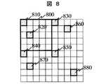
図8は、領域120,130の背景パターンの他の例の説明図である。図8では、塗潰し領域を5ドット×5ドットの四角800に分割し、そのマトリックスの左上の画素(810,830,840,850)が16進コードの分割基準点として必ず塗潰されるものとする。そして,四角800内の右下の16ドットを前述の4×4の四角に対応させる。このようにすると、文字列の情報は画素820,860,870,880のように無秩序に分布することになるが、基準点である画素810,830,840,850は規則的に配列される為、データの検出が容易になる。 FIG. 8 is an explanatory diagram of another example of the background pattern of the
図5は、コード化したパターンで領域を塗潰す方法について示した例の説明図である。データ510の内容をコード化して,繰り返し領域120を塗潰す場合、同じパターンを何度も繰り返し使うことになる。例えば、パターン520とパターン530が同じだと分かってしまうと、パターン520の一部が上書き文字によって消されたとしても、パターン530を使って上書き文字を消し去ることが可能になる。これを防止する方法として、内容510を暗号化する為に台紙発行システム210が数種類の秘密鍵を用意し、秘密鍵1(550)で暗号化した暗号データ1を作成し、これをコード化したパターンを領域520に描く。さらに、暗号データ1を秘密鍵2(560)で暗号化した暗号データ2を作成し、これをコード化したパターンを領域530に描く。このような処理を繰り返すことによって領域120を塗潰す。このようにすると、領域520を塗潰したパターンと領域530を塗潰したパターンは異なることになるので、前記のような不正はできなくなる。図5では,秘密鍵k+1の代わりに埋め込みID 580を使用した演算処理を行っているが,この埋め込みIDは一種の乱数である。 FIG. 5 is an explanatory diagram of an example showing a method of filling a region with a coded pattern. When the content of the
秘密鍵は1つであっても良いし,2つの秘密鍵を交代に使用しても良い。埋め込みIDは使用しなくても良い。 There may be only one secret key, or two secret keys may be used alternately. The embedded ID may not be used.
(3)証明書の発行
図6は、証明書をオンラインで発行するプロセスを示す基本的な処理フローである。(3) Certificate Issuance FIG. 6 is a basic processing flow showing a process for issuing a certificate online.
依頼者システム220は,証明書の要求者から,住所,氏名,写真などの個人情報を受け付ける。依頼者システム220は,個人認証を行う装置を持っていても良い。依頼者システム220は,受け付けた個人情報と証明書の種類と有効期限などのデータを含む,個別情報を電子データの形で証明書発行システム200に送信する。 The
証明書発行システム200は、図6のステップ600において、依頼者システム220から証明書発行依頼を受け付ける。そして、証明書発行システム200は、ステップ610において、台紙発行システム210に対して証明書の種類を特定して,台紙の発行を依頼する。 The
ステップ610の依頼に対し、台紙発行システム210は、台紙を発行するだびに,システムでユニークな台紙IDを生成する。例えば、台紙IDは証明書の種類を示すコードとその証明書種類のもとでの員数(sequential number)の連結(concatenation)である。さらに台紙IDは,乱数などを含んでもよい。 In response to the request in
台紙発行システム210は、ステップ620において、台紙の作成を行なう。すなわち、図1に示した台紙データを電子的に作成する。さらに、図3における領域310及び領域340に台紙IDや台紙の発行時刻及び台紙発行時の署名データを文字とコードでそれぞれ記入する。台紙発行時の署名データとは,典型的には,台紙IDと台紙の発行時刻の連結データのハッシュ値を台紙発行システム210の秘密鍵で暗号化したデータである。また、前述の方式で領域120及び領域130の背景パターンを記入する。 In
台紙発行システム210は,図9に示すディスク装置930に台紙発行時の情報を台紙ID毎に記憶する。ディスク装置930には台紙ID931,台紙の発行時刻932、台紙発行時の署名データ933が格納される。また、台紙に付いている属性情報も、有効期限データ934、用途の識別データ935として記憶される。さらに、図4あるいは図5において説明した背景データ作成に使用する暗号鍵も領域936に記憶されても良い。 The
次に、台紙発行システム210は、ステップ630(図6)において、員数の更新を行なう。 Next, the
台紙発行システム210は、ステップ640において、発行した台紙データ(電子データ)を、通信制御装置910を使って証明書発行システム200に送信する。 In
証明書発行システム200は、ステップ650において通信制御装置1010経由で台紙データを受け取り、該台紙データに個別情報を記入する。すなわち,領域110に画像を添付、領域120及び領域130に個別情報(住所,氏名,有効期限など)を文字で上書きする。画像110には、台紙ID等の情報を電子透かし技術を用いて挿入する。 また,領域120及び領域130上の(文字上書き前の)黒ドットの総数,および同領域への文字上書きの際に文字によってつぶされた黒ドットの総数,およびその座標を検証のためのデータとして記録しておく。
さらに,図3における領域320及び領域350に個別情報の署名データと前記検証のためのデータを文字とコードでそれぞれ記入する。個別情報の署名データとは,典型的には,個別情報のハッシュ値を証明書発行システム200の秘密鍵で暗号化したデータである。検証のためのデータは,コードでのみ記入された方が良い。In
Further, the signature data of the individual information and the verification data are written in the
証明書発行システム200は,図10に示すディスク装置1030に証明書発行時の情報を証明書毎に記憶する。ディスク装置1030には証明書発行時刻1031,個別情報1032、個別情報のハッシュ値1033,個別情報の署名データ1034が格納される。また、ディスク装置1030には、台紙の情報を管理する領域もあり、台紙ID1036、台紙発行システムから送られてきた台紙データ1037が記録されている。さらに,図5の背景パターン作成時に使用した埋め込みIDを台紙発行システムから受け取って,領域1035に記憶しても良い。 The
依頼者システム220は、ステップ660(図6)において、通信制御装置1210を用いて証明書データ(電子データ)を入手し、表示装置1250に表示することができる。また、ステップ670において、証明書データを出力装置1260に送り、紙に印刷する。 In step 660 (FIG. 6), the
ところで、台紙発行システム210はステップ620において、図4あるいは図5のイメージの台紙を作成するが、台紙発行時には領域310及び領域340にも台紙ID等の情報が記録される。すなわち、領域310及び領域340に記録された情報によって、領域120や領域130のドットパターンが生成されるのであれば、ドットパターンを印刷しなくても上書きした文字との重なりを検出することができる。したがって、ステップ620の台紙作成処理は、個別情報を上書きする領域120や領域130に対して、実際にドットパターンを印刷する処理を含まなくても良い。 By the way, the
(4)証明書の検証
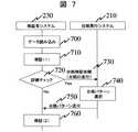
図7は証明書の真贋を検証するプロセスを示すものである。検証者システム230は、ステップ700において、スキャナ1150を用いて印刷物である証明書の読み込みを行なう。そして、ステップ710において、検証者システム内でのローカルな検証(検証(1))を行なう。(4) Certificate Verification FIG. 7 shows a process for verifying the authenticity of a certificate. In
証明書を偽造する場合によく行われる方法として,(a)現在書かれている文字(個別情報)を消して別の文字を書く,(b)現在書かれている文字に加筆して別の文字にする,がある。証明書には,検証のためのデータとして,領域120及び領域130上の(文字上書き前の)黒ドットの総数,および同領域への文字上書きの際に文字によってつぶされた黒ドットの総数,およびその座標が,領域350にコードで記入されている。 Common methods for forging a certificate include (a) deleting the current character (individual information) and writing another character, (b) adding another character to the current character. There is a character. The certificate includes, as data for verification, the total number of black dots (before overwriting characters) on the
ステップ700で,検証者システム230は、読みこんだ証明書の領域120及び領域130の背景パターンの黒ドットの数を数え,領域350上の検証のためのデータと比較する。比較の結果両者が不一致ならば,検証者システム230は証明書を無効と判断する。この処理により,上述の偽造をかなりの確率で検出できる。さらに,検証者システム230は、検証のためのデータ内の文字によってつぶされた黒ドットの座標と,読みこんだ証明書の領域120及び領域130の文字位置を比較する事により, さらに高い確率で偽造を検出できる。 In
さらに,高いレベルの検証が必要とされる場合(720),検証者システム230はネットワーク240に接続して,以下の検証(検証(2))のいずれか,いくつか,または全部を行う。 Further, if a high level of verification is required (720), the
ケース1:検証者システム230は,読みこんだ証明書の領域310から台紙IDを抽出し,台紙発行システム210に台紙IDを送付して,台紙検証依頼をする(ステップ730)。台紙発行システム210は,記憶しているデータから背景パターンを復元して,検証者システム230に送付する(ステップ730)。検証者システム230は,読みこんだ証明書の背景パターンと台紙発行システムから送られてきた背景パターンが文字以外の部分で一致する事を確認する(ステップ760)。これにより,背景パターンが偽造された場合を検出できる。 Case 1: The
ケース2:検証者システム230は,読みこんだ証明書の領域300または330から署名データを抽出し,台紙発行システム210および証明書発行システム200の公開鍵を入手して,署名データを検証する。これは,良く知られた電子署名の検証方法である。公開鍵を検証者システム230のディスク装置1130に記憶して置いても良い。この検証は上述の検証(1)とともに行われても良い。 Case 2: The
ケース3:これは,領域120,130の背景パターンが図5による同じ1セットのデータを繰り返し使用したパターンで作成されており,あらかじめ定められた領域の1セットのデータ分のパターンには,文字が上書きされていない場合にのみ適応できる。検証者システム230は,読みこんだ証明書の領域120および130からあらかじめ定められた領域の1セットのデータ分のパターンを抽出する。図5で使用した埋め込みIDおよび図5で使用した秘密鍵に対応する公開鍵と抽出したパターンを使用して,図5の方法とは逆の方法で,領域120と130の背景パターンを復元できる。読みこんだ背景パターンと復元した背景パターンを比較する事により,背景パターンの偽造を検出できる。このときに使用する復号鍵を検証者システム230のディスク装置1130に記憶して置いても良い。 Case 3: This is because the background pattern of the
次に、第2の実施例について説明する。 Next, a second embodiment will be described.
(1) 証明書の発行
この実施例は,台紙発行システムと証明書発行システムが,同じ1つのシステム(台紙・証明書発行システムとする)として実現される。また,証明書の領域120及び領域130の背景パターンの作成方法が実施例1とは異なる。背景パターンに複数の色を使用することに加え,背景パターンが個別情報により変わる。その他の部分は,実施例1と同じである。(1) Certificate Issuance In this embodiment, the mount issuing system and the certificate issuing system are realized as the same system (the mount / certificate issuing system). Also, the background pattern creation method of the
図13及び図14は、領域120及び領域130を塗潰すパターンの生成方法に関するフローチャートである。最初に基本となるパターンの生成方法について簡単に述べる。基本パターンとして、領域内にある画素を3色(色1,色2,色3)で塗り分けたものを作成する。このとき、上・下・左・右で隣り合う画素が必ず異なる色となるように塗り分ける。最も簡単な塗り方は、色1及び色2及び色3を順番に繰り返し塗っていくことであり、最上段を横一列に塗り分ける。次に、一つ下の列について、色2を最左端として、色2,色3,色1の順に繰り返し塗潰す。さらに、その下の列については、色3を最左端として、色3,色1,色2の順に繰り返し塗潰す。これを最下列まで繰り返せば、領域120及び領域130を3色で塗潰すことができる。これを基本パターンと呼ぶ。なお、この色は、プリンタで用いられる原色をそれぞれ用いてもよい。例えば、シアン、マゼンダ、イエロー、ブラックから3色を選択してもよいし、3色に限定せず4色を用いてもよい。 13 and 14 are flowcharts relating to a method for generating a pattern for filling the
次に、基本パターンに台紙IDや個別情報等を埋め込む処理を行なう。この処理を示すのが図13である。 Next, a process of embedding the mount ID and individual information in the basic pattern is performed. This process is shown in FIG.
台紙・証明書発行システムは、ステップ1300において領域120あるいは領域130をスキャンするための初期値設定を行なう。例えば、左上の画素を初期値と設定する。ステップ1310において、対象画素の左に位置する画素と真上に位置する画素に関して画素色を調べる。この2つの画素の色が同じであればステップ1315に処理を進め、異なる場合はステップ1350に処理を進める。 The mount / certificate issuing system performs initial value setting for scanning the
ステップ1315では,台紙・証明書発行システムは、画素に対して情報を埋め込むかどうかを判定する。例えば、台紙IDが“11”であり、この台紙IDを画像中に埋め込むこととする。ところで、“11”は10進法で表現されたものであるが、これを2進数で表現すると“1011”となる。したがって、“11”という値を画素に埋め込むためには少なくとも4つの画素が必要となり、4つの画素にそれぞれ“1”,“0”,“1”,“1”を埋め込む。ステップ1315に戻り、対象となっている画素に埋め込もうとしている値が“1”であるか“0”であるかを調べ、“1”であった場合はステップ1320に進み、“0”であった場合はステップ1350に進む。ステップ1320では、対象となっている画素の左側の画素及び真上の画素の色を調べその色が色3であったなら、ステップ1325において対象画素を色2で塗潰す。 In
色3でなく、色1であった場合はステップ1330で判定し、ステップ1335において対象画素を色3で塗潰す。色3でも色1でもない場合は、必然的に色2であるから、ステップ1340において対象画素を色1で塗潰す。ステップ1350は、情報を埋め込むことができない画素の色決めに関する処理であり、図14において説明する。 If it is not color 3 but color 1, it is determined in
そして、対象画素の色が決まったならば、ステップ1360においてスキャンする画素を一つだけ右に移動する。ただし、最右端であればステップ1365において、ステップ1370に進み、それ以外の時はステップ1305に戻る。同様に、ステップ1370では、スキャンする画素を一列だけ下段に移動し、ステップ1375において最下段であれば処理を終了するが、それ以外のときはステップ1305に戻って処理を継続する。 When the color of the target pixel is determined, in
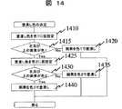
図14は、ステップ1350について詳細に示したフローである。台紙・証明書発行システムは、ステップ1410において、対象画素の塗潰し色を色1に仮設定する。ステップ1415において、対象画素の左側と真上の画素に関して色を調べ、その両方ともが色1でなければ(すなわち、両方とも色2、両方とも色3、1つが色2でもう1つが色3)、対象画素を色1で塗潰す。ステップ1415において少なくとも1つが色1であった場合は、ステップ1425において塗潰し色を色2に仮設定する。そして、ステップ1430において前述と同様に色を調べ、対象画素の左側と真上の画素が色2でなければ、ステップ1435において対象画素を色2で塗潰す。ステップ1430において色2が含まれる場合は、対象画素の左側と真上の画素のどちらかが色1であり、残りが色2ということであるから、ステップ1440において対象画素を色3で塗潰す。このような処理を行なうことで、隣り合う画素は必ず異なる色で塗潰すというルールを守った上で、基本パターンに個別の情報を埋め込むことができる。 FIG. 14 is a flowchart showing details of
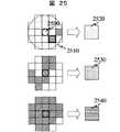
図15は、このようにして作成した台紙のパターン例である。この台紙パターンの上に個別情報を文字で上書きし,さらにそのコードまたはハッシュ値を背景パターンに埋め込む。図26はこの台紙の上に日本文字「う」という字を上書きし、さらに「う」のコードまたはハッシュ値を台紙に埋め込んだ例を示す図である。 FIG. 15 shows an example of a mount pattern created in this way. The individual information is overwritten with characters on the mount pattern, and the code or hash value is embedded in the background pattern. FIG. 26 is a diagram showing an example in which the Japanese character “u” is overwritten on the mount, and the code or hash value of “u” is embedded in the mount.
図15において、領域1500の画素1510は色1、画素1520は色2、画素1530は色3で塗られており、隣り合う画素は異なる色で塗潰されている。図26において、画素1560には文字が重なっている。さらに,図15において色1に塗られた部分1580に「う」という文字のコード情報を埋め込んだ例である。 In FIG. 15, a
図16に、台紙の背景パターンに対してさらにコード情報を埋め込む処理のフローを示す。ステップ1600において、台紙データを読み込み、台紙上に個別データの文字等を上書きする(ステップ1610)。この時点で、画素1560のような文字と重なった画素は文字の色(たとえば黒)で塗潰す。 FIG. 16 shows a flow of processing for embedding code information in the background pattern of the mount. In
ステップ1620において、例えば領域の最左上の画素を初期値として設定し
、ステップ1640において、その対象画素が色1(ここでは色1を空白と表現
)であるかどうかを判定する。色1であった場合は、埋め込もうとしている個別データを図13の説明で述べたのと同じ方法で埋め込む。すなわち、ステップ1650において、埋め込む値が0であれば塗潰し色はそのままとし、埋め込む値が1であれば塗潰し色を色4とする。In
そして、対象画素の色が決まったならば、ステップ1660においてスキャンする画素を一つだけ右に移動する。ただし、最右端であればステップ1670において、ステップ1680に進み、それ以外の時はステップ1630に戻る。同様に、ステップ1680では、スキャンする画素を一列だけ下段に移動し、ステップ1690において最下段であれば処理を終了するが、それ以外のときはステップ1630に戻って処理を継続する。 If the color of the target pixel is determined, in
この例では,1文字上書きして,1文字分のコード情報を背景パターンに埋め込んだが,すべての文字情報を上書きした後に,そのハッシュ値を繰り返し,背景パターンに埋め込んでも良い。 In this example, one character is overwritten and the code information for one character is embedded in the background pattern. However, after all the character information is overwritten, the hash value may be repeated and embedded in the background pattern.
この例は,実施例1で作成した検証のためのデータの作成や証明書への該データの記載を行わない。 In this example, the data for verification created in the first embodiment is not created and the data is not described in the certificate.
(2)証明書の検証
検証者システム230では,以下のような検証を行う。電子署名の検証は,本実施例でも同様に行う事ができる。検証者システム230は,読みこんだ証明書を抽出して台紙・証明書発行システムへ送信し,検証を依頼する。台紙・証明書発行システムは,台紙ID毎に保存してある領域120,130のパターンと文字情報を,送信されてきた証明書と比較し,一致するか否かを調べ,検証者システムに結果を送信する。(2) Certificate Verification The
次に、第3の実施例について、説明する。 Next, a third embodiment will be described.
(1)証明書の発行
この実施例は,台紙発行システムと証明書発行システムが,同じ1つのシステム(台紙・証明書発行システムとする)として実現される。また,領域120及び領域130の背景パターンの作成方法が実施例1とは異なる。背景パターンに複数の色を使用することに加え,背景パターンが個別情報により変わる。(1) Certificate Issuance In this embodiment, the mount issuance system and the certificate issuance system are realized as the same system (the mount / certificate issuance system). Also, the background pattern creation method for the
この実施例では,証明書の領域120,130の上に,最初に文字を書き,その後背景を複数の色で塗りつぶしていく。 In this embodiment, characters are first written on the
図18は、最初に書かれた文字の局所的な形状から周囲の塗潰し色を決めるためのルールを示した図である。最初に,文字の書かれた領域120,130を2×2の画素からなる矩形に分割する。 FIG. 18 is a diagram showing a rule for determining the surrounding paint color from the local shape of the character written first. First, the
図18は、文字部分を含む2×2の画素からパターン1810,とそのパターン内のまだ塗られていない画素の塗潰し色番号1800の関係を示した表である。2×2の画素からなる矩形を単位とした場合、矩形が文字によって塗潰されるパターンは14通りとなる。このなかで、4つの画素すべてが塗潰された場合と、一つも塗潰されていない場合を除いた12通りを4つに分類する。例えば、パターン1821、パターン1822、パターン1823に対応する色を1820とし、パターン1831、パターン1832、パターン1833に対応する色を1830とし、パターン1841、パターン1842、パターン1843に対応する色を1840とし、パターン1851、パターン1852、パターン1853に対応する色を1850とする。 FIG. 18 is a table showing a relationship between a
このルールを日本文字「の」という文字に適用した例を図19に示す。このとき、図19の矩形1910はパターン1821と同じであるから、空白部を色1820で塗潰す。また、矩形1920はパターン1852と同じであるから、空白部を色1850で塗潰す。さらに、矩形1930はパターン1842と同じであるから、空白部を色1840で塗潰す。このようにして文字「の」の周辺を塗潰すと図19となる。 FIG. 19 shows an example in which this rule is applied to the Japanese character “NO”. At this time, since the
図20は、さらに塗潰されていない部分の色を決めるために、領域を4×4の画素の矩形で分割し、前記と同じルールで塗潰す色をきめたものである。例えば、矩形2010はパターン1822と同じになるから、色1820で塗潰し、矩形2020はパターン1821と同じになるから色1820で塗潰す。 In FIG. 20, in order to further determine the color of the unfilled portion, the area is divided into 4 × 4 pixel rectangles, and the colors to be painted are determined according to the same rule as described above. For example, since the rectangle 2010 is the same as the
もし,全領域が塗りつぶされていない場合は,同様に,領域を8×8の画素の矩形に分割・塗りつぶし,領域を16×16の画素の矩形に分割・塗りつぶしと繰り返す。 If the entire area is not filled, similarly, the area is divided and filled into 8 × 8 pixel rectangles, and the area is divided into 16 × 16 pixel rectangles and filled.
次に,前述の方法で塗りつぶした領域に更に,台紙IDなどの情報を埋め込む。ここでは,実施例1の図4に示したコード化情報を埋め込むと仮定する。 Next, information such as a mount ID is further embedded in the area painted by the above-described method. Here, it is assumed that the coded information shown in FIG.
図4におけるドットパターンが図17の画素1710や画素1720に相当する。これらの画素1710や画素1720を用いてボロノイ図を作成する。
ボロノイ図は良く知られた領域の分割方法であって,以下の様に作成する。領域上の隣接する2つの点を線でむすび,その線を2分する点でその線に直交する直線を引く。すべての点について,この操作を繰り返すと,図17のように,領域が分割される。ボロノイ図を作成すると、パターンに含まれる各ドットについて、1つのドットを含む閉領域を定義することができる。The dot pattern in FIG. 4 corresponds to the pixel 1710 and the
The Voronoi diagram is a well-known method for dividing an area, and is created as follows. Connect two adjacent points on the area with a line, and draw a straight line perpendicular to the line at the point that bisects the line. If this operation is repeated for all points, the region is divided as shown in FIG. When a Voronoi diagram is created, a closed region including one dot can be defined for each dot included in the pattern.
図17と図20を重ね合わせると図21になる。 When FIG. 17 and FIG. 20 are overlapped, FIG. 21 is obtained.
さらに,図21の閉領域内を閉領域内のドットの色で塗りつぶす。もし,画素2260のように対象画素と文字が重なっている場合は,対象画素から最も近い距離にある画素の色で塗り潰す。図22は、このようにして文字以外の領域を塗潰したものである。このように、文字の周囲が4色の色で塗り分けられる。 Further, the inside of the closed region in FIG. 21 is filled with the color of the dots in the closed region. If the target pixel and the character overlap as in the pixel 2260, the pixel is painted with the color of the pixel closest to the target pixel. FIG. 22 shows the area other than the characters painted out in this way. In this way, the periphery of the character is painted with four colors.
このようにして,台紙・証明書発行システムは証明書の領域120,130を作成する。 In this way, the mount / certificate issuing system creates
図18の塗りつぶしルールに変わる別のルールを図25に示す。図25では,対象画素の周囲のどの程度が文字によって塗潰されているかで色を決める。対象画素2500の周囲2510において、30%未満であれば色2520、30%以上60%未満であれば色2530、60%以上であれば色2540を塗潰し色とする。後は,図21,22に説明した方法で証明書の領域120,130を作成する。 Another rule that replaces the fill rule of FIG. 18 is shown in FIG. In FIG. 25, the color is determined depending on how much of the periphery of the target pixel is filled with characters. In the
(2)証明書の検証
検証者システム230では,以下のような検証を行う。電子署名の検証は,本実施例でも同様に行う事ができる。検証者システム230は,読みこんだ証明書の領域120,130の文字を抽出して,図18,19,20(あるいは,図25)で説明した方法で背景を塗りつぶす。次に,検証者システム230は,台紙IDを台紙・証明書発行システムへ送信し,図4のドットパターンを台紙・証明書発行システムから入手する。検証者システム230は,入手したドットパターンを使用して,図21,22に説明した方法で背景を塗り替え,プリンタに出力する。証明書の領域120,130の色パターンとプリンタから出力された色パターンを目視で比べる事により,証明書の偽造を検出できる。検証者システム230が両色パターンの比較を行い,一致・不一致のみを出力しても良い。(2) Certificate Verification The
本実施例の変形例として,証明書作成時に図4のドットパターンの座標情報をコード化して,証明書の領域330に記載しておいても良い。この場合,証明書の検証時に,検証者システムは,台紙・証明書発行システムに接続することなく,証明書上の情報から,上述の検証を行う事ができる。 As a modification of the present embodiment, the dot pattern coordinate information of FIG. 4 may be coded and written in the
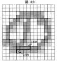
偽造の一例を示す。図23は文字「の」の一部を改竄したものであり、例えば領域2300を塗潰して、文字を偽造している。この文字に関して図18のルールを適用すると、ドット2310は色1840で塗潰される。そして、ボロノイ図で表現された領域の塗りわけを行なったものが図24である。図22では、ドット2230とドット2250は同じ色であり、境界線2270の両側が同じ色1850で塗潰される。一方,図24では、ドット2430とドット2450が異なるから、境界線の左側が色1840、右側が色1850となる。したがって、図22と図24の違いが目視でも判別できる。このような色の変化は、文字の形の一部を改竄した場合だけでなく、位置を少しずらしただけでも起こりうる。 An example of forgery is shown. In FIG. 23, a part of the character “NO” is falsified. For example, the
本発明は、証明書の発行を、コンピュータを用いて実現することが可能になる。 According to the present invention, it is possible to issue a certificate using a computer.
200…証明書発行者システム、210…台紙発行者/管理者システム、220…依頼者システム、230…検証者システム、900…制御手段、910…通信手段、920…一時記憶手段(メモリ)、930…蓄積手段、931…電子台紙ID、932…台紙発行時刻データ、933…台紙発行時署名データ、934…有効期限データ、935…用途識別データ、936…暗号鍵、1000…制御手段、1010…通信手段、1020…一時記憶装置(メモリ)、1031…証明内容記入時刻データ、1032…証明内容データ、1033…証明内容特徴量、1034…証明内容記入時署名データ、1036…電子台紙ID、1037…台紙データ、1100…制御手段、1110…通信装置、1120…一時記憶装置、1130…蓄積手段、1131…電子台紙ID、1132…台紙発行者の塗潰しパターン、1133…証明書発行者の塗潰しルール、1134…復号鍵、1150…入力手段(スキャナ)、1200…制御手段、1210…通信手段、1220…一時記憶手段、1240…入力手段(キーボード)、1250…表示手段(ディスプレイ)、1260…出力手段(プリンタ)
200 ... Certificate issuer system, 210 ... Mount issuer / administrator system, 220 ... Requester system, 230 ... Verifier system, 900 ... Control means, 910 ... Communication means, 920 ... Temporary storage means (memory), 930 ... Storage means, 931... Electronic mount ID, 932. Mount issue time data, 933... Mount data signature data, 934. Expiration date data, 935... Application identification data, 936.
Claims (7)
Translated fromJapanese証明書発行依頼者の個別情報を入力し,
台紙の電子データに個別情報を文字で書き,
予め決められた第1のルールに従って,文字で書かれた個別情報の背景部分を複数の色で塗りつぶし,
予め決められた第2のルールに従って,文字で書かれた個別情報の背景部分を前記証明書の台紙を識別する台紙IDを埋め込み更に塗り替えることで,前記背景部分が前記台紙IDにより変化するようにし,
証明書識別番号と前記台紙IDを対応付けて記憶し,
証明書識別番号を台紙の電子データに記入し,
前記電子データを証明書としてプリントする,
ステップを含む。A method of issuing a certificate using a computer,
Enter the individual information of the certificate issuer,
Write individual information in text on the electronic data on the mount,
In accordance with a predetermined first rule, the background portion of the individual information written in letters is painted in multiple colors,
According to a predetermined second rule,by the background portion of the individual information written in charactersmay exchangeembedding further coatingthe base sheet ID for identifying the base sheet of thecertificate,the background portion is changed by the mount ID Like
Storing the certificate identification number and themount ID in association with each other ;
Enter the certificate identification number in the electronic data on the mount,
Printing the electronic data as a certificate,
Includes steps.
前記予め決められた第1のルールは,背景部分を等面積の矩形に分割し,矩形内の塗り潰された部分の位置と塗り潰されていない部分の色の対応を規定する。The certificate issuance method according toclaim 1 ,
The first predetermined rule divides the background portion into equal-area rectangles, and defines the correspondence between the position of the filled portion in the rectangle and the color of the unfilled portion.
前記証明書毎に異なる情報は,コード化されドットで表現したパターンに変換され,
前記予め決められた第2のルールは,第1のルールに従って塗った背景部分と該パターンの重なるドットの位置と色を抽出し,該ドットの位置を使用してボロノイ図を作成し,
該色でボロノイ図の各領域を規定する。The certificate issuing method according toclaim 2 ,
Information that differs for each certificate is converted into a pattern that is encoded and expressed in dots,
The second predetermined rule is to extract the position and color of the dot that overlaps the background portion and the pattern painted according to the first rule, and create a Voronoi diagram using the position of the dot,
Each color defines each region of the Voronoi diagram.
台紙作成時情報と台紙作成時情報を保証する電子署名を台紙上に記入し,
前記個別情報を保証する電子署名を台紙上に記入する,
ステップを含む。The certificate issuing method according toclaim 1 , further comprising:
Enter the information on the mount and an electronic signature that guarantees the information on the mount on the mount.
Enter an electronic signature that guarantees the individual information on the mount.
Includes steps.
証明書発行依頼者の個別情報を入力する依頼者端末と,
台紙の電子データに個別情報を文字で書き,予め決められた第1のルールに従って,文字で書かれた個別情報の背景部分を複数の色で塗りつぶし,予め決められた第2のルールに従って,文字で書かれた個別情報の背景部分を前記証明書の台紙を識別する台紙IDを埋め込み更に塗り替えることで,前記背景部分が前記台紙IDにより変化するようにし,証明書識別番号と前記台紙IDを対応付けて記憶し,証明書識別番号を台紙の電子データに記入する証明書発行装置と,
を含み,
前記依頼者端末は,前記証明書発行装置から受信した電子データを証明書としてプリントする。A certificate issuing system,
A requester terminal for inputting individual information of the certificate issuer,
Write the individual information in the electronic data on the mount in characters, fill the background of the individual information written in characters with multiple colors according to the firstpredetermined rule, and character according to thepredetermined second ruleFurthermore, by may exchangecoating, the background portion so as to change by the mount ID, themount ID and the certificate identification numberembedded mount ID identifying the mount of the background portionthe certificate of individual information written inAnd a certificate issuing devicefor storing the certificate identification number in the electronic data on the mount,
Including
The requester terminal prints the electronic data received from the certificate issuing device as a certificate.
証明書を電子データに変換する入力装置と,
証明書上の証明書識別番号を読み出す識別番号読み出し手段と,
証明書上の個別情報の文字を読み出す文字読み出し手段と,
予め決められた第1のルールに従って,個別情報の背景部分を複数の色で塗りつぶす第1背景塗りつぶし手段と,
証明書識別番号から,証明書毎に異なる情報を入手し,予め決められた第2のルールに従って,文字で書かれた個別情報の背景部分を更に塗り替える第2背景塗りつぶし手段と,
第2背景塗りつぶし手段で作成した背景部分を含む領域をプリントする出力手段,
を含む。An apparatus for verifying a certificate issued by the system according toclaim 5 , comprising:
An input device that converts the certificate to electronic data;
An identification number reading means for reading the certificate identification number on the certificate;
A character reading means for reading individual information characters on the certificate;
A first background filling means for painting the background portion of the individual information with a plurality of colors according to a predetermined first rule;
Second background filling means for obtaining different information for each certificate from the certificate identification number and further repainting the background portion of the individual information written in characters according to a predetermined second rule;
An output means for printing an area including the background portion created by the second background filling means;
including.
証明書上の個別情報の背景部分と,第2背景塗りつぶし手段で作成した背景部分を含む領域を比較する比較手段と,
両者が一致していないときに,証明書は無効であると判断する判断手段,
を含む。An apparatus for verifying the certificate ofclaim 6 , further comprising:
A comparison means for comparing the background part of the individual information on the certificate with the area including the background part created by the second background filling means;
Means for determining that the certificate is invalid when the two do not match,
including.
Priority Applications (2)
| Application Number | Priority Date | Filing Date | Title |
|---|---|---|---|
| JP2004035902AJP4466108B2 (en) | 2004-02-13 | 2004-02-13 | Certificate issuance method and certificate verification method |
| US11/053,859US20050206158A1 (en) | 2004-02-13 | 2005-02-10 | Certificate issuing method and certificate verifying method |
Applications Claiming Priority (1)
| Application Number | Priority Date | Filing Date | Title |
|---|---|---|---|
| JP2004035902AJP4466108B2 (en) | 2004-02-13 | 2004-02-13 | Certificate issuance method and certificate verification method |
Publications (2)
| Publication Number | Publication Date |
|---|---|
| JP2005225072A JP2005225072A (en) | 2005-08-25 |
| JP4466108B2true JP4466108B2 (en) | 2010-05-26 |
Family
ID=34985465
Family Applications (1)
| Application Number | Title | Priority Date | Filing Date |
|---|---|---|---|
| JP2004035902AExpired - LifetimeJP4466108B2 (en) | 2004-02-13 | 2004-02-13 | Certificate issuance method and certificate verification method |
Country Status (2)
| Country | Link |
|---|---|
| US (1) | US20050206158A1 (en) |
| JP (1) | JP4466108B2 (en) |
Families Citing this family (7)
| Publication number | Priority date | Publication date | Assignee | Title |
|---|---|---|---|---|
| JP4561252B2 (en)* | 2004-09-03 | 2010-10-13 | ソニー株式会社 | Cryptographic processing apparatus, cryptographic processing method, and computer program |
| JP4055807B2 (en)* | 2006-03-22 | 2008-03-05 | コニカミノルタビジネステクノロジーズ株式会社 | Document management method, document management system, and computer program |
| JP5067881B2 (en)* | 2008-07-11 | 2012-11-07 | キヤノン株式会社 | Image processing apparatus and image processing method |
| JP2011135275A (en)* | 2009-12-24 | 2011-07-07 | Mitsubishi Electric Information Systems Corp | Certificate issuance device, certificate authority system, and mobile terminal |
| CN108648132B (en)* | 2018-04-16 | 2020-08-14 | 深圳市联软科技股份有限公司 | Method, system, terminal and medium for generating watermark according to image |
| JP6865797B2 (en)* | 2019-08-09 | 2021-04-28 | 株式会社三井住友銀行 | Authenticity judgment method, information processing device, and program |
| CN113096301B (en)* | 2019-12-19 | 2023-01-13 | 深圳怡化电脑股份有限公司 | Bill inspection method, bill inspection device, electronic device, and storage medium |
Family Cites Families (16)
| Publication number | Priority date | Publication date | Assignee | Title |
|---|---|---|---|---|
| US7114750B1 (en)* | 1995-11-29 | 2006-10-03 | Graphic Security Systems Corporation | Self-authenticating documents |
| US6104812A (en)* | 1998-01-12 | 2000-08-15 | Juratrade, Limited | Anti-counterfeiting method and apparatus using digital screening |
| US6170744B1 (en)* | 1998-09-24 | 2001-01-09 | Payformance Corporation | Self-authenticating negotiable documents |
| AUPQ291299A0 (en)* | 1999-09-17 | 1999-10-07 | Silverbrook Research Pty Ltd | A self mapping surface and related applications |
| US6836555B2 (en)* | 1999-12-23 | 2004-12-28 | Anoto Ab | Information management system with authenticity check |
| US20020029248A1 (en)* | 2000-03-17 | 2002-03-07 | Cook Jon L. | Method and systems for providing a secure electronic mailbox |
| JP4554771B2 (en)* | 2000-06-20 | 2010-09-29 | パナソニック株式会社 | Legitimacy authentication system, personal certificate issuance system and personal certificate |
| US7086599B2 (en)* | 2000-06-20 | 2006-08-08 | Kabushiki Kaisha Toshiba | Information recording medium, reproduction method, and discrimination method |
| US7051206B1 (en)* | 2000-11-07 | 2006-05-23 | Unisys Corporation | Self-authentication of value documents using digital signatures |
| CN1539126A (en)* | 2001-04-27 | 2004-10-20 | 阿尔法洛吉克斯有限公司 | Apparatus and method for encrypting/decrypting information on a basic element-by-basic element basis and encryption/decryption system using the same |
| CA2470094C (en)* | 2001-12-18 | 2007-12-04 | Digimarc Id Systems, Llc | Multiple image security features for identification documents and methods of making same |
| JP4407183B2 (en)* | 2002-08-26 | 2010-02-03 | セイコーエプソン株式会社 | Printing method, program for realizing the printing method, recording medium printing apparatus, and printer driver |
| CA2502232C (en)* | 2002-10-15 | 2013-10-01 | Trent J. Brundage | Identification document and related methods |
| US7197644B2 (en)* | 2002-12-16 | 2007-03-27 | Xerox Corporation | Systems and methods for providing hardcopy secure documents and for validation of such documents |
| JP3969298B2 (en)* | 2002-12-19 | 2007-09-05 | 株式会社日立製作所 | How to use certificate data |
| US7389939B2 (en)* | 2003-09-26 | 2008-06-24 | Digimarc Corporation | Optically variable security features having covert forensic features |
- 2004
- 2004-02-13JPJP2004035902Apatent/JP4466108B2/ennot_activeExpired - Lifetime
- 2005
- 2005-02-10USUS11/053,859patent/US20050206158A1/ennot_activeAbandoned
Also Published As
| Publication number | Publication date |
|---|---|
| US20050206158A1 (en) | 2005-09-22 |
| JP2005225072A (en) | 2005-08-25 |
Similar Documents
| Publication | Publication Date | Title |
|---|---|---|
| CN108229596B (en) | Combined two-dimensional code, electronic certificate carrier, generating and reading device and method | |
| US6886863B1 (en) | Secure document with self-authenticating, encryptable font | |
| JP4323098B2 (en) | A signature system that verifies the validity of user signature information | |
| CA2170440C (en) | Self-verifying identification card | |
| US7228428B2 (en) | Method and apparatus for embedding encrypted images of signatures and other data on checks | |
| CN101097416B (en) | Printing system and printing control method | |
| US20030099374A1 (en) | Method for embedding and extracting text into/from electronic documents | |
| JP3829143B2 (en) | How to embed a screen code that can store large amounts of data on paper | |
| JPH08272921A (en) | System and method for collation of id card | |
| WO2002065385A1 (en) | Document printed with graphical symbols which encode information | |
| JPH08320841A (en) | Document processing system and document processing method | |
| CN1666459B (en) | Anti-tampering signature method for rewritable medium, anti-tampering signature apparatus, anti-tampering signature system, and computer-readable recording medium | |
| CN113924567A (en) | certified text file | |
| JP4466108B2 (en) | Certificate issuance method and certificate verification method | |
| US9477853B2 (en) | Generating an incremental information object | |
| KR101573857B1 (en) | A Printed Document Having Function Of Preventing From Forging/Manipulating, The Method Thereof and The Inspecting Method Of The Printed Document | |
| JP2001126046A (en) | IC card, IC card authentication system, and authentication method thereof | |
| US20040123100A1 (en) | Certificate issuing method and certificate verifying method | |
| KR101727585B1 (en) | A Document Having Printed Means Of Preventing From Forging/Manipulating | |
| JP3878400B2 (en) | Document management method | |
| KR101642707B1 (en) | A Securities Having Function Of Preventing From Forging/Manipulating, The Method Thereof And The Inspecting Method Of The Securities | |
| KR20150116428A (en) | A Printed Document Having Function Of Preventing From Forging/Manipulating, The Method Thereof and The Inspecting Method Of The Printed Document | |
| JP4047271B2 (en) | Tamper verification image generation apparatus, falsification verification image generation apparatus control method, falsification verification image information generation apparatus program, and recording medium | |
| JP2003060890A (en) | Individual authentication system using communication network | |
| KR20010084889A (en) | A credit card service method using code image and apparatus thereof |
Legal Events
| Date | Code | Title | Description |
|---|---|---|---|
| RD04 | Notification of resignation of power of attorney | Free format text:JAPANESE INTERMEDIATE CODE: A7424 Effective date:20060424 | |
| A621 | Written request for application examination | Free format text:JAPANESE INTERMEDIATE CODE: A621 Effective date:20061025 | |
| A131 | Notification of reasons for refusal | Free format text:JAPANESE INTERMEDIATE CODE: A131 Effective date:20091027 | |
| A521 | Written amendment | Free format text:JAPANESE INTERMEDIATE CODE: A523 Effective date:20091225 | |
| TRDD | Decision of grant or rejection written | ||
| A01 | Written decision to grant a patent or to grant a registration (utility model) | Free format text:JAPANESE INTERMEDIATE CODE: A01 Effective date:20100202 | |
| A01 | Written decision to grant a patent or to grant a registration (utility model) | Free format text:JAPANESE INTERMEDIATE CODE: A01 | |
| A61 | First payment of annual fees (during grant procedure) | Free format text:JAPANESE INTERMEDIATE CODE: A61 Effective date:20100215 | |
| FPAY | Renewal fee payment (event date is renewal date of database) | Free format text:PAYMENT UNTIL: 20130305 Year of fee payment:3 |