JP4465755B2 - Rolling bearing with sealing plate - Google Patents
Rolling bearing with sealing plateDownload PDFInfo
- Publication number
- JP4465755B2 JP4465755B2JP32530199AJP32530199AJP4465755B2JP 4465755 B2JP4465755 B2JP 4465755B2JP 32530199 AJP32530199 AJP 32530199AJP 32530199 AJP32530199 AJP 32530199AJP 4465755 B2JP4465755 B2JP 4465755B2
- Authority
- JP
- Japan
- Prior art keywords
- side wall
- sealing plate
- wall surface
- seal groove
- inner ring
- Prior art date
- Legal status (The legal status is an assumption and is not a legal conclusion. Google has not performed a legal analysis and makes no representation as to the accuracy of the status listed.)
- Expired - Lifetime
Links
Images


Description
Translated fromJapanese【0001】
【産業上の利用分野】
この発明に係る密封板付転がり軸受は、各種機械装置の回転支持部に組み込む密封板付転がり軸受の改良に関し、密封板によるシール性の向上を図るものである。
【0002】
【従来の技術】
各種機械装置の回転支持部には、図5〜6に示す様な密封板付転がり軸受1が使用されている。この密封板付転がり軸受1は、外周面に内輪軌道2を有する内輪3と、内周面に外輪軌道4を有し、上記内輪3と同心に配置された外輪5と、上記内輪軌道2と外輪軌道4との間に転動自在に設けられた複数の転動体6とを備える。この複数の転動体6は、図示しない保持器により転動自在に保持されている。又、上記外輪5の両端部内周面にそれぞれ全周に亙って形成した係止溝7には、それぞれ密封板8の外周縁部を係止している。
【0003】
これら各密封板8は、それぞれ鋼板等の金属板を円輪状に形成して成る芯金9で、ゴムの如きエラストマー等の弾性材10を補強する事により、全体を円輪状に形成して成る。上記弾性材10の外周縁部は、上記芯金9の外周縁よりも少しだけ直径方向(図5〜6の上下方向)外方に突出しており、この突出した部分を上記係止溝7に係止している。一方、上記弾性材10の内周縁部は、上記芯金9の内周縁よりも直径方向内方に十分に突出して、シールリップ11を構成している。そして、このシールリップ11の端縁部12を、上記内輪3の両端部外周面に形成したシール溝13を構成する1対の側壁面14、15のうち軸方向(図5〜6の左右方向)内側の側壁面15に摺接させている。尚、図示の例では、自由状態の弾性材10を実線で示し、上記シールリップ11が上記側壁面15に当接して弾性変形した状態を鎖線で示している。
【0004】
上述の様に構成される密封板付転がり軸受1は、上記各転動体6の転動に基づき、上記内輪3を外嵌固定した部材と上記外輪5を内嵌固定した部材との相対回転を許容する。又、上記外輪5の両端部内周面にそれぞれの外周縁を係止した1対の密封板8は、上記転動体6を設置した空間16に充填したグリースが外部に漏洩する事を防止すると共に、外部に浮遊する塵芥や水等の異物が上記転動体6を設置した空間16に侵入する事を防止する。
【0005】
ところで、上述の様な密封板付転がり軸受1では、次の様にして、グリース漏れが生じる場合がある。即ち、上記各転動体6が転動すると、これら各転動体6に付着したグリースが前記保持器の内径側で掻き落とされ、そのうちの一部が上記各シール溝13側に押し出される。そして、この押し出されたグリースにより、上記各密封板8のシールリップ11が上記シール溝13の側壁面15から離れる方向に弾性変形して、このシールリップ11と側壁面15との間に微小隙間が生じ、この微小隙間を通じてグリース漏れが起きる。又、使用時に転がり摩擦やグリースの攪拌抵抗に伴う温度上昇等により、上記転動体6を設置した空間16内の圧力が上昇すると、上記シールリップ11の弾性変形が更に大きくなり、グリース漏れがより著しくなる。
【0006】
この様な原因で生じるグリース漏れを防止する為、密封板等の構造を工夫してシール性の向上を図る事が行なわれている。例えば、図7は、特開平8−226449公報に記載された密封板付転がり軸受1aを示している。この密封板付転がり軸受1aに組み込む密封板8aは、弾性材10aの内周縁部を構成するシールリップ11aの端縁部12aと、このシールリップ11aが摺接するシール溝13の側壁面15とのなす角度を規制している。具体的には、上記端縁部12aを構成する1対の傾斜側面17、18のうち一方の傾斜側面17と上記側壁面15とのなす角度θ17を50〜85度とし、他方の傾斜側面18と上記側壁面15とのなす角度θ18を5〜40度とする事でシール性の向上を図っている。又、弾性材10aの内周縁部に全周に亙りくびれ部19を設け、上記側壁面15に対する上記シールリップ11aの追従性を向上させている。
【0007】
又、図8に示す様に、密封板8bを構成する弾性材10bの内周縁部を構成するシールリップ11bを二又にし、このシールリップ11bを、内輪3の端部外周面に形成したシール溝13を跨ぐ様にして、この内輪3の端部外周面で軸方向に離隔した2個所位置に、それぞれ全周に亙って摺接させる構造も、従来から知られている。更に、図示は省略するが、特開平7−293571公報及び特開平7−139553公報には、弾性材の内周縁部を構成するシールリップを、シール溝を構成する1対の側壁面のうち軸方向外側の側壁面に摺接させると共に、このシールリップの直径方向長さと軸方向厚さとを規制する事で、シール性を確保する構造が記載されている。更に、実公平6−27859公報には、同じくシールリップを軸方向外側の側壁面に摺接させると共に、遠心力により変位する別のシールリップにより可変のラビリンス隙間を構成する事で、シール性を確保する構造が記載されている。
【0008】
【発明が解決しようとする課題】
上述の様に構成し作用する従来から知られた密封板付転がり軸受1、1aの場合、それぞれ次の様な解決すべき点がある。先ず、図5〜6に示した従来構造の第1例の場合は、シールリップ11の端縁部12とシール溝13の側壁面15とのなす角度が小さい。即ち、この側壁面15とこの側壁面15に対向する上記端縁部12の傾斜側面20とのなす角度αが小さい。この為、グリースが上記シール溝13側に押し出されて上記側壁面15と上記傾斜側面20との間に入り込むと、上記グリースの進入に伴うくさび作用が働き、上記シールリップ11が側壁面15から離れる方向に弾性変形し易く、これらシールリップ11と側壁面15との間に微小隙間が生じ易い。又、上記シールリップ11の端縁部12とシール溝13の摺接部が面接触になり易く、安定した接触状態を保ちにくい。
【0009】
又、図7に示した特開平8−226449公報に記載された構造の場合は、弾性材10aの内周縁部にくびれ部19を設けている為、シールリップ11aが弾性変形し易く、シールリップ11aと側壁面15との間に微小隙間が生じ易い。又、このシールリップ11aの端縁部12aを構成する一方の傾斜側面17とシール溝13の側壁面15とのなす角度θ17を大きくしている為、密封板8b全体の軸方向寸法が嵩んでしまう。更には、上記端縁部12aを構成する他方の傾斜側面18と上記側壁面15との間に外部からの異物が溜り易く、しかもこの溜った異物が、上記シールリップ11aを上記側壁面15から離れる方向に押す事になる。この為、特に外輪回転で使用する場合に、上記異物の侵入を防ぐ事が難しい。
【0010】
又、図8に示した構造の場合には、シール溝13の形状並びに寸法誤差、使用時に加わる外力に基づく内輪3と外輪5との中心軸同士のずれ等に基づき、この内輪3の端部外周面とシールリップ11bの先端縁との摺接部の接触状態がばらつき易く、安定したシール性能を得にくい。
【0011】
又、特開平7−293571公報及び特開平7−139553公報に記載された構造の場合は、シールリップを軸方向外側の側壁面に摺接させる為、内部空間の圧力を開放する為の空気孔を設ける必要があり、この空気孔からグリースが漏れ易い。更に、実公平6−27859公報に記載された構造の場合は、ラビリンス隙間を構成するシールリップが熱劣化等により硬化し易く、グリースリップの可撓性を長時間に亙り十分に確保する事ができず、長時間に亙り良好なシール性を維持する事が難しい。
本発明の密封板付転がり軸受は、上述の様な不都合を何れも解消すべく発明したものである。
【0012】
【課題を解決するための手段】
本発明の密封板付転がり軸受は、前述した従来の密封板付転がり軸受と同様に、外周面に内輪軌道を有する内輪と、内周面に外輪軌道を有する外輪と、上記内輪軌道と外輪軌道との間に転動自在に設けられた複数の転動体と、弾性材を芯金で補強する事により全体を円輪状に形成して成り、外周縁部を上記外輪の端部内周面に形成した係止溝に全周に亙って係止した密封板とを備える。そして、この密封板の内周縁部を構成する上記弾性材の端縁部に設けたシールリップの先端縁を、上記内輪の端部外周面に形成したシール溝のうち、上記内輪軌道寄りである内側の側壁面に摺接させている。
特に、本発明の密封板付転がり軸受に於いては、上記シールリップは、軸方向に関する厚さ寸法よりも径方向に関する長さ寸法が、全長に亙って大きな弾性変形部を備え、この弾性変形部よりも直径方向内側に、上記シール溝の側壁面に対向する傾斜側面と、この傾斜側面よりも直径方向内方に位置して上記シール溝の底面に対向する内周面と、これら傾斜側面と内周面とを連続させる連続部とを設けたものである。そして、このうちの連続部を上記シール溝の側壁面に摺接させると共に、この連続部が上記側壁面に当接した状態で上記側壁面と上記傾斜側面とのなす角度を30〜40度とし、上記シール溝の底面と上記内周面とを平行若しくは上記内輪の軸方向外端面側に寄る程間隔が大きくなる方向に相対的に傾斜させて、上記底面と上記内周面とのなす角度を0〜30度(好ましくは10〜20度)としている。
そして、好ましくは、連続部を断面形状が円弧形である曲面部とする。又、上記弾性材の端縁部と上記シール溝の側壁面との軸方向の締め代をLとし、上記密封板の剛性に基づいて上記端縁部を上記側壁面に押し付ける力をPとした場合に、P/Lを2.9〜9.8N/mm(300〜1000gf/mm)とし、且つ、上記締め代Lを転動体である玉の直径の1〜3%とする。
【0013】
【作用】
上述の様に構成する本発明の密封板付転がり軸受の場合には、シール溝の側壁面とこの側壁面に対向する傾斜側面とのなす角度を30〜40度に規制している為、上記シール溝側にグリースが押し出されても、くさび作用による弾性材の弾性変形が起きにくく、この弾性材と上記側壁面との間に微小隙間が生じにくい。尚、上記角度が30度未満の場合には、上記シール溝側にグリースが押し出された場合に生じるくさび作用により、上記微小隙間が生じ易くなる。又、上記角度が40度を越えた場合は、弾性材の端縁部で上記傾斜側面を形成した部分の剛性が低くなる。言い換えれば、上記シール溝側にグリースが押し出された場合に、このグリースによって上記傾斜側面が押される力が大きくなり、やはり上記微小隙間が生じ易くなる。そこで、上記角度を30〜40度の範囲に規制した。
【0014】
又、上記シール溝の底面と上記内周面とを平行若しくは上記内輪の軸方向外端面側に寄る程間隔が大きくなる方向に相対的に、上記シール溝の底面とこの底面に対向する内周面とのなす角度が0〜30度、更に好ましくは10〜20度となる様に傾斜させている為、外部から上記シール溝内に入り込み、上記内周面に接触した異物が、上記弾性材の端縁部を上記側壁面から離れる方向に押す事はない。尚、上記傾斜方向が逆になると、上記シール溝内に入り込んだ異物により上記弾性材の端縁部が上記側壁面から離れる傾向になり、シール性が低下する可能性を生じる。又、上記傾斜方向が上述の通りであっても、上記シール溝の底面とこの底面に対向する内周面とのなす角度が30度を越えて大きくなると、上記弾性材の端縁部で上記側壁面に摺接する部分の厚さが小さくなり、この部分の剛性が低くなって、上記端縁部と側壁面との摺接部の面圧確保が難しくなり、やはり十分なシール性確保が難しくなる。そこで、上記シール溝の底面と内周面との傾斜方向並びに傾斜角度を、上述の様に規制した。この傾斜角度を10〜20度の範囲にすれば、上記シール性確保をより有効に図れる。
【0015】
尚、傾斜側面と内周面とを連続させる連続部を、断面円弧形の曲面部とすれば、この連続部と上記シール溝の側壁面との摺接状態を安定させて、より良好なシール性確保を図れる。
更に、上記弾性材の端縁部と上記シール溝の側壁面との軸方向の締め代をLとし、密封板の剛性に基づいて上記端縁部を上記側壁面に押し付ける力をPとした場合に、P/Lを2.9〜9.8N/mm(300〜1000gf/mm)とし、且つ、上記締め代Lを転動体である玉の直径の1〜3%とすれば、シール性低下に結び付く弾性材の弾性変形をより起きにくくして、更にシール性を確保する事ができる。上記P/Lが2.9N/mm未満、上記締め代Lが1%未満の場合には、連続部と側壁面との摺接部の当接圧が低過ぎて、十分なシール性を得にくくなる。又、上記P/Lが2.9N/mm未満、上記締め代Lが3%を越える場合には、密封板の剛性が低過ぎて、密封板の外周縁部の変動が大きくなり、安定したシール性を得にくくなる。反対に、上記P/Lが9.8N/mmを越えて、上記締め代Lが1%未満の場合には、密封板の剛性が高すぎて僅かな変位でも当接圧の変動が大きくなり、やはり安定したシール性を得にくくなる。又、上記P/Lが9.8N/mmを越えて、上記締め代Lが3%を越える場合には、上記摺接部の当接圧が過大となって密封板付転がり軸受の回転トルクが大きくなる為、上記連続部が摩耗して長期間に亙ってシール性を確保できなくなる。
【0016】
【発明の実施の形態】
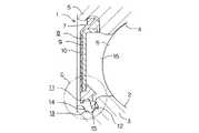
図1〜2は、本発明の実施の形態の1例を示している。尚、本発明の特徴は、密封板8cによるシール性を向上させるべく、この密封板8cを構成する弾性材10cの内周縁部を構成するシールリップ11cの形状を工夫した点にある。密封板付転がり軸受1bの基本構成自体は、前述の図5〜6に示した従来構造と同様であるから、同等部分に関する説明は省略若しくは簡略にし、以下、本発明の特徴部分並びに前述の従来構造と異なる部分を中心に説明する。
【0017】
本発明の密封板付転がり軸受1bを構成する上記密封板8cでは、上記シールリップ11cは、直径方向に関して外端部乃至中間部に、弾性変形部26を備える。この弾性変形部26は、軸方向に関する厚さ寸法よりも径方向に関する長さ寸法が、全長に亙って大きい。そして、上記弾性変形部26よりも直径方向内側である、上記シールリップ11cの端縁部12bの断面形状を、シール溝13を構成する1対の側壁面14、15のうち軸方向(図1の左右方向)内側の側壁面15側が断面円弧状の凸面である、略V字状としている。即ち、上記弾性材10cの端縁部12bは、上記側壁面15に対向する、直径方向外方に向かう程この側壁面15から離れる方向に傾斜した傾斜側面20と、この傾斜側面20よりも直径方向内方に位置して上記シール溝13の底面21に対向する、自由状態で円筒形の内周面22と、これら傾斜側面20と内周面22を連続させる、断面円弧形の曲面部23とを備える。
【0018】
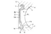
上述の様なシールリップ11cを備えた上記密封板8cの外周縁部を外輪5の係止溝7に係止した状態では、図2に鎖線で示す様に、上記シールリップ11cの弾性変形部26が内輪3の軸方向外方に弾性変形した状態で上記曲面部23が、上記シール溝13の側壁面15に摺接する。又、この様に曲面部23が側壁面15に摺接した状態で、上記側壁面15と上記傾斜側面20とのなす角度αが、30〜40度となる。又、上記シール溝13の底面21と上記内周面22とを、平行若しくは上記内輪3の軸方向外端面側(図1〜2の左側)に寄る程間隔が大きくなる方向に相対的に傾斜させている。そして、上記シール溝13の底面21と上記内周面22とのなす角度βを、0〜30度、更に好ましくは10〜20度としている。
【0019】
更に、上記シールリップ11cの端縁部12bと上記シール溝13の側壁面15との軸方向の締め代(弾性変形量)Lを、転動体6である玉の直径の1〜3%としている。そして、上記密封板8cの剛性に基づき上記締め代Lにより得られる、上記端縁部12bを上記側壁面15に押し付ける力をPとした場合に、P/Lが2.9〜9.8N/mm(300〜1000gf/mm)となる様に、前記弾性材10cの弾性及び形状を規制している。尚、上記シールリップ11cの内側には、上記内輪3の一部表面と近接対向してラビリンスシールを構成し、このシールリップ11c部分に達するグリースの量を抑える為のグリースリップ24を設けている。又、上記シールリップ11cの外側には、上記シール溝13よりも外側部分で上記内輪3の外周面に近接対向してラビリンスシールを構成し、上記シール溝13内に入り込む異物の量を抑える為のダストリップ25を設けている。
【0020】
上述の様に構成する本発明の密封板付転がり軸受1bの場合には、シール溝13の側壁面15とこの側壁面15に対向する傾斜側面20とのなす角度αを、30〜40度としている為、転動体6を保持した保持器からシール溝13側にグリースが押し出されても、くさび作用によるシールリップ11cの弾性変形が起きにくく、このシールリップ11cと上記側壁面15との間に微小隙間が生じにくい。上記角度αを30〜40度とする理由は、前述の通りである。
【0021】
又、上記シール溝13の底面21と上記内周面22とを平行若しくは上記内輪3の軸方向外端面側に寄る程間隔が大きくなる方向に相対的に、上記シール溝13の底面21とこの底面21に対向する内周面22とのなす角度βが0〜30度、更に好ましくは10〜20度となる様に傾斜させている為、外部から上記シール溝13内に入り込み、上記内周面22に接触した異物が、上記弾性材10cの端縁部12bを上記側壁面15から離れる方向に押す事はない。又、上記シール溝13内に入り込んだ異物には、上記内周面22との接触により、このシール溝13から出る方向の分力が加わる為、このシール溝13内に異物が溜りにくくなる。又、図示の例では、断面形状が円弧形である曲面部23を上記シール溝13の側壁面15に摺接させる為、安定した接触状態を保てる。更に、上記シールリップ11cの端縁部12bの締め代L及び押し付け力Pを規制する事により、上記シールリップ11cの弾性変形を更に起きにくくして、よりシール性を向上させている。尚、本発明の密封板付転がり軸受の保持器として、例えば特願平11−295823号に記載されている様な、グリースが内径側に留まるのを防ぐ構造を有する保持器を使用すれば、上記シール性をより有効に確保できる。
【0022】
【実施例】
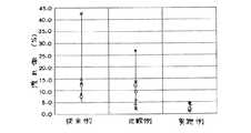
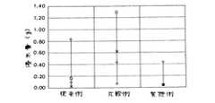
本発明の効果を確認する為、本発明者が行なった実験に就いて説明する。この実験は、図5〜6に示した密封板8を組み込んだ従来例と、図9に示す様に、本発明の場合とは逆に、シール溝13の底面21とシールリップ11eの内周面22aとを、内輪3の軸方向外端面側に寄る程間隔が小さくなる方向に相対的に傾斜させた密封板8eを組み込んだ比較例と、図1〜2に示した密封板8cを組み込んだ本発明品とを同一条件で使用した後、それぞれのグリースの漏れ率及び水の侵入量の測定を行なった。これら従来例、比較例及び本発明品の諸元を表1に、同じくグリースの漏れ率を測定した結果を図3に、同じく水の侵入量を測定した結果を図4に、それぞれ示した。尚、実験は、グリースの漏れ率に関しては同種の試料毎に8個ずつ、合計24個の試料を使用し、水の侵入量に関しては同種の試料毎に4個ずつ、合計12個の試料を使用して行なった。
【0024】
【表1】
この様な条件で行なった実験の結果を示す図3〜4から明らかな通り、本発明の密封板付転がり軸受によれは、グリースの漏れ及び異物の侵入を防止する作用を良好にして、耐久性の向上を図れる。
【0026】
【発明の効果】
本発明の密封板付転がり軸受は、以上に述べた通り構成され作用するので、グリースの漏洩及び異物の侵入を有効に防止し、密封板付転がり軸受を組み込んだ各種機器の信頼性並びに耐久性の向上に寄与できる。
【図面の簡単な説明】
【図1】 本発明の実施の形態の1例を示す部分断面図。
【図2】 図1のA部拡大図。
【図3】グリースの漏れに関して本発明の効果を確認する為に行なった実験の結果を示すグラフ。
【図4】水の侵入に関して本発明の効果を確認する為に行なった実験の結果を示すグラフ。
【図5】従来構造の第1例を示す部分断面図。
【図6】図5のC部拡大図。
【図7】従来構造の第2例を示す部分断面図。
【図8】従来構造の第3例を示す部分断面図。
【図9】本発明の効果を確認する為に使用した比較例を示す、図2と同様の図。
【符号の説明】
1、1a、1b 密封板付転がり軸受
2 内輪軌道
3 内輪
4 外輪軌道
5 外輪
6 転動体
7 係止溝
8、8a、8b、8c、8e 密封板
9 芯金
10、10a、10b、10c 弾性材
11、11a、11b、11c、11e シールリップ
12、12a、12b 端縁部
13 シール溝
14 側壁面
15 側壁面
16 空間
17 傾斜側面
18 傾斜側面
19 くびれ部
20 傾斜側面
21 底面
22、22a 内周面
23 曲面部
24 グリースリップ
25 ダストリップ
26 弾性変形部[0001]
[Industrial application fields]
The rolling bearing with a sealing plate according to the present invention relates to the improvement of the rolling bearing with a sealing plate incorporated in the rotation support portion of various mechanical devices, and is intended to improve the sealing performance by the sealing plate.
[0002]
[Prior art]
A rolling
[0003]
Each of these
[0004]
The rolling
[0005]
By the way, in the rolling bearing 1 with a sealing plate as described above, grease leakage may occur as follows. That is, when the
[0006]
In order to prevent grease leakage caused by such a cause, a sealing plate or the like is devised to improve the sealing performance. For example,FIG. 7 shows a rolling bearing 1a with a sealing plate described in JP-A-8-226449. The
[0007]
Further, asshown in FIG. 8 , the seal lip 11b constituting the inner peripheral edge of the
[0008]
[Problems to be solved by the invention]
In the case of the conventionally known
[0009]
In the case of the structure described in Japanese Patent Application Laid-Open No. 8-226449 shown inFIG. 7 , since the
[0010]
Further, in the case of the structure shown inFIG. 8 , the end portion of the
[0011]
Further, in the case of the structure described in Japanese Patent Laid-Open Nos. 7-293571 and 7-139553, an air hole for releasing the pressure in the internal space in order to bring the seal lip into sliding contact with the side wall surface on the outer side in the axial direction. It is necessary to provide grease, and grease easily leaks from this air hole. Furthermore, in the case of the structure described in Japanese Utility Model Publication No. 6-27859, the seal lip constituting the labyrinth gap is easily hardened due to thermal deterioration or the like, and the grease lip can be sufficiently secured over a long period of time. It is difficult to maintain good sealability over a long period of time.
The rolling bearing with a sealing plate of the present invention is invented to eliminate any of the above disadvantages.
[0012]
[Means for Solving the Problems]
The rolling bearing with a sealing plate of the present invention, like the conventional rolling bearing with a sealing plate, includes an inner ring having an inner ring raceway on an outer peripheral surface, an outer ring having an outer ring raceway on an inner peripheral surface, and the inner ring raceway and the outer ring raceway. A plurality of rolling elements provided between the outer ring and an outer peripheral edge formed on the inner peripheral surface of the end of the outer ring. And a sealing plate locked to the stop groove over the entire circumference. Andthe tip edge of the seal lip provided on the end edge of the elastic material constituting the inner peripheral edge of the sealing plateis closer to the inner ring track in the seal groove formed on the outer peripheral surface of the end of theinner ring. It is in sliding contact with theinner side wall surface.
In particular, in the rolling bearing with a sealing plate according to the present invention, theseal lip includes an elastically deforming portion whose length in the radial direction is larger than the thickness in the axial direction over the entire length. diametrically inward of the section, an inclined side surface facing the side wall surface of the seal groove, an inner peripheral surface opposed to the bottom surface of the seal groove located diametrically inwardly than the inclined side surface, the inclined side surface it is continuous and the inner peripheral surface andis provided with a a continuous portion. Then, the continuous portion is slidably brought into contact with the side wall surface of the seal groove, and the angle formed between the side wall surface and the inclined side surface is30 to40 degrees in a state where the continuous portion is in contact with the side wall surface. The angle formed by the bottom surface and the inner peripheral surface is inclined relative to a direction in which the bottom surface of the seal groove and the inner peripheral surface are parallel or the distance between the inner ring is increased toward the outer end surface in the axial direction of the inner ring. Is set to 0 to 30 degrees (preferably 10 to 20 degrees).
Preferably, the continuous portion is a curved surface portion having a circular cross section. In addition, the axial interference between the edge portion of the elastic material and the side wall surface of the seal groove is L, and the force for pressing the end edge portion to the side wall surface based on the rigidity of the sealing plate is P. In this case, P / L is set to 2.9 to 9.8 N / mm (300 to 1000 gf / mm), and the fastening allowance L is set to 1 to 3% of the diameter of the ball as the rolling element.
[0013]
[Action]
In the case of the rolling bearing with a sealing plate of the present invention configured as described above, theangle formed by the side wall surface of the seal groove and the inclined side surface facing this side wall surface is restricted to30 to 40 degrees. Even if the grease is pushed out to the groove side, elastic deformation of the elastic material due to the wedge action hardly occurs, and a minute gap is hardly generated between the elastic material and the side wall surface. When the angle isless than 30 degrees , the minute gap is likely to occur due to a wedge action that occurs when grease is pushed out to the seal groove side. When the angle exceeds40 degrees , the rigidity of the portion where the inclined side surface is formed at the edge of the elastic material is lowered. In other words, when the grease is pushed out to the seal groove side, the force by which the inclined side surface is pushed by the grease is increased, and the minute gap is easily generated. Therefore, the angle isregulated to a range of30 to40 degrees.
[0014]
Further, the bottom surface of the seal groove and the inner circumference facing the bottom surface are relatively parallel to each other or in a direction in which the distance increases as the distance from the inner ring surface toward the outer end surface in the axial direction of the inner ring increases. Since the angle with the surface is 0 to 30 degrees, more preferably 10 to 20 degrees, the foreign material that enters the seal groove from the outside and contacts the inner peripheral surface is the elastic material. The edge part of this is not pushed away from the side wall surface. If the inclination direction is reversed, the edge of the elastic material tends to move away from the side wall surface due to the foreign matter that has entered the seal groove, and the sealing performance may be reduced. Even if the inclination direction is as described above, when the angle formed between the bottom surface of the seal groove and the inner peripheral surface facing the bottom surface exceeds 30 degrees, the edge of the elastic material The thickness of the portion that comes into sliding contact with the side wall surface is reduced, and the rigidity of this portion is reduced, making it difficult to ensure the surface pressure of the sliding contact portion between the end edge portion and the side wall surface, and it is also difficult to ensure sufficient sealing performance. Become. Therefore, the inclination direction and the inclination angle between the bottom surface and the inner peripheral surface of the seal groove are regulated as described above. If the inclination angle is in the range of 10 to 20 degrees, the sealing performance can be more effectively ensured.
[0015]
In addition, if the continuous part which makes an inclined side surface and an internal peripheral surface continue is a curved-surface part with a circular arc cross section, the slidable contact state between the continuous part and the side wall surface of the seal groove can be stabilized, and the better Ensuring sealing performance.
Furthermore, when the axial interference between the end edge of the elastic material and the side wall surface of the seal groove is L, and the force pressing the end edge against the side wall surface based on the rigidity of the sealing plate is P Further, if P / L is 2.9 to 9.8 N / mm (300 to 1000 gf / mm) and the above-mentioned interference L is 1 to 3% of the diameter of the ball as the rolling element, the sealing performance is lowered. It is possible to further prevent the elastic deformation of the elastic material to be caused and to further secure the sealing performance. When the P / L is less than 2.9 N / mm and the tightening allowance L is less than 1%, the contact pressure at the sliding contact portion between the continuous portion and the side wall surface is too low, and sufficient sealing performance is obtained. It becomes difficult. In addition, when the P / L is less than 2.9 N / mm and the tightening allowance L exceeds 3%, the rigidity of the sealing plate is too low, and the fluctuation of the outer peripheral edge of the sealing plate becomes large and stable. It becomes difficult to obtain a sealing property. On the contrary, if the P / L exceeds 9.8 N / mm and the tightening allowance L is less than 1%, the rigidity of the sealing plate is too high, and the fluctuation of the contact pressure becomes large even with a slight displacement. After all, it becomes difficult to obtain a stable sealing property. In addition, when the P / L exceeds 9.8 N / mm and the tightening allowance L exceeds 3%, the contact pressure of the sliding contact portion becomes excessive and the rotational torque of the rolling bearing with a sealing plate is increased. Since it becomes large, the continuous part is worn out, and it becomes impossible to secure a sealing property for a long time.
[0016]
DETAILED DESCRIPTION OF THE INVENTION
1 and 2 show anexample ofan embodiment of the present invention. The feature of the present invention is that the shape of the
[0017]
In the sealing
[0018]
In a state where the outer peripheral edge of the sealing
[0019]
Furthermore, the axial tightening margin (elastic deformation amount) L between the
[0020]
In the case of the rolling bearing 1b with the sealing plate of the present invention configured as described above, theangle α formed between the
[0021]
In addition, the
[0022]
【Example】
In order to confirm the effect of the present invention, an experiment conducted by the present inventor will be described. In this experiment, asshown inFIG. 9 , the
[0024]
[Table 1]
As is apparent fromFIGS. 3 to4 showing the results of the experiment conducted under such conditions, the rolling bearing with a sealing plate according to the present invention has a good effect of preventing leakage of grease and intrusion of foreign matter, and durability. Can be improved.
[0026]
【The invention's effect】
Since the rolling bearing with a sealing plate of the present invention is configured and operates as described above, it effectively prevents leakage of grease and intrusion of foreign matter, and improves the reliability and durability of various devices incorporating the rolling bearing with a sealing plate. Can contribute.
[Brief description of the drawings]
FIG. 1 is a partial cross-sectional view showing anexample of anembodiment of the present invention.
FIG. 2 is an enlarged view of a portion A in FIG.
FIG. 3is a graph showing the results of an experiment performed to confirm the effect of the present invention with respect to grease leakage.
FIG. 4is a graph showing the results of an experiment conducted to confirm the effect of the present invention with respect to water intrusion.
FIG. 5is a partial sectional view showing a first example of a conventional structure.
6 is anenlarged view of a portion C in FIG.
FIG. 7is a partial sectional view showing a second example of a conventional structure.
FIG. 8is a partial sectional view showing a third example of a conventional structure.
FIG. 9is a view similar to FIG. 2, showing a comparative example used to confirm the effect of the present invention.
[Explanation of symbols]
DESCRIPTION OF
25 Dustrip
26 Elastic deformation part
Claims (3)
Translated fromJapanesePriority Applications (4)
| Application Number | Priority Date | Filing Date | Title |
|---|---|---|---|
| JP32530199AJP4465755B2 (en) | 1999-11-16 | 1999-11-16 | Rolling bearing with sealing plate |
| US09/691,457US6719459B1 (en) | 1999-10-18 | 2000-10-18 | Ball bearing |
| US10/747,669US7404675B2 (en) | 1999-10-18 | 2003-12-29 | Ball bearing |
| US10/747,730US7070334B2 (en) | 1999-10-18 | 2003-12-29 | Ball Bearing |
Applications Claiming Priority (1)
| Application Number | Priority Date | Filing Date | Title |
|---|---|---|---|
| JP32530199AJP4465755B2 (en) | 1999-11-16 | 1999-11-16 | Rolling bearing with sealing plate |
Publications (3)
| Publication Number | Publication Date |
|---|---|
| JP2001140907A JP2001140907A (en) | 2001-05-22 |
| JP2001140907A5 JP2001140907A5 (en) | 2006-12-28 |
| JP4465755B2true JP4465755B2 (en) | 2010-05-19 |
Family
ID=18175297
Family Applications (1)
| Application Number | Title | Priority Date | Filing Date |
|---|---|---|---|
| JP32530199AExpired - LifetimeJP4465755B2 (en) | 1999-10-18 | 1999-11-16 | Rolling bearing with sealing plate |
Country Status (1)
| Country | Link |
|---|---|
| JP (1) | JP4465755B2 (en) |
Families Citing this family (8)
| Publication number | Priority date | Publication date | Assignee | Title |
|---|---|---|---|---|
| JP2005163900A (en)* | 2003-12-02 | 2005-06-23 | Koyo Seiko Co Ltd | Rolling bearing |
| EP1698790B1 (en) | 2005-03-01 | 2011-12-28 | NTN Corporation | Sealed rolling bearing |
| JP4601555B2 (en)* | 2005-07-21 | 2010-12-22 | Ntn株式会社 | Sealed rolling bearing |
| JP2012197940A (en)* | 2006-03-27 | 2012-10-18 | Ntn Corp | Rolling bearing |
| JP2010138931A (en) | 2008-12-09 | 2010-06-24 | Ntn Corp | Sealed rolling bearing |
| JP6331754B2 (en) | 2013-07-09 | 2018-05-30 | 日本精工株式会社 | Ball bearing with seal ring |
| JP6501823B2 (en) | 2017-05-23 | 2019-04-17 | Ntn株式会社 | Bearing seal structure, pulley bearing, and method of designing bearing seal |
| KR102604188B1 (en)* | 2019-04-03 | 2023-11-23 | 주식회사 베어링아트 | Rolling bearing having improved sealing function |
- 1999
- 1999-11-16JPJP32530199Apatent/JP4465755B2/ennot_activeExpired - Lifetime
Also Published As
| Publication number | Publication date |
|---|---|
| JP2001140907A (en) | 2001-05-22 |
Similar Documents
| Publication | Publication Date | Title |
|---|---|---|
| EP0371075B1 (en) | Oil seal with antirotation ribs | |
| US4558962A (en) | Snap ring | |
| JP5920443B2 (en) | Rolling bearing with seal ring | |
| GB2112879A (en) | Self - venting seals | |
| CN205677987U (en) | Band sealing ring ball bearing | |
| US20100066030A1 (en) | Hermetic sealing device | |
| JPH10252762A (en) | Sealing device for rolling bearings | |
| JP2519507B2 (en) | Steering wheel bearing | |
| US8641289B2 (en) | Triple-lip seals for bearings and bearings incorporating the same | |
| US6817769B2 (en) | Roller bearing having high performance bearing seal and cartridge | |
| CN102439324A (en) | Bearing seal assembly, particularly for agricultural applications | |
| EP1875093B1 (en) | A sealed bearing | |
| JP4465755B2 (en) | Rolling bearing with sealing plate | |
| JP6755156B2 (en) | Rolling bearing with seal for pulley unit | |
| JPH0680954U (en) | Sealing device | |
| JP2002206550A (en) | Sealing device for rolling bearings | |
| JPH0429130Y2 (en) | ||
| CN109661523B (en) | Axle bearing device | |
| CN106122263A (en) | Bearing including resilient bearing flange | |
| JP2602196B2 (en) | Bearing with seal | |
| KR20230040373A (en) | A seal arrangement for a wheel bearing, and a wheel bearing unit including the seal arrangement | |
| JPH0324892Y2 (en) | ||
| JP4506262B2 (en) | Sealing means for rolling bearing unit Rolling bearing unit | |
| JPH08159164A (en) | Rolling bearing with seal | |
| JPH083710Y2 (en) | Self-aligning seal structure for ball bearings with tilt function |
Legal Events
| Date | Code | Title | Description |
|---|---|---|---|
| A521 | Written amendment | Free format text:JAPANESE INTERMEDIATE CODE: A523 Effective date:20061109 | |
| A621 | Written request for application examination | Free format text:JAPANESE INTERMEDIATE CODE: A621 Effective date:20061109 | |
| A977 | Report on retrieval | Free format text:JAPANESE INTERMEDIATE CODE: A971007 Effective date:20090709 | |
| A131 | Notification of reasons for refusal | Free format text:JAPANESE INTERMEDIATE CODE: A131 Effective date:20090804 | |
| A521 | Written amendment | Free format text:JAPANESE INTERMEDIATE CODE: A523 Effective date:20091005 | |
| TRDD | Decision of grant or rejection written | ||
| A01 | Written decision to grant a patent or to grant a registration (utility model) | Free format text:JAPANESE INTERMEDIATE CODE: A01 Effective date:20100202 | |
| A01 | Written decision to grant a patent or to grant a registration (utility model) | Free format text:JAPANESE INTERMEDIATE CODE: A01 | |
| A61 | First payment of annual fees (during grant procedure) | Free format text:JAPANESE INTERMEDIATE CODE: A61 Effective date:20100215 | |
| R150 | Certificate of patent or registration of utility model | Ref document number:4465755 Country of ref document:JP Free format text:JAPANESE INTERMEDIATE CODE: R150 Free format text:JAPANESE INTERMEDIATE CODE: R150 | |
| FPAY | Renewal fee payment (event date is renewal date of database) | Free format text:PAYMENT UNTIL: 20130305 Year of fee payment:3 | |
| FPAY | Renewal fee payment (event date is renewal date of database) | Free format text:PAYMENT UNTIL: 20130305 Year of fee payment:3 | |
| FPAY | Renewal fee payment (event date is renewal date of database) | Free format text:PAYMENT UNTIL: 20140305 Year of fee payment:4 | |
| R250 | Receipt of annual fees | Free format text:JAPANESE INTERMEDIATE CODE: R250 | |
| EXPY | Cancellation because of completion of term |