JP4464282B2 - Curable medium for implantable medical devices - Google Patents
Curable medium for implantable medical devicesDownload PDFInfo
- Publication number
- JP4464282B2 JP4464282B2JP2004563576AJP2004563576AJP4464282B2JP 4464282 B2JP4464282 B2JP 4464282B2JP 2004563576 AJP2004563576 AJP 2004563576AJP 2004563576 AJP2004563576 AJP 2004563576AJP 4464282 B2JP4464282 B2JP 4464282B2
- Authority
- JP
- Japan
- Prior art keywords
- curable medium
- orthopedic
- balloon
- treatment site
- bone
- Prior art date
- Legal status (The legal status is an assumption and is not a legal conclusion. Google has not performed a legal analysis and makes no representation as to the accuracy of the status listed.)
- Expired - Fee Related
Links
- 210000000988bone and boneAnatomy0.000claimsdescription119
- 230000000399orthopedic effectEffects0.000claimsdescription49
- 229920005989resinPolymers0.000claimsdescription33
- 239000011347resinSubstances0.000claimsdescription33
- IISBACLAFKSPIT-UHFFFAOYSA-Nbisphenol AChemical compoundC=1C=C(O)C=CC=1C(C)(C)C1=CC=C(O)C=C1IISBACLAFKSPIT-UHFFFAOYSA-N0.000claimsdescription26
- GYZLOYUZLJXAJU-UHFFFAOYSA-Ndiglycidyl etherChemical compoundC1OC1COCC1CO1GYZLOYUZLJXAJU-UHFFFAOYSA-N0.000claimsdescription26
- 238000011282treatmentMethods0.000claimsdescription23
- 239000004593EpoxySubstances0.000claimsdescription22
- 125000001931aliphatic groupChemical group0.000claimsdescription19
- 239000000203mixtureSubstances0.000claimsdescription18
- 230000003068static effectEffects0.000claimsdescription16
- 125000003118aryl groupChemical group0.000claimsdescription15
- 239000003795chemical substances by applicationSubstances0.000claimsdescription14
- XFNJVJPLKCPIBV-UHFFFAOYSA-NtrimethylenediamineChemical compoundNCCCNXFNJVJPLKCPIBV-UHFFFAOYSA-N0.000claimsdescription12
- 125000005265dialkylamine groupChemical group0.000claimsdescription11
- PXKLMJQFEQBVLD-UHFFFAOYSA-Nbisphenol FChemical compoundC1=CC(O)=CC=C1CC1=CC=C(O)C=C1PXKLMJQFEQBVLD-UHFFFAOYSA-N0.000claimsdescription10
- IMUDHTPIFIBORV-UHFFFAOYSA-NaminoethylpiperazineChemical compoundNCCN1CCNCC1IMUDHTPIFIBORV-UHFFFAOYSA-N0.000claimsdescription9
- 150000001412aminesChemical class0.000claimsdescription7
- 238000007906compressionMethods0.000claimsdescription7
- 230000006835compressionEffects0.000claimsdescription7
- 238000012999compression bendingMethods0.000claimsdescription7
- 229920000647polyepoxidePolymers0.000claimsdescription7
- 125000000217alkyl groupChemical group0.000claimsdescription5
- 239000003822epoxy resinSubstances0.000claimsdescription5
- 230000001737promoting effectEffects0.000claimsdescription2
- 238000004873anchoringMethods0.000claims4
- CDQSJQSWAWPGKG-UHFFFAOYSA-Nbutane-1,1-diolChemical compoundCCCC(O)OCDQSJQSWAWPGKG-UHFFFAOYSA-N0.000claims3
- 239000000306componentSubstances0.000claims1
- 239000012533medium componentSubstances0.000claims1
- 238000000034methodMethods0.000description82
- 238000010438heat treatmentMethods0.000description64
- 239000000463materialSubstances0.000description43
- 238000002347injectionMethods0.000description25
- 239000007924injectionSubstances0.000description25
- 229920000049Carbon (fiber)Polymers0.000description24
- 239000004917carbon fiberSubstances0.000description24
- 239000007943implantSubstances0.000description24
- 239000000835fiberSubstances0.000description19
- 230000003014reinforcing effectEffects0.000description19
- 238000002513implantationMethods0.000description15
- VNWKTOKETHGBQD-UHFFFAOYSA-NmethaneChemical compoundCVNWKTOKETHGBQD-UHFFFAOYSA-N0.000description15
- 230000036961partial effectEffects0.000description14
- 150000001875compoundsChemical class0.000description12
- 239000010410layerSubstances0.000description12
- 238000001802infusionMethods0.000description11
- 210000001519tissueAnatomy0.000description11
- 229920000642polymerPolymers0.000description10
- 229910052751metalInorganic materials0.000description9
- 239000002184metalSubstances0.000description9
- 238000011065in-situ storageMethods0.000description8
- 239000003550markerSubstances0.000description8
- 230000002787reinforcementEffects0.000description8
- 239000004677NylonSubstances0.000description7
- 239000002131composite materialSubstances0.000description7
- 238000009472formulationMethods0.000description7
- 229920001778nylonPolymers0.000description7
- -1polyethylenePolymers0.000description7
- 238000006116polymerization reactionMethods0.000description7
- 229920002635polyurethanePolymers0.000description7
- 239000004814polyurethaneSubstances0.000description7
- 230000008569processEffects0.000description7
- ISWSIDIOOBJBQZ-UHFFFAOYSA-NPhenolChemical compoundOC1=CC=CC=C1ISWSIDIOOBJBQZ-UHFFFAOYSA-N0.000description6
- 238000002399angioplastyMethods0.000description6
- 230000000694effectsEffects0.000description6
- 238000002594fluoroscopyMethods0.000description6
- 230000006870functionEffects0.000description6
- 230000004927fusionEffects0.000description6
- 238000003780insertionMethods0.000description6
- 230000037431insertionEffects0.000description6
- 239000007788liquidSubstances0.000description6
- 238000002156mixingMethods0.000description6
- 239000004698PolyethyleneSubstances0.000description5
- RTAQQCXQSZGOHL-UHFFFAOYSA-NTitaniumChemical compound[Ti]RTAQQCXQSZGOHL-UHFFFAOYSA-N0.000description5
- SJIXIEVUJKKYKS-UHFFFAOYSA-Nbutane-1,1-diol;2-(oxiran-2-ylmethoxymethyl)oxiraneChemical compoundCCCC(O)O.C1OC1COCC1CO1SJIXIEVUJKKYKS-UHFFFAOYSA-N0.000description5
- 125000001400nonyl groupChemical group[H]C([*])([H])C([H])([H])C([H])([H])C([H])([H])C([H])([H])C([H])([H])C([H])([H])C([H])([H])C([H])([H])[H]0.000description5
- 230000000704physical effectEffects0.000description5
- 239000005020polyethylene terephthalateSubstances0.000description5
- 238000001356surgical procedureMethods0.000description5
- 239000010936titaniumSubstances0.000description5
- OKTJSMMVPCPJKN-UHFFFAOYSA-NCarbonChemical compound[C]OKTJSMMVPCPJKN-UHFFFAOYSA-N0.000description4
- 206010061246Intervertebral disc degenerationDiseases0.000description4
- 238000004891communicationMethods0.000description4
- 230000000295complement effectEffects0.000description4
- 238000013461designMethods0.000description4
- 201000010099diseaseDiseases0.000description4
- 208000037265diseases, disorders, signs and symptomsDiseases0.000description4
- 150000002118epoxidesChemical group0.000description4
- 230000005284excitationEffects0.000description4
- 208000014674injuryDiseases0.000description4
- BASFCYQUMIYNBI-UHFFFAOYSA-NplatinumChemical compound[Pt]BASFCYQUMIYNBI-UHFFFAOYSA-N0.000description4
- 229920000573polyethylenePolymers0.000description4
- 229920000139polyethylene terephthalatePolymers0.000description4
- 229920001343polytetrafluoroethylenePolymers0.000description4
- 239000004810polytetrafluoroethyleneSubstances0.000description4
- 238000000926separation methodMethods0.000description4
- 229910052719titaniumInorganic materials0.000description4
- VILCJCGEZXAXTO-UHFFFAOYSA-N2,2,2-tetramineChemical compoundNCCNCCNCCNVILCJCGEZXAXTO-UHFFFAOYSA-N0.000description3
- 208000003618Intervertebral Disc DisplacementDiseases0.000description3
- OFBQJSOFQDEBGM-UHFFFAOYSA-NPentaneChemical groupCCCCCOFBQJSOFQDEBGM-UHFFFAOYSA-N0.000description3
- 208000027418Wounds and injuryDiseases0.000description3
- 230000008901benefitEffects0.000description3
- 238000001574biopsyMethods0.000description3
- 229910052799carbonInorganic materials0.000description3
- 239000003054catalystSubstances0.000description3
- 239000011248coating agentSubstances0.000description3
- 238000000576coating methodMethods0.000description3
- 238000004132cross linkingMethods0.000description3
- 230000006378damageEffects0.000description3
- 238000006073displacement reactionMethods0.000description3
- 239000004744fabricSubstances0.000description3
- 239000012530fluidSubstances0.000description3
- 230000007246mechanismEffects0.000description3
- 230000017074necrotic cell deathEffects0.000description3
- 229910001000nickel titaniumInorganic materials0.000description3
- 229920003229poly(methyl methacrylate)Polymers0.000description3
- 239000004926polymethyl methacrylateSubstances0.000description3
- 230000002980postoperative effectEffects0.000description3
- 230000002829reductive effectEffects0.000description3
- 238000007789sealingMethods0.000description3
- 239000013464silicone adhesiveSubstances0.000description3
- 239000002356single layerSubstances0.000description3
- 239000007787solidSubstances0.000description3
- 230000000087stabilizing effectEffects0.000description3
- 229910001220stainless steelInorganic materials0.000description3
- 239000010935stainless steelSubstances0.000description3
- GUVRBAGPIYLISA-UHFFFAOYSA-Ntantalum atomChemical compound[Ta]GUVRBAGPIYLISA-UHFFFAOYSA-N0.000description3
- 238000012800visualizationMethods0.000description3
- RPNUMPOLZDHAAY-UHFFFAOYSA-NDiethylenetriamineChemical compoundNCCNCCNRPNUMPOLZDHAAY-UHFFFAOYSA-N0.000description2
- 229920000271Kevlar®Polymers0.000description2
- GLUUGHFHXGJENI-UHFFFAOYSA-NPiperazineChemical compoundC1CNCCN1GLUUGHFHXGJENI-UHFFFAOYSA-N0.000description2
- 239000004696Poly ether ether ketoneSubstances0.000description2
- ATUOYWHBWRKTHZ-UHFFFAOYSA-NPropaneChemical compoundCCCATUOYWHBWRKTHZ-UHFFFAOYSA-N0.000description2
- 206010041591Spinal osteoarthritisDiseases0.000description2
- 208000007103SpondylolisthesisDiseases0.000description2
- 230000009471actionEffects0.000description2
- 239000000853adhesiveSubstances0.000description2
- 230000001070adhesive effectEffects0.000description2
- 230000004323axial lengthEffects0.000description2
- JUPQTSLXMOCDHR-UHFFFAOYSA-Nbenzene-1,4-diol;bis(4-fluorophenyl)methanoneChemical compoundOC1=CC=C(O)C=C1.C1=CC(F)=CC=C1C(=O)C1=CC=C(F)C=C1JUPQTSLXMOCDHR-UHFFFAOYSA-N0.000description2
- 229920000249biocompatible polymerPolymers0.000description2
- 230000036760body temperatureEffects0.000description2
- 239000007767bonding agentSubstances0.000description2
- 210000002805bone matrixAnatomy0.000description2
- 239000004020conductorSubstances0.000description2
- 238000010586diagramMethods0.000description2
- 239000003814drugSubstances0.000description2
- 229940079593drugDrugs0.000description2
- 230000004064dysfunctionEffects0.000description2
- 238000005516engineering processMethods0.000description2
- 125000003700epoxy groupChemical group0.000description2
- 238000001125extrusionMethods0.000description2
- 238000011049fillingMethods0.000description2
- 230000009969flowable effectEffects0.000description2
- PCHJSUWPFVWCPO-UHFFFAOYSA-NgoldChemical compound[Au]PCHJSUWPFVWCPO-UHFFFAOYSA-N0.000description2
- 239000010931goldSubstances0.000description2
- 229910052737goldInorganic materials0.000description2
- 229910052588hydroxylapatiteInorganic materials0.000description2
- 239000004761kevlarSubstances0.000description2
- 210000003041ligamentAnatomy0.000description2
- 238000004519manufacturing processMethods0.000description2
- 239000011159matrix materialSubstances0.000description2
- 238000000465mouldingMethods0.000description2
- ORQBXQOJMQIAOY-UHFFFAOYSA-NnobeliumChemical compound[No]ORQBXQOJMQIAOY-UHFFFAOYSA-N0.000description2
- 230000037361pathwayEffects0.000description2
- XYJRXVWERLGGKC-UHFFFAOYSA-Dpentacalcium;hydroxide;triphosphateChemical compound[OH-].[Ca+2].[Ca+2].[Ca+2].[Ca+2].[Ca+2].[O-]P([O-])([O-])=O.[O-]P([O-])([O-])=O.[O-]P([O-])([O-])=OXYJRXVWERLGGKC-UHFFFAOYSA-D0.000description2
- 230000002093peripheral effectEffects0.000description2
- 229910052697platinumInorganic materials0.000description2
- 239000004417polycarbonateSubstances0.000description2
- 229920002530polyetherether ketonePolymers0.000description2
- 230000000379polymerizing effectEffects0.000description2
- 229920001296polysiloxanePolymers0.000description2
- 239000000047productSubstances0.000description2
- 125000006850spacer groupChemical group0.000description2
- 208000005198spinal stenosisDiseases0.000description2
- 208000005801spondylosisDiseases0.000description2
- 229910052715tantalumInorganic materials0.000description2
- 230000008733traumaEffects0.000description2
- WFKWXMTUELFFGS-UHFFFAOYSA-NtungstenChemical compound[W]WFKWXMTUELFFGS-UHFFFAOYSA-N0.000description2
- 229920004934Dacron®Polymers0.000description1
- 229910001200FerrotitaniumInorganic materials0.000description1
- 206010019909HerniaDiseases0.000description1
- 241001465754MetazoaSpecies0.000description1
- LSDPWZHWYPCBBB-UHFFFAOYSA-NMethanethiolChemical compoundSCLSDPWZHWYPCBBB-UHFFFAOYSA-N0.000description1
- 208000006735PeriostitisDiseases0.000description1
- 229920002614Polyether block amidePolymers0.000description1
- FAPWRFPIFSIZLT-UHFFFAOYSA-MSodium chlorideChemical compound[Na+].[Cl-]FAPWRFPIFSIZLT-UHFFFAOYSA-M0.000description1
- 241000282887SuidaeSpecies0.000description1
- 208000002847Surgical WoundDiseases0.000description1
- 206010052428WoundDiseases0.000description1
- 229920000122acrylonitrile butadiene styrenePolymers0.000description1
- 239000004676acrylonitrile butadiene styreneSubstances0.000description1
- 230000004913activationEffects0.000description1
- 125000002723alicyclic groupChemical group0.000description1
- 150000001335aliphatic alkanesChemical group0.000description1
- 150000003973alkyl aminesChemical class0.000description1
- 125000003277amino groupChemical group0.000description1
- 230000033115angiogenesisEffects0.000description1
- 210000001367arteryAnatomy0.000description1
- 230000000712assemblyEffects0.000description1
- 238000000429assemblyMethods0.000description1
- 230000004888barrier functionEffects0.000description1
- 238000005452bendingMethods0.000description1
- 230000002146bilateral effectEffects0.000description1
- 210000000013bile ductAnatomy0.000description1
- 239000000560biocompatible materialSubstances0.000description1
- 238000007470bone biopsyMethods0.000description1
- 239000001273butaneSubstances0.000description1
- 239000006227byproductSubstances0.000description1
- 125000004432carbon atomChemical groupC*0.000description1
- 230000000747cardiac effectEffects0.000description1
- 210000000748cardiovascular systemAnatomy0.000description1
- 230000008859changeEffects0.000description1
- 238000006243chemical reactionMethods0.000description1
- 238000005345coagulationMethods0.000description1
- 230000015271coagulationEffects0.000description1
- 238000010276constructionMethods0.000description1
- 238000007796conventional methodMethods0.000description1
- 239000002826coolantSubstances0.000description1
- 239000012809cooling fluidSubstances0.000description1
- 230000009849deactivationEffects0.000description1
- 230000007547defectEffects0.000description1
- 230000002950deficientEffects0.000description1
- 238000007872degassingMethods0.000description1
- 150000004985diaminesChemical class0.000description1
- 230000010339dilationEffects0.000description1
- 239000003085diluting agentSubstances0.000description1
- 230000009977dual effectEffects0.000description1
- 239000012777electrically insulating materialSubstances0.000description1
- 229910000701elgiloys (Co-Cr-Ni Alloy)Inorganic materials0.000description1
- 150000003947ethylaminesChemical class0.000description1
- 238000001704evaporationMethods0.000description1
- 229920000295expanded polytetrafluoroethylenePolymers0.000description1
- 210000003195fasciaAnatomy0.000description1
- 238000005429filling processMethods0.000description1
- 239000003205fragranceSubstances0.000description1
- 238000007499fusion processingMethods0.000description1
- 210000001035gastrointestinal tractAnatomy0.000description1
- 229910002804graphiteInorganic materials0.000description1
- 239000010439graphiteSubstances0.000description1
- KHYBPSFKEHXSLX-UHFFFAOYSA-NiminotitaniumChemical compound[Ti]=NKHYBPSFKEHXSLX-UHFFFAOYSA-N0.000description1
- 238000010952in-situ formationMethods0.000description1
- 238000001746injection mouldingMethods0.000description1
- 238000009413insulationMethods0.000description1
- 238000002684laminectomyMethods0.000description1
- 238000003698laser cuttingMethods0.000description1
- 229920000126latexPolymers0.000description1
- 239000004816latexSubstances0.000description1
- 238000011068loading methodMethods0.000description1
- 230000007774longtermEffects0.000description1
- 230000013011matingEffects0.000description1
- 150000003956methylaminesChemical class0.000description1
- 238000012986modificationMethods0.000description1
- 230000004048modificationEffects0.000description1
- 239000003607modifierSubstances0.000description1
- 239000000178monomerSubstances0.000description1
- 210000003205muscleAnatomy0.000description1
- IJDNQMDRQITEOD-UHFFFAOYSA-Nn-butaneChemical compoundCCCCIJDNQMDRQITEOD-UHFFFAOYSA-N0.000description1
- HLXZNVUGXRDIFK-UHFFFAOYSA-Nnickel titaniumChemical compound[Ti].[Ti].[Ti].[Ti].[Ti].[Ti].[Ti].[Ti].[Ti].[Ti].[Ti].[Ni].[Ni].[Ni].[Ni].[Ni].[Ni].[Ni].[Ni].[Ni].[Ni].[Ni].[Ni].[Ni].[Ni]HLXZNVUGXRDIFK-UHFFFAOYSA-N0.000description1
- 239000000615nonconductorSubstances0.000description1
- 239000013307optical fiberSubstances0.000description1
- 210000000056organAnatomy0.000description1
- 238000013021overheatingMethods0.000description1
- 230000000149penetrating effectEffects0.000description1
- 210000003460periosteumAnatomy0.000description1
- 230000036314physical performanceEffects0.000description1
- IYPZRUYMFDWKSS-UHFFFAOYSA-Npiperazin-1-amineChemical classNN1CCNCC1IYPZRUYMFDWKSS-UHFFFAOYSA-N0.000description1
- 229920003023plasticPolymers0.000description1
- 239000004033plasticSubstances0.000description1
- 229920001084poly(chloroprene)Polymers0.000description1
- 229920000515polycarbonatePolymers0.000description1
- 239000011148porous materialSubstances0.000description1
- 239000000843powderSubstances0.000description1
- 239000002243precursorSubstances0.000description1
- 239000001294propaneSubstances0.000description1
- 125000006308propyl amino groupChemical class0.000description1
- 230000009467reductionEffects0.000description1
- 239000012783reinforcing fiberSubstances0.000description1
- 230000000452restraining effectEffects0.000description1
- 230000000717retained effectEffects0.000description1
- 238000005096rolling processMethods0.000description1
- 239000004065semiconductorSubstances0.000description1
- 239000011780sodium chlorideSubstances0.000description1
- 239000007779soft materialSubstances0.000description1
- 238000007711solidificationMethods0.000description1
- 230000008023solidificationEffects0.000description1
- 239000002904solventSubstances0.000description1
- 238000000935solvent evaporationMethods0.000description1
- 230000006641stabilisationEffects0.000description1
- 238000011105stabilizationMethods0.000description1
- 238000011272standard treatmentMethods0.000description1
- 239000000126substanceSubstances0.000description1
- 239000000758substrateSubstances0.000description1
- 210000002435tendonAnatomy0.000description1
- 238000012360testing methodMethods0.000description1
- 230000003685thermal hair damageEffects0.000description1
- 238000002604ultrasonographyMethods0.000description1
- XLYOFNOQVPJJNP-UHFFFAOYSA-NwaterSubstancesOXLYOFNOQVPJJNP-UHFFFAOYSA-N0.000description1
- 238000009736wettingMethods0.000description1
Images


Classifications
- A—HUMAN NECESSITIES
- A61—MEDICAL OR VETERINARY SCIENCE; HYGIENE
- A61L—METHODS OR APPARATUS FOR STERILISING MATERIALS OR OBJECTS IN GENERAL; DISINFECTION, STERILISATION OR DEODORISATION OF AIR; CHEMICAL ASPECTS OF BANDAGES, DRESSINGS, ABSORBENT PADS OR SURGICAL ARTICLES; MATERIALS FOR BANDAGES, DRESSINGS, ABSORBENT PADS OR SURGICAL ARTICLES
- A61L27/00—Materials for grafts or prostheses or for coating grafts or prostheses
- A—HUMAN NECESSITIES
- A61—MEDICAL OR VETERINARY SCIENCE; HYGIENE
- A61B—DIAGNOSIS; SURGERY; IDENTIFICATION
- A61B17/00—Surgical instruments, devices or methods
- A61B17/56—Surgical instruments or methods for treatment of bones or joints; Devices specially adapted therefor
- A61B17/58—Surgical instruments or methods for treatment of bones or joints; Devices specially adapted therefor for osteosynthesis, e.g. bone plates, screws or setting implements
- A61B17/88—Osteosynthesis instruments; Methods or means for implanting or extracting internal or external fixation devices
- A61B17/8863—Apparatus for shaping or cutting osteosynthesis equipment by medical personnel
- A—HUMAN NECESSITIES
- A61—MEDICAL OR VETERINARY SCIENCE; HYGIENE
- A61B—DIAGNOSIS; SURGERY; IDENTIFICATION
- A61B17/00—Surgical instruments, devices or methods
- A61B17/16—Instruments for performing osteoclasis; Drills or chisels for bones; Trepans
- A61B17/1662—Instruments for performing osteoclasis; Drills or chisels for bones; Trepans for particular parts of the body
- A61B17/1671—Instruments for performing osteoclasis; Drills or chisels for bones; Trepans for particular parts of the body for the spine
- A—HUMAN NECESSITIES
- A61—MEDICAL OR VETERINARY SCIENCE; HYGIENE
- A61B—DIAGNOSIS; SURGERY; IDENTIFICATION
- A61B17/00—Surgical instruments, devices or methods
- A61B17/16—Instruments for performing osteoclasis; Drills or chisels for bones; Trepans
- A61B17/1697—Instruments for performing osteoclasis; Drills or chisels for bones; Trepans specially adapted for wire insertion
- A—HUMAN NECESSITIES
- A61—MEDICAL OR VETERINARY SCIENCE; HYGIENE
- A61B—DIAGNOSIS; SURGERY; IDENTIFICATION
- A61B17/00—Surgical instruments, devices or methods
- A61B17/56—Surgical instruments or methods for treatment of bones or joints; Devices specially adapted therefor
- A61B17/58—Surgical instruments or methods for treatment of bones or joints; Devices specially adapted therefor for osteosynthesis, e.g. bone plates, screws or setting implements
- A61B17/60—Surgical instruments or methods for treatment of bones or joints; Devices specially adapted therefor for osteosynthesis, e.g. bone plates, screws or setting implements for external osteosynthesis, e.g. distractors, contractors
- A—HUMAN NECESSITIES
- A61—MEDICAL OR VETERINARY SCIENCE; HYGIENE
- A61B—DIAGNOSIS; SURGERY; IDENTIFICATION
- A61B17/00—Surgical instruments, devices or methods
- A61B17/56—Surgical instruments or methods for treatment of bones or joints; Devices specially adapted therefor
- A61B17/58—Surgical instruments or methods for treatment of bones or joints; Devices specially adapted therefor for osteosynthesis, e.g. bone plates, screws or setting implements
- A61B17/68—Internal fixation devices, including fasteners and spinal fixators, even if a part thereof projects from the skin
- A61B17/70—Spinal positioners or stabilisers, e.g. stabilisers comprising fluid filler in an implant
- A61B17/7001—Screws or hooks combined with longitudinal elements which do not contact vertebrae
- A61B17/7002—Longitudinal elements, e.g. rods
- A—HUMAN NECESSITIES
- A61—MEDICAL OR VETERINARY SCIENCE; HYGIENE
- A61B—DIAGNOSIS; SURGERY; IDENTIFICATION
- A61B17/00—Surgical instruments, devices or methods
- A61B17/56—Surgical instruments or methods for treatment of bones or joints; Devices specially adapted therefor
- A61B17/58—Surgical instruments or methods for treatment of bones or joints; Devices specially adapted therefor for osteosynthesis, e.g. bone plates, screws or setting implements
- A61B17/68—Internal fixation devices, including fasteners and spinal fixators, even if a part thereof projects from the skin
- A61B17/70—Spinal positioners or stabilisers, e.g. stabilisers comprising fluid filler in an implant
- A61B17/7074—Tools specially adapted for spinal fixation operations other than for bone removal or filler handling
- A61B17/7083—Tools for guidance or insertion of tethers, rod-to-anchor connectors, rod-to-rod connectors, or longitudinal elements
- A—HUMAN NECESSITIES
- A61—MEDICAL OR VETERINARY SCIENCE; HYGIENE
- A61F—FILTERS IMPLANTABLE INTO BLOOD VESSELS; PROSTHESES; DEVICES PROVIDING PATENCY TO, OR PREVENTING COLLAPSING OF, TUBULAR STRUCTURES OF THE BODY, e.g. STENTS; ORTHOPAEDIC, NURSING OR CONTRACEPTIVE DEVICES; FOMENTATION; TREATMENT OR PROTECTION OF EYES OR EARS; BANDAGES, DRESSINGS OR ABSORBENT PADS; FIRST-AID KITS
- A61F2/00—Filters implantable into blood vessels; Prostheses, i.e. artificial substitutes or replacements for parts of the body; Appliances for connecting them with the body; Devices providing patency to, or preventing collapsing of, tubular structures of the body, e.g. stents
- A61F2/02—Prostheses implantable into the body
- A61F2/30—Joints
- A61F2/44—Joints for the spine, e.g. vertebrae, spinal discs
- A—HUMAN NECESSITIES
- A61—MEDICAL OR VETERINARY SCIENCE; HYGIENE
- A61F—FILTERS IMPLANTABLE INTO BLOOD VESSELS; PROSTHESES; DEVICES PROVIDING PATENCY TO, OR PREVENTING COLLAPSING OF, TUBULAR STRUCTURES OF THE BODY, e.g. STENTS; ORTHOPAEDIC, NURSING OR CONTRACEPTIVE DEVICES; FOMENTATION; TREATMENT OR PROTECTION OF EYES OR EARS; BANDAGES, DRESSINGS OR ABSORBENT PADS; FIRST-AID KITS
- A61F2/00—Filters implantable into blood vessels; Prostheses, i.e. artificial substitutes or replacements for parts of the body; Appliances for connecting them with the body; Devices providing patency to, or preventing collapsing of, tubular structures of the body, e.g. stents
- A61F2/02—Prostheses implantable into the body
- A61F2/30—Joints
- A61F2/46—Special tools for implanting artificial joints
- A61F2/4603—Special tools for implanting artificial joints for insertion or extraction of endoprosthetic joints or of accessories thereof
- A61F2/4611—Special tools for implanting artificial joints for insertion or extraction of endoprosthetic joints or of accessories thereof of spinal prostheses
- A—HUMAN NECESSITIES
- A61—MEDICAL OR VETERINARY SCIENCE; HYGIENE
- A61L—METHODS OR APPARATUS FOR STERILISING MATERIALS OR OBJECTS IN GENERAL; DISINFECTION, STERILISATION OR DEODORISATION OF AIR; CHEMICAL ASPECTS OF BANDAGES, DRESSINGS, ABSORBENT PADS OR SURGICAL ARTICLES; MATERIALS FOR BANDAGES, DRESSINGS, ABSORBENT PADS OR SURGICAL ARTICLES
- A61L27/00—Materials for grafts or prostheses or for coating grafts or prostheses
- A61L27/28—Materials for coating prostheses
- A61L27/34—Macromolecular materials
- A—HUMAN NECESSITIES
- A61—MEDICAL OR VETERINARY SCIENCE; HYGIENE
- A61B—DIAGNOSIS; SURGERY; IDENTIFICATION
- A61B17/00—Surgical instruments, devices or methods
- A61B17/16—Instruments for performing osteoclasis; Drills or chisels for bones; Trepans
- A61B17/17—Guides or aligning means for drills, mills, pins or wires
- A61B17/1739—Guides or aligning means for drills, mills, pins or wires specially adapted for particular parts of the body
- A61B17/1757—Guides or aligning means for drills, mills, pins or wires specially adapted for particular parts of the body for the spine
- A—HUMAN NECESSITIES
- A61—MEDICAL OR VETERINARY SCIENCE; HYGIENE
- A61B—DIAGNOSIS; SURGERY; IDENTIFICATION
- A61B17/00—Surgical instruments, devices or methods
- A61B17/16—Instruments for performing osteoclasis; Drills or chisels for bones; Trepans
- A61B17/17—Guides or aligning means for drills, mills, pins or wires
- A61B17/1796—Guides or aligning means for drills, mills, pins or wires for holes for sutures or flexible wires
- A—HUMAN NECESSITIES
- A61—MEDICAL OR VETERINARY SCIENCE; HYGIENE
- A61B—DIAGNOSIS; SURGERY; IDENTIFICATION
- A61B17/00—Surgical instruments, devices or methods
- A61B17/56—Surgical instruments or methods for treatment of bones or joints; Devices specially adapted therefor
- A61B17/58—Surgical instruments or methods for treatment of bones or joints; Devices specially adapted therefor for osteosynthesis, e.g. bone plates, screws or setting implements
- A61B17/68—Internal fixation devices, including fasteners and spinal fixators, even if a part thereof projects from the skin
- A61B17/70—Spinal positioners or stabilisers, e.g. stabilisers comprising fluid filler in an implant
- A61B17/7001—Screws or hooks combined with longitudinal elements which do not contact vertebrae
- A61B17/7002—Longitudinal elements, e.g. rods
- A61B17/7004—Longitudinal elements, e.g. rods with a cross-section which varies along its length
- A61B17/7008—Longitudinal elements, e.g. rods with a cross-section which varies along its length with parts of, or attached to, the longitudinal elements, bearing against an outside of the screw or hook heads, e.g. nuts on threaded rods
- A—HUMAN NECESSITIES
- A61—MEDICAL OR VETERINARY SCIENCE; HYGIENE
- A61B—DIAGNOSIS; SURGERY; IDENTIFICATION
- A61B17/00—Surgical instruments, devices or methods
- A61B17/56—Surgical instruments or methods for treatment of bones or joints; Devices specially adapted therefor
- A61B17/58—Surgical instruments or methods for treatment of bones or joints; Devices specially adapted therefor for osteosynthesis, e.g. bone plates, screws or setting implements
- A61B17/68—Internal fixation devices, including fasteners and spinal fixators, even if a part thereof projects from the skin
- A61B17/70—Spinal positioners or stabilisers, e.g. stabilisers comprising fluid filler in an implant
- A61B17/7001—Screws or hooks combined with longitudinal elements which do not contact vertebrae
- A61B17/7002—Longitudinal elements, e.g. rods
- A61B17/7011—Longitudinal element being non-straight, e.g. curved, angled or branched
- A61B17/7013—Longitudinal element being non-straight, e.g. curved, angled or branched the shape of the element being adjustable before use
- A—HUMAN NECESSITIES
- A61—MEDICAL OR VETERINARY SCIENCE; HYGIENE
- A61B—DIAGNOSIS; SURGERY; IDENTIFICATION
- A61B17/00—Surgical instruments, devices or methods
- A61B17/56—Surgical instruments or methods for treatment of bones or joints; Devices specially adapted therefor
- A61B17/58—Surgical instruments or methods for treatment of bones or joints; Devices specially adapted therefor for osteosynthesis, e.g. bone plates, screws or setting implements
- A61B17/68—Internal fixation devices, including fasteners and spinal fixators, even if a part thereof projects from the skin
- A61B17/70—Spinal positioners or stabilisers, e.g. stabilisers comprising fluid filler in an implant
- A61B17/7049—Connectors, not bearing on the vertebrae, for linking longitudinal elements together
- A—HUMAN NECESSITIES
- A61—MEDICAL OR VETERINARY SCIENCE; HYGIENE
- A61B—DIAGNOSIS; SURGERY; IDENTIFICATION
- A61B17/00—Surgical instruments, devices or methods
- A61B17/56—Surgical instruments or methods for treatment of bones or joints; Devices specially adapted therefor
- A61B17/58—Surgical instruments or methods for treatment of bones or joints; Devices specially adapted therefor for osteosynthesis, e.g. bone plates, screws or setting implements
- A61B17/68—Internal fixation devices, including fasteners and spinal fixators, even if a part thereof projects from the skin
- A61B17/84—Fasteners therefor or fasteners being internal fixation devices
- A61B17/86—Pins or screws or threaded wires; nuts therefor
- A61B17/864—Pins or screws or threaded wires; nuts therefor hollow, e.g. with socket or cannulated
- A—HUMAN NECESSITIES
- A61—MEDICAL OR VETERINARY SCIENCE; HYGIENE
- A61B—DIAGNOSIS; SURGERY; IDENTIFICATION
- A61B17/00—Surgical instruments, devices or methods
- A61B2017/00535—Surgical instruments, devices or methods pneumatically or hydraulically operated
- A61B2017/00557—Surgical instruments, devices or methods pneumatically or hydraulically operated inflatable
Landscapes
- Health & Medical Sciences (AREA)
- Orthopedic Medicine & Surgery (AREA)
- Life Sciences & Earth Sciences (AREA)
- Surgery (AREA)
- Engineering & Computer Science (AREA)
- Biomedical Technology (AREA)
- Animal Behavior & Ethology (AREA)
- General Health & Medical Sciences (AREA)
- Public Health (AREA)
- Veterinary Medicine (AREA)
- Heart & Thoracic Surgery (AREA)
- Neurology (AREA)
- Medical Informatics (AREA)
- Molecular Biology (AREA)
- Nuclear Medicine, Radiotherapy & Molecular Imaging (AREA)
- Oral & Maxillofacial Surgery (AREA)
- Transplantation (AREA)
- Dentistry (AREA)
- Vascular Medicine (AREA)
- Cardiology (AREA)
- Medicinal Chemistry (AREA)
- Chemical & Material Sciences (AREA)
- Dermatology (AREA)
- Epidemiology (AREA)
- Physical Education & Sports Medicine (AREA)
- Prostheses (AREA)
- Materials For Medical Uses (AREA)
- Surgical Instruments (AREA)
Description
Translated fromJapanese本発明は、医療装置、より具体的には、形成可能な媒質をキャビティ内に注入すること等によって身体内の所要位置にて整形外科的固定用又は安定化インプラントを形成するシステムに関する。1つの適用例において、本発明は、脊柱安定化ロッドを現場(in sutu)にて形成する、最小侵襲性方法及び装置に関する。 The present invention relates to medical devices, and more particularly to a system for forming an orthopedic fixation or stabilizing implant at a desired location in the body, such as by injecting a formable medium into a cavity. In one application, the present invention relates to a minimally invasive method and apparatus for forming a spinal stabilization rod in situ.
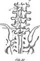
人間の椎骨(vertebrae)及び関係した接続性要素は、痛み及び機能不全の原因となる多岐に亙る疾患及び状態を生じ易い。これら疾患及び状態の内には、脊椎症、脊椎すべり症、椎骨不安定性、脊椎狭窄症、椎間板変性、椎間板ヘルニア、椎間板変性及びヘルニアがある。更に、椎骨及び関係した接続性要素は、骨折、靭帯の破断を含む損傷、及び椎弓切除を含む外科的処置の対象となる。 The human vertebrae and related connectivity elements are prone to a wide variety of diseases and conditions that cause pain and dysfunction. Among these diseases and conditions are spondylosis, spondylolisthesis, vertebral instability, spinal stenosis, disc degeneration, disc herniation, disc degeneration and hernia. In addition, the vertebrae and associated connectivity elements are subject to surgical procedures including fractures, injuries including ligament fractures, and laminectomy.
これらの疾患、状態、損傷及び処置に関係した痛み及び機能不全は、1つの椎骨の全体又は一部分が椎柱の他の椎骨から変位することに起因することがしばしばである。変位した椎骨又は変位した椎骨の一部分をそれらの正常な位置に回復し且つ、これらを椎柱内に固定するため多岐に亙る方法が開発されている。例えば、ねじ固定による観血的整復法は、現在使用されている方法の1つである。 Pain and dysfunction associated with these diseases, conditions, injuries and treatments are often due to the displacement of all or part of one vertebra from the other vertebrae of the vertebral column. A variety of methods have been developed to restore the displaced vertebrae or portions of the displaced vertebrae to their normal positions and secure them in the vertebral column. For example, open reduction by screw fixation is one of the methods currently used.
骨の2つ又はより多くの部分をピン、ねじ、ロッド及び板にて取り付ける外科的方法は、骨を取り巻く組織内に切開し且つ、接続すべき骨の部分に1つ又はより多くの穴を穿孔することを必要とする。骨の寸法、形態及び荷重条件の顕著な相違のため、従来の技術にて広範囲に亙る骨固定装置が開発されている。一般に、現在の標準的な治療方法は、癒合又は融合過程中、多岐に亙る金属線、ねじ、ロッド、板及び締結具を利用して骨の一部分を安定化させる。しかし、これらの方法は、罹患率、高額な費用、長期の入院及び開放手術に関係した痛みのような多岐に亙る不利点を伴う。 Surgical methods of attaching two or more parts of bone with pins, screws, rods and plates make an incision in the tissue surrounding the bone and make one or more holes in the part of the bone to be connected. Need to drill. Due to the marked differences in bone size, form and loading conditions, a wide range of bone fixation devices have been developed in the prior art. In general, current standard treatment methods utilize a variety of metal wires, screws, rods, plates and fasteners to stabilize a portion of bone during the fusion or fusion process. However, these methods come with a variety of disadvantages such as morbidity, high costs, long-term hospitalization and pain associated with open surgery.
このため、痛みが少なく且つ、合併症の可能性の少ない、変位した椎骨又は変位した椎骨の一部分を元の位置に戻し且つ、固定するための装置及び方法が必要とされている。好ましくは、装置は、最小侵襲性の方法を通じて植え込み可能なものとする。 Thus, there is a need for an apparatus and method for returning and fixing a displaced vertebra or portion of a displaced vertebra that is less painful and less likely to have complications. Preferably, the device is implantable through a minimally invasive method.
1つの実施の形態に従い、現所にて形成される整形外科用装置(a formed in place orthopedic device)が提供される。この装置は、キャビティを画成する外壁と、整形外科用装置を形成するキャビティ内の硬化可能な媒質とを備えており、この硬化可能な媒質は、約90分以内に約45℃以下の温度にて実質的に硬化(cure)する樹脂と、硬化剤との混合体を含み、この硬化可能な媒質は、装置が患者の身体内に配置される間、硬化して現所にて形成される整形外科用装置を形成する。 In accordance with one embodiment, an in-situ orthopedic device is provided. The device comprises an outer wall defining a cavity and a curable medium within the cavity forming the orthopedic device, the curable medium having a temperature of about 45 ° C. or less within about 90 minutes. And a mixture of a curing agent and a curing agent, the curable medium being cured and formed in situ while the device is placed in the patient's body. Forming an orthopedic device.
別の実施の形態に従い、骨固定装置(a bone fixation device)が提供される。この装置は、拡張可能な部材(inflatable member)を含む送込みカテーテルと、この拡張可能な部材内に保持された硬化可能な媒質と、入口を有する少なくとも2つのアンカーとを備えおり、該拡張可能な部材はアンカーの入口を貫通して伸びる。硬化可能な媒質は、約90分以内に少なくとも40.823kg(90lbs)の静圧縮曲げ値(ASTM F1717)を有する硬化した形態となるよう硬化するエポキシを備えている。 In accordance with another embodiment, a bone fixation device is provided. The device comprises a delivery catheter including an inflatable member, a curable medium retained within the expandable member, and at least two anchors having an inlet, the expandable The elongated member extends through the anchor inlet. The curable medium comprises an epoxy that cures to a cured form with a static compression bend value (ASTM F1717) of at least 90 lbs within about 90 minutes.
別の実施の形態に従い、整形外科用固定装置が提供される。この装置は、末端及び基端を有して、中央管腔を形成する細長い可撓性の管状本体と、少なくとも1つのポートを備える、管状本体の基端におけるマニホルドと、基端、末端、内部を有し、管状本体の末端に除去可能に取り付けられた拡張可能な部材と、該拡張可能な部材を拡張させる硬化可能な媒質であって、重量比にて約45乃至52%の芳香族ジエポキシド樹脂、重量比にて約19乃至23%の脂肪族ジエポキシド樹脂、重量比にて約20乃至29%のジアルキルアミン、約4乃至9%シクロアルキルアミンを含む硬化可能な媒質と、拡張可能な部材の基端に設けられた弁とを含む。 According to another embodiment, an orthopedic fixation device is provided. The device includes a distal flexible tube body having a distal end and a proximal end to form a central lumen, a manifold at the proximal end of the tubular body comprising at least one port, and a proximal end, a distal end, an interior And an expandable member removably attached to the distal end of the tubular body, and a curable medium for expanding the expandable member, the aromatic diepoxide being about 45-52% by weight A curable medium comprising a resin, about 19-23% by weight aliphatic diepoxide resin, about 20-29% dialkylamine by weight, about 4-9% cycloalkylamine, and an expandable member And a valve provided at the proximal end of the.
本発明の別の実施の形態に従って、患者の身体内の治療箇所にて整形外科用装置を形成する方法であって、内部に1つのチャンバを画成する外壁を患者の身体内の治療箇所に配置するステップと、硬化可能な媒質をチャンバ内に導入するステップとを含み、硬化可能な媒質は、液体の形態から約90分以内に少なくとも40.823kg(90lbs)の静圧縮曲げ値(ASTM F1717)を有する硬化した形態に硬化する、上記整形外科用装置を形成する方法が提供される。 In accordance with another embodiment of the present invention, a method of forming an orthopedic device at a treatment site in a patient's body, wherein an outer wall defining a chamber therein is the treatment site within the patient's body. And placing the curable medium into the chamber, the curable medium having a static compression bending value (ASTM F1717) of at least 90 lbs (90 lbs) within about 90 minutes from the liquid form. A method of forming the orthopedic device is set to a hardened form.
別の実施の形態に従う整形外科的骨折部を安定化する方法が提供される。この方法は、入口を有する少なくとも2つのアンカーを骨内に挿入するステップと、拡張可能なバルーンを備える整形外科用装置を骨に対して送り込むステップと、重量比にて約45乃至52%の芳香族ジエポキシド樹脂、重量比にて約19乃至23%の脂肪族ジエポキシド樹脂、重量比にて約20乃至29%のジアルキルアミン、約4乃至9%シクロアルキルアミンを備える硬化可能な媒質にて上記バルーンを拡張させるステップとを含む。上記整形外科用装置は上記入口を貫通して伸び、上記拡張により上記アンカーは互いに固定される。 A method for stabilizing an orthopedic fracture according to another embodiment is provided. The method includes the steps of inserting at least two anchors having an entrance into the bone, feeding an orthopedic device with an expandable balloon into the bone, and about 45-52% fragrance by weight. Balloon in a curable medium comprising an aliphatic diepoxide resin, about 19-23% by weight aliphatic diepoxide resin, about 20-29% dialkylamine by weight ratio, about 4-9% cycloalkylamine Expanding. The orthopedic device extends through the portal and the anchors are secured together by the expansion.
別の実施の形態に従う整形外科的骨折部を安定化する方法が提供される。この方法は、入口を有する少なくとも2つのアンカーを骨内に挿入するステップと、拡張可能なバルーンを備える整形外科用装置を入口を通して送り込むステップと、上記バルーンを液体の硬化可能な材料にて拡張させるステップとを含む。拡張させるステップは、上記アンカーを互いに固定して、硬化可能な材料が約90分以内に約45℃以下の温度にて実質的に硬化する。 A method for stabilizing an orthopedic fracture according to another embodiment is provided. The method includes inserting at least two anchors having an inlet into the bone, delivering an orthopedic device comprising an expandable balloon through the inlet, and expanding the balloon with a liquid curable material. Steps. The expanding step secures the anchors together, and the curable material substantially cures at a temperature of about 45 ° C. or less within about 90 minutes.
別の実施の形態において、現所にて形成される医療装置が提供される。この医療装置は、その内部にキャビティを画成する外壁と、キャビティ内にあり、医療装置を形成する硬化可能な媒質とを備え、該硬化可能な媒質は、約45℃以下の温度にて硬化する樹脂と、硬化剤との混合体を含み、上記硬化した媒質は、少なくとも68.039kg(150lbs)の静圧縮曲げ値(ASTM F1717)を有し、装置が患者の身体内に配置されている間、硬化可能な媒質が硬化して現所にて形成される医療装置を形成する。 In another embodiment, a medical device formed in situ is provided. The medical device includes an outer wall defining a cavity therein and a curable medium within the cavity forming the medical device, the curable medium being cured at a temperature of about 45 ° C. or less. The cured medium has a static compression bend value (ASTM F1717) of at least 68.039 kg (ASTF F1717) and the device is disposed within the patient's body. Meanwhile, the curable medium cures to form a medical device that is formed at the site.
好ましい実施の形態において、硬化可能又は硬化可能な材料は、重量比にて約45乃至52%の芳香族ジエポキシド樹脂、重量比にて約19乃至23%の脂肪族ジエポキシド樹脂、重量比にて約20乃至29%のジアルキルアミン、約4乃至9%シクロアルキルアミンを含む。特に好ましい実施の形態において、芳香族ジエポキシド樹脂は、ビスフェノールAのジグリシジルエーテル又はビスフェノールFのジグリシジルエーテルを含む。 In a preferred embodiment, the curable or curable material comprises about 45 to 52% by weight aromatic diepoxide resin, about 19 to 23% aliphatic diepoxide resin by weight, 20-29% dialkylamine, about 4-9% cycloalkylamine. In a particularly preferred embodiment, the aromatic diepoxide resin comprises diglycidyl ether of bisphenol A or diglycidyl ether of bisphenol F.
脂肪族ジエポキシド樹脂はグリシジルエーテルの1つ以上のアルカンジオールを含む。シクロアルキルアミンはN−アミノアルキルピペラジンである。ジアルキルアミンは、0分子式H2N−R−NH2に従ったものであり、ここでRは、枝分れ又は非枝分れC2−C10アルキル基である。硬化可能な媒質は、実質的に硬化したとき、少なくとも約27.216kg(約60lbs)、完全に硬化したとき、少なくとも約45.359kg(約100lbs)の静圧縮曲げ値(ASTM F1717)を有することが好ましい。媒質は、約90分以内に実質的に硬化することが好ましく、また、キュアリングは、約45℃以下、より好ましくは約43℃以下の温度にて行われる。本発明の更なる特徴及び有利な点は、特許請求の範囲及び添付図面と共に検討したとき、以下に記載する好ましい実施の形態の詳細な説明から当該技術分野の当業者に明らかになるであろう。The aliphatic diepoxide resin contains one or more alkanediols of glycidyl ether. Cycloalkylamine is N-aminoalkylpiperazine. The dialkylamine is according to the 0 molecular formula H2 N—R—NH2 , where R is a branched or unbranched C2 -C10 alkyl group. The curable medium has a static compression bend value (ASTM F1717) of at least about 60 lbs when substantially cured and at least about 100 lbs when fully cured. Is preferred. The medium preferably cures substantially within about 90 minutes and the curing is performed at a temperature of about 45 ° C. or less, more preferably about 43 ° C. or less. Additional features and advantages of the present invention will become apparent to those skilled in the art from the following detailed description of the preferred embodiment, when considered in conjunction with the claims and accompanying drawings. .
本発明の適用例は、主として脊柱の固定法に関して開示されるが、本明細書に開示された方法及び装置は、現所での取り付け部、増量部、支持部、固定部又はその他の要素を形成することが望まれる多岐に亙る医療用途の任意のものにて使用することを目的とするものである。 While the application of the present invention is primarily disclosed with respect to spinal fixation methods, the methods and apparatus disclosed herein may include in-situ attachments, bulking parts, support parts, fixation parts or other elements. It is intended for use in a wide variety of medical applications that are desired to be formed.
本発明に従って現所にて補綴具を形成する1つの有利な点は、相対的に大きいインプラントを治療箇所にて形成することを可能にしつつ、最小侵襲性アクセス経路を通じて治療箇所にアクセスすることが可能な点である。このことは、開放外科手術の切開又はその他の侵襲的アクセス手順が回避されるため、手術に伴う罹患率を最小にすることを可能にする。更に、本発明に従って現所にて形成することは、注入可能で硬化可能な媒質が該媒質が注入されるキャビティ又は可撓性容器の形状をとることが可能であるため、多岐に亙る特定の形状又は所定の形状の任意のものを有するインプラントを形成することを許容する。 One advantage of forming a prosthesis in-situ in accordance with the present invention is that the treatment site can be accessed through a minimally invasive access path while allowing a relatively large implant to be formed at the treatment site. This is possible. This makes it possible to minimize the morbidity associated with surgery, as open surgical incisions or other invasive access procedures are avoided. Furthermore, in-situ formation according to the present invention can be in a wide variety of specific forms because the injectable and curable medium can take the form of a cavity or flexible container into which the medium is injected. It is allowed to form an implant having a shape or any of a predetermined shape.
本発明の方法及び装置は、予め形成された補綴具が適合せず又は通り抜けることができない湾曲し且つ、更に蛇行した経路に沿って身体内の治療箇所にアクセスすることを更に可能にする。細長い可撓性の管状のカテーテル本体の末端に除去可能に連結された本発明の取り外し可能な拡張可能な補綴具は、以下により詳細に開示するように脊柱、長骨、短骨及び関係した靭帯及び腱のような多岐に亙る整形外科的適用例の任意のものの現所にて拡張可能又はその他硬化可能な補綴具を経皮的に、外科的に又は経管腔的に前進させ且つ、展開させる寸法とすることができる。更に、展開カテーテル及び補綴具は、心臓血管系、胃腸路、胆管、尿生殖路又は気道(例えば、気管気管支樹)を通じて経管腔的に進行し得る寸法とすることができる。このように、装置は、人工的アクセス経路、及び自然に生じる管腔及び中空の器官を通して前進させることができる。本発明の現所にして装置を形成する技術の追加的な適用例は、本明細書の開示内容を参照して当該技術分野の当業者に明らかになるであろう。 The method and apparatus of the present invention further allows access to the treatment site in the body along a curved and serpentine path that the preformed prosthesis does not fit or cannot pass through. The removable expandable prosthesis of the present invention removably coupled to the distal end of an elongate flexible tubular catheter body is a spinal column, long bone, short bone and related ligament as disclosed in more detail below. Advancing and deploying percutaneously, surgically or transluminally a expandable or other curable prosthesis in the field of any of a wide variety of orthopedic applications such as tendons It can be made into the size to make. Further, the deployment catheter and prosthesis can be sized to be transluminally advanced through the cardiovascular system, gastrointestinal tract, bile duct, urogenital tract or airway (eg, tracheobronchial tree). In this way, the device can be advanced through artificial access pathways and naturally occurring lumens and hollow organs. Additional applications of techniques for forming devices in the field of the present invention will become apparent to those skilled in the art with reference to the disclosure herein.
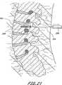
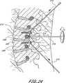
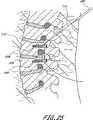
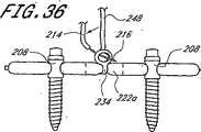
脊柱固定の適用例に関して、本発明は、入口のようなコネクタを有する1つ又は2つ又はより多くの骨アンカーを少なくとも第一及び第二の隣接し又は隣接しない椎骨内に挿入するステップを含む。植込み型、挿入可能な整形外科用装置が入口を通して挿入され且つ、拡張して骨アンカーに対し係止し、骨構成要素を安定化させる。植込み型装置を除去可能に支持する送込みカテーテルを備える展開システムが提供され、経皮的又は最小侵襲性の仕方にて方法を実行し、手術に伴う患者に対する外傷を最小にする。 For spinal fixation applications, the present invention includes the step of inserting one or two or more bone anchors having connectors such as portals into at least first and second adjacent or non-adjacent vertebrae. . An implantable, insertable orthopedic device is inserted through the portal and expands to lock against the bone anchor and stabilize the bone component. A deployment system comprising a delivery catheter that removably supports an implantable device is provided to perform the method in a percutaneous or minimally invasive manner to minimize trauma to the patient associated with the surgery.
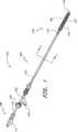
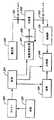
図1に示した展開システムは、植込み型の拡張可能な整形外科用装置(inflatable orthopedic device)102を展開させる送込みカテーテル(delivery catheter)100を備えている。送込みカテーテル100は、基端106及び末端108を有する細長い可撓性の管状本体104を有することが好ましい。しかし、直接、直線状にアクセスすることを目的とする特定の適用例の場合、管状本体104は、実質的に剛性なものとすることができる。管状本体104は、装置の所望の機能に依存して本体を貫通して軸方向に伸びる1つ又はより多くの通路又は管腔を有する。 The deployment system shown in FIG. 1 includes a
送込みカテーテル100の全長及び断面寸法は、所期の臨床的適用例に依存して変更することができる。例えば、腰椎及び(又は)仙骨椎骨の経皮的又は最小侵襲性癒合を目的とする装置において、管状本体104は、全体として、約15cm乃至約50cmの範囲の長さと、約2mm乃至約6mmの範囲の直径とを有するものとする。 The overall length and cross-sectional dimensions of the
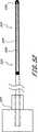
管状本体104の基端106から管状本体104の末端108まで拡張管腔130のような管腔を通って伸びる(図2参照)、除去可能な細長い補強ワイヤー122を設けることにより、送込みカテーテル100の経皮的挿入を容易にすることができる。選択的に、補強ワイヤー122は、整形外科用装置102の末端118内に且つ、該末端まで全経路を亙って伸びて、装置102に対する支持力及び縦強度を提供し、このことは組織に貫入する間、望ましいことであろう。補強ワイヤー122の末端は、長さ約8cmのコイルに接続し、ある程度の可撓性を許容することができる。 By providing a removable elongated reinforcing
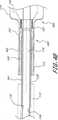
図2には、内側スリーブ110と、外側スリーブ112とを(正確な縮尺ではなく)示す、細長い本体104に沿った断面図が示される。内側スリーブ110は第一の拡張管腔130を画成する一方、第二の通気管腔132は内側スリーブ110と外側スリーブ112との間の環状空間により画成される。拡張管腔130は、内側スリーブ110において基端側開口部127を通って摺動する形態にて細長い補強ワイヤー122を受け入れ得るようにされている一方、内側スリーブは、カテーテルマニホルド124のポート126を介して外側スリーブ112内に軸方向に伸びている。図示した実施の形態は、二重管腔、同心状又は同軸状の形態を有するが、これと代替的に、カテーテルの所望の能力に依存して、3つ又はより多くの管腔を設けてもよい。利用されるならば、除去可能な補強ワイヤーを収容するため、また、植込み型装置の拡張を容易にするため、単一管腔カテーテルを設けることもできる。これと代替的に、2又はより多くの管腔カテーテルの軸を管腔が横に並んだ形態にて製造し、押出し成形し又はその他の方法で形成してもよい。 FIG. 2 shows a cross-sectional view along the
展開装置100は、細長い管状本体104の基端106に配置されたマニホルド124を更に備えている。カテーテルマニホルド124は、ヘルスケア従事者に対する操作ハンドルを提供し且つ、拡張ポート126及び通気ポート128を支持する。拡張ポート126又は通気ポート128の一方又は双方には、当該技術分野にて既知であるように、関係した装置に接続するためのルアロック接続具のような継手を設けることができる。例えば、拡張ポート126におけるルア又はその他のコネクタは、従来の方法にて加圧された拡張媒質源に接続することを容易にする。通気ポート128は、注射器又はその他の装置に接続し、硬化可能な媒質を注入する前に、真空圧を吸引し、バルーンから空気を排出することができる。 The
マニホルド124はまた、X線透視装置にて送り込み装置を視覚化することを可能にし得るよう放射線不透過性の造影流体を注入することを許容する注入ポートを有することもできる。基端マニホルド124は、PTFE、ABS、ナイロン、ポリエチレン、ポリカーボネート又は当該技術分野にて既知のその他のもののような多岐に亙る既知の適宜な材料の任意のものにて機械加工し又は射出成形することができる。内側スリーブ110の周りにて確実に密封し、流体の損失を防止する精密ガスケットを設けることもできる。
押出し成形、共押出し成形、被覆、接着剤、及び成形を含む、カテーテルを製造する技術は、全体として当該技術分野にて既知である。本発明のカテーテルは、従来の方法にて製造されることが好ましい。カテーテルの細長い軸は、ナイロン、PEBAX、PEEK、PTFE、PE又はカテーテル技術にて既知のその他のもののようなポリマーを使用して押出し成形することができ、これら材料の剛性は適宜に選ぶことができる。材料の選択は、所望の特徴に基づいて相違する。継手は接合されることが好ましい。継手を接合するため生体適合性接着剤又は熱接合法を使用することができる。バルーン及びステントは、従来の方法にて又は任意の適宜な仕方にて形成してもよい。 Techniques for manufacturing catheters, including extrusion, coextrusion, coating, adhesive, and molding, are generally known in the art. The catheter of the present invention is preferably manufactured by a conventional method. The elongated shaft of the catheter can be extruded using polymers such as nylon, PEBAX, PEEK, PTFE, PE or others known in the catheter art, and the stiffness of these materials can be chosen accordingly. . The choice of material will vary based on the desired characteristics. The joint is preferably joined. Biocompatible adhesives or thermal bonding methods can be used to join the joints. Balloons and stents may be formed in a conventional manner or in any suitable manner.
展開システム100は、拡張可能又は現所にて形成される固定板又はロッドとして、脊柱の融合適用例にて機能することのできる植込み型の拡張可能な整形外科用装置102を更に備えている。植込み型装置102は、管状本体104の末端により除去可能に支持し、拡張管腔130が拡張可能な装置102の内部キャビティ146と連通するようにする。このように、拡張媒質をマニホルド124に配置された拡張ポート126(又は開口部127)を通じて注入し、キャビティ146を充填することができる。 The
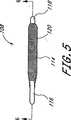
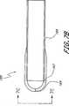
バルーン114とすることのできる植込み型装置102は、基端116と、末端118と、可撓性の壁148とを有する。バルーン114は、バルーン血管形成技術にて既知の多岐に亙る重合系材料の任意のものにて形成することができる。これらの材料は、例えば、ポリエチレン、ポリエチレン混合体又はナイロンのような柔軟な材料及びポリエチレンテレフタレートのような実質的に非柔軟な材料を含む。本明細書の開示を参照して当該技術分野の当業者により明らかであるように、多岐に亙るその他の生体適合性ポリマーの任意のものを利用することができる。 The
バルーン114は、所望の物理的性質に依存して、単層又は多層とすることができる。1つの実施の形態において、バルーンは、ステント又はその間に狭持された複数の軸方向に伸びる支持ストリップのような補強構造体を有する2つの層から成るものとする。1つの代替的な実施の形態において、バルーン114は、硬化可能な媒質を制止する第一の内層を備えている。第二の層である外層は、第一の層の周りにて同軸状に配置され、また、複数の開口又は微細孔構造体が設けられている。基端の注入ポートとバルーンの内層及び外層との間の空間とを連通させるため、注入管腔が細長い管状本体に設けられている。このようにして、多岐に亙る薬剤の任意のものを保持することのできる流体を治療箇所を取り囲む組織内に注入することができる。適宜な構造体及び製造上の考慮事項は、その内容の全体を参考として引用し本明細書に含めた、クロッカー(Crocker)その他の者に対する米国特許明細書5,295,962号に開示される。 The
バルーン114に対する円筒状の形態が示されるが、多岐に亙る代替的な断面形態の任意のものを使用することができる。植込み型の拡張可能な整形外科用装置102の全長、直径及び肉厚は、特定の治療及びアクセス箇所に依存して変更することができる。1つの実施の形態において、装置102は、隣接する椎骨を固定するため、約2乃至12cm、また、しばしば約5cm乃至約8cmの範囲の延長した長さを有する。装置102は、全体として約0.5乃至2cmの範囲の拡大した直径を有する。 Although a cylindrical configuration for the
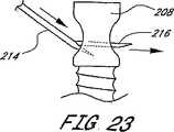
バルーン114の長さは、第一のアンカーと第二のアンカーとの間の予想される距離、又は2つ以上のアンカーを有する実施の形態において、最大の軸方向分離距離を有するアンカーの間に予想される距離に基づくものとする。例えば、成人の2つの隣接する腰椎(例えば、L4−L5)を融合させる融合適用例において、第一及び第二のアンカーは、全体として約5cm乃至約8cmの範囲の距離だけ分離させる。好ましくは、バルーン114の軸方向長さは、アンカーの内側間隔よりも十分に長く、例えば、図9に示すように、バルーンの一部分がアンカー開口の「遠方」側にて膨張するのを許容するようにする。このように、上述したアンカーの内側距離に対するバルーンの長さは、全体としてアンカーの内側距離とアンカーの直径との合計値を少なくとも約0.5cmだけ上廻るものとする。好ましくは、バルーンは入口を越えて少なくとも約1cm伸びるようにする。 The length of the
例えば、腰椎におけるように、第一の椎骨が第二の椎骨に取り付けられ、第二の椎骨が少なくとも第三の椎骨により第一の椎骨から分離される適用例にて使用する場合、アンカーの内側距離は全体として約10cm乃至約20cmの範囲にある。当該技術分野の当業者に理解されるように、3つ又はより多くの椎骨を固定する場合、中間椎骨又は複数の椎骨は、通常、拡張可能なバルーン114に接続されるが、必ずしも接続する必要はない。このように、1つの適用例において、バルーン114は、第一の取り付け箇所にて第一の骨に及び第二の取り付け箇所にて第二の骨に接続し、1つ又はより多くの中間の骨はバルーン114に接続しない。別の適用例において、第一のアンカーと第二のアンカーとの間に少なくとも第三のアンカーが提供され、バルーン114は、第一、第二及び第三のアンカーの各々における開口を通じてねじ込む。2つの取り付け箇所の間に介在する椎骨又はその他の骨又は構造体を取り付けるか又は取り付けないままにする方が望ましいかどうかは、患者の特定の状況を考慮して決定される臨床的判断事項である。 For example, in an application where the first vertebra is attached to the second vertebra and the second vertebra is separated from the first vertebra by at least a third vertebra, such as in the lumbar vertebra, the interior of the anchor The distance is generally in the range of about 10 cm to about 20 cm. As will be appreciated by those skilled in the art, when fixing three or more vertebrae, the intermediate vertebra or vertebrae are usually connected to the
バルーン114の主たる機能は、その内部に注入した後、硬化可能な媒質の形状に影響を与え又は形状を制御することである。植込み型バルーン114は、通常、長期間に亙って圧力を規制する必要はない。このため、従来の血管形成用又はその他の拡張バルーンと比較してより大きい設計上の自由を許容することができる。例えば、バルーン114は、上記に説明したように、薬を送り込むか又は骨に組み込み及び(又は)柔軟な組織の内部成長を許容するかの何れかのため、多孔質とすることができる。 The main function of the
PMMAのような本発明に関して利用することのできる特定の硬化可能な媒質は、従来の血管形成用バルーン拡張媒質と比較して、予め硬化した形態において著しく高粘度を有する。更に、バルーン114は顕著な圧力を保持することを目的としないため、高圧血管形成法用の材料のような従来の高強度材料は不要である。このことは、バルーン血管形成適用例に利用される技術を含む、多岐に亙る方法の任意の方法にてバルーン114を製造することを許容する。更に、バルーン114(又はバルーン状構造体)は、織地ファイバ、不織ファイバ、布地、織線又は編上げ線のような金属メッシュ及び炭素の多岐に亙るものの任意のものにて製造することができる。ePTFE及びダクロン(Dacron)(登録商標名)のような生体適合性布地又はシート材料を使用することもできる。 Certain curable media that can be utilized in connection with the present invention, such as PMMA, have a significantly higher viscosity in a precured form as compared to conventional angioplasty balloon expansion media. Furthermore, since the
硬化可能な媒質は、ポリメチルメタアクリレートのような急速凝固、低密度、液体ポリマー又はポリマー前駆体であることが好ましい。しかし、多岐に亙るエポキシ、ポリウレタン又はポリウレタン−シリコーンの混合体の任意のものを含む、必要とされる補強又は凝固特徴を提供する多岐に亙るその他の材料の任意のものを使用することができる。 The curable medium is preferably a rapidly solidified, low density, liquid polymer or polymer precursor such as polymethylmethacrylate. However, any of a wide variety of other materials that provide the required reinforcement or solidification characteristics can be used, including any of a wide variety of epoxies, polyurethanes or polyurethane-silicone mixtures.
脊柱固定法にて使用される、ロッド形状の拡張可能な容器に関して、硬化可能な媒質の物理的必要条件は、ロッドの長さ及び直径並びに植え込み箇所により要求される物理的条件に依存する。特定の実施の形態の場合、ポリメチルメタアクリレート、エポキシ、ポリウレタン又はその他の特定の材料は、十分な物理的性質を提供し又は提供しないこともある。硬化可能な材料の物理的性質は、炭素繊維、ケブラー又はチタンロッド、織地又はレーザエッチングした金属管状ステント又は当該技術分野にて理解されるようなその他の補強材の選択は、本明細書の開示内容を参照して、当該技術分野の当業者による日常的な実験を通じて任意の特定の植込みシステムに対して最適化することができる。 For rod-shaped expandable containers used in spinal fixation methods, the physical requirements of the curable medium depend on the length and diameter of the rod and the physical requirements required by the implantation site. For certain embodiments, polymethylmethacrylate, epoxy, polyurethane or other specific materials may or may not provide sufficient physical properties. The physical properties of the curable material are selected from carbon fiber, Kevlar or titanium rods, woven or laser-etched metal tubular stents or other reinforcements as understood in the art. With reference to the content, it can be optimized for any particular implantation system through routine experimentation by one of ordinary skill in the art.
2部分エポキシ又は2部分ポリウレタンのような接合剤中に埋め込まれた炭素ファイバのような特定の複合材料は、本発明のインプラントを形成するとき特に有用であることが判明している。例えば、約0.0762mm(0.003インチ)乃至約0.1778mm(0.007インチ)の範囲の直径を有する黒鉛(炭素ファイバ)が約3,000乃至約12,000のファイバから成る束(トウ)にて提供される。この目的のために有用な1つの典型的なファイバは、ユタ州、ソルトレイクシティのヘクセルカーボンファイバ(Hexcel Carbon Fibers)により部品番号HS/CP−5000/IM7−GP 12Kとして製造されるものである。好ましくは、トウの引張り強度は、約5,000乃至7,000Mpaの範囲にあるものとする。トウの引張り弾性率は、約250乃至約350Gpaの範囲内にある。 Certain composite materials such as carbon fibers embedded in a bonding agent such as a two part epoxy or two part polyurethane have been found to be particularly useful when forming the implants of the present invention. For example, a bundle of graphite (carbon fiber) having a diameter ranging from about 0.003 inches to about 0.007 inches (carbon fibers) consisting of about 3,000 to about 12,000 fibers ( Provided by Tow). One exemplary fiber useful for this purpose is that manufactured by Hexcel Carbon Fibers, Salt Lake City, Utah, as part number HS / CP-5000 / IM7-GP 12K. is there. Preferably, the tensile strength of the tow is in the range of about 5,000 to 7,000 Mpa. The tensile modulus of tow is in the range of about 250 to about 350 Gpa.
特定の実施の形態において、固定ロッドは、補強ファイバ又はロッドを必要とせずに形成される。かかる実施の形態において、硬化可能な材料自体がインプラントにて使用するのに十分な物理的性質を呈する。 In certain embodiments, the fixed rod is formed without the need for reinforcing fibers or rods. In such embodiments, the curable material itself exhibits sufficient physical properties for use in the implant.
全体として、本発明に従った複合ロッドは、約45.359乃至約90.719kg(約100lbs乃至約200lbs)、好ましくは、68.039kg(150lbs)以上の静圧縮曲げ値(ASTM F1717による)を示す。複合ロッドは、約33.9乃至約56.5Nm(約300乃至約500インチポンド)範囲内、また、全体として約45.2Nm(約400インチポンド)以上の静止捩れ(ASTM F1717による)を示す。ロッドは、5Hzにて少なくとも約500万回のサイクルに達することが好ましい。これらのパラメータの各々は、その写しを付属書Aとして本明細書に添付し、その内容の全体を参考として引用し本明細書に含めた、アメリカ試験材料協会(ASTM)基準F1717−96に記載された方法に従って測定することができる。 Overall, the composite rod according to the present invention has a static compression bending value (according to ASTM F1717) of about 45.359 to about 90.719 kg (about 100 lbs to about 200 lbs), preferably 68.039 kg (150 lbs) or more. Show. The composite rod exhibits a static twist (according to ASTM F1717) in the range of about 33.9 to about 56.5 Nm (about 300 to about 500 inch-pounds) and generally about 45.2 Nm (about 400 inch-pounds) or more. . The rod preferably reaches at least about 5 million cycles at 5 Hz. Each of these parameters is described in the American Society for Testing and Materials (ASTM) standard F1717-96, a copy of which is attached hereto as Appendix A, the entire contents of which are incorporated herein by reference. Can be measured according to published methods.
上述した炭素ファイバは、約30乃至約60の束の範囲内にて、選択的に、直径8mm及び長さ8cmのNi−Tiステントと共に、萎んだバルーン内に充填する。多岐に亙るステントの任意のものが利用可能であるが、1つの有用な構造体は、スマートステント(コルディス(Cordis))と同様であり、このステントは、構造体を無傷の状態に保ち且つ、植え込んだ構造体に対し構造的強度を提供する。 The carbon fibers described above are packed in a deflated balloon, optionally in the range of about 30 to about 60 bundles, with Ni-
次に、約100乃至約1000cpsの範囲の粘度を有する1部分又は2部分エポキシを粘度、バルーンの強度及びその他の設計上の考慮事項に依存して、ポンプ及び約4ATM乃至10ATM又はそれ以上の範囲の圧力を使用する等により圧力を加えてバルーン内に注入する。ポンプは、エポキシがファイバの全てを湿らせることを保証するのに十分な時間及び十分な圧力にて作動させる。これは、約10分乃至約1時間以上の範囲とし、また、ポンプを約5ATM圧力にて作動させる1つの適用例において、少なくとも約1/2時間であることを必要とする。エポキシの粘度、注入圧力、注入流量、詰め込んだ炭素ファイバの密度、本開示を参照して当該技術分野の当業者に明らかであろうその他の変数に依存し、特定の方法のパラメータを最適化することができる。 Next, a one-part or two-part epoxy having a viscosity in the range of about 100 to about 1000 cps, depending on the viscosity, balloon strength, and other design considerations, ranges from about 4 ATM to 10 ATM or more. The pressure is applied, for example, by using a pressure of 5 to inject into the balloon. The pump is operated for a time and sufficient pressure to ensure that the epoxy wets all of the fiber. This ranges from about 10 minutes to about 1 hour or more, and in one application where the pump operates at about 5 ATM pressure, requires at least about 1/2 hour. Optimize the parameters of a particular method depending on the viscosity of the epoxy, injection pressure, injection flow rate, density of the packed carbon fiber, and other variables that will be apparent to those skilled in the art with reference to this disclosure be able to.
1つの代替的な実施の形態において、約15乃至約45゜の編上げ角度を有する炭素ファイバが利用される。編上げ部は、平織り形態とし、また、例えば、コンポジットストラクチャーズテクノロジー(Composite Structures Technology)(カリフォルニア州、テハチャピ)から入手することができる。45゜の編上げ炭素ファイバスリーブの12.7mm(0.5インチ)の直径をバルーンの中心に配置する。この編上げスリーブは、寸法的にバルーンの内径に適合する。また、直径7.62mm(0.3インチ)の編上げ炭素スリーブ(同様に、45゜×45゜平織り)を外側編上げ炭素ファイバスリーブ内にてバルーン内に同心状に配置することもできる。その後、単一方向ファイバを内側編上げ炭素スリーブのID内に導入する。単一方向ファイバは、2つの編上げスリーブの間の環状空隙内にも導入される。バルーンの容積当たりのファイバの容積は、全体として約40%乃至約55%の範囲にある。上記の構造体をねじの入口内に配置した後、約100乃至約1000cpsの範囲の粘度を有するエポキシ混合体を10大気圧にてバルーン内に注入する。 In one alternative embodiment, carbon fiber having a braid angle of about 15 to about 45 ° is utilized. The braided portion is in plain weave form and can be obtained from, for example, Composite Structures Technology (Tehachapi, CA). A 12.7 mm (0.5 inch) diameter of a 45 ° braided carbon fiber sleeve is placed in the center of the balloon. This braided sleeve is dimensionally adapted to the inner diameter of the balloon. Also, a knitted carbon sleeve (also 45 ° × 45 ° plain weave) having a diameter of 7.62 mm (0.3 inches) can be concentrically disposed within the balloon within the outer knitted carbon fiber sleeve. Thereafter, the unidirectional fiber is introduced into the ID of the inner braided carbon sleeve. A unidirectional fiber is also introduced into the annular gap between the two braided sleeves. The overall fiber volume per balloon volume is in the range of about 40% to about 55%. After placing the above structure in the screw inlet, an epoxy mixture having a viscosity in the range of about 100 to about 1000 cps is injected into the balloon at 10 atmospheres.
上記の複合構造体について、炭素ファイバの例を使用して説明したが、完成した製品の物理的性質を向上させるため、多岐に亙る繊維の任意のものをバルーン内に配置することができる。例えば、ケブラーファイバ、PEEK及び任意の多岐に亙る代替例のものを使用することができる。一般に、ファイバは、装置の送り込み容易性を向上させ得るよう直径が小さく、極めて高引張り強度及び高弾性率を提供することが好ましい。 While the above composite structure has been described using the example of carbon fiber, any of a wide variety of fibers can be placed in the balloon to improve the physical properties of the finished product. For example, Kevlar fiber, PEEK, and any of a wide variety of alternatives can be used. In general, it is preferred that the fiber be small in diameter so as to improve the ease of feeding of the device and provide very high tensile strength and high modulus.
編上げスリーブを使用することは、一方向ファイバを常時、バルーン内にて均質な仕方にて分配する能力に加えて、捩れ荷重の結果、せん断応力に対するより大きい構造的抵抗を発生させる。このことは、インプラントの性能を向上させるものと考えられる。 The use of a braided sleeve generates greater structural resistance to shear stress as a result of torsional loads, in addition to the ability to always distribute unidirectional fibers in a homogeneous manner within the balloon. This is thought to improve the performance of the implant.
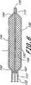
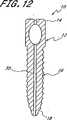
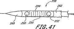
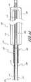
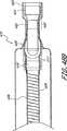
本発明に従った複合的な形成可能なロッドの1つの構造が図4Cに示される。上述したように、外側バルーン又はその他の封込め構造体114が提供される。ステントのような補強要素120がバルーン内に同心状に配置されている。外側支持管121は、図示した実施の形態にてステント内に配置されているが、これと代替的に、外側支持管121をステント120の外部に同心状に配置してもよい。外側支持管121は、1つの実施の形態にて、上述したように捩れ抵抗性を向上させ得るように互いに45゜の角度にて延伸させたクロスストランドを有する直径12.7mm(0.5インチ)の編上げ炭素ファイバ管である。 One structure of a composite formable rod according to the present invention is shown in FIG. 4C. As described above, an outer balloon or
内側支持管123が外側支持管121から半径方向内方に隔てられている。内側支持管123は、1つの実施の形態において、上述した特徴を有する直径7.62mm(0.3インチ)の編上げ炭素ファイバスリーブを備えている。第一の複数の単一方向ファイバ125が外側支持管121と内側支持管123の間の環状空間内にて軸方向に延伸されている。第二の複数の一方向炭素ファイバ127が内側支持管123内に配置されている。 The inner support tube 123 is spaced radially inward from the
本明細書に記載した教示に従って多岐に亙る代替的な構造の任意のものを容易に利用することができる。例えば、3つ又はより多くの管状支持管を利用することができる。色々な構成要素の層状の配置順序は変更可能である、完成した装置の所望の性能に依存して、その他の造作部を追加し又は廃止してもよい。更に、バルーン114は、1つの実施の形態において、ナイロン単一層バルーンであるが、その他の材料を利用してもよい。更に、ステント、ワイヤー又はその間に狭持された織地管状支持構造体のような支持構造体を有し又は有さずに多層バルーンを利用することができる。 Any of a wide variety of alternative structures can be readily utilized in accordance with the teachings described herein. For example, three or more tubular support tubes can be utilized. Depending on the desired performance of the completed device, other features may be added or eliminated depending on the desired ordering of the layered arrangement of the various components. Further, the
代替的な実施の形態において、形成可能なロッドは、図4Cに示した1つ又はより多くの補強構造体を備えていない。かかる1つの代替的な実施の形態において、第一の複数の一方向ファイバ125及び第二の複数の一方向ファイバ127は存在しない。かかる別の代替的な実施の形態において、ファイバ125、127を備え又は備えなくてもよい内側支持管123、外側支持管121及び(又は)ステント120は、ロッド内に存在しない。 In an alternative embodiment, the formable rod does not include one or more reinforcing structures shown in FIG. 4C. In one such alternative embodiment, the first plurality of
その他の実施の形態は、外側バルーン又はメッシュのような封込め構造体を備えており、また、図4Cに示した上述した補強構造体は備えていない。かかるその他の実施の形態において、硬化可能な媒質のみにて必要とされる強度及びその他の物理的特徴を有するロッドを形成するのに十分である。より少ない補強又は支持構造体を有し又は全く有しない実施の形態は、上述したのと実質的に同一の仕方にて形成され、硬化可能な媒質は、流体の形態にて封込め構造体内に注入され且つ、その後、硬化することが許容される。 Other embodiments include a containment structure such as an outer balloon or mesh, and do not include the above-described reinforcement structure shown in FIG. 4C. In such other embodiments, it is sufficient to form a rod having the strength and other physical characteristics required only with a curable medium. Embodiments with less or no reinforcement structure are formed in substantially the same manner as described above, and the curable medium is contained within the containment structure in fluid form. Injected and then allowed to cure.
金、白金又はタンタルのような材料で出来たマーカバンドは、また、蛍光透視法による視覚化を容易にすべくバルーン上に配置することもできる。これと代替的に、エポキシ又はその他の硬化可能な媒質を注入する前に、タンタル粉末のような放射線不透過性材料を炭素ファイバ内に噴霧し、配置する間の視覚化を許容するようにしてもよい。 A marker band made of a material such as gold, platinum or tantalum can also be placed on the balloon to facilitate visualization by fluoroscopy. Alternatively, before injecting the epoxy or other curable medium, a radiopaque material such as tantalum powder can be sprayed into the carbon fiber to allow visualization during placement. Also good.
エポキシ又はポリウレタン材料は、37℃にて相対的に速い硬化速度を有することが好ましい。低粘度(約100乃至約1000cps以下)は、送込みカテーテルを通しての迅速な経管腔的導入及び隣接する炭素ファイバ間の相対的に小さい組織間空間を湿潤化するのを容易にする。更に、ポリマーは、放射線不透過性であることが好ましい。重合化は、取り囲む組織に対する熱損傷を最小にし又は防止するため、最小発熱性であることが好ましい。本発明にて使用可能である1つのエポキシは、エポキシテクノロジーインク(Epoxy Technology,Inc.)(マサチューセッツ州、ビルエリカ)から入手可能であるエポテック(Epotek)301である。このエポキシは、展開した後、37℃にて約3乃至4時間以内にその強度の50乃至60%に達する。これらに近似する特徴を有する接合剤を使用すれば、患者は、部分的硬化(例えば、少なくとも約50%、好ましくは60%以上)を実現し得るよう約3時間又は4時間の当初の硬化期間、転らないよう制止することができ、また、完全に硬化し得るよう、次の8時間乃至12時間又はそれ以上のような二次的硬化期間、寝たままにすることができる。触媒に対する成分及びフォミュレーションの比を変化させることにより、より迅速な硬化時間(好ましくは、約1時間以内に完全に硬化)を有する2部分エポキシ又はポリウレタンのその他のフォミュレーションを調合することができる。また、触媒のような促進剤を使用し又は以下に詳細に説明するように、熱を加えることにより、硬化時間を促進することもできる。 The epoxy or polyurethane material preferably has a relatively fast cure rate at 37 ° C. Low viscosity (about 100 to about 1000 cps or less) facilitates rapid transluminal introduction through the delivery catheter and wetting of the relatively small inter-tissue space between adjacent carbon fibers. Furthermore, the polymer is preferably radiopaque. Polymerization is preferably minimally exothermic in order to minimize or prevent thermal damage to the surrounding tissue. One epoxy that can be used in the present invention is Epotek 301 available from Epoxy Technology, Inc. (Bill Erica, Mass.). The epoxy reaches 50-60% of its strength within about 3-4 hours at 37 ° C. after deployment. By using a bonding agent having characteristics approximating these, the patient can achieve an initial cure period of about 3 hours or 4 hours to achieve partial cure (eg, at least about 50%, preferably 60% or more). It can be stopped from rolling, and can remain asleep for a secondary cure period, such as the next 8 to 12 hours or more, so that it can fully cure. Formulating two part epoxy or other formulations of polyurethane with faster cure times (preferably fully cured within about 1 hour) by varying the ratio of components to catalyst and formulation Can do. It is also possible to accelerate the cure time by using a promoter such as a catalyst or by applying heat, as will be described in detail below.
特定の実施の形態に従い、好ましい硬化可能な媒質は、次の特徴の1つ以上を備えている;即ち、(1)動物の体温に近い温度(約35℃乃至42℃)にて完全に硬化すること;(2)穏やかな発熱硬化振舞いを呈し、媒質は硬化反応のため、約45℃以下の温度、好ましくは約42℃以下まで自己加熱し、硬化する間の付近の生物組織に対する熱損傷の危険性を減少させることを意味すること;(3)硬化後の緊密な密着状態を維持し得るよう、硬化する間、収縮を殆ど又は全く呈しないこと;(4)好ましくは、約100乃至1000cps、より好ましくは、約100乃至400cpsの硬化前粘度を有すること;(5)混合/初期化/励起後、約30分以内、好ましくは約15分以内の有効寿命(「貯蔵寿命」)を有すること(即ち、注入を許容するのに十分に低粘度であること);(6)混合等により、初期化した後、約30、40、50、60、70、80、90分又はそれ以内の時間を含む、好ましくは約20乃至100分以内に実質的に硬化すること(即ち、材料の硬いロッドを形成することができること);(7)約31.752、36.287、40.823、45.359kg(約70、80、90、100lbs)を含む、少なくとも約27.216kg(約60lbs)(力)の静止圧縮曲げ値(ASTM F1717による)を有する実質的に硬化したロッドを形成すること;(8)好ましくは、約10乃至12時間の初期化以内に、約49.895、54.431、58.967、63.509、72.575、77.111、81.647、86.183kg(約110、120、130、140、160、170、180、190lbs)を含む、約45.359乃至90.719kg(約100乃至200lbs)(力)の範囲、好ましくは約68.039kg(約150lbs)以上の静止圧縮曲げ値(ASTM F1717による)を有する完全に硬化したロッド(補強せず)を形成すること;(9)約33.9乃至約56.5Nm(約300乃至約500インチポンド)、好ましくは約45.2Nm(約400インチポンド)以上の範囲内の静止捩れ(ASTM F1717による)を有する完全に硬化したロッド(補強せず)を形成すること;(10)生体適合性固体物を形成することである。硬化可能な媒質の特に好ましい実施の形態は、上記の特徴の殆ど又は全てを示すものである。 In accordance with certain embodiments, preferred curable media have one or more of the following characteristics: (1) fully cured at a temperature close to the body temperature of the animal (about 35 ° C. to 42 ° C.) (2) It exhibits a mild exothermic curing behavior, and the medium self-heats to a temperature of about 45 ° C. or lower, preferably about 42 ° C. or lower, due to the curing reaction, and heat damage to nearby biological tissue during curing (3) exhibit little or no shrinkage during curing to maintain a tight adhesion after curing; (4) preferably about 100 to Have a pre-cure viscosity of 1000 cps, more preferably about 100 to 400 cps; (5) a useful life (“shelf life”) within about 30 minutes, preferably within about 15 minutes after mixing / initialization / excitation. Having (ie (6) including a time of about 30, 40, 50, 60, 70, 80, 90 minutes or less after initialization by mixing or the like; Preferably substantially hardened within about 20 to 100 minutes (ie capable of forming a hard rod of material); (7) about 31.752, 36.287, 40.823, 45.359 kg ( Forming a substantially hardened rod having a static compression bending value (according to ASTM F1717) of at least about 60 lbs (force), including about 70, 80, 90, 100 lbs); (8) Preferably, within about 10 to 12 hours of initialization, about 49.895, 54.431, 58.967, 63.509, 72.575, 77.111, 81.647, 86.183 kg (about 110 , 120, 130, 140, 160, 170, 180, 190 lbs) in the range of about 100 to 200 lbs (force), preferably greater than about 150 lbs. Forming a fully cured rod (not reinforced) having a static compression bending value (according to ASTM F1717); (9) about 33.9 to about 56.5 Nm (about 300 to about 500 in-lbs), preferably Forming a fully cured rod (not reinforced) having a static twist (according to ASTM F1717) in the range of about 45.2 Nm (about 400 inch pounds) or more; (10) forming a biocompatible solid That is. Particularly preferred embodiments of curable media exhibit most or all of the above characteristics.
硬化可能な媒質の1つの好ましい種類は、極めて短い硬化時間を有する2部分エポキシである。第一の部分は、エポキシド基、好ましくは2つ又はより多くのエポキシド基を支持する1つ又はより多くの化合物を備え、また、低粘度であることことが好ましい。好ましい化合物は、非限定的に、ビスフェノールAのジグリシジルエーテル及びビスフェノールFのジグリシジルエーテルのような芳香族ジエポキシド化合物を含む、約100乃至400の範囲の分子量を有するジエポキシド樹脂を含む。その他の好ましい化合物は、脂環式樹脂を含む脂肪族エポキシド樹脂を含む。脂肪族エポキシド樹脂の1つの好ましい種類は、グリシジルエーテルのアルカンジオールであるジエポキシド樹脂であり、ここで、アルカン部分は、ペンタン、ブタン、プロパン等である。かかる化合物は、全体として、低粘度(約100cp以下)であり、これらがその他のエポキシド材料と混合されたとき、混合体の粘度を減少させ且つ、硬化したエポキシの基質内に架橋接続部を形成するよう反応する点にて、「反応性希釈剤」と称されることがある。第一の部分は、また単官能基エポキシド調節剤を備えることもできる。1つの好ましい実施の形態において、第一の部分は、芳香族ジエポキシド化合物と脂肪族ジエポキシド化合物との混合体を備えている。 One preferred type of curable medium is a two-part epoxy with a very short cure time. The first part comprises one or more compounds that support epoxide groups, preferably two or more epoxide groups, and is preferably low viscosity. Preferred compounds include diepoxide resins having a molecular weight in the range of about 100 to 400, including but not limited to aromatic diepoxide compounds such as diglycidyl ether of bisphenol A and diglycidyl ether of bisphenol F. Other preferred compounds include aliphatic epoxide resins including alicyclic resins. One preferred type of aliphatic epoxide resin is a diepoxide resin, which is an alkanediol of glycidyl ether, where the alkane moiety is pentane, butane, propane, and the like. Such compounds as a whole are of low viscosity (less than about 100 cp) and when they are mixed with other epoxide materials, they reduce the viscosity of the mixture and form crosslinks in the cured epoxy substrate. It is sometimes called “reactive diluent” in that it reacts. The first part can also comprise a monofunctional epoxide modifier. In one preferred embodiment, the first portion comprises a mixture of an aromatic diepoxide compound and an aliphatic diepoxide compound.
第二の部分は、非限定的に、脂肪族及び脂環式の硬化剤、メルカプタンキュアリング剤、及びジアミン、トリアミン、テトラアミン、メチルアミン、エチルアミン、プロピルアミン、アミノピペラジン及びその他の特殊なアミンのようなアミンキュアリング剤を含む、1つ又はより多くのキュアリング剤又は硬化剤を備えることが好ましい。好ましいキュアリング剤又は硬化剤は、雰囲気温度又は略雰囲気温度、好ましくは約45℃以下にて媒質が硬化することを許容する。好ましい化合物は、1,3ジアミノプロパン、ジエチレントリアミン、トリエチレンテトラミン、N−アミノエチルピペラジン(ペンシルベニア州、アレンタウンのエアプロダクツアンドケミカルズ(Air Products and Chemicals)からのN−アミノエチルピペラジン ノニル/フェノールを含む)と、次の全体的な分子式による化合物とを含む:
H2N−(R−NH)X−R−NH2
ここで、Rの各々は、約2乃至10、好ましくは、2乃至5の炭素原子の枝分れ又は非枝分れ鎖から独立的に選ばれ、xは0、1、2である。好ましい実施の形態において、Rはアルキル、好ましくは直線鎖状であり、全てのR基は同一である。幾つかの実施の形態において、第二の部分は、ピペラジン系アミンのようなシクロアルキルアミンとアルキルアミンとの混合体を備えている。The second part includes, but is not limited to, aliphatic and cycloaliphatic curing agents, mercaptan curing agents, and diamines, triamines, tetraamines, methylamines, ethylamines, propylamines, aminopiperazines and other special amines. It is preferred to include one or more curing or curing agents, including such amine curing agents. Preferred curing agents or curing agents allow the medium to cure at or near ambient temperature, preferably about 45 ° C. or less. Preferred compounds include 1,3 diaminopropane, diethylenetriamine, triethylenetetramine, N-aminoethylpiperazine (N-aminoethylpiperazine nonyl / phenol from Air Products and Chemicals, Allentown, Pa.) And a compound with the following overall molecular formula:
H 2 N- (R-NH) X -R-NH 2
Wherein each R is independently selected from a branched or unbranched chain of about 2 to 10, preferably 2 to 5 carbon atoms, and x is 0, 1, 2; In a preferred embodiment, R is alkyl, preferably linear, and all R groups are the same. In some embodiments, the second portion comprises a mixture of a cycloalkylamine and an alkylamine, such as a piperazine-based amine.
1つの好ましい実施の形態に従い、フォミュレーションは、重量比にて約60乃至80%、より好ましくは約65乃至75%のジエポキシド化合物(第一の部分)と、重量比にて約20乃至40%、より好ましくは約25乃至35%のアミンキュアリング剤(第二の部分)とを備えている。1つの実施の形態において、第一の部分は、重量比にて約45乃至52%の芳香族ジエポキシド化合物と、重量比にて約19乃至23%の脂肪族ジエポキシド化合物とを備えており、第二の部分は、約20乃至29%のアルキルジアミンと、重量比にて約4乃至9%のN−アミノアルキルピペラジンとを備えている。好ましい実施の形態に従ったフォミュレーションの5つの例が以下の表1に掲げてある。 According to one preferred embodiment, the formulation is about 60-80% by weight, more preferably about 65-75% diepoxide compound (first part) and about 20-40 by weight. %, More preferably about 25-35% amine curing agent (second part). In one embodiment, the first portion comprises about 45-52% by weight aromatic diepoxide compound and about 19-23% by weight aliphatic diepoxide compound by weight, The second part comprises about 20-29% alkyl diamine and about 4-9% by weight N-aminoalkylpiperazine. Five examples of formulations according to preferred embodiments are listed in Table 1 below.
表1
フォミュ
レーション 成分 量(重量%)
VL14M
部分1 ビスフェノールAのジグリシジルエーテル 46.75%
グリシジルエーテルのブタンジオール 20.00%
部分2 n−アミノエチルピペラジン
ノニル/フェノール 28.34%
1,3 ジアミノプロパン 4.91%
VL18
部分1 ビスフェノールAのジグリシジルエーテル 49.12%
グリシジルエーテルのブタンジオール 21.05%
部分2 n−アミノエチルピペラジン
ノニル/フェノール 21.05%
1,3 ジアミノプロパン 8.78%
VL18−3
部分1 ビスフェノールAのジグリシジルエーテル 51.47%
グリシジルエーテルのブタンジオール 22.06%
部分2 n−アミノエチルピペラジン
ノニル/フェノール 22.06%
ジエチレントリアミン 4.41%
VL18−4
部分1 ビスフェノールAのジグリシジルエーテル 51.09%
グリシジルエーテルのブタンジオール 21.90%
部分2 n−アミノエチルピペラジン
ノニル/フェノール 21.90%
トリエチレンテトラアミン 5.11%
VL18−12
部分1 ビスフェノールAのジグリシジルエーテル 49.82%
グリシジルエーテルのブタンジオール 21.35%
部分2 n−アミノエチルピペラジン
ノニル/フェノール 24.20%
トリエチレンテトラアミン 4.63%Table 1
Formulation Component Amount (% by weight)
VL14M
Glycidyl ether butanediol 20.00%
Part 2 n-Aminoethylpiperazine
Nonyl / phenol 28.34%
1,3 Diaminopropane 4.91%
VL18
Glycidyl ether butanediol 21.05%
Part 2 n-Aminoethylpiperazine
Nonyl / phenol 21.05%
1,3 Diaminopropane 8.78%
VL18-3
Glycidyl ether butanediol 22.06%
Part 2 n-Aminoethylpiperazine
Nonyl / phenol 22.06%
Diethylenetriamine 4.41%
VL18-4
Glycidyl ether butanediol 21.90%
Part 2 n-Aminoethylpiperazine
Nonyl / phenol 21.90%
Triethylenetetraamine 5.11%
VL18-12
Glycidyl ether butanediol 21.35%
Part 2 n-Aminoethylpiperazine
Nonyl / phenol 24.20%
Triethylenetetraamine 4.63%
その他の樹脂及び(又は)硬化剤を使用する実施の形態の場合、使用される量は、当該技術分野の当業者により理解されるように、化学量論比(エポキシ基対アミノ基)を維持し得るよう調節する必要があろう。 For embodiments using other resins and / or curing agents, the amount used maintains a stoichiometric ratio (epoxy groups to amino groups), as will be appreciated by those skilled in the art. It will need to be adjusted to do this.
第一の部分及び(又は)第二の部分は、方法を実施する間及び実施した後、容易に視覚化し得るよう媒質に対し放射線不透過性又は蛍光不透過性を付与する材料を更に備えることができる。 The first part and / or the second part further comprises a material that imparts radiopaque or fluorescent opaqueness to the medium so that it can be easily visualized during and after performing the method. Can do.
硬化可能な材料は、第一の部分と第二の部分とを互いに混合させることにより形成される。第一の部分及び第二の部分は、注入する前に混合し又は当該技術分野にて既知であるようにスタティックミキサーを使用する等により、注入する間、混合してもよい。好ましい実施の形態において、混合体は、ガス抜きして混合中に形成される全ての気泡を除去する。気泡(存在するならば)を除去することは、混合体の粘度を低下させ、また、硬化可能な媒質中の気泡に起因して、硬化したロッド内に空隙が形成されるのを防止するのを助ける。 The curable material is formed by mixing the first part and the second part with each other. The first and second portions may be mixed during injection, such as by mixing prior to injection or using a static mixer as is known in the art. In a preferred embodiment, the mixture is degassed to remove any bubbles formed during mixing. Removing bubbles (if present) reduces the viscosity of the mixture and prevents voids from forming in the cured rod due to bubbles in the curable medium. Help.
「硬化可能」又は「キュア可能」な媒質というような語は、本明細書にて互換可能に使用され、第一の流動可能な形態にある間に、カテーテル本体を通してキャビティ146内に経管腔的に導入し且つ、第二の硬化し又は重合化した形態に転移可能である任意の材料を含むことを意図するものである。これらの語は、硬化機構に関係なく材料を包含することを意図するものである。当該技術分野の当業者に理解されるように、紫外線又は電磁エネルギのその他の波長を照射することに起因する硬化又は重合化、触媒励起重合化、熱励起重合化等を含む、媒質の選択に依存して、多岐に亙る硬化又は重合化機構が存在する。溶媒蒸発のような機構も使用可能ではあるが、蒸発する溶媒により硬化したロッド内に空隙が形成される可能性がより増すため、好ましくはない。媒質の選択は、副産物のガス抜き、熱の付与、触媒、又はその他の励起又は促進の影響のような当該技術分野の当業者にとって周知の仕方にてカテーテルの設計に影響を与える一方、これらの変更は、流動可能な媒質をある形状に導入し、その後、その媒質をその形状となるように硬化させる本発明の着想から逸脱するものではない。2部分エポキシ又はポリウレタンのような2部分媒質又はモノマー及び励起剤を管状本体の全体に亙って伸びる別個の管腔を通してキャビティ146内に導入することができる。第一の減少した容積にて植え込み、その後、水又は熱を加え、又は制止材を除去する等により、第二の拡張した容積に拡張可能である材料のような膨張可能な媒質を提供することもできる。 The term “curable” or “cureable” medium is Used interchangeably herein, While in the first flowable form, Transluminally introduced into the
1つの好ましい実施の形態に従って、ロッドを重合化し又は硬化する間の低発熱作用を実証するための研究を行った。この研究は、2匹の豚を使用した。第一の豚には、機械的強度の研究のため8つのロッドを植え込んだ。第二の豚には、熱研究の実施のため5つのロッドを植え込んだ。全てのロッドは椎骨構造体近くの背中の筋肉に植え込んだ。タングステン粉末(1乃至5ミクロンの寸法)と混合させたエポキシフォミュレーションVL−14を約8大気圧(約813.581kPa(約118Psi))の圧力にてバルーン内に注入し、血管形成用ポンプを使用して混合した後、2乃至3分にてロッドを形成した。第二の豚に植え込んだロッドの外面に熱電対を接続し、PCに接続したマルチチャネル記録器は、注入時点(時間0)から注入後60分まで1分間の間隔にてロッド表面の測定温度を監視した。記録したチャネルの1つに対するデータは図53に示してある。その他のチャネルについて得られたデータは、図面に示したものと実質的に同様であった。図53に見ることができるように、達した最高温度は、40.5℃であった。90分の硬化期間の後に得られた、機械的データの結果、ASTM F1717により規定されたように構造体に対する最大曲げ圧縮強度の平均値は42.411kgf(93.5lbf)であった。 In accordance with one preferred embodiment, studies were conducted to demonstrate a low exothermic effect while polymerizing or curing the rod. This study used two pigs. The first pig was implanted with 8 rods for mechanical strength studies. The second pig was implanted with five rods to conduct a thermal study. All rods were implanted in the back muscles near the vertebral structure. An angiogenesis pump infused with epoxy powder VL-14 mixed with tungsten powder (1-5 microns in size) into a balloon at a pressure of about 8 atmospheres (about 1183.581 kPa (about 118 Psi)). After mixing using a rod, rods were formed in 2-3 minutes. The thermocouple is connected to the outer surface of the rod implanted in the second pig, and the multi-channel recorder connected to the PC measures the temperature of the rod surface at intervals of 1 minute from the time of injection (time 0) to 60 minutes after injection. Monitored. Data for one of the recorded channels is shown in FIG. The data obtained for the other channels was substantially similar to that shown in the drawing. As can be seen in FIG. 53, the maximum temperature reached was 40.5 ° C. As a result of mechanical data obtained after a 90 minute cure period, the average maximum flexural compressive strength for the structure as defined by ASTM F1717 was 42.411 kgf (93.5 lbf).
硬化可能な媒質の破裂又は漏洩の危険性を最小にするため、設計上の好みに依存して色々な安全措置を利用することができる。例えば、破裂の危険性を軽減するため、2層又は3層又はより多層のバルーンを利用することができる。更に、バルーンの単一層又は多層の材料は、硬化可能な媒質から揮発性成分が逃げるのを最小にし得るよう選ぶこともできる。1つの実施の形態において、ナイロン内層と、PET外層とを有する二重バルーンが提供される。 Various safety measures are available depending on design preference to minimize the risk of rupture or leakage of the curable medium. For example, two or three or more layers of balloons can be utilized to reduce the risk of rupture. Furthermore, the single layer or multi-layer material of the balloon can be chosen to minimize escape of volatile components from the curable medium. In one embodiment, a double balloon having a nylon inner layer and a PET outer layer is provided.
更に、硬化可能な媒質の拡張圧力は、バルーンの性質により影響を受ける可能性がある。例えば、約0.0254mm(0.001インチ)の肉厚を有するポリエチレンバルーンは、約7乃至8大気圧の破裂圧力を有する。この実施の形態において、約4乃至5大気圧以下の拡張圧力であることが望ましい。ナイロンバルーンの場合、約5乃至6大気圧程度のような僅かにより高い拡張圧力を利用することができる。PETのような相対的に非順応性材料は、バルーン血管形成技術にて周知であるように、遥かに高い破裂圧力(10乃至20大気圧の範囲)を有する。 Furthermore, the expansion pressure of the curable medium can be affected by the nature of the balloon. For example, a polyethylene balloon having a wall thickness of about 0.0254 mm (0.001 inch) has a burst pressure of about 7-8 atmospheric pressure. In this embodiment, an expansion pressure of about 4 to 5 atmospheric pressure or less is desirable. In the case of nylon balloons, slightly higher expansion pressures can be utilized, such as on the order of about 5-6 atmospheric pressure. A relatively non-compliant material such as PET has a much higher burst pressure (in the range of 10-20 atmospheres), as is well known in balloon angioplasty techniques.
更に、バルーンは、以下に更に詳細に説明するように、基端弁を保持している。多数の弁を流路に沿って直列に利用し、破断し且つ硬化可能な媒質が逃げる危険性を減少させることができる。更なる安全措置として、展開カテーテルには、展開カテーテルを及びバルーンの少なくとも基端部分を取り囲む細長い可撓性の管状本体の形態をした外側流出シースを設けることができる。この流出シースは、カテーテル及びバルーンの接続部と患者との間に追加的な除去可能な障壁を提供する。充填過程中に流出したならば、流出シースは、逃げた全ての硬化可能な媒質を保持し、組立体の全体を患者から基端方向に引っ込めることができる。バルーンを成功裏に充填した後、流出シース及び展開カテーテルを患者から基端方向に引っ込め、拡張した形成可能な整形外科用構造体が所要位置に残るようにすることができる。 In addition, the balloon holds a proximal valve, as will be described in more detail below. Multiple valves can be utilized in series along the flow path to reduce the risk of breakage and escape of curable media. As a further safety measure, the deployment catheter can be provided with an outer outflow sheath in the form of an elongate flexible tubular body surrounding the deployment catheter and at least the proximal portion of the balloon. This outflow sheath provides an additional removable barrier between the catheter and balloon connection and the patient. If spilled during the filling process, the spill sheath retains any curable media that has escaped and the entire assembly can be retracted proximally from the patient. After successfully filling the balloon, the outflow sheath and deployment catheter can be withdrawn proximally from the patient, leaving the expanded formable orthopedic structure in place.
補強要素120は、可撓性壁148により形成された内部キャビティ146に対して露出させ、追加的な構造的一体性を提供することができる。例えば、図1及び図4C参照。補強要素120は、バルーンが骨アンカーにて開口(例えば、入口又はアイレット)を通って前進する間のように隅部の周りを前進するようなときのバルーンの曲がりに抵抗する。補強要素120は、バルーン114内に配置することができる。補強要素は、これと代替的に、バルーン114の壁内に埋め込めるか又は従来のステントと全く同様にバルーンの外側にて支持してもよい。補強要素120は、膨張可能な管、スロット付き金属管、補強ワイヤー、直線状の織地ファイバ又は炭素ファイバのような編上げファイバ、又はステントとすることができ、また、展開カテーテルを通る回路を完成させ、以下に説明するように、熱を発生させ且つ(又は)温度を測定するため導電体を設けることができる。特定の好ましい実施の形態は、管又はワイヤーを有することができる。補強要素120は、バルーン壁から分離した細い金属線を備えることができる。該線は、拡張したとき、バルーン114の引張り強度を増大させる。該線は、チタン、ニチノール、エルジロイ又は当該技術分野の当業者に既知の任意のその他の適当な材料とすることができる。 The reinforcing
補強要素120は、膨張可能な管状ステントを有することができる。任意の適宜な型式又は形態のステントには、心臓動脈ステント(「スマートステント」)のような送込み装置を設けることができる。色々な種類及び型式のステントが市場にて入手可能であり(スルザー/メディカ(Sulzer/Medica)の「プロテーゼ(Protege)」ステント及びバード(Bard)の「メモサーム(Memotherm)」ステント)、及び現在利用可能な多くの異なるステント、また、将来開発されるであろう新たなステントが本発明にて使用可能である。 The reinforcing
図4A、図4Bを参照すると、図示した細長い管状本体104は、外側スリーブ112と、該外側スリーブ112内に可動に配置された内側スリーブ110とを備えている。拡張可能な装置102は、外側スリーブ112の末端108により除去可能に支持されるか又は該末端108付近にある。これと代替的に、拡張可能な装置102は、内側スリーブ110により除去可能に支持してもよい。内側スリーブ110は、図示するように、拡張可能なスリーブ102内に伸びるようにしてもよい。 Referring to FIGS. 4A and 4B, the illustrated elongate
バルーン114は、外側スリーブ112の末端108又は内側スリーブ110にて滑り嵌め又は摩擦嵌めにより管状本体104に除去可能に取り付けることができる。外側スリーブ112及び(又は)内側スリーブ110とバルーン114の基端103との間にねじ式係合具、バイヨット取り付け具、ルアロックコネクタのような急速捻り係合具及び当該技術分野にて既知のその他のもののような多岐に亙る代替的な解放可能な取り付け具を使用することができる。これら実施の形態の各々において、外側スリーブ112及び(又は)内側スリーブ110における第一の保持面又は構造体は、当該技術分野の当業者に明らかであるように、バルーン114の基端103における相補的な面又は保持構造体と解放可能に係合する。 The
バルーン114は、送込みカテーテル100がバルーン114から取り外されたならば、硬化可能な媒質が漏洩するのを防止する自己密封弁160を備えている。弁160は、拡張管腔130と内側キャビティ146との間の経路を閉じるために設けられる。弁160は、拡張可能な装置102の基端116に配置することができる。当該技術分野の当業者に理解されるように、スリット弁、逆止弁、ダックビル型弁又はフラップ弁のような多岐に亙る種々の弁を使用することができる。穿刺可能な自己密封型隔膜を使用してもよい。これと代替的に、漏洩を防止し得るよう通路内に配置することのできるストッパを設けてもよい。
図7Aを参照すると、ダックビル弁が概略図で示される。この弁は、当該技術分野の当業者により理解されるように、互いに向けて末端方向に傾斜する少なくとも第一の、また、好ましくは2つ又はより多くのて適合可能な尖頭161、163を有する。内側スリーブ110及び(又は)加圧された媒質を弁160を通して末端方向に前進させることにより、適合可能な尖頭161、163は分離し、硬化可能な媒質の導入を容易にする。内側スリーブ110を除去したとき、適合可能な尖頭161、163は、閉じた形態に戻り、硬化可能な媒質が逃げるのを阻止し又は防止する。フラッパ弁の形態をした単一の尖頭161を利用することができる。 Referring to FIG. 7A, a duckbill valve is shown in schematic view. This valve has at least a first and preferably two or more
1つの代替的な弁が図7B、図7Cに及び図4Bの組み立てた装置内に示される。この弁において、管状ストッパ構造体165には、閉塞可能なキャップ167が設けられている。閉塞可能なキャップ167は、シリコーン、ネオプレーン、ラテックス又は当該技術分野にて既知のその他のもののような多岐に亙る極めて可撓性の重合系材料の任意のものにて形成することができる。キャップ167は、浸漬成形又は液体射出成形を行い、その後、スリット即ち潜在的な開口部169を設けることにより形成することができる。 One alternative valve is shown in FIGS. 7B, 7C and in the assembled device of FIG. 4B. In this valve, the
弁160は、本明細書の開示内容を参照して理解されるように、多岐に亙る方法の任意の方法にて拡張可能な装置に接続し又は拡張可能な装置を有するように形成することができる。図示した実施の形態において、バルーン114には、弁160を内部に支持する基端方向に伸びるネック部115が設けられる。キャップ167を有する管状本体165は、図4Bに示すように、基端側ネック部115内に配置されている。これと代替的に、バルーン114内即ちバルーン114の基端側肩部の末端方向に弁160を配置してもよい。 The
送込みシステムと植込み型装置との間の1つの取り外し可能な接続部の更なる詳細は図4Bに示される。図示するように、管161は、外側スリーブ112から末端方向に伸びている。管161は、所期の用途に対し十分な構造的一体性を呈する多岐に亙る材料の任意のものを備えることができる。1つの実施の形態において、管161は、約2.16mm(.085インチ)乃至約2.18mm(0.086インチ)の内径と、約0.0254mm(.001インチ)乃至約0.508mm(002インチ)の肉厚とを有する金属製皮下管である。一例としての実施の形態における管161は、外側スリーブ112の末端を越えて約0.50mm乃至約0.75mmの距離に亙って伸びている。 Further details of one removable connection between the delivery system and the implantable device are shown in FIG. 4B. As shown, the
管161は、バルーンの基端側ネック部分内に配置することができる管状支持構造体163と滑り嵌めするように伸びている。図示するように配置されたとき、管161は弁160が開放し、内側スリーブ110が軸方向にバルーン内に完全に伸びることを保証する。
更に、管161の内径は、通気管腔132と連通する環状通路を提供し得るよう内側スリーブ110の外径よりも十分に大きいことが好ましい。この構造は、バルーンの内部が組立体の長さの全体に亙って伸びる通気管腔132を介して基端側通気ポートと連通する状態を保つことを保証する。図示した実施の形態において、内側スリーブ110の外径は、約2.08mm(.082インチ)乃至約2.13mm(0.084インチ)であり、管161の内径は約2.16mm(.085インチ)乃至約2.18mm(0.086インチ)である。硬化可能な媒質をバルーン内に注入した後、内管110及び管状本体161の双方をバルーンから基端方向に引っ込め、これにより本明細書にて説明するように弁160が閉じるのを可能にする。 Further, the inner diameter of the
図6に示すように、完全に拡張したとき、バルーン114は、拡張した輪郭外形を有し、1対の円錐形の端部分142、144の間に配置された拡張した直径部を有する円筒状の作用部分140を備えている。 As shown in FIG. 6, when fully inflated, the
図9を参照すると、図10に示したような少なくとも1つの骨アンカー10を設けることができる。該骨アンカー10は、整形外科用装置102が伸びるときに通る第一の開口22を有する。また、整形外科要素内102が伸びるときに通る第二の開口22を有する第二の骨アンカー10を設けることもできる。第一の骨アンカー10は第一の骨内に植え込まれることが好ましい。第二の骨アンカー10を第二の骨内に植え込むことができる。骨は隣接する椎骨とし又は1つ又は2つ又はより多くの中間の椎骨により隔てられた第一及び第二の椎骨とすることができる。 Referring to FIG. 9, at least one
図10乃至図13の骨アンカーは、チタン又はステンレス鋼のような生体適合性材料で出来ている。これと代替的に、骨アンカー10は、複合材料で出来たものとしてもよい。骨アンカー10は、また適宜な医療等級ポリマーにて出来たものとしてもよい。1つの実施の形態において、骨アンカー10は、約40mm乃至60mmの範囲、好ましくは、約50mmの長さを有する。しかし、実際の長さは、骨折の位置、患者の体格等に依存する。 The bone anchor of FIGS. 10-13 is made of a biocompatible material such as titanium or stainless steel. Alternatively, the
骨アンカー10は、基端14を有する基端部分12と、末端18を有する末端部分16とを備えている。基端部分12は、典型的に、ヘッド部20と、入口22とを備えている。1つの好ましい実施の形態において、ヘッド部20は、スクリュードライバの先端と合わさる形態とされた基端側部分24を備えている。ヘッド部20は、スクリュードライバと合わさる標準型の又はフィリップススロットを備えることができる。六角形、トルックス、矩形、三角形、湾曲又は任意のその他の適宜な形状のような多岐に亙るスロットの形態も適している。図13の骨アンカーは、スクリュードライバの末端の相応する凹部と合わさる形態とされた六角形プラットフォームのような、複数の実質的に直線状の側部を有する隆起したプラットフォーム25を備えている。プラットフォーム25は、スクリュードライバと合わさるのに適した多岐に亙る形状にて提供することができる。 The
骨アンカー10の入口22は、ヘッド部20を通って伸び、また、全体として、約4mm乃至8mmの直径、好ましくは約6mm乃至約8mmの直径である。入口22は、拡張可能、植込み型整形外科用装置102を受け入れるのに適した任意の形状のものとすることができる。しかし、入口22は丸形であることが好ましい。 The
骨アンカー10の末端部分16は、典型的に、ねじ部26と、鋭利な先端28とを備えている。骨アンカー10は、基端14から末端18まで骨アンカー10を完全に貫通して同軸状に伸び且つ、ガイドワイヤーを受け入れる形態とされた中央管腔30を備えることも好ましい。骨アンカー10はまた、図13に示すように、少なくとも1つの孔部分32を有することもできる。孔部分32は、図示するように軸方向に整合させるか、又は軸方向に変位させることができる。孔部分32は、骨が骨アンカー10内に成長するのを許容し、骨アンカー10を骨内にて安定化させる。更に、ハイドロキシアパタイト処方剤のような骨基質材料を中央管腔30内に且つ、孔部分32を通じて注入し、骨の内部成長を促進することができる。 The
図14及び図15には、骨アンカー10にトルクを加える形態とされたスクリュードライバ40が示される。スクリュードライバ40は、基端44を有する基端部分42と、末端48を有する末端部分46とを備えている。基端部分42は、アンカー10にトルクを加えるべく把持することを許容する形態とされたハンドル50を有する。基端44の各種の形態が可能である。図15の実施の形態において、基端側ハンドル50は、その長手方向軸線の周りにて独立的に回転可能であるようにすることができる。 14 and 15 show a
末端部分46は、骨アンカー10の基端部分と相互接触する形態とされた先端54を有する軸52を備えている。スクリュードライバ40は、基端44からガイドワイヤーを受け入れる形態とされた末端48まで同軸状に伸びる中央管腔55も備えることができる。 The
図16には、前進するガイドワイヤーの方向を変更し得るよう経皮的に使用することができるガイドワイヤーの誘導装置60が示される。ガイドワイヤーの誘導装置60は、基端64を有する基端部分62と、末端68を有する末端部分66とを備えている。基端部分62はハンドル70を備えている。ハンドル70はガイドワイヤーの誘導装置60を把持し且つ、操作するのを助ける形態とされている。末端部分66は、フォーク状先端付き端部68を有する軸72を備えている。ガイドワイヤーの誘導装置60は、フォーク状先端付き端部68にてガイドワイヤーと係合する。ハンドル70を廻し、前進させ且つ引き戻して、これにより前進するガイドワイヤーの方向を変更する。 FIG. 16 shows a
図17に示すような誘導シース180を設けてガイドワイヤー又は送込みカテーテルを整合させ、骨アンカー10を通るようにするのを助けることができる。誘導シース180は、基端部分182と、末端部分184と、中央部分186とを備えている。中央部分186は、骨アンカー10の入口22と実質的に同一の寸法とされた少なくとも2つの開口部188を有する。誘導シース180は、その全長に亙って伸びる管腔190を有することが好ましい。管腔190は、ガイドワイヤー又は送込みカテーテルのような構造体が通り抜けるのを許容するのに十分な直径である。誘導シース180は、1本の線又は対向する2本の線192の何れかにてその長手方向軸線に沿って折目を付けることができる。折目192は、シースをその基端又は末端にて引き離すことにより、誘導シース180を2つの別個の半体に分割するのを許容する。折目192は、シース壁を部分的に又は完全に貫通するものとすることができる。 A
誘導シース180は、生体適合性ポリマーにて形成されることが好ましい。誘導シース180は、また中央部分186の開口部の各々の周りを通り又はシース180の全長に沿って伸びる放射線不透過性フィラメント194を有することもできる。フィラメント194は、経皮的に配置した後、誘導シース180を配置するのを助ける。 The guiding
図44には、本発明の1つの実施の形態において硬化可能な媒質が硬化するのを促進する促進器の構造体が示される。この実施の形態において、促進器は、送込みカテーテル100の細長い管状本体104の内側スリーブ110の末端の周りに同心状に巻かれたような装置102内の加熱コイル300を備えている。加熱コイル300は、内側スリーブ110の末端の外面の周りにコイル巻きした状態で示されるが、該コイルは、また内側スリーブ110の末端内に嵌め又は内側スリーブ110の末端内に埋め込んでもよい。スリーブ110の末端部分には、バルーン114の基端116にて取り外し可能な継手を設け、送込みカテーテル100を除去した後、該スリーブが植込み型装置102内に残るようにすることができる。ねじ式係合具、バヨット取り付け具、ルアロックコネクタのような急速捻り係合具又は当該技術分野にて既知のその他のもののような多岐に亙る解放可能な取り付け具を使用することができる。 FIG. 44 illustrates an accelerator structure that facilitates curing of a curable medium in one embodiment of the present invention. In this embodiment, the promoter includes a
促進器は、送込みカテーテル100の一部分である必要はない。図45には、促進器が拡張可能な整形外科要素内102内に組み込まれた別の実施の形態が概略図的に示される。上記に開示したように、炭素ファイバ、チタンロッド又は管状ステントのような、多岐に亙る構造体を補強要素120としてバルーン114のキャビティ146内に設けることができる。補強要素120が導電性材料で出来ているならば、該補強要素は、抵抗加熱要素としても機能することができる。図45において、金属製ステントが示される。チタンロッド及び炭素ファイバを使用することもできる。電流を補強要素120を通じて伝導する電気接点310、312が外側スリーブ112及び(又は)内側スリーブ110とバルーン114の基端103との間に使用される同心状滑り嵌め接続具のような解放可能な取り付け具内に組み込まれている。これらの電気接点は、外側スリーブ112及び(又は)内側スリーブ110における相補的な接点と係合し、抵抗加熱要素を作動させ得るように基端側に配置された電源との電気回路を完成させる。 The promoter need not be part of the
エポキシ又はその他の硬化可能な媒質の重合化を促進する目的を実現するため、加熱要素は、エポキシの温度を正常な体温以上の温度まで上昇させることが好ましい。少なくとも約43゜、好ましくは少なくとも約50゜、また特定の状況下にて60℃又はそれ以上の高い加熱要素の温度は、最適な硬化率を生じさせるために望ましい。しかし、インプラントの外側は、局部的な組織の壊死を生じさせる程度まで加熱されないことが好ましい。組織の壊死は約45℃にて生ずる。このように、熱源は、インプラントの表面とインプラントの内部との間に温度差を生じさせることが好ましい。このことは、例えば、加熱要素により発生された熱に対し隣接する組織の熱絶縁体を提供し得るよう可撓性の外壁148の材料及び厚さを選ぶといった幾つかの方法にて実現することができる。1つの代替例として又はこれに加えて、整形外科装置102の外面又は外面付近に吸熱構造体を設けることができる。二重壁付きバルーン内に形成された環状空間のような流路を利用して食塩水又はその他の循環する冷却流体のような冷却剤を循環させることができる。かかる措置は、装置102の外面を約45℃以下の温度、好ましくは、約43℃以下の温度に保ちつつ、加熱要素を50℃又はそれ以上まで加熱することを許容することが好ましい。 To achieve the purpose of promoting the polymerization of the epoxy or other curable medium, the heating element preferably raises the temperature of the epoxy to a temperature above normal body temperature. A high heating element temperature of at least about 43 °, preferably at least about 50 °, and under
温度が一時的に45℃の所望の最高温度を上廻るとき、加熱サイクルを開始させる等により、一時的に過剰な温度に達するようにすることができる。当該発明者達は、以下に更に詳細に説明するように、加熱要素に電力を適宜に供給することにより最初の温度の行き過ぎを解消し又は減少させることが可能であると判断した。駆動回路は、所定の最大値を超える熱的行き過ぎの危険性を最小にしつつ、加熱要素を作動温度まで急速に上昇させることが好ましい。上記の措置の全ては、植え込んだ後、約2時間以内、好ましくは約1時間以内、最適には約45分以内に必要とされる不可動期間を制限するよう硬化可能な媒質が十分に硬化するのを許容することが好ましい。この時間範囲内にて完全に硬化することは必要でないが、患者が最初の硬化時間を不可動とされることがないよう十分に硬化することが望ましい。その後、硬化可能な媒質は、次の数時間又は数日間、患者の活動を殆ど又は全く制限せずに、硬化を続ける。 When the temperature temporarily exceeds the desired maximum temperature of 45 ° C., an excessive temperature can be temporarily reached, such as by starting a heating cycle. The inventors have determined that overheating of the initial temperature can be eliminated or reduced by appropriately supplying power to the heating element, as will be described in more detail below. The drive circuit preferably raises the heating element rapidly to the operating temperature while minimizing the risk of thermal overshoot exceeding a predetermined maximum value. All of the above measures are sufficient to cure the curable medium to limit the immobility period required within about 2 hours, preferably within about 1 hour, and optimally within about 45 minutes after implantation. It is preferable to allow this. While it is not necessary to cure completely within this time range, it is desirable to cure sufficiently so that the patient is not immobile at the initial cure time. Thereafter, the curable medium continues to cure for the next few hours or days with little or no restriction on the patient's activity.
加熱コイル300、補強要素120又はその他の構造体であるかどうかを問わずに、抵抗加熱要素は、例えば、温度に対し直接的に又は間接的に比例する電気抵抗のような正又は負の温度抵抗係数を有する材料にて形成することができる。電圧は所定の電流に対する抵抗に直接比例し、また、抵抗温度係数は既知であるため、抵抗加熱要素における直流電圧を測定することにより、温度を監視することができる。これと代替的に、駆動システムの電圧、電流及び位相を測定することにより、マイクロプロセッサ又は専用の回路により加熱要素の抵抗、従ってその温度を計算することができる。 Regardless of whether it is a
これと代替的に、拡張可能な整形外科装置102の温度を監視するためサーミスタ314を使用してもよい。サーミスタは当該技術分野にて周知である。1つ又はより多くの別個のサーミスタ314を使用することは、加熱要素を作動させるものに加えて、別の電気的ループが必要とされるため、より多くの電気接点(図示せず)を使用することになろう。温度を測定するその他の方法は、熱反応性材料と共に、光ファイバ、熱量球と共に同軸状プランジャ又は整形外科用インプラントにより支持された半導体温度センサ又は接続部(ダイオードのような)を使用することを含む。二種金属加熱要素は、回路遮断器と同様に機能し且つ、自己調節することができる。 Alternatively, the
図46には、カテーテルマニホルド124と電気的に連通した加熱要素300に対する制御盤316の1つの実施の形態が示される。選んだ加熱サイクル及びサイクル中の経過及び残時間が表示される。加熱サイクルの各々は、加熱サイクル中の異なる時点における目標温度の表である加熱プロフィールと関係付けられる。経過時間と残時間との間にてディスプレイを切り換えるためボタンを使用することができる。また、電源スイッチ、加熱サイクルのセレクタ、加熱サイクルを中断させる作動/停止ボタンもある。加熱サイクルが作動しているか又は停止しているかを表示するため、LED又はその他のインジケータを使用することができる。低、充電又は完全な電池の状況、オン又はオフの制御ブロックの状況及び加熱又は非加熱の加熱要素の状況を表示するため、LEDを使用することもできる。加熱インジケータは、加熱要素が最初に作動するとき点灯し、また、加熱要素の温度が加熱プロフィールを介して調節されるとき、明滅するような形態とされることが好ましい。理想的には、制御ブロック324には、接続部に関する欠点及び問題点を検出する回路が設けられる。これらの問題点は、LED及び(又は)可聴警報を介してユーザに通信することができる。 In FIG. 46, one embodiment of a control board 316 for a
制御盤316の図示した実施の形態は、加熱サイクルを選ぶためのサイクルボタン600と、選んだサイクルを表示するサイクルウィンド602とを有する。制御盤316にはまた、加熱サイクルを停止させる停止スイッチ604と、サイクルが作動し又は停止しているかどうかをそれぞれ表示するLED606、608とが設けられる。時間ウィンド610は、加熱サイクル中の経過時間を表示する。時間ウィンド610を切り換え、加熱サイクル中の残時間を表示するため、選択的なトグルスイッチ(図示せず)を使用することができる。電源スイッチ612は、パワーLED614がその電力状況を表示する間、制御盤のオン及びオフを切り換える。加熱LED616は、加熱サイクルが加熱位相にあるかどうかを表示する。警報LED618は、加熱要素300に対する回路又は接続部に欠陥があるかどうかを表示する。電池LEDは電池の充電状況を表示する。 The illustrated embodiment of the control panel 316 includes a
図47は、1つの実施の形態における加熱要素の制御回路の簡単なブロック図である。この回路は、加熱要素を所望の温度まで迅速に加熱するが、熱的に誘発される壊死の危険性を生じさせるであろう目標温度を超える熱的行き過ぎの危険性を最小にすることにより、加熱サイクルを最適化することを許容する。始動スイッチ320は、加熱サイクル及びタイマー322を始動させる。制御盤316を介して制御される制御ブロック324は、加熱プロフィールを記憶し且つ、以下に説明する回路を制御する。高パスフィルタ328を介して加熱要素330に電力を供給するため、高周波発生器326としてプログラマブルなパルス幅変調電源が使用される。高周波発生器326は、生物学的帯域幅以上の周波数にて作動することが理想的である。2kHz以上の周波数にて作動する全ての回路は本用途に適合するが、10kHz以上の周波数であることが好ましい。1つの実施の形態において、高周波発生器326は、125kHzにて作動し、別の実施の形態において、該発生器は128kHzにて作動する。 FIG. 47 is a simplified block diagram of a heating element control circuit in one embodiment. This circuit quickly heats the heating element to the desired temperature, but minimizes the risk of thermal overshoot above the target temperature that would create a risk of thermally induced necrosis, Allow to optimize the heating cycle. The
低パスフィルタ332は、高周波発生器326を精密電流源334及び増幅器336から隔離する。精密電流源334は、精密な低直流電流を加熱要素330を通じて供給する。加熱要素330における形成される直流電圧は、増幅器336により増幅され且つ、基準モジュール338により発生された基準電圧に対して比較される。この比較は、レベル比較器340により行われる。電圧は所定の電流における抵抗に直接比例するから、加熱要素330における抵抗を測定することができる。このため、加熱要素330の温度抵抗係数に対し、加熱要素330の温度を計算することができる。制御ブロック324は、比較器340からのフィードバックに基づいて作用し、高周波発生器326を作動させ又は不作動にし、これにより温度プロフィールに従って加熱要素330の温度を調節する。1つの実施の形態において、臨床医は、所望の温度を制御ブロック324に直接入力することにより、加熱プロフィールを行き過ぎさせる選択が可能である。
上記の実施の形態の幾つかにて抵抗熱源について説明したが、硬化可能な媒質の硬化を促進するその他のエネルギ源を使用することができる。これらのエネルギ源は、非限定的に、重合化剤、無線周波数、超音波、マイクロ波及びレーザを追加することを含む。また、説明した装置及び方法により硬化可能な媒質を完全に硬化させることは、これらの実施の形態において熱源及びその他の励起ステップを中断する前に、必ずしも必要とされるものではない。硬化可能な媒質が特定の構造的一体程度まで部分的に硬化したとき、患者は、完全な硬化を実現するため必要な残る硬化時間の間、制止する必要はない。このように、本発明の硬化リング促進器を使用することにより、患者を動かないよう制止する期間は最小となる。 Although a resistive heat source has been described in some of the above embodiments, other energy sources that promote curing of the curable medium can be used. These energy sources include, but are not limited to, adding polymerizing agents, radio frequency, ultrasound, microwaves and lasers. Also, complete curing of the curable medium by the described apparatus and method is not necessarily required before interrupting the heat source and other excitation steps in these embodiments. When the curable medium is partially cured to a certain structural integrity, the patient does not need to stop for the remaining cure time necessary to achieve full cure. Thus, by using the curing ring accelerator of the present invention, the period of restraining the patient from moving is minimized.
別の特定的な実施の形態について図48乃至図51に関して説明する。特定の具体的な材料及び寸法について以下に開示するが、これらは単に一例であり、当該技術分野の当業者により理解されるよう、変更可能である。図48aは、加熱された拡張可能な整形外科用バルーン400の全体図である。バルーン400の末端402は、シリコーン接着剤にて密封されている。このシリコーン接着剤は、また末端マーカ404を所要位置に保持する。末端マーカ404は、金、白金又はタンタルを含む各種の材料にて出来たものとすることができる。PETで出来た内管406は末端の先端402からバルーン400の軸線に沿って基端まで伸びている。内管406は多孔質であり、硬化可能な媒質が貫通して半径方向外方に流れるのを許容する。被覆したタングステン線のような加熱要素408が内管406の周りにコイル巻きされている。図示した実施の形態において、加熱要素408は、内管406の周りにて平行な二重撚り状態にてコイル巻きされており、2つのストランドは末端402に向けてループ410にて接続され、連続的な電気路を形成する。内管406とバルーン400の外壁414との間の空間412内に炭素ファイバが設けられている。該炭素ファイバは、0.0762(0.003)乃至0.178mm(0.007インチ)の範囲の直径を有することができる。これらのファイバは、約3,000乃至12,000のタウにて結束されている。かかる用途に適した典型的な炭素ファイバは、ユタ州、ソルトレイクシティのヘクセルカーボンファイバーズ(Hexcel Carbon Fibers)が部品番号HS/CP−5000/IM7−GP 12Kとして製造するものである。約5,000乃至約7,000Mpaの範囲のタウの引張り強度を実現することができる。タウの引張り弾性率は、約250乃至350Gpaの範囲とすることができる。上述したように、硬化可能な媒質が単独で十分な強度を有する実施の形態において、炭素ファイバは廃止してもよい。 Another specific embodiment is described with respect to FIGS. Although specific specific materials and dimensions are disclosed below, these are merely examples and can be modified as would be understood by one of ordinary skill in the art. FIG. 48 a is an overall view of a heated expandable orthopedic balloon 400. The end 402 of the balloon 400 is sealed with a silicone adhesive. This silicone adhesive also holds the end marker 404 in place. The end marker 404 can be made of various materials including gold, platinum or tantalum. An
図48bは、バルーン400の基端部分の拡大図である。内管406は、バルーン400の基端416の周りにて終わっている。基端416は、ナイロンの管状支持構造体417を備えている。基端マーカ418及び弁組立体420の双方がシリコーン接着剤により管状支持体417内の所要位置に保持されている。また、2つの同心状の電気コネクタリングが支持構造体417により支持されている。内側電気コネクタリング422は外側電気コネクタリング424よりも直径が小さく且つ、該外側リングよりも末端方向に配置されている。加熱要素408の各端部は、これらの電気的コネクタリングの1つに電気的に接続されている。シール426が管状支持体417の基端側先端に設けられている。基端416は、くびれ部428がシール426の丁度末端側に形成されるよう、環状に縮小した直径の形状とされている。 FIG. 48 b is an enlarged view of the proximal end portion of the balloon 400. The
図48cは、バルーン400の軸線に沿った基端416の端面図である。
図49は、バルーン400を除去した、カテーテルの末端の拡大図である。最内管は注入管430である。その内部の管腔は注入管腔432である。注入管腔432はカテーテルの基端における注入ポートまで基端方向に伸びている。注入管430は吸引管434内に同軸状に配置されている。注入管430の外面と吸引管434の内面との間の環状空間は吸引管腔436を画成する。吸引管腔436はカテーテルの基端にて吸引ポートと連通している。FIG. 48 c is an end view of the
FIG. 49 is an enlarged view of the distal end of the catheter with the balloon 400 removed. The innermost tube is an
電気コネクタの内管438は、吸引管434の外周縁により同軸状に支持されている。電気コネクタの外管440は電気コネクタの内管438の外周縁の周りにて同軸状に配置されている。2つの電気コネクタ管438、440の間に電気絶縁体が設けられている。このことは、電気コネクタの外管440の内面又は電気コネクタの内管438の基端部分の外面をポリウレタン又はPTFEのような電気絶縁性材料にて被覆することにより、実現することができる。電気コネクタ管438、440の双方は、以下に説明するように、接続を容易にすべくスロット付きとすることができる。線が電気コネクタ管の各々を加熱要素408の駆動回路に接続する。電気コネクタ管の各々は、該管に接続された追加的な線を有し、該追加的な線は、加熱要素408の電気抵抗をより正確に測定するための専用のフィードバックループとして共に使用することができる。スペーサ管442には、切欠き443が設けられており、該切欠き443は、電気コネクタの外管440を所要位置に保持するため外側電気コネクタ440の基端に対する環状座部を提供する。 The
係止管444がスペーサ管442の該周縁の周りにて同軸状に配置されている。係止管444には、軸方向に伸びる1つ又は2つ或いはより多くのスリット445と、以下に説明するように、バルーン400の基端における相応する環状凹所と解放可能に係合する半径方向内方に伸びる突起446とが設けられている。内管448は、吸引管434及び注入管430を保持し、これら3つは全てカテーテルハンドルまで基端方向に全経路に亙って伸びている。外管450は、カテーテルハンドルの末端のルアロックにて基端方向に終わっている。 A locking
図50には、カテーテルハンドル500に対する注入管430、吸引管434、内管448及び外管450の基端側接続部が示される。上述したように、注入管430は、注入ポート502に接続される。注入管430と吸引管434との間の空間により画成された吸引管腔436は、吸引ポート504内に開放する。内管448は、カテーテルハンドル500内に伸びる一方、外管450は、カテーテルハンドル500の末端のルアロック506にて終わっている。電気コネクタ管438、440を接続する線は、電気ポート508を通って配線されている。ルアロック510は、以下に説明するように、硬化可能な媒質をバルーン400内に注入した後、注入管430及び吸引管434の双方をカテーテルから除去することを許容する。 FIG. 50 shows the proximal end connection of the
図48a、図48b、図49及び図50を参照して、バルーン400に対するカテーテルの取り付けについて説明する。上述したように、カテーテルの注入管430及び吸引管434は同軸状であり、注入管430は、吸引管434内にある。注入管430は内管406を通って伸びてバルーン400の末端402内に入り又は該末端402に対して閉じる。吸引管434は、バルーン400の弁組立体420を貫通して基端側マーカ418の丁度、末端側の箇所まで伸びている。このように、弁組立体420は、吸引管434の外面の周りを密封する。 The attachment of the catheter to the balloon 400 will be described with reference to FIGS. 48a, 48b, 49 and 50. FIG. As described above, the
カテーテルがバルーン400に取り付けられたとき、電気コネクタの内管438は、内側電気コネクタリング422と接触し、電気コネクタの外管440は外側電気コネクタリング424と接触する。上述したように、電気コネクタ管の双方は、それぞれの電気コネクタリング内への挿入を容易にし得るようスロット付きとされている。これら2つの接点は、加熱要素408とその駆動回路との間の電気回路を完成する。 When the catheter is attached to the balloon 400, the
係止管444は、バルーン400をカテーテルの末端の所要位置に保持する。バルーン400の基端416のシール426は、係止管444の内面に対して密封する。上述したように、係止管444は、バルーン400の基端416の上方に沿って挿入するのを容易にし得るようスリットが形成されている。係止管444の内面に設けられた半径方向内方に伸びる1つ又はより多くの突起446は、バルーン400の基端416のくびれ部428を補足し、外管450により維持される締まり嵌め係合状態を提供する。外管450は、ルアロック506を介して解放し、該外管が係止管444の上方を末端方向に摺動し、係止管444の突起446をバルーン400のくびれ部428内に制止することを許容する。 The locking
カテーテルとインプラントとの間に多岐に亙る解放可能なコネクタの任意のものを利用することができる。例えば、ねじ式接続具、ツイストロック、締まり嵌め及び摩擦嵌め構造体が当該技術分野にて周知である。一般に、位置決め過程の間、十分な張力及び圧縮に耐える解放可能な接続具とすることが好ましい。かかる構造は、全体として締まり嵌め部を含む。図示した実施の形態において、側方向への動きを許容し得るよう軸方向に伸びる2つ又はより多くのスロットが設けられた半径方向内方に伸びる環状リッジは、上記に説明したように、インプラントの基端における半径方向内方に伸びる複数の環状凹所と協働する。半径方向内方に伸びるリッジは、締まり嵌め面を提供し、該締まり嵌め面は、1つ又はより多くのレバーアーム又はその他の支持構造体により支持することもできる。これと代替的に、この関係は、展開カテーテルとインプラントとの間にて逆にし、インプラントにて半径方向外方に伸びる1つ又はより多くの突起が展開カテーテルの内面における半径方向外方に伸びる凹所と係合するようにしてもよい。全体として、確実な締まり嵌めは、インプラントの第二の相補的な係止構造体と除去可能に係合するカテーテルにおける第一の係止面により容易に実現することができる。好ましくは、第一及び第二の係止構造体の1つは、インプラントと係合し且つ係合解除するよう側方向に可動であり、また、第一及び第二の係合面を解放可能に係止してインプラントをカテーテル上にて解放可能に保持するためロックが設けられることが好ましい。 Any of a wide variety of releasable connectors between the catheter and the implant can be utilized. For example, threaded fittings, twist locks, interference fit and friction fit structures are well known in the art. In general, it is preferable to have a releasable fitting that will withstand sufficient tension and compression during the positioning process. Such a structure as a whole includes an interference fit. In the illustrated embodiment, a radially inwardly extending annular ridge provided with two or more axially extending slots to allow lateral movement is provided as described above. Cooperating with a plurality of annular recesses extending radially inward at the proximal end of the. The radially inwardly extending ridge provides an interference fit surface that can also be supported by one or more lever arms or other support structures. Alternatively, this relationship is reversed between the deployment catheter and the implant so that one or more protrusions extending radially outward at the implant extend radially outward on the inner surface of the deployment catheter. You may make it engage with a recess. Overall, a secure interference fit can be easily achieved with the first locking surface on the catheter that removably engages with the second complementary locking structure of the implant. Preferably, one of the first and second locking structures is laterally movable to engage and disengage the implant and releasable the first and second engagement surfaces Preferably, a lock is provided to lock onto and releasably hold the implant on the catheter.
図51には、上述したようにカテーテルの末端に取り付けられたバルーン400の基端が示される。
図52には、カテーテルの挿入を容易にし得るよう使用した補強ワイヤー520の1つの実施の形態が示される。補強ワイヤー520は、基端及び末端を有する細長い可撓性の本体を備えている。ハンドル522がその基端に設けられている。線の長さは、挿入中、カテーテルを支持するのに十分であり、このため、本明細書にて説明したカテーテルの寸法に依存して変更することができる。寸法は、また所期のカテーテルの拡張管腔の内径にも基づく。1つの実施の形態において、線は、ステンレス鋼又はその他の材料とすることができる1.27mm(0.050インチ)ODの線又は管を備えている。PTFEのような潤滑性被覆を設けることもできる。末端領域524内にて一層の可撓性を実現するため、線又は管はテーパー付き領域528の全体を通じてテーパーを付け、末端方向により小さいODとなるようにしてもよい。コイルばね526をテーパー付き領域528の周りにて同心状に保持し且つ、末端の先端530に採り付けることができる。このことは、ガイドワイヤーが末端方向に可撓性を増すようにすることを許容する。FIG. 51 shows the proximal end of the balloon 400 attached to the distal end of the catheter as described above.
FIG. 52 illustrates one embodiment of a reinforcing wire 520 that has been used to facilitate catheter insertion. The reinforcing wire 520 includes an elongate flexible body having a proximal end and a distal end. A handle 522 is provided at the proximal end. The length of the line is sufficient to support the catheter during insertion and can therefore be varied depending on the dimensions of the catheter described herein. The dimensions are also based on the inner diameter of the intended catheter's dilatation lumen. In one embodiment, the wire comprises a 1.27 mm (0.050 inch) OD wire or tube, which may be stainless steel or other material. A lubricious coating such as PTFE can also be provided. In order to achieve greater flexibility within the
次に、拡張可能な整形外科用カテーテル400の展開及び解放について説明する。ガイドワイヤーを注射管腔432内に挿入し、カテーテルの全体を補強してバルーン400の挿入を容易にすることができる。このガイドワイヤーは、注入ポート502を介して挿入することができる。理想的には、このガイドワイヤーは、バルーンの末端402まで全経路に亙って伸びており、また、注入管430の内径内にて軸方向に動くのを許容する直径を有するようにする。バルーン400の挿入は、末端側マーカ404及び基端側マーカ418の蛍光透視により視覚化することができる。ガイドワイヤーは、注入管腔432を介して硬化可能な媒質をバルーン400内に注入する前に除去する。 Next, deployment and release of the expandable orthopedic catheter 400 will be described. A guide wire can be inserted into the
次に、注入ポート502をポンプに接続し、該ポンプは硬化可能な媒質を注入管430を通してバルーン400内に圧送する。図示した実施の形態において、注入管430は、内管406を通ってバルーン400の末端402内に又は該末端402付近まで伸びているため、バルーンは最初に末端402から充填される。真空圧が吸引ポート504に接続されている。上述したように、吸引管434は、バルーン400の弁組立体420を通って基端側マーカ418の丁度、末端側の箇所まで伸びており、また、バルーン400の内管406は多孔質である。このように、この吸引は、バルーン400に硬化可能な媒質を充填することに寄与する。 The
空間412(内管406とバルーン400の外壁414との間の容積により画成される)が硬化可能な媒質にて充填された後、ルアロック510を非係合状態にし、注入管430及び吸引管434を除去することを許容することができる。内管406内に残る全ての空間は、注入管430をゆっくりと引き出すとき、硬化可能な媒質にて充填される。バルーン400の弁組立体420は、硬化可能な媒質が少しでも漏洩するのを防止する。 After the space 412 (defined by the volume between the
硬化可能な媒質のキュアリングを促進するため加熱が使用されるこれら実施の形態の場合、図47に関して上記に説明したように、高周波電流が加熱要素408を通り、バルーン400内の硬化可能な媒質のキュアリングを促進する。 For those embodiments in which heating is used to facilitate curing of the curable medium, the high frequency current passes through the
加熱サイクル(行われるならば)が完了した後、最初に外管450を基端方向に摺動させ、係止管444を露出させることにより、カテーテルをバルーン400から除去する。上述したように、係止管444にはスリットが形成されている。その周りに外管450が存在しない状態にて、係止管444の突起446の丸味を付けた基端面は、カテーテルハンドル500を基端方向に引っ張ったとき、バルーン400のくびれ部428上を摺動し且つ、該くびれ部428から離れる。この動作は、また電気コネクタの内管438を内側電気コネクタリング422から及び電気コネクタの外管440を外側電気コネクタリング424から非係合状態にする。このように、カテーテルを除去した後、バルーン400は所要位置に残ることになる。 After the heating cycle (if done) is completed, the catheter is removed from the balloon 400 by first sliding the
2つの隣接する椎骨を接続する場合に関して本発明の適用例を開示するが、本明細書に開示された方法及び構造体は、本明細書の開示内容を参照して当該技術分野の当業者に明らかであるように、3つ又はより多くの椎骨を接続するといった色々なその他の適用例に対して意図するものである。更に、該方法は、L5が定着される椎骨として仙骨の頭方向部分を使用してL5椎骨を安定化させるために使用することができる。更に、この方法は、脊柱の左側部に適用されるものとして開示し且つ説明したが、該方法は、脊柱の右側又は脊柱の両側部に順次に又は同時に適用することもできる。 Although applications of the present invention are disclosed with respect to the connection of two adjacent vertebrae, the methods and structures disclosed herein will be understood by those skilled in the art with reference to the disclosure herein. As will be apparent, it is intended for various other applications such as connecting three or more vertebrae. Further, the method can be used to stabilize the L5 vertebra using the sacral head portion as the vertebra to which the L5 is established. Further, although the method has been disclosed and described as applied to the left side of the spinal column, the method can also be applied sequentially or simultaneously to the right side of the spinal column or to both sides of the spinal column.
本発明の方法は、一側方向又は好ましくは、両側方向から2つ又は2つ以上の隣接する椎骨内に1つ又はより多くの融合装置を経皮的に挿入するステップを含み、ここで、椎骨の少なくとも1つの一部分又は全体が不安定、分離し又は変位される。融合装置は、変位した椎骨又は変位した椎骨の一部分をより安定的であり又は罹患の可能性の少ない脊柱内の位置に再配置し又は固定する。 The method of the invention comprises the step of percutaneously inserting one or more fusion devices into two or more adjacent vertebrae from one side or preferably from both sides, wherein At least one part or the whole of the vertebra is unstable, separated or displaced. The fusion device repositions or fixes the displaced vertebra or a portion of the displaced vertebra to a more stable or less likely location within the spinal column.
次に、図18乃至図28を参照すると、本発明に従って変位した椎骨又は変位した椎骨の一部分を一側方向から再配置し且つ固定する方法の色々な段階を示す一連の図面が示される。図18乃至図28には、本発明の方法が行われる脊柱の一部分の部分切欠き斜視図、中間線矢状方向図が示される。 Referring now to FIGS. 18-28, there is shown a series of drawings illustrating the various steps of a method for repositioning and securing a displaced vertebra or portion of a displaced vertebra from one side according to the present invention. 18 to 28 show a partial cutaway perspective view and a midline sagittal view of a portion of the spine in which the method of the present invention is performed.
この方法は、その一方が不安定、分離し又は変位し、もう一方が不安定、分離し又は変位していない2つの椎骨のみに関して開示し且つ説明する。しかし、該方法は、この開示を参照して当該技術分野の当業者に理解されるように、3つ又はより多くの椎骨に同時に適用することもできる。更に、この方法は、L5が定着される「椎骨」として仙骨の頭方向部分を使用してL5椎骨を安定化させるために使用することができる。更に、本発明は、脊柱の左側部に適用される場合に関して開示し且つ説明するが、この方法は、また脊柱の右側部に適用することもでき、又は、好ましくは、この開示内容を参照して当該技術分野の当業者に理解されるように、脊柱の両側部にて適用することができる。 This method is disclosed and described only with respect to two vertebrae, one of which is unstable, separated or displaced and the other is unstable, separated or displaced. However, the method can also be applied to three or more vertebrae simultaneously, as will be understood by those skilled in the art with reference to this disclosure. Further, this method can be used to stabilize the L5 vertebra using the head portion of the sacrum as the “vertebra” to which L5 is established. Furthermore, although the present invention is disclosed and described with respect to the application to the left side of the spinal column, the method can also be applied to the right side of the spinal column or, preferably, with reference to this disclosure. As can be understood by those skilled in the art, it can be applied on both sides of the spinal column.
第一に、本発明の方法は、この方法を実施する予定対象者である患者を特定するステップを備えている。脊柱への適用に関して、適宜な予定対象者は、1つ又はより多くの脊柱が不安定であり、1つ又はより多くの椎骨の1つ又はより多くの部分が椎骨の他の部分から少なくとも部分的に分離し、1つ又はより多くの椎骨の1つ又はより多くの部分が潜在的に又は完全に分離して、椎骨の他の部分から少なくとも部分的に分離し、又は1つ又はより多くの椎骨又は1つ又はより多くの椎骨の一部分が脊柱に対するその正常な位置から変位しており、又は1つ又はより多くの椎骨の1つ又はより多くの部分が椎骨の他の部分から少なくとも部分的に分離し且つ、脊柱に対するその正常な位置から変位している者である。更に、適した患者は通常、痛み、機能喪失しているか、又は、分離又は変位或いは分離及び変位に起因する可能性のある実際の又は潜在的な不安定性を有する者である。 First, the method of the present invention comprises the step of identifying a patient who is the intended subject to perform the method. With respect to spinal application, a suitable intended subject is that one or more spinal columns are unstable and one or more parts of one or more vertebrae are at least partly from other parts of the vertebrae Separate, one or more parts of one or more vertebrae potentially or completely separate and at least partially separate from other parts of the vertebrae, or one or more One vertebra or part of one or more vertebrae is displaced from its normal position relative to the spine, or one or more parts of one or more vertebrae are at least partly from other parts of the vertebrae Who are isolated and displaced from their normal position relative to the spinal column. In addition, suitable patients are usually those who are painful, loss of function, or have actual or potential instability that may result from separation or displacement or separation and displacement.
椎骨の一部分のみが不安定、分離し又は変位しているならば、不安定、分離し又は変位した椎骨の部分は、全体として、椎骨体及び隣接する肉茎の少なくとも一部分を含む。しかし、椎骨のその他の不安定、分離し又は変位した部分は、この開示内容を参照して当該技術分野の当業者に理解されるように、本発明を使用して再配置し又は固定することができる。例えば、適した患者は、脊椎症、脊椎すべり症、椎骨不安定性、脊椎狭窄症、椎間板変性、椎間板ヘルニア、椎間板変性及び椎間板ヘルニアのような疾患又は状態を有するが、実際の状態は、この開示を参照して当該技術分野の当業者により理解されるように、当該技術分野の当業者の専門的技術を必要とする。 If only a portion of the vertebra is unstable, separated, or displaced, the portion of the vertebra that is unstable, separated or displaced generally includes at least a portion of the vertebral body and adjacent pedicles. However, other unstable, separated or displaced portions of the vertebra may be repositioned or fixed using the present invention as will be understood by those skilled in the art with reference to this disclosure. Can do. For example, a suitable patient has a disease or condition such as spondylosis, spondylolisthesis, vertebral instability, spinal stenosis, disc degeneration, disc herniation, disc degeneration and disc herniation, but the actual condition is disclosed in this disclosure. As will be appreciated by those skilled in the art with reference to, requires the expertise of those skilled in the art.
次に、本発明の方法は、再配置し又は固定すべき椎骨の又は該椎骨の一部分の高さ位置付近にて患者の脊柱の上方に位置する患者の皮膚に刺し切開部を形成するステップを備えている。1つの実施の形態において、該切開部は、再配置し又は固定すべき椎骨の肉茎又は該椎骨の一部分の高さ位置付近に形成される。肉茎の高さ位置は、蛍光透視法を使用して肉茎の影を識別することにより探知することが好ましい。1つの好ましい実施の形態において、刺し切開部は#11メスブレードを使用して形成される。 Next, the method of the present invention comprises the steps of forming a stab incision in the patient's skin located above the patient's spine near the height of the vertebra or portion of the vertebra to be repositioned or fixed. I have. In one embodiment, the incision is formed near the height of a pedicle of a vertebra or a portion of the vertebra to be repositioned or fixed. The height position of the stalk is preferably detected by identifying the shadow of the stalk using fluoroscopy. In one preferred embodiment, the stab incision is made using a # 11 female blade.
次に、図18に示すように、11ゲージの骨生検針202又はその等価物を刺し切開部を通じて配置し、安定化させ、再配置し又は固定すべき椎骨200の後方骨膜面に対する経路を形成する。次に、生検針202を使用して骨膜内に且つ椎骨の皮質内に伸びる小さい切開部を形成する。 Next, as shown in FIG. 18, an 11 gauge
次に、図19に示すように、0.889mm(.035インチ)乃至約1.52mm(0.060インチ)の範囲の直径を有する剛性な針先端付きガイドワイヤー204を生検針202を通して路内に挿入し、骨膜の切開部を通して骨の皮質内に挿入し、ガイドワイヤー204をこの開示内容を参照して当該技術分野の当業者に理解されるように、椎骨体200の前方部分内に又は椎骨200の別の適宜な部分内に前進させる。ガイドワイヤー204の挿入は、蛍光透視法を使用して実現されることが好ましい。この過程は、皮膚表面から前方椎骨体又は椎骨体200の適宜な部分内への連続的な路を形成する。 Next, as shown in FIG. 19, a rigid needle
次に、生検針202を除去し、針先端付きガイドワイヤーの上方にて高圧の筋膜拡張バルーン(図示せず)を針先端付きガイドワイヤーの上方にて使用することにより、皮膚表面から突き刺した骨膜面までの路を拡大する。次に、バルーンを除去し、作用シース206を拡張した路内に導入する。代替的に、中央拡張器を有する硬いプラスチック又は金属シースを皮膚表面から骨膜面までガイドワイヤーに沿って前進させる。次に、手持ち型ドリルにより駆動されるオーバザワイヤードリルを使用して誘導穴を穿孔することができる。 Next, the
次に、図20に示すように、本発明に従った骨ねじ208を骨ねじ208の中央管腔をガイドワイヤー204の基端の上方に沿って導入することにより、ガイドワイヤー204に沿って作用シース206内に導入する。本発明に従ったスクリュードライバ210は、同様に、ガイドワイヤー204に沿って導入する。次に、骨ねじ208及びスクリュードライバ210の末端部分をシース206及び路を通して骨ねじ208の基端部分がスクリュードライバ210の先端と係合する迄、末端方向に椎骨200の骨膜面まで前進させる。スクリュードライバ210を使用してトルクを骨ねじ208に加え、骨ねじ208の入口が椎骨200の外側で且つ背側にあり、入口が脊柱の長軸線に対し平行に開放している間、骨ねじ208の末端部分が前方椎骨体又は椎骨200のその他の適宜な部分に入る迄、骨ねじ208を前進させる。次に、図21に示すように、骨ねじ208が満足し得るように配置され、このことが蛍光透視法により確認された後、ガイドワイヤー204、シース206及びスクリュードライバ210を除去する。更に、ハイドロキシアパタイト調合剤のような骨基質材料を骨ねじの中央管腔内に及び1つ又はより多くの孔部分(存在するならば)を通じて注入し、骨の内部成長を促進することができる。 Next, as shown in FIG. 20, the
上述した手順は、再配置し又は固定すべき椎骨の各々に骨ねじ208が装着される迄、少なくとも1つの追加的な椎骨212に対し反復し、また、不安定、分離し、変位していなく、再配置し又は固定すべき最頭方向又は最尾方向椎骨に隣接して位置する少なくとも1つの椎骨に対し更に反復する。不安定、分離し、また変位していない椎骨212内に配置された骨アンカー208をアンカーとして使用し、次のように、不安定、分離し又は変位した椎骨200の各々を再配置し又は固定する。この開示内容を参照する当該技術分野の当業者により理解されるように、骨ねじは、上述したのと異なる順序にて椎骨内に配置することができる。 The procedure described above is repeated for at least one
骨ねじが椎骨の各々内に配置された後、本発明に従った拡張可能な接続ロッドを使用して入口を接続し、この場合、ロッドは骨ねじの入口の間に挿入し且つ拡張させ、骨ねじを有する剛性な構造体を形成し、これによりそれ以前に不安定、分離し、また変位した椎骨の1つ又はより多くを再配置し又は固定し、又は不安定、分離し又は変位していない椎骨に対して、1つ又はより多くの椎骨のそれ以前に不安定、分離又は変位した1つ又はより多くを再配置し且つ固定する。骨ねじと拡張可能なロッドとの接続は次のようにして実現される。 After the bone screw has been placed in each of the vertebrae, an expandable connecting rod according to the present invention is used to connect the portal, where the rod is inserted and expanded between the bone screw portals, Forms a rigid structure with bone screws, thereby repositioning or fixing one or more of the previously unstable, separated, and displaced, unstable, separated or displaced Reposition and fix one or more previously unstable, separated or displaced one or more vertebrae with respect to the non-vertebra. The connection between the bone screw and the expandable rod is realized as follows.
次に、図22及び図23を参照すると、16ゲージ又は18ゲージ針のような中空針214を経皮的に挿入し且つ、骨ねじ208の1つの入口まで蛍光透視法により前進させる。中空針は頭方向椎骨212内にて骨ねじ208と係合した状態で示されるが、中空針は、この開示内容を参照して当該技術分野の当業者に理解されるように、最初に尾方向椎骨200内にて骨アンカー208と係合することができる。図23は図22の詳細図である。 22 and 23, a
次に、図24に示すように、針先端付き半剛性のガイドワイヤー216を中空針214の管腔を通し且つ、頭方向椎骨212内の骨ねじ208の入口内に導入する。中空針214は、トーフィ針先端を有し、該トーフィ針先端は、ガイドワイヤー216が骨ねじ208の末端−基端側軸線に対し垂直に且つ、脊柱の長軸線に対し平行に中空針214から出るようにすることが好ましい。これと代替的に、中空針214は、この開示内容を参照して当該技術分野の当業者に理解されるように、角度付き先端の形態変更したロス(Ross)針又はその他の適宜な構造体を有するようにしてもよい。 Next, as shown in FIG. 24, a
1つの実施の形態において、図24に更に示すように、本発明に従ったガイドワイヤー誘導装置218は、経皮的に骨ねじ208の各々の入口の間に挿入し、フォーク状先端の端部を使用して前進するガイドワイヤー216を第二の骨ねじの入口を通して導き、また、ガイドワイヤー216が尾方向椎骨212の骨ねじ208の入口を通って進んだ後、ガイドワイヤー216の方位を変更する。 In one embodiment, as further shown in FIG. 24, a
別の実施の形態において、図24に更に示すように、スネア又は把持鉗子のようなガイドワイヤー捕捉装置219を経皮的に尾方向椎骨内で骨ねじの入口に対し尾方向に挿入する。捕捉装置219は、該装置が尾方向椎骨内で骨ねじの入口を通った後、ガイドワイヤーと係合し、ガイドワイヤーの末端が皮膚を通って後方に引っ張るのを許容し、ガイドワイヤーの基端及び末端の双方を制御し得るようにする。 In another embodiment, as further shown in FIG. 24, a
別の実施の形態において、針先端付きの半剛性なガイドワイヤー216は、外側のヘリカルな平らな線シースと、内側の引込み可能な鋭利な先端のスタイレットとを備えている。針先端付きの半剛性のガイドワイヤーが配置されたならば、スタイレットを除去し、取り囲む組織に対する外傷が少ない状態にて捕捉装置によりより容易に捕捉することを許容することができる。 In another embodiment, a
次に、図25に示すように、ガイドワイヤー路の全体を高圧のバルーンを使用して拡張させ、可撓性の導入シース220を尾方向刺し切開部から出るガイドワイヤー路の全体に沿ってガイドワイヤー216の上方に沿って進めることができる。導入シース220が配置された後、ガイドワイヤー216を除去する。これと代替的に、インプラントは、シース220を使用せずに、ワイヤー216に沿って前進させる。 Next, as shown in FIG. 25, the entire guide wire path is expanded using a high-pressure balloon, and the
次に、図26に示すように、基端側押込みカテーテル224に取り付けられた本発明に従った拡張していない拡張可能な接続ロッド222を導入シース220を通して前進させ、拡張可能な接続ロッド222が2つの入口の間を前進し、拡張可能な接続ロッド222の基端が頭方向椎骨212内で骨ねじ208における入口に対し頭方向に位置し、その間、拡張可能な接続ロッド222の末端が尾方向椎骨200内にて骨ねじ208の入口に対し尾方向に位置するようにする。シース220を除去し、配置状態を蛍光透視法により確認する。 Next, as shown in FIG. 26, an unexpandable
次に、図27に示すように、拡張可能な接続ロッド222のバルーンを液体ポリマー又はその等価物のような急速凝固する硬化可能な媒質にて拡張させ、ポリマーが互いに対し骨ねじ208の各々を凝固固定することを許容し、また、不安定、分離し又は変位した椎骨200又は該椎骨の一部分を再配置且つ固定する。1つの実施の形態において、液体ポリマーは、本明細書にて説明したような2部分エポキシ又はその他の硬化可能な媒質であり、又はこれらを含み、また、熱を加えることによりキュアリングは選択的に促進される。拡張可能な接続ロッド222の拡張したバルーンは、各骨ねじ208の入口の直径を超えて半径方向に膨張し、このことは、骨ねじ208を互いに固定するのを助ける。 Next, as shown in FIG. 27, the balloon of the
最後に、図28に示すように、拡張可能な接続ロッド222が基端方向に動いて拡張可能な接続ロッド222が押込みカテーテル224から非係合状態となるのに抵抗しつつ、押込みカテーテル224を引っ張ることにより、送込み又は押込みカテーテル224は拡張可能な接続ロッド222から取り外し、また、押込みカテーテル224を除去する。拡張可能な接続ロッド222は、押込みカテーテルが取り外されたならば、ポリマーが漏洩するのを防止する自己密封弁を備える。次に、椎骨を一側方向から固定する。この方法は、患者の脊柱の脊柱突起の反対側部にて反復し、これにより不安定、分離し又は変位した1つ又はより多くの椎骨又は1つ又はより多くの椎骨の1つ又はより多くの部分を両側方向に再配置し又は固定する。必要に応じてアクセス切開部を閉じ又は密封し、通常の術後の手当てを施す。 Finally, as shown in FIG. 28, while the
次に、図29を参照すると、本発明に従って一部の椎骨を両側方向から再配置し且つ、固定した脊柱の一部分の後方斜視図が示される。両側方向固定が実現されたとき、入口を拡張可能な接続ロッドと接続する前に、全ての骨ねじを配置することが好ましい。 Referring now to FIG. 29, there is shown a posterior perspective view of a portion of a spinal column in which some vertebrae have been repositioned from both sides and fixed in accordance with the present invention. When bilateral fixation is achieved, it is preferable to place all bone screws before connecting the inlet with the expandable connecting rod.
本発明の方法の別の実施の形態において、誘導シース180の開口部が骨ねじ208を受け入れる各椎骨の位置の上方になる迄、本発明に従った誘導シース180をガイドワイヤーに沿って前進させる。次に、本明細書に開示されたように、骨ねじ208を配置するが、誘導シース180の開口部を通し、このことは、誘導シースの開口部を骨ねじ208の入口と整合させることになる。次に(図示せず)、ガイドワイヤーを誘導シースの基端の誘導シースの管腔内に挿入し、ガイドワイヤーが骨ねじの入口の各々を通過し且つ、末端にて誘導シースの管腔を通って体から出る迄、前進させる。次に、シースを折目に沿って剥ぎ取り且つ、2つの半体を身体から引き出すことにより、誘導シースを除去する。誘導シースの管腔内にあったガイドワイヤーは所要位置に止まり、拡張していない拡張可能な接続ロッドの配置を案内する。これと代替的に、拡張していない接続ロッドを基端にて誘導シースの管腔内に直接挿入し、骨ねじの入口の間に適正に配置される迄、拡張していない拡張可能な接続ロッドを前進させる。 In another embodiment of the method of the present invention, the
次に、図30乃至図32を参照すると、本発明に従った誘導シースを使用して本発明の方法が行われる脊柱の一部分の後方斜視図が示されており、骨ねじが誘導シースの開口部を通じて配置された状態を示す。図30にて理解し得るように、誘導シース180は、本発明に従って脊柱196に隣接する位置に配置される。次に、図31にて見ることができるように、ガイドワイヤー198を使用して骨ねじ208を誘導シース180の開口部188を通じて配置する。最後に、図32にて理解し得るように、誘導シース180は、誘導シース180により2つの別個の半体にすることで除去される。 Referring now to FIGS. 30-32, there is shown a posterior perspective view of a portion of the spinal column in which the method of the present invention is performed using a guide sheath according to the present invention, where the bone screw is open in the guide sheath. The state arrange | positioned through a part is shown. As can be seen in FIG. 30, the
1つの実施の形態において、本発明の方法を実行するためのキットが提供される。該キットは、本発明に従った複数の骨ねじを備えている。該キットはまた、ガイドワイヤー誘導装置、拡張可能な接続ロッド、注入すべき硬化可能な媒質、誘導シースのような、本発明のシステムのその他の構成要素も備えることができる。硬化可能な媒質は、注入する前、注入する間又は注入した後に混合される1部分又は2つ又はより多くの部分を備えることができる。別の好ましい実施の形態において、キットは、本発明に従ったスクリュードライバも備えている。また、硬化可能な媒質の熱的促進のため、電子駆動回路を有する制御装置を設けることもできる。 In one embodiment, a kit for performing the methods of the present invention is provided. The kit includes a plurality of bone screws according to the present invention. The kit can also include other components of the system of the present invention, such as a guide wire guide device, an expandable connecting rod, a curable medium to be injected, a guide sheath. The curable medium can comprise one part or two or more parts that are mixed before, during, or after injection. In another preferred embodiment, the kit also comprises a screwdriver according to the invention. It is also possible to provide a controller with an electronic drive circuit for the thermal promotion of the curable medium.
図29を参照すると、第一の拡張可能な接続ロッド222a、及び第二の拡張可能な接続ロッド222bが互いに全体として平行に且つ、脊柱の長手方向軸線に対し全体として平行に伸びる状態で示される。側方向面及び前方/後方面の何れか一方又は双方にて、この図示した平行な関係から偏倚したものとすることも可能である。かかる平行状態からの偏倚は、当該技術分野の当業者により理解されるように、解剖学的変更又は手順の選択又は不規則性の結果であろう。これら形態の任意のものにおいて、第一の拡張可能な接続ロッド222aを第二の拡張可能な接続ロッド222bと架橋接続することにより、追加的な安定性を実現することができる。このように、本発明の更なる面に従い、2つ又はより多くの接続ロッドを架橋接続する方法及び装置が提供される。 Referring to FIG. 29, a first
架橋接続は、本明細書の開示を参照して当該技術分野の当業者に明らかであるように、多岐に亙る形態の任意のものにて実現することができる。例えば、本明細書の開示から明らかであるように、側方向に対向する1対の肉茎ねじ208を拡張可能なクロスバー又は中実なクロスバーにより互いに接続することができる。これと代替的に、対向する2つの拡張可能な接続ロッド222a、222bの本体をクロスバーにて接続してもよい。当該発明は、主として後者の構造に重点をおくものであるが、本発明は、好ましくは、接続ロッド又はクロスバーの各々が低侵襲性又は最小侵襲性の方法にて取り付けられる手順を通じて、左側及び右側接続ロッドとの間の任意のクロス接続部とすることを考えられることを理解すべきである。 The cross-linking connection can be realized in any of a wide variety of forms, as will be apparent to those skilled in the art with reference to the disclosure herein. For example, as will be apparent from the disclosure herein, a pair of laterally opposed pedicle screws 208 can be connected to each other by an expandable or solid crossbar. Alternatively, the body of two opposing
図33を参照すると、脊柱の一部分の側面図が図示される。第一及び第二の肉茎ねじ208は本明細書に説明した方法に従って配置されている。「ロケットワイヤー」即ちガイドワイヤー216を第一及び第二の肉茎ねじ208の同軸状の開口を通じて案内するための中空針214が示される。 Referring to FIG. 33, a side view of a portion of the spinal column is illustrated. The first and second pedicle screws 208 are arranged according to the methods described herein. A
図33には、展開手順の途中におけるクロスタイ展開システム230が更に示される。該クロスタイ展開システム230は、アクセスシース232を備えている。アクセスシース232は、基端及び末端と、貫通して伸びる中央管腔とを有する細長い管状本体を備えている。全体として、中央管腔は、約24フランス乃至約30フランスの範囲の直径を有するが、展開すべき装置の寸法に依存してその他の直径を利用することもできる。アクセスシース232は、図示するように、第一の肉茎ねじ208から第二の肉茎ねじ208の開口を通って前進するとき、ガイドワイヤー216の経路と直交する軸線に沿って組織内に配置される。 FIG. 33 further shows the cross
クロスタイ支持体248は、アクセスシース232内にて軸方向に可動に配置されている。クロスタイ支持体248は、解放可能なコネクタ246を介して末端249にてクロスタイ234に接続されている。クロスタイ234は、クロスバーと主要な拡張可能な接続ロッドとの接続を促進し、整形外科用固定システムの架橋接続を実現する。 The
クロスタイ234に対する多岐に亙る構造が利用可能であるが、1つの便宜な構造が図37に示される。全体として、クロスタイ234は、本明細書にて上述したように、拡張可能な接続ロッド222を受け入れる第一の開口238のような第一のコネクタ236を有する。1つの実施例において、開口238は、約6mmの内径を有する。しかし、第一の開口238の直径は、拡張可能な接続ロッド222の直径、所望の物理的性能の特徴に依存して、大幅に変更可能である。 A wide variety of structures for the
クロスタイ234は、第二の開口242のような第二のコネクタ240を更に備えている。該第二の開口242は、図35及び図36に示すように、クロスバー222cを受け入れ得るようにされている。図示したクロスタイ234において、第一の開口238を貫通して伸びる長手方向軸線は、第二の開口242を貫通して伸びる長手方向軸線に対しほぼ垂直であり且つ、拡張可能な接続ロッド222aの軸線と相応するクロスバー222cとの間の前方−後方の間隔を決定する、分離距離だけ変位されている。1つの実施の形態において、全体的として取り付けたままのとき、クロスタイ234の前方から後方への長さは約16mmであり、クロスタイ234の幅は約8mm以下である。 The
クロスタイ234は、手術を行う間、解放可能なコネクタ246を通じてクロスタイ支持体248により所要位置に保持されている。解放可能なコネクタ246は、展開するステップの間、クロスタイ234の配置を容易にするが、少なくとも1つの拡張可能な接続ロッド222a、また、クロスバー222cを適宜に配置した後、切り離すことを可能にする。クロスタイ234の開口と螺着可能に係合する、クロスタイ支持体248におけるねじ付き末端のような多岐に亙る解放可能な接続構造体の任意のものを利用することができる。
図33、図36及び図37に示すように、クロスタイ234は、クロスタイ支持体248により所要位置に保持されており、このため、第一の開口238を貫通して伸びる長手方向軸線はガイドワイヤー216の経路と共直線状となる。第二の開口242の長手方向軸線は横方向に伸びており、このため、該第二の開口は第二のクロスタイ234の第二の開口242と整合し、図35、図36に示す架橋接続された構造体を実現する。 As shown in FIGS. 33, 36 and 37, the
図34を参照すると、クロスタイ234における第一の開口238を通じて配置し且つ、1対の骨ねじ208におけるほぼ共直線状の開口を通じて配置された後に拡張した第一の拡張可能な接続ロッド222aが示される。このことは、ガイドワイヤー216を第一の骨ねじを通して前進させ、次に、図33に順次に示すように、第一の開口238、次に、第二の骨ねじ208を通じて前進させることにより実現される。次に、接続ロッド222aをワイヤーに沿って前進させ、本明細書に説明した拡張可能な接続ロッドの植え込み手順の後、拡張させることができる。 Referring to FIG. 34, there is a first
好ましくは、第一の開口238は、接続ロッド222aに対して寸法決めされており、このため、硬化可能な媒質が完全に硬化した後、拡張可能な接続ロッド222aとクロスタイ234との間に確実嵌め状態が提供される。硬化可能な媒質の収縮が図られるならば、貫通して伸びる膨張破断部を有する、フレーム224の環状リング内に第一の開口238を画成することができる。このようにして、拡張可能な接続ロッド222aの拡張を実現し、膨張破断部が第一の開口238の直径が僅かに拡大するのを許容する。キュアリング過程の間、拡張可能な接続ロッド222aが横方向に収縮したならば、フレーム244により付与された自然の偏倚作用により第一の開口238は収縮し、これにより直径範囲の全体に亙って拡張可能な接続ロッド222aとの緊密嵌めを保持することを許容する。この構造体は、また、骨ねじ208を貫通して伸びる開口及び第二の開口242にも適用可能である。 Preferably, the
クロスタイ支持体248は、解放可能なコネクタ246のねじを緩めることによりクロスタイ234から分離した状態で図34に示される。このことは、外科医の臨床的判断に依存して、クロスバー222cを配置した後又は配置する前に行うことができる。 The
最終的な構造体は図35に示される。該図にて見られるように、クロスバー222cは、第一の拡張可能な接続ロッド222aにより支持された第一のクロスタイ234と第二の拡張可能な接続ロッド222bにより支持された第二のクロスタイ234との間を伸びている。クロスバー222cは、拡張可能な接続ロッド222を植え込むため本明細書にて上記に説明し且つ示したものと同一の技術を使用して、1対の対向する開口242を通して配置することができる。クロスバー222cを配置するための湾曲針及びガイドワイヤーの最初の位置は図36に概略図的に示される。 The final structure is shown in FIG. As can be seen in the figure, the
単一のクロスバー222cのみが示されるが、これと代替的に、拡張可能な接続ロッド222a、222bの軸方向長さ、完成した組立体の所望の構造的一体性に依存して、2つ、3つ又は4つ又はより多くのクロスバー222cを使用してもよい。更に、クロスバー222cは拡張可能な接続ロッド222a、222bの各々の長手方向軸線に対しほぼ垂直に伸びる状態で示されるが、クロスバー222cは、図示した位置に対して約+45゜乃至45゜の範囲の多岐に亙る角度の任意の角度にて拡張可能な接続ロッド222の各々を横断するようにしてもよい。このように、クロスバー222cは、このように所望の構造的一体性が実現されるならば、対角線状に植え込むことができる。 Although only a
クロスバー222cは、多岐に亙る形態の任意のものを備えることができる。例えば、図35に示したクロスバーは、構造の点にて本明細書にて上記に説明した拡張可能な接続ロッドの任意のものと同一とすることができる。 The
本発明の架橋接続技術の1つの代替的な適用例において、クロスバーは、別個のクロスタイ234を廃止することを可能にするような構造とされている。図40乃至図43を参照すると、クロスバーは、第一の拡張可能な接続ロッド222aを受け入れる第一の入口250と、第二の拡張可能な接続ロッド222bを受け入れる第二の入口252とを備えている。第一の入口250及び第二の入口252は、細長い管状本体254により隔てられている。管状本体254は、重合系の押出し成形、成形部品又は金属ロッドのような中実要素とすることができる。これと代替的に、本体254は、図40乃至図42に示したもののような管状スリーブを備えている。図示した実施の形態において、管状スリーブには、展開する間、クロスバー222cの可撓性を許容し得るよう周方向に伸びる複数のスロット254が設けられている。スロット254は、ステンレス鋼、ニッケルーチタン合金又はその他の管をレーザ切断する等により形成することができる。 In one alternative application of the cross-linking technique of the present invention, the crossbar is structured to allow a
図41には、図40のクロスバー222cを展開させる展開システム258の末端が概略図的に示される。管状本体254は、貫通して軸方向に伸びる拡張器260により支持されている。1つの適用例において、拡張器260は、約7mmの内径及び約8mmの外径を有する管状本体254を受け入れ得るように約21フランスである。 FIG. 41 schematically illustrates the distal end of a deployment system 258 for deploying the
該21フランスの拡張器260は、8フランスのカテーテルと共に剛性な0.965mm(0.038インチ)のガイドワイヤーの上方に沿って前進する。24フランスの押込みシース262は管状本体254の基端方向に配置される。 The 21
この展開システムを使用して、管状本体254を、図42に概略図的に示したように、2対の骨ねじ208に対して配置することができる。第一の対の骨ねじ208a、208bは、第一の入口250と同軸状に整合する開口を保持している。第二の対の骨ねじ208c、208dは、第二の入口252と同軸状に整合した開口を支持している。図242に示すように配置されたならば、湾曲針214及びロケットワイヤー216のような案内組立体を図42に示すように前進させることができる。その後、拡張可能な接続ロッド222aをワイヤーに沿って前進させ且つ、拡張させて第一及び第二の骨ねじ208a、208b、またクロスバー222cを固定する。第二の拡張可能な接続ロッド222bを取り付けるため同様の手順を行うことができる。 Using this deployment system, the
管状本体254は、それ自体、所期の目的のための十分な架橋接続強度を提供することができる。これと代替的に、管状本体254には硬化可能な媒質266を充填し、形成される組立体の構造的一体性を向上させることができる。例えば、図43に示すように、展開システム258は、拡張管腔を通じて硬化可能な媒質と連通する、本明細書に上記に開示した拡張可能な接続ロッドのような拡張可能な容器を更に備えることができる。拡張可能な容器の構造に依存して、本明細書にて上記に説明したように、第一の拡張可能な接続ロッド222a、及び第二の拡張可能なロッド222bを配置する前又は配置した後の何れかにて、該容器に硬化可能な媒質266を充填することができる。 The
図40乃至図43の実施の形態は、図38及び図39の患者内の所要の位置にて示される。図38及び図39から理解し得るように、クロスバー222cは、骨ねじ208の開口を通って伸びる平面内に位置している。このように、図38、図39に示した形態におけるクロスバー222cは、低輪郭外形であり、又は図34及び図35の実施の形態にてクロスバー222cの前方に配置されている。しかし、図38及び図39のクロスバー222cの位置は正確な縮尺ではない、即ち脊柱内の植え込み可能な正確な位置又は唯一の位置ではない。例えば、クロスバー222cは、尾方向及び頭方向脊柱突起の隣接する対の間の空間を通って横方向に伸びるようにしてもよい。クロスバー222cが隣接する脊柱突起の間の開口部よりもより尾方向又は頭方向位置に配置されることが好ましく、又はクロスバー222cが横方向突起又はその他の骨構造体により許容されるであろうよりも更に前方に配置されることが好ましいならば、クロスバー222cは、骨に穿孔された開口を通って伸びるようにし、又は骨の一部分を除去することができる。多岐に亙る穴又はドリルの任意のものを利用して脊柱突起を通るように横断開口を穿孔することができる。その後、クロスバー222cを穴を通して前進させ且つ、本明細書にて開示したように、第一及び第二の支持構造体222a、222bを使用して所要位置に係止することができる。 The embodiment of FIGS. 40-43 is shown in the required position within the patient of FIGS. As can be understood from FIGS. 38 and 39, the
上述した色々な材料、方法及び技術は、本発明を実施するための多数の方法を提供する。勿論、記載した全ての目的又は有利な効果は、本明細書に記載した任意の特定の実施の形態に従って必ずしも実現されるとは限らないことを理解すべきである。このように、例えば、当該技術分野の当業者は、本明細書に教示され又は示唆したその他の目的又は有利な効果を必ずしも実現せずに、本明細書に教示された1つの有利な効果は又は一群の有利な効果を実現し又は最適化する仕方にて媒質のような材料を形成し、また、方法を実施することが可能であることが認識されよう。 The various materials, methods and techniques described above provide a number of ways to carry out the invention. Of course, it is to be understood that not necessarily all objectives or advantages described may be achieved in accordance with any particular embodiment described herein. Thus, for example, a person skilled in the art will not realize one of the advantageous effects taught herein without necessarily realizing the other objects or advantageous effects taught or suggested herein. It will also be appreciated that it is possible to form a medium-like material and implement the method in a way that realizes or optimizes a group of advantageous effects.
本発明は、特定の実施の形態に関して説明したが、寸法、形態及び材料の点にて変更例を含む本発明のその他の実施の形態は本明細書の開示を参照して当該技術分野の当業者に明らかであろう。更に、本明細書にて1つの実施の形態に関して説明した全ての特徴は、本明細書に記載したその他の実施の形態にて使用し得るよう容易に適応可能である。異なる実施の形態にて同様の特徴に対し異なる語又は参照番号を使用することは、本明細書に明示的に記載したものと相違することを意味するものではない。従って、本発明は、特許請求の範囲によってのみ説明することを意図し、本明細書に開示された好ましい実施の形態に限定することを意図するものではない。 Although the present invention has been described with respect to particular embodiments, other embodiments of the invention, including modifications in terms of dimensions, configurations and materials, may be used in the art with reference to the disclosure herein. It will be clear to the contractor. Moreover, all features described in this specification with respect to one embodiment are readily adaptable for use in the other embodiments described herein. The use of different words or reference numerals for similar features in different embodiments does not imply that they differ from those explicitly set forth herein. Accordingly, the present invention is intended to be described only by the claims and is not intended to be limited to the preferred embodiments disclosed herein.
Claims (27)
Translated fromJapanese内部にキャビティを画成する外壁と、前記キャビティ内の整形外科用装置を形成する硬化可能な媒質と、前記硬化可能な媒質が硬化するのを促進する促進器とを含み、該促進器は、前記キャビティに配置され、該硬化可能な媒質は、90分以内にて45℃以下の温度で実質的に硬化する樹脂及び硬化剤の混合体を含み、
装置が患者の体内に配置される間、硬化可能な媒質が硬化し、治療箇所にて形成される整形外科用装置を形成する、治療箇所にて形成される整形外科用装置。An orthopedic device formed at atreatment site ,
An outer wall defining a cavity therein, a curable medium forming an orthopedic device within the cavity, andan accelerator for promoting the curing of the curable medium , theaccelerator comprising: disposed in the cavity, curing can be mediumcomprises a mixture of resin and curing agent that substantially cured byhand 4 5 ° C. temperature below within9 0 minutes,
An orthopedic device formed at thetreatment site where the curable medium is cured while the device is placed in the patient's body, forming an orthopedic device formed at thetreatment site .
拡張可能な部材内に収容された硬化可能な媒質であって、90分以内にて少なくとも40.823kg(90lbs)の静止圧縮曲げ値(ASTM F1717)を有する硬化した形態に硬化するエポキシを含む前記硬化可能な媒質と、
前記硬化可能な媒質が硬化するのを促進する促進器と、
入口を有する少なくとも2つのアンカーと、を含み、
前記促進器は、前記拡張可能な部材に配置され、
前記拡張可能な部材は、前記少なくとも2つのアンカーの前記入口を通って伸びる、骨固定装置。A delivery catheter having an expandable member;
A curable medium contained within an expandable member, comprising an epoxy that cures to a cured form having a static compression bend value (ASTM F1717) of at least 40 823 kg (90 lbs) within90 minutes The curable medium;
An accelerator that facilitates curing of the curable medium;
And at least two anchors having an inlet,
The promoter is disposed on the expandable member;
The bone fixation device, wherein the expandable member extends through the entrance of the at least two anchors.
少なくとも1つのポートを備える管状本体の基端におけるマニホルドと、
基端、末端及び内部を有し、管状本体の末端に除去可能に取り付けられた拡張可能な部材と、
該拡張可能な部材を拡張させる硬化可能な媒質であって、重量比にて45乃至52%の芳香族ジエポキシド樹脂と、重量比にて19乃至23%の脂肪族ジエポキシド樹脂と、重量比にて20乃至29%のジアルキルアミンと、4乃至9%のシクロアルキルアミンとを含む硬化可能な媒質と、
前記硬化可能な媒質が硬化するのを促進する促進器と、
拡張可能な部材の基端に設けられた弁と、を含み、前記促進器は、前記細長い可撓性の管状本体又は前記拡張可能な部材に配置される整形外科用固定装置。An elongate flexible tubular body having a distal end and a proximal end and forming a central lumen;
A manifold at the proximal end of the tubular body comprising at least one port;
An expandable member having a proximal end, a distal end and an interior and removably attached to the distal end of the tubular body;
A curable medium for expanding the expandable member, andhand 4 5 to 52% of the aromatic diepoxide resin weight ratio, andhand 1 9 to 23% of the aliphatic diepoxide resin weight ratio, the weight ratio and2 0 to 29% dialkylaminesimilar, the curable medium comprising a4 to 9% cycloalkylamines,
An accelerator that facilitates curing of the curable medium;
Seen containing a valve provided on the proximal end of the expandablemember, the promotion instrument, orthopedic fixationdevice disposed in the tubular body or the expandable member of said elongate flexible.
内部にキャビティを画成する外壁と、
医療装置を形成するためのキャビティ内の硬化可能な媒質であって、45℃以下の温度にて硬化する樹脂及び硬化剤の混合体を含み、硬化したとき、少なくとも68.039kg(150lbs)の静止圧縮曲げ値(ASTM F1717)を有する硬化可能な媒質と、
前記硬化可能な媒質が硬化するのを促進する促進器とを含み、該促進器は、前記キャビティに配置され、
前記硬化可能な媒質は、装置が患者の身体内に配置される間に、硬化し、治療箇所にて形成される医療装置を形成することを特徴とする治療箇所にて形成される医療装置。A medical device formed at atreatment site ,
An outer wall defining a cavity inside,
A curable medium in the cavity for forming the medicaldevice, comprising a mixture of resin and curing agent which cures at4 5 ° C. temperature below when cured, at least 68.039kg of (150 lbs) A curable medium having a static compression bending value (ASTM F1717);
An accelerator that facilitates curing of the curable medium , theaccelerator being disposed in the cavity;
The medical device formed at atreatment site , wherein the curable medium is cured while the device is placed in a patient's body to form a medical device formed at thetreatment site .
該拡張可能な部材は、該拡張可能な部材に配置された硬化可能な媒質が硬化するのを促進する促進器を有し、前記硬化可能な媒質の成分は、90分以内にて少なくとも40.823kg(90lbs)の静止圧縮曲げ値(ASTM F1717)を有する硬化した形態に硬化できる骨固定キット。The expandable member has an accelerator that facilitates curing of the curable medium disposed on the expandable member, wherein the component of the curable medium is at least 40. A bone fixation kit that can harden to a hardened form with a static compression bend value (ASTM F1717) of 823 kg (90 lbs).
Applications Claiming Priority (2)
| Application Number | Priority Date | Filing Date | Title |
|---|---|---|---|
| US10/327,706US6875212B2 (en) | 2000-06-23 | 2002-12-20 | Curable media for implantable medical device |
| PCT/US2003/039952WO2004058045A2 (en) | 2002-12-20 | 2003-12-16 | Curable media for implantable medical device |
Publications (2)
| Publication Number | Publication Date |
|---|---|
| JP2006510449A JP2006510449A (en) | 2006-03-30 |
| JP4464282B2true JP4464282B2 (en) | 2010-05-19 |
Family
ID=32680760
Family Applications (1)
| Application Number | Title | Priority Date | Filing Date |
|---|---|---|---|
| JP2004563576AExpired - Fee RelatedJP4464282B2 (en) | 2002-12-20 | 2003-12-16 | Curable medium for implantable medical devices |
Country Status (8)
| Country | Link |
|---|---|
| US (2) | US6875212B2 (en) |
| EP (1) | EP1589886A2 (en) |
| JP (1) | JP4464282B2 (en) |
| KR (2) | KR100778621B1 (en) |
| CN (1) | CN100588374C (en) |
| AU (3) | AU2003299633B2 (en) |
| CA (1) | CA2510731A1 (en) |
| WO (1) | WO2004058045A2 (en) |
Families Citing this family (288)
| Publication number | Priority date | Publication date | Assignee | Title |
|---|---|---|---|---|
| US6477400B1 (en) | 1998-08-20 | 2002-11-05 | Sofamor Danek Holdings, Inc. | Fluoroscopic image guided orthopaedic surgery system with intraoperative registration |
| US6740093B2 (en) | 2000-02-28 | 2004-05-25 | Stephen Hochschuler | Method and apparatus for treating a vertebral body |
| US6875212B2 (en)* | 2000-06-23 | 2005-04-05 | Vertelink Corporation | Curable media for implantable medical device |
| US6749614B2 (en)* | 2000-06-23 | 2004-06-15 | Vertelink Corporation | Formable orthopedic fixation system with cross linking |
| US6964667B2 (en)* | 2000-06-23 | 2005-11-15 | Sdgi Holdings, Inc. | Formed in place fixation system with thermal acceleration |
| US6899713B2 (en)* | 2000-06-23 | 2005-05-31 | Vertelink Corporation | Formable orthopedic fixation system |
| EP1292239B1 (en)* | 2000-06-23 | 2013-02-13 | University Of Southern California | Percutaneous vertebral fusion system |
| FR2812185B1 (en) | 2000-07-25 | 2003-02-28 | Spine Next Sa | SEMI-RIGID CONNECTION PIECE FOR RACHIS STABILIZATION |
| FR2812186B1 (en)* | 2000-07-25 | 2003-02-28 | Spine Next Sa | FLEXIBLE CONNECTION PIECE FOR SPINAL STABILIZATION |
| US6579319B2 (en)* | 2000-11-29 | 2003-06-17 | Medicinelodge, Inc. | Facet joint replacement |
| US20050080486A1 (en) | 2000-11-29 | 2005-04-14 | Fallin T. Wade | Facet joint replacement |
| US6565605B2 (en) | 2000-12-13 | 2003-05-20 | Medicinelodge, Inc. | Multiple facet joint replacement |
| US6419703B1 (en)* | 2001-03-01 | 2002-07-16 | T. Wade Fallin | Prosthesis for the replacement of a posterior element of a vertebra |
| US7090698B2 (en) | 2001-03-02 | 2006-08-15 | Facet Solutions | Method and apparatus for spine joint replacement |
| FR2826863B1 (en) | 2001-07-04 | 2003-09-26 | Jacques Seguin | ASSEMBLY FOR PLACING A PROSTHETIC VALVE IN A BODY CONDUIT |
| EP1647232B1 (en) | 2001-12-03 | 2011-08-17 | Ekos Corporation | Catheter with multiple ultrasound radiating members |
| US7329268B2 (en) | 2002-07-02 | 2008-02-12 | Warsaw Orthopedic, Inc. | Expandable percutaneous sheath |
| AU2003265597A1 (en)* | 2002-08-23 | 2004-03-11 | Paul C. Mcafee | Metal-backed uhmpe rod sleeve system preserving spinal motion |
| AU2004212942A1 (en) | 2003-02-14 | 2004-09-02 | Depuy Spine, Inc. | In-situ formed intervertebral fusion device |
| EP2226040A1 (en)* | 2003-03-26 | 2010-09-08 | Cardiomind, Inc. | Stent delivery system with torsionally compressed stent |
| US7771463B2 (en) | 2003-03-26 | 2010-08-10 | Ton Dai T | Twist-down implant delivery technologies |
| US20040193179A1 (en) | 2003-03-26 | 2004-09-30 | Cardiomind, Inc. | Balloon catheter lumen based stent delivery systems |
| TWI315010B (en)* | 2003-03-31 | 2009-09-21 | Sharp Corporatio | Liquid crystal display device and method of manufacturing the same |
| US7473267B2 (en)* | 2003-04-25 | 2009-01-06 | Warsaw Orthopedic, Inc. | System and method for minimally invasive posterior fixation |
| US20050010297A1 (en)* | 2003-05-08 | 2005-01-13 | Kuros Biosurgery Ag | Balloon technologies for tissue repair |
| US8002798B2 (en) | 2003-09-24 | 2011-08-23 | Stryker Spine | System and method for spinal implant placement |
| US7955355B2 (en) | 2003-09-24 | 2011-06-07 | Stryker Spine | Methods and devices for improving percutaneous access in minimally invasive surgeries |
| US7588590B2 (en)* | 2003-12-10 | 2009-09-15 | Facet Solutions, Inc | Spinal facet implant with spherical implant apposition surface and bone bed and methods of use |
| US8333789B2 (en)* | 2007-01-10 | 2012-12-18 | Gmedelaware 2 Llc | Facet joint replacement |
| US8562649B2 (en)* | 2004-02-17 | 2013-10-22 | Gmedelaware 2 Llc | System and method for multiple level facet joint arthroplasty and fusion |
| US7993373B2 (en) | 2005-02-22 | 2011-08-09 | Hoy Robert W | Polyaxial orthopedic fastening apparatus |
| US7959634B2 (en)* | 2004-03-29 | 2011-06-14 | Soteira Inc. | Orthopedic surgery access devices |
| US7559925B2 (en) | 2006-09-15 | 2009-07-14 | Acclarent Inc. | Methods and devices for facilitating visualization in a surgical environment |
| US8764729B2 (en) | 2004-04-21 | 2014-07-01 | Acclarent, Inc. | Frontal sinus spacer |
| US9399121B2 (en) | 2004-04-21 | 2016-07-26 | Acclarent, Inc. | Systems and methods for transnasal dilation of passageways in the ear, nose or throat |
| US8932276B1 (en) | 2004-04-21 | 2015-01-13 | Acclarent, Inc. | Shapeable guide catheters and related methods |
| US8894614B2 (en) | 2004-04-21 | 2014-11-25 | Acclarent, Inc. | Devices, systems and methods useable for treating frontal sinusitis |
| US7462175B2 (en) | 2004-04-21 | 2008-12-09 | Acclarent, Inc. | Devices, systems and methods for treating disorders of the ear, nose and throat |
| US20060063973A1 (en) | 2004-04-21 | 2006-03-23 | Acclarent, Inc. | Methods and apparatus for treating disorders of the ear, nose and throat |
| US10188413B1 (en) | 2004-04-21 | 2019-01-29 | Acclarent, Inc. | Deflectable guide catheters and related methods |
| US7803150B2 (en) | 2004-04-21 | 2010-09-28 | Acclarent, Inc. | Devices, systems and methods useable for treating sinusitis |
| US20190314620A1 (en) | 2004-04-21 | 2019-10-17 | Acclarent, Inc. | Apparatus and methods for dilating and modifying ostia of paranasal sinuses and other intranasal or paranasal structures |
| US20070208252A1 (en) | 2004-04-21 | 2007-09-06 | Acclarent, Inc. | Systems and methods for performing image guided procedures within the ear, nose, throat and paranasal sinuses |
| US20060004323A1 (en)* | 2004-04-21 | 2006-01-05 | Exploramed Nc1, Inc. | Apparatus and methods for dilating and modifying ostia of paranasal sinuses and other intranasal or paranasal structures |
| US8702626B1 (en) | 2004-04-21 | 2014-04-22 | Acclarent, Inc. | Guidewires for performing image guided procedures |
| US7654997B2 (en) | 2004-04-21 | 2010-02-02 | Acclarent, Inc. | Devices, systems and methods for diagnosing and treating sinusitus and other disorders of the ears, nose and/or throat |
| US20070167682A1 (en) | 2004-04-21 | 2007-07-19 | Acclarent, Inc. | Endoscopic methods and devices for transnasal procedures |
| US8747389B2 (en) | 2004-04-21 | 2014-06-10 | Acclarent, Inc. | Systems for treating disorders of the ear, nose and throat |
| US7641686B2 (en)* | 2004-04-23 | 2010-01-05 | Direct Flow Medical, Inc. | Percutaneous heart valve with stentless support |
| US7567834B2 (en)* | 2004-05-03 | 2009-07-28 | Medtronic Navigation, Inc. | Method and apparatus for implantation between two vertebral bodies |
| CA2563426C (en) | 2004-05-05 | 2013-12-24 | Direct Flow Medical, Inc. | Unstented heart valve with formed in place support structure |
| DE602005023605D1 (en)* | 2004-05-21 | 2010-10-28 | Myers Surgical Solutions Llc | FRACTURE FIXATION AND STITIZATION STABILIZATION SYSTEM |
| FR2870718B1 (en)* | 2004-05-25 | 2006-09-22 | Spine Next Sa | TREATMENT ASSEMBLY FOR THE DEGENERATION OF AN INTERVERTEBRAL DISC |
| US7758581B2 (en) | 2005-03-28 | 2010-07-20 | Facet Solutions, Inc. | Polyaxial reaming apparatus and method |
| US8764801B2 (en) | 2005-03-28 | 2014-07-01 | Gmedelaware 2 Llc | Facet joint implant crosslinking apparatus and method |
| US7507242B2 (en) | 2004-06-02 | 2009-03-24 | Facet Solutions | Surgical measurement and resection framework |
| US7776073B2 (en)* | 2004-06-30 | 2010-08-17 | Depuy Spine, Inc. | In-situ formed posterolateral fusion system |
| US7651496B2 (en)* | 2004-07-23 | 2010-01-26 | Zimmer Spine, Inc. | Methods and apparatuses for percutaneous implant delivery |
| WO2006034436A2 (en)* | 2004-09-21 | 2006-03-30 | Stout Medical Group, L.P. | Expandable support device and method of use |
| US8613747B2 (en) | 2004-10-20 | 2013-12-24 | Vertiflex, Inc. | Spacer insertion instrument |
| US9023084B2 (en) | 2004-10-20 | 2015-05-05 | The Board Of Trustees Of The Leland Stanford Junior University | Systems and methods for stabilizing the motion or adjusting the position of the spine |
| US9119680B2 (en) | 2004-10-20 | 2015-09-01 | Vertiflex, Inc. | Interspinous spacer |
| US8123782B2 (en) | 2004-10-20 | 2012-02-28 | Vertiflex, Inc. | Interspinous spacer |
| US20090228045A1 (en)* | 2004-10-20 | 2009-09-10 | Stanley Kyle Hayes | Dynamic rod |
| US8025680B2 (en) | 2004-10-20 | 2011-09-27 | Exactech, Inc. | Systems and methods for posterior dynamic stabilization of the spine |
| US8123807B2 (en) | 2004-10-20 | 2012-02-28 | Vertiflex, Inc. | Systems and methods for posterior dynamic stabilization of the spine |
| US9161783B2 (en) | 2004-10-20 | 2015-10-20 | Vertiflex, Inc. | Interspinous spacer |
| US7935134B2 (en)* | 2004-10-20 | 2011-05-03 | Exactech, Inc. | Systems and methods for stabilization of bone structures |
| US8273108B2 (en)* | 2004-10-20 | 2012-09-25 | Vertiflex, Inc. | Interspinous spacer |
| US8267969B2 (en)* | 2004-10-20 | 2012-09-18 | Exactech, Inc. | Screw systems and methods for use in stabilization of bone structures |
| US20070239159A1 (en)* | 2005-07-22 | 2007-10-11 | Vertiflex, Inc. | Systems and methods for stabilization of bone structures |
| US8425559B2 (en) | 2004-10-20 | 2013-04-23 | Vertiflex, Inc. | Systems and methods for posterior dynamic stabilization of the spine |
| US8226690B2 (en)* | 2005-07-22 | 2012-07-24 | The Board Of Trustees Of The Leland Stanford Junior University | Systems and methods for stabilization of bone structures |
| US8945183B2 (en)* | 2004-10-20 | 2015-02-03 | Vertiflex, Inc. | Interspinous process spacer instrument system with deployment indicator |
| US8152837B2 (en) | 2004-10-20 | 2012-04-10 | The Board Of Trustees Of The Leland Stanford Junior University | Systems and methods for posterior dynamic stabilization of the spine |
| US8167944B2 (en) | 2004-10-20 | 2012-05-01 | The Board Of Trustees Of The Leland Stanford Junior University | Systems and methods for posterior dynamic stabilization of the spine |
| US8277488B2 (en)* | 2004-10-20 | 2012-10-02 | Vertiflex, Inc. | Interspinous spacer |
| US8128662B2 (en) | 2004-10-20 | 2012-03-06 | Vertiflex, Inc. | Minimally invasive tooling for delivery of interspinous spacer |
| US8409282B2 (en) | 2004-10-20 | 2013-04-02 | Vertiflex, Inc. | Systems and methods for posterior dynamic stabilization of the spine |
| US8317864B2 (en) | 2004-10-20 | 2012-11-27 | The Board Of Trustees Of The Leland Stanford Junior University | Systems and methods for posterior dynamic stabilization of the spine |
| US8012207B2 (en) | 2004-10-20 | 2011-09-06 | Vertiflex, Inc. | Systems and methods for posterior dynamic stabilization of the spine |
| US8162985B2 (en)* | 2004-10-20 | 2012-04-24 | The Board Of Trustees Of The Leland Stanford Junior University | Systems and methods for posterior dynamic stabilization of the spine |
| US7763074B2 (en) | 2004-10-20 | 2010-07-27 | The Board Of Trustees Of The Leland Stanford Junior University | Systems and methods for posterior dynamic stabilization of the spine |
| EP2219538B1 (en) | 2004-12-06 | 2022-07-06 | Vertiflex, Inc. | Spacer insertion instrument |
| AR055833A1 (en)* | 2005-01-07 | 2007-09-12 | Celonova Biosciences Inc | IMPLANTABLE THREE DIMENSIONAL BEAR SUPPORT |
| US7378026B1 (en)* | 2005-01-24 | 2008-05-27 | Thompson Bruce A | Drill motor operated portable water-tolerant suction cleaner |
| US20060190081A1 (en)* | 2005-02-09 | 2006-08-24 | Gary Kraus | Facet stabilization schemes |
| US20060184192A1 (en)* | 2005-02-11 | 2006-08-17 | Markworth Aaron D | Systems and methods for providing cavities in interior body regions |
| US7559929B2 (en)* | 2005-02-18 | 2009-07-14 | Warsaw Orthopedic, Inc. | Implants and methods for positioning same in surgical approaches to the spine |
| US7604654B2 (en) | 2005-02-22 | 2009-10-20 | Stryker Spine | Apparatus and method for dynamic vertebral stabilization |
| WO2008024937A2 (en) | 2006-08-23 | 2008-02-28 | Pioneer Surgical Technology, Inc. | Minimally invasive surgical system |
| EP1858422A4 (en)* | 2005-02-23 | 2011-12-28 | Pioneer Surgical Technology Inc | Minimally invasive surgical system |
| US7722647B1 (en) | 2005-03-14 | 2010-05-25 | Facet Solutions, Inc. | Apparatus and method for posterior vertebral stabilization |
| ES2556111T3 (en) | 2005-04-08 | 2016-01-13 | Paradigm Spine, Llc | Interspinous vertebral and lumbosacral stabilization devices |
| WO2006116119A2 (en)* | 2005-04-21 | 2006-11-02 | Spine Wave, Inc. | Dynamic stabilization system for the spine |
| WO2006116761A2 (en)* | 2005-04-27 | 2006-11-02 | Stout Medical Group, L.P. | Expandable support device and methods of use |
| US7695499B2 (en)* | 2005-04-29 | 2010-04-13 | Warsaw Orthopedic, Inc. | System, devices and method for augmenting existing fusion constructs |
| US9060820B2 (en) | 2005-05-18 | 2015-06-23 | Sonoma Orthopedic Products, Inc. | Segmented intramedullary fracture fixation devices and methods |
| US8961516B2 (en) | 2005-05-18 | 2015-02-24 | Sonoma Orthopedic Products, Inc. | Straight intramedullary fracture fixation devices and methods |
| US8177817B2 (en) | 2005-05-18 | 2012-05-15 | Stryker Spine | System and method for orthopedic implant configuration |
| US7628800B2 (en)* | 2005-06-03 | 2009-12-08 | Warsaw Orthopedic, Inc. | Formed in place corpectomy device |
| CA2610669A1 (en)* | 2005-06-07 | 2006-12-14 | Direct Flow Medical, Inc. | Stentless aortic valve replacement with high radial strength |
| US8951225B2 (en) | 2005-06-10 | 2015-02-10 | Acclarent, Inc. | Catheters with non-removable guide members useable for treatment of sinusitis |
| EP1903949A2 (en)* | 2005-07-14 | 2008-04-02 | Stout Medical Group, L.P. | Expandable support device and method of use |
| US8523865B2 (en) | 2005-07-22 | 2013-09-03 | Exactech, Inc. | Tissue splitter |
| US7611537B2 (en) | 2005-08-01 | 2009-11-03 | Warsaw Orthopedic, Inc. | System, device, and method for percutaneous interbody device and nucleus removal system |
| US8366773B2 (en) | 2005-08-16 | 2013-02-05 | Benvenue Medical, Inc. | Apparatus and method for treating bone |
| WO2008103781A2 (en) | 2007-02-21 | 2008-08-28 | Benvenue Medical, Inc. | Devices for treating the spine |
| AU2006279558B2 (en) | 2005-08-16 | 2012-05-17 | Izi Medical Products, Llc | Spinal tissue distraction devices |
| EP1942817B1 (en) | 2005-09-27 | 2014-05-07 | Paradigm Spine, LLC | Interspinous vertebral stabilization devices |
| US8357181B2 (en) | 2005-10-27 | 2013-01-22 | Warsaw Orthopedic, Inc. | Intervertebral prosthetic device for spinal stabilization and method of implanting same |
| US8137385B2 (en) | 2005-10-31 | 2012-03-20 | Stryker Spine | System and method for dynamic vertebral stabilization |
| US20070100414A1 (en) | 2005-11-02 | 2007-05-03 | Cardiomind, Inc. | Indirect-release electrolytic implant delivery systems |
| US20070173822A1 (en)* | 2006-01-13 | 2007-07-26 | Sdgi Holdings, Inc. | Use of a posterior dynamic stabilization system with an intradiscal device |
| US7776075B2 (en)* | 2006-01-31 | 2010-08-17 | Warsaw Orthopedic, Inc. | Expandable spinal rods and methods of use |
| US7655026B2 (en)* | 2006-01-31 | 2010-02-02 | Warsaw Orthopedic, Inc. | Expandable spinal rods and methods of use |
| EP1981422B1 (en)* | 2006-02-06 | 2018-10-24 | Stryker European Holdings I, LLC | Rod contouring apparatus for percutaneous pedicle screw extension |
| US7806900B2 (en)* | 2006-04-26 | 2010-10-05 | Illuminoss Medical, Inc. | Apparatus and methods for delivery of reinforcing materials to bone |
| CN101431951B (en)* | 2006-04-26 | 2012-03-14 | 伊卢米诺斯医学有限公司 | Devices and methods for delivering reinforcing materials to bone |
| US7811290B2 (en)* | 2006-04-26 | 2010-10-12 | Illuminoss Medical, Inc. | Apparatus and methods for reinforcing bone |
| EP2023864B1 (en) | 2006-05-01 | 2019-07-10 | Stout Medical Group, L.P. | Expandable support device |
| US20070276369A1 (en)* | 2006-05-26 | 2007-11-29 | Sdgi Holdings, Inc. | In vivo-customizable implant |
| US20080009877A1 (en)* | 2006-07-07 | 2008-01-10 | Meera Sankaran | Medical device with expansion mechanism |
| ITMO20060231A1 (en)* | 2006-07-14 | 2008-01-15 | Tecres Spa | DEVICE FOR THE INTRODUCTION OF CEMENTIFYING FLUIDS IN BONE CAVITIES, PARTICULARLY FOR VERTEBROPLASTIC OR SIMILAR INTERVENTIONS |
| KR100787391B1 (en)* | 2006-09-01 | 2007-12-21 | 안용철 | Balloon Catheter for Spinal Therapy |
| US9820688B2 (en) | 2006-09-15 | 2017-11-21 | Acclarent, Inc. | Sinus illumination lightwire device |
| US7686809B2 (en) | 2006-09-25 | 2010-03-30 | Stryker Spine | Rod inserter and rod with reduced diameter end |
| US8845726B2 (en) | 2006-10-18 | 2014-09-30 | Vertiflex, Inc. | Dilator |
| US8133213B2 (en) | 2006-10-19 | 2012-03-13 | Direct Flow Medical, Inc. | Catheter guidance through a calcified aortic valve |
| US7935144B2 (en) | 2006-10-19 | 2011-05-03 | Direct Flow Medical, Inc. | Profile reduction of valve implant |
| US8096996B2 (en) | 2007-03-20 | 2012-01-17 | Exactech, Inc. | Rod reducer |
| US7879041B2 (en)* | 2006-11-10 | 2011-02-01 | Illuminoss Medical, Inc. | Systems and methods for internal bone fixation |
| CA2669129C (en)* | 2006-11-10 | 2014-09-16 | Illuminoss Medical, Inc. | Systems and methods for internal bone fixation |
| WO2008064346A2 (en) | 2006-11-22 | 2008-05-29 | Sonoma Orthopedic Products, Inc. | Fracture fixation device, tools and methods |
| AR064013A1 (en)* | 2006-11-30 | 2009-03-04 | Paradigm Spine Llc | VERTEBRAL, INTERLAMINAR, INTERESPINOUS STABILIZATION SYSTEM |
| WO2008070863A2 (en) | 2006-12-07 | 2008-06-12 | Interventional Spine, Inc. | Intervertebral implant |
| CN102525623B (en) | 2006-12-10 | 2015-04-29 | 帕拉迪格脊骨有限责任公司 | Posterior functionally dynamic stabilization system |
| WO2008076330A1 (en)* | 2006-12-15 | 2008-06-26 | Soteira, Inc. | Drills and methods for vertebrostenting |
| US8197491B2 (en)* | 2006-12-19 | 2012-06-12 | Synthes Usa, Llc | Injectable fastener system and method |
| US7771476B2 (en)* | 2006-12-21 | 2010-08-10 | Warsaw Orthopedic Inc. | Curable orthopedic implant devices configured to harden after placement in vivo by application of a cure-initiating energy before insertion |
| US8480718B2 (en)* | 2006-12-21 | 2013-07-09 | Warsaw Orthopedic, Inc. | Curable orthopedic implant devices configured to be hardened after placement in vivo |
| US8663328B2 (en)* | 2006-12-21 | 2014-03-04 | Warsaw Orthopedic, Inc. | Methods for positioning a load-bearing component of an orthopedic implant device by inserting a malleable device that hardens in vivo |
| US8758407B2 (en)* | 2006-12-21 | 2014-06-24 | Warsaw Orthopedic, Inc. | Methods for positioning a load-bearing orthopedic implant device in vivo |
| US20080167685A1 (en)* | 2007-01-05 | 2008-07-10 | Warsaw Orthopedic, Inc. | System and Method For Percutanously Curing An Implantable Device |
| US10182833B2 (en) | 2007-01-08 | 2019-01-22 | Ekos Corporation | Power parameters for ultrasonic catheter |
| CA2675037A1 (en)* | 2007-01-10 | 2008-07-17 | Facet Solutions, Inc. | Taper-locking fixation system |
| US7931676B2 (en)* | 2007-01-18 | 2011-04-26 | Warsaw Orthopedic, Inc. | Vertebral stabilizer |
| WO2008095052A2 (en) | 2007-01-30 | 2008-08-07 | Loma Vista Medical, Inc., | Biological navigation device |
| EP2124778B1 (en) | 2007-02-21 | 2019-09-25 | Benvenue Medical, Inc. | Devices for treating the spine |
| EP2134405B1 (en)* | 2007-03-27 | 2021-06-02 | Intratech Medical Ltd. | Spiral balloon catheter |
| AU2008241447B2 (en) | 2007-04-16 | 2014-03-27 | Vertiflex, Inc. | Interspinous spacer |
| US20080312694A1 (en)* | 2007-06-15 | 2008-12-18 | Peterman Marc M | Dynamic stabilization rod for spinal implants and methods for manufacturing the same |
| EP2170181B1 (en) | 2007-06-22 | 2014-04-16 | Ekos Corporation | Method and apparatus for treatment of intracranial hemorrhages |
| US8900307B2 (en) | 2007-06-26 | 2014-12-02 | DePuy Synthes Products, LLC | Highly lordosed fusion cage |
| US8623019B2 (en) | 2007-07-03 | 2014-01-07 | Pioneer Surgical Technology, Inc. | Bone plate system |
| US8361126B2 (en) | 2007-07-03 | 2013-01-29 | Pioneer Surgical Technology, Inc. | Bone plate system |
| EP2178451A2 (en)* | 2007-08-07 | 2010-04-28 | Synthes GmbH | Dynamic cable system |
| WO2009026563A2 (en) | 2007-08-23 | 2009-02-26 | Direct Flow Medical, Inc. | Translumenally implantable heart valve with formed in place support |
| EP2047812B1 (en) | 2007-10-11 | 2011-12-14 | BIEDERMANN MOTECH GmbH | Bone anchoring device |
| US20090112210A1 (en)* | 2007-10-30 | 2009-04-30 | Hipco, Inc. | Femoral Neck Support Structure, System, and Method of Use |
| US9427289B2 (en) | 2007-10-31 | 2016-08-30 | Illuminoss Medical, Inc. | Light source |
| US8403968B2 (en)* | 2007-12-26 | 2013-03-26 | Illuminoss Medical, Inc. | Apparatus and methods for repairing craniomaxillofacial bones using customized bone plates |
| AU2009206098B2 (en) | 2008-01-15 | 2014-10-30 | Vertiflex, Inc. | Interspinous spacer |
| EP2237748B1 (en) | 2008-01-17 | 2012-09-05 | Synthes GmbH | An expandable intervertebral implant |
| US8936641B2 (en) | 2008-04-05 | 2015-01-20 | DePuy Synthes Products, LLC | Expandable intervertebral implant |
| US8062368B2 (en)* | 2008-04-24 | 2011-11-22 | Warsaw Orthopedic, Inc. | Expandable vertebral implants and methods of use |
| US20090270893A1 (en)* | 2008-04-25 | 2009-10-29 | Greg Arcenio | Medical device for tissue disruption with serrated expandable portion |
| US20090270862A1 (en)* | 2008-04-25 | 2009-10-29 | Greg Arcenio | Medical device with one-way rotary drive mechanism |
| US20090270892A1 (en)* | 2008-04-25 | 2009-10-29 | Greg Arcenio | Steerable medical device for tissue disruption |
| US8211149B2 (en)* | 2008-05-12 | 2012-07-03 | Warsaw Orthopedic | Elongated members with expansion chambers for treating bony members |
| US8206421B2 (en)* | 2008-05-15 | 2012-06-26 | Warsaw Othropedic, Inc. | Methods and devices for insertion of tethers through subcutaneous screw heads |
| US20090299374A1 (en) | 2008-06-02 | 2009-12-03 | Loma Vista Medical, Inc. | Inflatable medical devices |
| WO2009155319A1 (en) | 2008-06-17 | 2009-12-23 | Soteira, Inc. | Devices and methods for fracture reduction |
| GB0813659D0 (en) | 2008-07-25 | 2008-09-03 | Smith & Nephew | Fracture putty |
| US20100030216A1 (en)* | 2008-07-30 | 2010-02-04 | Arcenio Gregory B | Discectomy tool having counter-rotating nucleus disruptors |
| WO2010025386A1 (en)* | 2008-08-29 | 2010-03-04 | Smed-Ta/Td, Llc | Orthopaedic implant |
| BRPI0919195A2 (en) | 2008-09-18 | 2019-09-24 | Acclarent Inc | Methods and Apparatus for the Treatment of Ear, Nose, and Throat Disorders |
| JP2012504027A (en) | 2008-09-26 | 2012-02-16 | ソノマ・オーソペディック・プロダクツ・インコーポレーテッド | Bone fixation device, tool and method |
| BRPI0823138A2 (en)* | 2008-10-31 | 2015-06-16 | Illuminoss Medical Inc | Systems and methods for internal bone fixation |
| WO2010056895A1 (en) | 2008-11-12 | 2010-05-20 | Stout Medical Group, L.P. | Fixation device and method |
| US20100211176A1 (en) | 2008-11-12 | 2010-08-19 | Stout Medical Group, L.P. | Fixation device and method |
| US8246682B2 (en)* | 2008-12-16 | 2012-08-21 | Depuy Spine, Inc. | Methods and devices for expanding a spinal canal using balloons |
| US20100160968A1 (en)* | 2008-12-19 | 2010-06-24 | Abbott Spine Inc. | Systems and methods for pedicle screw-based spine stabilization using flexible bands |
| US20120041462A1 (en)* | 2009-02-27 | 2012-02-16 | Sae Won Meditech. Co., Ltd. | Apparatus for forming hole in spongelike bone |
| US8535327B2 (en) | 2009-03-17 | 2013-09-17 | Benvenue Medical, Inc. | Delivery apparatus for use with implantable medical devices |
| WO2010111246A1 (en) | 2009-03-23 | 2010-09-30 | Soteira, Inc. | Devices and methods for vertebrostenting |
| US9526620B2 (en) | 2009-03-30 | 2016-12-27 | DePuy Synthes Products, Inc. | Zero profile spinal fusion cage |
| US8210729B2 (en) | 2009-04-06 | 2012-07-03 | Illuminoss Medical, Inc. | Attachment system for light-conducting fibers |
| US8512338B2 (en)* | 2009-04-07 | 2013-08-20 | Illuminoss Medical, Inc. | Photodynamic bone stabilization systems and methods for reinforcing bone |
| US20100262190A1 (en)* | 2009-04-09 | 2010-10-14 | Warsaw Orthopedic, Inc. | Spinal rod translation device |
| US20100267230A1 (en)* | 2009-04-16 | 2010-10-21 | Anand Chandrashekar | Method for forming tungsten contacts and interconnects with small critical dimensions |
| US8657870B2 (en) | 2009-06-26 | 2014-02-25 | Biosensors International Group, Ltd. | Implant delivery apparatus and methods with electrolytic release |
| EP2467098A4 (en) | 2009-08-19 | 2015-07-08 | Illuminoss Medical Inc | Devices and methods for bone alignment, stabilization and distraction |
| US8657856B2 (en)* | 2009-08-28 | 2014-02-25 | Pioneer Surgical Technology, Inc. | Size transition spinal rod |
| US8403988B2 (en) | 2009-09-11 | 2013-03-26 | Depuy Spine, Inc. | Minimally invasive intervertebral staple distraction devices |
| US9615933B2 (en)* | 2009-09-15 | 2017-04-11 | DePuy Synthes Products, Inc. | Expandable ring intervertebral fusion device |
| BR112012011132A2 (en)* | 2009-11-10 | 2016-07-05 | Illuminoss Medical Inc | intramedullary implants having variable fixation placement |
| US8864768B2 (en) | 2009-11-20 | 2014-10-21 | Zimmer Knee Creations, Inc. | Coordinate mapping system for joint treatment |
| WO2011063240A1 (en) | 2009-11-20 | 2011-05-26 | Knee Creations, Llc | Implantable devices for subchondral treatment of joint pain |
| US9259257B2 (en) | 2009-11-20 | 2016-02-16 | Zimmer Knee Creations, Inc. | Instruments for targeting a joint defect |
| WO2011063260A1 (en) | 2009-11-20 | 2011-05-26 | Knee Creations, Llc | Bone-derived implantable devices for subchondral treatment of joint pain |
| US8821504B2 (en) | 2009-11-20 | 2014-09-02 | Zimmer Knee Creations, Inc. | Method for treating joint pain and associated instruments |
| JP2013511356A (en) | 2009-11-20 | 2013-04-04 | ニー・クリエイションズ・リミテッド・ライアビリティ・カンパニー | Device for variable angle approach to joints |
| US8951261B2 (en) | 2009-11-20 | 2015-02-10 | Zimmer Knee Creations, Inc. | Subchondral treatment of joint pain |
| EP2501303B1 (en) | 2009-11-20 | 2020-02-12 | Zimmer Knee Creations, Inc. | Navigation and positioning instruments for joint repair |
| US9393129B2 (en) | 2009-12-10 | 2016-07-19 | DePuy Synthes Products, Inc. | Bellows-like expandable interbody fusion cage |
| US8740948B2 (en) | 2009-12-15 | 2014-06-03 | Vertiflex, Inc. | Spinal spacer for cervical and other vertebra, and associated systems and methods |
| US8377062B2 (en)* | 2009-12-17 | 2013-02-19 | Stryker Trauma Gmbh | Therapeutic agent capsule for implants |
| US8435239B2 (en) | 2009-12-17 | 2013-05-07 | Stryker Trauma Gmbh | Encapsulated screw locking system |
| WO2011075745A2 (en)* | 2009-12-18 | 2011-06-23 | Palmaz Scientific, Inc. | Interosteal and intramedullary implants and method of implanting same |
| US9220554B2 (en)* | 2010-02-18 | 2015-12-29 | Globus Medical, Inc. | Methods and apparatus for treating vertebral fractures |
| US8535380B2 (en) | 2010-05-13 | 2013-09-17 | Stout Medical Group, L.P. | Fixation device and method |
| US9603708B2 (en) | 2010-05-19 | 2017-03-28 | Dfm, Llc | Low crossing profile delivery catheter for cardiovascular prosthetic implant |
| US9433501B2 (en) | 2010-05-19 | 2016-09-06 | Direct Flow Medical, Inc. | Inflation media for implants |
| US8684965B2 (en) | 2010-06-21 | 2014-04-01 | Illuminoss Medical, Inc. | Photodynamic bone stabilization and drug delivery systems |
| US8979860B2 (en) | 2010-06-24 | 2015-03-17 | DePuy Synthes Products. LLC | Enhanced cage insertion device |
| US9907560B2 (en) | 2010-06-24 | 2018-03-06 | DePuy Synthes Products, Inc. | Flexible vertebral body shavers |
| US8623091B2 (en) | 2010-06-29 | 2014-01-07 | DePuy Synthes Products, LLC | Distractible intervertebral implant |
| WO2012009486A2 (en) | 2010-07-13 | 2012-01-19 | Loma Vista Medical, Inc. | Inflatable medical devices |
| KR101125626B1 (en)* | 2010-08-12 | 2012-03-28 | 안용철 | Balloon catheter |
| EP2608747A4 (en) | 2010-08-24 | 2015-02-11 | Flexmedex Llc | Support device and method for use |
| JP6291253B2 (en)* | 2010-08-27 | 2018-03-14 | イーコス・コーポレイシヨン | Ultrasound catheter |
| US9402732B2 (en) | 2010-10-11 | 2016-08-02 | DePuy Synthes Products, Inc. | Expandable interspinous process spacer implant |
| US10188436B2 (en) | 2010-11-09 | 2019-01-29 | Loma Vista Medical, Inc. | Inflatable medical devices |
| US9149286B1 (en) | 2010-11-12 | 2015-10-06 | Flexmedex, LLC | Guidance tool and method for use |
| EP2654584A1 (en) | 2010-12-22 | 2013-10-30 | Illuminoss Medical, Inc. | Systems and methods for treating conditions and diseases of the spine |
| US8814873B2 (en) | 2011-06-24 | 2014-08-26 | Benvenue Medical, Inc. | Devices and methods for treating bone tissue |
| JPWO2013005532A1 (en)* | 2011-07-04 | 2015-02-23 | テルモ株式会社 | Implant assembly |
| US20130023876A1 (en) | 2011-07-19 | 2013-01-24 | Illuminoss Medical, Inc. | Combination Photodynamic Devices |
| US8936644B2 (en) | 2011-07-19 | 2015-01-20 | Illuminoss Medical, Inc. | Systems and methods for joint stabilization |
| EP2747682A4 (en) | 2011-08-23 | 2015-01-21 | Flexmedex Llc | Tissue removal device and method |
| US9198769B2 (en) | 2011-12-23 | 2015-12-01 | Pioneer Surgical Technology, Inc. | Bone anchor assembly, bone plate system, and method |
| US9445897B2 (en) | 2012-05-01 | 2016-09-20 | Direct Flow Medical, Inc. | Prosthetic implant delivery device with introducer catheter |
| US8939977B2 (en) | 2012-07-10 | 2015-01-27 | Illuminoss Medical, Inc. | Systems and methods for separating bone fixation devices from introducer |
| US9833272B2 (en)* | 2012-11-16 | 2017-12-05 | Spinal Generations, Llc | Multichannel cannula and methods for using same |
| US20140142584A1 (en)* | 2012-11-16 | 2014-05-22 | Spinal Generations, Llc | Multichannel cannula and methods for using same |
| US9687281B2 (en) | 2012-12-20 | 2017-06-27 | Illuminoss Medical, Inc. | Distal tip for bone fixation devices |
| US9717601B2 (en) | 2013-02-28 | 2017-08-01 | DePuy Synthes Products, Inc. | Expandable intervertebral implant, system, kit and method |
| US9522070B2 (en) | 2013-03-07 | 2016-12-20 | Interventional Spine, Inc. | Intervertebral implant |
| US20140277467A1 (en) | 2013-03-14 | 2014-09-18 | Spinal Stabilization Technologies, Llc | Prosthetic Spinal Disk Nucleus |
| CA2846149C (en) | 2013-03-14 | 2018-03-20 | Stryker Spine | Systems and methods for percutaneous spinal fusion |
| WO2014159274A1 (en) | 2013-03-14 | 2014-10-02 | Ekos Corporation | Method and apparatus for drug delivery to a target site |
| US9827020B2 (en) | 2013-03-14 | 2017-11-28 | Stryker European Holdings I, Llc | Percutaneous spinal cross link system and method |
| US10085783B2 (en) | 2013-03-14 | 2018-10-02 | Izi Medical Products, Llc | Devices and methods for treating bone tissue |
| US20140277169A1 (en)* | 2013-03-14 | 2014-09-18 | Nadi Salah Hibri | Vertebral Implant |
| US9675303B2 (en) | 2013-03-15 | 2017-06-13 | Vertiflex, Inc. | Visualization systems, instruments and methods of using the same in spinal decompression procedures |
| US9744050B1 (en) | 2013-12-06 | 2017-08-29 | Stryker European Holdings I, Llc | Compression and distraction system for percutaneous posterior spinal fusion |
| US9408716B1 (en) | 2013-12-06 | 2016-08-09 | Stryker European Holdings I, Llc | Percutaneous posterior spinal fusion implant construction and method |
| US10159579B1 (en) | 2013-12-06 | 2018-12-25 | Stryker European Holdings I, Llc | Tubular instruments for percutaneous posterior spinal fusion systems and methods |
| US9770278B2 (en) | 2014-01-17 | 2017-09-26 | Arthrex, Inc. | Dual tip guide wire |
| AU2015256024B2 (en) | 2014-05-07 | 2020-03-05 | Vertiflex, Inc. | Spinal nerve decompression systems, dilation systems, and methods of using the same |
| US10022172B2 (en) | 2014-06-25 | 2018-07-17 | Spine Wave, Inc. | Minimally invasive posterolateral fusion |
| US9814499B2 (en) | 2014-09-30 | 2017-11-14 | Arthrex, Inc. | Intramedullary fracture fixation devices and methods |
| US9615863B2 (en) | 2014-10-22 | 2017-04-11 | Spinal Generations, Llc | Multichannel cannula for kyphoplasty and method of use |
| WO2016073587A1 (en) | 2014-11-04 | 2016-05-12 | Spinal Stabilization Technologies Llc | Percutaneous implantable nuclear prosthesis |
| KR102464886B1 (en) | 2014-11-04 | 2022-11-08 | 스파이널 스태빌라이제이션 테크놀로지스, 엘엘씨 | Percutaneous implantable nuclear prosthesis |
| US9682216B2 (en)* | 2014-12-05 | 2017-06-20 | Anchor Endovascular, Inc. | Anchor device for use with catheters |
| CA3008161C (en) | 2014-12-09 | 2023-09-26 | John A. Heflin | Spine alignment system |
| US11426290B2 (en) | 2015-03-06 | 2022-08-30 | DePuy Synthes Products, Inc. | Expandable intervertebral implant, system, kit and method |
| CN107708581B (en) | 2015-06-10 | 2021-11-19 | Ekos公司 | Ultrasonic wave guide tube |
| WO2016204711A1 (en) | 2015-06-16 | 2016-12-22 | Spine Wave, Inc. | Instrument and system for placing graft, implant and graft material for minimally invasive posterolateral fusion |
| JP6891176B2 (en) | 2015-09-01 | 2021-06-18 | スパイナル スタビライゼーション テクノロジーズ リミテッド ライアビリティ カンパニー | Implantable nucleus pulposus prosthesis |
| CN105496541B (en)* | 2015-11-27 | 2018-07-03 | 周建明 | Percutaneous bracing type vertebral forming system |
| CN106073884B (en)* | 2016-06-16 | 2018-12-04 | 南京鼓楼医院 | A kind of PVP vertebral oriented dilated balloon-system and its manufacturing method |
| US11510788B2 (en) | 2016-06-28 | 2022-11-29 | Eit Emerging Implant Technologies Gmbh | Expandable, angularly adjustable intervertebral cages |
| EP3474784A2 (en) | 2016-06-28 | 2019-05-01 | Eit Emerging Implant Technologies GmbH | Expandable and angularly adjustable intervertebral cages with articulating joint |
| US10888433B2 (en) | 2016-12-14 | 2021-01-12 | DePuy Synthes Products, Inc. | Intervertebral implant inserter and related methods |
| US10398563B2 (en) | 2017-05-08 | 2019-09-03 | Medos International Sarl | Expandable cage |
| US11344424B2 (en) | 2017-06-14 | 2022-05-31 | Medos International Sarl | Expandable intervertebral implant and related methods |
| US10940016B2 (en) | 2017-07-05 | 2021-03-09 | Medos International Sarl | Expandable intervertebral fusion cage |
| CN108771563A (en)* | 2018-06-01 | 2018-11-09 | 赵群 | Bone cement antiseep pushing in device |
| US11071572B2 (en) | 2018-06-27 | 2021-07-27 | Illuminoss Medical, Inc. | Systems and methods for bone stabilization and fixation |
| CN108434587A (en)* | 2018-07-18 | 2018-08-24 | 上海凯利泰医疗科技股份有限公司 | A kind of implantable vertebral body augmentation device |
| CA3111639A1 (en) | 2018-09-04 | 2020-05-28 | Spinal Stabilization Technologies, Llc | Implantable nuclear prosthesis, kits, and related methods |
| US11446156B2 (en) | 2018-10-25 | 2022-09-20 | Medos International Sarl | Expandable intervertebral implant, inserter instrument, and related methods |
| US11129727B2 (en) | 2019-03-29 | 2021-09-28 | Medos International Sari | Inflatable non-distracting intervertebral implants and related methods |
| CN110507385B (en)* | 2019-09-04 | 2021-02-19 | 肖平喜 | A mosaic expansion balloon |
| US11426286B2 (en) | 2020-03-06 | 2022-08-30 | Eit Emerging Implant Technologies Gmbh | Expandable intervertebral implant |
| US11877779B2 (en) | 2020-03-26 | 2024-01-23 | Xtant Medical Holdings, Inc. | Bone plate system |
| US11103290B1 (en)* | 2021-01-25 | 2021-08-31 | Osteon Medical LLC | Kyphoplasty system and method |
| CN215937821U (en)* | 2021-02-02 | 2022-03-04 | 浙江德康医疗器械有限公司 | Static compression bending test device of zero notch fusion cage system |
| US11850160B2 (en) | 2021-03-26 | 2023-12-26 | Medos International Sarl | Expandable lordotic intervertebral fusion cage |
| US11752009B2 (en) | 2021-04-06 | 2023-09-12 | Medos International Sarl | Expandable intervertebral fusion cage |
| WO2023158581A1 (en) | 2022-02-15 | 2023-08-24 | Boston Scientific Neuromodulation Corporation | Interspinous spacer and systems utilizing the interspinous spacer |
| US12090064B2 (en) | 2022-03-01 | 2024-09-17 | Medos International Sarl | Stabilization members for expandable intervertebral implants, and related systems and methods |
| US12433646B2 (en) | 2023-02-21 | 2025-10-07 | Boston Scientific Neuromodulation Corporation | Interspinous spacer with actuator locking arrangements and methods and systems |
| US12390340B2 (en) | 2023-03-15 | 2025-08-19 | Boston Scientific Neuromodulation Corporation | Interspinous spacer with a range of deployment positions and methods and systems |
| WO2025120634A1 (en)* | 2023-12-04 | 2025-06-12 | Mazor Robotics Ltd. | Systems and devices for setting and fixing one or more anatomical elements |
Family Cites Families (207)
| Publication number | Priority date | Publication date | Assignee | Title |
|---|---|---|---|---|
| US2267625A (en) | 1940-03-04 | 1941-12-23 | Wulfson Samuel | Container for tooth paste |
| US2267925A (en)* | 1941-02-11 | 1941-12-30 | Herbert A Johnston | Fracture securing apparatus |
| US3155091A (en) | 1963-04-30 | 1964-11-03 | Diagnosto Associates Ltd | Diagnostic device for the detection and location of the sites of internal anatomicalabnormalities |
| US3834394A (en)* | 1969-11-21 | 1974-09-10 | R Sessions | Occlusion device and method and apparatus for inserting the same |
| US3877424A (en)* | 1972-11-14 | 1975-04-15 | William M Murray | Methods and apparatus for external fixation of bone fractures |
| US3834384A (en) | 1973-05-01 | 1974-09-10 | H Raines | Surgical mask with adhesive vapor barrier |
| US3875595A (en)* | 1974-04-15 | 1975-04-08 | Edward C Froning | Intervertebral disc prosthesis and instruments for locating same |
| GB1551706A (en)* | 1975-04-28 | 1979-08-30 | Downs Surgical Ltd | Surgical implant |
| US4064566A (en) | 1976-04-06 | 1977-12-27 | Nasa | Method of adhering bone to a rigid substrate using a graphite fiber reinforced bone cement |
| US4085757A (en)* | 1976-04-29 | 1978-04-25 | P Pevsner | Miniature balloon catheter method and apparatus |
| USRE32348E (en)* | 1976-04-29 | 1987-02-10 | Miniature balloon catheter method and apparatus | |
| US4471779A (en) | 1976-08-25 | 1984-09-18 | Becton, Dickinson And Company | Miniature balloon catheter |
| US4341218A (en)* | 1978-05-30 | 1982-07-27 | University Of California | Detachable balloon catheter |
| US4327734A (en)* | 1979-01-24 | 1982-05-04 | White Jr Robert I | Therapeutic method of use for miniature detachable balloon catheter |
| US4346712A (en)* | 1979-04-06 | 1982-08-31 | Kuraray Company, Ltd. | Releasable balloon catheter |
| SU839513A1 (en) | 1979-09-14 | 1981-06-23 | Центральный Ордена Трудовогокрасного Знамени Научно-Исследова-Тельский Институт Травматологии Иортопедии Им. H.H.Приорова | Device for guiding wires |
| FR2478650A1 (en)* | 1980-03-24 | 1981-09-25 | Commissariat Energie Atomique | CEMENT FOR USE IN FIXING BONE PROSTHESES |
| US4289123A (en) | 1980-03-31 | 1981-09-15 | Dunn Harold K | Orthopedic appliance |
| GB2086231A (en) | 1980-10-31 | 1982-05-12 | Nat Res Dev | Orthopaedic fracture fixation apparatus |
| US4364392A (en)* | 1980-12-04 | 1982-12-21 | Wisconsin Alumni Research Foundation | Detachable balloon catheter |
| US4539382A (en) | 1981-07-29 | 1985-09-03 | Kuraray Co., Ltd. | Adhesive composition |
| US4545367A (en)* | 1982-07-16 | 1985-10-08 | Cordis Corporation | Detachable balloon catheter and method of use |
| US5370675A (en) | 1992-08-12 | 1994-12-06 | Vidamed, Inc. | Medical probe device and method |
| US4441495A (en)* | 1982-08-16 | 1984-04-10 | Becton, Dickinson And Company | Detachable balloon catheter device and method of use |
| US4638803A (en)* | 1982-09-30 | 1987-01-27 | Rand Robert W | Medical apparatus for inducing scar tissue formation in a body |
| US4643733A (en)* | 1983-04-04 | 1987-02-17 | Hilton Becker | Permanent reconstruction implant and method of performing human tissue expansion |
| US4547168A (en) | 1983-06-20 | 1985-10-15 | U.S. Balloon Mfg. Co., Inc. | Inflatable assembly with surface closure |
| US4517979A (en)* | 1983-07-14 | 1985-05-21 | Cordis Corporation | Detachable balloon catheter |
| DE3421157A1 (en) | 1984-06-07 | 1985-12-12 | Ernst Leitz Wetzlar Gmbh, 6330 Wetzlar | PLASTIC-BASED COMPOSITE FOR PROSTHETIC PURPOSES |
| US4686973A (en)* | 1984-10-12 | 1987-08-18 | Dow Corning Corporation | Method of making an intramedullary bone plug and bone plug made thereby |
| CA1264674A (en) | 1984-10-17 | 1990-01-23 | Paul Ducheyne | Porous flexible metal fiber material for surgical implantation |
| US4743260A (en)* | 1985-06-10 | 1988-05-10 | Burton Charles V | Method for a flexible stabilization system for a vertebral column |
| US4648388B1 (en)* | 1985-11-01 | 1995-10-31 | Acromed Corp | Apparatus and method for maintaining vertebrae in a desired relationship |
| US4888022A (en) | 1985-12-30 | 1989-12-19 | Huebsch Donald L | Endoprosthesis |
| US4892550A (en)* | 1985-12-30 | 1990-01-09 | Huebsch Donald L | Endoprosthesis device and method |
| US4832680A (en) | 1986-07-03 | 1989-05-23 | C.R. Bard, Inc. | Apparatus for hypodermically implanting a genitourinary prosthesis |
| DE3625442C1 (en) | 1986-07-28 | 1987-11-05 | Henkel Kgaa | Adhesion base for dressings |
| DE3628972A1 (en) | 1986-08-26 | 1988-03-03 | Herzberg Wolfgang | AEUSSERER FASTENER FOR THE STABILIZATION OF CERTAIN BONE BREAKS IN HUMAN AND ANIMAL |
| FI80605C (en)* | 1986-11-03 | 1990-07-10 | Biocon Oy | BENKIRURGISK BIOKOMPOSITMATERIAL. |
| EP0375775B1 (en)* | 1986-11-29 | 1994-08-31 | Terumo Kabushiki Kaisha | Catheter equipped with balloon |
| US4887595A (en) | 1987-07-29 | 1989-12-19 | Acromed Corporation | Surgically implantable device for spinal columns |
| GB8718708D0 (en)* | 1987-08-07 | 1987-09-16 | Mehdian S M H | Apparatus for treatment of spinal disorders |
| US4772287A (en) | 1987-08-20 | 1988-09-20 | Cedar Surgical, Inc. | Prosthetic disc and method of implanting |
| US4819637A (en) | 1987-09-01 | 1989-04-11 | Interventional Therapeutics Corporation | System for artificial vessel embolization and devices for use therewith |
| JPS6446056U (en) | 1987-09-17 | 1989-03-22 | ||
| JP2561309B2 (en)* | 1988-03-28 | 1996-12-04 | テルモ株式会社 | Medical material and manufacturing method thereof |
| DE8807485U1 (en) | 1988-06-06 | 1989-08-10 | Mecron Medizinische Produkte Gmbh, 1000 Berlin | Intervertebral disc endoprosthesis |
| US5772661A (en)* | 1988-06-13 | 1998-06-30 | Michelson; Gary Karlin | Methods and instrumentation for the surgical correction of human thoracic and lumbar spinal disease from the antero-lateral aspect of the spine |
| US4963151A (en) | 1988-12-28 | 1990-10-16 | Trustees Of The University Of Pennsylvania | Reinforced bone cement, method of production thereof and reinforcing fiber bundles therefor |
| US5139499A (en)* | 1989-02-06 | 1992-08-18 | American Cyanamid Company | Screw and driver |
| US5084049A (en)* | 1989-02-08 | 1992-01-28 | Acromed Corporation | Transverse connector for spinal column corrective devices |
| US4969888A (en)* | 1989-02-09 | 1990-11-13 | Arie Scholten | Surgical protocol for fixation of osteoporotic bone using inflatable device |
| US5037445A (en)* | 1989-04-14 | 1991-08-06 | United States Surgical Corporation | Method and kit for molding surgical implants |
| US5000165A (en)* | 1989-05-15 | 1991-03-19 | Watanabe Robert S | Lumbar spine rod fixation system |
| DE3924990C3 (en) | 1989-06-13 | 1996-11-21 | Man Ceramics Gmbh | Process for the production of a hip joint prosthesis socket |
| EP0398064B1 (en) | 1989-05-17 | 1994-02-09 | MAN Ceramics GmbH | Stem of a hip joint prosthesis and method for its production |
| CA2035348C (en)* | 1990-02-08 | 2000-05-16 | Jean-Louis Vignaud | Adjustable fastening device with spinal osteosynthesis rods |
| US5030220A (en)* | 1990-03-29 | 1991-07-09 | Advanced Spine Fixation Systems Incorporated | Spine fixation system |
| DE59100448D1 (en) | 1990-04-20 | 1993-11-11 | Sulzer Ag | Implant, in particular intervertebral prosthesis. |
| SU1745231A1 (en) | 1990-05-24 | 1992-07-07 | Кишиневский Государственный Медицинский Институт Им.Н.А.Тестемицану | Appliance for correction of spiral curvatures |
| JP2514087Y2 (en)* | 1990-05-25 | 1996-10-16 | 幸三 牧田 | Balloon with detachable double-sided check valve |
| US5190540A (en) | 1990-06-08 | 1993-03-02 | Cardiovascular & Interventional Research Consultants, Inc. | Thermal balloon angioplasty |
| US5047035A (en) | 1990-08-10 | 1991-09-10 | Mikhail Michael W E | System for performing hip prosthesis revision surgery |
| NL9001858A (en) | 1990-08-23 | 1992-03-16 | Stamicarbon | Bone reconstruction, fracture repair or prosthetic mounting - provides high strength and stiffness bone repair using fibre-reinforced, resin-bonded material anchored within cavity in bone |
| US6080801A (en)* | 1990-09-13 | 2000-06-27 | Klaus Draenert | Multi-component material and process for its preparation |
| US5324261A (en)* | 1991-01-04 | 1994-06-28 | Medtronic, Inc. | Drug delivery balloon catheter with line of weakness |
| US5464407A (en) | 1991-02-19 | 1995-11-07 | Mcguire; David A. | Flexible surgical screwdriver and methods of arthroscopic ligament reconstruction |
| US5195970A (en) | 1991-04-26 | 1993-03-23 | Gahara William J | Collapsible balloon catheters |
| DE4120176C1 (en)* | 1991-06-19 | 1992-02-27 | Schott Glaswerke, 6500 Mainz, De | |
| US5584887A (en)* | 1991-08-15 | 1996-12-17 | Smith & Nephew Richards, Inc. | Percutaneous screw adapter |
| US5242443A (en)* | 1991-08-15 | 1993-09-07 | Smith & Nephew Dyonics, Inc. | Percutaneous fixation of vertebrae |
| US5222970A (en)* | 1991-09-06 | 1993-06-29 | William A. Cook Australia Pty. Ltd. | Method of and system for mounting a vascular occlusion balloon on a delivery catheter |
| US5146933A (en)* | 1991-09-20 | 1992-09-15 | Dow Corning Wright Corporation | Implantable prosthetic device and tethered inflation valve for volume |
| US5304123A (en) | 1991-10-24 | 1994-04-19 | Children's Medical Center Corporation | Detachable balloon catheter for endoscopic treatment of vesicoureteral reflux |
| US5242444A (en)* | 1991-11-04 | 1993-09-07 | University Of Florida | Lumbosacral fixation and fusion method and device |
| US5395349A (en)* | 1991-12-13 | 1995-03-07 | Endovascular Technologies, Inc. | Dual valve reinforced sheath and method |
| US5344398A (en) | 1992-02-25 | 1994-09-06 | Japan Crescent, Inc. | Heated balloon catheter |
| US5171279A (en) | 1992-03-17 | 1992-12-15 | Danek Medical | Method for subcutaneous suprafascial pedicular internal fixation |
| DE59301618D1 (en)* | 1992-06-04 | 1996-03-28 | Synthes Ag | Osteosynthetic fastener |
| US5397363A (en)* | 1992-08-11 | 1995-03-14 | Gelbard; Steven D. | Spinal stabilization implant system |
| US5320529A (en)* | 1992-09-09 | 1994-06-14 | Howard C. Weitzman | Method and apparatus for locating an ideal site for a dental implant and for the precise surgical placement of that implant |
| FR2697743B1 (en)* | 1992-11-09 | 1995-01-27 | Fabrication Mat Orthopedique S | Spinal osteosynthesis device applicable in particular to degenerative vertebrae. |
| US5306275A (en)* | 1992-12-31 | 1994-04-26 | Bryan Donald W | Lumbar spine fixation apparatus and method |
| US5342361A (en) | 1993-01-14 | 1994-08-30 | Yuan Hansen A | Dual tier spinal locking and retrieving system and instrumentation for administering such system percutaneously |
| FR2702362B3 (en)* | 1993-02-24 | 1995-04-14 | Soprane Sa | Fixator for osteosynthesis of the lumbosacral spine. |
| DK171747B1 (en) | 1993-03-02 | 1997-05-05 | Metra Aps | dilatation catheter |
| NL9300500A (en)* | 1993-03-22 | 1994-10-17 | Industrial Res Bv | Expandable hollow sleeve for locally supporting and / or strengthening a body vessel, as well as a method for manufacturing it. |
| CA2131141A1 (en)* | 1993-09-24 | 1995-03-25 | James A. Boucher | Ligament graft protection apparatus and method |
| US5792106A (en)* | 1993-12-02 | 1998-08-11 | Scimed Life Systems, Inc. | In situ stent forming catheter |
| ATE361028T1 (en)* | 1994-01-26 | 2007-05-15 | Kyphon Inc | IMPROVED INFLATABLE DEVICE FOR USE IN SURGICAL METHODS OF FIXATION OF BONE |
| US6248110B1 (en)* | 1994-01-26 | 2001-06-19 | Kyphon, Inc. | Systems and methods for treating fractured or diseased bone using expandable bodies |
| FR2715293B1 (en) | 1994-01-26 | 1996-03-22 | Biomat | Vertebral interbody fusion cage. |
| US20030032963A1 (en) | 2001-10-24 | 2003-02-13 | Kyphon Inc. | Devices and methods using an expandable body with internal restraint for compressing cancellous bone |
| WO1995020362A1 (en)* | 1994-01-26 | 1995-08-03 | Reiley Mark A | Improved inflatable device for use in surgical protocol relating to fixation of bone |
| US6241734B1 (en)* | 1998-08-14 | 2001-06-05 | Kyphon, Inc. | Systems and methods for placing materials into bone |
| US5468245A (en) | 1994-02-03 | 1995-11-21 | Vargas, Iii; Joseph H. | Biomedical cement bonding enhancer |
| US5487743A (en)* | 1994-02-15 | 1996-01-30 | Sofamore, S.N.C. | Anterior dorso-lumbar spinal osteosynthesis instrumentation for the correction of kyphosis |
| US6309421B1 (en) | 1994-03-18 | 2001-10-30 | Madhavan Pisharodi | Rotating, locking intervertebral disk stabilizer and applicator |
| US5888220A (en)* | 1994-05-06 | 1999-03-30 | Advanced Bio Surfaces, Inc. | Articulating joint repair |
| US6248131B1 (en) | 1994-05-06 | 2001-06-19 | Advanced Bio Surfaces, Inc. | Articulating joint repair |
| US6140452A (en) | 1994-05-06 | 2000-10-31 | Advanced Bio Surfaces, Inc. | Biomaterial for in situ tissue repair |
| US5556429A (en) | 1994-05-06 | 1996-09-17 | Advanced Bio Surfaces, Inc. | Joint resurfacing system |
| ES2081766B1 (en)* | 1994-05-13 | 1996-10-01 | Bilbao Ortiz De Zarate Jose Ra | POSTERIOR CERVICAL VERTEBRAL FIXATION SYSTEM. |
| US5571189A (en)* | 1994-05-20 | 1996-11-05 | Kuslich; Stephen D. | Expandable fabric implant for stabilizing the spinal motion segment |
| AU2621295A (en) | 1994-05-24 | 1995-12-18 | Smith & Nephew Plc | Intervertebral disc implant |
| US5980522A (en) | 1994-07-22 | 1999-11-09 | Koros; Tibor | Expandable spinal implants |
| US5639402A (en) | 1994-08-08 | 1997-06-17 | Barlow; Joel W. | Method for fabricating artificial bone implant green parts |
| ATE198979T1 (en)* | 1994-10-12 | 2001-02-15 | Focal Inc | TARGETED DISHES ADMINISTERED USING BIODEGRADABLE POLYMERS |
| US5562736A (en)* | 1994-10-17 | 1996-10-08 | Raymedica, Inc. | Method for surgical implantation of a prosthetic spinal disc nucleus |
| US5474551A (en) | 1994-11-18 | 1995-12-12 | Smith & Nephew Richards, Inc. | Universal coupler for spinal fixation |
| US5593408A (en)* | 1994-11-30 | 1997-01-14 | Sofamor S.N.C | Vertebral instrumentation rod |
| NL9500095A (en) | 1995-01-19 | 1996-09-02 | Industrial Res Bv | Expandable carrier balloon for a stent assembly. |
| US5540798A (en)* | 1995-02-02 | 1996-07-30 | Demaio; Samuel J. | Balloon catheter |
| US5634936A (en) | 1995-02-06 | 1997-06-03 | Scimed Life Systems, Inc. | Device for closing a septal defect |
| FR2731344B1 (en) | 1995-03-06 | 1997-08-22 | Dimso Sa | SPINAL INSTRUMENTATION ESPECIALLY FOR A ROD |
| US5562661A (en) | 1995-03-16 | 1996-10-08 | Alphatec Manufacturing Incorporated | Top tightening bone fixation apparatus |
| US6206922B1 (en)* | 1995-03-27 | 2001-03-27 | Sdgi Holdings, Inc. | Methods and instruments for interbody fusion |
| JP3825473B2 (en) | 1995-03-31 | 2006-09-27 | マイクロ インターベンショナル システムズ インコーポレーテッド | Single lumen balloon catheter |
| WO1996032153A1 (en)* | 1995-04-14 | 1996-10-17 | Interventional Therapeutics Corporation | Dual valve detachable occlusion balloon and over-the-wire delivery apparatus and method for use therewith |
| US5702373A (en) | 1995-08-31 | 1997-12-30 | Target Therapeutics, Inc. | Composite super-elastic alloy braid reinforced catheter |
| US5591199A (en)* | 1995-06-07 | 1997-01-07 | Porter; Christopher H. | Curable fiber composite stent and delivery system |
| US5840059A (en) | 1995-06-07 | 1998-11-24 | Cardiogenesis Corporation | Therapeutic and diagnostic agent delivery |
| US5752955A (en)* | 1995-10-30 | 1998-05-19 | Fastenetix, L.L.C. | Sliding shaft variable length cross-link device for use with dual rod apparatus |
| US5681872A (en) | 1995-12-07 | 1997-10-28 | Orthovita, Inc. | Bioactive load bearing bone graft compositions |
| US5658286A (en)* | 1996-02-05 | 1997-08-19 | Sava; Garard A. | Fabrication of implantable bone fixation elements |
| US6679833B2 (en)* | 1996-03-22 | 2004-01-20 | Sdgi Holdings, Inc. | Devices and methods for percutaneous surgery |
| US5792044A (en)* | 1996-03-22 | 1998-08-11 | Danek Medical, Inc. | Devices and methods for percutaneous surgery |
| US5800435A (en)* | 1996-10-09 | 1998-09-01 | Techsys, Llc | Modular spinal plate for use with modular polyaxial locking pedicle screws |
| EP0873145A2 (en)* | 1996-11-15 | 1998-10-28 | Advanced Bio Surfaces, Inc. | Biomaterial system for in situ tissue repair |
| US5720751A (en)* | 1996-11-27 | 1998-02-24 | Jackson; Roger P. | Tools for use in seating spinal rods in open ended implants |
| US5914356A (en) | 1996-12-06 | 1999-06-22 | Orthovita, Inc. | Bioactive load bearing bone bonding compositions |
| ATE307664T1 (en)* | 1996-12-13 | 2005-11-15 | Norian Corp | DEVICES FOR STORING AND MIXING CEMENTS |
| JP3523765B2 (en) | 1997-01-24 | 2004-04-26 | テルモ株式会社 | Living organ dilator |
| EP1905392B1 (en)* | 1997-03-07 | 2011-05-18 | Kyphon SÀRL | System for percutaneous bone and spinal stabilization, fixation and repair |
| US6025406A (en)* | 1997-04-11 | 2000-02-15 | 3M Innovative Properties Company | Ternary photoinitiator system for curing of epoxy resins |
| FR2763832B1 (en) | 1997-05-29 | 1999-10-01 | Materiel Orthopedique En Abreg | VERTEBRAL ROD FOR INSTRUMENTATION OF RACHIDIAN OSTEOSYNTHESIS, AND OSTEOSYNTHESIS INSTRUMENTATION COMPRISING SUCH ROD |
| US5972015A (en) | 1997-08-15 | 1999-10-26 | Kyphon Inc. | Expandable, asymetric structures for deployment in interior body regions |
| DE19726754C2 (en) | 1997-06-24 | 1999-07-22 | Aesculap Ag & Co Kg | Implant for the fixation of bone parts and tool for this implant |
| GB9714580D0 (en)* | 1997-07-10 | 1997-09-17 | Wardlaw Douglas | Prosthetic intervertebral disc nucleus |
| US6175758B1 (en)* | 1997-07-15 | 2001-01-16 | Parviz Kambin | Method for percutaneous arthroscopic disc removal, bone biopsy and fixation of the vertebrae |
| US5837752A (en) | 1997-07-17 | 1998-11-17 | Massachusetts Institute Of Technology | Semi-interpenetrating polymer networks |
| US6048346A (en)* | 1997-08-13 | 2000-04-11 | Kyphon Inc. | Systems and methods for injecting flowable materials into bones |
| US5865848A (en)* | 1997-09-12 | 1999-02-02 | Artifex, Ltd. | Dynamic intervertebral spacer and method of use |
| US6226548B1 (en)* | 1997-09-24 | 2001-05-01 | Surgical Navigation Technologies, Inc. | Percutaneous registration apparatus and method for use in computer-assisted surgical navigation |
| AU1573899A (en)* | 1997-11-25 | 1999-06-15 | Discotech Medical Technologies, Ltd. | Inflatable dental implant for receipt and support of a dental prosthesis |
| US5980253A (en)* | 1998-01-12 | 1999-11-09 | 3M Innovative Properties Company | Process for treating hard tissues |
| US5899939A (en)* | 1998-01-21 | 1999-05-04 | Osteotech, Inc. | Bone-derived implant for load-supporting applications |
| DE19807236C2 (en)* | 1998-02-20 | 2000-06-21 | Biedermann Motech Gmbh | Intervertebral implant |
| US6293960B1 (en) | 1998-05-22 | 2001-09-25 | Micrus Corporation | Catheter with shape memory polymer distal tip for deployment of therapeutic devices |
| US6126689A (en)* | 1998-06-15 | 2000-10-03 | Expanding Concepts, L.L.C. | Collapsible and expandable interbody fusion device |
| US6530926B1 (en)* | 2000-08-01 | 2003-03-11 | Endius Incorporated | Method of securing vertebrae |
| US6296644B1 (en) | 1998-08-26 | 2001-10-02 | Jean Saurat | Spinal instrumentation system with articulated modules |
| US5910142A (en)* | 1998-10-19 | 1999-06-08 | Bones Consulting, Llc | Polyaxial pedicle screw having a rod clamping split ferrule coupling element |
| US6183517B1 (en)* | 1998-12-16 | 2001-02-06 | Loubert Suddaby | Expandable intervertebral fusion implant and applicator |
| US6123707A (en) | 1999-01-13 | 2000-09-26 | Spinal Concepts, Inc. | Reduction instrument |
| DE19903762C1 (en)* | 1999-01-30 | 2000-11-16 | Aesculap Ag & Co Kg | Surgical instrument for inserting intervertebral implants |
| US6808509B1 (en)* | 1999-04-22 | 2004-10-26 | Scimed Life Systems, Inc. | Valved introducer sheath and related methods |
| US6296643B1 (en) | 1999-04-23 | 2001-10-02 | Sdgi Holdings, Inc. | Device for the correction of spinal deformities through vertebral body tethering without fusion |
| US6379329B1 (en) | 1999-06-02 | 2002-04-30 | Cordis Neurovascular, Inc. | Detachable balloon embolization device and method |
| US6048343A (en)* | 1999-06-02 | 2000-04-11 | Mathis; John M. | Bone screw system |
| US6530929B1 (en)* | 1999-10-20 | 2003-03-11 | Sdgi Holdings, Inc. | Instruments for stabilization of bony structures |
| US6530894B1 (en)* | 1999-11-16 | 2003-03-11 | Coaxia, Inc. | Aortic shunt with spinal perfusion and cooling device |
| US6395034B1 (en)* | 1999-11-24 | 2002-05-28 | Loubert Suddaby | Intervertebral disc prosthesis |
| US6235028B1 (en)* | 2000-02-14 | 2001-05-22 | Sdgi Holdings, Inc. | Surgical guide rod |
| US6558390B2 (en)* | 2000-02-16 | 2003-05-06 | Axiamed, Inc. | Methods and apparatus for performing therapeutic procedures in the spine |
| US6558386B1 (en)* | 2000-02-16 | 2003-05-06 | Trans1 Inc. | Axial spinal implant and method and apparatus for implanting an axial spinal implant within the vertebrae of the spine |
| US6336930B1 (en) | 2000-03-07 | 2002-01-08 | Zimmer, Inc. | Polymer filled bone plate |
| US6425923B1 (en)* | 2000-03-07 | 2002-07-30 | Zimmer, Inc. | Contourable polymer filled implant |
| US6447514B1 (en) | 2000-03-07 | 2002-09-10 | Zimmer | Polymer filled hip fracture fixation device |
| US6332894B1 (en) | 2000-03-07 | 2001-12-25 | Zimmer, Inc. | Polymer filled spinal fusion cage |
| US6805695B2 (en) | 2000-04-04 | 2004-10-19 | Spinalabs, Llc | Devices and methods for annular repair of intervertebral discs |
| AU5326701A (en)* | 2000-04-05 | 2001-10-23 | Kyphon Inc | Methods and devices for treating fractured and/or diseased bone |
| US20030040800A1 (en)* | 2000-04-26 | 2003-02-27 | Li Lehmann K. | Apparatus and method for replacing the nucleus pulposus of an intervertebral disc or for replacing an entire intervertebral disc |
| US6875212B2 (en)* | 2000-06-23 | 2005-04-05 | Vertelink Corporation | Curable media for implantable medical device |
| US6964667B2 (en) | 2000-06-23 | 2005-11-15 | Sdgi Holdings, Inc. | Formed in place fixation system with thermal acceleration |
| US6899713B2 (en) | 2000-06-23 | 2005-05-31 | Vertelink Corporation | Formable orthopedic fixation system |
| US6749614B2 (en)* | 2000-06-23 | 2004-06-15 | Vertelink Corporation | Formable orthopedic fixation system with cross linking |
| EP1292239B1 (en) | 2000-06-23 | 2013-02-13 | University Of Southern California | Percutaneous vertebral fusion system |
| US6620196B1 (en) | 2000-08-30 | 2003-09-16 | Sdgi Holdings, Inc. | Intervertebral disc nucleus implants and methods |
| US6547804B2 (en) | 2000-12-27 | 2003-04-15 | Scimed Life Systems, Inc. | Selectively permeable highly distensible occlusion balloon |
| JP4471491B2 (en)* | 2000-12-27 | 2010-06-02 | 京セラ株式会社 | Spine correction and fixation device |
| US6666870B2 (en) | 2001-01-05 | 2003-12-23 | Robert A Dixon | Method utilizing chemical bonding to improve the bone screw fixation interface |
| US6827743B2 (en) | 2001-02-28 | 2004-12-07 | Sdgi Holdings, Inc. | Woven orthopedic implants |
| US6855153B2 (en) | 2001-05-01 | 2005-02-15 | Vahid Saadat | Embolic balloon |
| US6987136B2 (en) | 2001-07-13 | 2006-01-17 | Vita Special Purpose Corporation | Bioactive spinal implant material and method of manufacture thereof |
| US20030028251A1 (en)* | 2001-07-30 | 2003-02-06 | Mathews Hallett H. | Methods and devices for interbody spinal stabilization |
| ES2276747T3 (en) | 2001-12-05 | 2007-07-01 | Synthes Gmbh | INTERVERTEBRAL DISK PROTECTION OR NUCLEUS REPLACEMENT PROTESIS. |
| US7238203B2 (en) | 2001-12-12 | 2007-07-03 | Vita Special Purpose Corporation | Bioactive spinal implants and method of manufacture thereof |
| US6733534B2 (en) | 2002-01-29 | 2004-05-11 | Sdgi Holdings, Inc. | System and method for spine spacing |
| US20030167967A1 (en) | 2002-03-01 | 2003-09-11 | Timo Narhi | Glass ionomers for enhancing mineralization of hard tissue |
| US20030171451A1 (en) | 2002-03-11 | 2003-09-11 | White Daniel A. | Bony tissue fillers and restoratives containing biocompatible particle |
| US7338511B2 (en) | 2002-05-24 | 2008-03-04 | Boston Scientific-Scimed, Inc. | Solid embolic material with variable expansion |
| US6932843B2 (en) | 2002-09-25 | 2005-08-23 | Medicinelodge, Inc. | Apparatus and method for the in-situ formation of a structural prosthesis |
| US6733533B1 (en) | 2002-11-19 | 2004-05-11 | Zimmer Technology, Inc. | Artificial spinal disc |
| US7004971B2 (en) | 2002-12-31 | 2006-02-28 | Depuy Acromed, Inc. | Annular nucleus pulposus replacement |
| AU2004212942A1 (en) | 2003-02-14 | 2004-09-02 | Depuy Spine, Inc. | In-situ formed intervertebral fusion device |
| US6969405B2 (en) | 2003-04-23 | 2005-11-29 | Loubert Suddaby | Inflatable intervertebral disc replacement prosthesis |
| EP1470790B1 (en)* | 2003-04-24 | 2006-04-05 | Zimmer GmbH | Instrumentsystem for pedicle screw |
| JP4270499B2 (en) | 2003-07-11 | 2009-06-03 | 財団法人北九州産業学術推進機構 | Bone positioning tool |
| US6958077B2 (en) | 2003-07-29 | 2005-10-25 | Loubert Suddaby | Inflatable nuclear prosthesis |
| WO2005077304A1 (en) | 2004-02-06 | 2005-08-25 | Georgia Tech Research Corporation | Load bearing biocompatible device |
| US20060106459A1 (en) | 2004-08-30 | 2006-05-18 | Csaba Truckai | Bone treatment systems and methods |
| US7427295B2 (en) | 2005-02-03 | 2008-09-23 | Elli Quence, Llc | Spinal fill for disk surgery |
| US8057513B2 (en) | 2005-02-17 | 2011-11-15 | Kyphon Sarl | Percutaneous spinal implants and methods |
| US7628800B2 (en) | 2005-06-03 | 2009-12-08 | Warsaw Orthopedic, Inc. | Formed in place corpectomy device |
| US20070067043A1 (en) | 2005-09-19 | 2007-03-22 | Dericks Gerard H | "Cement and bone graft absorbable & implantable detachable sac," a delivery system |
| US8801790B2 (en) | 2005-12-27 | 2014-08-12 | Warsaw Orthopedic, Inc. | Intervertebral disc augmentation and rehydration with superabsorbent polymers |
- 2002
- 2002-12-20USUS10/327,706patent/US6875212B2/ennot_activeExpired - Lifetime
- 2003
- 2003-12-16AUAU2003299633Apatent/AU2003299633B2/ennot_activeCeased
- 2003-12-16KRKR1020067022098Apatent/KR100778621B1/ennot_activeExpired - Fee Related
- 2003-12-16EPEP03799917Apatent/EP1589886A2/ennot_activeWithdrawn
- 2003-12-16CNCN200380109700Apatent/CN100588374C/ennot_activeExpired - Fee Related
- 2003-12-16KRKR1020057011682Apatent/KR100812901B1/ennot_activeExpired - Fee Related
- 2003-12-16CACA002510731Apatent/CA2510731A1/ennot_activeAbandoned
- 2003-12-16WOPCT/US2003/039952patent/WO2004058045A2/enactiveApplication Filing
- 2003-12-16JPJP2004563576Apatent/JP4464282B2/ennot_activeExpired - Fee Related
- 2005
- 2005-02-11USUS11/056,971patent/US8337556B2/ennot_activeExpired - Fee Related
- 2009
- 2009-01-30AUAU2009200348Apatent/AU2009200348A1/ennot_activeAbandoned
- 2009-02-02AUAU2009200370Apatent/AU2009200370A1/ennot_activeAbandoned
Also Published As
| Publication number | Publication date |
|---|---|
| WO2004058045A2 (en) | 2004-07-15 |
| AU2009200370A1 (en) | 2009-02-19 |
| CN100588374C (en) | 2010-02-10 |
| CA2510731A1 (en) | 2004-07-15 |
| US6875212B2 (en) | 2005-04-05 |
| US8337556B2 (en) | 2012-12-25 |
| AU2009200348A1 (en) | 2009-02-19 |
| US20040006341A1 (en) | 2004-01-08 |
| EP1589886A2 (en) | 2005-11-02 |
| KR20070020015A (en) | 2007-02-16 |
| AU2003299633A1 (en) | 2004-07-22 |
| AU2003299633B2 (en) | 2008-12-04 |
| KR20050088319A (en) | 2005-09-05 |
| KR100778621B1 (en) | 2007-11-28 |
| WO2004058045A3 (en) | 2005-01-20 |
| CN1787785A (en) | 2006-06-14 |
| KR100812901B1 (en) | 2008-03-11 |
| JP2006510449A (en) | 2006-03-30 |
| US20050149022A1 (en) | 2005-07-07 |
Similar Documents
| Publication | Publication Date | Title |
|---|---|---|
| JP4464282B2 (en) | Curable medium for implantable medical devices | |
| JP4292276B2 (en) | On-site molding and fixing system with thermal acceleration means | |
| US6899713B2 (en) | Formable orthopedic fixation system | |
| US6749614B2 (en) | Formable orthopedic fixation system with cross linking | |
| AU2002323477A1 (en) | Formed in place fixation system with thermal acceleration | |
| US7628800B2 (en) | Formed in place corpectomy device | |
| WO2012108531A1 (en) | Interspinous process spacing device | |
| KR100710562B1 (en) | Curable Media for Implantable Therapeutic Devices |
Legal Events
| Date | Code | Title | Description |
|---|---|---|---|
| A621 | Written request for application examination | Free format text:JAPANESE INTERMEDIATE CODE: A621 Effective date:20060725 | |
| A131 | Notification of reasons for refusal | Free format text:JAPANESE INTERMEDIATE CODE: A131 Effective date:20090514 | |
| A601 | Written request for extension of time | Free format text:JAPANESE INTERMEDIATE CODE: A601 Effective date:20090813 | |
| A602 | Written permission of extension of time | Free format text:JAPANESE INTERMEDIATE CODE: A602 Effective date:20090820 | |
| A601 | Written request for extension of time | Free format text:JAPANESE INTERMEDIATE CODE: A601 Effective date:20090911 | |
| A521 | Request for written amendment filed | Free format text:JAPANESE INTERMEDIATE CODE: A523 Effective date:20090917 | |
| A602 | Written permission of extension of time | Free format text:JAPANESE INTERMEDIATE CODE: A602 Effective date:20090918 | |
| A711 | Notification of change in applicant | Free format text:JAPANESE INTERMEDIATE CODE: A711 Effective date:20091007 | |
| TRDD | Decision of grant or rejection written | ||
| A01 | Written decision to grant a patent or to grant a registration (utility model) | Free format text:JAPANESE INTERMEDIATE CODE: A01 Effective date:20100210 | |
| A01 | Written decision to grant a patent or to grant a registration (utility model) | Free format text:JAPANESE INTERMEDIATE CODE: A01 | |
| A61 | First payment of annual fees (during grant procedure) | Free format text:JAPANESE INTERMEDIATE CODE: A61 Effective date:20100218 | |
| FPAY | Renewal fee payment (event date is renewal date of database) | Free format text:PAYMENT UNTIL: 20130226 Year of fee payment:3 | |
| R150 | Certificate of patent or registration of utility model | Free format text:JAPANESE INTERMEDIATE CODE: R150 | |
| FPAY | Renewal fee payment (event date is renewal date of database) | Free format text:PAYMENT UNTIL: 20130226 Year of fee payment:3 | |
| FPAY | Renewal fee payment (event date is renewal date of database) | Free format text:PAYMENT UNTIL: 20140226 Year of fee payment:4 | |
| LAPS | Cancellation because of no payment of annual fees |