JP4463977B2 - Ophthalmic surgical drape and method of folding an ophthalmic surgical drape - Google Patents
Ophthalmic surgical drape and method of folding an ophthalmic surgical drapeDownload PDFInfo
- Publication number
- JP4463977B2 JP4463977B2JP2000513521AJP2000513521AJP4463977B2JP 4463977 B2JP4463977 B2JP 4463977B2JP 2000513521 AJP2000513521 AJP 2000513521AJP 2000513521 AJP2000513521 AJP 2000513521AJP 4463977 B2JP4463977 B2JP 4463977B2
- Authority
- JP
- Japan
- Prior art keywords
- drape
- opening
- sheet
- folding
- region
- Prior art date
- Legal status (The legal status is an assumption and is not a legal conclusion. Google has not performed a legal analysis and makes no representation as to the accuracy of the status listed.)
- Expired - Fee Related
Links
- 238000000034methodMethods0.000titleclaimsdescription27
- 239000000853adhesiveSubstances0.000claimsdescription62
- 230000001070adhesive effectEffects0.000claimsdescription62
- 230000002093peripheral effectEffects0.000claimsdescription14
- 238000001356surgical procedureMethods0.000claimsdescription10
- 210000000744eyelidAnatomy0.000description20
- 239000000463materialSubstances0.000description9
- 210000004209hairAnatomy0.000description7
- 230000008569processEffects0.000description6
- 230000036541healthEffects0.000description5
- 239000011248coating agentSubstances0.000description4
- 238000000576coating methodMethods0.000description4
- 239000004698PolyethyleneSubstances0.000description3
- 210000001061foreheadAnatomy0.000description3
- 210000003128headAnatomy0.000description3
- -1polyethylenePolymers0.000description3
- 229920000573polyethylenePolymers0.000description3
- 229920000642polymerPolymers0.000description3
- 230000007480spreadingEffects0.000description3
- 238000003892spreadingMethods0.000description3
- NIXOWILDQLNWCW-UHFFFAOYSA-MAcrylateChemical compound[O-]C(=O)C=CNIXOWILDQLNWCW-UHFFFAOYSA-M0.000description2
- 238000004026adhesive bondingMethods0.000description2
- 238000006243chemical reactionMethods0.000description2
- 238000005520cutting processMethods0.000description2
- 210000000720eyelashAnatomy0.000description2
- 238000004519manufacturing processMethods0.000description2
- 238000012986modificationMethods0.000description2
- 230000004048modificationEffects0.000description2
- 229920006254polymer filmPolymers0.000description2
- 229920001296polysiloxanePolymers0.000description2
- 230000009471actionEffects0.000description1
- 239000002390adhesive tapeSubstances0.000description1
- 239000002131composite materialSubstances0.000description1
- 238000007607die coating methodMethods0.000description1
- 238000005553drillingMethods0.000description1
- 230000009977dual effectEffects0.000description1
- 239000003292glueSubstances0.000description1
- 208000015181infectious diseaseDiseases0.000description1
- 230000036512infertilityEffects0.000description1
- 230000007246mechanismEffects0.000description1
- 238000005065miningMethods0.000description1
- 229920000098polyolefinPolymers0.000description1
- 238000009958sewingMethods0.000description1
- 210000000115thoracic cavityAnatomy0.000description1
Images


Classifications
- A—HUMAN NECESSITIES
- A61—MEDICAL OR VETERINARY SCIENCE; HYGIENE
- A61B—DIAGNOSIS; SURGERY; IDENTIFICATION
- A61B46/00—Surgical drapes
- A—HUMAN NECESSITIES
- A61—MEDICAL OR VETERINARY SCIENCE; HYGIENE
- A61B—DIAGNOSIS; SURGERY; IDENTIFICATION
- A61B46/00—Surgical drapes
- A61B46/20—Surgical drapes specially adapted for patients
- A61B2046/205—Adhesive drapes
Landscapes
- Health & Medical Sciences (AREA)
- Surgery (AREA)
- Life Sciences & Earth Sciences (AREA)
- Engineering & Computer Science (AREA)
- Biomedical Technology (AREA)
- Heart & Thoracic Surgery (AREA)
- Medical Informatics (AREA)
- Molecular Biology (AREA)
- Animal Behavior & Ethology (AREA)
- General Health & Medical Sciences (AREA)
- Public Health (AREA)
- Veterinary Medicine (AREA)
- Materials For Medical Uses (AREA)
Description
Translated fromJapanese【0001】
本発明は、主に手術ドレープおよびそのようなドレープを貼る方法に関し、特に、眼に隣接する皮膚に接着することができる接着剤部分を有する眼科ドレープおよびそのようなドレープを貼る方法に関する。このドレープは、とりわけ、四肢手術、「耳鼻科」手術および「小」手術、気管切開術または甲状腺摘出術、および胸部手術にも使用されることが可能であるようにも企図される。
【0002】
発明の背景
眼の手術を実行するために、手術ドレープを患者に貼ってまつげとまぶたを手術部位から隔離して眼の露出を改良し、無菌ドレープ面を提供して感染の可能性を減少することが望ましいことが多い。たとえば、難治性手術において、ドレープはまずまぶたとまつげとを眼から離して引くように使われ、それらを極小隔膜切開刀(microkeratomes)等の手術器具のじゃまにならないようにしておく。
【0003】
この目的に使用される1つの製品は、ミネソタ州セントポールのミネソタマイニングアンドマニュファクチャリング社が販売のモデル1020眼科ドレープである。このドレープは、ほぼ中央にほぼ丸い開口部を有する材料のシートを含む。皮膚適合性接着剤の領域が、この開口部に隣接するシートの一方の側の一部に接触する。この接着剤によってドレープは、患者の眼の回りに接着することができ、シートの残りの部分は患者の頭部、髪および顔から垂れ下がり、それらの領域の上に無菌面を提供する。
【0004】
眼はデリケートな構造物であり、まぶたはきわめて可撓性があり、人によって寸法や形状が異なるため、困難なことが発生する。実際の手術で、医療従事者は、開口部のへりを特定の患者のまぶたの縁に適合させるのが不便だと感じることがある。このようなことが発生すると、医療従事者に公知の1つの処置は、必ずしも常にではないが一般にドレープを患者に貼る前に、ドレープを2つのセクションに部分的にまたは完全に切ることである。これによって、延伸領域の緊張を緩和し、接着剤領域が一塊になるのを防ぎ、開口部のへりを患者の眼のへりにより近く適合させることができる。さらに、貼る前にドレープを切ることは、準備ができるまで接着剤分野の下部を下まぶたに接着させることなく1人の人がドレープを上まぶたに貼るのを容易にするために、多くの外科医の好適な業務である。
【0005】
この処置に欠点がないわけではないことが理解される。そのように切るには、無菌はさみ等の存在が必要である。また、ドレープの無菌を保持しようとしながら、適切に切ることは不便である。
【0006】
発明の開示
本発明は、1人の人が追加ツールなしでドレープを両方のまぶたに容易に適合させることが可能な眼科手術ドレープと、眼科手術のために眼をドレープする方法とに関する。本発明は、切ったり調節したりするのに別個の器具を使用することを必要とせずに眼の上へりおよび下へりの両方に容易に接着することができるように、眼科ドレープを貼る方法を提供することによって上述の問題を解決する。これは、少なくとも、眼に近づくことができる開口部に隣接する領域内で、ドレープを形成するシートに少なくとも2本の引裂き線を設けることによって達成される。医療従事者は、次いで開口部のへりの部分を患者の一方のまぶたに接着し、必要によりできるだけ多くのまたはできるだけ少ない引裂き線を破り、必要なゆるみを形成し、開口部のへりの残りの部分を患者の他方のまぶたに正確に整合させる。そのような作用によって、ドレープを置くという医療従事者の作業がより容易になるならば、ドレープは、2つの類似半体に完全に分割されてもよい。
【0007】
本発明は、眼科手術ドレープを患者の上まぶたおよび下まぶたの両方に貼る方法を提供する。周縁と、周縁から間隔をおいた開口部とを有するシートと、実質的に開口部から実質的に周縁まで延びるシート内の少なくとも2本の引裂き線とを具備する手術ドレープが設けられる。ドレープは、開口部に隣接して皮膚適合性接着剤の領域を有し、この領域を少なくとも2つの部分に分割するように引裂き線の各々が横切って延びる。シートは、少なくとも1本の、引裂き線に沿って部分的にまたは完全に裂かれる。特定の患者の眼の寸法および形状により、幾分引裂くことが必要な場合もあり、またはドレープを完全に2つの部分に引裂くことがもっとも便利であることもある。いずれの場合でも、医療従事者は、他の人の助けを必要とせず、これを便利に達成することができる。この方法は、皮膚適合性接着剤の領域の1つの部分を一方のまぶた(たとえば上まぶた)に接着するステップも含む。開口部のへりは、開いた人の眼のまぶたの縁の形状に近づくように湾曲することが好ましい。最後に、この方法は次いで、皮膚適合性接着剤の領域の他の部分を他方のまぶた(たとえば下まぶた)に接着するステップを含む。
【0008】
好適な実施態様において、引裂き線は、開口部から周縁へ実質的に完全に延び、これは、一定の患者に適合するように実質的な修正が必要な場合には、医療従事者に最大の順応性を提供する。また、開口部に湾曲した対称的なへりを準備し、ミシン目が開口部から延びる点を、へり上で径方向へ対向する点上であるのは特に便利であることがわかった。
【0009】
引裂き線は、材料のシートのミシン目かまたは刻み目を入れた線でもあってもよく、または、材料のシートは、容易に所望の引裂きが可能になり、正確に所望の引裂きを進めるように、熱または他の何らかの物理的過程によって弱められてもよい。本明細書に使用されるように、「引裂き線」は、それに沿って手で材料を引裂くことがこれらの機構のいずれによって向けられる線を称する。
【0010】
本明細書に使用されるように、「楕円形状」は、主に、楕円および長円の形状、さらに細長い湾曲した開口を称する。
【0011】
いくつかの好適な実施態様において、皮膚適合性接着剤の領域を、剥離ライナーをこの領域に接着することによって保護することが便利である。剥離ライナーは、輸送中および取扱中に接着剤を保護するが、ドレープのユーザによって患者に貼る前にはがされる。貼る間に便利なように、剥離ライナーの少なくとも1つの縁が接着剤領域の縁を越えて延び、つかむのに適切なタブを提供する。
【0012】
また、好適な実施態様において、ドレープは折り畳み状態で提供され、ドレープを広げる前にドレープを2つの類似半体等の2つのセクションに分割するように引裂きを達成することができるように、折られる。
【0013】
これを心に留めると、本発明は、したがって、別に見ることができる。周縁を有するシートと、シートの周縁から間隔をおいた開口部と、開口部からシートの周縁へ反対方向へ延びてシートを2つの部分に分割するシート内の引裂き線とを具備する眼科手術ドレープとして考えることができる。開口部の両側にある同一直線上の引裂き線に対して2つの部分があるが、この実施態様は、広げる前に分割することができるように設計されており、したがって、2つの半体に1本の引裂き線があると考えることが便利である。この眼科手術ドレープは、開口部に隣接する皮膚適合性接着剤の領域を有し、この領域を、シートの2つの部分の各々に1つずつの、2つの接着剤部分に分割するようにミシン目が横切って延びる。シートは、引裂き線に垂直な方向に折られるとともに、引裂き線に沿っても折られ、それにより、シートを引裂き線上に広げることができ、且つ引裂き線に垂直なすべての折り目に対してシートを広げる前にシートの2つの部分をつかんでシートを引裂き線に沿って引裂くことによってシートの2つの部分を互いに分離することができるようになっている。
【0014】
本発明の眼科手術ドレープのさらに別の実施態様は一般に、周縁を有するシートと、シートの周縁から間隔をおいた開口部とを具備し、開口部は両側を有する。この実施態様において、2本の引裂き線は、実質的に開口部の両側から実質的にシートの周縁へ互いに対して傾斜角でシートに沿って延び、シートを2つの部分に分割する。ドレープは、開口部に隣接する皮膚適合性接着剤の領域を有し、この領域をシートの2つの部分の各々に1つずつの、2つの接着剤部分に分割するように、引裂き線が横切って延びる。
【0015】
斜めの引裂き線角度の実施態様の1つの特徴は、シートの2つの部分が異なる寸法であると言うことである。もっとも好ましくは、より大きい部分が患者の頭部および髪の上に置かれる上部分を構成し、接着剤部分は上まぶたへ貼付される。傾斜角(たとえば、およそ100度の2本の引裂き線の間の開先角度)は、シートのより大きい部分が患者の額および耳に隣接する髪を完全に覆うように選択されることが好ましい。これは、外科医の手袋または器具が、隣接するドレープ部分の間で患者の髪に触れる機会を減少する。外科医は一般に上から患者の頭部に作業をし、患者の身体は一般に外科医から離れて延び、そのためこの実施態様のドレープのより大きい部分も外科医に面する。
【0016】
また、好ましくは、斜めの引裂き線は、開口部の長軸の端から直接にではなく、楕円形状の開口部の長軸の端にほぼ隣接する接着剤領域の両縁から延びる。言い換えると、斜めの引裂き線は、接着剤領域によって楕円形状の開口部から分離している。比較的短い引裂き線が、斜めの引裂き線と開口部との間で開口部の長軸と同一の方向に接着剤領域に沿って設けられる。
【0017】
好適な実施態様の詳細な説明
図1を参照すると、本発明による眼科手術ドレープ10の上面図が例示される。ドレープ10は、周縁14を有するシート12(好ましくはポリマーフィルム材料製)を具備する。シート12はその中に開口部16を有し、開口部はシートの周縁14から間隔をおいた位置にある。皮膚適合性接着剤の領域18が、開口部16に隣接するシート12の上部の一部に接触する。2本の引裂き線20、22が、開口部16から離れて周縁14へ延びる。剥離ライナー24は、この図では明瞭のために取り外されているが、図2では呈示される。
【0018】
図2aを参照すると、セクション線2−2に沿って取られた図1のドレープの部分断面図が例示される。皮膚適合性接着剤の領域18は、パターンコーティングによって加えられてもよく、または、この図面に見られるように、サブアセンブリとして提供することが自動化された製造には便利である。そのようなサブアセンブリは、シート12に接着して示される二重スティックパッチ26として調製される。パッチ26は、接着剤30を介してシート12に接着する裏地28を含む。裏地28の他方の側に皮膚適合性接着剤18があり、これが最終的には患者に接着される。この図では、剥離ライナー24が、使用前に皮膚適合性接着剤を保護するのを見ることができる。接着剤18、30は、同一であってもよく、または、選択された材料に適合性があり便利なように異なる接着剤であってもよい。
【0019】
図2bを参照すると、セクション線2−2に沿って取られた図1のドレープの第2の部分断面図が例示され、皮膚適合性接着剤の領域18をトランスファー接着剤としてシート12に直接貼るのを示す。この場合、剥離ライナー24は、トランスファーの前に皮膚適合性接着剤の領域18に予め接着されている。
【0020】
図3を参照すると、第2の実施態様の上面図が例示される。図1の実施態様と比較すると、この図は、開口部16はシート12の正確に中心にある必要はなく、異なる型の患者および手術のために開口部の正確な形状に多様性があることを示す。引裂き線20、22がそれぞれスリットセクション32、34を含んでもよいことも観察され、これによって、パッチ26が使用される厚い部分を、指でより容易に引裂くことができる。
【0021】
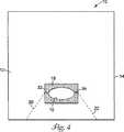
図4を参照すると、第3の実施態様の上面図が例示される。図3の実施態様と比較すると、この図は、引裂き線20、22が同一直線上にある必要はなく、その代わりに互いに対して傾斜角を有してもよいことを示す。傾斜角は、ドレープの上部として使用されるドレープのより大きい部分が、額に隣接する患者の髪と患者の耳とそれに隣接する髪とを完全に覆うように、選択されることが好ましい。たとえば、傾斜角は、2本の引裂き線の間の開先角度として規定され、およそ100度である。穿孔20、22の線が周縁までずっと延びることは必要条件ではないが、そのような実施態様は現在では好適であるとみなされる。
【0022】
使用において、図4に示されるドレープのより大きい上部は、接着剤領域の上部を患者の上まぶたに貼付し、上まぶたを引いて眼の適切な露出を得た後に、患者の額、髪および耳の上に置かれる。ドレープの下部は、接着剤領域の下部を下まぶたに貼付することによって眼から離れた方向へ下まぶたを引くのに使用されるてもよい。
【0023】
シート12は、多くの種類のポリマーフィルム、特にポリオレフィンフィルムから便利に製造される。現在では、静電防止処理されたポリエチレンフィルムを使用することが、好適であるとみなされる。皮膚適合性接着剤18は、アクリレート接着剤から便利に調製される。適切な複合材料の検討は、同譲受人に譲渡されたUlrichに付与された米国再発行特許第24,906号に見ることができる。たとえば、その特許の実施例5として検討されたアクリレート接着剤が適切である。
【0024】
あるいは、用途によっては、シート12は他の材料から製造することができ、たとえば、シート12は、メルトブローウェブまたはスパンボンドウェブを含むがそれに限定されない不織構造物であってもよい。
【0025】
二重スティック接着剤は一般に、両側に塗布された接着剤を備えた接着テープとライナー(たとえば、紙またはポリマーのライナー)とを具備する。パターンコーティングは、印刷型プロセスまたはダイコーティングを含んでもよい。トランスファー接着剤は一般に、第1のライナー(たとえば、接着剤次第で、シリコーン剥離コーティングを備えたポリエチレンフィルムライナー32等の紙またはポリマー)に塗布された接着剤を具備し、これは、トランスファー接着剤が使用される前または後に除去される。第2のライナー(たとえば、接着剤によって、シリコーン剥離コーティングを備えたポリエチレンフィルムライナー32等の紙またはポリマー)が、第1のライナーが除去される前または後のいずれかに接着剤にラミネートされてもよい。
【0026】
ドレープは、不定の長さのシート材料から容易に調製され、これがドレープの主要部分を形成する。たとえば、第1の転換ステーションで、不定の長さのシート材料は、上述のように接着された剥離ライナーを備えたトランスファー接着剤または二重スティックパッチをこれに接着していてもよい。第2の転換ステーションで、開口部およびミシン目が回転ダイカッターでシートおよびトランスファー接着剤または二重スティックパッチに切削される。最後に、回転ナイフカッターが、不定の長さのシートから仕上げドレープを切り離し、これは、次いで、顧客用に、折られ、包装され、殺菌されるように準備される。
【0027】
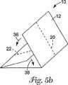
特に、図1のドレープの実施態様は、医療従事者が1回引いてドレープを2つの類似半体に便利に分割することができ、一方、ドレープは、医療従事者の必要にふさわしければ折られたままであるように、折ることができる。次に図5aを参照すると、完成したドレープ10が2つのS字折りで折られ、そのため2本の同一直線上のミシン目が依然として同一平面上にある。第2の折りは、図5bの方向矢印36、38によって示されるようにされる。最後に、第3の折りは、図5cに示されるようにされ、そのため、穿孔20、22の線のすべての折られたセグメントが最終折りの頂点にある。これによって、医療従事者は、たとえばドレープ10を隅40、42でつかみ、1回引いてドレープを類似半体に分割することができる。
【0028】
図6〜13は、100で示される本発明の眼科手術ドレープのさらに別の実施態様を示す。ドレープ100は、図3に示されるドレープ10に類似する。好ましくは、ドレープ100は略矩形の輪郭を有し、略楕円または細長い眼開口102と、引裂き線104(たとえば、穿孔か、またはドレープに刻み目を入れることによって形成されてもよい)と、眼開口を囲繞する略矩形領域にドレープの一方の面上に接着剤領域とを含む。剥離ライナー106が接着剤領域を覆う。引裂き線104は、好ましくは、楕円眼開口102の長軸によって規定される方向に延びる。好適な引裂き線104は、ドレープを2つの等しいセクションに分割するのではなく、むしろ中心線を外れている。ドレープ100のより小さいセクション108は「短い側」と称され、ドレープのより大きいセクション110は「長い側」と称される。
【0029】
図6〜13に例示されるように、医療従事者が、予め広げることなくドレープ100を2つの部分に分けることができるように、ドレープ100は折られる。図6〜13に例示される好適な折りプロセスによって、接着剤領域および剥離ライナー106が外部に維持され、すなわちドレープ100は、剥離ライナー106のいずれの部分を覆うようには折られない。好適な折りプロセスは下記の通りである。
【0030】
A.ドレープ100はまず、図7に例示されるように、引裂き線104に平行な長い側110を通って走る第1折り目FL−1に沿って折られる。上折り畳み領域112は、眼開口102を完全に覆わなければならない。矩形ドレープ100のより長い寸法「L」は約27.5cmであり、引裂き線104は第1の縁114から約7cm間隔をおかれるならば、折り目FL−1はドレープ100の第1の縁112から約5cm間隔をおかれる。この折りステップの結果は図8に示される。
【0031】
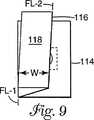
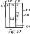
B.ドレープは次いで、図9、10に例示されるように、第1の折りと組み合わせて「S」または「Z」折りを形成するように、引裂き線104に平行な方向に第2折り目FL−2に沿って折られる。上折り畳み領域118の折り縁116は、眼開口102の領域の半分よりも少なく覆わなければならず、引裂き線104を覆ってはならない。たとえば、上折り畳み領域116の幅「W」が約5.8cmであるならば、折り縁116は引裂き線104から約1.2cm間隔をおかれる。眼開口102の高さ(すなわち、開口の短い寸法)が約3.8cmであれば、この例は結果として、眼開口102の約0.7cmが上折り畳み領域118によって覆われるかまたは重ね合わせられる。この重ね合わせ領域が1cm未満に保たれることが好適である。あるいは、2本以上の平行な第2折り目が設けられてもよく、またはドレープのこの部分は「ロール」折りされてもよい。
【0032】
C.ドレープは次いで、図11に例示されるように、引裂き線104および折り目FL−1、FL−2に対して略垂直な折り目FL−3、FL−4に沿って、3つに折られる。この折りステップの結果は図12に示される。
【0033】
D.ドレープは次いで、引裂き線104に対して垂直な方向に眼開口102を二等分する折り目FL−5に沿って、半分に折られる。このステップの結果は図13に示される。図13に示される折られたドレープは、ドレープを広げることなく引裂き線104に沿って分離することができる。
【0034】
上記ステップA〜Dで述べられた好適な折りプロセスは、下記を理解すると、図4に示されたドレープに対して容易に使用することができる。傾斜した引裂き線20、22の方向は、このプロセスでは使用されない。その代わり、引裂き線20、22に交差するドレープの縁に平行な方向に眼開口を二等分する陰線を使用する。これを理解すると、傾斜した引裂き線20、22を備えたドレープも、ドレープを広げることなく引裂き線に沿って分離することができるように折ることができる。
【0035】
図14は本発明の別の実施態様を例示し、その中でドレープ200は、略楕円形状の開口部204の両端から延びる引裂き線202(たとえば、穿孔)を含む。接着剤領域206、208が、開口部204および引裂き線に隣接するドレープ200の一方の面に沿って、設けられる。
【0036】
図15は本発明のドレープ210を例示し、その中で傾斜した引裂き線212は、略楕円形状の開口部214の端からドレープ210の周縁へ途中まで延びる。
【0037】
図16は、図14のドレープ200にいくつかの点で類似したドレープ220を例示するが、接着剤領域222が引裂き線224に沿ってドレープ220の周囲縁から内側へ中央接着剤領域226へ途中まで延びることが異なる。
【0038】
図17は、図14のドレープ200にいくつかの点で類似したドレープ230を例示するが、開口部232を囲繞する中央接着剤領域がこのドレープでは設けられていないことが異なる。
【0039】
図18はドレープ240を例示し、その中で引裂き線242は、略楕円形状の開口部244の両端からドレープの縁へ途中まで延びる。開口部244を囲繞する接着剤領域246が設けられる。
【0040】
図19は、図14のドレープ100に多くの点で類似したドレープ250を例示するが、引裂き線260に沿った接着剤領域252、254、256、258が非接着剤領域によって分離されることが異なる。
【0041】
図20は、2つの略楕円形状の開口部272、274と、傾斜した引裂き線276、278と、側方向に延びる引裂き線280、282と、開口部272、274を囲繞する接着剤領域284、286とを含むドレープ270を例示する。
【0042】
図21は、ドレープ270に多くの点で類似したドレープ290を例示するが、傾斜した引裂き線が開口部294、296の間に延びる引裂き線292に取って替わられることが異なる。
【0043】
使用によっては、開口部が楕円形、円形、矩形またはその使用に適切な他のいずれの形状であってもよいことが企図される。図20、21に示されるように、2つ以上の開口部があってもよい。
【0044】
請求の範囲に規定された本発明の範囲から逸脱することなく、上記の構造物および方法に様々な変更を行うことが可能であるため、上記の説明に含まれるすべての事項または添付の図面に示されるすべての事項は、例示的なものであると解釈され、限定的な意味で解釈されるべきではないことが意図される。
【図面の簡単な説明】
本発明は図面を参照してさらに説明され、図面において対応する参照符号は数枚の図面にわたって対応する部品を示す。
【図1】 本発明の第1の実施態様による眼科ドレープの上面図である。
【図2a】 セクション線2−2に沿って取られた図1のドレープの部分断面図である。
【図2b】 別の配列の図2aの部分断面図である。
【図3】 第2の実施態様の上面図である。
【図4】 第3の実施態様の上面図である。
【図5a】 図1のドレープの最終折りに沿った段階である。
【図5b】 図1のドレープの最終折りに沿った段階である。
【図5c】 図1のドレープの最終折りに沿った段階である。
【図6】 ドレープを折るための方法の別の好適な実施態様を例示する。
【図7】 ドレープを折るための方法の別の好適な実施態様を例示する。
【図8】 ドレープを折るための方法の別の好適な実施態様を例示する。
【図9】 ドレープを折るための方法の別の好適な実施態様を例示する。
【図10】 ドレープを折るための方法の別の好適な実施態様を例示する。
【図11】 ドレープを折るための方法の別の好適な実施態様を例示する。
【図12】 ドレープを折るための方法の別の好適な実施態様を例示する。
【図13】 ドレープを折るための方法の別の好適な実施態様を例示する。
【図14】 本発明のドレープのさなる好適な実施態様を例示する。
【図15】 本発明のドレープのさなる好適な実施態様を例示する。
【図16】 本発明のドレープのさなる好適な実施態様を例示する。
【図17】 本発明のドレープのさなる好適な実施態様を例示する。
【図18】 本発明のドレープのさなる好適な実施態様を例示する。
【図19】 本発明のドレープのさなる好適な実施態様を例示する。
【図20】 本発明のドレープのさなる好適な実施態様を例示する。
【図21】 本発明のドレープのさなる好適な実施熊様を例示する。[0001]
The present invention relates primarily to surgical drapes and methods for applying such drapes, and more particularly to ophthalmic drapes having an adhesive portion that can adhere to the skin adjacent to the eye and methods for applying such drapes. It is also contemplated that this drape can be used for limb surgery, “otolaryngology” and “small” surgery, tracheostomy or thyroidectomy, and thoracic surgery, among others.
[0002]
BACKGROUND OF THE INVENTION To perform eye surgery, a surgical drape is applied to the patient to isolate the eyelashes and eyelids from the surgical site to improve eye exposure and provide a sterile drape surface to reduce the likelihood of infection. It is often desirable. For example, in refractory surgery, drapes are first used to pull the eyelids and eyelashes away from the eye so that they do not interfere with surgical instruments such as microkeratomes.
[0003]
One product used for this purpose is the Model 1020 Ophthalmic Drape sold by Minnesota Mining and Manufacturing, Inc., St. Paul, Minnesota. The drape includes a sheet of material having a substantially round opening in the approximate center. The area of skin compatible adhesive contacts a portion of one side of the sheet adjacent to this opening. With this adhesive, the drape can be glued around the patient's eyes, and the rest of the sheet hangs down from the patient's head, hair and face, providing a sterile surface over those areas.
[0004]
The eye is a delicate structure, the eyelid is very flexible, and the size and shape varies from person to person, making it difficult. In actual surgery, health care workers may find it inconvenient to adapt the edge of the opening to the edge of a particular patient's eyelid. When this happens, one procedure known to medical personnel is to cut the drape partially or completely into two sections, generally but not always, before applying the drape to the patient. This can relieve tension in the stretch region, prevent the adhesive region from clumping, and make the edge of the opening more closely match the edge of the patient's eye. In addition, cutting the drape before applying can cause many surgeons to make it easier for one person to apply the drape to the upper eyelid without gluing the bottom of the adhesive field to the lower eyelid until ready. This is a suitable business.
[0005]
It will be appreciated that this procedure is not without drawbacks. Such cutting requires the presence of sterile scissors or the like. Also, it is inconvenient to cut properly while trying to maintain the sterility of the drape.
[0006]
DISCLOSURE OF THE INVENTION The present invention relates to an ophthalmic surgical drape that allows one person to easily adapt the drape to both eyelids without additional tools, and a method for draping the eye for ophthalmic surgery. The present invention provides a method for applying an ophthalmic drape so that it can be easily adhered to both the top and bottom of the eye without the need to use a separate instrument to cut or adjust. By providing, the above-mentioned problems are solved. This is accomplished by providing at least two tear lines in the sheet that forms the drape, at least in the region adjacent to the opening that is accessible to the eye. The health care professional then glues the edge of the opening to one of the patient's eyelids, breaking as much or as little of the tear line as possible, creating the necessary slack, and the rest of the opening edge Is precisely aligned with the other eyelid of the patient. If such action makes it easier for the health care worker to place the drape, the drape may be completely divided into two similar halves.
[0007]
The present invention provides a method of applying an ophthalmic surgical drape to both the upper and lower eyelids of a patient. A surgical drape is provided that includes a sheet having a periphery, an opening spaced from the periphery, and at least two tear lines in the sheet that extend substantially from the opening to the periphery. The drape has a region of skin-compatible adhesive adjacent to the opening and each tear line extends across to divide this region into at least two parts. The sheet is torn partially or completely along at least one tear line. Depending on the size and shape of the particular patient's eye, some tearing may be necessary, or it may be most convenient to tear the drape completely in two parts. In any case, the health care professional can achieve this conveniently without the help of others. The method also includes adhering a portion of the area of skin compatible adhesive to one eyelid (eg, the upper eyelid). The edge of the opening is preferably curved so as to approximate the shape of the eyelid edge of an open person's eye. Finally, the method then includes the step of gluing the other part of the area of skin compatible adhesive to the other eyelid (eg the lower eyelid).
[0008]
In a preferred embodiment, the tear line extends substantially completely from the opening to the periphery, which is the maximum for the healthcare professional if substantial modifications are required to fit a patient. Provide flexibility. Further, it was found that it is particularly convenient to prepare a symmetric edge that is curved at the opening, and the point where the perforation extends from the opening is on the point facing the radial direction on the edge.
[0009]
The tear line may be a perforated or scored line of the sheet of material, or the sheet of material can be easily teared as desired to accurately advance the desired tear. It may be weakened by heat or some other physical process. As used herein, a “tear line” refers to a line along which tearing a material by hand is directed by any of these mechanisms.
[0010]
As used herein, “elliptical shape” refers primarily to elliptical and oval shapes, as well as elongated curved openings.
[0011]
In some preferred embodiments, it is convenient to protect the area of skin compatible adhesive by adhering a release liner to this area. The release liner protects the adhesive during shipping and handling, but is peeled off before being applied to the patient by the drape user. For convenience during application, at least one edge of the release liner extends beyond the edge of the adhesive area to provide a tab suitable for grasping.
[0012]
Also, in a preferred embodiment, the drape is provided in a folded state and folded so that tearing can be achieved to split the drape into two sections, such as two similar halves, before the drape is expanded. .
[0013]
With this in mind, the present invention can therefore be viewed separately. Ophthalmic surgical drape comprising a sheet having a peripheral edge, an opening spaced from the peripheral edge of the sheet, and a tear line in the sheet extending in the opposite direction from the opening to the peripheral edge of the sheet and dividing the sheet into two parts Can be thought of as There are two parts to the collinear tear line on both sides of the opening, but this embodiment is designed to be split before spreading, so one in two halves It is convenient to think of a book tear line. The ophthalmic surgical drape has an area of skin-compatible adhesive adjacent to the opening, and the sewing machine is divided into two adhesive sections, one for each of the two sections of the sheet. The eyes extend across. The sheet is folded in the direction perpendicular to the tear line and also along the tear line, so that the sheet can be spread over the tear line and the sheet against all folds perpendicular to the tear line. The two parts of the sheet can be separated from each other by grasping the two parts of the sheet before spreading and tearing the sheet along the tear line.
[0014]
Yet another embodiment of the ophthalmic surgical drape of the present invention generally comprises a sheet having a peripheral edge and an opening spaced from the peripheral edge of the sheet, the opening having both sides. In this embodiment, the two tear lines extend along the sheet at an angle of inclination with respect to each other substantially from both sides of the opening to substantially the periphery of the sheet, dividing the sheet into two parts. The drape has an area of skin-compatible adhesive adjacent to the opening, and the tear line crosses across the adhesive line to divide this area into two adhesive parts, one for each of the two parts of the sheet. Extend.
[0015]
One feature of the oblique tear line angle embodiment is that the two parts of the sheet are of different dimensions. Most preferably, the larger portion constitutes the upper portion that is placed on the patient's head and hair, and the adhesive portion is applied to the upper eyelid. The tilt angle (eg, the bevel angle between two tear lines of approximately 100 degrees) is preferably selected so that a larger portion of the sheet completely covers the patient's forehead and the hair adjacent to the ear. . This reduces the chance that the surgeon's gloves or instrument will touch the patient's hair between adjacent drapes. The surgeon typically works on the patient's head from above, and the patient's body generally extends away from the surgeon so that the larger portion of the drape in this embodiment also faces the surgeon.
[0016]
Also, preferably, the oblique tear line extends from both edges of the adhesive region substantially adjacent to the long axis end of the elliptical opening, rather than directly from the long axis end of the opening. In other words, the oblique tear line is separated from the elliptical opening by the adhesive region. A relatively short tear line is provided along the adhesive region in the same direction as the major axis of the opening between the oblique tear line and the opening.
[0017]
Detailed Description of the Preferred Embodiment Referring to FIG. 1, a top view of an ophthalmic
[0018]
Referring to FIG. 2a, a partial cross-sectional view of the drape of FIG. 1 taken along section line 2-2 is illustrated. The
[0019]
Referring to FIG. 2b, a second partial cross-sectional view of the drape of FIG. 1 taken along section line 2-2 is illustrated, with the skin compatible
[0020]
Referring to FIG. 3, a top view of the second embodiment is illustrated. Compared to the embodiment of FIG. 1, this figure shows that the
[0021]
Referring to FIG. 4, a top view of the third embodiment is illustrated. Compared to the embodiment of FIG. 3, this figure shows that the tear lines 20, 22 need not be collinear, but instead may have an angle of inclination with respect to each other. The angle of inclination is preferably selected so that the larger portion of the drape used as the top of the drape completely covers the patient's hair adjacent to the forehead, the patient's ear and the adjacent hair. For example, the tilt angle is defined as the groove angle between two tear lines and is approximately 100 degrees. Although it is not a requirement that the
[0022]
In use, the larger top of the drape shown in FIG. 4 applies the top of the adhesive area to the patient's upper eyelid and pulls the upper eyelid to obtain proper exposure of the eye before the patient's forehead, hair and Placed on the ear. The lower part of the drape may be used to pull the lower eyelid away from the eye by applying the lower part of the adhesive area to the lower eyelid.
[0023]
[0024]
Alternatively, depending on the application, the
[0025]
Dual stick adhesives generally comprise an adhesive tape with an adhesive applied on both sides and a liner (eg, a paper or polymer liner). Pattern coating may include a printing process or die coating. The transfer adhesive generally comprises an adhesive applied to a first liner (eg, paper or polymer such as
[0026]
The drape is easily prepared from an indefinite length of sheet material, which forms the main part of the drape. For example, at a first conversion station, an indefinite length of sheet material may have a transfer adhesive or double stick patch with a release liner adhered as described above adhered thereto. At the second conversion station, the openings and perforations are cut with a rotating die cutter into sheets and transfer adhesive or double stick patches. Finally, a rotary knife cutter cuts the finished drape from the indefinite length sheet, which is then ready to be folded, packaged and sterilized for the customer.
[0027]
In particular, the drape embodiment of FIG. 1 can be conveniently pulled by a medical practitioner to divide the drape into two similar halves, while the drape is folded if appropriate to the needs of the medical practitioner. Can be folded as it is. Referring now to FIG. 5a, the completed
[0028]
FIGS. 6-13 illustrate yet another embodiment of the ophthalmic surgical drape of the present invention, indicated at 100. The
[0029]
As illustrated in FIGS. 6-13, the
[0030]
A. The
[0031]
B. The drape then has a second fold FL-2 in a direction parallel to the
[0032]
C. The drape is then folded in three along fold lines FL-3, FL-4 that are generally perpendicular to tear
[0033]
D. The drape is then folded in half along a fold FL-5 that bisects the eye opening 102 in a direction perpendicular to the
[0034]
The preferred folding process described in steps AD above can be readily used for the drape shown in FIG. The direction of the
[0035]
FIG. 14 illustrates another embodiment of the present invention, in which drape 200 includes tear lines 202 (eg, perforations) that extend from opposite ends of a generally
[0036]
FIG. 15 illustrates a
[0037]
FIG. 16 illustrates a
[0038]
FIG. 17 illustrates a
[0039]
FIG. 18 illustrates a
[0040]
FIG. 19 illustrates a
[0041]
FIG. 20 illustrates two generally
[0042]
FIG. 21 illustrates a
[0043]
Depending on the use, it is contemplated that the opening may be oval, circular, rectangular or any other shape suitable for its use. There may be more than one opening as shown in FIGS.
[0044]
Various modifications can be made to the structures and methods described above without departing from the scope of the invention as defined in the claims, therefore all matters contained in the above description or attached drawings are included. It is intended that all matter shown is to be construed as illustrative and not in a limiting sense.
[Brief description of the drawings]
The invention will be further described with reference to the drawings, wherein like reference numerals designate corresponding parts throughout the several views.
FIG. 1 is a top view of an ophthalmic drape according to a first embodiment of the present invention.
2a is a partial cross-sectional view of the drape of FIG. 1 taken along section line 2-2.
2b is a partial cross-sectional view of FIG. 2a in another arrangement.
FIG. 3 is a top view of the second embodiment.
FIG. 4 is a top view of the third embodiment.
5a is a stage along the final fold of the drape of FIG.
FIG. 5b is a step along the final fold of the drape of FIG.
FIG. 5c is a step along the final fold of the drape of FIG.
FIG. 6 illustrates another preferred embodiment of a method for folding a drape.
FIG. 7 illustrates another preferred embodiment of a method for folding a drape.
FIG. 8 illustrates another preferred embodiment of a method for folding a drape.
FIG. 9 illustrates another preferred embodiment of a method for folding a drape.
FIG. 10 illustrates another preferred embodiment of a method for folding a drape.
FIG. 11 illustrates another preferred embodiment of a method for folding a drape.
FIG. 12 illustrates another preferred embodiment of a method for folding a drape.
FIG. 13 illustrates another preferred embodiment of a method for folding a drape.
FIG. 14 illustrates another preferred embodiment of the drape of the present invention.
FIG. 15 illustrates another preferred embodiment of the drape of the present invention.
FIG. 16 illustrates another preferred embodiment of the drape of the present invention.
FIG. 17 illustrates another preferred embodiment of the drape of the present invention.
FIG. 18 illustrates another preferred embodiment of the drape of the present invention.
FIG. 19 illustrates another preferred embodiment of the drape of the present invention.
FIG. 20 illustrates another preferred embodiment of the drape of the present invention.
FIG. 21 illustrates a further preferred bear embodiment of the drape of the present invention.
Claims (2)
Translated fromJapaneseシート(12)であって、周縁(14)と、対向辺を有して該周縁から離間した開口部(16)と、該開口部の該対向辺と該周縁との間で、互いに傾斜角を成して延びて該シートを互いに寸法の異なる2つの部分に分割する2本の引裂き線(20、22)とを有するシートと、
前記開口部に隣接する皮膚適合性接着剤の領域(18)であって、該領域を、前記シートの前記2つの部分の各々に1つずつの、2つの接着剤部分に分割するように、前記2本の引裂き線が横切って延びる皮膚適合性接着剤の領域とを具備し、
前記シートの前記開口部は、前記シートの中心から前記周縁の一部分に向かってずれて配置され、前記2本の引裂き線は、前記開口部の前記対向辺と前記周縁の該一部分との間に延びている、
眼科手術ドレープ。In ophthalmic surgery drape (10),
The sheet (12), the peripheral edge (14), the opening (16) having an opposing side and spaced from the peripheral edge, and the inclination angle between the opposing side and the peripheral edge of the opening A sheet having two tear lines (20, 22) extending in the direction of dividing the sheet into two parts of different dimensions;
A skin compatible adhesive region (18) adjacent to the opening, dividing the region into two adhesive portions, one for each of the two portions of the sheet;; and a region of the skin-compatible adhesive extending across said two tear lines,
The opening of the sheet is arranged to be shifted from the center of the sheet toward a part of the peripheral edge, and the two tear lines are between the opposite side of the opening and the part of the peripheral edge. Extending,
Ophthalmic surgery drape.
(a)シート(12)であって、互いに反対側の第1および第2の端縁と、互いに反対側の第1および第2の側縁と、それら端縁および側縁から離間した開口部(16)と、該開口部と該第1の端縁との間で、互いに傾斜角を成して延びて該シートを互いに寸法の異なる2つの部分に分割する2本の引裂き線(22、24)とを有し、該開口部が、該第1の端縁に向かって中心からずれているが該第1および第2の側縁に対しては中心に配置されているシートと、該開口部に隣接する皮膚適合性接着剤の領域(18)と、を具備する眼科手術ドレープ(10)を用意するステップと、
(b)前記開口部と前記2本の引裂き線の少なくとも一部とを覆う第1折り畳み領域を形成するように、前記第1および第2の端縁に平行な第1折り目に沿って前記眼科手術ドレープを折るステップと、
(c)前記2本の引裂き線の全体を露出させるように、前記第1折り目に平行な第2折り目に沿って、前記ドレープの前記第1折り畳み領域を折るステップと、
(d)前記第1および第2折り目に垂直な第3および第4折り目に沿って、前記ドレープを3つに折るステップと、
(e)前記第3および第4折り目に平行な第5折り目であって前記開口部を二等分する第5折り目に沿って、前記ドレープを折るステップと、
(f)前記ドレープが前記皮膚適合性接着剤の領域を覆わないように、前記ステップ(b)〜(e)を通じて該皮膚適合性接着剤の領域を外向き方向に保つステップと、
を具備する方法。In the method of folding the ophthalmic surgical drape (10),
(A) The sheet (12), the first and second end edges opposite to each other, the first and second side edges opposite to each other, and an opening spaced from the end edges and side edges (16) and two tear lines (22,) extending between the opening and the first edge at an angle of inclination to divide the sheet into two parts having different dimensions. 24), and the opening is offset from the center toward the first edge but centered with respect to the first and second side edges, and Providing an ophthalmic surgical drape (10) comprising: a skin compatible adhesive region (18) adjacent to the opening;
(B) the ophthalmologic along a first fold parallel to the first and second end edges so as to form a first folding region covering the opening and at least a portion of the two tear lines. Folding the surgical drape;
(C) folding the first fold region of the drape along a second fold parallel to the first fold so as to expose the entire two tear lines;
(D) folding the drape in three along third and fourth folds perpendicular to the first and second folds;
(E) folding the drape along a fifth fold that is parallel to the third and fourth folds and that bisects the opening;
(F) maintaining the skin-compatible adhesive region in an outward direction through steps (b)-(e) so that the drape does not cover the skin-compatible adhesive region;
A method comprising:
Applications Claiming Priority (5)
| Application Number | Priority Date | Filing Date | Title |
|---|---|---|---|
| US94182197A | 1997-10-01 | 1997-10-01 | |
| US08/941,821 | 1997-10-01 | ||
| US1615498A | 1998-01-30 | 1998-01-30 | |
| US09/016,154 | 1998-01-30 | ||
| PCT/US1998/020612WO1999016377A1 (en) | 1997-10-01 | 1998-09-29 | Ophthalmic drape with tear line and method |
Related Child Applications (1)
| Application Number | Title | Priority Date | Filing Date |
|---|---|---|---|
| JP2007335292ADivisionJP4662972B2 (en) | 1997-10-01 | 2007-12-26 | Ophthalmic drape with tear line |
Publications (3)
| Publication Number | Publication Date |
|---|---|
| JP2001517532A JP2001517532A (en) | 2001-10-09 |
| JP2001517532A5 JP2001517532A5 (en) | 2006-02-16 |
| JP4463977B2true JP4463977B2 (en) | 2010-05-19 |
Family
ID=26688242
Family Applications (2)
| Application Number | Title | Priority Date | Filing Date |
|---|---|---|---|
| JP2000513521AExpired - Fee RelatedJP4463977B2 (en) | 1997-10-01 | 1998-09-29 | Ophthalmic surgical drape and method of folding an ophthalmic surgical drape |
| JP2007335292AExpired - Fee RelatedJP4662972B2 (en) | 1997-10-01 | 2007-12-26 | Ophthalmic drape with tear line |
Family Applications After (1)
| Application Number | Title | Priority Date | Filing Date |
|---|---|---|---|
| JP2007335292AExpired - Fee RelatedJP4662972B2 (en) | 1997-10-01 | 2007-12-26 | Ophthalmic drape with tear line |
Country Status (7)
| Country | Link |
|---|---|
| US (3) | US6105579A (en) |
| EP (2) | EP1537832B1 (en) |
| JP (2) | JP4463977B2 (en) |
| AU (1) | AU729852B2 (en) |
| CA (1) | CA2303231A1 (en) |
| DE (2) | DE69829301T2 (en) |
| WO (1) | WO1999016377A1 (en) |
Cited By (1)
| Publication number | Priority date | Publication date | Assignee | Title |
|---|---|---|---|---|
| KR20200001486U (en) | 2018-12-26 | 2020-07-06 | 주식회사 디엔 | Drape for ophthalmic surgery |
Families Citing this family (52)
| Publication number | Priority date | Publication date | Assignee | Title |
|---|---|---|---|---|
| AU729852B2 (en)* | 1997-10-01 | 2001-02-08 | Minnesota Mining And Manufacturing Company | Ophthalmic drape with tear line and method |
| US6286511B1 (en)* | 1997-10-01 | 2001-09-11 | 3M Innovative Properties Company | Ophthalmic drape with tear line and method |
| US6382212B1 (en)* | 2000-01-18 | 2002-05-07 | Medtronic, Inc. | Fenestrated surgical drape with in situ features |
| US7114500B2 (en)* | 2001-08-28 | 2006-10-03 | Marctec, Llc | Surgical draping system |
| US20080086792A1 (en)* | 2006-10-13 | 2008-04-17 | Thomas Charles Kuracina | Method and apparatus for diverting sweat, liquid, moisture or the like from an eye |
| US20030188753A1 (en)* | 2002-04-03 | 2003-10-09 | Kimberly-Clark Worldwide, Inc. | Radial angiography drape |
| US6863071B2 (en)* | 2002-07-03 | 2005-03-08 | Medical Concepts Development, Inc. | Refractive surgical drape |
| US6871651B2 (en)* | 2003-07-10 | 2005-03-29 | Ophthalmic surgical drape support | |
| US7275544B2 (en)* | 2003-12-01 | 2007-10-02 | Michael Gil | Covering for an aseptic treatment site |
| US7290547B2 (en)* | 2003-12-01 | 2007-11-06 | Joseph Hare | Covering for an aseptic treatment site |
| US6978785B2 (en)* | 2004-04-12 | 2005-12-27 | Iniversal Vision Biotechnology Co., Ltd. | Eye-surgical holed towel |
| US7621278B2 (en)* | 2004-11-01 | 2009-11-24 | Herminia Mino Sotelo De Kaspar | Eye drape for surgical procedures |
| US6966320B1 (en) | 2004-11-09 | 2005-11-22 | Samentha Baynes | Surgical covering assembly |
| JP4071775B2 (en)* | 2005-02-10 | 2008-04-02 | 株式会社リブドゥコーポレーション | Ophthalmic surgery covering |
| FR2896146B1 (en)* | 2006-01-19 | 2008-03-28 | Vygon Sa | IMPROVEMENTS IN WINDOW OPERATING FIELDS |
| GB0612884D0 (en)* | 2006-06-29 | 2006-08-09 | Smiths Group Plc | Drapes |
| GB0612913D0 (en)* | 2006-06-30 | 2006-08-09 | Finsbury Dev Ltd | Apparatus |
| DE202006014746U1 (en)* | 2006-09-22 | 2006-12-07 | Geuder Ag | Sheet covering body of patient during operation, comprises surgical opening protected by patch with predetermined breaking line |
| US20100107306A1 (en)* | 2006-10-13 | 2010-05-06 | Kuracina Thomas C | Method and apparatus for diverting sweat, liquid, moisture, or the like from an eye |
| US7856984B2 (en)* | 2006-12-21 | 2010-12-28 | Ppc Industries, Inc. | Surgical covering material |
| US20080236598A1 (en)* | 2007-03-30 | 2008-10-02 | Fred Gobel | Drape for open tracheal suctioning |
| FR2918870B1 (en) | 2007-07-16 | 2009-10-09 | Vygon Sa | IMPROVEMENTS IN WINDOW OPERATING FIELDS |
| US20090320852A1 (en)* | 2008-06-27 | 2009-12-31 | Cuevas Brian J | Tracheostomy Tube Butterfly Flange |
| US10271916B2 (en)* | 2008-08-08 | 2019-04-30 | Medline Industries, Inc. | Zip strip draping system and methods of manufacturing same |
| US10039610B2 (en)* | 2008-08-08 | 2018-08-07 | Medline Industries, Inc. | Zip strip draping system and methods of manufacturing same |
| US20100300459A1 (en)* | 2009-05-26 | 2010-12-02 | Lair Anthony C | Drape and method of using same |
| JP5464918B2 (en)* | 2009-06-12 | 2014-04-09 | 株式会社ホギメディカル | Ophthalmic surgery drape |
| US8464722B2 (en)* | 2010-03-04 | 2013-06-18 | Medline Industries, Inc. | Folded telescopic equipment drape and method of folding and using the same |
| EP2552338B1 (en)* | 2010-03-31 | 2021-08-18 | Allegiance Corporation | Surgical drape having tearable sheet |
| US8826912B2 (en) | 2010-06-25 | 2014-09-09 | Vanderbilt University | Surgical drape |
| US9072646B2 (en)* | 2010-12-14 | 2015-07-07 | Allen Medical Systems, Inc. | Lateral surgical platform with rotation |
| US10639118B2 (en)* | 2011-04-06 | 2020-05-05 | Entrotech Life Sciences, Inc. | Surgical incise drapes and methods for their application |
| US9937015B2 (en) | 2011-05-26 | 2018-04-10 | Medline Industries, Inc. | Surgical drape configured for peripherally inserted central catheter procedures |
| US9820751B2 (en) | 2011-05-26 | 2017-11-21 | Medline Industries, Inc. | Surgical drape configured for peripherally inserted central catheter procedures |
| US10188475B2 (en) | 2011-10-13 | 2019-01-29 | Medline Industries, Inc. | Drape for equipment having cylindrical or other non-planar contours |
| US10455872B2 (en) | 2011-10-18 | 2019-10-29 | Medline Industries, Inc. | Disposable medical gown |
| USD821704S1 (en) | 2011-10-18 | 2018-07-03 | Medline Industries, Inc. | Medical gown |
| US8826911B2 (en) | 2011-11-04 | 2014-09-09 | David Power | Barrier protection using linear tear technology |
| US20130263867A1 (en)* | 2012-04-04 | 2013-10-10 | Michael J. Young | Surgical drape |
| FR2990842B1 (en) | 2012-05-25 | 2015-04-24 | Vygon | MODULAR OPERATIVE FIELD, OPERATIVE FIELD ATTACHMENT AND METHOD FOR MANUFACTURING THE SAME |
| JP5903016B2 (en)* | 2012-06-27 | 2016-04-13 | コスメディ製薬株式会社 | Protective release sheet for microneedle patch |
| US11116263B2 (en) | 2013-11-21 | 2021-09-14 | Medline Industries, Inc. | Gown for self-donning while maintaining sterility and methods therefor |
| USD804677S1 (en)* | 2015-09-30 | 2017-12-05 | 3M Innovative Properties Company | Surgical drape with a retraction member |
| USD804678S1 (en)* | 2015-09-30 | 2017-12-05 | 3M Innovative Properties Company | Oval surgical drape with a retraction member |
| USD796685S1 (en)* | 2016-02-08 | 2017-09-05 | Zoiea Ohizep | Surgical drape |
| US10729507B2 (en) | 2017-01-12 | 2020-08-04 | Warsaw Orthopedic, Inc. | Surgical draping system and method for using same |
| WO2018204737A1 (en)* | 2017-05-04 | 2018-11-08 | Nallakrishnan, Ravi | Disposable surgical drape |
| CA3065159A1 (en)* | 2017-06-02 | 2018-12-06 | 3M Innovative Properties Company | Adhesive seal |
| CN107468345A (en)* | 2017-08-30 | 2017-12-15 | 东莞市鸿德医用塑料制品有限公司 | Peel-off sterile cover for surgical instrument protection |
| JP7619045B2 (en)* | 2019-01-11 | 2025-01-22 | Toppanホールディングス株式会社 | Inspection seal unit |
| US20220168060A1 (en)* | 2019-03-21 | 2022-06-02 | Art, Limited | Disposable surgical drape |
| US20220211127A1 (en)* | 2021-01-06 | 2022-07-07 | Trisha Wallace | Personal Protective Gown |
Family Cites Families (61)
| Publication number | Priority date | Publication date | Assignee | Title |
|---|---|---|---|---|
| US24906A (en)* | 1859-07-26 | Simeon goodfellow | ||
| US1044698A (en)* | 1912-02-08 | 1912-11-19 | Reuben Sideman | Reversible breath-shield. |
| US2294593A (en)* | 1940-11-04 | 1942-09-01 | Jessie M Bailey | Head and face protector |
| US2646040A (en) | 1949-12-15 | 1953-07-21 | Austin N Stanton | Bandage |
| IT610737A (en) | 1955-11-18 | 1900-01-01 | ||
| US3030957A (en)* | 1959-03-06 | 1962-04-24 | Frederick J Melges | Disposable obstetrical and/or surgical cover means |
| US3068863A (en)* | 1959-11-19 | 1962-12-18 | Charles L Bowman | Protective devices |
| US3154789A (en)* | 1963-03-25 | 1964-11-03 | Jr Edward Lewis | Disposable examination garment |
| US3410266A (en)* | 1966-06-24 | 1968-11-12 | Johnson & Johnson | Surgical apparel |
| US3565067A (en)* | 1968-09-23 | 1971-02-23 | Mars Mfg Co Inc | Laparotomy sheet with plastic reinforcement |
| US3561439A (en)* | 1968-12-12 | 1971-02-09 | Mars Mfg Co Inc | Laparotomy sheet with plastic center strip having absorbent layer |
| US3667458A (en)* | 1970-03-02 | 1972-06-06 | Kimberly Clark Co | Surgical drape sheet |
| US3766913A (en)* | 1970-04-29 | 1973-10-23 | Kendall & Co | Surgical drape with absorptive region |
| FR2128904A5 (en)* | 1971-03-08 | 1972-10-27 | Ethnor | |
| US3736928A (en)* | 1971-03-15 | 1973-06-05 | Nils O W Rundblad | Collapsible face mask |
| US3835851A (en) | 1972-02-24 | 1974-09-17 | F Villari | Fenestrated drape with retaining means |
| US3750664A (en)* | 1972-04-17 | 1973-08-07 | Kendall & Co | Fenestrated surgical drape |
| US3923052A (en)* | 1972-06-06 | 1975-12-02 | Kendall & Co | Conformable surgical drape |
| US3797484A (en)* | 1972-06-07 | 1974-03-19 | Bard Inc C R | Cystoscopy sheet |
| US3862632A (en)* | 1973-02-23 | 1975-01-28 | Kimberly Clark Co | Surgical drape having integral leggings and method of making |
| US3871369A (en)* | 1973-08-02 | 1975-03-18 | Johnson & Johnson | Self-adhesive surgical apparel and method |
| US3930497A (en)* | 1974-12-05 | 1976-01-06 | Kimberly-Clark Corporation | Surgical drape and system incorporating it |
| US4033341A (en)* | 1976-03-03 | 1977-07-05 | Johnson & Johnson | Surgical drape having improved retaining means |
| US4080963A (en) | 1976-11-15 | 1978-03-28 | The Kendall Company | Fenestrated drape |
| US4089331A (en)* | 1976-12-06 | 1978-05-16 | The Kendall Company | Surgical drape with fenestration liner |
| DE2657520C3 (en)* | 1976-12-18 | 1979-08-23 | Firet B.V., Veenendaal (Niederlande) | Medical drape |
| FR2442047A1 (en)* | 1978-11-22 | 1980-06-20 | Soplaril Sa | Shroud for use in surgical operations - is formed in two halves, both with aperture, and adjustably interconnectable |
| US4275720A (en)* | 1979-08-08 | 1981-06-30 | The Kendall Company | Surgical drape with barrier member |
| US4316456A (en)* | 1980-01-25 | 1982-02-23 | American Hospital Supply Corporation | Surgical drape system |
| US4479492A (en)* | 1980-10-24 | 1984-10-30 | Kimberly-Clark Corporation | Bilateral split surgical drape |
| US4323062A (en)* | 1980-11-28 | 1982-04-06 | The Kendall Company | Surgical drape with retaining device |
| CA1187363A (en)* | 1981-12-07 | 1985-05-21 | Don W. Oliver | Cardiovascular surgical drape |
| US4711236A (en)* | 1982-07-06 | 1987-12-08 | Glassman Jacob A | Surgical drape |
| US4553539A (en) | 1983-09-30 | 1985-11-19 | Surgikos, Inc. | Bilateral fenestrated drape |
| JPS6071205U (en)* | 1983-10-20 | 1985-05-20 | 川本繃帯材料株式会社 | ophthalmic surgery drape |
| EP0166124A3 (en)* | 1984-05-02 | 1987-09-02 | JOHNSON & JOHNSON MEDICAL, INC. | Ophthalmology drape |
| US4627427A (en) | 1984-10-17 | 1986-12-09 | Minnesota Mining And Manufacturing Company | Universal medical cover sheet and process for draping |
| US4896271A (en)* | 1987-08-05 | 1990-01-23 | Tektronix, Inc. | Method and apparatus for measuring jitter in a periodic signal |
| US4739753A (en)* | 1987-08-26 | 1988-04-26 | Brehm, Inc. | Surgical drape support and oxygen delivery system |
| CH673938A5 (en)* | 1987-12-04 | 1990-04-30 | Grounauer Pierre Alain | |
| US4873997A (en)* | 1988-04-25 | 1989-10-17 | Scherer Healthcare Ltd. | Surgical drape |
| US4957120A (en)* | 1988-09-16 | 1990-09-18 | Kimberly-Clark Corporation | Surgical drape with extremity pouch |
| US4869271A (en)* | 1988-12-16 | 1989-09-26 | Kimberly-Clark Corporation | Bi-lateral surgical drape |
| US4966168A (en)* | 1989-01-03 | 1990-10-30 | Glassman Jacob A | Ophthalmic drape with built-in mini-mask |
| DE8904426U1 (en)* | 1989-04-08 | 1989-05-18 | Sengewald Klinikprodukte GmbH, 8201 Rohrdorf | Medical drape |
| DE3931803C1 (en)* | 1989-09-23 | 1990-05-10 | Johnson & Johnson Medical Gmbh, 2000 Norderstedt, De | |
| US5140997A (en)* | 1989-10-04 | 1992-08-25 | Glassman Jacob A | Ophthalmologic surgical drape with breathing means |
| US5140992A (en)* | 1990-07-16 | 1992-08-25 | The United States Of America As Represented By The Administrator Of The National Aeronautics And Space Administration | Passive fetal monitoring sensor |
| US5095918A (en) | 1990-12-07 | 1992-03-17 | Busch Lyndon J | Simplified accessory drape for use by an anesthesia provider and method of use |
| US5109873A (en)* | 1991-07-19 | 1992-05-05 | Scherer Healthcare Ltd. | Surgical drape |
| DK0612232T3 (en) | 1991-11-06 | 1999-11-08 | Bioderm Inc | Closing wound dressing and applicator |
| US5140996A (en)* | 1991-12-20 | 1992-08-25 | Kimberly-Clark Corporation | Central venous catheter patient cover |
| US5267952A (en) | 1991-12-24 | 1993-12-07 | Novamedix, Ltd. | Bandage with transverse slits |
| US5345946A (en) | 1993-04-23 | 1994-09-13 | Johnson & Johnson Medical, Inc. | Multi-element surgical drape with sealable surgical run-off pouches |
| CA2105347A1 (en)* | 1993-04-29 | 1994-10-30 | Gwendolyn Elizabeth Simpson | Modified lithotomy/pelviscopy surgical drape |
| US5647376A (en) | 1995-06-07 | 1997-07-15 | Allegiance Corporation | Surgical drape with elasticized cuff having fenestration and slit |
| US5820578A (en) | 1996-02-05 | 1998-10-13 | Johansen; Christen | Bandage |
| US5975082A (en)* | 1997-03-10 | 1999-11-02 | Kimberly-Clark Worldwide, Inc. | Tear-away surgical drape |
| US5871014A (en) | 1997-03-20 | 1999-02-16 | Allegiance Corporation | Surgical shoulder drape |
| AU729852B2 (en) | 1997-10-01 | 2001-02-08 | Minnesota Mining And Manufacturing Company | Ophthalmic drape with tear line and method |
| US6286511B1 (en)* | 1997-10-01 | 2001-09-11 | 3M Innovative Properties Company | Ophthalmic drape with tear line and method |
- 1998
- 1998-09-29AUAU96769/98Apatent/AU729852B2/ennot_activeCeased
- 1998-09-29DEDE69829301Tpatent/DE69829301T2/ennot_activeExpired - Lifetime
- 1998-09-29WOPCT/US1998/020612patent/WO1999016377A1/enactiveIP Right Grant
- 1998-09-29JPJP2000513521Apatent/JP4463977B2/ennot_activeExpired - Fee Related
- 1998-09-29USUS09/162,684patent/US6105579A/ennot_activeExpired - Lifetime
- 1998-09-29DEDE69841978Tpatent/DE69841978D1/ennot_activeExpired - Lifetime
- 1998-09-29CACA002303231Apatent/CA2303231A1/ennot_activeAbandoned
- 1998-09-29EPEP05004958Apatent/EP1537832B1/ennot_activeExpired - Lifetime
- 1998-09-29EPEP98950823Apatent/EP1018969B1/ennot_activeExpired - Lifetime
- 2001
- 2001-08-02USUS09/922,402patent/US6405730B2/ennot_activeExpired - Fee Related
- 2002
- 2002-04-11USUS10/122,486patent/US20020108615A1/ennot_activeAbandoned
- 2007
- 2007-12-26JPJP2007335292Apatent/JP4662972B2/ennot_activeExpired - Fee Related
Cited By (1)
| Publication number | Priority date | Publication date | Assignee | Title |
|---|---|---|---|---|
| KR20200001486U (en) | 2018-12-26 | 2020-07-06 | 주식회사 디엔 | Drape for ophthalmic surgery |
Also Published As
| Publication number | Publication date |
|---|---|
| JP2008086823A (en) | 2008-04-17 |
| EP1537832B1 (en) | 2010-10-27 |
| US6105579A (en) | 2000-08-22 |
| JP4662972B2 (en) | 2011-03-30 |
| DE69841978D1 (en) | 2010-12-09 |
| CA2303231A1 (en) | 1999-04-08 |
| DE69829301D1 (en) | 2005-04-14 |
| DE69829301T2 (en) | 2006-04-13 |
| EP1537832A1 (en) | 2005-06-08 |
| JP2001517532A (en) | 2001-10-09 |
| EP1018969B1 (en) | 2005-03-09 |
| EP1018969A1 (en) | 2000-07-19 |
| WO1999016377A1 (en) | 1999-04-08 |
| AU729852B2 (en) | 2001-02-08 |
| US20020000232A1 (en) | 2002-01-03 |
| US20020108615A1 (en) | 2002-08-15 |
| AU9676998A (en) | 1999-04-23 |
| US6405730B2 (en) | 2002-06-18 |
Similar Documents
| Publication | Publication Date | Title |
|---|---|---|
| JP4463977B2 (en) | Ophthalmic surgical drape and method of folding an ophthalmic surgical drape | |
| US6286511B1 (en) | Ophthalmic drape with tear line and method | |
| US4041942A (en) | Surgical drape | |
| US4531521A (en) | Skin closure means | |
| JP2956943B2 (en) | Surgical eye patch | |
| CA1061211A (en) | Surgical drape | |
| US6863071B2 (en) | Refractive surgical drape | |
| JPS6157021B2 (en) | ||
| US20180318027A1 (en) | Disposable surgical drape | |
| US20220168060A1 (en) | Disposable surgical drape | |
| US3923052A (en) | Conformable surgical drape | |
| US20160166322A1 (en) | Incise drape for surgical applications and method of positioning the drape over a patient | |
| EP1018968B1 (en) | Ophthalmic drape and methods | |
| US20130263867A1 (en) | Surgical drape | |
| JPH03264058A (en) | Two layer split structure with open window | |
| JPS6128567Y2 (en) | ||
| JP2023545675A (en) | surgical drape | |
| CN217510594U (en) | Disposable operation drape | |
| JPH03264057A (en) | Split structure |
Legal Events
| Date | Code | Title | Description |
|---|---|---|---|
| A521 | Request for written amendment filed | Free format text:JAPANESE INTERMEDIATE CODE: A523 Effective date:20050929 | |
| A621 | Written request for application examination | Free format text:JAPANESE INTERMEDIATE CODE: A621 Effective date:20050929 | |
| A131 | Notification of reasons for refusal | Free format text:JAPANESE INTERMEDIATE CODE: A131 Effective date:20070626 | |
| A601 | Written request for extension of time | Free format text:JAPANESE INTERMEDIATE CODE: A601 Effective date:20070925 | |
| A602 | Written permission of extension of time | Free format text:JAPANESE INTERMEDIATE CODE: A602 Effective date:20071002 | |
| A521 | Request for written amendment filed | Free format text:JAPANESE INTERMEDIATE CODE: A523 Effective date:20071226 | |
| A131 | Notification of reasons for refusal | Free format text:JAPANESE INTERMEDIATE CODE: A131 Effective date:20080603 | |
| A601 | Written request for extension of time | Free format text:JAPANESE INTERMEDIATE CODE: A601 Effective date:20080902 | |
| A602 | Written permission of extension of time | Free format text:JAPANESE INTERMEDIATE CODE: A602 Effective date:20080909 | |
| A521 | Request for written amendment filed | Free format text:JAPANESE INTERMEDIATE CODE: A523 Effective date:20081203 | |
| A02 | Decision of refusal | Free format text:JAPANESE INTERMEDIATE CODE: A02 Effective date:20090623 | |
| A521 | Request for written amendment filed | Free format text:JAPANESE INTERMEDIATE CODE: A523 Effective date:20091023 | |
| A911 | Transfer to examiner for re-examination before appeal (zenchi) | Free format text:JAPANESE INTERMEDIATE CODE: A911 Effective date:20091209 | |
| TRDD | Decision of grant or rejection written | ||
| A01 | Written decision to grant a patent or to grant a registration (utility model) | Free format text:JAPANESE INTERMEDIATE CODE: A01 Effective date:20100119 | |
| A01 | Written decision to grant a patent or to grant a registration (utility model) | Free format text:JAPANESE INTERMEDIATE CODE: A01 | |
| A61 | First payment of annual fees (during grant procedure) | Free format text:JAPANESE INTERMEDIATE CODE: A61 Effective date:20100218 | |
| FPAY | Renewal fee payment (event date is renewal date of database) | Free format text:PAYMENT UNTIL: 20130226 Year of fee payment:3 | |
| R150 | Certificate of patent or registration of utility model | Free format text:JAPANESE INTERMEDIATE CODE: R150 | |
| LAPS | Cancellation because of no payment of annual fees |