JP4463960B2 - X-ray CT system, operation console, control method therefor, and storage medium - Google Patents
X-ray CT system, operation console, control method therefor, and storage mediumDownload PDFInfo
- Publication number
- JP4463960B2 JP4463960B2JP2000296914AJP2000296914AJP4463960B2JP 4463960 B2JP4463960 B2JP 4463960B2JP 2000296914 AJP2000296914 AJP 2000296914AJP 2000296914 AJP2000296914 AJP 2000296914AJP 4463960 B2JP4463960 B2JP 4463960B2
- Authority
- JP
- Japan
- Prior art keywords
- subject
- scan position
- ray
- scan
- current value
- Prior art date
- Legal status (The legal status is an assumption and is not a legal conclusion. Google has not performed a legal analysis and makes no representation as to the accuracy of the status listed.)
- Expired - Fee Related
Links
- 238000000034methodMethods0.000titleclaimsdescription22
- 238000004364calculation methodMethods0.000claimsdescription14
- 238000003384imaging methodMethods0.000claimsdescription14
- 230000008859changeEffects0.000claimsdescription10
- 230000008569processEffects0.000claimsdescription7
- 230000001678irradiating effectEffects0.000claims4
- 239000011295pitchSubstances0.000description35
- 238000001514detection methodMethods0.000description9
- 238000010586diagramMethods0.000description9
- 210000000056organAnatomy0.000description8
- 230000006870functionEffects0.000description5
- 210000004072lungAnatomy0.000description5
- 238000013480data collectionMethods0.000description4
- 210000001015abdomenAnatomy0.000description3
- 238000004458analytical methodMethods0.000description1
- 238000003491arrayMethods0.000description1
- 230000037237body shapeEffects0.000description1
- 230000007423decreaseEffects0.000description1
- 239000006185dispersionSubstances0.000description1
- 230000000694effectsEffects0.000description1
- 238000005516engineering processMethods0.000description1
- 230000010365information processingEffects0.000description1
- 210000004185liverAnatomy0.000description1
- 230000007246mechanismEffects0.000description1
- 230000003287optical effectEffects0.000description1
- 230000004044responseEffects0.000description1
Images


Classifications
- A—HUMAN NECESSITIES
- A61—MEDICAL OR VETERINARY SCIENCE; HYGIENE
- A61B—DIAGNOSIS; SURGERY; IDENTIFICATION
- A61B6/00—Apparatus or devices for radiation diagnosis; Apparatus or devices for radiation diagnosis combined with radiation therapy equipment
- A61B6/02—Arrangements for diagnosis sequentially in different planes; Stereoscopic radiation diagnosis
- A61B6/027—Arrangements for diagnosis sequentially in different planes; Stereoscopic radiation diagnosis characterised by the use of a particular data acquisition trajectory, e.g. helical or spiral
Landscapes
- Health & Medical Sciences (AREA)
- Life Sciences & Earth Sciences (AREA)
- Medical Informatics (AREA)
- Engineering & Computer Science (AREA)
- Radiology & Medical Imaging (AREA)
- Biomedical Technology (AREA)
- Biophysics (AREA)
- Nuclear Medicine, Radiotherapy & Molecular Imaging (AREA)
- Optics & Photonics (AREA)
- Pathology (AREA)
- Physics & Mathematics (AREA)
- High Energy & Nuclear Physics (AREA)
- Heart & Thoracic Surgery (AREA)
- Molecular Biology (AREA)
- Surgery (AREA)
- Animal Behavior & Ethology (AREA)
- General Health & Medical Sciences (AREA)
- Public Health (AREA)
- Veterinary Medicine (AREA)
- Apparatus For Radiation Diagnosis (AREA)
Description
Translated fromJapanese【0001】
【発明の属する技術分野】
本発明は、X線照射によって被検体のX線断層像を再構成するX線CT(Computerized Tomograpy )システムおよび操作コンソール、それらの制御方法ならびに記憶媒体に関する。
【0002】
【従来の技術】
X線CTシステムは、一般に、X線発生源であるX線管からのX線ファンビームを、所定の照射角度(例えば、60度)にコリメートしたうえで被検体に照射し、その透過X線を、X線の照射角度に依存した長さにわたる複数(例えば、1000個)の検出チャネルを有するX線検出部で検出して得られる投影データの収集を、X線管とX線検出部を被検体の周囲を回転させながら複数(例えば、1000)の投影角度で行い(スキャン)、各投影角度の投影データに基づいてX線断層像を再構成する。
【0003】
現在、スキャンの方式として、投影角度の変化に同期して被検体をその体軸方向(z軸方向ともいう)に移動させながら(すなわち、X線管とX線検出部とが被検体の周囲をらせん状に周回することになる)投影データを収集する、ヘリカルスキャン方式が、高速撮影を実現するものとして知られている。
【0004】
ヘリカルスキャンの場合、らせん状に投影データが収集されていくことから、目的のスライス位置における投影データは、1つの投影角度におけるデータしか収集されないことになる。そのため、画像再構成に先立ち、投影データをz軸方向に補間することが必要となる。
【0005】
ところで、ヘリカルスキャン方式によるX線CTシステムにおいては、回転中心におけるスライス厚T(X線検出器のz軸方向の幅で決まる)と、1スキャン(360度分の投影データを収集すること)あたりの被検体の搬送量Sとの比率S/Tのことをヘリカルピッチ(以下、単にピッチという)と称し、このパラメータは一般に、スキャン条件設定項目の1つに含まれる。例えば、スライス厚を10mm、1スキャンあたりの被検体の搬送量(すなわち、搬送速度)を10mmとしたときのピッチは、10/10=1となる。
【0006】
ピッチの設定は、撮影時間および得られる断層像のz軸方向の分解能に関係する。ピッチを大きくとれば撮影時間を短縮することになるけれども、一方で補間データに矛盾が生じアーティファクトを引き起こす原因になる。逆に、ピッチを小さくとると、撮影時間が長くなってしまうが、補間精度が高まり再構成画像の高画質化が望める。すなわち、ピッチは、撮影対象/目的に求められる断層像の画質と補間精度とのトレードオフの関係において、決定されることになる。
【0007】
【発明が解決しようとする課題】
ところで、例えば胸部では、肺が大部分を占めるためX線減衰量は小さいのに対し、腹部では、臓器が多く存在するのでX線減衰量は大きい。また、肺が大部分を占める部位では、スライス位置ごとの各臓器形状が大きく変化することはないので、スライス位置ごとのX線減衰量の変動も小さい。ところが、腹部に向けて移動していくと、肺が占める割合が小さくなり別の臓器(肝臓等)が占める割合が大きくなっていく。そのため、このあたりの部位は、スライス位置ごとの各臓器形状が大きく変化し、スライス位置ごとのX線減衰量の変動が大きいといえる。スライス位置ごとのX線減衰量の変動が大きい部位、すなわち、スライス位置ごとの各臓器形状が大きく変化するような部位においては、高いz軸方向の分解能が求められることになろう。
【0008】
しかしながら、従来のX線CTシステムでは、設定したスキャン区間における一連のヘリカルスキャンに対しては1種類のピッチしか設定することができない。そのため、設定したスキャン区間内に、上記したような、X線減衰量に比較的変化のない部位とX線減衰量が大きく変化する部位とが含まれる場合には、X線減衰量が大きく変化する部位で補間の矛盾が大きくなり、高いz軸方向の分解能を確保することができず、再構成画像の画質が劣化してしまうという問題がある。
【0009】
本発明はかかる問題点に鑑みてなされたものであり、設定したスキャン区間において一連のヘリカルスキャンを行う場合に、スキャン位置に応じてヘリカルピッチを適応的に変更することによって、ヘリカルスキャンが有する高速撮影の利点を確保しつつ、高画質のX線断層像を再構成することが可能なX線CTシステムおよび操作コンソール、それらの制御方法ならびに記憶媒体を提供することを目的とする。
【0010】
【課題を解決するための手段】
上記目的を達成するため、例えば本発明のX線CTシステムは、以下の構成を備える。すなわち、
X線管より発生するX線を被検体に向けて照射するときの投影角度の変化に同期して被検体をその体軸方向に移動させながら投影データを収集するヘリカルスキャンを行い、前記収集した投影データに基づいて該被検体の断層像を再構成するX線CTシステムであって、被検体の体軸と直交する複数の投影角度からの被検体透視像を撮像する透視像撮像手段と、該透視像撮像手段で撮像された各被検体透視像に基づいて、各スキャン位置における前記搬送速度の制御値を決定する決定手段と、該決定手段で決定された各スキャン位置における前記搬送速度の制御値に従ってヘリカルスキャンを行うスキャン制御手段とを備えることを特徴とする。
【0011】
【発明の実施の形態】
以下、図面を参照して実施形態について詳細に説明する。
【0012】
(構成)
図1は、実施形態のX線CTシステムのブロック構成図である。図示のように本システムは、被検体へのX線照射と被検体を透過したX線を検出するためのX線検出機構を一体的に取り付けるガントリ装置100と、ガントリ装置100に対して各種動作設定を行うとともに、ガントリ装置100から出力されたデータに基づいてX線断層像を再構成し、表示する操作コンソール200により構成されている。
【0013】
ガントリ装置100は、その全体の制御をつかさどるメインコントローラ1をはじめ、以下の構成を備える。
【0014】
2は操作コンソール200との通信を行うためのインタフェース、3はテーブル12上に横たえた被検体(患者)を搬送(図面に垂直な方向、すなわち、z軸方向)するための空洞部を有するガントリであり、内部には、X線発生源であるX線管4(X線管コントローラ5により駆動制御される)、X線の照射範囲を画定するためのスリットを有するコリメータ6、コリメータ6のX線照射範囲を画定するスリット幅の調整用モータであるモータ7aが設けられている。このモータ7aの駆動はコリメータコントローラ7により制御される。
【0015】
また、ガントリ3には、被検体を透過したX線を検出するX線検出部8、およびX線検出部8で得た透過X線より得られる投影データを収集するデータ収集部9も備える。なお、X線検出部8は、X線ビームを検出する検出器アレイを被検体の搬送方向に複数列隣接して設けたマルチ検出器を使用するものであってもよいし、一列の検出器アレイのシングル検出器を使用するものであってもよい。
【0016】
X線管4およびコリメータ6と、X線検出部8とは、互いに空洞部分を挟んで、すなわち、被検体を挟んで対向する位置に設けられ、その関係が維持された状態でガントリ3のまわりを回動するようになっている。この回動は、モータコントローラ11からの駆動信号により駆動される回転モータ10によって行われる。また、被検体を乗せるテーブル12は、z軸方向への搬送がなされるが、その駆動はテーブルモータ13によって行われる。
【0017】
メインコントローラ1は、インタフェース2を介して受信した各種コマンドの解析を行い、それに基づいて上記のX線管コントローラ5、コリメータコントローラ7、モータコントローラ11、テーブルモータコントローラ14、そして、データ収集部9に対し、各種制御信号を出力することになる。また、メインコントローラ1は、データ収集部9で収集された投影データを、インタフェース2を介して操作コンソール200に送出する処理も行う。
【0018】
操作コンソール200は、いわゆるワークステーションであり、図示するように、装置全体の制御をつかさどるCPU51、ブートプログラムやBIOSを記憶しているROM52、主記憶装置として機能するRAM53をはじめ、以下の構成を備える。
【0019】
HDD54は、ハードディスク装置であって、ここにOS、ガントリ装置100に各種指示を与えたり、ガントリ装置100より受信したデータに基づいてX線断層像を再構成するための診断プログラムが格納されている。診断プログラムには、後述するスキャン制御処理のプログラムが含まれる。また、VRAM55は表示しようとするイメージデータを展開するメモリであり、ここにイメージデータ等を展開することでCRT56に表示させることができる。57および58は、各種設定を行うためのキーボードおよびマウスである。また、59はガントリ装置100と通信を行うためのインタフェースである。
【0020】
(処理)
実施形態におけるX線CTシステムの構成は概ね上記の通りである。続いて、かかる構成のX線CTシステムにおけるスキャン制御処理の概要を、図2のフローチャートを用いて説明する。このフローチャートに対応するプログラムは、操作コンソール200のHDD54に格納されていたものであり、電源投入後、RAM53にロードされ、CPU51により実行されるものである。
【0021】
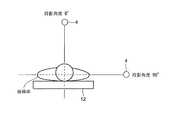
まず、ステップS1において、被検体をテーブル12に横たえさせた後、スカウトスキャンを行う。スカウトスキャンとは、X線管4とX線検出部8を回転させずに一定の投影角度に固定したまま、被検体を乗せたテーブル12を徐々に搬送しながらX線を連続的に照射して得た投影データより1枚の被検体透視像を得るものである。
【0022】
ここでは、図3に示すように、X線管4を被検体の真上にあたる投影角度0度に位置させて(モータコントローラ11の制御による)の第1のスカウトスキャンと、X線管4を被検体の真横に当たる投影角度90度に位置させての第2のスカウトスキャンを行い、2種類の被検体透視像を得る。
【0023】
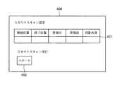
なお、スカウトスキャンの条件設定および実行指令は、例えば図4に示すような、設定画面400(操作コンソール200のCRT56に表示される)を介して行われる。図示のように、スカウトスキャン設定欄において、所定の基準位置に対するスカウトスキャンの開始位置、終了位置、X線管4に与える管電圧および管電流、そして、投影角度を設定できるようになっている。上記した2種類の被検体透視画像を得るためには、スカウトスキャン設定欄に投影角度「0」を入力した後、スカウトスキャン実行のスタートボタン402を押して、第1のスカウトスキャンを実行させる。続いて、同様に、スカウトスキャン設定欄に投影角度「90」を入力した後、スタートボタン402を押して、第2のスカウトスキャンを実行させることになる。もちろん、逆に、第2のスカウトスキャンを先に行うようにしてもよいし、第1および第2のスカウトスキャンを自動的に連続して行わせるモードを設けてもかまわない。
【0024】
この結果、図5に示す如く、テーブル12上の被検体透視画像を取得することができる。
【0025】
ところで、例えば胸部では、肺が大部分を占めるためX線減衰量は小さいのに対し、腹部では、臓器が多く存在するのでX線減衰量は大きいことは、先に説明した。また、被検体の体型も個々に異なる。
【0026】
スキャンを行うと、X線減衰量の大きい部位における投影データのS/Nが、X線減衰量の小さい部位のそれより低下してしまう場合がある。これに対処するためX線量を大きくしてスキャンすれば、部位に関係なく良好なS/Nが得られるものの、必要以上の被曝がなされるので避けなければならない。
【0027】
このような問題を解決するものとして、X線量を決定するX線管4に与える管電流値を、被検体のスキャン位置に応じて自動制御する、いわゆるAuto mAという技術が知られている。この技術を用いると、X線減衰量が異なる被検体の部位に応じた適切なX線量を設定することができ、無駄な被曝を抑えつつ、良好なS/Nを有する断層像を得ることができる。
【0028】
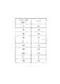
実施形態においては、このAuto mAの技術を利用する。そこで、CPU21はステップS2において、Auto mAの算定を行う。具体的には、ステップS1で得られた2種類の投影データを用いて、被検体の各スキャン位置における体幅および体厚情報を得る。被検体の断面は一般に円形とはいえず、むしろ楕円に近いことから、形状によるノイズが発生する。そこで、上記の体幅/体厚情報に基づいて、各スライス位置における楕円率を算出するとともに、X線減衰量に基づいて、各スライス位置におけるスライス面の断面積を算出することで、ノイズを所定の範囲とするように、スライス位置ごとの管電流を算定する。図6は、スキャン位置と算定管電流との対応関係の例を示すグラフである。このグラフに示されるスキャン位置と算定管電流との対応関係は、Auto mAテーブル53aとしてRAM53内に作成される。
【0029】
Auto mAテーブル53aの構成は、図7に示すとおりであって、所定の基準位置に対するスキャン位置(単位はmm)と、そのスキャン位置における管電流値(単位はmA)の組み合わせが記述されている。
【0030】
このようにしてAuto mAテーブル53aが作成されると、処理はステップS3に進む。
【0031】
ステップS3では、まず、ステップS2で得られたAuto mAテーブル53aを参照して、スキャン位置を移動させたときの算定管電流値の変動に基づいて、各スキャン位置における部位のX線減衰量の変動のようすを推定する。
【0032】
先の説明から明らかなように、Auto mAによって、X線減衰量の大きいスキャン位置では比較的大きな管電流値が算定され、X線減衰量の小さいスキャン位置では比較的小さな管電流値が算定される。
【0033】
したがって、隣り合うスキャン位置で算定管電流値の変動が大きければ、当該スキャン位置は、X線減衰量の変動が大きい部位、すなわち、スライス位置ごとの各臓器形状が大きく変化するような部位であると推測できる。このような部位では、高いz軸方向の分解能が求められるであろうから、ピッチを小さく設定することになる。
【0034】
逆に、隣り合うスキャン位置で算定管電流値の変動が小さければ、当該スキャン位置は、X線減衰量の変動が小さい部位、すなわち、スライス位置ごとの各臓器形状は大きく変化していないような部位であろうと推測できる。このような部位では、高いz軸方向の分解能は求められないであろうから、ピッチを大きく設定して撮影時間の短縮を図ることが可能である。
【0035】
実施形態では、各スキャン位置における部位のX線減衰量の変動のようすを推定するために、隣接するスキャン位置に対する算定管電流値の分散σを求める。図8(a)に示すようなスキャン位置と算定管電流値との関係(ステップS1で求められた関係)より算出した、隣接するスキャン位置に対する算定管電流値の分散σの一例を、同図(b)に示す。
【0036】
そして、この分散σに対するしきい値thを設定し(同図(b)を参照)、スキャン位置ごとにしきい値判定を行う。そして、しきい値th以上の分散を有するスキャン位置ではピッチを所定の小さな値(例えば2.5)に設定し、しきい値に満たない分散を有するスキャン位置ではピッチを所定の大きな値(例えば4.0)に設定する。同図(c)は、このしきい値判定の結果を示すグラフである。このグラフに示されるスキャン位置とピッチとの対応関係は、ピッチテーブル53bとしてRAM53内に作成される。
【0037】
ピッチテーブル53bの構成は、図9に示すとおりであって、所定の基準位置に対するスキャン位置(単位はmm)と、そのスキャン位置におけるピッチの組み合わせが記述されている。
【0038】
このようにしてピッチテーブル53bが作成されると、処理はステップS4に進み、スキャン計画を行う。このスキャン計画は一般には、CRT56に表示されるスキャン計画画面に、スキャン開始位置、終了位置、スライス厚等の項目を入力していくことで行われる。設定されたスキャン条件は、RAM53にスキャン条件設定ファイル53cとして作成、保存される。
【0039】
以上の処理を経て、RAM53に記憶されたAuto mAテーブル53a、ピッチテーブル53b、およびスキャン条件に従って、スキャンを実施することになる。
【0040】
ステップS5では、スキャン開始指示がなされたか否かを、キーボード57またはマウス58の入力に基づき判断する。
【0041】
スキャン開始指示がなされると、ステップS6に進み、テーブルモータ13を駆動して、被検体を横たえたテーブル12を、設定されたスキャン開始位置に基づく初期スキャン位置まで搬送する。
【0042】
そして、ステップS7に進み、スキャンを実行する。具体的には、次のとおりである。
【0043】
まず、Auto mAテーブル53aおよびピッチテーブル53bから各々、初期スキャン位置に対応する算定管電流値およびピッチを読み出す。ピッチは、ガントリ3の回転中心におけるスライス厚Tを乗じることによって、被検体の搬送速度にあたる、1スキャンあたりのテーブル12の搬送量に変換する。そして、これら算定管電流値および搬送量をはじめ、設定されたスキャン条件のうち必要な情報をパラメータとするスキャン開始コマンドをガントリ装置100に送出する。
【0044】
ガントリ装置100のメインコントローラ1は、このコマンドを受けてスキャン動作を開始することになるが、ここで特に、パラメータとして受け取った算定管電流値をX線管4に与えるようにX線管コントローラ5を制御し、また、受け取った搬送量を実現する搬送速度でテーブル12が搬送されるようにテーブルモータコントローラ13を制御したうえで、スキャンを行う。
【0045】
1スキャンを終えると、ステップS8で、スキャン区間の終端に達したと判断されるまで、スキャンを繰り返す。このときメインコントローラ1は、RAM53内のAuto mAテーブル53aおよびピッチテーブル53bより各々、後続するスキャン位置に対応する算定管電流値およびピッチを順次読み出しながら、それに従ってX線管コントローラ5およびテーブルモータコントローラ13を制御しつつスキャンを継続することになる。
【0046】
また、上記したステップS7においては、スキャンによってデータ収集部9で収集された投影データが操作コンソール200に転送されてくるので、CPU51は、画像再構成処理を行って断層像を作成し、CRT56に表示する。
【0047】
なお、先にも説明したとおり、ヘリカルスキャンの場合は、目的のスライス位置における投影データは、1つの投影角度におけるデータしか収集されないので、画像再構成処理に先立ち、投影データをz軸方向に補間することが必要である。補間方法としては、基本的には、360度補間法、対向ビーム補間法等の、公知の技術を用いることができる。ただし、実施形態における補間演算においては、ピッチを、スキャン位置zを変数とするピッチP(z)として取り扱うことになる。
【0048】
さらに、画像再構成処理においては、断層像のスライス厚を一定に保つために、ピッチP(z)に応じて使用するデータ範囲と重み付け係数を最適化することも可能である。
【0049】
また、上記した実施形態では、隣接するスキャン位置に対する算定管電流値の分散σに対するスキャン位置ごとのしきい値判定に基づき、ピッチを2段階に設定するようにした(図8(c)を参照)が、分散σ(z)に応じてピッチを連続的に変化させるようにしてもよい。例えば、
P(z)=f(σ(z))=A/σ+B (ただし、A,Bは定数)
としてピッチを設定することができる。
【0050】
以上説明したように、従来のX線CTシステムでは、設定したスキャン区間における一連のヘリカルスキャンに対しては1種類のピッチしか設定することができなかったのに対し、実施形態によれば、あらかじめ各スキャン位置における部位のX線減衰量の変動のようすを推定することによって、スキャン位置ごとに最適なピッチを設定し、スキャン中にピッチを自動制御するようにしたので、ヘリカルスキャンの高速撮影のメリットを失うことなく、高画質のX線断層像を再構成することが可能となる。
【0051】
また、実施形態におけるX線CTシステムの制御のほとんどは操作コンソール200において行った。操作コンソール200の構成自体は、汎用の情報処理装置(ワークステーションやパーソナルコンピュータ等)で実現できるものであるので、ソフトウェアを同装置にインストールし、それでもって実現することも可能である。
【0052】
つまり、本発明の目的は、前述した実施形態の機能を実現するソフトウェアのプログラムコードを記録した記憶媒体(または記録媒体)を、システムあるいは装置に供給し、そのシステムあるいは装置のコンピュータ(またはCPUやMPU)が記憶媒体に格納されたプログラムコードを読み出し実行することによっても実現できるものである。この場合、記憶媒体から読み出されたプログラムコード自体が前述した実施形態の機能を実現することになり、そのプログラムコードを記憶した記憶媒体は本発明を構成することになる。また、コンピュータが読み出したプログラムコードを実行することにより、前述した実施形態の機能が実現されるだけでなく、そのプログラムコードの指示に基づき、コンピュータ上で稼働しているオペレーティングシステム(OS)などが実際の処理の一部または全部を行い、その処理によって前述した実施形態の機能が実現される場合も含まれる。
【0053】
本発明を上記記憶媒体に適用する場合、その記憶媒体には、先に説明した(図2に示す)フローチャートに対応するプログラムコードが格納されることになる。
【0054】
このようなプログラムコードを格納する記憶媒体としては、例えばフロッピーディスク、ハードディスク、光ディスク、光磁気ディスク、CD−ROM、磁気テープ、不揮発性のメモリカード、ROM等を用いることができる。更には、ネットワーク(例えばインターネット)という媒体を介してダウンロードしても良いであろう。
【0055】
【発明の効果】
以上説明したように、本発明によれば、設定したスキャン区間において一連のヘリカルスキャンを行う場合に、スキャン位置に応じてヘリカルピッチを適応的に変更することによって、ヘリカルスキャンが有する高速撮影の利点を確保しつつ、高画質のX線断層像を再構成することが可能なX線CTシステムおよび操作コンソール、それらの制御方法ならびに記憶媒体を提供することができる。
【図面の簡単な説明】
【図1】実施形態に係るX線CTシステムのブロック構成図である。
【図2】実施形態におけるスキャン制御処理を示すフローチャートである。
【図3】実施形態におけるスカウトスキャンの処理を説明するための図である。
【図4】実施形態におけるスカウトスキャンの設定および実行を行うための表示画面の一例を示す図である。
【図5】実施形態における被検体透視像の一例を示す図である。
【図6】実施形態におけるAuto mAによって得られたスキャン位置と算定管電流との対応関係の例を示す図である。
【図7】実施形態におけるAuto mAテーブルの一例を示す図である。
【図8】スキャン位置とヘリカルピッチとの対応関係を決定する処理を説明するための図である。
【図9】実施形態におけるAuto mAテーブルの一例を示す図である。[0001]
BACKGROUND OF THE INVENTION
The present invention relates to an X-ray CT (Computerized Tomograpy) system and operation console for reconstructing an X-ray tomographic image of a subject by X-ray irradiation, a control method thereof, and a storage medium.
[0002]
[Prior art]
In general, an X-ray CT system collimates an X-ray fan beam from an X-ray tube, which is an X-ray generation source, at a predetermined irradiation angle (for example, 60 degrees) and then irradiates a subject, and transmits the transmitted X-ray. The X-ray tube and the X-ray detection unit for collecting projection data obtained by detecting the X-ray detection unit with a plurality of (for example, 1000) detection channels having a length depending on the X-ray irradiation angle. Performing (scanning) at a plurality of (for example, 1000) projection angles while rotating around the subject, an X-ray tomographic image is reconstructed based on projection data at each projection angle.
[0003]
Currently, as a scanning method, the subject is moved in the body axis direction (also referred to as the z-axis direction) in synchronization with the change of the projection angle (that is, the X-ray tube and the X-ray detection unit are around the subject). A helical scan method that collects projection data) is known to realize high-speed imaging.
[0004]
In the case of the helical scan, since the projection data is collected in a spiral shape, the projection data at the target slice position is collected only at one projection angle. For this reason, it is necessary to interpolate projection data in the z-axis direction prior to image reconstruction.
[0005]
By the way, in an X-ray CT system using a helical scan system, per slice thickness T (determined by the width of the X-ray detector in the z-axis direction) and one scan (collecting projection data for 360 degrees). The ratio S / T with the transport amount S of the subject is referred to as a helical pitch (hereinafter simply referred to as pitch), and this parameter is generally included in one of the scan condition setting items. For example, the pitch is 10/10 = 1 when the slice thickness is 10 mm and the transport amount of the subject per scan (that is, the transport speed) is 10 mm.
[0006]
The setting of the pitch is related to the imaging time and the resolution of the obtained tomographic image in the z-axis direction. If the pitch is increased, the shooting time will be shortened, but on the other hand, the interpolated data becomes inconsistent and causes artifacts. On the other hand, if the pitch is reduced, the shooting time becomes longer, but the interpolation accuracy is improved and the image quality of the reconstructed image can be improved. That is, the pitch is determined in a trade-off relationship between the image quality of the tomographic image and the interpolation accuracy required for the imaging target / purpose.
[0007]
[Problems to be solved by the invention]
By the way, in the chest, for example, the lungs occupy most of the X-ray attenuation amount is small, whereas in the abdomen, there are many organs, so the X-ray attenuation amount is large. Further, in the region where the lung occupies most, the shape of each organ at each slice position does not change greatly, and therefore the variation in the amount of X-ray attenuation at each slice position is small. However, as it moves toward the abdomen, the proportion of lungs decreases and the proportion of other organs (liver, etc.) increases. Therefore, it can be said that in this region, the shape of each organ at each slice position changes greatly, and the variation of the X-ray attenuation amount at each slice position is large. A high resolution in the z-axis direction will be required at a site where the variation of the X-ray attenuation amount at each slice position is large, that is, a site where the shape of each organ at each slice position changes greatly.
[0008]
However, in the conventional X-ray CT system, only one type of pitch can be set for a series of helical scans in a set scan section. Therefore, when the set scan section includes a portion where the X-ray attenuation is relatively unchanged and a portion where the X-ray attenuation is largely changed as described above, the X-ray attenuation greatly changes. There is a problem in that the contradiction of interpolation becomes large at the part to be performed, the high z-axis direction resolution cannot be ensured, and the image quality of the reconstructed image is deteriorated.
[0009]
The present invention has been made in view of such a problem, and when performing a series of helical scans in a set scan section, the helical pitch is adaptively changed according to the scan position, thereby providing a high-speed that the helical scan has. An object of the present invention is to provide an X-ray CT system and operation console capable of reconstructing a high-quality X-ray tomographic image while ensuring the advantages of imaging, a control method therefor, and a storage medium.
[0010]
[Means for Solving the Problems]
In order to achieve the above object, for example, an X-ray CT system of the present invention comprises the following arrangement. That is,
A helical scan that collects projection data while moving the subject in the body axis direction in synchronization with a change in the projection angle when X-rays generated from the X-ray tube are irradiated toward the subject is collected. An X-ray CT system for reconstructing a tomographic image of the subject based on projection data, a fluoroscopic image imaging means for imaging a subject fluoroscopic image from a plurality of projection angles orthogonal to the body axis of the subject; A determination unit that determines a control value of the conveyance speed at each scan position based on each subject fluoroscopic image captured by the fluoroscopic image imaging unit; and the conveyance speed at each scan position determined by the determination unit And a scan control means for performing a helical scan according to the control value.
[0011]
DETAILED DESCRIPTION OF THE INVENTION
Hereinafter, embodiments will be described in detail with reference to the drawings.
[0012]
(Constitution)
FIG. 1 is a block diagram of the X-ray CT system of the embodiment. As shown in the figure, the present system includes a
[0013]
The
[0014]
2 is an interface for communicating with the
[0015]
The gantry 3 also includes an X-ray detection unit 8 that detects X-rays transmitted through the subject, and a data collection unit 9 that collects projection data obtained from the transmitted X-rays obtained by the X-ray detection unit 8. Note that the X-ray detector 8 may use a multi-detector in which a plurality of detector arrays for detecting X-ray beams are provided adjacent to each other in the direction in which the subject is conveyed. An array single detector may be used.
[0016]
The
[0017]
The
[0018]
The
[0019]
The
[0020]
(processing)
The configuration of the X-ray CT system in the embodiment is generally as described above. Next, an outline of scan control processing in the X-ray CT system having such a configuration will be described with reference to the flowchart of FIG. The program corresponding to this flowchart is stored in the
[0021]
First, in step S1, a subject is laid on the table 12, and then a scout scan is performed. In the scout scan, the
[0022]
Here, as shown in FIG. 3, the
[0023]
The scout scan condition setting and execution command are performed via a setting screen 400 (displayed on the
[0024]
As a result, as shown in FIG. 5, the subject fluoroscopic image on the table 12 can be acquired.
[0025]
In the meantime, for example, in the chest, the lungs occupy most of the lungs, so the X-ray attenuation is small, whereas in the abdomen, there are many organs, so the X-ray attenuation is large. In addition, the body shape of the subject is also different.
[0026]
When scanning is performed, the S / N of projection data at a site with a large amount of X-ray attenuation may be lower than that at a site with a small amount of X-ray attenuation. In order to cope with this, if the X-ray dose is increased and scanning is performed, a good S / N can be obtained regardless of the site, but since it is exposed more than necessary, it must be avoided.
[0027]
In order to solve such a problem, a so-called Auto mA technique is known in which a tube current value applied to an
[0028]
In the embodiment, this Auto mA technology is used. Therefore, the CPU 21 calculates Auto mA in step S2. Specifically, body width and body thickness information at each scan position of the subject is obtained using the two types of projection data obtained in step S1. Since the cross section of the subject is not generally circular, it is rather close to an ellipse, and noise due to the shape is generated. Therefore, the ellipticity at each slice position is calculated based on the body width / body thickness information, and the noise is reduced by calculating the cross-sectional area of the slice surface at each slice position based on the X-ray attenuation amount. The tube current for each slice position is calculated so as to be within a predetermined range. FIG. 6 is a graph showing an example of the correspondence between the scan position and the calculated tube current. The correspondence between the scan position and the calculated tube current shown in this graph is created in the
[0029]
The configuration of the Auto mA table 53a is as shown in FIG. 7, in which a combination of a scan position (unit: mm) with respect to a predetermined reference position and a tube current value (unit: mA) at the scan position is described. .
[0030]
When the Auto mA table 53a is created in this way, the process proceeds to step S3.
[0031]
In step S3, first, referring to the Auto mA table 53a obtained in step S2, the X-ray attenuation amount of the part at each scan position is determined based on the fluctuation of the calculated tube current value when the scan position is moved. Estimate the appearance of fluctuation.
[0032]
As is clear from the above explanation, Auto mA calculates a relatively large tube current value at a scan position where the X-ray attenuation is large, and calculates a relatively small tube current value at a scan position where the X-ray attenuation is small. The
[0033]
Therefore, if the fluctuation of the calculated tube current value is large between adjacent scan positions, the scan position is a part where the fluctuation of the X-ray attenuation is large, that is, a part where the shape of each organ at each slice position changes greatly. Can be guessed. In such a part, since a high resolution in the z-axis direction will be required, the pitch is set small.
[0034]
On the contrary, if the fluctuation of the calculation tube current value is small at adjacent scan positions, the scan position is a part where the fluctuation of the X-ray attenuation is small, that is, the shape of each organ at each slice position does not change greatly. It can be assumed that it is a part. In such a part, since a high resolution in the z-axis direction will not be required, it is possible to shorten the imaging time by setting a large pitch.
[0035]
In the embodiment, in order to estimate the variation of the X-ray attenuation amount of the part at each scan position, the variance σ of the calculated tube current value with respect to the adjacent scan position is obtained. An example of the variance σ of the calculated tube current value for the adjacent scan positions calculated from the relationship between the scan position and the calculated tube current value as shown in FIG. Shown in (b).
[0036]
Then, a threshold value th is set for this variance σ (see FIG. 5B), and threshold value determination is performed for each scan position. Then, the pitch is set to a predetermined small value (for example, 2.5) at a scan position having a variance equal to or greater than the threshold th, and the pitch is set to a predetermined large value (for example, 4.0) at a scan position having a variance less than the threshold. Set to. FIG. 4C is a graph showing the result of the threshold determination. The correspondence between the scan position and the pitch shown in this graph is created in the
[0037]
The configuration of the pitch table 53b is as shown in FIG. 9, and describes a scan position (unit: mm) with respect to a predetermined reference position and a combination of pitches at the scan position.
[0038]
When the pitch table 53b is created in this way, the process proceeds to step S4 to perform a scan plan. This scan plan is generally performed by inputting items such as a scan start position, an end position, and a slice thickness on the scan plan screen displayed on the
[0039]
Through the above processing, scanning is performed according to the Auto mA table 53a, the pitch table 53b, and the scanning conditions stored in the
[0040]
In step S5, whether or not a scan start instruction has been issued is determined based on an input from the
[0041]
When a scan start instruction is given, the process proceeds to step S6, where the
[0042]
In step S7, scanning is performed. Specifically, it is as follows.
[0043]
First, the calculated tube current value and pitch corresponding to the initial scan position are read from the Auto mA table 53a and the pitch table 53b, respectively. The pitch is converted into the transport amount of the table 12 per scan corresponding to the transport speed of the subject by multiplying the slice thickness T at the rotation center of the gantry 3. Then, a scan start command is sent to the
[0044]
In response to this command, the
[0045]
When one scan is completed, the scan is repeated until it is determined in step S8 that the end of the scan section has been reached. At this time, the
[0046]
In step S7 described above, since the projection data collected by the data collection unit 9 by scanning is transferred to the
[0047]
As described above, in the case of the helical scan, projection data at a target slice position is collected only at one projection angle. Therefore, prior to image reconstruction processing, projection data is interpolated in the z-axis direction. It is necessary to. As an interpolation method, a known technique such as a 360 degree interpolation method or a counter beam interpolation method can be basically used. However, in the interpolation calculation in the embodiment, the pitch is handled as the pitch P (z) with the scan position z as a variable.
[0048]
Further, in the image reconstruction process, it is possible to optimize the data range and weighting coefficient used according to the pitch P (z) in order to keep the slice thickness of the tomographic image constant.
[0049]
In the above-described embodiment, the pitch is set in two stages based on threshold determination for each scan position with respect to the variance σ of the calculated tube current value for the adjacent scan position (see FIG. 8C). ) May change the pitch continuously according to the dispersion σ (z). For example,
P (z) = f (σ (z)) = A / σ + B (A and B are constants)
The pitch can be set as
[0050]
As described above, in the conventional X-ray CT system, only one type of pitch can be set for a series of helical scans in a set scan section. By estimating the variation in the amount of X-ray attenuation of the part at each scan position, an optimal pitch is set for each scan position, and the pitch is automatically controlled during the scan. It is possible to reconstruct a high-quality X-ray tomographic image without losing the merit.
[0051]
Further, most of the control of the X-ray CT system in the embodiment is performed on the
[0052]
That is, an object of the present invention is to supply a storage medium (or recording medium) in which a program code of software that realizes the functions of the above-described embodiments is recorded to a system or apparatus, and the computer (or CPU or CPU) of the system or apparatus. (MPU) can also be realized by reading and executing the program code stored in the storage medium. In this case, the program code itself read from the storage medium realizes the functions of the above-described embodiments, and the storage medium storing the program code constitutes the present invention. Further, by executing the program code read by the computer, not only the functions of the above-described embodiments are realized, but also an operating system (OS) running on the computer based on the instruction of the program code. A case where part or all of the actual processing is performed and the functions of the above-described embodiments are realized by the processing is also included.
[0053]
When the present invention is applied to the storage medium, the storage medium stores program codes corresponding to the flowchart described above (shown in FIG. 2).
[0054]
As a storage medium for storing such a program code, for example, a floppy disk, a hard disk, an optical disk, a magneto-optical disk, a CD-ROM, a magnetic tape, a nonvolatile memory card, a ROM, or the like can be used. Furthermore, it may be downloaded via a medium called a network (for example, the Internet).
[0055]
【The invention's effect】
As described above, according to the present invention, when a series of helical scans are performed in a set scan section, the helical pitch is adaptively changed according to the scan position, so that the advantages of high-speed imaging possessed by the helical scan are achieved. It is possible to provide an X-ray CT system and an operation console that can reconstruct a high-quality X-ray tomographic image, a control method thereof, and a storage medium.
[Brief description of the drawings]
FIG. 1 is a block configuration diagram of an X-ray CT system according to an embodiment.
FIG. 2 is a flowchart showing scan control processing in the embodiment.
FIG. 3 is a diagram for explaining scout scan processing in the embodiment;
FIG. 4 is a diagram illustrating an example of a display screen for performing setting and execution of a scout scan in the embodiment.
FIG. 5 is a diagram showing an example of a subject perspective image in the embodiment.
FIG. 6 is a diagram illustrating an example of a correspondence relationship between a scan position obtained by Auto mA and a calculation tube current in the embodiment.
FIG. 7 is a diagram illustrating an example of an Auto mA table in the embodiment.
FIG. 8 is a diagram for explaining processing for determining a correspondence relationship between a scan position and a helical pitch.
FIG. 9 is a diagram illustrating an example of an Auto mA table in the embodiment.
Claims (6)
Translated fromJapanese被検体の体軸と直交する複数の投影角度からの被検体透視像を撮像する透視像撮像手段と、
前記透視像撮像手段で撮像された各被検体透視像に基づき、各スキャン位置に対する、前記X線管に与える管電流値を算定する手段と、
隣り合う前記スキャン位置における算定管電流値の変動が比較的大きい場合は前記搬送速度を比較的小さく、隣り合うスキャン位置における算定管電流値の変動が比較的小さい場合は前記搬送速度を比較的大きくなるように、各スキャン位置における前記搬送速度の制御値を決定する決定手段と、
該決定手段で決定された各スキャン位置における前記搬送速度の制御値に従ってヘリカルスキャンを行うスキャン制御手段と、
を備えることを特徴とするX線CTシステム。Helical scan that collects projection data while transporting the subject in the body axis direction at a predetermined transport speed in synchronization with the change in projection angle when irradiating the subject with X-rays generated from the X-ray tube Performing an X-ray CT system for reconstructing a tomographic image of the subject based on the collected projection data,
Fluoroscopic image imaging means for imaging a subject fluoroscopic image from a plurality of projection angles orthogonal to the body axis of the subject;
Means for calculating a tube current value to be given to the X-ray tube with respect to each scan position, based on each subject fluoroscopic image captured by the fluoroscopic image capturing means;
When the fluctuation of the calculation tube current value at the adjacent scan position is relatively large, the conveyance speed is relatively small, and when the fluctuation of the calculation tube current value at the adjacent scan position is relatively small, the conveyance speed is relatively large. A determining meansfor determining a control value of the transport speed at each scan position ,
Scan control means for performing a helical scan according to the control value of the transport speed at each scan position determined by the determination means;
An X-ray CT system comprising:
被検体の体軸と直交する複数の投影角度からの被検体透視像を撮像する透視像撮像工程と、
前記透視像撮像手段で撮像された各被検体透視像に基づき、各スキャン位置に対する、前記X線管に与える管電流値を算定する工程と、
隣り合う前記スキャン位置における算定管電流値の変動が比較的大きい場合は前記搬送速度を比較的小さく、隣り合うスキャン位置における算定管電流値の変動が比較的小さい場合は前記搬送速度を比較的大きくなるように、各スキャン位置における前記搬送速度の制御値を決定する決定工程と、
該決定工程で決定された各スキャン位置における前記搬送速度の制御値に従ってヘリカルスキャンを行うスキャン制御工程と、
を有することを特徴とするX線CTシステムの制御方法。A helical scan that collects projection data while moving the subject in the body axis direction in synchronization with a change in the projection angle when X-rays generated from the X-ray tube are irradiated toward the subject is collected. A method for controlling an X-ray CT system for reconstructing a tomographic image of a subject based on projection data,
A fluoroscopic image imaging step of imaging a fluoroscopic image of the subject from a plurality of projection angles orthogonal to the body axis of the subject;
Calculating a tube current value to be given to the X-ray tube for each scan position based on each subject fluoroscopic image captured by the fluoroscopic image capturing means;
When the fluctuation of the calculation tube current value at the adjacent scan position is relatively large, the conveyance speed is relatively small, and when the fluctuation of the calculation tube current value at the adjacent scan position is relatively small, the conveyance speed is relatively large. A determination stepfor determining a control value of the conveyance speed at each scan position ,
A scan control step of performing a helical scan according to the control value of the transport speed at each scan position determined in the determination step;
A control method for an X-ray CT system, comprising:
被検体の体軸と直交する複数の投影角度からの被検体透視像を撮像するよう指示する第1の指示手段と、
該第1の指示手段によって、前記ガントリ装置より転送されてきた各被検体透視像に基づき、各スキャン位置に対する、前記X線管に与える管電流値を算定する手段と、
隣り合う前記スキャン位置における算定管電流値の変動が比較的大きい場合は前記搬送速度を比較的小さく、隣り合うスキャン位置における算定管電流値の変動が比較的小さい場合は前記搬送速度を比較的大きくなるように、各スキャン位置における前記搬送速度の制御値を決定する決定手段と、
該決定手段で決定された各スキャン位置における前記搬送速度の制御値に従ったヘリカルスキャンを前記ガントリ装置に行わせる第2の指示手段と、
該第2の指示手段によって、前記ガントリ装置より転送されてきた投影データに基づいて前記被検体の断層像を再構成する画像再構成手段と、を備えることを特徴とするX線CTシステムの操作コンソール。Operation of a gantry apparatus that performs a helical scan that collects projection data while moving the subject in the body axis direction in synchronization with a change in the projection angle when irradiating the subject with X-rays generated from the X-ray tube A console,
First instruction means for instructing to capture a subject perspective image from a plurality of projection angles orthogonal to the body axis of the subject;
Means for calculating a tube current value to be given to the X-ray tube for each scan position based on each subject fluoroscopic image transferred from the gantry apparatus by the first instruction means;
When the fluctuation of the calculation tube current value at the adjacent scan position is relatively large, the conveyance speed is relatively small, and when the fluctuation of the calculation tube current value at the adjacent scan position is relatively small, the conveyance speed is relatively large. A determining meansfor determining a control value of the transport speed at each scan position ,
Second instruction means for causing the gantry apparatus to perform a helical scan according to a control value of the transport speed at each scan position determined by the determination means;
An X-ray CT system operation comprising: image reconstructing means for reconstructing a tomographic image of the subject based on projection data transferred from the gantry apparatus by the second instruction means console.
被検体の体軸と直交する複数の投影角度からの被検体透視像を撮像するよう指示する第1の指示工程と、
該第1の指示工程によって、前記ガントリ装置より転送されてきた各被検体透視像に基づき、各スキャン位置に対する、前記X線管に与える管電流値を算定する工程と、
隣り合う前記スキャン位置における算定管電流値の変動が比較的大きい場合は前記搬送速度を比較的小さく、隣り合うスキャン位置における算定管電流値の変動が比較的小さい場合は前記搬送速度を比較的大きくなるように、各スキャン位置における前記搬送速度の制御値を決定する決定工程と、
該決定工程で決定された各スキャン位置における前記搬送速度の制御値に従ったヘリカルスキャンを前記ガントリ装置に行わせる第2の指示工程と、
該第2の指示工程によって、前記ガントリ装置より転送されてきた投影データに基づいて前記被検体の断層像を再構成する画像再構成工程と、を有することを特徴とするX線CTシステムの操作コンソールの制御方法。Operation of a gantry apparatus that performs a helical scan that collects projection data while moving the subject in the body axis direction in synchronization with a change in the projection angle when irradiating the subject with X-rays generated from the X-ray tube A console control method,
A first instruction step for instructing imaging of a subject fluoroscopic image from a plurality of projection angles orthogonal to the body axis of the subject;
Calculating a tube current value to be given to the X-ray tube for each scan position based on each subject fluoroscopic image transferred from the gantry apparatus by the first instruction step;
When the fluctuation of the calculation tube current value at the adjacent scan position is relatively large, the conveyance speed is relatively small, and when the fluctuation of the calculation tube current value at the adjacent scan position is relatively small, the conveyance speed is relatively large. A determination stepfor determining a control value of the conveyance speed at each scan position ,
A second instruction step for causing the gantry apparatus to perform a helical scan according to the control value of the transport speed at each scan position determined in the determination step;
An operation of reconstructing a tomographic image of the subject based on the projection data transferred from the gantry apparatus by the second instruction step. How to control the console.
被検体の体軸と直交する複数の投影角度からの被検体透視像を撮像するよう指示する第1の指示工程のプログラムコードと、
該第1の指示工程によって、前記ガントリ装置より転送されてきた各被検体透視像に基づき、各スキャン位置に対する、前記X線管に与える管電流値を算定する工程のプログラムコードと、
隣り合う前記スキャン位置における算定管電流値の変動が比較的大きい場合は前記搬送速度を比較的小さく、隣り合うスキャン位置における算定管電流値の変動が比較的小さい場合は前記搬送速度を比較的大きくなるように、各スキャン位置における前記搬送速度の制御値を決定する決定工程のプログラムコードと、
該決定工程で決定された各スキャン位置における前記搬送速度の制御値に従ったヘリカルスキャンを前記ガントリ装置に行わせる第2の指示工程のプログラムコードと、
該第2の指示工程によって、前記ガントリ装置より転送されてきた投影データに基づいて前記被検体の断層像を再構成する画像再構成工程のプログラムコードと、
を格納することを特徴とする記憶媒体。Operation of a gantry apparatus that performs a helical scan that collects projection data while moving the subject in the body axis direction in synchronization with a change in the projection angle when irradiating the subject with X-rays generated from the X-ray tube A storage medium for storing a program code for a console,
A program code of a first instruction step for instructing to capture a subject perspective image from a plurality of projection angles orthogonal to the body axis of the subject;
A program code of a step of calculating a tube current value to be given to the X-ray tube with respect to each scan position based on each subject fluoroscopic image transferred from the gantry apparatus by the first instruction step;
When the fluctuation of the calculation tube current value at the adjacent scan position is relatively large, the conveyance speed is relatively small, and when the fluctuation of the calculation tube current value at the adjacent scan position is relatively small, the conveyance speed is relatively large. So that the program code ofthe determination stepfor determining the control value of the transport speed at each scan position ;
A program code of a second instruction step for causing the gantry apparatus to perform a helical scan according to a control value of the transport speed at each scan position determined in the determination step;
A program code of an image reconstruction process for reconstructing a tomographic image of the subject based on the projection data transferred from the gantry apparatus by the second instruction process;
A storage medium characterized by storing.
Priority Applications (1)
| Application Number | Priority Date | Filing Date | Title |
|---|---|---|---|
| JP2000296914AJP4463960B2 (en) | 2000-09-28 | 2000-09-28 | X-ray CT system, operation console, control method therefor, and storage medium |
Applications Claiming Priority (1)
| Application Number | Priority Date | Filing Date | Title |
|---|---|---|---|
| JP2000296914AJP4463960B2 (en) | 2000-09-28 | 2000-09-28 | X-ray CT system, operation console, control method therefor, and storage medium |
Publications (2)
| Publication Number | Publication Date |
|---|---|
| JP2002102218A JP2002102218A (en) | 2002-04-09 |
| JP4463960B2true JP4463960B2 (en) | 2010-05-19 |
Family
ID=18779108
Family Applications (1)
| Application Number | Title | Priority Date | Filing Date |
|---|---|---|---|
| JP2000296914AExpired - Fee RelatedJP4463960B2 (en) | 2000-09-28 | 2000-09-28 | X-ray CT system, operation console, control method therefor, and storage medium |
Country Status (1)
| Country | Link |
|---|---|
| JP (1) | JP4463960B2 (en) |
Families Citing this family (12)
| Publication number | Priority date | Publication date | Assignee | Title |
|---|---|---|---|---|
| JP2006055635A (en)* | 2004-07-23 | 2006-03-02 | Toshiba Corp | X-ray computed tomography system |
| JP5317389B2 (en)* | 2006-02-03 | 2013-10-16 | ジーイー・メディカル・システムズ・グローバル・テクノロジー・カンパニー・エルエルシー | Radiation tomography equipment |
| JP5165903B2 (en)* | 2006-03-15 | 2013-03-21 | 株式会社東芝 | X-ray CT apparatus, helical pitch changing method |
| JP4909730B2 (en)* | 2006-12-15 | 2012-04-04 | 株式会社東芝 | X-ray diagnostic imaging apparatus and movement control method |
| US8311306B2 (en)* | 2008-04-30 | 2012-11-13 | Otismed Corporation | System and method for image segmentation in generating computer models of a joint to undergo arthroplasty |
| JP2009165705A (en)* | 2008-01-17 | 2009-07-30 | Shimadzu Corp | Radiation imaging device |
| EP2279494B1 (en) | 2008-05-21 | 2016-11-02 | Koninklijke Philips N.V. | Dynamic adjustable source collimation during fly-by scanning |
| JP5185403B2 (en)* | 2011-02-21 | 2013-04-17 | 株式会社東芝 | X-ray tomographic imaging apparatus |
| JP5601343B2 (en)* | 2012-05-02 | 2014-10-08 | 株式会社島津製作所 | Radiation imaging device |
| US10561391B2 (en)* | 2016-08-18 | 2020-02-18 | General Electric Company | Methods and systems for computed tomography |
| CN114929111A (en) | 2019-11-14 | 2022-08-19 | Eos成像公司 | Radiological imaging method |
| CN113008913A (en)* | 2019-12-20 | 2021-06-22 | 万睿视影像有限公司 | Radiographic inspection system for pipelines and other structures using radioisotopes |
- 2000
- 2000-09-28JPJP2000296914Apatent/JP4463960B2/ennot_activeExpired - Fee Related
Also Published As
| Publication number | Publication date |
|---|---|
| JP2002102218A (en) | 2002-04-09 |
Similar Documents
| Publication | Publication Date | Title |
|---|---|---|
| JP3942178B2 (en) | X-ray CT system | |
| KR100782409B1 (en) | X-ray imaging apparatus and its control method | |
| JP4532005B2 (en) | X-ray CT apparatus and image display method thereof | |
| US6023494A (en) | Methods and apparatus for modifying slice thickness during a helical scan | |
| JP3961249B2 (en) | X-ray CT system, gantry apparatus, operation console and control method thereof, program code, and storage medium | |
| JP4535795B2 (en) | Image processing apparatus and X-ray CT system | |
| JP4463960B2 (en) | X-ray CT system, operation console, control method therefor, and storage medium | |
| JP2001276040A (en) | X-ray ct device | |
| EP0744158A2 (en) | Computed tomography scanner apparatus | |
| JP2002102217A (en) | X-ray ct system, gantory apparatus, console terminal and controlling method therefor, and storage medium | |
| JP4397490B2 (en) | X-ray CT system, operation console, control method therefor, and storage medium | |
| JP3827555B2 (en) | Gantry apparatus, X-ray CT system, operation console and control method therefor, computer program, and computer-readable storage medium | |
| JP2002177261A (en) | Ct system and its operation console, and control method and memory medium | |
| JP4458773B2 (en) | Image shooting device | |
| JP3911415B2 (en) | X-ray CT system | |
| JP2768932B2 (en) | X-ray CT system | |
| JPH07124152A (en) | X-ray CT scanner | |
| JP2003135442A (en) | X-ray ct system and control method therefor | |
| JPH119582A (en) | X-ray computed tomography apparatus | |
| JPH10314162A (en) | Radiation tomography and its device | |
| JP4587594B2 (en) | X-ray CT apparatus and control method thereof | |
| JP2005058651A (en) | X-ray ct system, and apparatus and method of image processing | |
| JP2003038478A (en) | X-ray ct system, gantry device and operation console therefor, and control method | |
| JP4951055B2 (en) | X-ray CT system and its operation console | |
| JP4785265B2 (en) | X-ray CT system, operation console thereof, and control method thereof |
Legal Events
| Date | Code | Title | Description |
|---|---|---|---|
| A625 | Written request for application examination (by other person) | Free format text:JAPANESE INTERMEDIATE CODE: A625 Effective date:20061228 | |
| A977 | Report on retrieval | Free format text:JAPANESE INTERMEDIATE CODE: A971007 Effective date:20090828 | |
| A131 | Notification of reasons for refusal | Free format text:JAPANESE INTERMEDIATE CODE: A131 Effective date:20090904 | |
| A521 | Request for written amendment filed | Free format text:JAPANESE INTERMEDIATE CODE: A523 Effective date:20091201 | |
| TRDD | Decision of grant or rejection written | ||
| A01 | Written decision to grant a patent or to grant a registration (utility model) | Free format text:JAPANESE INTERMEDIATE CODE: A01 Effective date:20100201 | |
| A01 | Written decision to grant a patent or to grant a registration (utility model) | Free format text:JAPANESE INTERMEDIATE CODE: A01 | |
| A61 | First payment of annual fees (during grant procedure) | Free format text:JAPANESE INTERMEDIATE CODE: A61 Effective date:20100218 | |
| FPAY | Renewal fee payment (event date is renewal date of database) | Free format text:PAYMENT UNTIL: 20130226 Year of fee payment:3 | |
| R150 | Certificate of patent or registration of utility model | Free format text:JAPANESE INTERMEDIATE CODE: R150 | |
| FPAY | Renewal fee payment (event date is renewal date of database) | Free format text:PAYMENT UNTIL: 20130226 Year of fee payment:3 | |
| FPAY | Renewal fee payment (event date is renewal date of database) | Free format text:PAYMENT UNTIL: 20130226 Year of fee payment:3 | |
| FPAY | Renewal fee payment (event date is renewal date of database) | Free format text:PAYMENT UNTIL: 20130226 Year of fee payment:3 | |
| LAPS | Cancellation because of no payment of annual fees |