JP4463424B2 - Improved system and method for intraluminal imaging processing - Google Patents
Improved system and method for intraluminal imaging processingDownload PDFInfo
- Publication number
- JP4463424B2 JP4463424B2JP2000578052AJP2000578052AJP4463424B2JP 4463424 B2JP4463424 B2JP 4463424B2JP 2000578052 AJP2000578052 AJP 2000578052AJP 2000578052 AJP2000578052 AJP 2000578052AJP 4463424 B2JP4463424 B2JP 4463424B2
- Authority
- JP
- Japan
- Prior art keywords
- drive cable
- ferrite core
- lumen
- catheter system
- tubular
- Prior art date
- Legal status (The legal status is an assumption and is not a legal conclusion. Google has not performed a legal analysis and makes no representation as to the accuracy of the status listed.)
- Expired - Fee Related
Links
Images


Classifications
- A—HUMAN NECESSITIES
- A61—MEDICAL OR VETERINARY SCIENCE; HYGIENE
- A61B—DIAGNOSIS; SURGERY; IDENTIFICATION
- A61B8/00—Diagnosis using ultrasonic, sonic or infrasonic waves
- A61B8/12—Diagnosis using ultrasonic, sonic or infrasonic waves in body cavities or body tracts, e.g. by using catheters
- A—HUMAN NECESSITIES
- A61—MEDICAL OR VETERINARY SCIENCE; HYGIENE
- A61B—DIAGNOSIS; SURGERY; IDENTIFICATION
- A61B8/00—Diagnosis using ultrasonic, sonic or infrasonic waves
- A61B8/44—Constructional features of the ultrasonic, sonic or infrasonic diagnostic device
- A61B8/4444—Constructional features of the ultrasonic, sonic or infrasonic diagnostic device related to the probe
- A61B8/4461—Features of the scanning mechanism, e.g. for moving the transducer within the housing of the probe
Landscapes
- Life Sciences & Earth Sciences (AREA)
- Health & Medical Sciences (AREA)
- Biomedical Technology (AREA)
- Molecular Biology (AREA)
- Nuclear Medicine, Radiotherapy & Molecular Imaging (AREA)
- Pathology (AREA)
- Radiology & Medical Imaging (AREA)
- Engineering & Computer Science (AREA)
- Physics & Mathematics (AREA)
- Heart & Thoracic Surgery (AREA)
- Medical Informatics (AREA)
- Biophysics (AREA)
- Surgery (AREA)
- Animal Behavior & Ethology (AREA)
- General Health & Medical Sciences (AREA)
- Public Health (AREA)
- Veterinary Medicine (AREA)
- Ultra Sonic Daignosis Equipment (AREA)
- Media Introduction/Drainage Providing Device (AREA)
Description
Translated fromJapanese【0001】
(発明の背景)
(1.発明の分野)
本発明は一般に医療用デバイスに関するものであり、より具体的には、可撓性の管状カテーテル本体の管腔内に配置された駆動ケーブルに作用要素が連結された、改良型カテーテルシステムに関連する。
【0002】
(2.従来技術の説明)
動脈硬化症は、アテローム性動脈硬化症としても知られているが、アテロームまたはプラークと呼ばれる血管の壁上の脂肪状物質の堆積から生じる、ありふれた人間の病気である。このような堆積物は人体四肢に血液給送する周辺血管と心臓に血液給送する冠血管の両方で発生する。堆積物が血管の局部位置で蓄積すると、血管チャネルの狭窄、すなわち、狭まりが発生する。血流が抑制され、人間の健康状態は深刻な危機状態になる。
【0003】
このような血管堆積物を低減し、除去する無数のアプローチが公知であるが、その例として、バルーンを先端に取付けたカテーテルを使用してアテロームの領域を拡張させるバルーン血管形成術、刃または切断ビットを使用してアテロームを切断し、除去するアテローム切除術、電気スパークがプラークを芯まで焼灼するスパーク間隙低下法、レーザーエネルギーを使用してアテロームの少なくとも一部を切除するレーザー血管形成術がある。狭窄の治療を容易にするために、目的の領域内の血管の内部の視覚画像を得ることが望ましいことが多い。超音波トランスデューサーのような画像化要素を備えたカテーテルを使用して、これら画像を獲得することが多い。
【0004】
多くの場合、画像化デバイスまたは介在型デバイスを備えたカテーテルシステムは、可撓性のカテーテル本体内に配置された回転可能な駆動ケーブルを備えることになる。このタイプのカテーテルは駆動ケーブルの遠位端に或る種の作用要素が固定されている。画像化システムでは、作用要素は、通常は、超音波トランスデューサー、または、超音波トランスデューサーと結合した可動ミラーである。
【0005】
回転式超音波トランスデューサーが駆動ケーブルに連結された具体的なカテーテルシステムが米国特許第4,794,931号に開示されており、この開示内容は、本文に引例として援用されている。このシステムでは、可撓性の管状カテーテル本体内に配置された駆動ケーブルを使用して、カテーテル本体に平行な軸線を中心として超音波トランスデューサーを回転させる。それにより、超音波トランスデューサーに、カテーテル本体に垂直な平面で血管の領域を走査させている。
【0006】
本発明にとって特に重要な別な例示的なカテーテルシステムでは、カテーテル本体にガイドワイヤ係合シース部材デザインが設けられ、この場合、カテーテルは別体の(可動の)ガイドワイヤを覆って導入される。このタイプのカテーテルシステムが米国特許第5,203,338号に開示されており、これは本文に引例として十分に援用されている。この特定のカテーテルシステムでは、カテーテル本体は、カテーテル本体の遠位端に装着されたガイドワイヤ管腔を備えている。ガイドワイヤ管腔と主要管腔とはウエッジによって分離され、このウエッジにより、駆動ケーブルが主要管腔を越えて前進して、ガイドワイヤ管腔内に入ることが無いことを確実にしている。
【0007】
ガイドワイヤ係合部を有するタイプのカテーテルは以下の要領で使用される。ガイドワイヤは、目的の領域、代表的には、血管内の狭窄部の領域の内部に至るまで、患者体内を前進させられる。ガイドワイヤを設置した後で、ガイドワイヤの近位端をカテーテルのガイドワイヤ管腔内に送る。次いで、カテーテルをガイドワイヤをこえて患者体内へと前進させる。主要管腔の遠位領域が目的の領域の血管内に至るまで、カテーテルを継続して患者体内へと前進させる。回転可能画像化コアのような好適な作用要素を主要管腔内に設置したまま、搬送することが可能である。
【0008】
上述のカテーテルシステムのいずれのタイプの開発についても、また、一般的なカテーテルシステム開発についても、その一般的関心事は、特定のシステムを採用している複数カテーテル間の信頼性と性能の調和を達成する能力である。この関心に応えるものとして、上記カテーテルシステムの共通構成要素を改良して、一貫した信頼性と性能とを提供する技術を提供し得るアプローチが決定されてきた。
【0009】
本発明にとっての特定の目的の1つのこのようなアプローチとして、ハブアセンブリの改良がある。ハブアセンブリは、特に、回転式トランスデューサーまたは他の作用要素への電機接続を設けている。トランスデューサー要素の回転には、固定したフェライトワイヤを経由して、回転式駆動ケーブル内に配置されたトランスデューサーリードワイヤに電気信号を送信することが必要である。信号は、周知の電気誘導プロセスにより、固定したワイヤと回転するワイヤとの間で送信される。一般に、このプロセスは小さいエアギャップにより分離された2つのフェライトを利用することを含むが、この場合、第1のフェライトは第2の固定したフェライトと相対的に回転する。第1のフェライトは、電源投入されると、電磁界を発生する。第2のフェライトは、第1のフェライトおよび第1のフェライトの電磁界に極めて近接した位置では、回路にインダクタンスを導入させる。ギャップは、回転する本体が固定された本体と接触した時には常に発生する摩擦のマイナス効果を除去するために必要となるのが一般的である。しかし、多くの回転変圧器におけるのと同様に、この導電作用に固有の電力損失および他の非効率性が存在する。例えば、労力を集約した高額な製造プロセスが無ければ、一貫したギャップ寸法を設けることは困難となるのが普通である。一貫したギャップが無い場合は、変圧器の出力性能はハブアセンブリごとに変動する可能性がある。更に、回転式のフェライトが、固定式のフェライトと思わぬ接触をすることを回避するのに十分なだけの精度で回転することを確実にすることも困難となるかもしれない。
【0010】
カテーテルシステムを改良するための多数の他のアプローチは、駆動ケーブルに関している。駆動ケーブルは駆動シャフトを介して駆動モータに連結されている。駆動ケーブルは実質的にカテーテル本体の長さだけ延びて、可撓性のトルク伝達性要素として作用し、電気トランスデューサーを回転させる。駆動ケーブルは、捩れ剛性と可撓性とを供与するために、コイル状に構成されている。これにより、駆動ケーブルが人体血管系の蛇行する管腔を縦走することが可能となる。駆動ケーブルは、コイル状ケーブル本体により同軸の態様で封入されたトランスデューサーリードワイヤを備え得るが、これは米国特許第5,503,155号に開示されており、この開示内容が本文に引例として援用されている。
【0011】
上述の駆動ケーブルの1つの潜在的欠陥は、その延び易さである。駆動ケーブルの延びは、代表的には、除去処置手順期間中、画像化コアを可撓性のカテーテル本体内部に引き入れて長手軸方向の画像化の一連の画面を獲得する引き戻しシーケンスの期間中、或いは、洗浄動作の期間中に遭遇する。血管内管腔からカテーテルを除去する時に、ユーザはカテーテル本体の近位端で「引き戻し」を行わなければならない。一般に、カテーテル本体がカテーテル本体と血管内管腔の壁との間の摩擦を受けている時には、カテーテルの運動は抑制されることがある。カテーテル本体の運動がこの態様で抑制されると、駆動ケーブルのコイルはスプリングのコイルに類似した態様で延び得る。カテーテル本体が洗浄用流体で洗い出されている間も、コイルは互いに離れる方向に延びることがある。この場合、洗浄用流体はコイルおよび作用要素にピストン効果を生じ、従って、コイルを互いに離れる方向に拡散させる。
【0012】
或る目的には伸張自在な駆動ケーブルが有利であるが、これは問題となることもあり得る。トランスデューサーリードワイヤは、駆動ケーブル管腔内に配置され、そこに固定されるが、延びる能力を備えておらず、引張力(tensile force)を受けると、トランスデューサーリードワイヤは破損し易く、この破損によりシステムの電気的継続性が遮断される。
【0013】
カテーテルシステムへの上記以外の改良としては、主要管腔の遠位端に設置されたサイドポートを通って外へ出る洗浄用流体の方向を変えることが挙げられる。一般に、サイドの出口ポートは良好に働くが、サイドの出口ポートが洗浄処置手順中にどの方向を指すかを知るのが困難なために、このサイドの出口ポートは、臨床場面では厄介となり得る。
【0014】
上記のような理由で、超音波画像化トランスデューサーのような内部作用要素と一緒に使用するための改良型カテーテルシステムを提供することが望ましい。効率的な電気誘導により、より一貫した信頼できる信号をトランスデューサー要素に供与することができる改良型ハブアセンブリを備えているカテーテルシステムを提供することが、特に望ましい。内部導電線が遮断するのを阻止するようにカテーテルの駆動ケーブルが構成されているならば、ユーザがカテーテル本体を引き戻している時、または、カテーテル本体を洗浄している時などには、当然、駆動ケーブルは強制的に延びるようにするのが更に望ましい。カテーテル本体が主要管腔およびガイドワイヤ管腔を備えて形成されている場合には、洗浄流体のはけ口用の遠位出口ポートを血流の方向と平行に設けることが、更にまた望ましい。上記目的のうちの少なくとも幾つかと、それ以外の目的が、後述の本発明によって適えられる。
【0015】
(発明の要旨)
本発明は、可撓性の管状カテーテル本体の管腔内に配置された駆動ケーブルに作用要素が連結された、改良型のカテーテルシステムに関する。作用要素は、一般に、超音波画像化トランスデューサーを備えている。以下により詳細に記載される1つの有利な改良点は、通常はフェライトとフェライトとの間のギャップが低減または除去されるように、ハブアセンブリのフェライトを構成し直すことを含んでいる。間隙を低減または除去するとは、両フェライトの2つの対面する表面の間の平均空隙が0.0005インチよりも小さく、好ましくは0.0002インチよりも小さく、最も好ましくは0.0001インチよりも小さくなることを意味する。ギャップの空隙をこの態様で低減または除去する際に、ハブアセンブリの製造はより低い精度で行うことが可能であり、これにより、全製造プロセスがより簡略かつ廉価になる。更に、ギャップの空隙を低減または除去することにより、電気信号の誘導送信をより効率的かつ少ない送信損失で達成し得る。
【0016】
別な改良点は、伸張作用を受けたときに、導電線の引張機能不全の潜在的可能性を低減する。1つの実施形態では、ひずみ解放部材が導電線に近接し、これと平行に設けられる。導電線はひずみ解放部材と相対的に緩んだ状態で配置される。従って、導電線とひずみ解放部材とが、通常は洗浄動作および/または引き戻し動作を原因として起こる引張力(stretching force)を受けると、ひずみ解放部材はその力を受けるが、導電線はその力を受けない。従って、導電線は保護されている。代替の実施形態では、導電線の一部がバネのコイルに類似する態様でループ状にされる。この構成では、導電線は、引張力(pulling force)を受けると延びることができ、力が除去されると収縮することができる。
【0017】
カテーテルシステムへの別な改良は、各層が逆巻きコイルを有している積層構造として製造された駆動ケーブルを備えている。駆動ケーブルが回転すると、コイルが伸張または収縮のいずれかを行い得るが、これにより、多層間の干渉を増大し、従って、駆動ケーブルのトルク伝達能力を増大させる。同時に、積層コイル構造は、駆動ケーブルが所要の可撓性を維持することを可能にする。
【0018】
また別な改良では、カテーテル本体の遠位先端はカテーテル管腔とガイドワイヤ管腔との間に管腔が設置されており、洗浄用流体または他の流体がガイドワイヤ管腔の遠位部を通して解放され得ることを可能にする。
【0019】
カテーテルシステムの別な改良は、変化する材料強度、剛性、および/または、壁厚さの複数管部分を有しているカテーテル管を備え得る。例えば、カテーテル本体の硬い近位部分と高度に可撓性の遠位部分に対して中間の管剛性を備えている管部分を設け得る。この中間部は近位部と遠位部との間に設置されて、遷移領域を設け得る。遷移領域は医療従事者がカテーテル本体を捩ったり、或いは、曲げたりせずに、身体管腔内へカテーテルを前進させる能力を増大させる。
【0020】
別な改良は、遠位先端の長さを増大せずに、遠位先端の画像化領域を増大させることを含み得る。画像化デバイスを備えた駆動ケーブルを前方に移動させて、主要管腔の遠位部の1箇所または複数箇所の或る内部部分を除去することにより設けられた遠位部の空間に入れる。従って、画像化平面は血管内でより深層へと透過し、画像化平面を遠隔方向に効果的に移動させ得る。
【0021】
本発明の1つの局面では、改良型のカテーテルシステムであって、(a)近位部、遠位部、および、その中を通る管腔を有している管状カテーテル本体と、(b)管腔内で回転可能に受容された駆動ケーブルとを備えたタイプのカテーテルシステムが提供される。改良型のカテーテルシステムは、駆動ケーブルの近位端に固着されたハブアセンブリを備えている。ハブアセンブリは回転変圧器を備え、この変圧器は第1のフェライトコアと第2のフェライトコアを有している。第2のフェライトコアは、先に規定したように、第1フェライトとの間に実質的に空隙ゼロの状態で、第1のフェライトコアと接触して、コアとコアの間の電気誘導を増進させる。
【0022】
別な局面では、改良型カテーテルシステムは、(a)近位部、遠位部、および、その中を通る主要管腔を有している管状カテーテル本体と、(b)ケーブル本体、および、管腔に回転可能に受容されるケーブル管腔を備えた駆動ケーブルとを有しており、駆動ケーブルは少なくとも1本のリードワイヤがケーブル管腔内に配置されるタイプのカテーテルシステムである。この改良は、リードワイヤが引張力(tensile force)を受けた時にリードワイヤにひずみ解放をもたらすように、リードワイヤに近接して配置された支持部材を備えている。支持部材は、リードワイヤよりも大きい引張力に耐え得る。通常は、支持部材は、リードワイヤよりも少なくとも約100%増から200%増の張力に耐えることができ、好ましくは約300%の張力に耐え得る。支持部材は、リードワイヤの実質的に全長分だけ延び、通常は長さの約75%から85%分だけ延び、好ましくは約95%から100%分だけ延びる。
【0023】
また別な局面では、改良型のカテーテルシステムであって、(a)近位部、遠位部、その中を通る主要管腔を備えた管状カテーテル本体と、(b)ケーブル本体、および、主要管腔に回転可能に受容されたケーブル管腔を備えた駆動ケーブルとを有しており、この駆動ケーブルは少なくとも1本のリードワイヤがケーブル管腔内に配置されているタイプのカテーテルシステムが提供される。この改良は、駆動ケーブルの一部に連結されたひずみ解放デバイスを備えている。ひずみ解放デバイスは、代表的にはバネまたはそれと同様のデバイスでリードワイヤを偏らせ、リードワイヤが駆動ケーブル内部から伸張または後退できるようにする。リードワイヤの運動は、リードワイヤを破損させ得る引張力(tensile force)をリードワイヤが直接受けることが無いように保持する。
【0024】
また別な局面では、改良型のカテーテルシステムであって、(a)近位管状部、遠位管状部、および、その中を通る管腔を備えた管状カテーテル本体と、(b)管腔内に回転可能に受容された駆動ケーブルとを有しているタイプのカテーテルシステムが提供される。この改良は、管状カテーテル本体上に遷移材料から形成された中間の管状部を含んでいる。中間部は、管状カテーテル本体上の、同様の、または、異なる曲げ剛性および/または曲げ強度を備えた2つの部分の間に設置し得る。遷移材料は遠位管状部よりも高い曲げ剛性と、近位管状部よりも低い曲げ強度とを備えているのが好ましい。一般に、中間部は50kpsi〜200kpsiの曲げ剛性、好ましくは約150kpsi〜190kpsiの曲げ剛性を有し得る。
【0025】
また別な局面では、改良型のカテーテルシステムが提供されるが、これは、(a)近位部、遠位部、および、その中を通る主要管腔を備えた管状カテーテル本体と、(b)カテーテルの遠位部上の主要管腔と同軸に接続されたガイドワイヤ管腔であって、両管腔間にウエッジが存在する、ガイドワイヤ管腔と、(c)主要管腔内に回転可能に受容された駆動ケーブルとを有しているタイプのカテーテルシステムである。この改良は、ウエッジに形成されて主要管腔とガイドワイヤ管腔との間の導通を可能にするウエッジ管腔を含む。ウエッジ管腔は主要管腔よりも直径が小さいのが好ましい。ウエッジ管腔は直径が約0.01インチと0.3インチの間であるのが好ましく、約0.012インチと0.1インチの間であるのが好ましい。
【0026】
また別な局面では、改良型のカテーテルシステムが提供されるが、これは、近位部、遠位部、および、それらの間の管腔を備えた管状カテーテル本体を有しており、管腔はその中を通して駆動ケーブルを回転可能に受容することができるタイプのカテーテルシステムである。この改良は、内側コイルと外側コイルを備えた駆動ケーブルを有している。コイルは互いに反対方向に巻回され、それにより、駆動ケーブルが回転すると、内側コイルが伸張し、その場合、駆動ケーブルが回転している時には、外側コイルは収縮する。
【0027】
また別な実施形態では、改良型のカテーテルシステムが提供されるが、これは、近位部、遠位部、および、その中を通る管腔を備えた管状カテーテル本体を有しているタイプのカテーテルシステムである。この改良は、入れ子式係合状態に配置された第1の管状部材と第2の管状部材とを備えているが、ここでは、第1の管状部材は少なくとも1部が、プラスティックまたはポリエーテルエーテルケトン(PEEK)のようなポリマー材を含む材料から形成される。
【0028】
(特定の実施形態の説明)
近位部および遠位部を備え、近位部と遠位部とを備え、両方は、近位端と、遠位端と、それらの間の主要管腔とを有しているカテーテル本体を有する血管カテーテルシステムが提供される。遠位部は、好ましくは主要管腔と同軸に、かつ、主要管腔から遠位に配置されているガイドワイヤ管腔を更に有している。駆動ケーブルが主要管腔内に配置され、この主要管腔は、通常は、管腔内で軸線方向に並進可能であり、かつ、それ自体の長手軸のまわりに回転可能である。駆動ケーブルはその遠位端に作用要素を保有しており、作用要素は通常は、超音波画像化トランスデューサーであるが、任意で、介在型装置であってもよい。駆動ケーブルの外径は、カテーテル本体の寸法の変化に順応するように変化させることができる。
【0029】
駆動ケーブルの近位端には回転式ハブアセンブリが設けられている。ハブアセンブリは、特に、送信機/受信機と作用要素との間のインピーダンスを整合させる能力を供与する。場合によっては、作用要素は超音波トランスデューサーであり得るが、これは、可変中心周波数出力を有し得る。例えば、極めて小さい冠状血管で使用されるトランスデューサーは高周波数出力(約30MHzかそれ以上)を必要とすることがあるが、大動脈のような大型血管で使用するためのトランスデューサーはより低い周波数出力(約30MHzかそれ以下)を必要とすることがある。可変周波数要件は、送信機/受信機の電子回路により認知される電気的負荷に可変性をもたらす。大半の送信機/受信機は、一貫した負荷を受けると、最も効率良く作動する。それゆえ、トランスデューサー周波数の可変性に取り組み得るインピーダンス整合回路を利用して、トランスデューサーと送信機/受信機との間のインピーダンスが整合される。インピーダンス整合回路の性能および製造の調和を確保するために、回路は回路基盤上に製造することができる。回路基盤はハブハウジング内の最も経済的で最も効率的な位置に設置することが可能である。回路基盤はハブハウジングの近位端に向けて位置決めされるのが好ましい。更に、回路を回路基板上に設置することにより、回路はハブアセンブリの製造前に設計し、試験することができるようになる。更に、どのような理由であれ回路が故障した場合には、回路基盤は容易に置換することができる。
【0030】
ここで図1および図2を参照すると、本発明の原理に従って、改良型の血管カテーテルシステム10が例示されている。改良型の血管カテーテルシステム10は、プロファイルを低減した遠位部を備えたカテーテル本体12を有している。カテーテル本体12は近位部14および遠位部16を有しており、その各々の部分が近位端と、遠位端と、それらの間の主要管腔18とを有している。遠位部16はカテーテル本体の遠位端から粘着接合部または他の接合部20まで延在し、そこから更に、メスルアー取付け具22を含めた部分まで延びている。近位部14は近位ハブアセンブリ24から第2の粘着接合部または他の接合部26まで延在し、そこから更に、オスルアー取付け具28を含めた部分まで延びている。近位部はそこを通って延在する1個の主要管腔18と、冠状血管および/または緊密な狭窄症罹病部への入来を容易にするための断面を低減した遠位領域とを有している。
【0031】
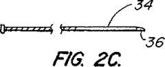
近位部14は断面が幾分大きい領域を有し、遠位管30と近位管32とを接合して、一緒に入れ子式係合状態で収容するようにしている。近位部の入れ子式管32は同軸の様式で遠位部の入れ子式管30に出し入れ自在である。これら2つの部材を互いに関して入れ子式に構成することにより、オペレータはカテーテル本体の有効な長さを変更することができる。有効な長さを変更した結果、作用要素36の駆動ケーブル34によって軸線方向への並進を増長することができる。
【0032】
好ましくは、近位部の入れ子式管32と遠位部の入れ子式管30はポリマーまたはプラスチック材料から作成されており、これが適切な曲げ剛性と実質的に大きなフープ応力に対する耐性を提供する。1つの代替の実施形態では、近位部の管32は全部が金属製であり得る。従って、入れ子式の管30および32は、引き戻しまたは他の作動期間中の屈曲または捩れを防止することが可能となる。従って、管の剛性を増大させることにより、カテーテルシステムは不均一な回転歪(NURD)の影響の少なくとも幾分かを回避する。更に、硬いオスの入れ子式管32は、医療従事者が一押しで全ストロークの能力を可能にして、入れ子の操作をいっそう容易にすることができる。この1ストローク能力は、管32が増分的に前進しないようにするので、画像化についてのより明瞭な一連の画像化シーケンスを提供する。また、オス管32の外径を減じることが可能であり、これにより、メス管30の外径も同様に低減することが可能となる。更に、比較的高い曲げ剛性を備えた遠位管30は、Nitinol(登録商標)のような管または硬化機構、或いは、ステンレス鋼硬化マンドレルの埋設型編組を利用する必要を無くする。
【0033】
適度な強さを供与するために、カテーテル本体12と入れ子式管30および32とは広範な生体適合性材料から作製することが可能であり、典型例としては、天然ポリマーまたは合成ポリマー、プラスチック材料、Nitinol(登録商標)、もしくは、同様の合金および他の金属が好ましい。これらの材料としてはシリコーンラバー、天然ラバー、ポリ塩化ビニル、ポリウレタン、ポリエステル、ポリエチレン、ポリテトラフルオロエチレン(PTFE)などが挙げられるが、ポリエーテルエーテルケトン(PEEK)であるのが好ましい。
【0034】
嵌合コネクタアセンブリ40は、近位部14の遠位端に固着された第1のコネクタすなわちオスルアー取付け具28と、遠位部16の近位端に固着された第2のコネクタすなわちメスルアー取付け具22とを備えている。これらコネクタは互いに選択的に接続されて、近位部と遠位部のそれぞれの管腔を切れ目無く、軸線方向に固定した関係で接合することができる。嵌合するメスルアー取付け具22とオスルアー取付け具28とは、カテーテル本体の近位部と遠位部とに、それぞれに、接着的に装着され、あるいは、型入れ成形でぴったり合うようにされる。好ましい実施形態では、オスルアー取付け具28はその接合部26が入れ子式アセンブリ42の遠位端に粘着的に装着される。メスルアー取付け具22は近位部のカテーテル本体の近位端に挿入成形するか、または、同様に結合することができる。嵌合式コネクタアセンブリ40は、病変部を通り抜けることに困難を有しているユーザに、短いガイドワイヤ管腔を備えた遠位シース部材を、より長い遠位部を有しているシースと置換するというオプションを可能にする。ユーザは、カテーテルシステム全体を廃棄処分にする必要なしに、近位部14または遠位部16のいずれかに装着された不都合な部分を置換することも可能である。
【0035】
好ましい実施形態では、オスルアー取付け具28は粘着点26に拡張した部分44を備え得る。拡張した部分は、駆動ケーブルと作用要素とに更なる位置決め調節を施すための一層の余裕をカテーテルシステムに設けることによって、組立て期間中に作用要素が正しい位置に設置されることを確実とする。拡張した部分を備えているメスのルアー取付け具がペンシルベニア州ベツレヘムのB. Braun Medical Inc.および他の既知の販売元から市販で入手可能である。
【0036】
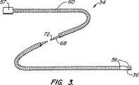
ここで図3から図5を参照して、本発明の原理に従って構成されたカテーテルシステム10の別な実施形態を説明する。駆動ケーブル34は、カテーテル本体12の近位端から遠位端までトルクを伝達するのに十分な捩れ剛性を備えた、略円形断面を有している細長の管状部材または円筒状部材であるのが好ましい。具体的な実施形態では、駆動ケーブル34は、外側コイル64と内側コイル66を備えた可撓性のある逆巻きコイル62を有している駆動ケーブル本体60を含む。導電線72は駆動ケーブル本体60の管腔70の内部に受容される。
【0037】
駆動ケーブル34は可撓性があり、カテーテルまたはシース部材内部で、冠状動脈のような蛇行する身体通路を通り、対象の標的位置まで導入することができる。駆動ケーブル34は、0.015 in−lb−inから0.15 in−lb−in の範囲にある、好ましくは、0.025 in−lb−in から0.050 in−lb−in の範囲にある曲げ剛性定数を有しているのが好ましい。駆動ケーブル34は、その遠位端に超音波トランスデューサー56を組み入れ、その近位端に接続要素57を組み入れている。駆動ケーブル本体60の外径はカテーテル本体12の寸法の変動に順応するように変更することができる。例えば、1つの実施形態では、駆動ケーブル34の外径は0.029インチから0.022インチまで低減することができ、カテーテル本体12も直径を低減することが可能となる。かかる寸法低減の恩恵は、駆動ケーブル34とカテーテル本体12との間の増加された間隙による、改善されたカテーテル調製(特に、洗浄性)である。
【0038】
本発明によれば、1対の入れ子式の逆巻き螺旋状コイル64および66は各々が、304Vステンレス鋼などの金属ワイヤから形成される。ケーブル内の各コイルは、反対方向に巻回されて、ケーブル本体が回転している時には、コイルの一方(通常は外側コイル64)が締め付けられる傾向となり、一方で同時に、他方のコイル(通常は内側コイル66)が拡張するようにしている。これはコイル構造の可撓性の性質のせいで、ケーブルに極めて高い捩れ弾性係数をもたらす一方で、曲げの弾性係数を低下させる。1つの実施形態では、内側コイル66は約0.017インチから0.019インチの範囲の直径を有している一方で、外側コイル64は、約0.029インチから0.031インチの範囲の直径を有している。コイルのワイヤ直径は、通常は、約0.002インチから0.004インチの範囲にあり、より通常には、0.0025インチから0.0035インチの範囲にある。
【0039】
代替の実施形態では、付加的なコイルが所望の範囲を越えて駆動ケーブル本体60の全直径を増大させない限り、或いは、駆動ケーブル管腔70の直径を減少させない限り、逆巻き駆動ケーブルに2つ以上のコイルを使用することができる。図5に示されているように、3つのコイルを使用できるのが好ましい。この好ましい具体例では、外側コイル64は時計方向に巻かれている。内側コイル66および66’は反時計方向に巻かれている。駆動ケーブル34が時計方向に回転している時には、外側コイル64は収縮し、内側コイル66および66’は拡張する。この構成は非常に高い捩れ弾性係数を提供し、低減された曲げ弾性係数を維持する。必要に応じて、コイルの機械的一体性を向上させるとともに、カテーテル管腔またはシース部材を供えたケーブル本体の回転を容易にするために、外側コイル64をエラストマーシース部材で被覆するのが所望であり得る。好適なエラストマーシース部材材料としては、ポリウレタン、シリコーンなどがあるが、ポリエステルが好ましい。
【0040】
ここで図4および図4Aを参照すると、上述のように、ケーブル本体60の遠位端と近位端との間の電気信号接続は、典型的には、ケーブル本体管腔70を通って延びる導電線72により設けられる。導電線72は銀、メッキ処理された銅、銅、銀、金、アルミニウム、および、それらの多様な合金のような導電性金属から形成することができる。金属コアワイヤは、ポリウレタン、ポリエステル、ナイロンなどのような有機ポリマーなどの従来型の絶縁材料により被覆することが可能である。典型例として、ワイヤの全直径は0.005インチから0.050インチの範囲にあればよく、通常は、0.005インチから0.030インチの範囲にある。1つの具体的な実施形態では、導電線72は同軸の導電線の形式であり得るが、導電線72は同軸線構成である必要はないが、その代わりに、軸線方向に平行な態様で配向された捩り合せ対か、或いは、本発明の意図から逸脱せずに、互いに不規則に巻きついた状態であり得る。
【0041】
操作について、主要管腔18が洗浄中である時、或いは、カテーテル本体が引き戻されている最中である時には、駆動ケーブル34が伸張し得る。伸張すると、逆巻きコイル62はバネと同様に作用して、細長く延びる傾向がある。図4および図4Aに示されているように、導電線72は、ひずみ解放部材68を備えたケーブル本体60の軸線方向管腔70内に配置されている。ひずみ解放部材68は導電線72よりも高い引張強度を備えている。駆動ケーブル34は機械的に伸張動作に好適であるが、ひずみ解放部材68は誘発された引張負荷を吸収して、引張力から導電線72を解放する傾向があり、そうでなければ、これはより弱い導電線72に完全に付与される。
【0042】
代替の実施形態では、ひずみ解放は、図6に示されるように、サービスループ装置80によりリードワイヤ72に提供され得る。サービスループ装置80は、ハブアセンブリ24内に配置された回転シャフト82に結合されるのが好ましい。操作において、内部リードワイヤ84はループ状構成86の装置80内に配置される。ループ86はワイヤ84を付勢させ、ケーブル34が延びると、ループ86が収縮して、リードワイヤ84が延びているケーブル内で軸線方向に移動できるようにする。駆動ケーブル34がもはや延びなくなると、ワイヤループ84がその最初のループ状形状86に戻るのが有利である。ループ装置80は封入されたチャンバー87を設けており、このチャンバーはハブアセンブリ24を体液や洗浄流体をかぶらないように保護しており、さもなければ、これら流体はワイヤ接近ポート85に入ることが可能とされる。
【0043】
ここで図7Aを参照しながら、本発明の原理に従って構成されたカテーテルシステム10の別な実施形態を説明する。ハブアセンブリ24は特に、ハブハウジング90と、回転変圧器92と、回路基板94とを有している。
【0044】
具体的な実施形態では、回転変圧器92は2つのフェライト96および98を有している。フェライト96および98は誘電電流を生じるために設けられており、この電流が電気信号を回路基板94から回転式トランスデューサーリード72を経由してトランスデューサー36に送信する。
【0045】
図7Aから認識できるように、固定式フェライトワイヤ100は電気信号を回路基板94からフェライト98へもたらす。フェライトワイヤ100はフェライト98を貫いて形成された孔を通して送られ、フェライト98の周囲を多数回、回転し、第1組のフェライト巻線を設けてから、孔から出て送り戻される。同様に、フェライト96を貫いて孔が形成されて、導電線72を孔を通して送り、フェライトの内部のまわりを多数回、巻いて第2組のフェライト巻線を設けてから、最後に孔を通って外へ送り出され得る。
【0046】
回転変圧器アセンブリ92はハブハウジングに回転可能に配置されて、第1組の巻線と第2組の巻線が互いに整列状態となって誘導結合を形成している。フェライトワイヤ100内部を流れる電流が第1組のフェライト巻線を通過し、これがフェライト98の周囲に磁界を生じる。回転フェライト96上の第2組の巻線はこの磁界内に在り、これが導電線72を通る対応する電流の流れを誘導する。この逆も真であり、導電線を通って流れる電流がフェライトワイヤ100内で電流を誘導する。
【0047】
図7Bに示されるように、フェライト96および98は点106で互いに接触する。点106における間隙は実質的にゼロである。通常は、一方のフェライトが他方のフェライトに相対的に回転する場合には、間隙ゼロは問題となる。しかし、回転変圧器92は、この応用例では、長期間にわたって実施するとは予測されておらず、60分より短いのが好ましい。さらに、ハブアセンブリ24は廃棄可能である。従って、点106における摩擦のせいであるマイナスの効果は無視できると見なすことができる。必要に応じて、点106における摩擦を低下させるために、Mylar(登録商標)、または、これと類似する材料をフェライト96とフェライト98の間に配置し得る。
【0048】
上記具体例では、フェライト96は回転駆動シャフト82と共に回転する。代替の実施形態では、フェライト98は回転し得るが、フェライト96は固定されている。
【0049】
別な代替の実施形態では、付勢部材108がハブハウジング90と固定式フェライトとの間に設置されて、回転式フェライトに抗して固定式フェライトを付勢させる。静止フェライトは回転しないが、自由に浮動する。付勢された固定式だが自由に浮動するフェライトは回転式フェライトに押圧されて、両者の間にエアギャップが無いことを確実にする。更に、付勢部材108と自由に浮動するフェライトのおかげで回転変圧器アセンブリ92を厳密に製造する必要が無くなる。例えば、回転式フェライトが回転式駆動シャフト上に不正確に位置決めされた場合は、回転時にフェライトが揺れ始め得る。付勢部材108は固定式だが自由に浮動するフェライトを揺動する回転式フェライトに押圧する。静止フェライトが自由に浮動するので、静止フェライトは回転式フェライトと同期して揺れる傾向があり、従って、両フェライト間の接触を維持している。
【0050】
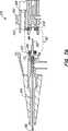
ここで図8を参照しながら、本発明の原理に従って構成されたカテーテル本体10の別な実施形態を説明する。カテーテルシステム10の1つの実施形態は、主要管腔150とガイドワイヤ管腔152とを有しているカテーテル本体12を備えている。カテーテル本体は、或る長さのポリマー材料を主要管腔150の遠位端に挿入することにより形成される。成形されたマンドレルを使用してウエッジ154を形成し、ウエッジが遠位方向傾斜面156と近位部方向傾斜面158とを有するようにしている。ウエッジ154は、加工性は勿論のこと、所要の機械的特性を備えた有機ポリマーから形成することができる。遠位方向傾斜面156は、ガイドワイヤを受容し得るように、ガイドワイヤ出口ポート160から遠位ポート162まで延在しているガイドワイヤ管腔152の一部として形成することができる。代替例として、ウエッジはバネコイルを備え得る。
【0051】
テーパ状のウエッジ154は、主要管腔150とガイドワイヤ管腔152との間に連絡を提供する、ウエッジ管腔164を有している。ウエッジ管腔164は、カテーテル本体の遠位ポート162を通して洗浄用流体を除去する目的で、流体が主要管腔150を出てガイドワイヤ管腔152内に入ることを可能にする。ウエッジ管腔164は、約0.003インチから0.025インチの直径を有するが、好ましくは、約0.011インチである。いずれの場合でも、ウエッジ管腔164を通る流れを作用要素168が最小化することを防ぐために、ウエッジ管腔164の直径は遠位ハウジング166の直径よりも小さい。
【0052】
ここで図9を参照しながら、本発明の原理に従って構成されたカテーテルシステム10の別な実施形態を説明する。上述のように、遠位端部が対象の領域200に達するか、或いは、その内部に至るまで、カテーテル本体12はガイドワイヤ上を前進される。作用要素202が適切な位置に来るまで、作用要素202をカテーテル本体12に対して移動され、診断機能を実施する。図9から認識することができるように、作用要素202が適所に在る時には、カテーテル本体の遠位先端204は、狭窄症部位200を越えて、長さYだけ延びる。例えば図に示されるように、血管206の解剖が画像化されるべき領域200を十分に越えて遠くに遠位先端が延びることを可能にしない場合には、長さYは問題となり得る。この問題を解決するために、遠位先端204の長さYはもっと短くすることができる。一般に、長さYは、約90%と30%との間で低減することが可能である。1具体例では、長さYは、約3cmから1.5cmまで低減される。
【0053】
長さYを短くするために、ガイドワイヤ管腔210の柱強度を維持してガイドワイヤを支持しながら、先端部204の外径Dをもっと大きくすることができる。外径Dは約2mmまで増大することが可能であり、好ましくは約1mmとなる。あるいは、ウエッジ214の近位部方向傾斜面212を除去することにより、主要管腔150に空間を付加することができる。面212から傾斜を除去することにより、作用要素202を表面212に向かって前方により遠くへと押しやることが可能となり、これがより短い長さYを補償することを可能にする。
【0054】
ここで図10を参照しながら、本発明の原理に従って構成されたカテーテルシステム10の別な実施形態を説明する。上述のように、カテーテル本体12の近位部セクションは、一般に比較的高い曲げ剛性を備えて、カテーテルに押し強さを提供する。対比すると、カテーテル本体12の遠位先端は、非常に可撓的に作製されて、血管の蛇行する管腔を容易に操舵走行する。典型例として、カテーテル本体12が患者体内に搬送された時には、摩擦力または他の妨害力が、特に血流遮断弁からの入来に抵抗する可能性がある。この抵抗にもかかわらず、医療従事者が継続してカテーテル本体を前方に押し続けると、導入プロセス中に患者の体外に残留していた可撓性のある遠位シース部材の一部が撓曲し、又は破損する捩れる傾向にある。
【0055】
この実施形態では、遷移カテーテルシース部材部分すなわち中間カテーテルシース部材部分217がカテーテル本体12内に形成されている。中間シース部材部分217は点222における近位部シース部材部分216と点220における遠位シース部材部分218との間で粘着的に、熱的に、或いは、同様の方法で結合され得る。これらの部分は重ね接合、突合せ接合などを利用して接続することも可能である。中間シース部材部分217は、比較的硬い近位部シース部材部分216と可撓性のある遠位先端218との間に平滑な遷移を設けている。遷移部217は、徐々に増大する剛性または柱強度を付加して、摩擦力およびその他の力を克服し、カテーテル本体12が患者の血管内へと一層容易に前進させることができるようにする。1つの実施形態では、中間シース部材部分217は約20mmと200mmの間の長さであり、40mmと100mmの間であるのが好ましい。中間シース部材部分217は点220で始まり、ここはカテーテル本体12の遠位先端204から約100mmないし400mmの間に位置し、遠位先端から150mmの位置であるのが好ましい。中間部分217は、点222付近で近位部シース部材セクション216へと移行する。
【0056】
上述のように、近位シース部材部分216は、PEEKが好ましいが、多様なポリマーから作成することが可能である。遠位シース部材部分218は、通常は、高度に可撓性のあるポリエチレンまたはこれと同様の可撓性のある材料から作成される。中間シース部材部分216は、シース部材部分216の剛性とシース部材部分218の剛性との間の範囲にわたる剛性を備えた材料から作成することができる。一般に、シース部材部分217の屈曲係数は、50kpsi から220kpsi の範囲に及び得るが、150kpsi から190kpsi の間の範囲にわたるのが好ましい。これらの材料としては、ナイロン、ポリエステル、ポリイミド、ポリオレフィンと、これらの材料の混合物を含むものが挙げられる。
【0057】
前述の発明は理解を明瞭にする目的で詳細に解説されてきたが、当業者には或る程度の修正は明瞭であるかもしれない。従って、本発明の範囲は、本件発明者が受ける権利の均等物の十全な範囲を含む添付の特許請求の範囲を参照しながら解釈されるべきである。
【図面の簡単な説明】
【図1】 図1は、本発明に従った血管カテーテルの具体的な実施形態を例示する図である。
【図2】 図2A〜2Dは、ハブと、近位管および遠位管を更に備えた近位部と、嵌合コネクタと、駆動ケーブルと、カテーテル本体の遠位部とを有している、図1のカテーテルを例示する。
【図3】 図3は、駆動ケーブル本体と、キャリアと、超音波画像化トランスデューサーとを有している駆動ケーブルを例示する図である。
【図4】 図4は、図3の駆動ケーブル本体の切り取り図である。
【図4A】 図4Aは、図3の駆動ケーブルの断面図を示す。
【図5】 図5は、本発明に従った駆動ケーブルコイルの代替の実施形態を例示する。
【図6】 図6は、本発明の局面に従ったひずみ解放デバイスを例示する図である。
【図7A】 図7Aは、本発明の原理に従った回転変圧器を備えたハブアセンブリの断面図である。
【図7B】 図7Bは、図7のハブアセンブリの断面図である。
【図8】 図8は、本発明の原理に従って構成された、主要管腔、ガイドワイヤ管腔、ウエッジ管腔を示す、カテーテル本体の遠位端の一部を例示する。
【図9】 図9は、短縮された遠位先端を備えたカテーテル本体の遠位端を例示する。
【図10】 図10は、本発明の原理に従って近位シース部と遠位シース部との間に配置された中間補強シース部を例示する。[0001]
(Background of the Invention)
(1. Field of the Invention)
The present invention relates generally to medical devices and, more particularly, to an improved catheter system in which an active element is coupled to a drive cable disposed within the lumen of a flexible tubular catheter body. .
[0002]
(2. Description of prior art)
Arteriosclerosis, also known as atherosclerosis, is a common human disease that results from the deposition of fatty substances on the walls of blood vessels called atheromas or plaques. Such deposits occur in both the peripheral blood vessels that feed blood to the human limb and the coronary blood vessels that deliver blood to the heart. When the deposit accumulates at the local position of the blood vessel, narrowing of the blood vessel channel, that is, narrowing occurs. Blood flow is suppressed, and human health becomes a serious crisis.
[0003]
A myriad of approaches to reducing and removing such vascular deposits are known, including, for example, balloon angioplasty, blade or cutting, which uses a catheter with a balloon attached to the tip to expand the area of the atheroma. There are atherectomy that uses a bit to cut and remove the atheroma, a spark gap reduction method where an electric spark cauterizes the plaque to the core, and laser angioplasty that uses laser energy to remove at least a portion of the atheroma . In order to facilitate the treatment of stenosis, it is often desirable to obtain a visual image of the interior of a blood vessel in a region of interest. These images are often acquired using a catheter with an imaging element such as an ultrasound transducer.
[0004]
Often, a catheter system with an imaging device or intervening device will comprise a rotatable drive cable disposed within a flexible catheter body. This type of catheter has a certain working element secured to the distal end of the drive cable. In an imaging system, the working element is usually an ultrasonic transducer or a movable mirror coupled to the ultrasonic transducer.
[0005]
A specific catheter system in which a rotating ultrasonic transducer is connected to a drive cable is disclosed in US Pat. No. 4,794,931, the disclosure of which is incorporated herein by reference. In this system, a drive cable disposed within a flexible tubular catheter body is used to rotate an ultrasonic transducer about an axis parallel to the catheter body. Thereby, the ultrasonic transducer is caused to scan the region of the blood vessel in a plane perpendicular to the catheter body.
[0006]
In another exemplary catheter system of particular importance to the present invention, a guide wire engaging sheath member design is provided on the catheter body, where the catheter is introduced over a separate (movable) guide wire. This type of catheter system is disclosed in US Pat. No. 5,203,338, which is fully incorporated herein by reference. In this particular catheter system, the catheter body includes a guidewire lumen attached to the distal end of the catheter body. The guide wire lumen and the main lumen are separated by a wedge, which ensures that the drive cable does not advance beyond the main lumen and enter the guide wire lumen.
[0007]
A type of catheter having a guide wire engaging portion is used as follows. The guide wire is advanced through the patient until it reaches the area of interest, typically the area of the stenosis in the blood vessel. After placement of the guide wire, the proximal end of the guide wire is delivered into the guide wire lumen of the catheter. The catheter is then advanced over the guidewire into the patient. The catheter is continuously advanced into the patient until the distal region of the main lumen is within the blood vessel of the region of interest. A suitable working element, such as a rotatable imaging core, can be transported while remaining in the main lumen.
[0008]
For any type of catheter system development described above, and for general catheter system development, the general concern is to balance the reliability and performance between multiple catheters employing a particular system. Is the ability to achieve. In response to this interest, approaches have been determined that can provide techniques that improve the common components of the catheter system to provide consistent reliability and performance.
[0009]
One such approach of particular interest to the present invention is an improved hub assembly. The hub assembly provides in particular an electrical connection to a rotary transducer or other working element. The rotation of the transducer element requires an electrical signal to be transmitted via a fixed ferrite wire to a transducer lead wire located in the rotary drive cable. The signal is transmitted between a fixed wire and a rotating wire by a well-known electrical induction process. In general, the process involves utilizing two ferrites separated by a small air gap, where the first ferrite rotates relative to the second fixed ferrite. The first ferrite generates an electromagnetic field when the power is turned on. The second ferrite introduces inductance into the circuit at a position very close to the first ferrite and the electromagnetic field of the first ferrite. The gap is generally required to eliminate the negative effect of friction that occurs whenever the rotating body comes into contact with a fixed body. However, as in many rotary transformers, there are power losses and other inefficiencies inherent in this conductive effect. For example, without an expensive manufacturing process that is labor intensive, it is usually difficult to provide consistent gap dimensions. Without a consistent gap, the output performance of the transformer can vary from hub assembly to hub assembly. It may also be difficult to ensure that the rotating ferrite rotates with sufficient accuracy to avoid unexpected contact with the stationary ferrite.
[0010]
Many other approaches for improving the catheter system relate to drive cables. The drive cable is connected to a drive motor via a drive shaft. The drive cable extends substantially the length of the catheter body and acts as a flexible torque transmitting element to rotate the electrical transducer. The drive cable is coiled to provide torsional rigidity and flexibility. As a result, the drive cable can run vertically through the meandering lumen of the human vascular system. The drive cable may comprise a transducer lead wire encapsulated in a coaxial manner by a coiled cable body, which is disclosed in US Pat. No. 5,503,155, the disclosure of which is incorporated herein by reference. Has been incorporated.
[0011]
One potential defect of the drive cable described above is its ease of extension. The extension of the drive cable is typically during the pull-back sequence during the removal procedure procedure, with the imaging core retracted inside the flexible catheter body to obtain a series of longitudinal imaging screens. Alternatively, it is encountered during the cleaning operation. When removing the catheter from the intravascular lumen, the user must “pull back” at the proximal end of the catheter body. Generally, when the catheter body is subject to friction between the catheter body and the wall of the intravascular lumen, the movement of the catheter may be inhibited. When movement of the catheter body is constrained in this manner, the drive cable coil may extend in a manner similar to the spring coil. The coils may extend away from each other while the catheter body is being rinsed with the irrigation fluid. In this case, the cleaning fluid produces a piston effect on the coil and the working element, thus diffusing the coils away from each other.
[0012]
For some purposes, an extensible drive cable is advantageous, but this can be problematic. The transducer lead wire is placed in and secured to the drive cable lumen, but does not have the ability to extend, and when subjected to a tensile force, the transducer lead wire is prone to breakage and this Damage breaks the electrical continuity of the system.
[0013]
Other improvements to the catheter system include redirecting the irrigation fluid out through a side port located at the distal end of the main lumen. In general, the side outlet port works well, but this side outlet port can be cumbersome in clinical situations because it is difficult to know which direction the side outlet port points during the cleaning procedure.
[0014]
For the reasons described above, it is desirable to provide an improved catheter system for use with an internal working element such as an ultrasound imaging transducer. It is particularly desirable to provide a catheter system with an improved hub assembly that can provide a more consistent and reliable signal to the transducer element with efficient electrical guidance. If the catheter drive cable is configured to prevent the internal conductive wire from being interrupted, such as when the user is pulling back the catheter body or cleaning the catheter body, of course, More preferably, the drive cable is forced to extend. If the catheter body is formed with a main lumen and a guidewire lumen, it is further desirable to provide a distal outlet port for the flush fluid outlet parallel to the direction of blood flow. At least some of the above objects and other objects are met by the present invention described below.
[0015]
(Summary of the Invention)
The present invention relates to an improved catheter system in which an active element is coupled to a drive cable disposed within the lumen of a flexible tubular catheter body. The working element generally comprises an ultrasound imaging transducer. One advantageous improvement, described in more detail below, typically includes reconfiguring the ferrite of the hub assembly so that the gap between the ferrite and ferrite is reduced or eliminated. To reduce or eliminate the gap, the average air gap between the two facing surfaces of both ferrites is less than 0.0005 inches, preferably less than 0.0002 inches, and most preferably less than 0.0001 inches. It means to become. In reducing or removing gap gaps in this manner, the manufacture of the hub assembly can be performed with less precision, which makes the entire manufacturing process simpler and less expensive. Furthermore, by reducing or eliminating gap gaps, inductive transmission of electrical signals can be achieved more efficiently and with less transmission loss.
[0016]
Another improvement reduces the potential for tensile failure of the conductive wire when subjected to stretching effects. In one embodiment, a strain relief member is provided proximate to and parallel to the conductive wire. The conductive wire is arranged in a loose state relative to the strain relief member. Therefore, when the conductive wire and the strain relief member are subjected to a stretching force that normally occurs due to a cleaning operation and / or a pull back operation, the strain relief member receives the force, but the conductive wire applies the force. I do not receive it. Therefore, the conductive line is protected. In an alternative embodiment, a portion of the conductive wire is looped in a manner similar to a spring coil. In this configuration, the conductive wire can extend when subjected to a pulling force and can contract when the force is removed.
[0017]
Another improvement to the catheter system includes a drive cable manufactured as a laminated structure with each layer having a reverse wound coil. As the drive cable rotates, the coil can either stretch or contract, but this increases the interference between the multilayers and thus increases the torque transmission capability of the drive cable. At the same time, the laminated coil structure allows the drive cable to maintain the required flexibility.
[0018]
In another refinement, the distal tip of the catheter body has a lumen positioned between the catheter lumen and the guidewire lumen so that cleaning fluid or other fluid can pass through the distal portion of the guidewire lumen. Allows you to be freed.
[0019]
Another improvement of the catheter system may comprise a catheter tube having multiple tube portions of varying material strength, stiffness, and / or wall thickness. For example, a tube portion may be provided that has intermediate tube stiffness relative to the rigid proximal portion and the highly flexible distal portion of the catheter body. This intermediate portion may be placed between the proximal and distal portions to provide a transition region. The transition region increases the ability of medical personnel to advance the catheter into the body lumen without twisting or bending the catheter body.
[0020]
Another improvement may include increasing the distal tip imaging area without increasing the length of the distal tip. The drive cable with the imaging device is moved forward to enter the distal space provided by removing one or more internal portions of the distal portion of the main lumen. Thus, the imaging plane can penetrate deeper into the blood vessel and effectively move the imaging plane in the remote direction.
[0021]
In one aspect of the present invention, an improved catheter system comprising: (a) a tubular catheter body having a proximal portion, a distal portion, and a lumen therethrough; and (b) a tube A catheter system of the type with a drive cable rotatably received in the cavity is provided. An improved catheter system includes a hub assembly secured to the proximal end of the drive cable. The hub assembly includes a rotary transformer, the transformer having a first ferrite core and a second ferrite core. The second ferrite core is in contact with the first ferrite core with substantially zero air gap between the first ferrite, as defined above, to enhance electrical induction between the cores. Let
[0022]
In another aspect, an improved catheter system includes (a) a tubular catheter body having a proximal portion, a distal portion, and a main lumen therethrough, and (b) a cable body and a tube. And a drive cable with a cable lumen rotatably received in the cavity, the drive cable being a type of catheter system in which at least one lead wire is disposed within the cable lumen. This improvement comprises a support member positioned proximate to the lead wire so as to provide strain relief to the lead wire when the lead wire is subjected to a tensile force. The support member can withstand a greater tensile force than the lead wire. Typically, the support member can withstand a tension of at least about 100% to 200% greater than the lead wire, and preferably can withstand a tension of about 300%. The support member extends substantially the entire length of the lead wire, typically extends from about 75% to 85% of the length, and preferably extends from about 95% to 100%.
[0023]
In another aspect, an improved catheter system comprising: (a) a tubular catheter body having a proximal portion, a distal portion, and a main lumen therethrough; (b) a cable body; A drive cable having a cable lumen rotatably received in the lumen, the drive cable being provided by a catheter system of the type in which at least one lead wire is disposed within the cable lumen Is done. This improvement includes a strain relief device coupled to a portion of the drive cable. The strain relief device typically biases the lead wire with a spring or similar device so that the lead wire can be extended or retracted from within the drive cable. The movement of the lead wire holds the lead wire so that it does not directly receive a tensile force that can break the lead wire.
[0024]
In another aspect, an improved catheter system comprising: (a) a tubular catheter body having a proximal tubular portion, a distal tubular portion, and a lumen therethrough; and (b) intraluminal A catheter system of the type having a drive cable rotatably received therein is provided. This improvement includes an intermediate tubular portion formed from a transition material on the tubular catheter body. The intermediate portion may be placed between two portions on the tubular catheter body with similar or different bending stiffness and / or bending strength. The transition material preferably has a higher bending stiffness than the distal tubular portion and a lower bending strength than the proximal tubular portion. In general, the intermediate portion can have a bending stiffness of 50 kpsi to 200 kpsi, preferably about 150 kpsi to 190 kpsi.
[0025]
In yet another aspect, an improved catheter system is provided that includes: (a) a tubular catheter body having a proximal portion, a distal portion, and a main lumen therethrough; A) a guidewire lumen coaxially connected to the main lumen on the distal portion of the catheter, with a wedge between the lumens, and (c) rotating into the main lumen A catheter system of the type having a drive cable that is received. This improvement includes a wedge lumen formed in the wedge to allow conduction between the main lumen and the guidewire lumen. The wedge lumen is preferably smaller in diameter than the main lumen. The wedge lumen is preferably between about 0.01 inches and 0.3 inches in diameter, and preferably between about 0.012 inches and 0.1 inches.
[0026]
In yet another aspect, an improved catheter system is provided that has a tubular catheter body with a proximal portion, a distal portion, and a lumen therebetween, the lumen Is a type of catheter system through which a drive cable can be rotatably received. This improvement has a drive cable with an inner coil and an outer coil. The coils are wound in opposite directions so that when the drive cable rotates, the inner coil expands, in which case the outer coil contracts when the drive cable is rotating.
[0027]
In yet another embodiment, an improved catheter system is provided, which is of the type having a tubular catheter body with a proximal portion, a distal portion, and a lumen therethrough. A catheter system; The improvement comprises a first tubular member and a second tubular member disposed in a telescoping engagement, wherein the first tubular member is at least partly plastic or polyether ether. It is formed from a material that includes a polymeric material such as a ketone (PEEK).
[0028]
(Description of specific embodiments)
A catheter body having a proximal portion and a distal portion, both having a proximal portion and a distal portion, and a main lumen therebetween. A vascular catheter system is provided. The distal portion further includes a guidewire lumen, preferably disposed coaxially with the main lumen and distal to the main lumen. A drive cable is disposed within the main lumen, which is typically axially translatable within the lumen and rotatable about its own longitudinal axis. The drive cable has a working element at its distal end, which is typically an ultrasound imaging transducer, but may optionally be an intervening device. The outer diameter of the drive cable can be varied to accommodate changes in the dimensions of the catheter body.
[0029]
A rotary hub assembly is provided at the proximal end of the drive cable. The hub assembly provides in particular the ability to match the impedance between the transmitter / receiver and the working element. In some cases, the working element may be an ultrasonic transducer, which may have a variable center frequency output. For example, transducers used in very small coronary vessels may require high frequency output (about 30 MHz or higher), while transducers for use in large vessels such as the aorta have lower frequency outputs. (Approximately 30 MHz or less). The variable frequency requirement provides variability to the electrical load perceived by the transmitter / receiver electronics. Most transmitters / receivers operate most efficiently when subjected to consistent loads. Thus, impedance matching between the transducer and the transmitter / receiver is matched utilizing an impedance matching circuit that can address transducer frequency variability. To ensure harmony between the performance and manufacturing of the impedance matching circuit, the circuit can be manufactured on a circuit board. The circuit board can be installed in the most economical and most efficient position in the hub housing. The circuit board is preferably positioned toward the proximal end of the hub housing. In addition, placing the circuit on a circuit board allows the circuit to be designed and tested prior to manufacture of the hub assembly. Furthermore, if the circuit fails for any reason, the circuit board can be easily replaced.
[0030]
Referring now to FIGS. 1 and 2, an improved vascular catheter system 10 is illustrated in accordance with the principles of the present invention. The improved vascular catheter system 10 has a
[0031]
[0032]
Preferably, the
[0033]
In order to provide moderate strength, the
[0034]
The
[0035]
In a preferred embodiment, male luer fitting 28 may include a
[0036]
With reference now to FIGS. 3-5, another embodiment of a catheter system 10 constructed in accordance with the principles of the present invention will be described. The
[0037]
The
[0038]
In accordance with the present invention, a pair of nested counter-wound
[0039]
In alternative embodiments, two or more of the reverse wound drive cable may be used unless additional coils increase the overall diameter of the
[0040]
Referring now to FIGS. 4 and 4A, as described above, the electrical signal connection between the distal and proximal ends of the
[0041]
In operation, the
[0042]
In an alternative embodiment, strain relief may be provided to the
[0043]
With reference now to FIG. 7A, another embodiment of a catheter system 10 constructed in accordance with the principles of the present invention will be described. The
[0044]
In a specific embodiment,
[0045]
As can be appreciated from FIG. 7A, the fixed
[0046]
The
[0047]
As shown in FIG. 7B,
[0048]
In the above specific example, the
[0049]
In another alternative embodiment, a biasing
[0050]
With reference now to FIG. 8, another embodiment of a catheter body 10 constructed in accordance with the principles of the present invention will be described. One embodiment of the catheter system 10 includes a
[0051]
Tapered wedge 154 has a
[0052]
With reference now to FIG. 9, another embodiment of a catheter system 10 constructed in accordance with the principles of the present invention will be described. As described above, the
[0053]
In order to shorten the length Y, the outer diameter D of the
[0054]
With reference now to FIG. 10, another embodiment of a catheter system 10 constructed in accordance with the principles of the present invention will be described. As mentioned above, the proximal section of the
[0055]
In this embodiment, a transition catheter sheath member portion or intermediate catheter
[0056]
As mentioned above, the proximal
[0057]
Although the foregoing invention has been described in detail for purposes of clarity of understanding, certain modifications may be apparent to those skilled in the art. Accordingly, the scope of the invention should be construed with reference to the appended claims, including the full scope of equivalents to which the inventors are entitled.
[Brief description of the drawings]
FIG. 1 is a diagram illustrating a specific embodiment of a vascular catheter according to the present invention.
2A-2D have a hub, a proximal portion further comprising a proximal tube and a distal tube, a mating connector, a drive cable, and a distal portion of the catheter body. 1 illustrates the catheter of FIG.
FIG. 3 is a diagram illustrating a drive cable having a drive cable body, a carrier, and an ultrasonic imaging transducer.
4 is a cutaway view of the drive cable body of FIG. 3. FIG.
FIG. 4A shows a cross-sectional view of the drive cable of FIG.
FIG. 5 illustrates an alternative embodiment of a drive cable coil according to the present invention.
FIG. 6 is a diagram illustrating a strain relief device according to an aspect of the present invention.
FIG. 7A is a cross-sectional view of a hub assembly with a rotary transformer in accordance with the principles of the present invention.
FIG. 7B is a cross-sectional view of the hub assembly of FIG.
FIG. 8 illustrates a portion of the distal end of the catheter body showing the main lumen, guidewire lumen, and wedge lumen constructed in accordance with the principles of the present invention.
FIG. 9 illustrates the distal end of a catheter body with a shortened distal tip.
FIG. 10 illustrates an intermediate reinforcing sheath portion disposed between a proximal sheath portion and a distal sheath portion in accordance with the principles of the present invention.
Claims (17)
Translated fromJapaneseApplications Claiming Priority (3)
| Application Number | Priority Date | Filing Date | Title |
|---|---|---|---|
| US10547598P | 1998-10-23 | 1998-10-23 | |
| US60/105,475 | 1998-10-23 | ||
| PCT/IB1999/001910WO2000024448A2 (en) | 1998-10-23 | 1999-10-22 | Improved system and method for intraluminal imaging |
Publications (2)
| Publication Number | Publication Date |
|---|---|
| JP2002528188A JP2002528188A (en) | 2002-09-03 |
| JP4463424B2true JP4463424B2 (en) | 2010-05-19 |
Family
ID=22306060
Family Applications (1)
| Application Number | Title | Priority Date | Filing Date |
|---|---|---|---|
| JP2000578052AExpired - Fee RelatedJP4463424B2 (en) | 1998-10-23 | 1999-10-22 | Improved system and method for intraluminal imaging processing |
Country Status (5)
| Country | Link |
|---|---|
| EP (1) | EP1123045B8 (en) |
| JP (1) | JP4463424B2 (en) |
| CA (1) | CA2347628C (en) |
| DE (3) | DE69938247T2 (en) |
| WO (1) | WO2000024448A2 (en) |
Families Citing this family (364)
| Publication number | Priority date | Publication date | Assignee | Title |
|---|---|---|---|---|
| US20070084897A1 (en) | 2003-05-20 | 2007-04-19 | Shelton Frederick E Iv | Articulating surgical stapling instrument incorporating a two-piece e-beam firing mechanism |
| US9060770B2 (en) | 2003-05-20 | 2015-06-23 | Ethicon Endo-Surgery, Inc. | Robotically-driven surgical instrument with E-beam driver |
| US11890012B2 (en) | 2004-07-28 | 2024-02-06 | Cilag Gmbh International | Staple cartridge comprising cartridge body and attached support |
| US8215531B2 (en) | 2004-07-28 | 2012-07-10 | Ethicon Endo-Surgery, Inc. | Surgical stapling instrument having a medical substance dispenser |
| US9072535B2 (en) | 2011-05-27 | 2015-07-07 | Ethicon Endo-Surgery, Inc. | Surgical stapling instruments with rotatable staple deployment arrangements |
| US11998198B2 (en) | 2004-07-28 | 2024-06-04 | Cilag Gmbh International | Surgical stapling instrument incorporating a two-piece E-beam firing mechanism |
| US9237891B2 (en) | 2005-08-31 | 2016-01-19 | Ethicon Endo-Surgery, Inc. | Robotically-controlled surgical stapling devices that produce formed staples having different lengths |
| US7669746B2 (en) | 2005-08-31 | 2010-03-02 | Ethicon Endo-Surgery, Inc. | Staple cartridges for forming staples having differing formed staple heights |
| US10159482B2 (en) | 2005-08-31 | 2018-12-25 | Ethicon Llc | Fastener cartridge assembly comprising a fixed anvil and different staple heights |
| US11246590B2 (en) | 2005-08-31 | 2022-02-15 | Cilag Gmbh International | Staple cartridge including staple drivers having different unfired heights |
| US7934630B2 (en) | 2005-08-31 | 2011-05-03 | Ethicon Endo-Surgery, Inc. | Staple cartridges for forming staples having differing formed staple heights |
| US11484312B2 (en) | 2005-08-31 | 2022-11-01 | Cilag Gmbh International | Staple cartridge comprising a staple driver arrangement |
| US20070106317A1 (en) | 2005-11-09 | 2007-05-10 | Shelton Frederick E Iv | Hydraulically and electrically actuated articulation joints for surgical instruments |
| US8708213B2 (en) | 2006-01-31 | 2014-04-29 | Ethicon Endo-Surgery, Inc. | Surgical instrument having a feedback system |
| US11793518B2 (en) | 2006-01-31 | 2023-10-24 | Cilag Gmbh International | Powered surgical instruments with firing system lockout arrangements |
| US11278279B2 (en) | 2006-01-31 | 2022-03-22 | Cilag Gmbh International | Surgical instrument assembly |
| US8820603B2 (en) | 2006-01-31 | 2014-09-02 | Ethicon Endo-Surgery, Inc. | Accessing data stored in a memory of a surgical instrument |
| US8186555B2 (en) | 2006-01-31 | 2012-05-29 | Ethicon Endo-Surgery, Inc. | Motor-driven surgical cutting and fastening instrument with mechanical closure system |
| US20110024477A1 (en) | 2009-02-06 | 2011-02-03 | Hall Steven G | Driven Surgical Stapler Improvements |
| US7845537B2 (en) | 2006-01-31 | 2010-12-07 | Ethicon Endo-Surgery, Inc. | Surgical instrument having recording capabilities |
| US11224427B2 (en) | 2006-01-31 | 2022-01-18 | Cilag Gmbh International | Surgical stapling system including a console and retraction assembly |
| US20120292367A1 (en) | 2006-01-31 | 2012-11-22 | Ethicon Endo-Surgery, Inc. | Robotically-controlled end effector |
| US20110295295A1 (en) | 2006-01-31 | 2011-12-01 | Ethicon Endo-Surgery, Inc. | Robotically-controlled surgical instrument having recording capabilities |
| US7753904B2 (en) | 2006-01-31 | 2010-07-13 | Ethicon Endo-Surgery, Inc. | Endoscopic surgical instrument with a handle that can articulate with respect to the shaft |
| US8992422B2 (en) | 2006-03-23 | 2015-03-31 | Ethicon Endo-Surgery, Inc. | Robotically-controlled endoscopic accessory channel |
| US8322455B2 (en) | 2006-06-27 | 2012-12-04 | Ethicon Endo-Surgery, Inc. | Manually driven surgical cutting and fastening instrument |
| US10568652B2 (en) | 2006-09-29 | 2020-02-25 | Ethicon Llc | Surgical staples having attached drivers of different heights and stapling instruments for deploying the same |
| US11980366B2 (en) | 2006-10-03 | 2024-05-14 | Cilag Gmbh International | Surgical instrument |
| US8632535B2 (en) | 2007-01-10 | 2014-01-21 | Ethicon Endo-Surgery, Inc. | Interlock and surgical instrument including same |
| US11291441B2 (en) | 2007-01-10 | 2022-04-05 | Cilag Gmbh International | Surgical instrument with wireless communication between control unit and remote sensor |
| US8684253B2 (en) | 2007-01-10 | 2014-04-01 | Ethicon Endo-Surgery, Inc. | Surgical instrument with wireless communication between a control unit of a robotic system and remote sensor |
| US11039836B2 (en) | 2007-01-11 | 2021-06-22 | Cilag Gmbh International | Staple cartridge for use with a surgical stapling instrument |
| US20080169333A1 (en) | 2007-01-11 | 2008-07-17 | Shelton Frederick E | Surgical stapler end effector with tapered distal end |
| US7673782B2 (en) | 2007-03-15 | 2010-03-09 | Ethicon Endo-Surgery, Inc. | Surgical stapling instrument having a releasable buttress material |
| US8931682B2 (en) | 2007-06-04 | 2015-01-13 | Ethicon Endo-Surgery, Inc. | Robotically-controlled shaft based rotary drive systems for surgical instruments |
| US11564682B2 (en) | 2007-06-04 | 2023-01-31 | Cilag Gmbh International | Surgical stapler device |
| US7753245B2 (en) | 2007-06-22 | 2010-07-13 | Ethicon Endo-Surgery, Inc. | Surgical stapling instruments |
| US11849941B2 (en) | 2007-06-29 | 2023-12-26 | Cilag Gmbh International | Staple cartridge having staple cavities extending at a transverse angle relative to a longitudinal cartridge axis |
| US8167809B2 (en) | 2007-12-20 | 2012-05-01 | Silicon Valley Medical Instruments, Inc. | Imaging probe housing with fluid flushing |
| US8378771B2 (en)* | 2007-12-20 | 2013-02-19 | Boston Scientific Scimed, Inc. | Rotary transformer |
| JP5410110B2 (en) | 2008-02-14 | 2014-02-05 | エシコン・エンド−サージェリィ・インコーポレイテッド | Surgical cutting / fixing instrument with RF electrode |
| US7819298B2 (en) | 2008-02-14 | 2010-10-26 | Ethicon Endo-Surgery, Inc. | Surgical stapling apparatus with control features operable with one hand |
| US8636736B2 (en) | 2008-02-14 | 2014-01-28 | Ethicon Endo-Surgery, Inc. | Motorized surgical cutting and fastening instrument |
| US8573465B2 (en) | 2008-02-14 | 2013-11-05 | Ethicon Endo-Surgery, Inc. | Robotically-controlled surgical end effector system with rotary actuated closure systems |
| US7866527B2 (en) | 2008-02-14 | 2011-01-11 | Ethicon Endo-Surgery, Inc. | Surgical stapling apparatus with interlockable firing system |
| US9179912B2 (en) | 2008-02-14 | 2015-11-10 | Ethicon Endo-Surgery, Inc. | Robotically-controlled motorized surgical cutting and fastening instrument |
| US11986183B2 (en) | 2008-02-14 | 2024-05-21 | Cilag Gmbh International | Surgical cutting and fastening instrument comprising a plurality of sensors to measure an electrical parameter |
| US9585657B2 (en) | 2008-02-15 | 2017-03-07 | Ethicon Endo-Surgery, Llc | Actuator for releasing a layer of material from a surgical end effector |
| US11648005B2 (en) | 2008-09-23 | 2023-05-16 | Cilag Gmbh International | Robotically-controlled motorized surgical instrument with an end effector |
| US9005230B2 (en) | 2008-09-23 | 2015-04-14 | Ethicon Endo-Surgery, Inc. | Motorized surgical instrument |
| US8210411B2 (en) | 2008-09-23 | 2012-07-03 | Ethicon Endo-Surgery, Inc. | Motor-driven surgical cutting instrument |
| US9386983B2 (en) | 2008-09-23 | 2016-07-12 | Ethicon Endo-Surgery, Llc | Robotically-controlled motorized surgical instrument |
| US8608045B2 (en) | 2008-10-10 | 2013-12-17 | Ethicon Endo-Sugery, Inc. | Powered surgical cutting and stapling apparatus with manually retractable firing system |
| US8517239B2 (en) | 2009-02-05 | 2013-08-27 | Ethicon Endo-Surgery, Inc. | Surgical stapling instrument comprising a magnetic element driver |
| RU2525225C2 (en) | 2009-02-06 | 2014-08-10 | Этикон Эндо-Серджери, Инк. | Improvement of drive surgical suturing instrument |
| WO2011011269A2 (en) | 2009-07-23 | 2011-01-27 | Waters Kendall R | Endoventricular injection catheter system with integrated echocardiographic capabilities |
| US8851354B2 (en) | 2009-12-24 | 2014-10-07 | Ethicon Endo-Surgery, Inc. | Surgical cutting instrument that analyzes tissue thickness |
| US8220688B2 (en) | 2009-12-24 | 2012-07-17 | Ethicon Endo-Surgery, Inc. | Motor-driven surgical cutting instrument with electric actuator directional control assembly |
| US8783543B2 (en) | 2010-07-30 | 2014-07-22 | Ethicon Endo-Surgery, Inc. | Tissue acquisition arrangements and methods for surgical stapling devices |
| US12213666B2 (en) | 2010-09-30 | 2025-02-04 | Cilag Gmbh International | Tissue thickness compensator comprising layers |
| US9629814B2 (en) | 2010-09-30 | 2017-04-25 | Ethicon Endo-Surgery, Llc | Tissue thickness compensator configured to redistribute compressive forces |
| US11298125B2 (en) | 2010-09-30 | 2022-04-12 | Cilag Gmbh International | Tissue stapler having a thickness compensator |
| US10945731B2 (en) | 2010-09-30 | 2021-03-16 | Ethicon Llc | Tissue thickness compensator comprising controlled release and expansion |
| US11812965B2 (en) | 2010-09-30 | 2023-11-14 | Cilag Gmbh International | Layer of material for a surgical end effector |
| US9016542B2 (en) | 2010-09-30 | 2015-04-28 | Ethicon Endo-Surgery, Inc. | Staple cartridge comprising compressible distortion resistant components |
| US9386988B2 (en) | 2010-09-30 | 2016-07-12 | Ethicon End-Surgery, LLC | Retainer assembly including a tissue thickness compensator |
| US9788834B2 (en) | 2010-09-30 | 2017-10-17 | Ethicon Llc | Layer comprising deployable attachment members |
| US9351730B2 (en) | 2011-04-29 | 2016-05-31 | Ethicon Endo-Surgery, Llc | Tissue thickness compensator comprising channels |
| US11925354B2 (en) | 2010-09-30 | 2024-03-12 | Cilag Gmbh International | Staple cartridge comprising staples positioned within a compressible portion thereof |
| US8695866B2 (en) | 2010-10-01 | 2014-04-15 | Ethicon Endo-Surgery, Inc. | Surgical instrument having a power control circuit |
| AU2012250197B2 (en) | 2011-04-29 | 2017-08-10 | Ethicon Endo-Surgery, Inc. | Staple cartridge comprising staples positioned within a compressible portion thereof |
| US9521990B2 (en) | 2011-05-11 | 2016-12-20 | Acist Medical Systems, Inc. | Variable-stiffness imaging window and production method thereof |
| US11207064B2 (en) | 2011-05-27 | 2021-12-28 | Cilag Gmbh International | Automated end effector component reloading system for use with a robotic system |
| US10905851B2 (en) | 2012-03-23 | 2021-02-02 | Acist Medical Systems, Inc. | Catheter sheath and methods thereof |
| MX358135B (en) | 2012-03-28 | 2018-08-06 | Ethicon Endo Surgery Inc | Tissue thickness compensator comprising a plurality of layers. |
| BR112014024098B1 (en) | 2012-03-28 | 2021-05-25 | Ethicon Endo-Surgery, Inc. | staple cartridge |
| JP6224070B2 (en) | 2012-03-28 | 2017-11-01 | エシコン・エンド−サージェリィ・インコーポレイテッドEthicon Endo−Surgery,Inc. | Retainer assembly including tissue thickness compensator |
| US9101358B2 (en) | 2012-06-15 | 2015-08-11 | Ethicon Endo-Surgery, Inc. | Articulatable surgical instrument comprising a firing drive |
| BR112014032776B1 (en) | 2012-06-28 | 2021-09-08 | Ethicon Endo-Surgery, Inc | SURGICAL INSTRUMENT SYSTEM AND SURGICAL KIT FOR USE WITH A SURGICAL INSTRUMENT SYSTEM |
| US9408606B2 (en) | 2012-06-28 | 2016-08-09 | Ethicon Endo-Surgery, Llc | Robotically powered surgical device with manually-actuatable reversing system |
| US9289256B2 (en) | 2012-06-28 | 2016-03-22 | Ethicon Endo-Surgery, Llc | Surgical end effectors having angled tissue-contacting surfaces |
| US9282974B2 (en) | 2012-06-28 | 2016-03-15 | Ethicon Endo-Surgery, Llc | Empty clip cartridge lockout |
| US12383267B2 (en) | 2012-06-28 | 2025-08-12 | Cilag Gmbh International | Robotically powered surgical device with manually-actuatable reversing system |
| JP6290201B2 (en) | 2012-06-28 | 2018-03-07 | エシコン・エンド−サージェリィ・インコーポレイテッドEthicon Endo−Surgery,Inc. | Lockout for empty clip cartridge |
| US11278284B2 (en) | 2012-06-28 | 2022-03-22 | Cilag Gmbh International | Rotary drive arrangements for surgical instruments |
| US20140001231A1 (en) | 2012-06-28 | 2014-01-02 | Ethicon Endo-Surgery, Inc. | Firing system lockout arrangements for surgical instruments |
| BR112015021082B1 (en) | 2013-03-01 | 2022-05-10 | Ethicon Endo-Surgery, Inc | surgical instrument |
| RU2672520C2 (en) | 2013-03-01 | 2018-11-15 | Этикон Эндо-Серджери, Инк. | Hingedly turnable surgical instruments with conducting ways for signal transfer |
| US9629629B2 (en) | 2013-03-14 | 2017-04-25 | Ethicon Endo-Surgey, LLC | Control systems for surgical instruments |
| US9808244B2 (en) | 2013-03-14 | 2017-11-07 | Ethicon Llc | Sensor arrangements for absolute positioning system for surgical instruments |
| US9826976B2 (en) | 2013-04-16 | 2017-11-28 | Ethicon Llc | Motor driven surgical instruments with lockable dual drive shafts |
| BR112015026109B1 (en) | 2013-04-16 | 2022-02-22 | Ethicon Endo-Surgery, Inc | surgical instrument |
| MX369362B (en) | 2013-08-23 | 2019-11-06 | Ethicon Endo Surgery Llc | Firing member retraction devices for powered surgical instruments. |
| US9775609B2 (en) | 2013-08-23 | 2017-10-03 | Ethicon Llc | Tamper proof circuit for surgical instrument battery pack |
| JP6568056B2 (en) | 2013-10-14 | 2019-08-28 | ボルケーノ コーポレイション | Intravascular device, system, and method |
| JP2017503540A (en) | 2013-12-19 | 2017-02-02 | アシスト・メディカル・システムズ,インコーポレイテッド | Catheter sheath system and method |
| US9962161B2 (en) | 2014-02-12 | 2018-05-08 | Ethicon Llc | Deliverable surgical instrument |
| BR112016021943B1 (en) | 2014-03-26 | 2022-06-14 | Ethicon Endo-Surgery, Llc | SURGICAL INSTRUMENT FOR USE BY AN OPERATOR IN A SURGICAL PROCEDURE |
| US10013049B2 (en) | 2014-03-26 | 2018-07-03 | Ethicon Llc | Power management through sleep options of segmented circuit and wake up control |
| US10004497B2 (en) | 2014-03-26 | 2018-06-26 | Ethicon Llc | Interface systems for use with surgical instruments |
| US20150272580A1 (en) | 2014-03-26 | 2015-10-01 | Ethicon Endo-Surgery, Inc. | Verification of number of battery exchanges/procedure count |
| US12232723B2 (en) | 2014-03-26 | 2025-02-25 | Cilag Gmbh International | Systems and methods for controlling a segmented circuit |
| US10470768B2 (en) | 2014-04-16 | 2019-11-12 | Ethicon Llc | Fastener cartridge including a layer attached thereto |
| BR112016023825B1 (en) | 2014-04-16 | 2022-08-02 | Ethicon Endo-Surgery, Llc | STAPLE CARTRIDGE FOR USE WITH A SURGICAL STAPLER AND STAPLE CARTRIDGE FOR USE WITH A SURGICAL INSTRUMENT |
| CN106456159B (en) | 2014-04-16 | 2019-03-08 | 伊西康内外科有限责任公司 | Fastener Cartridge Assembly and Nail Retainer Cover Arrangement |
| US10327764B2 (en) | 2014-09-26 | 2019-06-25 | Ethicon Llc | Method for creating a flexible staple line |
| CN106456176B (en) | 2014-04-16 | 2019-06-28 | 伊西康内外科有限责任公司 | Fastener Cartridge Including Extensions With Different Configurations |
| US20150297225A1 (en) | 2014-04-16 | 2015-10-22 | Ethicon Endo-Surgery, Inc. | Fastener cartridges including extensions having different configurations |
| US10135242B2 (en) | 2014-09-05 | 2018-11-20 | Ethicon Llc | Smart cartridge wake up operation and data retention |
| BR112017004361B1 (en) | 2014-09-05 | 2023-04-11 | Ethicon Llc | ELECTRONIC SYSTEM FOR A SURGICAL INSTRUMENT |
| US11311294B2 (en) | 2014-09-05 | 2022-04-26 | Cilag Gmbh International | Powered medical device including measurement of closure state of jaws |
| US10105142B2 (en) | 2014-09-18 | 2018-10-23 | Ethicon Llc | Surgical stapler with plurality of cutting elements |
| CN107427300B (en) | 2014-09-26 | 2020-12-04 | 伊西康有限责任公司 | Surgical suture buttresses and auxiliary materials |
| US11523821B2 (en) | 2014-09-26 | 2022-12-13 | Cilag Gmbh International | Method for creating a flexible staple line |
| US9924944B2 (en) | 2014-10-16 | 2018-03-27 | Ethicon Llc | Staple cartridge comprising an adjunct material |
| US11141153B2 (en) | 2014-10-29 | 2021-10-12 | Cilag Gmbh International | Staple cartridges comprising driver arrangements |
| US10517594B2 (en) | 2014-10-29 | 2019-12-31 | Ethicon Llc | Cartridge assemblies for surgical staplers |
| US9844376B2 (en) | 2014-11-06 | 2017-12-19 | Ethicon Llc | Staple cartridge comprising a releasable adjunct material |
| US10736636B2 (en) | 2014-12-10 | 2020-08-11 | Ethicon Llc | Articulatable surgical instrument system |
| US9844375B2 (en) | 2014-12-18 | 2017-12-19 | Ethicon Llc | Drive arrangements for articulatable surgical instruments |
| MX389118B (en) | 2014-12-18 | 2025-03-20 | Ethicon Llc | SURGICAL INSTRUMENT WITH AN ANVIL THAT CAN BE SELECTIVELY MOVED ON A DISCRETE, NON-MOBILE AXIS RELATIVE TO A STAPLE CARTRIDGE. |
| US9987000B2 (en) | 2014-12-18 | 2018-06-05 | Ethicon Llc | Surgical instrument assembly comprising a flexible articulation system |
| US9844374B2 (en) | 2014-12-18 | 2017-12-19 | Ethicon Llc | Surgical instrument systems comprising an articulatable end effector and means for adjusting the firing stroke of a firing member |
| US9943309B2 (en) | 2014-12-18 | 2018-04-17 | Ethicon Llc | Surgical instruments with articulatable end effectors and movable firing beam support arrangements |
| US10085748B2 (en) | 2014-12-18 | 2018-10-02 | Ethicon Llc | Locking arrangements for detachable shaft assemblies with articulatable surgical end effectors |
| US11154301B2 (en) | 2015-02-27 | 2021-10-26 | Cilag Gmbh International | Modular stapling assembly |
| US10245033B2 (en) | 2015-03-06 | 2019-04-02 | Ethicon Llc | Surgical instrument comprising a lockable battery housing |
| JP2020121162A (en) | 2015-03-06 | 2020-08-13 | エシコン エルエルシーEthicon LLC | Time dependent evaluation of sensor data to determine stability element, creep element and viscoelastic element of measurement |
| US10441279B2 (en) | 2015-03-06 | 2019-10-15 | Ethicon Llc | Multiple level thresholds to modify operation of powered surgical instruments |
| US9901342B2 (en)* | 2015-03-06 | 2018-02-27 | Ethicon Endo-Surgery, Llc | Signal and power communication system positioned on a rotatable shaft |
| US9993248B2 (en) | 2015-03-06 | 2018-06-12 | Ethicon Endo-Surgery, Llc | Smart sensors with local signal processing |
| US10548504B2 (en) | 2015-03-06 | 2020-02-04 | Ethicon Llc | Overlaid multi sensor radio frequency (RF) electrode system to measure tissue compression |
| US10433844B2 (en) | 2015-03-31 | 2019-10-08 | Ethicon Llc | Surgical instrument with selectively disengageable threaded drive systems |
| US10835249B2 (en) | 2015-08-17 | 2020-11-17 | Ethicon Llc | Implantable layers for a surgical instrument |
| US10105139B2 (en) | 2015-09-23 | 2018-10-23 | Ethicon Llc | Surgical stapler having downstream current-based motor control |
| US10238386B2 (en) | 2015-09-23 | 2019-03-26 | Ethicon Llc | Surgical stapler having motor control based on an electrical parameter related to a motor current |
| US10299878B2 (en) | 2015-09-25 | 2019-05-28 | Ethicon Llc | Implantable adjunct systems for determining adjunct skew |
| US11890015B2 (en) | 2015-09-30 | 2024-02-06 | Cilag Gmbh International | Compressible adjunct with crossing spacer fibers |
| US10433846B2 (en) | 2015-09-30 | 2019-10-08 | Ethicon Llc | Compressible adjunct with crossing spacer fibers |
| US10478188B2 (en) | 2015-09-30 | 2019-11-19 | Ethicon Llc | Implantable layer comprising a constricted configuration |
| US10980539B2 (en) | 2015-09-30 | 2021-04-20 | Ethicon Llc | Implantable adjunct comprising bonded layers |
| US10368865B2 (en) | 2015-12-30 | 2019-08-06 | Ethicon Llc | Mechanisms for compensating for drivetrain failure in powered surgical instruments |
| US10265068B2 (en) | 2015-12-30 | 2019-04-23 | Ethicon Llc | Surgical instruments with separable motors and motor control circuits |
| US10292704B2 (en) | 2015-12-30 | 2019-05-21 | Ethicon Llc | Mechanisms for compensating for battery pack failure in powered surgical instruments |
| BR112018016098B1 (en) | 2016-02-09 | 2023-02-23 | Ethicon Llc | SURGICAL INSTRUMENT |
| US11213293B2 (en) | 2016-02-09 | 2022-01-04 | Cilag Gmbh International | Articulatable surgical instruments with single articulation link arrangements |
| US11224426B2 (en) | 2016-02-12 | 2022-01-18 | Cilag Gmbh International | Mechanisms for compensating for drivetrain failure in powered surgical instruments |
| US10448948B2 (en) | 2016-02-12 | 2019-10-22 | Ethicon Llc | Mechanisms for compensating for drivetrain failure in powered surgical instruments |
| US11607239B2 (en) | 2016-04-15 | 2023-03-21 | Cilag Gmbh International | Systems and methods for controlling a surgical stapling and cutting instrument |
| US10456137B2 (en) | 2016-04-15 | 2019-10-29 | Ethicon Llc | Staple formation detection mechanisms |
| US10426467B2 (en) | 2016-04-15 | 2019-10-01 | Ethicon Llc | Surgical instrument with detection sensors |
| US10492783B2 (en) | 2016-04-15 | 2019-12-03 | Ethicon, Llc | Surgical instrument with improved stop/start control during a firing motion |
| US10335145B2 (en) | 2016-04-15 | 2019-07-02 | Ethicon Llc | Modular surgical instrument with configurable operating mode |
| US11179150B2 (en) | 2016-04-15 | 2021-11-23 | Cilag Gmbh International | Systems and methods for controlling a surgical stapling and cutting instrument |
| US10828028B2 (en) | 2016-04-15 | 2020-11-10 | Ethicon Llc | Surgical instrument with multiple program responses during a firing motion |
| US10357247B2 (en) | 2016-04-15 | 2019-07-23 | Ethicon Llc | Surgical instrument with multiple program responses during a firing motion |
| US20170296173A1 (en) | 2016-04-18 | 2017-10-19 | Ethicon Endo-Surgery, Llc | Method for operating a surgical instrument |
| US10363037B2 (en) | 2016-04-18 | 2019-07-30 | Ethicon Llc | Surgical instrument system comprising a magnetic lockout |
| US11317917B2 (en) | 2016-04-18 | 2022-05-03 | Cilag Gmbh International | Surgical stapling system comprising a lockable firing assembly |
| US10500000B2 (en) | 2016-08-16 | 2019-12-10 | Ethicon Llc | Surgical tool with manual control of end effector jaws |
| CN110087565A (en) | 2016-12-21 | 2019-08-02 | 爱惜康有限责任公司 | Surgical stapling system |
| US10542982B2 (en) | 2016-12-21 | 2020-01-28 | Ethicon Llc | Shaft assembly comprising first and second articulation lockouts |
| US11090048B2 (en) | 2016-12-21 | 2021-08-17 | Cilag Gmbh International | Method for resetting a fuse of a surgical instrument shaft |
| JP2020501815A (en) | 2016-12-21 | 2020-01-23 | エシコン エルエルシーEthicon LLC | Surgical stapling system |
| US20180168615A1 (en) | 2016-12-21 | 2018-06-21 | Ethicon Endo-Surgery, Llc | Method of deforming staples from two different types of staple cartridges with the same surgical stapling instrument |
| JP6983893B2 (en) | 2016-12-21 | 2021-12-17 | エシコン エルエルシーEthicon LLC | Lockout configuration for surgical end effectors and replaceable tool assemblies |
| US10980536B2 (en) | 2016-12-21 | 2021-04-20 | Ethicon Llc | No-cartridge and spent cartridge lockout arrangements for surgical staplers |
| US11134942B2 (en) | 2016-12-21 | 2021-10-05 | Cilag Gmbh International | Surgical stapling instruments and staple-forming anvils |
| US10898186B2 (en) | 2016-12-21 | 2021-01-26 | Ethicon Llc | Staple forming pocket arrangements comprising primary sidewalls and pocket sidewalls |
| US20180168625A1 (en) | 2016-12-21 | 2018-06-21 | Ethicon Endo-Surgery, Llc | Surgical stapling instruments with smart staple cartridges |
| US10973516B2 (en) | 2016-12-21 | 2021-04-13 | Ethicon Llc | Surgical end effectors and adaptable firing members therefor |
| US10582928B2 (en) | 2016-12-21 | 2020-03-10 | Ethicon Llc | Articulation lock arrangements for locking an end effector in an articulated position in response to actuation of a jaw closure system |
| JP7010957B2 (en) | 2016-12-21 | 2022-01-26 | エシコン エルエルシー | Shaft assembly with lockout |
| JP7010956B2 (en) | 2016-12-21 | 2022-01-26 | エシコン エルエルシー | How to staple tissue |
| US10813638B2 (en) | 2016-12-21 | 2020-10-27 | Ethicon Llc | Surgical end effectors with expandable tissue stop arrangements |
| US10568625B2 (en) | 2016-12-21 | 2020-02-25 | Ethicon Llc | Staple cartridges and arrangements of staples and staple cavities therein |
| US10485543B2 (en) | 2016-12-21 | 2019-11-26 | Ethicon Llc | Anvil having a knife slot width |
| US11419606B2 (en) | 2016-12-21 | 2022-08-23 | Cilag Gmbh International | Shaft assembly comprising a clutch configured to adapt the output of a rotary firing member to two different systems |
| MX2019007295A (en) | 2016-12-21 | 2019-10-15 | Ethicon Llc | Surgical instrument system comprising an end effector lockout and a firing assembly lockout. |
| US10779820B2 (en) | 2017-06-20 | 2020-09-22 | Ethicon Llc | Systems and methods for controlling motor speed according to user input for a surgical instrument |
| USD879809S1 (en) | 2017-06-20 | 2020-03-31 | Ethicon Llc | Display panel with changeable graphical user interface |
| US10307170B2 (en) | 2017-06-20 | 2019-06-04 | Ethicon Llc | Method for closed loop control of motor velocity of a surgical stapling and cutting instrument |
| US11090046B2 (en) | 2017-06-20 | 2021-08-17 | Cilag Gmbh International | Systems and methods for controlling displacement member motion of a surgical stapling and cutting instrument |
| US11382638B2 (en) | 2017-06-20 | 2022-07-12 | Cilag Gmbh International | Closed loop feedback control of motor velocity of a surgical stapling and cutting instrument based on measured time over a specified displacement distance |
| US11071554B2 (en) | 2017-06-20 | 2021-07-27 | Cilag Gmbh International | Closed loop feedback control of motor velocity of a surgical stapling and cutting instrument based on magnitude of velocity error measurements |
| US10888321B2 (en) | 2017-06-20 | 2021-01-12 | Ethicon Llc | Systems and methods for controlling velocity of a displacement member of a surgical stapling and cutting instrument |
| US11653914B2 (en) | 2017-06-20 | 2023-05-23 | Cilag Gmbh International | Systems and methods for controlling motor velocity of a surgical stapling and cutting instrument according to articulation angle of end effector |
| US11517325B2 (en) | 2017-06-20 | 2022-12-06 | Cilag Gmbh International | Closed loop feedback control of motor velocity of a surgical stapling and cutting instrument based on measured displacement distance traveled over a specified time interval |
| US10881399B2 (en) | 2017-06-20 | 2021-01-05 | Ethicon Llc | Techniques for adaptive control of motor velocity of a surgical stapling and cutting instrument |
| US10980537B2 (en) | 2017-06-20 | 2021-04-20 | Ethicon Llc | Closed loop feedback control of motor velocity of a surgical stapling and cutting instrument based on measured time over a specified number of shaft rotations |
| US11090049B2 (en) | 2017-06-27 | 2021-08-17 | Cilag Gmbh International | Staple forming pocket arrangements |
| US10993716B2 (en) | 2017-06-27 | 2021-05-04 | Ethicon Llc | Surgical anvil arrangements |
| US11266405B2 (en) | 2017-06-27 | 2022-03-08 | Cilag Gmbh International | Surgical anvil manufacturing methods |
| US11324503B2 (en) | 2017-06-27 | 2022-05-10 | Cilag Gmbh International | Surgical firing member arrangements |
| US10758232B2 (en) | 2017-06-28 | 2020-09-01 | Ethicon Llc | Surgical instrument with positive jaw opening features |
| US10903685B2 (en) | 2017-06-28 | 2021-01-26 | Ethicon Llc | Surgical shaft assemblies with slip ring assemblies forming capacitive channels |
| USD906355S1 (en) | 2017-06-28 | 2020-12-29 | Ethicon Llc | Display screen or portion thereof with a graphical user interface for a surgical instrument |
| US11259805B2 (en) | 2017-06-28 | 2022-03-01 | Cilag Gmbh International | Surgical instrument comprising firing member supports |
| US10765427B2 (en) | 2017-06-28 | 2020-09-08 | Ethicon Llc | Method for articulating a surgical instrument |
| US11246592B2 (en) | 2017-06-28 | 2022-02-15 | Cilag Gmbh International | Surgical instrument comprising an articulation system lockable to a frame |
| US11564686B2 (en) | 2017-06-28 | 2023-01-31 | Cilag Gmbh International | Surgical shaft assemblies with flexible interfaces |
| EP3420947B1 (en) | 2017-06-28 | 2022-05-25 | Cilag GmbH International | Surgical instrument comprising selectively actuatable rotatable couplers |
| US11484310B2 (en) | 2017-06-28 | 2022-11-01 | Cilag Gmbh International | Surgical instrument comprising a shaft including a closure tube profile |
| US10932772B2 (en) | 2017-06-29 | 2021-03-02 | Ethicon Llc | Methods for closed loop velocity control for robotic surgical instrument |
| US11304695B2 (en) | 2017-08-03 | 2022-04-19 | Cilag Gmbh International | Surgical system shaft interconnection |
| US11974742B2 (en) | 2017-08-03 | 2024-05-07 | Cilag Gmbh International | Surgical system comprising an articulation bailout |
| US11944300B2 (en) | 2017-08-03 | 2024-04-02 | Cilag Gmbh International | Method for operating a surgical system bailout |
| US11471155B2 (en) | 2017-08-03 | 2022-10-18 | Cilag Gmbh International | Surgical system bailout |
| US10743872B2 (en) | 2017-09-29 | 2020-08-18 | Ethicon Llc | System and methods for controlling a display of a surgical instrument |
| USD917500S1 (en) | 2017-09-29 | 2021-04-27 | Ethicon Llc | Display screen or portion thereof with graphical user interface |
| USD907647S1 (en) | 2017-09-29 | 2021-01-12 | Ethicon Llc | Display screen or portion thereof with animated graphical user interface |
| US11399829B2 (en) | 2017-09-29 | 2022-08-02 | Cilag Gmbh International | Systems and methods of initiating a power shutdown mode for a surgical instrument |
| USD907648S1 (en) | 2017-09-29 | 2021-01-12 | Ethicon Llc | Display screen or portion thereof with animated graphical user interface |
| US11090075B2 (en) | 2017-10-30 | 2021-08-17 | Cilag Gmbh International | Articulation features for surgical end effector |
| US11134944B2 (en) | 2017-10-30 | 2021-10-05 | Cilag Gmbh International | Surgical stapler knife motion controls |
| US10842490B2 (en) | 2017-10-31 | 2020-11-24 | Ethicon Llc | Cartridge body design with force reduction based on firing completion |
| US10779825B2 (en) | 2017-12-15 | 2020-09-22 | Ethicon Llc | Adapters with end effector position sensing and control arrangements for use in connection with electromechanical surgical instruments |
| US10869666B2 (en) | 2017-12-15 | 2020-12-22 | Ethicon Llc | Adapters with control systems for controlling multiple motors of an electromechanical surgical instrument |
| US10779826B2 (en) | 2017-12-15 | 2020-09-22 | Ethicon Llc | Methods of operating surgical end effectors |
| US10828033B2 (en) | 2017-12-15 | 2020-11-10 | Ethicon Llc | Handheld electromechanical surgical instruments with improved motor control arrangements for positioning components of an adapter coupled thereto |
| US10966718B2 (en) | 2017-12-15 | 2021-04-06 | Ethicon Llc | Dynamic clamping assemblies with improved wear characteristics for use in connection with electromechanical surgical instruments |
| US11071543B2 (en) | 2017-12-15 | 2021-07-27 | Cilag Gmbh International | Surgical end effectors with clamping assemblies configured to increase jaw aperture ranges |
| US11033267B2 (en) | 2017-12-15 | 2021-06-15 | Ethicon Llc | Systems and methods of controlling a clamping member firing rate of a surgical instrument |
| US11197670B2 (en) | 2017-12-15 | 2021-12-14 | Cilag Gmbh International | Surgical end effectors with pivotal jaws configured to touch at their respective distal ends when fully closed |
| USD910847S1 (en) | 2017-12-19 | 2021-02-16 | Ethicon Llc | Surgical instrument assembly |
| US10835330B2 (en) | 2017-12-19 | 2020-11-17 | Ethicon Llc | Method for determining the position of a rotatable jaw of a surgical instrument attachment assembly |
| US11020112B2 (en) | 2017-12-19 | 2021-06-01 | Ethicon Llc | Surgical tools configured for interchangeable use with different controller interfaces |
| US11076853B2 (en) | 2017-12-21 | 2021-08-03 | Cilag Gmbh International | Systems and methods of displaying a knife position during transection for a surgical instrument |
| US11129680B2 (en) | 2017-12-21 | 2021-09-28 | Cilag Gmbh International | Surgical instrument comprising a projector |
| US11311290B2 (en) | 2017-12-21 | 2022-04-26 | Cilag Gmbh International | Surgical instrument comprising an end effector dampener |
| US11179151B2 (en) | 2017-12-21 | 2021-11-23 | Cilag Gmbh International | Surgical instrument comprising a display |
| US12336705B2 (en) | 2017-12-21 | 2025-06-24 | Cilag Gmbh International | Continuous use self-propelled stapling instrument |
| US11207065B2 (en) | 2018-08-20 | 2021-12-28 | Cilag Gmbh International | Method for fabricating surgical stapler anvils |
| US11291440B2 (en) | 2018-08-20 | 2022-04-05 | Cilag Gmbh International | Method for operating a powered articulatable surgical instrument |
| US11039834B2 (en) | 2018-08-20 | 2021-06-22 | Cilag Gmbh International | Surgical stapler anvils with staple directing protrusions and tissue stability features |
| US11253256B2 (en) | 2018-08-20 | 2022-02-22 | Cilag Gmbh International | Articulatable motor powered surgical instruments with dedicated articulation motor arrangements |
| US11045192B2 (en) | 2018-08-20 | 2021-06-29 | Cilag Gmbh International | Fabricating techniques for surgical stapler anvils |
| US11324501B2 (en) | 2018-08-20 | 2022-05-10 | Cilag Gmbh International | Surgical stapling devices with improved closure members |
| US10856870B2 (en) | 2018-08-20 | 2020-12-08 | Ethicon Llc | Switching arrangements for motor powered articulatable surgical instruments |
| USD914878S1 (en) | 2018-08-20 | 2021-03-30 | Ethicon Llc | Surgical instrument anvil |
| US11083458B2 (en) | 2018-08-20 | 2021-08-10 | Cilag Gmbh International | Powered surgical instruments with clutching arrangements to convert linear drive motions to rotary drive motions |
| US10912559B2 (en) | 2018-08-20 | 2021-02-09 | Ethicon Llc | Reinforced deformable anvil tip for surgical stapler anvil |
| US20200054321A1 (en) | 2018-08-20 | 2020-02-20 | Ethicon Llc | Surgical instruments with progressive jaw closure arrangements |
| US11696761B2 (en) | 2019-03-25 | 2023-07-11 | Cilag Gmbh International | Firing drive arrangements for surgical systems |
| US11147551B2 (en) | 2019-03-25 | 2021-10-19 | Cilag Gmbh International | Firing drive arrangements for surgical systems |
| US11147553B2 (en) | 2019-03-25 | 2021-10-19 | Cilag Gmbh International | Firing drive arrangements for surgical systems |
| US11172929B2 (en) | 2019-03-25 | 2021-11-16 | Cilag Gmbh International | Articulation drive arrangements for surgical systems |
| US11903581B2 (en) | 2019-04-30 | 2024-02-20 | Cilag Gmbh International | Methods for stapling tissue using a surgical instrument |
| US11648009B2 (en) | 2019-04-30 | 2023-05-16 | Cilag Gmbh International | Rotatable jaw tip for a surgical instrument |
| US11432816B2 (en) | 2019-04-30 | 2022-09-06 | Cilag Gmbh International | Articulation pin for a surgical instrument |
| US11452528B2 (en) | 2019-04-30 | 2022-09-27 | Cilag Gmbh International | Articulation actuators for a surgical instrument |
| US11471157B2 (en) | 2019-04-30 | 2022-10-18 | Cilag Gmbh International | Articulation control mapping for a surgical instrument |
| US11253254B2 (en) | 2019-04-30 | 2022-02-22 | Cilag Gmbh International | Shaft rotation actuator on a surgical instrument |
| US11426251B2 (en) | 2019-04-30 | 2022-08-30 | Cilag Gmbh International | Articulation directional lights on a surgical instrument |
| US11051807B2 (en) | 2019-06-28 | 2021-07-06 | Cilag Gmbh International | Packaging assembly including a particulate trap |
| US11219455B2 (en) | 2019-06-28 | 2022-01-11 | Cilag Gmbh International | Surgical instrument including a lockout key |
| US11464601B2 (en) | 2019-06-28 | 2022-10-11 | Cilag Gmbh International | Surgical instrument comprising an RFID system for tracking a movable component |
| US11224497B2 (en) | 2019-06-28 | 2022-01-18 | Cilag Gmbh International | Surgical systems with multiple RFID tags |
| US11627959B2 (en) | 2019-06-28 | 2023-04-18 | Cilag Gmbh International | Surgical instruments including manual and powered system lockouts |
| US11553971B2 (en) | 2019-06-28 | 2023-01-17 | Cilag Gmbh International | Surgical RFID assemblies for display and communication |
| US11684434B2 (en) | 2019-06-28 | 2023-06-27 | Cilag Gmbh International | Surgical RFID assemblies for instrument operational setting control |
| US11426167B2 (en) | 2019-06-28 | 2022-08-30 | Cilag Gmbh International | Mechanisms for proper anvil attachment surgical stapling head assembly |
| US11478241B2 (en) | 2019-06-28 | 2022-10-25 | Cilag Gmbh International | Staple cartridge including projections |
| US11638587B2 (en) | 2019-06-28 | 2023-05-02 | Cilag Gmbh International | RFID identification systems for surgical instruments |
| US11259803B2 (en) | 2019-06-28 | 2022-03-01 | Cilag Gmbh International | Surgical stapling system having an information encryption protocol |
| US11298127B2 (en) | 2019-06-28 | 2022-04-12 | Cilag GmbH Interational | Surgical stapling system having a lockout mechanism for an incompatible cartridge |
| US11771419B2 (en) | 2019-06-28 | 2023-10-03 | Cilag Gmbh International | Packaging for a replaceable component of a surgical stapling system |
| US11497492B2 (en) | 2019-06-28 | 2022-11-15 | Cilag Gmbh International | Surgical instrument including an articulation lock |
| US11660163B2 (en) | 2019-06-28 | 2023-05-30 | Cilag Gmbh International | Surgical system with RFID tags for updating motor assembly parameters |
| US11298132B2 (en) | 2019-06-28 | 2022-04-12 | Cilag GmbH Inlernational | Staple cartridge including a honeycomb extension |
| US11399837B2 (en) | 2019-06-28 | 2022-08-02 | Cilag Gmbh International | Mechanisms for motor control adjustments of a motorized surgical instrument |
| US11523822B2 (en) | 2019-06-28 | 2022-12-13 | Cilag Gmbh International | Battery pack including a circuit interrupter |
| US11246678B2 (en) | 2019-06-28 | 2022-02-15 | Cilag Gmbh International | Surgical stapling system having a frangible RFID tag |
| US11376098B2 (en) | 2019-06-28 | 2022-07-05 | Cilag Gmbh International | Surgical instrument system comprising an RFID system |
| US12004740B2 (en) | 2019-06-28 | 2024-06-11 | Cilag Gmbh International | Surgical stapling system having an information decryption protocol |
| US11241235B2 (en) | 2019-06-28 | 2022-02-08 | Cilag Gmbh International | Method of using multiple RFID chips with a surgical assembly |
| US11291451B2 (en) | 2019-06-28 | 2022-04-05 | Cilag Gmbh International | Surgical instrument with battery compatibility verification functionality |
| US11931033B2 (en) | 2019-12-19 | 2024-03-19 | Cilag Gmbh International | Staple cartridge comprising a latch lockout |
| US11504122B2 (en) | 2019-12-19 | 2022-11-22 | Cilag Gmbh International | Surgical instrument comprising a nested firing member |
| US11844520B2 (en) | 2019-12-19 | 2023-12-19 | Cilag Gmbh International | Staple cartridge comprising driver retention members |
| US11607219B2 (en) | 2019-12-19 | 2023-03-21 | Cilag Gmbh International | Staple cartridge comprising a detachable tissue cutting knife |
| US11576672B2 (en) | 2019-12-19 | 2023-02-14 | Cilag Gmbh International | Surgical instrument comprising a closure system including a closure member and an opening member driven by a drive screw |
| US11559304B2 (en) | 2019-12-19 | 2023-01-24 | Cilag Gmbh International | Surgical instrument comprising a rapid closure mechanism |
| US12035913B2 (en) | 2019-12-19 | 2024-07-16 | Cilag Gmbh International | Staple cartridge comprising a deployable knife |
| US11529139B2 (en) | 2019-12-19 | 2022-12-20 | Cilag Gmbh International | Motor driven surgical instrument |
| US11291447B2 (en) | 2019-12-19 | 2022-04-05 | Cilag Gmbh International | Stapling instrument comprising independent jaw closing and staple firing systems |
| US11529137B2 (en) | 2019-12-19 | 2022-12-20 | Cilag Gmbh International | Staple cartridge comprising driver retention members |
| US11701111B2 (en) | 2019-12-19 | 2023-07-18 | Cilag Gmbh International | Method for operating a surgical stapling instrument |
| US11464512B2 (en) | 2019-12-19 | 2022-10-11 | Cilag Gmbh International | Staple cartridge comprising a curved deck surface |
| US11446029B2 (en) | 2019-12-19 | 2022-09-20 | Cilag Gmbh International | Staple cartridge comprising projections extending from a curved deck surface |
| US11234698B2 (en) | 2019-12-19 | 2022-02-01 | Cilag Gmbh International | Stapling system comprising a clamp lockout and a firing lockout |
| US11911032B2 (en) | 2019-12-19 | 2024-02-27 | Cilag Gmbh International | Staple cartridge comprising a seating cam |
| US11304696B2 (en) | 2019-12-19 | 2022-04-19 | Cilag Gmbh International | Surgical instrument comprising a powered articulation system |
| USD967421S1 (en) | 2020-06-02 | 2022-10-18 | Cilag Gmbh International | Staple cartridge |
| USD976401S1 (en) | 2020-06-02 | 2023-01-24 | Cilag Gmbh International | Staple cartridge |
| USD975278S1 (en) | 2020-06-02 | 2023-01-10 | Cilag Gmbh International | Staple cartridge |
| USD966512S1 (en) | 2020-06-02 | 2022-10-11 | Cilag Gmbh International | Staple cartridge |
| USD975851S1 (en) | 2020-06-02 | 2023-01-17 | Cilag Gmbh International | Staple cartridge |
| USD975850S1 (en) | 2020-06-02 | 2023-01-17 | Cilag Gmbh International | Staple cartridge |
| USD974560S1 (en) | 2020-06-02 | 2023-01-03 | Cilag Gmbh International | Staple cartridge |
| US11871925B2 (en) | 2020-07-28 | 2024-01-16 | Cilag Gmbh International | Surgical instruments with dual spherical articulation joint arrangements |
| US11517390B2 (en) | 2020-10-29 | 2022-12-06 | Cilag Gmbh International | Surgical instrument comprising a limited travel switch |
| US11779330B2 (en) | 2020-10-29 | 2023-10-10 | Cilag Gmbh International | Surgical instrument comprising a jaw alignment system |
| US11896217B2 (en) | 2020-10-29 | 2024-02-13 | Cilag Gmbh International | Surgical instrument comprising an articulation lock |
| US11717289B2 (en) | 2020-10-29 | 2023-08-08 | Cilag Gmbh International | Surgical instrument comprising an indicator which indicates that an articulation drive is actuatable |
| US11931025B2 (en) | 2020-10-29 | 2024-03-19 | Cilag Gmbh International | Surgical instrument comprising a releasable closure drive lock |
| US11844518B2 (en) | 2020-10-29 | 2023-12-19 | Cilag Gmbh International | Method for operating a surgical instrument |
| USD1013170S1 (en) | 2020-10-29 | 2024-01-30 | Cilag Gmbh International | Surgical instrument assembly |
| US11534259B2 (en) | 2020-10-29 | 2022-12-27 | Cilag Gmbh International | Surgical instrument comprising an articulation indicator |
| USD980425S1 (en) | 2020-10-29 | 2023-03-07 | Cilag Gmbh International | Surgical instrument assembly |
| US12053175B2 (en) | 2020-10-29 | 2024-08-06 | Cilag Gmbh International | Surgical instrument comprising a stowed closure actuator stop |
| US11452526B2 (en) | 2020-10-29 | 2022-09-27 | Cilag Gmbh International | Surgical instrument comprising a staged voltage regulation start-up system |
| US11617577B2 (en) | 2020-10-29 | 2023-04-04 | Cilag Gmbh International | Surgical instrument comprising a sensor configured to sense whether an articulation drive of the surgical instrument is actuatable |
| US11890010B2 (en) | 2020-12-02 | 2024-02-06 | Cllag GmbH International | Dual-sided reinforced reload for surgical instruments |
| US11627960B2 (en) | 2020-12-02 | 2023-04-18 | Cilag Gmbh International | Powered surgical instruments with smart reload with separately attachable exteriorly mounted wiring connections |
| US11678882B2 (en) | 2020-12-02 | 2023-06-20 | Cilag Gmbh International | Surgical instruments with interactive features to remedy incidental sled movements |
| US11737751B2 (en) | 2020-12-02 | 2023-08-29 | Cilag Gmbh International | Devices and methods of managing energy dissipated within sterile barriers of surgical instrument housings |
| US11944296B2 (en) | 2020-12-02 | 2024-04-02 | Cilag Gmbh International | Powered surgical instruments with external connectors |
| US11744581B2 (en) | 2020-12-02 | 2023-09-05 | Cilag Gmbh International | Powered surgical instruments with multi-phase tissue treatment |
| US11653915B2 (en) | 2020-12-02 | 2023-05-23 | Cilag Gmbh International | Surgical instruments with sled location detection and adjustment features |
| US11653920B2 (en) | 2020-12-02 | 2023-05-23 | Cilag Gmbh International | Powered surgical instruments with communication interfaces through sterile barrier |
| US11849943B2 (en) | 2020-12-02 | 2023-12-26 | Cilag Gmbh International | Surgical instrument with cartridge release mechanisms |
| US12108951B2 (en) | 2021-02-26 | 2024-10-08 | Cilag Gmbh International | Staple cartridge comprising a sensing array and a temperature control system |
| US11925349B2 (en) | 2021-02-26 | 2024-03-12 | Cilag Gmbh International | Adjustment to transfer parameters to improve available power |
| US11696757B2 (en) | 2021-02-26 | 2023-07-11 | Cilag Gmbh International | Monitoring of internal systems to detect and track cartridge motion status |
| US11730473B2 (en) | 2021-02-26 | 2023-08-22 | Cilag Gmbh International | Monitoring of manufacturing life-cycle |
| US11744583B2 (en) | 2021-02-26 | 2023-09-05 | Cilag Gmbh International | Distal communication array to tune frequency of RF systems |
| US11980362B2 (en) | 2021-02-26 | 2024-05-14 | Cilag Gmbh International | Surgical instrument system comprising a power transfer coil |
| US11950777B2 (en) | 2021-02-26 | 2024-04-09 | Cilag Gmbh International | Staple cartridge comprising an information access control system |
| US11723657B2 (en) | 2021-02-26 | 2023-08-15 | Cilag Gmbh International | Adjustable communication based on available bandwidth and power capacity |
| US11812964B2 (en) | 2021-02-26 | 2023-11-14 | Cilag Gmbh International | Staple cartridge comprising a power management circuit |
| US11749877B2 (en) | 2021-02-26 | 2023-09-05 | Cilag Gmbh International | Stapling instrument comprising a signal antenna |
| US12324580B2 (en) | 2021-02-26 | 2025-06-10 | Cilag Gmbh International | Method of powering and communicating with a staple cartridge |
| US11751869B2 (en) | 2021-02-26 | 2023-09-12 | Cilag Gmbh International | Monitoring of multiple sensors over time to detect moving characteristics of tissue |
| US11701113B2 (en) | 2021-02-26 | 2023-07-18 | Cilag Gmbh International | Stapling instrument comprising a separate power antenna and a data transfer antenna |
| US11793514B2 (en) | 2021-02-26 | 2023-10-24 | Cilag Gmbh International | Staple cartridge comprising sensor array which may be embedded in cartridge body |
| US11950779B2 (en) | 2021-02-26 | 2024-04-09 | Cilag Gmbh International | Method of powering and communicating with a staple cartridge |
| US11806011B2 (en) | 2021-03-22 | 2023-11-07 | Cilag Gmbh International | Stapling instrument comprising tissue compression systems |
| US11723658B2 (en) | 2021-03-22 | 2023-08-15 | Cilag Gmbh International | Staple cartridge comprising a firing lockout |
| US11826012B2 (en) | 2021-03-22 | 2023-11-28 | Cilag Gmbh International | Stapling instrument comprising a pulsed motor-driven firing rack |
| US11826042B2 (en) | 2021-03-22 | 2023-11-28 | Cilag Gmbh International | Surgical instrument comprising a firing drive including a selectable leverage mechanism |
| US11717291B2 (en) | 2021-03-22 | 2023-08-08 | Cilag Gmbh International | Staple cartridge comprising staples configured to apply different tissue compression |
| US11737749B2 (en) | 2021-03-22 | 2023-08-29 | Cilag Gmbh International | Surgical stapling instrument comprising a retraction system |
| US11759202B2 (en) | 2021-03-22 | 2023-09-19 | Cilag Gmbh International | Staple cartridge comprising an implantable layer |
| US11832816B2 (en) | 2021-03-24 | 2023-12-05 | Cilag Gmbh International | Surgical stapling assembly comprising nonplanar staples and planar staples |
| US11786239B2 (en) | 2021-03-24 | 2023-10-17 | Cilag Gmbh International | Surgical instrument articulation joint arrangements comprising multiple moving linkage features |
| US11896218B2 (en) | 2021-03-24 | 2024-02-13 | Cilag Gmbh International | Method of using a powered stapling device |
| US11849944B2 (en) | 2021-03-24 | 2023-12-26 | Cilag Gmbh International | Drivers for fastener cartridge assemblies having rotary drive screws |
| US11896219B2 (en) | 2021-03-24 | 2024-02-13 | Cilag Gmbh International | Mating features between drivers and underside of a cartridge deck |
| US11944336B2 (en) | 2021-03-24 | 2024-04-02 | Cilag Gmbh International | Joint arrangements for multi-planar alignment and support of operational drive shafts in articulatable surgical instruments |
| US11744603B2 (en) | 2021-03-24 | 2023-09-05 | Cilag Gmbh International | Multi-axis pivot joints for surgical instruments and methods for manufacturing same |
| US11903582B2 (en) | 2021-03-24 | 2024-02-20 | Cilag Gmbh International | Leveraging surfaces for cartridge installation |
| US11793516B2 (en) | 2021-03-24 | 2023-10-24 | Cilag Gmbh International | Surgical staple cartridge comprising longitudinal support beam |
| US12102323B2 (en) | 2021-03-24 | 2024-10-01 | Cilag Gmbh International | Rotary-driven surgical stapling assembly comprising a floatable component |
| US11849945B2 (en) | 2021-03-24 | 2023-12-26 | Cilag Gmbh International | Rotary-driven surgical stapling assembly comprising eccentrically driven firing member |
| US11786243B2 (en) | 2021-03-24 | 2023-10-17 | Cilag Gmbh International | Firing members having flexible portions for adapting to a load during a surgical firing stroke |
| US11826047B2 (en) | 2021-05-28 | 2023-11-28 | Cilag Gmbh International | Stapling instrument comprising jaw mounts |
| US11957337B2 (en) | 2021-10-18 | 2024-04-16 | Cilag Gmbh International | Surgical stapling assembly with offset ramped drive surfaces |
| US12239317B2 (en) | 2021-10-18 | 2025-03-04 | Cilag Gmbh International | Anvil comprising an arrangement of forming pockets proximal to tissue stop |
| US11980363B2 (en) | 2021-10-18 | 2024-05-14 | Cilag Gmbh International | Row-to-row staple array variations |
| US11877745B2 (en) | 2021-10-18 | 2024-01-23 | Cilag Gmbh International | Surgical stapling assembly having longitudinally-repeating staple leg clusters |
| US11937816B2 (en) | 2021-10-28 | 2024-03-26 | Cilag Gmbh International | Electrical lead arrangements for surgical instruments |
| US12432790B2 (en) | 2021-10-28 | 2025-09-30 | Cilag Gmbh International | Method and device for transmitting UART communications over a security short range wireless communication |
| US12089841B2 (en) | 2021-10-28 | 2024-09-17 | Cilag CmbH International | Staple cartridge identification systems |
Family Cites Families (7)
| Publication number | Priority date | Publication date | Assignee | Title |
|---|---|---|---|---|
| DE3117478A1 (en)* | 1981-05-02 | 1982-11-18 | Albi-Maschinenfabrik Alber + Bitzer Kg, 7470 Albstadt | Device for the contact-free (non-touching) transmission of electrical power to rotating machine parts, especially to the drawing-off device of circular knitting machines and circular hosiery machines |
| US4674515A (en)* | 1984-10-26 | 1987-06-23 | Olympus Optical Co., Ltd. | Ultrasonic endoscope |
| US4794931A (en) | 1986-02-28 | 1989-01-03 | Cardiovascular Imaging Systems, Inc. | Catheter apparatus, system and method for intravascular two-dimensional ultrasonography |
| ATE157269T1 (en) | 1990-12-17 | 1997-09-15 | Cardiovascular Imaging Systems | VASCULAR CATHETER HAVING A LOW PROFILE DISTAL END |
| JPH06510439A (en)* | 1991-03-21 | 1994-11-24 | ウィンストン,トーマス・アール | Catheters for laser treatment of atherosclerotic plaques and other tissue abnormalities |
| US5503155A (en) | 1994-01-26 | 1996-04-02 | Cardiovascular Imaging Systems, Inc. | Drive cable having internal lead wires |
| NL9400849A (en)* | 1994-05-25 | 1996-01-02 | Kinetron Bv | Micromotor and guidewire, in particular for guiding catheters, provided with such a micromotor. |
- 1999
- 1999-10-22JPJP2000578052Apatent/JP4463424B2/ennot_activeExpired - Fee Related
- 1999-10-22CACA002347628Apatent/CA2347628C/ennot_activeExpired - Fee Related
- 1999-10-22DEDE69938247Tpatent/DE69938247T2/ennot_activeExpired - Lifetime
- 1999-10-22EPEP99956265Apatent/EP1123045B8/ennot_activeExpired - Lifetime
- 1999-10-22WOPCT/IB1999/001910patent/WO2000024448A2/enactiveIP Right Grant
- 1999-10-22DEDE69942437Tpatent/DE69942437D1/ennot_activeExpired - Lifetime
- 1999-10-22DEDE69942436Tpatent/DE69942436D1/ennot_activeExpired - Lifetime
Also Published As
| Publication number | Publication date |
|---|---|
| JP2002528188A (en) | 2002-09-03 |
| DE69942437D1 (en) | 2010-07-08 |
| EP1123045B1 (en) | 2008-02-27 |
| CA2347628C (en) | 2009-08-04 |
| DE69938247D1 (en) | 2008-04-10 |
| CA2347628A1 (en) | 2000-05-04 |
| DE69942436D1 (en) | 2010-07-08 |
| DE69938247T2 (en) | 2009-04-09 |
| WO2000024448A3 (en) | 2000-10-05 |
| EP1123045A2 (en) | 2001-08-16 |
| EP1123045B8 (en) | 2008-12-24 |
| WO2000024448A2 (en) | 2000-05-04 |
Similar Documents
| Publication | Publication Date | Title |
|---|---|---|
| JP4463424B2 (en) | Improved system and method for intraluminal imaging processing | |
| US6827693B2 (en) | System and method for intraluminal imaging | |
| US6626852B2 (en) | System for intraluminal imaging | |
| JP3748511B2 (en) | Image guide wire | |
| US5546948A (en) | Ultrasound imaging guidewire | |
| US5368035A (en) | Ultrasound imaging guidewire | |
| US9119936B2 (en) | Catheter with spiral slit terminating in slit termination portion oriented to suppress crack occurrence | |
| EP2931130B1 (en) | Rotational sensing catheter with self-supporting drive shaft section | |
| EP1363540B1 (en) | Imaging catheter for use inside a guiding catheter | |
| JP2015119982A (en) | Flexible debulking catheters with imaging and methods of use and manufacture thereof | |
| US6793634B2 (en) | System and method for intraluminal imaging | |
| JP2005013453A (en) | Ultrasonic catheter | |
| EP1929955B1 (en) | Improved system for intraluminal imaging | |
| JP3754500B2 (en) | Ultrasound catheter | |
| JP4280112B2 (en) | Ultrasound catheter |
Legal Events
| Date | Code | Title | Description |
|---|---|---|---|
| A621 | Written request for application examination | Free format text:JAPANESE INTERMEDIATE CODE: A621 Effective date:20060804 | |
| A977 | Report on retrieval | Free format text:JAPANESE INTERMEDIATE CODE: A971007 Effective date:20090805 | |
| A131 | Notification of reasons for refusal | Free format text:JAPANESE INTERMEDIATE CODE: A131 Effective date:20090807 | |
| A521 | Request for written amendment filed | Free format text:JAPANESE INTERMEDIATE CODE: A523 Effective date:20091105 | |
| TRDD | Decision of grant or rejection written | ||
| A01 | Written decision to grant a patent or to grant a registration (utility model) | Free format text:JAPANESE INTERMEDIATE CODE: A01 Effective date:20100210 | |
| A01 | Written decision to grant a patent or to grant a registration (utility model) | Free format text:JAPANESE INTERMEDIATE CODE: A01 | |
| A61 | First payment of annual fees (during grant procedure) | Free format text:JAPANESE INTERMEDIATE CODE: A61 Effective date:20100217 | |
| FPAY | Renewal fee payment (event date is renewal date of database) | Free format text:PAYMENT UNTIL: 20130226 Year of fee payment:3 | |
| R150 | Certificate of patent or registration of utility model | Free format text:JAPANESE INTERMEDIATE CODE: R150 | |
| FPAY | Renewal fee payment (event date is renewal date of database) | Free format text:PAYMENT UNTIL: 20130226 Year of fee payment:3 | |
| FPAY | Renewal fee payment (event date is renewal date of database) | Free format text:PAYMENT UNTIL: 20140226 Year of fee payment:4 | |
| R250 | Receipt of annual fees | Free format text:JAPANESE INTERMEDIATE CODE: R250 | |
| LAPS | Cancellation because of no payment of annual fees |