JP4460141B2 - Double-sided light guide plate and flat illumination device - Google Patents
Double-sided light guide plate and flat illumination deviceDownload PDFInfo
- Publication number
- JP4460141B2 JP4460141B2JP2000325782AJP2000325782AJP4460141B2JP 4460141 B2JP4460141 B2JP 4460141B2JP 2000325782 AJP2000325782 AJP 2000325782AJP 2000325782 AJP2000325782 AJP 2000325782AJP 4460141 B2JP4460141 B2JP 4460141B2
- Authority
- JP
- Japan
- Prior art keywords
- surface portion
- light
- guide plate
- incident end
- light guide
- Prior art date
- Legal status (The legal status is an assumption and is not a legal conclusion. Google has not performed a legal analysis and makes no representation as to the accuracy of the status listed.)
- Expired - Fee Related
Links
- 238000005286illuminationMethods0.000titleclaimsdescription21
- 230000003287optical effectEffects0.000claims1
- 238000010586diagramMethods0.000description8
- 230000000694effectsEffects0.000description8
- 239000000463materialSubstances0.000description7
- 238000009792diffusion processMethods0.000description4
- 229910052751metalInorganic materials0.000description4
- 239000002184metalSubstances0.000description4
- 239000004925Acrylic resinSubstances0.000description3
- 229920000178Acrylic resinPolymers0.000description3
- 239000011347resinSubstances0.000description3
- 229920005989resinPolymers0.000description3
- 229910052782aluminiumInorganic materials0.000description2
- XAGFODPZIPBFFR-UHFFFAOYSA-NaluminiumChemical compound[Al]XAGFODPZIPBFFR-UHFFFAOYSA-N0.000description2
- 229920005992thermoplastic resinPolymers0.000description2
- GWEVSGVZZGPLCZ-UHFFFAOYSA-NTitan oxideChemical compoundO=[Ti]=OGWEVSGVZZGPLCZ-UHFFFAOYSA-N0.000description1
- 239000011888foilSubstances0.000description1
- 239000011810insulating materialSubstances0.000description1
- 229920003229poly(methyl methacrylate)Polymers0.000description1
- 239000004417polycarbonateSubstances0.000description1
- 229920000515polycarbonatePolymers0.000description1
- 239000004926polymethyl methacrylateSubstances0.000description1
- OGIDPMRJRNCKJF-UHFFFAOYSA-Ntitanium oxideInorganic materials[Ti]=OOGIDPMRJRNCKJF-UHFFFAOYSA-N0.000description1
Images


Landscapes
- Liquid Crystal (AREA)
- Planar Illumination Modules (AREA)
- Light Guides In General And Applications Therefor (AREA)
- Optical Elements Other Than Lenses (AREA)
Description
Translated fromJapanese【0001】
【発明の属する技術分野】
本発明は、両面成形導光板および平面照明装置に関するものであり、表面部や裏面部に屈折や反射を行う円弧状等の光制御部を設けるとともに表面部または裏面部に入射端面部から反射端面部に延びるプリズム部が入射端面部に向かってプリズム部の陵部を斜めに略三角平面状に切り取った部分の面積が大きくなるようにして輝線や暗線の出現を防止し、明るく均一な出射光を得ることのできる両面成形導光板および平面解明装置に関する。
【0002】
【従来技術】
従来の導光板として、例えば特開平8−240720号公報に開示されるものが知られている。この導光板は、導光板の裏面部の下部に設けた反射体の上面端部に、光を吸収するための着色ドット印刷部を有し、かつ、該着色ドット印刷部を蛍光管に近い方から遠い方に向かって面積が徐々に小さくなるようにしたり、また着色ドットが灰色、こげ茶色、紫色、緑色等からなり、さらに着色ドットが蛍光管の長軸方向とほぼ平行な複数本の直線状に配列され、任意の直線状に配列された複数のドットの各中心点が、任意の直線状に配列された複数のドットの列と隣接する列にある複数のドットの各中心点のほぼ中間地点に配列されるものである。
【0003】
また、従来の導光板として、例えば特開平8−327828号公報に開示されるものが知られている。この導光板は、光入射面の乗った平面に沿って延在する光遮蔽壁を設けて、導光板の入射端面部と表面部および裏面部との接続する部分を遮蔽材で覆ったものである。
【0004】
【発明が解決しようとする課題】
従来の導光板として、例えば特開平8−240720号公報に開示されるものは、導光板の裏面部の下部に設けた反射体の上面端部に、光を吸収するための着色ドット印刷部を有し、かつ、該着色ドット印刷部を蛍光管に近い方から遠い方に向かって面積が徐々に小さくなるようにしたり、また着色ドットが灰色、こげ茶色、紫色、緑色等からなり、さらに着色ドットが蛍光管の長軸方向とほぼ平行な複数本の直線状に配列され、任意の直線状に配列された複数のドットの各中心点が、任意の直線状に配列された複数のドットの列と隣接する列にある複数のドットの各中心点のほぼ中間地点に配列される構成である。
【0005】
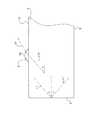
ところで、一般的な導光板では、図6に示すように導光板2に入射した光は、屈折角γが0≦|γ|≦sin-1(1/n)の式を満たす範囲で導光板2内に進み、例えば一般の導光板2に使用されている樹脂材料であるアクリル樹脂の屈折率はn=1.49程度であるので、光源に一番近い入射端面部3では、入射角が0°で入射端面部3の反対側の面(反射端面部)方向に屈折せずに進み(この光線のエネルギ値が一番高い)、また表面部5や裏面部6に近い場所での入射角も同様に0°に近い角度で入射する。
【0006】
さらに最大入射角は、図示しないリフレクタ等により反射散乱された光が入射端面部3の表面部5方向から裏面部6方向への光および裏面部6方向から表面部5方向への光が入射角90°となり、入射端面部3で屈折する屈折角γはγ=±42°程度の範囲内になる。
但し、表面部5近傍では裏面部6方向のみのγ=−42°のみ、裏面部6近傍では表面部5方向のみのγ=+42°のみとなる。
【0007】
また、屈折角γ=±42°の範囲内で導光板2内に入射した光は、導光板2と空気層(屈折率n=1)との境界面では、sinα=(1/n)の式により臨界角を表わすことができる。例えば一般の導光板2に使用されている樹脂材料であるアクリル樹脂の屈折率はn=1.49程度であるので臨界角αはα=42°程度になり、導光板2の表面部5や裏面部6に光線を乱す溝、凸や凹等が無ければ、導光板2内の光は表面部5や裏面部6で全て全反射しながら入射端面部3の反対側の面(反射端面部)方向へ進む。
【0008】
このように、入射端面部3での何れの場所でも屈折角γ=±42°の範囲内の光線が存在し、特に入射端面部3近傍に於ける表面部5方向や裏面部6方向等に向かう光線は、屈折角がγ=42°付近の光線であり、例えば、入射端面部3に近くエネルギ値が高い屈折角γ=42°の光線は、入射端面部3の表面部5側に近い所と裏面部6側に近い所であり、入射端面部3の表面部5側に近い所から入射した光線L1は、表面部5で全反射をして裏面部6に光線L2となって進み、裏面部6に設けた凸部40のドットパターンや図示しない散乱溝等によって全反射され、光線L2の入射角β1よりも出射角(反射角)β2の方が小さいために裏面部6で全反射し、光線L3となって表面部5に到達した光線は入射角が臨界角を破り表面部5から出射する。
【0009】
また、図示しないが裏面部6に設けた凸部40や図示しない散乱溝等によって屈折して導光板2の裏面部6の外に出射した光線は不図示の反射体により反射され、反射した光は再び導光板2に入射される。入射された光線は入射角度よりも小さい出射角度の場合には表面部5で臨界角を破り出射する。
【0010】
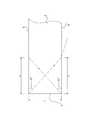
よって、表面部5や裏面部6に何らかの光線を乱す溝、凸や凹等の存在が無ければ全反射を続け、光線を乱す溝、凸や凹等の存在が有れば臨界角を破るリーク光やリークし得る光線となるが、入射端面部3側から最初にリーク光が出る範囲条件としては、図7で示すように、入射端面部3から表面部5方向への屈折角がγ=+42°の光線や入射端面部3から裏面部6方向への屈折角がγ=−42°の光線はcotγ*L=Xで得られ、入射端面部3からX離れた位置に進み、この位置に光線を乱す溝、凸や凹等の存在によって臨界角を破るリーク光が出射していまい、例えば、屈折角をγ=42°、導光板2の入射端面部3の厚さが2mm(ここでは裏面部6からの最大距離L)の場合に発生する輝線の位置はcot(42°)*2=2.22125となり、入射端面部から約2.22mm前後の位置に出現する。
【0011】
したがって、特開平8−240720号公報に開示される導光板において、着色ドットの印刷部の蛍光管の長軸方向と直角方向の幅が0.1mm〜2mmである場合には、0.22125mmズレてしまい、導光板の厚さによって臨界角を破るリーク光の位置が異なってしまう課題とともに入射端面部3側から最初に表面部5や裏面部6に向かう光線が導光板を透過して初めて光のエネルギを吸収することが出来るが、凸凹や散乱ドットパターン等の存在が無ければ全反射によりXの奇数倍の位置に存在するで凸凹や散乱ドットパターン等の存在によってリーク光の出射位置を左右してしまう課題がある。
【0012】
但し、入射端面部3からの距離X、輝線の出現する最大屈折角γの表面部5および裏面部6からの距離L、屈折角をγとする。
【0013】
さらに、入射端面部3と表面部5または裏面部6との成す傾きが6度以上の楔形導光板2の場合には、裏面部6が鏡面で凸凹や散乱ドットパターン等の存在が無くとも、π/2−最大屈折角γ(42°)−6°=42°以下となり、入射角度よりも小さい出射角度となって臨界角を破り表面部5から輝線となって上記の条件と一致した位置でリーク光が出現してしまう課題がある。
【0014】
また、やや重複するような説明になるが、平面照明装置に現れる輝線は、蛍光管等の線状光源と平行に現れるとともに輝線の線幅は1/10mm程度の細線であるために、輝線の発生する位置に対して光を吸収する着色印刷部等で輝線幅と同程度の幅で線を施したり、印刷や組み立て時に導光板との位置合わせの目的のために線を施すと光の吸収以上に暗線となって現れてしまう課題がある。
【0015】
さらに、例えば表面部5に凸凹や散乱ドットパターン等を設け、裏面部6に入射端面部3と直角方向に反射端面部4に延びるプリズムパターンを裏面部6に均一に施し、入射端面部3から入射し裏面部6方向に進んだ光線はプリズムによって集光されたエネルギの高い(高輝度)光線が裏面部6の下部にある反射体によって入射角と同角の反射角でプリズムに反射し、プリズム内に入った光線は各プリズムの入射側と反対方向の側面部7方向に進み表面部5に達して表面部5から出射するが、プリズムが側面部7に沿って多数並んでいるために表面部5から出射した高輝度の光線が輝線のように現れてしまう課題がある。
【0016】
また、従来の導光板として、例えば特開平8−327828号公報に開示されるものでは、光入射面の乗った平面に沿って延在する光遮蔽壁を設けて、導光板の入射端面部と表面部および裏面部との接続する部分を遮蔽材で覆う構成なので、直接光線を遮ってしまうため導光板内に入射する光量が減少し、光源からのエネルギの損失とともに遮蔽材の部品点数の増加や組み立て等の生産性等の課題がある。
【0017】
この発明は、このような課題を解決するためになされたもので、その目的は両面成形導光板の表面部や裏面部に屈折や反射を行う円弧状等の光制御部を設けるとともに表面部または裏面部に入射端面部から反射端面部に延びるプリズムが入射端面部に向かってプリズムの陵部を斜めに略三角平面状に切り取った部分の面積が大きくなるようにして輝線や暗線の出現を防止し、明るく均一な出射光を得ることのできる両面成形導光板および平面解明装置を提供することにある。
【0018】
【課題を解決するための手段】
前記課題を解決するため請求項1に係る導光板は、表面部に屈折を行う光制御部を設けるとともに裏面部に入射端面部から反射端面部に延びる凸状のプリズム部を略三角平面状に入射端面部に向かってプリズム部の頂から裏面部までプリズム部の陵部を斜めに切り取ることを特徴とする。
【0019】
請求項1に係る導光板は、表面部に屈折を行う光制御部を設けるとともに裏面部に入射端面部から反射端面部に延びる凸状のプリズム部を略三角平面状に入射端面部に向かってプリズム部の頂から裏面部までプリズム部の陵部を斜めに切り取るので、プリズムによる集光作用を小さくさせて外部に出射するとともに再度導光板に入射する外部からの光線に対し拡散効果が小さく、輝線の出現を防止できる。
【0020】
また、請求項2に係る導光板は、略三角平面状の部分を表面部または裏面部となす角度が0.095°〜11.3°の範囲であることを特徴と特徴とする。
【0021】
請求項2に係る導光板は、略三角平面状の部分を表面部または裏面部となす角度が0.095°〜11.3°の範囲であるので、導光板の大きさや厚さに左右されずにプリズムによる高輝度の輝線の発生を防止できる。
【0022】
さらに、請求項3に係る導光板は、光制御部を半径を5μm〜50μm、高さまたは深さを5μm〜50μm、曲率半径を10μm〜100μmである円弧状凸型または円弧状凹型もしくは最大投射長10μm〜100μm、高さまたは深さを5μm〜50μmである三角柱、四角柱および円柱の凸型または凹型であることをを特徴とする。
【0023】
請求項3に係る導光板は、光制御部の半径を5μm〜50μm、高さまたは深さを5μm〜50μm、曲率半径を10μm〜100μmである円弧状凸型または円弧状凹型もしくは最大投射長10μm〜100μm、高さまたは深さを5μm〜50μmである三角柱、四角柱および円柱の凸型または凹型であるので、入射端面部から導いた光源からの光線を目的に合った方向に出射することができるとともに線状光源からの出射光線を線状にせずに分散することができる。
【0024】
また、請求項4に係る導光板は、プリズムの幅を5μm〜1000μm、高さまたは深さを5μm〜1000μm、ピッチを5μm〜1000μmであることを特徴とする。
【0025】
請求項4に係る導光板は、プリズムの幅を5μm〜1000μm、高さまたは深さを5μm〜1000μm、ピッチを5μm〜1000μmであるので、導光板のサイズに伴ってプリズムの幅、ピッチおよび高さまたは深さをコントロールすることにより対向面に対して側面方向に広がりを持たせる光線を得ることができる。
【0026】
さらに、請求項5に係る平面照明装置は、光源と、当該光源からの光を導く入射端面部と入射端面部の反対側に位置する反射端面部と入射端面部から導いた光を出射する表面部と表面部の反対側に位置する裏面部と入射端面部と反射端面部とに接続する側面部とを有し表面部に屈折を行う凸型や凹型の光制御部を設けるとともに裏面部に入射端面部から反射端面部に廷びる凸状のプリズム部を略三角平面状に入射端面部に向かってプリズム部の頂から裏面部までプリズム部の陵部を斜めに切り取った両面成形導光板と、裏面部の下部に備えた反射体と、光源の光を反射し再び入射端面部に入射させるリフレクタとを具備したことを特徴とする。
【0027】
請求項5に係る平面照明装置は、光源と、当該光源からの光を導く入射端面部と入射端面部の反対側に位置する反射端面部と入射端面部から導いた光を出射する表面部と表面部の反対側に位置する裏面部と入射端面部と反射端面部とに接続する側面部とを有し表面部に屈折を行う凸型や凹型の光制御部を設けるとともに裏面部に入射端面部から反射端面部に廷びる凸状のプリズム部を略三角平面状に入射端面部に向かってプリズム部の頂から裏面部までプリズム部の陵部を斜めに切り取った両面成形導光板と、裏面部の下部に備えた反射体と、光源の光を反射し再び入射端面部に入射させるリフレクタとを具備したので、入射端面部から導いた光源からの光線を導光板のサイズに伴ってプリズムの幅、ピッチおよび高さまたは深さをコントロールすることにより対向面に対して側面方向に広がりを持たせ目的に合った方向に出射させるとともにプリズムの陵部を斜めに略三角平面状に切り取り入射端面部に近い程切り取部分の面積が大きくなるようにし、プリズムによる集光作用を小さくさせて線状光源からの出射光線を線状にせずに分散したり、反射体で反射した光線を再度導光板に入射する外部からの光線に対し拡散効果が小さいので、導光板の大きさや厚さに左右されずにプリズムによる高輝度の輝線の発生を防止することができる。
【0028】
【発明の実施の形態】
以下、本発明の実施の形態を添付図に基づいて説明する。
尚、本発明は、両面成形導光板の表面部や裏面部に屈折や反射を行う円弧状等の光制御部を設けるとともに表面部または裏面部に入射端面部から反射端面部に延びるプリズム部が入射端面部に向かってプリズムの陵部を斜めに略三角平面状に切り取った部分の面積が大きくなるようにして輝線や暗線の出現を防止し、明るく均一な出射光を得ることのできる導光板および平面照明装置を提供することにある。
【0029】
図1は本発明に係る平面照明装置の略斜視構成図、図2は導光板の入射端面部の拡大平面図、図3は本発明に係る平面照明装置のプリズム部の光線軌跡略図、図4は本発明に係る平面照明装置の入射端面部の光線軌跡略図、図5は本発明に係る平面照明装置のプリズム部の光線軌跡略図である。
【0030】
図1に示すように、本発明に係る平面照明装置1は、導光板2、光制御部8、反射体13、光源11およびリフレクタ12とを備えて構成されている。
【0031】
導光板2は、屈折率が1.4〜1.7程度の透明なアクリル樹脂(PMMA)やポリカーボネート(PC)等で成形され、光源10からの光を導く入射端面部3と、この入射端面部3と反対側に位置し光を導光板2内部に反射する反射端面部4と、これら入射端面部3と反射端面部4とに接続する側面部7と、光を出射する表面部5と、この表面部5と反対側に位置する裏面部6とからなる。
【0032】
また、導光板2は、表面部5に半径を5μm〜50μm、高さを5μm〜50μm、曲率半径を10μm〜100μmである円弧状凸型や半径を5μm〜50μm、高さまたは深さを5μm〜50μm、曲率半径を10μm〜100μmである円弧状凹型の光制御部8を施したり、最大投射長10μm〜100μm、高さを5μm〜50μmである三角柱、四角柱および円柱の凸型や最大投射長10μm〜100μm、深さを5μm〜50μmである三角柱、四角柱および円柱の凹型の光制御部8を施してある。
【0033】
光制御部8は、図2に示すように、例えば円弧状凸型において、入射端面部3から導光板内に屈折角γ=±42°(但し、導光板2に使用されている樹脂材料を屈折率はn=1.49程度のアクリル樹脂とする。)で入射した光線L1の中で表面部5方向に進んだ光線LR1は表面部5に施した円弧状凸型の光制御部8に進み、空気層との臨界面8aによって円弧状凸型の法線となす入射角(約20°)が臨界角よりも小さいために外部(空気層)に屈折して入射角よりも大きな出射角(約30.6°)で光線L0が出射する。
【0034】
また、図示しないが裏面部6に設けたプリズム9により屈折角γ=−42°によって裏面部6方向に進んだ光線が屈折して裏面部6の外部に出射され(全体としては集光される)、導光板2の下部に設けた反射体13によって反射された光線が再びプリズム9を透過し導光板2内に入射する。
【0035】
さらに、導光板2の裏面部6には、幅を5μm〜1000μm、高さまたは深さを5μm〜1000μm、ピッチを5μm〜1000μmのプリズム9を施して導光板のサイズに伴ってプリズム9の幅、ピッチおよび高さまたは深さをコントロールすることにより対向面に対して側面方向に広がりを持たせる光線を得るようにする。
【0036】
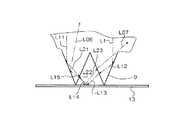
例えば、図3に示すように線光源11からの光を入射端面部3で屈折し屈折角γ=0〜−42°の平行光線L1が裏面部6に進みプリズム9と空気層との臨界面で入射角が臨界角よりも大きい(63°程度)ため、反射し光線L12となり、さらにプリズム9の対向面に進みプリズム9と空気層との臨界面で入射角が臨界角よりも小さい(16°程度)ため、プリズム面を透過した光線L13は、反射体13面に達して、この反射体13に対する入射角と等しい出射角で反射し、光線L14は再度、他方のプリズム面に進みプリズム9と空気層との臨界面で入射角が臨界角よりも小さいため、屈折して光線L15はプリズム9を透過して再びプリズム9面で空気層との臨界面で入射角が臨界角よりも大きく、反射して光線L06として表面部5方向に進む。
【0037】
また、同様に平行光線L11が裏面部6に進みプリズム9と空気層との臨界面で入射角が臨界角よりも大きいため、反射し光線L21となり、さらにプリズム9の対向面に進みプリズム9と空気層との臨界面で入射角が臨界角よりも小さいため、プリズム面を透過した光線L22は、反射体13面に達して、この反射体13に対する入射角と等しい出射角で反射し、光線L23は再度、他方のプリズム面に進みプリズム9と空気層との臨界面で入射角が臨界角よりも小さいため、屈折して光線L07として表面部5方向に進む。
【0038】
尚、これら光線L06や光線L07は、プリズム9の左右方向(導光板2の側面部7方向)に広がるようにプリズム9によって線光源11からの入射端面部3から反射端面部4方向に進む平行光線を表面部5に達するまでに側面部7方向に広がりをもたせることができる。
【0039】
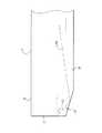
プリズム9は、図4に示すように、導光板2の入射端面部3に近い程大きく、裏面部6となす角度δが0.095°〜11.3°の範囲でプリズム9の陵部を斜めに切り取り、切り取った面が略三角平面状10(10a,10b)の形状になっている。これにより、入射端面部3での入射光は、屈折角γ=±42°の範囲のみの光となり、屈折角γ=0〜−42°の裏面部6方向に進んだ平行光線LSがプリズム9の陵部を斜めに切り取った略三角平面状10で空気層との臨界面で入射角が臨界角よりも大きい(65°程度)ため、略三角平面状10で反射し光線LS0となり、表面部5方向に進み、裏面部6の外部には漏れず、ましては入射端面部3付近の表面部5には出射しない。
【0040】
また、図5に入射端面部3からの略三角平面状10への視野図(プリズム部9の入射端面部3からの2箇所の断面図)を示す。
【0041】
プリズム9の陵部を斜めに切り取り、導光板2の入射端面部3に近い程略三角平面状10の底面部が大きくなる。屈折角γ=−42°で裏面部6方向に進んだ平行光線LS1は、プリズム9の1面に達し、空気層との臨界面で入射角が臨界角よりも大きい(72°程度)ため、1面で反射した光線LS11は略三角平面状10の底面部に進み、ここで光線LS11は空気層との臨界面で入射角が臨界角よりも小さいため、略三角平面状10の底面部を透過した光線LS12は、反射体13面に達し反射して表面部5方向に進むが、光線LS13は導光板2の側面部7方向に進むので入射端面部3付近の表面部5には輝線の発生が起こらない。
【0042】
同様に略三角平面状10の底面部が大きな場合には、屈折角γ=−42°で裏面部6方向に進んだ平行光線LS2は、プリズム9の1面に達し、空気層との臨界面で入射角が臨界角よりも大きいため、1面で反射した光線LS21は略三角平面状10の底面部に進み、ここで光線LS21は空気層との臨界面で入射角が臨界角よりも小さいため、略三角平面状10の底面部を透過した光線LS22は、反射体13面に達し反射して表面部5方向に進み光線LS13と同様に反射光線は導光板2の側面部7方向に進むので入射端面部3付近の表面部5には輝線の発生が起こらない。
【0043】
また、これら裏面部6方向に進む光線は、図4に示したように全体として図示しないが反射端面部4方向に進み、さらに説明したように反射光線は導光板2の側面部7方向に進むので入射端面部3付近の表面部5には輝線としての発生は無い。
【0044】
尚、図1では、入射端面部3と反射端面部4とに連続するプリズム部9の陵部を斜めに切り取って略三角平面状10(10a,10b)を形成したプリズム部9の形状を示しているが、導光板2内に進入した光線が、全て有効に表面部5に出射せずに反射端面部4方向に多くの光線が達するような場合は、入射端面部3側のみのプリズム部9の陵部を斜めに切り取って略三角平面状10(10a)としてもよい。また、導光板が長い場合や導光板の両端面(図1で言えば入射端面部3と反射端面部4)に対向して光源が配置される場合には、図1に示すようにプリズム部9の両端の陵部を斜めに切り取って略三角平面状10a,10bにするのが好ましい。
【0045】
光源11は、CFL(冷陰管)等の線状をなし、直接光は導光板2の入射端面部5から導光板2内に入射し、他の光はリフレクタ12で反射されながら光源11とリフレクタ13との空間を通って導光板2内に入射する。
【0046】
リフレクタ12は、白色の絶縁性材料やアルミニウム等の金属を蒸着したシート状または金属等からなり、導光板2の入射端面部5と光源11とを包囲するようにし、光源11からの光を反射し、反射光を導光板2の入射端面部5に再び入射させる。
【0047】
反射体13は、熱可塑性樹脂に例えば酸化チタンのような白色材料を混入したシートや熱可塑性樹脂のシートにアルミニウム等の金属蒸着を施したり、金属箔を積層した物やシート状金属からなり、入射端面部5と表面部5以外の部分を覆い光源11からの光が導光板2によって表面部5に出射した以外の光を反射し、再び導光板2に入射させて光源11からの光を全て表面部5から出射するようにする。
【0048】
このように、本発明の両面成形導光板および平面照明装置は、両面成形導光板の表面部や裏面部に屈折や反射を行う半径を5μm〜50μm、高さまたは深さを5μm〜50μm、曲率半径を10μm〜100μmである円弧状凸型または円弧状凹型もしくは最大投射長10μm〜100μm、高さまたは深さを5μm〜50μmである三角柱、四角柱および円柱の凸型または凹型の円弧状等の光制御部を設けるとともに表面部または裏面部に入射端面部から反射端面部に延びるプリズムの幅を5μm〜1000μm、高さまたは深さを5μm〜1000μm、ピッチを5μm〜1000μmとするプリズムが入射端面部に向かってプリズムの陵部を裏面部となす角度が0.095°〜11.3°の範囲に斜めに略三角平面状に切り取った部分の面積が大きくなるようにして輝線や暗線の出現を防止し、明るく均一な出射光を得る。
【0049】
【発明の効果】
以上のように、請求項1に係る導光板は、表面部に屈折を行う光制御部を設けるとともに裏面部に入射端面部から反射端面部に延びる凸状のプリズム部を略三角平面状に入射端面部に向かってプリズム部の頂から裏面部までプリズム部の陵部を斜めに切り取るので、プリズムによる集光作用を小さくさせて外部に出射するとともに再度導光板に入射する外部からの光線に対し拡散効果が小さく、輝線の出現を防止できて目に優しく見やすい平面光源を得ることができる。
【0050】
また、請求項2に係る導光板は、略三角平面状の部分を表面部または裏面部となす角度が0.095°〜11.3°の範囲であるので、導光板の大きさや厚さに左右されずにプリズムによる高輝度の輝線の発生を防止でき、あらゆる導光板や平面照明装置等の設計が容易にできる。
【0051】
さらに、請求項3に係る導光板は、光制御部の半径を5μm〜50μm、高さまたは深さを5μm〜50μm、曲率半径を10μm〜100μmである円弧状凸型または円弧状凹型もしくは最大投射長10μm〜100μm、高さまたは深さを5μm〜50μmである三角柱、四角柱および円柱の凸型または凹型であるので、入射端面部から導いた光源からの光線を目的に合った方向に出射することができるとともに線状光源からの出射光線を線状にせずに分散することができ、見やすく明るい導光板を得ることができる。
【0052】
また、請求項4に係る導光板は、プリズムの幅を5μm〜1000μm、高さまたは深さを5μm〜1000μm、ピッチを5μm〜1000μmであるので、導光板のサイズに伴ってプリズムの幅、ピッチおよび高さまたは深さをコントロールすることにより対向面に対して側面方向に広がりを持たせる光線を得ることができるので、光制御部による反射端面部方向や入射端面部方向に光線を制御することにより導光板全体として視野角の広がりの有る出射光を得ることができる。
【0053】
さらにまた、請求項5に係る平面照明装置は、光源と、当該光源からの光を導く入射端面部と入射端面部の反対側に位置する反射端面部と入射端面部から導いた光を出射する表面部と表面部の反対側に位置する裏面部と入射端面部と反射端面部とに接続する側面部とを有し表面部に屈折を行う凸型や凹型の光制御部を設けるとともに裏面部に入射端面部から反射端面部に廷びる凸状のプリズム部を略三角平面状に入射端面部に向かってプリズム部の頂から裏面部までプリズム部の陵部を斜めに切り取った両面成形導光板と、裏面部の下部に備えた反射体と、光源の光を反射し再び入射端面部に入射させるリフレクタとを具備したので、入射端面部から導いた光源からの光線を導光板のサイズに伴ってプリズムの幅、ピッチおよび高さまたは深さをコントロールすることにより対向面に対して側面方向に広がりを持たせ目的に合った方向に出射させるとともにプリズムの陵部を斜めに略三角平面状に切り取り入射端面部に近い程切り取部分の面積が大きくなるようにし、プリズムによる集光作用を小さくさせて線状光源からの出射光線を線状にせずに分散したり、反射体で反射した光線を再度導光板に入射する外部からの光線に対し拡散効果が小さいので、導光板の大きさや厚さに左右されずにプリズムによる高輝度の輝線の発生を防止することができ、カーナビのような小型で高輝度な物やモニタのような広視野角の必要な物まで各種に対応できる。
【図面の簡単な説明】
【図1】本発明に係る平面照明装置の略斜視横成図
【図2】本発明に係る平面照明装置の入射端面部の拡大平面図
【図3】本発明に係る平面照明装置のプリズム部の光線軌跡略図
【図4】本発明に係る平面照明装置の入射端面部の光線軌跡略図
【図5】本発明に係る平面照明装置のプリズム部の光線軌跡略図
【図6】従来の導光板の光線軌跡略図
【図7】従来の導光板の光線軌跡略図
【符号の説明】
1…平面照明装置、2…両面成形導光板、3…入射端面部、4…反射端面部、5…表面部、6…裏面部、7…側面部、8…光制御部、8a…臨界面、9…プリズム部、10(10a,10b)…略三角平面状、11…光源、12…リフレクタ、13…反射体、n…屈折率、γ…屈折角、δ…裏面部となす角度、L1,LR1,L0,L11,L06,L07,L21,L22,L15,L23,L12,L13,L14,L15,LS0,LS,LS1,LS2,LS11,LS12,LS13,LS21,LS22,L2,L3…光線、L…導光板の厚。40…凸部のドットパターン、β1…入射角、β2…出射角。[0001]
BACKGROUND OF THE INVENTION
The present invention relates to a double-sided light guide plate and a flat illumination device, and includes a light control unit such as an arc shape that performs refraction and reflection on a front surface portion and a back surface portion, and a reflection end surface from an incident end surface portion on the front surface portion or back surface portion. The prism part that extends to the entrance end face part increases the area of the part of the prism part that is obliquely cut into a substantially triangular plane to prevent the appearance of bright lines and dark lines, and bright and uniform outgoing light The present invention relates to a double-sided molded light guide plate and a plane elucidating device.
[0002]
[Prior art]
As a conventional light guide plate, for example, one disclosed in Japanese Patent Laid-Open No. 8-240720 is known. This light guide plate has a colored dot printing portion for absorbing light at the upper surface end of the reflector provided at the lower portion of the back surface portion of the light guide plate, and the colored dot printing portion is closer to the fluorescent tube. The area is gradually reduced from the distance to the far side, and the colored dots are gray, dark brown, purple, green, etc., and the colored dots are a plurality of straight lines that are almost parallel to the long axis direction of the fluorescent tube. The center points of a plurality of dots arranged in a straight line are substantially the same as the center points of a plurality of dots in a row adjacent to the row of dots arranged in a straight line. It is arranged at the middle point.
[0003]
As a conventional light guide plate, for example, one disclosed in JP-A-8-327828 is known. This light guide plate is provided by providing a light shielding wall extending along a plane on which a light incident surface rides, and covering a portion where the incident end surface portion of the light guide plate is connected to the front surface portion and the back surface portion with a shielding material. is there.
[0004]
[Problems to be solved by the invention]
As a conventional light guide plate, for example, what is disclosed in Japanese Patent Application Laid-Open No. 8-240720 has a colored dot printing portion for absorbing light at the upper end portion of a reflector provided at the lower portion of the back surface portion of the light guide plate. And have the colored dot printed part gradually decrease in area from the side closer to the fluorescent tube to the far side, or the colored dots are made of gray, dark brown, purple, green, etc., and further colored The dots are arranged in a plurality of straight lines substantially parallel to the major axis direction of the fluorescent tube, and the center points of the plurality of dots arranged in an arbitrary straight line are arranged on the plurality of dots arranged in an arbitrary straight line. In this configuration, the dots are arranged at approximately the midpoint between the center points of a plurality of dots in a row adjacent to the row.
[0005]
By the way, in a general light guide plate, as shown in FIG. 6, the light incident on the light guide plate 2 has a refraction angle γ of 0 ≦ | γ | ≦ sin.-1 Since the refractive index of the acrylic resin, which is a resin material used in the general light guide plate 2, is about n = 1.49, the light source goes into the light guide plate 2 within a range satisfying the expression (1 / n). In the incident end face part 3 closest to, the incident angle is 0 ° and the light does not refract in the direction opposite to the incident end face part 3 (reflection end face part) (the energy value of this light beam is the highest). Similarly, the incident angle near the
[0006]
Further, the maximum incident angle is such that light reflected and scattered by a reflector or the like (not shown) is incident light from the
However, only γ = −42 ° only in the direction of the back surface 6 in the vicinity of the
[0007]
Further, the light incident on the light guide plate 2 within the range of the refraction angle γ = ± 42 ° is expressed by sin α = (1 / n) at the boundary surface between the light guide plate 2 and the air layer (refractive index n = 1). The critical angle can be expressed by an equation. For example, since the refractive index of acrylic resin, which is a resin material used for a general light guide plate 2, is about n = 1.49, the critical angle α is about α = 42 °, and the
[0008]
Thus, there is a light beam in the range of the refraction angle γ = ± 42 ° at any location on the incident end face 3, and particularly in the direction of the
[0009]
Although not shown, the light beam refracted by the
[0010]
Therefore, if there is no groove, convex or concave, etc. that disturbs the light beam on the
[0011]
Therefore, in the light guide plate disclosed in Japanese Patent Application Laid-Open No. 8-240720, when the width of the printed portion of the colored dots in the direction perpendicular to the major axis direction of the fluorescent tube is 0.1 mm to 2 mm, the deviation is 0.22125 mm. As a result, the position of the leaked light that breaks the critical angle differs depending on the thickness of the light guide plate, and the light is first transmitted from the incident end surface portion 3 side toward the
[0012]
However, the distance X from the incident end face portion 3, the distance L from the
[0013]
Furthermore, in the case of the wedge-shaped light guide plate 2 having an inclination between the incident end face part 3 and the
[0014]
In addition, although the description is somewhat overlapping, the bright line appearing in the flat illumination device appears in parallel with a linear light source such as a fluorescent tube and the line width of the bright line is a thin line of about 1/10 mm. Absorbs light when a line is applied with the same width as the bright line width in a colored printing section that absorbs light at the generated position, or for alignment purposes with the light guide plate during printing or assembly. There is a problem that appears as a dark line.
[0015]
Further, for example, the
[0016]
Further, as a conventional light guide plate, for example, disclosed in JP-A-8-327828, a light shielding wall extending along a plane on which a light incident surface is placed is provided, and an incident end surface portion of the light guide plate is provided. Since the part that connects the front and back parts is covered with a shielding material, the amount of light entering the light guide plate is reduced because the light is directly blocked, and the number of parts of the shielding material increases along with the loss of energy from the light source. There are issues such as productivity such as assembly.
[0017]
The present invention has been made to solve such a problem. The purpose of the present invention is to provide an arc-shaped light control unit that performs refraction and reflection on the front surface and back surface of the double-sided light guide plate and Prevents the appearance of bright lines and dark lines by increasing the area of the prism that extends from the incident end face part to the reflective end face part on the back side by cutting the projecting part of the prism diagonally toward the incident end face part in a substantially triangular plane. It is another object of the present invention to provide a double-sided shaped light guide plate and a plane elucidating device capable of obtaining bright and uniform outgoing light.
[0018]
[Means for Solving the Problems]
In order to solve the above-mentioned problem, a light guide plate according to
[0019]
The light guide plate according to
[0020]
The light guide plate according to claim 2 is characterized in that the angle between the substantially triangular planar portion and the front surface portion or the back surface portion is in the range of 0.095 ° to 11.3 °.
[0021]
In the light guide plate according to claim 2, the angle between the substantially triangular planar portion and the front surface portion or the back surface portion is in the range of 0.095 ° to 11.3 °, and therefore depends on the size and thickness of the light guide plate. In addition, it is possible to prevent the generation of high-intensity bright lines due to the prism.
[0022]
The light guide plate according to claim 3 is an arc-shaped convex or arc-shaped concave or maximum projection having a radius of 5 μm to 50 μm, a height or depth of 5 μm to 50 μm, and a radius of curvature of 10 μm to 100 μm. It is characterized by being a convex or concave shape of a triangular prism, a quadrangular prism, and a cylinder having a length of 10 to 100 μm and a height or depth of 5 to 50 μm.
[0023]
The light guide plate according to claim 3 has an arcuate convex shape or an arcuate concave shape having a radius of the light control unit of 5 μm to 50 μm, a height or depth of 5 μm to 50 μm, a radius of curvature of 10 μm to 100 μm, or a maximum projection length of 10 μm. Because it is a convex shape or concave shape of a triangular prism, a quadrangular prism, and a cylinder having a height or depth of 5 μm to 50 μm, it can emit light from a light source guided from the incident end face in a direction that suits the purpose. In addition, the emitted light from the linear light source can be dispersed without being linear.
[0024]
The light guide plate according to claim 4 is characterized in that the prism has a width of 5 μm to 1000 μm, a height or depth of 5 μm to 1000 μm, and a pitch of 5 μm to 1000 μm.
[0025]
The light guide plate according to claim 4 has a prism width of 5 μm to 1000 μm, a height or depth of 5 μm to 1000 μm, and a pitch of 5 μm to 1000 μm. Therefore, the prism width, pitch and height are increased according to the size of the light guide plate. By controlling the depth or depth, it is possible to obtain a light beam that expands in the lateral direction with respect to the opposing surface.
[0026]
Further, the flat illumination device according to
[0027]
The flat illumination device according to
[0028]
DETAILED DESCRIPTION OF THE INVENTION
Hereinafter, embodiments of the present invention will be described with reference to the accompanying drawings.
In the present invention, an arc-shaped light control unit that performs refraction and reflection is provided on the front surface and the back surface of the double-sided light guide plate, and a prism portion extending from the incident end surface to the reflection end surface is provided on the front or back surface. A light guide plate capable of obtaining bright and uniform emitted light by preventing the appearance of bright lines and dark lines by increasing the area of the portion obtained by obliquely cutting the ridge portion of the prism toward the incident end face portion into a substantially triangular plane. And providing a flat illumination device.
[0029]
1 is a schematic perspective view of a flat illumination device according to the present invention, FIG. 2 is an enlarged plan view of an incident end surface portion of a light guide plate, and FIG. 3 is a schematic diagram of a ray locus of a prism portion of the flat illumination device according to the present invention. FIG. 5 is a schematic diagram of the ray trajectory of the incident end face of the flat illumination device according to the present invention, and FIG. 5 is a schematic diagram of the ray trace of the prism portion of the flat illumination device according to the present invention.
[0030]
As shown in FIG. 1, the
[0031]
The light guide plate 2 is formed of a transparent acrylic resin (PMMA) or polycarbonate (PC) having a refractive index of about 1.4 to 1.7, and includes an incident end face portion 3 that guides light from the
[0032]
The light guide plate 2 has an arcuate convex shape with a radius of 5 μm to 50 μm, a height of 5 μm to 50 μm, a radius of curvature of 10 μm to 100 μm, a radius of 5 μm to 50 μm, and a height or depth of 5 μm on the
[0033]
As shown in FIG. 2, the
[0034]
Although not shown, the
[0035]
Further, a
[0036]
For example, as shown in FIG. 3, the light from the line light source 11 is refracted at the incident end face 3 and the parallel light beam L1 having a refraction angle γ = 0 to −42 ° proceeds to the back face 6 and the critical surface between the
[0037]
Similarly, the parallel light beam L11 travels to the back surface 6 and the incident angle is larger than the critical angle at the critical surface of the
[0038]
The light rays L06 and L07 are parallelly traveled by the
[0039]
As shown in FIG. 4, the
[0040]
Further, FIG. 5 shows a field view (two cross-sectional views from the incident end surface portion 3 of the prism portion 9) from the incident end surface portion 3 to the substantially triangular
[0041]
The bottom portion of the substantially triangular
[0042]
Similarly, when the bottom surface portion of the substantially triangular
[0043]
Further, the light rays traveling in the direction of the back surface portion 6 proceed in the direction of the reflection end surface portion 4 although not shown as a whole as shown in FIG. 4, and the reflected light beams proceed in the direction of the side surface portion 7 of the light guide plate 2 as further described. Therefore, there is no generation of bright lines on the
[0044]
In FIG. 1, the shape of the
[0045]
The light source 11 has a linear shape such as a CFL (cold cathode tube), and direct light enters the light guide plate 2 from the incident
[0046]
The
[0047]
The
[0048]
As described above, the double-sided light guide plate and the flat illumination device of the present invention have a radius of 5 μm to 50 μm, a height or a depth of 5 μm to 50 μm, and a curvature that refracts or reflects on the front surface or the back surface of the double-sided light guide plate. An arcuate convex shape or arcuate concave shape having a radius of 10 μm to 100 μm, or a triangular column, a quadrangular column and a cylindrical convex or concave arc shape having a maximum projection length of 10 μm to 100 μm and a height or depth of 5 μm to 50 μm, etc. A prism having a light control portion and a prism extending from the incident end surface portion to the reflecting end surface portion on the front surface portion or the rear surface portion, having a width of 5 μm to 1000 μm, a height or depth of 5 μm to 1000 μm, and a pitch of 5 μm to 1000 μm. The area of the portion that is obliquely cut out in a substantially triangular plane within the range of 0.095 ° to 11.3 °, the angle between the ridge portion of the prism and the back surface portion, is large. Preventing the appearance of bright lines and dark lines in the Kunar so, obtain a bright uniform emitted light.
[0049]
【The invention's effect】
As described above, the light guide plate according to
[0050]
In addition, the light guide plate according to claim 2 has an angle between the surface portion or the back surface portion of the substantially triangular planar portion in the range of 0.095 ° to 11.3 °. It is possible to prevent the generation of high-brightness bright lines by the prism without being influenced, and it is possible to easily design all light guide plates and flat illumination devices.
[0051]
The light guide plate according to claim 3 is an arc-shaped convex or arc-shaped concave or maximum projection having a radius of the light control unit of 5 μm to 50 μm, a height or depth of 5 μm to 50 μm, and a radius of curvature of 10 μm to 100 μm. Since it is a convex or concave shape of a triangular prism, a quadrangular prism, and a cylinder having a length of 10 to 100 μm and a height or depth of 5 to 50 μm, it emits light from a light source guided from the incident end face in a direction suitable for the purpose. In addition, the light emitted from the linear light source can be dispersed without being linear, and a light guide plate that is easy to see and bright can be obtained.
[0052]
The light guide plate according to claim 4 has a prism width of 5 μm to 1000 μm, a height or depth of 5 μm to 1000 μm, and a pitch of 5 μm to 1000 μm. By controlling the height or depth, it is possible to obtain a light beam that expands in the lateral direction with respect to the opposing surface, so that the light control unit controls the light beam in the direction of the reflection end surface or the incident end surface. As a result, it is possible to obtain outgoing light having a wide viewing angle as the entire light guide plate.
[0053]
Furthermore, the flat illumination device according to
[Brief description of the drawings]
FIG. 1 is a schematic perspective horizontal view of a flat illumination device according to the present invention.
FIG. 2 is an enlarged plan view of an incident end surface portion of the flat illumination device according to the present invention.
FIG. 3 is a schematic diagram of a ray locus of a prism portion of the flat illumination device according to the present invention.
FIG. 4 is a schematic diagram of the ray trajectory of the incident end face portion of the flat illumination device according to the present invention.
FIG. 5 is a schematic diagram of the ray trajectory of the prism portion of the flat illumination device according to the present invention.
FIG. 6 is a schematic diagram of a ray trajectory of a conventional light guide plate.
FIG. 7 is a schematic diagram of a ray locus of a conventional light guide plate.
[Explanation of symbols]
DESCRIPTION OF
Claims (5)
Translated fromJapanesePriority Applications (1)
| Application Number | Priority Date | Filing Date | Title |
|---|---|---|---|
| JP2000325782AJP4460141B2 (en) | 2000-10-25 | 2000-10-25 | Double-sided light guide plate and flat illumination device |
Applications Claiming Priority (1)
| Application Number | Priority Date | Filing Date | Title |
|---|---|---|---|
| JP2000325782AJP4460141B2 (en) | 2000-10-25 | 2000-10-25 | Double-sided light guide plate and flat illumination device |
Publications (2)
| Publication Number | Publication Date |
|---|---|
| JP2002133930A JP2002133930A (en) | 2002-05-10 |
| JP4460141B2true JP4460141B2 (en) | 2010-05-12 |
Family
ID=18803087
Family Applications (1)
| Application Number | Title | Priority Date | Filing Date |
|---|---|---|---|
| JP2000325782AExpired - Fee RelatedJP4460141B2 (en) | 2000-10-25 | 2000-10-25 | Double-sided light guide plate and flat illumination device |
Country Status (1)
| Country | Link |
|---|---|
| JP (1) | JP4460141B2 (en) |
Families Citing this family (15)
| Publication number | Priority date | Publication date | Assignee | Title |
|---|---|---|---|---|
| KR20030091194A (en)* | 2002-05-24 | 2003-12-03 | 주식회사 릿츠 | Display and back-light unit for display |
| TW200527016A (en)* | 2004-01-26 | 2005-08-16 | Zeon Corp | Light guide plate and backlight |
| WO2006080216A1 (en)* | 2005-01-26 | 2006-08-03 | Sumitomo Electric Industries, Ltd. | Surface emitting device |
| JP4849335B2 (en)* | 2006-01-31 | 2012-01-11 | コニカミノルタオプト株式会社 | Light guide, backlight device and light source device |
| JP5315613B2 (en)* | 2006-01-31 | 2013-10-16 | コニカミノルタ株式会社 | Light guide plate and backlight device |
| TW200739138A (en)* | 2006-03-17 | 2007-10-16 | Mitsubishi Rayon Co | Prism sheet, planar light source device and method for manufacturing the prism sheet |
| JP2010510546A (en) | 2006-11-15 | 2010-04-02 | スリーエム イノベイティブ プロパティズ カンパニー | Backlight display with high illumination uniformity |
| US7766528B2 (en) | 2006-11-15 | 2010-08-03 | 3M Innovative Properties Company | Back-lit displays with high illumination uniformity |
| US7789538B2 (en) | 2006-11-15 | 2010-09-07 | 3M Innovative Properties Company | Back-lit displays with high illumination uniformity |
| US7478913B2 (en) | 2006-11-15 | 2009-01-20 | 3M Innovative Properties | Back-lit displays with high illumination uniformity |
| JP5585806B2 (en)* | 2008-07-22 | 2014-09-10 | 三菱レイヨン株式会社 | Surface light source device and light guide used therefor |
| US8960977B2 (en) | 2012-08-10 | 2015-02-24 | Lg Innotek Co., Ltd. | Illuminating device |
| EP2696135B1 (en)* | 2012-08-10 | 2019-11-27 | LG Innotek Co., Ltd. | Lighting device |
| CN104121516B (en) | 2014-07-11 | 2016-08-17 | 京东方科技集团股份有限公司 | Lamp holder and desk lamp for desk lamp |
| CN113759596B (en)* | 2020-06-05 | 2025-02-11 | 瑞仪光电(苏州)有限公司 | Light guide plate, backlight module and display device |
- 2000
- 2000-10-25JPJP2000325782Apatent/JP4460141B2/ennot_activeExpired - Fee Related
Also Published As
| Publication number | Publication date |
|---|---|
| JP2002133930A (en) | 2002-05-10 |
Similar Documents
| Publication | Publication Date | Title |
|---|---|---|
| US6174064B1 (en) | Light guide panel and plane illuminator apparatus | |
| JP4460141B2 (en) | Double-sided light guide plate and flat illumination device | |
| KR100678850B1 (en) | Surface light source device, diffuser plate and liquid crystal display device | |
| KR100535191B1 (en) | Optical waveguide sheet, surface illuminant device and liquid crystal display | |
| US7918597B2 (en) | Spread illuminating apparatus | |
| US6678021B2 (en) | Light guide plate, surface light source device and liquid crystal display | |
| JP5267531B2 (en) | Light guide panel | |
| JP4588729B2 (en) | Flat lighting device | |
| JPH09145932A (en) | Back light and optical sheet | |
| JP2001014921A (en) | Surface lighting system | |
| JP2005085671A (en) | Light guide plate and plane light source device | |
| KR100786384B1 (en) | Back light assembly of the liquid crystal display device provided with the optical sheet and the optical sheet | |
| JP4243635B2 (en) | Lighting device | |
| JPH08304607A (en) | Backlight | |
| JP2007200768A (en) | Light guide plate and flat illumination device | |
| JP4436845B2 (en) | Light guide plate | |
| JP3875362B2 (en) | Light guide plate and flat illumination device | |
| JP4324133B2 (en) | Light guide plate and flat illumination device | |
| JP3883121B2 (en) | Lighting device | |
| JP2006202639A5 (en) | ||
| JP2006202639A (en) | Backlight device | |
| JP3338800B2 (en) | Flat lighting device | |
| JP3160594B2 (en) | Light guide plate and flat lighting device | |
| JP2001124930A (en) | Light transmission plate and planar illuminator | |
| JP3696095B2 (en) | Illumination device and display device |
Legal Events
| Date | Code | Title | Description |
|---|---|---|---|
| A621 | Written request for application examination | Free format text:JAPANESE INTERMEDIATE CODE: A621 Effective date:20070817 | |
| A977 | Report on retrieval | Free format text:JAPANESE INTERMEDIATE CODE: A971007 Effective date:20090714 | |
| A131 | Notification of reasons for refusal | Free format text:JAPANESE INTERMEDIATE CODE: A131 Effective date:20090728 | |
| A521 | Written amendment | Free format text:JAPANESE INTERMEDIATE CODE: A523 Effective date:20090918 | |
| TRDD | Decision of grant or rejection written | ||
| A01 | Written decision to grant a patent or to grant a registration (utility model) | Free format text:JAPANESE INTERMEDIATE CODE: A01 Effective date:20100112 | |
| A01 | Written decision to grant a patent or to grant a registration (utility model) | Free format text:JAPANESE INTERMEDIATE CODE: A01 | |
| A61 | First payment of annual fees (during grant procedure) | Free format text:JAPANESE INTERMEDIATE CODE: A61 Effective date:20100212 | |
| R150 | Certificate of patent or registration of utility model | Ref document number:4460141 Country of ref document:JP Free format text:JAPANESE INTERMEDIATE CODE: R150 Free format text:JAPANESE INTERMEDIATE CODE: R150 | |
| FPAY | Renewal fee payment (event date is renewal date of database) | Free format text:PAYMENT UNTIL: 20130219 Year of fee payment:3 | |
| FPAY | Renewal fee payment (event date is renewal date of database) | Free format text:PAYMENT UNTIL: 20130219 Year of fee payment:3 | |
| S111 | Request for change of ownership or part of ownership | Free format text:JAPANESE INTERMEDIATE CODE: R313113 | |
| FPAY | Renewal fee payment (event date is renewal date of database) | Free format text:PAYMENT UNTIL: 20130219 Year of fee payment:3 | |
| R360 | Written notification for declining of transfer of rights | Free format text:JAPANESE INTERMEDIATE CODE: R360 | |
| FPAY | Renewal fee payment (event date is renewal date of database) | Free format text:PAYMENT UNTIL: 20130219 Year of fee payment:3 | |
| R360 | Written notification for declining of transfer of rights | Free format text:JAPANESE INTERMEDIATE CODE: R360 | |
| R371 | Transfer withdrawn | Free format text:JAPANESE INTERMEDIATE CODE: R371 | |
| FPAY | Renewal fee payment (event date is renewal date of database) | Free format text:PAYMENT UNTIL: 20130219 Year of fee payment:3 | |
| S111 | Request for change of ownership or part of ownership | Free format text:JAPANESE INTERMEDIATE CODE: R313113 | |
| FPAY | Renewal fee payment (event date is renewal date of database) | Free format text:PAYMENT UNTIL: 20130219 Year of fee payment:3 | |
| R350 | Written notification of registration of transfer | Free format text:JAPANESE INTERMEDIATE CODE: R350 | |
| FPAY | Renewal fee payment (event date is renewal date of database) | Free format text:PAYMENT UNTIL: 20160219 Year of fee payment:6 | |
| R250 | Receipt of annual fees | Free format text:JAPANESE INTERMEDIATE CODE: R250 | |
| S111 | Request for change of ownership or part of ownership | Free format text:JAPANESE INTERMEDIATE CODE: R313113 | |
| R360 | Written notification for declining of transfer of rights | Free format text:JAPANESE INTERMEDIATE CODE: R360 | |
| R360 | Written notification for declining of transfer of rights | Free format text:JAPANESE INTERMEDIATE CODE: R360 | |
| R371 | Transfer withdrawn | Free format text:JAPANESE INTERMEDIATE CODE: R371 | |
| S111 | Request for change of ownership or part of ownership | Free format text:JAPANESE INTERMEDIATE CODE: R313113 | |
| S531 | Written request for registration of change of domicile | Free format text:JAPANESE INTERMEDIATE CODE: R313531 | |
| R350 | Written notification of registration of transfer | Free format text:JAPANESE INTERMEDIATE CODE: R350 | |
| R250 | Receipt of annual fees | Free format text:JAPANESE INTERMEDIATE CODE: R250 | |
| R250 | Receipt of annual fees | Free format text:JAPANESE INTERMEDIATE CODE: R250 | |
| R250 | Receipt of annual fees | Free format text:JAPANESE INTERMEDIATE CODE: R250 | |
| R250 | Receipt of annual fees | Free format text:JAPANESE INTERMEDIATE CODE: R250 | |
| LAPS | Cancellation because of no payment of annual fees |