JP4458539B2 - Optical cable connector - Google Patents
Optical cable connectorDownload PDFInfo
- Publication number
- JP4458539B2 JP4458539B2JP2005263108AJP2005263108AJP4458539B2JP 4458539 B2JP4458539 B2JP 4458539B2JP 2005263108 AJP2005263108 AJP 2005263108AJP 2005263108 AJP2005263108 AJP 2005263108AJP 4458539 B2JP4458539 B2JP 4458539B2
- Authority
- JP
- Japan
- Prior art keywords
- optical
- cable
- optical drop
- housing
- drop cable
- Prior art date
- Legal status (The legal status is an assumption and is not a legal conclusion. Google has not performed a legal analysis and makes no representation as to the accuracy of the status listed.)
- Expired - Fee Related
Links
- 230000003287optical effectEffects0.000titleclaimsdescription381
- 239000013307optical fiberSubstances0.000claimsdescription50
- 210000000078clawAnatomy0.000claimsdescription33
- 238000003780insertionMethods0.000claimsdescription33
- 230000037431insertionEffects0.000claimsdescription33
- 239000011248coating agentSubstances0.000claimsdescription21
- 238000000576coating methodMethods0.000claimsdescription21
- 239000000835fiberSubstances0.000claimsdescription21
- 230000001681protective effectEffects0.000claimsdescription15
- 239000002184metalSubstances0.000claimsdescription7
- 230000002093peripheral effectEffects0.000claimsdescription5
- 230000008878couplingEffects0.000claimsdescription4
- 238000010168coupling processMethods0.000claimsdescription4
- 238000005859coupling reactionMethods0.000claimsdescription4
- 230000004308accommodationEffects0.000claimsdescription2
- 238000000034methodMethods0.000description6
- 238000009434installationMethods0.000description4
- 125000006850spacer groupChemical group0.000description3
- 229920002430Fibre-reinforced plasticPolymers0.000description2
- 239000011151fibre-reinforced plasticSubstances0.000description2
- 229910000831SteelInorganic materials0.000description1
- 230000000694effectsEffects0.000description1
- 230000004927fusionEffects0.000description1
- 239000010959steelSubstances0.000description1
- 239000002699waste materialSubstances0.000description1
- 239000002023woodSubstances0.000description1
Images


Landscapes
- Mechanical Coupling Of Light Guides (AREA)
- Light Guides In General And Applications Therefor (AREA)
Description
Translated fromJapanese本発明は、光ケーブル接続具に関し、特に、建物外から建物内に引き込まれた光ドロップケーブルと建物内に敷設された光ドロップケーブルとを建物内で接続するのに好適な光ケーブル接続具に関する。 The present invention relates to an optical cable connector, and more particularly to an optical cable connector suitable for connecting an optical drop cable drawn into the building from outside the building and an optical drop cable laid in the building in the building.
インターネットの普及に伴い、光ファイバを用いて高速かつ大容量の信号を各家庭やオフィスなどへ伝送することができるFTTH(Fiber To The Home)が注目されている。光ファイバを各家庭やオフィスなどの建物まで敷設する方法としては、従来のメタル電話線と同様に架空線路を利用して、多芯光ケーブルを敷設する方法が主流である。架空線路から建物までは、引落し用クロージャを介して1芯または2芯の光ドロップケーブルを接続することによって、多芯光ケーブルを分配している。 With the spread of the Internet, FTTH (Fiber To The Home) that can transmit a high-speed and large-capacity signal to each home or office using an optical fiber has attracted attention. As a method of laying an optical fiber to a building such as each home or office, a method of laying a multi-core optical cable using an overhead line as in the case of a conventional metal telephone line is the mainstream. The multi-core optical cable is distributed from the overhead line to the building by connecting a one-core or two-core optical drop cable via a drop closure.
従来、引落し用クロージャからの光ドロップケーブルと建物内に敷設された光ドロップケーブルとの接続は、建物外に設置された接続部を用いて行われている。
たとえば、下記の特許文献1および特許文献2には、小型かつ軽量でありかつ設置場所の制約を少なくするために、光ファイバと支持線とをそれぞれ備えた2本の光ドロップケーブルの端末同士を接続する光ドロップケーブルの接続部において、双方の光ドロップケーブルの端末からそれぞれ露出された光ファイバの端末同士が直接接続され、直接接続されたそれぞれの光ファイバの端末に弛みが生じるように、双方の光ドロップケーブルの支持線の端末同士が直線的に連結されている、光ドロップケーブルの接続部が開示されている。Conventionally, the connection between the optical drop cable from the drop closure and the optical drop cable laid in the building is performed using a connecting portion installed outside the building.
For example, in Patent Document 1 and Patent Document 2 below, two optical drop cable terminals each having an optical fiber and a support line are provided in order to reduce the size and weight, and to reduce the restrictions on the installation location. In the connecting part of the optical drop cable to be connected, both ends of the optical fibers exposed from the ends of both optical drop cables are directly connected to each other, and both ends of the optical fibers connected directly are slackened. The connection part of the optical drop cable by which the terminal of the support line of this optical drop cable is connected linearly is disclosed.
また、光ドロップケーブルは、ユーザの変更、建物の変更、あるいは架空線路の変更が生じると、再敷設および撤去される。このことは、光ドロップケーブルの無駄を生じさせてしまう。
そこで、下記の特許文献3には、たとえば光ドロップケーブルの長さが不足したような場合であっても光ドロップケーブルの継ぎ足しが容易に行えて光ドロップケーブルの再敷設などが不要となるようにするために、少なくとも一対の光ファイバケーブルの被覆部を固定する2つのケーブル固定部と、2つのケーブル固定部との間に光ファイバの接続部を固定する接続部固定部とを有する光ファイバケーブル接続用スペーサが開示されている。
Therefore, in Patent Document 3 below, for example, even when the length of the optical drop cable is insufficient, it is possible to easily add the optical drop cable so that re-laying of the optical drop cable is unnecessary. An optical fiber cable having two cable fixing portions for fixing at least a pair of optical fiber cable covering portions and a connection portion fixing portion for fixing an optical fiber connection portion between the two cable fixing portions. A connection spacer is disclosed.
しかしながら、上述した特許文献1および特許文献2に開示された光ドロップケーブルの接続部は、加入者用光ファイバケーブルと加入者宅間の架空区間で張力を担う支持線を利用するものであるので、十分な引張強度を持たせて光ドロップケーブル同士を建物外で接続するのには有効であるかもしれないが、支持線は光ドロップケーブルを建物内に引き込む際には切断されるため、十分な引張強度を持たせて光ドロップケーブル同士を建物内で接続するのには有効ではない。
また、上述した特許文献3に開示された光ファイバケーブル接続用スペーサは、光ドロップケーブルの継ぎ足しを容易に行って光ドロップケーブルの再敷設などを不要にするためには有効であるかもしれないが、たとえば建物内に引き込まれている光ドロップケーブルを補修する場合には、このような光ファイバケーブル接続用スペーサを用いて建物外で光ドロップケーブル同士を接続するよりも、建物内で光ドロップケーブル同士を接続した方が、作業性の向上が図れる。However, since the connection part of the optical drop cable disclosed in Patent Document 1 and Patent Document 2 described above uses a support line that bears tension in an aerial section between the subscriber optical fiber cable and the subscriber's house, Although it may be effective to connect optical drop cables outside the building with sufficient tensile strength, the support line is cut when the optical drop cable is pulled into the building, so it is sufficient It is not effective for connecting optical drop cables in a building with tensile strength.
In addition, the optical fiber cable connection spacer disclosed in Patent Document 3 described above may be effective for easily adding an optical drop cable and eliminating the need for re-laying the optical drop cable. For example, when repairing an optical drop cable drawn into a building, the optical drop cable is used inside the building rather than connecting the optical drop cables outside the building using such an optical fiber cable connection spacer. The workability can be improved by connecting them together.
本発明の目的は、十分な引張強度を持たせた光ドロップケーブル同士の接続を建物内で行うことができる光ケーブル接続具を提供することにある。 An object of the present invention is to provide an optical cable connector that can connect optical drop cables having sufficient tensile strength in a building.
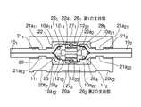
本発明の光ケーブル接続具は、建物外から建物内に引き込まれた第1の光ドロップケーブル(101)と建物内に敷設された第2の光ドロップケーブル(102)とを建物内で接続するための光ケーブル接続具であって、前記第1および第2の光ドロップケーブルを接続した状態で固定するためのハウジング(20)と、第1および第2の光ドロップケーブル固定手段とを具備し、前記ハウジングの上面に、前記第1および第2の光ドロップケーブルをそれぞれ収容するための第1および第2のケーブル収容溝(211,212)が、該ハウジングの両端部から該ハウジングの中央部に向かって延びてそれぞれ形成されており、前記第1および第2のケーブル収容溝の間の領域に、前記第1の光ドロップケーブルの第1の被覆(131)を該第1の光ドロップケーブルの幅方向中央部で長手方向に沿って所定の長さだけ切り開いて該第1の光ドロップケーブルの先端部を2つの先端部分(10a11,10a12)に分岐させることによって露出された第1の光ファイバ心線(111)と、前記第2の光ドロップケーブルの第2の被覆(132)を該第2の光ドロップケーブルの幅方向中央部で長手方向に沿って所定の長さだけ切り開いて該第2の光ドロップケーブルの先端部を2つの先端部分(10a21,10a22)に分岐させることによって露出された第2の光ファイバ心線(112)とを接続するためのファイバ連結部(22)が前記ハウジングの上面の凹部として形成されており、前記ファイバ連結部に、前記第1および第2の光ファイバ心線を接続する光ファイバ心線接続手段を該光ファイバ心線接続手段の幅方向両側から保持する第1および第2の保持爪(22a1,22a2)が設けられており、前記第1の光ドロップケーブル固定手段が、前記ファイバ連結部の前記光ファイバ心線接続手段の幅方向両側の一方側に設けられているとともに、前記第1の光ドロップケーブルのテンションメンバ(1211,1212)および第1の被覆(131)を含む前記2つの先端部分(10a11,10a12)のうちの一方(10a11)の第1の被覆(131)を取り除くことにより露出されたテンションメンバ(1211)と前記第2の光ドロップケーブルのテンションメンバ(1221,1222)および第2の被覆(132)を含む前記2つの先端部分(10a21,10a22)のうちの一方(10a21)の第2の被覆(132)を取り除くことにより露出されたテンションメンバ(1221)とを固定することにより前記第1および第2の光ドロップケーブルを前記ハウジングに固定する第1のテンションメンバ固定手段を有し、前記第2の光ドロップケーブル固定手段が、前記ファイバ連結部の前記光ファイバ心線接続手段の幅方向両側の他方側に設けられているとともに、前記第1の光ドロップケーブルのテンションメンバ(1211,1212)および第1の被覆(131)を含む前記2つの先端部分(10a11,10a12)のうちの他方(10a12)の第1の被覆(131)を取り除くことにより露出されたテンションメンバ(1212)と前記第2の光ドロップケーブルのテンションメンバ(1221,1222)および第2の被覆(132)を含む前記2つの先端部分(10a21,10a22)のうちの他方(10a22)の第2の被覆(132)を取り除くことにより露出されたテンションメンバ(1222)とを固定することにより前記第1および第2の光ドロップケーブルを前記ハウジングに固定する第2のテンションメンバ固定手段を有し、前記第1の光ドロップケーブルのテンションメンバおよび第1の被覆を含む前記2つの先端部分(10a11,10a12)と前記第2の光ドロップケーブルのテンションメンバおよび第2の被覆を含む前記2つの先端部分(10a21,10a22)とが、前記ファイバ連結部内において前記第1および第2のテンションメンバ固定手段に導かれている、
ことを特徴とする。
ここで、前記第1の光ドロップケーブル固定手段の前記第1のテンションメンバ固定手段が、前記第1の光ドロップケーブルの2つの先端部分(10a11,10a12)のうちの一方(10a11)から露出されたテンションメンバ(1211)および前記第2の光ドロップケーブルの2つの先端部分(10a21,10a22)のうちの一方(10a21)から露出されたテンションメンバ(1221)を支持するための第1の支持部(261)と、該第1の支持部によって支持された前記2本のテンションメンバ(1211,1221)を該第1の支持部と頭部との間で締め付けるための第1のねじ(271)とを有し、前記第2の光ドロップケーブル固定手段の前記第2のテンションメンバ固定手段が、前記第1の光ドロップケーブルの2つの先端部分(10a11,10a12)のうちの他方(10a12)から露出されたテンションメンバ(1212)および前記第2の光ドロップケーブルの2つの先端部分(10a21,10a22)のうちの他方(10a22)から露出されたテンションメンバ(1222)を支持するための第2の支持部(262)と、該第2の支持部によって支持された前記2本のテンションメンバ(1212,1222)を該第2の支持部と頭部との間で締め付けるための第2のねじ(272)とを有してもよい。
前記第1の光ドロップケーブル固定手段の前記第1のテンションメンバ固定手段が、前記第1のねじの代わりに、前記第1の支持部によって支持された前記2本のテンションメンバ(1211,1221)をそれぞれ固定する2つのねじ(2711,2712)を有し、前記第2の光ドロップケーブル固定手段の前記第2のテンションメンバ固定手段が、前記第2のねじの代わりに、前記第2の支持部によって支持された前記2本のテンションメンバ(1212,1222)をそれぞれ固定する2つのねじ(2721,2722)を有してもよい。
前記第1の光ドロップケーブル固定手段の前記第1のテンションメンバ固定手段が、前記第1の光ドロップケーブルの2つの先端部分(10a11,10a12)のうちの一方(10a11)から露出されたテンションメンバ(1211)および前記第2の光ドロップケーブの2つの先端部分(10a21,10a22)のうちの一方(10a21)から露出されたテンションメンバ(1221)がそれぞれ挿入される2つの挿通孔(41a11,41a12)が形成された、かつ、外表面に該2つの挿通孔(41a11,41a12)にそれぞれ達する2つのねじ孔(41b11,41b12)が開口された第1の支持部(411)と、前記2つのねじ孔(41b11,41b12)にそれぞれねじ込まれる2つのねじ(4211,4212)とを有し、前記第2の光ドロップケーブル固定手段の前記第2のテンションメンバ固定手段が、前記第1の光ドロップケーブルの前記2つの先端部分(10a11,10a12)のうちの他方(10a12)から露出されたテンションメンバ(1212)および前記第2の光ドロップケーブの前記2つの先端部分(10a21,10a22)のうちの他方(10a22)から露出されたテンションメンバ(1222)がそれぞれ挿入される2つの挿通孔(41a21,41a22)が形成された、かつ、外表面に該2つの挿通孔(41a21,41a22)にそれぞれ達する2つのねじ孔(41b21,41b22)が開口された第2の支持部(412)と、前記2つのねじ孔(41b21,41b22)にそれぞれねじ込まれる2つのねじ(4221,4222)とを有してもよい。
前記第1の光ドロップケーブル固定手段の前記第1のテンションメンバ固定手段が、第1の支持部(431)、2つの押さえ金具(4411,4412)および2つのねじ(4511,4512)を有するとともに、該第1の支持部によって支持された前記第1の光ドロップケーブルの2つの先端部分(10a11,10a12)の一方(10a11)から露出されたテンションメンバ(1211)および前記第2の光ドロップケーブルの2つの先端部分(10a21,10a22)のうちの一方(10a21)から露出されたテンションメンバ(1221)を該第1の支持部と該2つの押さえ金具(4411,4412)とでそれぞれ挟んで前記ハウジングに固定し、前記第2の光ドロップケーブル固定手段の前記第2のテンションメンバ固定手段が、第2の支持部(432)、2つの押さえ金具(4421,4422)および2つのねじ(4521,4522)を有するとともに、該第2の支持部によって支持された前記第1の光ドロップケーブルの前記2つの先端部分(10a11,10a12)の他方(10a12)から露出されたテンションメンバ(1212)および前記第2の光ドロップケーブルの前記2つの先端部分(10a21,10a22)のうちの他方(10a22)から露出されたテンションメンバ(1222)を該第2の支持部と該2つの押さえ金具(4421,4422)とでそれぞれ挟んで前記ハウジングに固定し、前記第1のテンションメンバ固定手段の前記第1の支持部の長手方向両端部に、前記2つのねじ(4511,4512)を該第1の支持部にそれぞれねじ込むための2つのねじ孔(43a11,43a12)がそれぞれ形成されており、前記第1のテンションメンバ固定手段の前記2つの押さえ金具(4411,4412)に、前記2つのねじ(4511,4512)をそれぞれ通すための2つの孔(44a11,44a12)がそれぞれ形成されており、前記第2のテンションメンバ固定手段の前記第2の支持部の長手方向両端部に、前記2つのねじ(4521,4522)を該第2の支持部にそれぞれねじ込むための2つのねじ孔(43a21,43a22)がそれぞれ形成されており、前記第2のテンションメンバ固定手段の前記2つの押さえ金具(4421,4422)に、前記2つのねじ(4521,4522)をそれぞれ通すための2つの孔(44a21,44a22)がそれぞれ形成されていてもよい。
前記第1の光ドロップケーブル固定手段の前記第1のテンションメンバ固定手段が、前記第1の光ドロップケーブルの2つの先端部分(10a11,10a12)のうちの一方(10a11)から露出されたテンションメンバ(1211)および前記第2の光ドロップケーブルの2つの先端部分(10a21,10a22)の一方(10a21)から露出されたテンションメンバ(1221)を支持する第1の支持部(261)と、該第1の支持部によって支持された前記2つのテンションメンバ(1211,1221)を一緒に前記ハウジングに固定するための複数のねじ(27a1,27b1,27c1)とを有し、前記第2の光ドロップケーブル固定手段の前記第2のテンションメンバ固定手段が、前記第1の光ドロップケーブルの前記2つの先端部分(10a11,10a12)のうちの他方(10a12)から露出されたテンションメンバ(1212)および前記第2の光ドロップケーブルの前記2つの先端部分(10a21,10a22)の他方(10a22)から露出されたテンションメンバ(1222)を支持する第2の支持部(262)と、該第2の支持部によって支持された前記2つのテンションメンバ(1212,1222)を一緒に前記ハウジングに固定するための複数のねじ(27a2,27b2,27c2)とを有してもよい。
前記第1の光ドロップケーブル固定手段が、前記第1のケーブル収容溝が形成された領域における前記ハウジングに形成された、かつ、該第1のケーブル収容溝の幅方向両側から該第1のケーブル収容溝に向かって突出してそれぞれ延びる2つのケーブル保持部(21a11,21a12)をさらに有し、前記第2の光ドロップケーブル固定手段が、前記第2のケーブル収容溝が形成された領域における前記ハウジングに形成された、かつ、該第2のケーブル収容溝の幅方向両側から該第2のケーブル収容溝に向かって突出してそれぞれ延びる2つのケーブル保持部(21a21,21a22)をさらに有してもよい。
前記第1の光ドロップケーブル固定手段が、前記第1のケーブル収容溝を該第1のケーブル収容溝の幅方向に横断するように前記ハウジングに取り付けられた、かつ、一方の端部が第1の軸部材(23a1)によって該ハウジングに回動自在に支持され、他方の端部が第1のねじ(241)によって該ハウジングに固定される第1のケーブル押さえ(231)をさらに有し、前記第2の光ドロップケーブル固定手段が、前記第2のケーブル収容溝を該第2のケーブル収容溝の幅方向に横断するように前記ハウジングに取り付けられた、かつ、一方の端部が第2の軸部材(23a2)によって該ハウジングに回動自在に支持され、他方の端部が第2のねじ(242)によって該ハウジングに固定される第2のケーブル押さえ(232)をさらに有してもよい。
接続後の前記第1および第2の光ドロップケーブルの前記第1および第2の光ファイバ心線を保護するためのカバー(30)をさらに具備し、前記第1および第2の光ドロップケーブル固定手段が、前記カバーを閉じた状態で前記第1および第2のケーブル収容溝と対向する前記カバーの領域にそれぞれ設けられた第1および第2の凸部(321,322)をそれぞれさらに有してもよい。
前記第1の光ドロップケーブルの2つの先端部分および前記第2の光ドロップケーブルの2つの先端部分を前記第1および第2の支持部に良好に導くためのケーブルガイド手段として、前記ファイバ連結部に設けられた第1乃至第4のガイドピン(281〜284)をさらに具備してもよい。
前記第1の光ドロップケーブルの2つの先端部分および前記第2の光ドロップケーブルの2つの先端部分を前記第1および第2の支持部に良好に導くためのケーブルガイド手段として、前記第1の光ドロップケーブルの2つの先端部分(10a11,10a12)のうちの一方(10a11)を側方から挟み込む一対のクランプ爪(4711,4712)と、前記第1の光ドロップケーブルの前記2つの先端部分(10a11,10a12)のうちの他方(10a12)を側方から挟み込む一対のクランプ爪(4713,4714)と、前記第2の光ドロップケーブルの2つの先端部分(10a21,10a22)のうちの一方(10a21)を側方から挟み込む一対のクランプ爪(4721,4722)と、前記第2の光ドロップケーブルの前記2つの先端部分(10a21,10a22)のうちの他方(10a22)を側方から挟み込む一対のクランプ爪(4723,4724)とをさらに具備してもよい。
前記光ケーブル接続具の背面に第1および第2の取付け穴(501,502)が形成されており、該第1および第2の取付け穴に、室内の壁面(55)や床面などに設けられた第1および第2のフック(511,512)がそれぞれ挿入されてもよい。
前記光ケーブル接続具が、保護スリーブ(60)で保護されており、該保護スリーブが、一端が前記光ケーブル接続具の前記ハウジングの近傍で該ハウジングから延出した前記第1および第2の光ドロップケーブルの少なくとも一方に取り付けられたゴム製の少なくとも1つのチューブ(611,612)を備えてもよい。
前記光ケーブル接続具が、保護スリーブ(70)で保護されており、該保護スリーブが、前記光ケーブル接続具を包囲するように第1および第2のカップ状部材(711,712)を向かい合わせた構成を有する円筒状のスリーブを備え、前記第1および第2のカップ状部材の底部側端部に、前記第1および第2の光ドロップケーブルがそれぞれ挿通される第1および第2のケーブル挿通孔(721,722)が形成され、前記第1および第2のカップ状部材の開放側端部の内周面に、第1および第2のねじ溝(731,732)が形成されており、前記光ケーブル接続具の外面に、該光ケーブル接続具の長手方向中央部において、前記第1および第2のカップ状部材の開放側端部を支持する、かつ、外周面に前記第1および第2のカップ状部材の前記第1および第2のねじ溝に対応するねじ山が形成されたリング状部(74)が形成されていてもよい。
前記ハウジングと長手方向に沿った辺同士が開閉自在に連結された、かつ、該ハウジングに対して閉じられた状態では該ハウジングを覆うカバー(30)をさらに具備し、該カバーおよび前記ハウジングの互いに連結された辺と対向する辺には、互いに係合し合う係合爪(30a1,30a2,20a)および係合凹部(20b1,20b2,30b)で構成される係合構造が設けられていてもよい。
前記ハウジングと長手方向に沿った辺同士が開閉自在に連結された、かつ、該ハウジングに対して閉じられた状態では該ハウジングを覆うカバー(30)と、該カバーおよび前記ハウジングを弾性的に挟み込む第1および第2の挟持面(811,812)と該第1および第2の挟持面の間の背面(82)とを備えるハウジング固定具(80)とをさらに具備し、前記第1および第2の挟持面に、前記カバーの上面および前記ハウジングの底面にそれぞれ形成された第1および第2の溝(851,852)とそれぞれ嵌合する第1および第2の凹部(831,832)がそれぞれ形成されており、前記第1および第2の挟持面の先端に、第1および第2の爪が設けられていてもよい。The optical cable connector of the present invention connects the first optical drop cable (101 ) drawn into the building from the outside of the building and the second optical drop cable (102 ) laid in the building inside the building. An optical cable connector for fixing the first and second optical drop cables in a connected state, and first and second optical drop cable fixing means. The first and second cable receiving grooves (211 , 212 ) for receiving the first and second optical drop cables are respectively formed on the upper surface of the housing from both ends of the housing. are respectively formed to extend toward the center portion, in the region between the first and second cable receiving groove, the first cover (131) of said of said first optical drop cable By branching the first predetermined by the width-direction central portion of the optical drop cable along the longitudinal direction of the first cut open by the length of the tip of the optical drop cable to two tips portion (10a11, 10a12) The exposed first optical fiber core wire (111 ) and the second coating (132 ) of the second optical drop cable are arranged along the longitudinal direction at the center in the width direction of the second optical drop cable. A second optical fiber core wire (112 ) exposed by opening a predetermined length and branching the tip portion of the second optical drop cable into two tip portions (10a21 , 10a22 ). An optical fiber core connection for connecting the first and second optical fiber cores to the fiber connection portion is formed as a concave portion on the upper surface of the housing. Stage and first and second retaining claws (22a1, 22a2) is provided to hold the both sides in the width direction of the optical fiber connection means, said first optical drop cable fixing means, said fiber It is provided on one side of the connecting portion in the width direction of the optical fiber core connecting means, and thetension member (1211, 1212) and the first covering (131) of the first optical drop cableThe tension member (1211 ) exposed by removing thefirst coating (131 ) of one (10a11 ) of the two tip portions (10a11 , 10a12 ) including the second lightand the second light droptension member of the cable(1221, 1222) and the second second coating ofcoating (132) one ofsaid two tip portionscomprises a (10a21, 10a22) (10a21) (132) having a first tension member fixing means for fixing said first and second optical drop cable to the housing by fixingthe exposed tension members (1221) by removing the, The second optical drop cable fixing means is provided on the other side of both sides in the width direction of the optical fiber core connection means of the fiber connecting portion, and thetension member (1211 of the first optical drop cable)., 1212) and the first coating (131), the other of the two tip portions (10a11 , 10a12 ) is exposed by removing thefirst coating (131 ) of the other (10a12 ).comprising a tension member (1212)andtension members of the second optical drop cable(1221, 1222) and the second coating(132) Wherein by fixingtheserial two tips portion (10a21, 10a22) the other (10a22) of the second coating (132) tension members (1222) which is exposed by removing one of the 1 and a second optical drop cablehave a second tension members fixing means for fixing to thehousing, the two tips section including the tension member and the first coating of said first optical drop cable (10a11, 10a12) and the two tip portions (10a21, 10a22)including the tension member and the second coating of the second optical drop cable, the first and second tensions in thefiber coupling portion Led to member fixing means,
It is characterized by that.
Here, the first tension member fixing means of the first optical drop cable fixing means is one of the two tip portions (10a11 , 10a12 ) (10a11 ) of the first optical drop cable. The tension member exposed from the tension member (1211 ) and the tension member (1221 ) exposed from one of the two tip portions (10a21 , 10a22 ) (10a21 ) of the second optical drop cable A first support part (261 ) for carrying out and the two tension members (1211 , 1221 ) supported by the first support part between the first support part and the head the first screw (271) and has a to tighten, the second tension members securing means of said second optical drop cable fixing means, two tip of said first optical drop cable The tension member (1212 ) exposed from the other (10a12 ) of the portions (10a11 , 10a12 ) and the other of the two tip portions (10a21 , 10a22 ) of the second optical drop cable A second support portion (262 ) for supporting the tension member (1222 ) exposed from (10a22 ), and the two tension members (1212 ,12 ,) supported by the second support portion 1222 ) may be provided with asecond screw (272 ) for tightening between the second support and the head.
The first tension member fixing means of the first optical drop cable fixing means is replaced with the two tension members (1211 , 12) supported by the first support portion instead of the first screw.21 ) each having two screws (2711 , 2712 ), and the second tension member fixing means of the second optical drop cable fixing means is replaced with the second screw instead of the second screw. Two screws (2721 , 2722 ) for fixing the two tension members (1212 , 1222 ) supported by the second support part may be provided.
The first tension member fixing means of the first optical drop cable fixing means is exposed from one (10a11 ) of two tip portions (10a11 , 10a12 ) of the first optical drop cable. The tension member (1211 ) and the tension member (1221 ) exposed from one of the two tip portions (10a21 , 10a22 ) (10a21 ) of the second optical drop cable are respectively inserted. two insertion holes (41a11, 41a12) is formed, and, respectively reach the two screw holes on the outer surface to the two insertion holes(41a 11, 41a 12) ( 41b 11, 41b 12) is opened and the first support portion (411), said and a two screw holes (41b11, 41b12) respectively two screws screwed into (4211, 4212), the second Said second tension members securing means drop cable fixing means, said first tension member which is exposed from the other (10a12) of said two tip portions of the optical drop cable (10a11, 10a12) ( 1212 ) and two insertions into which the tension member (1222 ) exposed from the other (10 a22 ) of the two tip portions (10 a21 , 10 a22 ) of the second optical drop cave is inserted. hole (41a21, 41a22) is formed, and a second respectively reach the two screw holes on the outer surface to the two insertion holes(41a 21, 41a 22) ( 41b 21, 41b 22) is opened The support portion (412 ) and two screws (4221 , 4222 ) to be screwed into the two screw holes (41b21 , 41b22 ), respectively.
The first tension member fixing means of the first optical drop cable fixing means includes a first support portion (431 ), two pressing metal fittings (4411 , 4412 ), and two screws (4511 , 4512 ) and a tension member (1211 ) exposed from one (10a11 ) of the two tip portions (10a11 , 10a12 ) of the first optical drop cable supported by the first support portion. ) And the tension member (1221 ) exposed from one of the two tip portions (10a21 , 10a22 ) of the second optical drop cable (10a21 ), the first support portion and the two across each exit and retainer member (4411, 4412) fixed to the housing, the second tension members securing means of said second optical drop cable fixing means, the second Lifting unit (432), the two retainer member (4421, 4422) and which has two screws (4521, 4522), said first optical drop cables that are supported by the second supporting portion The tension member (1212 ) exposed from the other (10a12 ) of the two tip portions (10a11 , 10a12 ) and the two tip portions (10a21 , 10a22 ) of the second optical drop cable The tension member (1222 ) exposed from the other (10a22 ) is sandwiched between the second support portion and the two pressing metal fittings (4421 , 4422 ) and fixed to the housing, first in the longitudinal direction both end portions of the first support portion of the tension member fixing means, the two screw 2 screw holes (4511, 4512) for screwing the respective supporting portions of the first and 43a11, 43a12) is formed respectively, passed through the two retainer member (4411, 4412) of the first tension member fixing means, the two screws (4511, 4512), respectively Two holes (44a11 , 44a12 ) are formed respectively, and the two screws (4521 , 45) are formed at both longitudinal ends of the second support portion of the second tension member fixing means.22 ) are screwed into the second support portion, respectively, and are formed with two screw holes (43a21 , 43a22 ), respectively, and the two presser fittings (4421 , 44a of the second tension member fixing means). 4422 ) may be formed with two holes (44a21 , 44a22 ) through which the two screws (4521 , 4522 ) pass, respectively.
The first tension member fixing means of the first optical drop cable fixing means is exposed from one (10a11 ) of two tip portions (10a11 , 10a12 ) of the first optical drop cable. The first support for supporting the tension member (1211 ) and the tension member (1221 ) exposed from one (10a21 ) of the two tip portions (10a21 , 10a22 ) of the second optical drop cable A plurality of screws (27a1 , 27b1 , 27c) for fixing the portion (261 ) and the two tension members (1211 , 1221 ) supported by the first support portion together to the housing1 ), and the second tension member fixing means of the second optical drop cable fixing means includes the two tip ends of the first optical drop cable. The tension member (1212 ) exposed from the other (10a12 ) of the minutes (10a11 , 10a12 ) and the other of the two tip portions (10a21 , 10a22 ) of the second optical drop cable ( 10a22 ), the second support part (262 ) supporting the tension member (1222 ) exposed from the second support part, and the two tension members (1212 , 1222 ) supported by the second support part together the plurality of screws for fixing to the housing(27a 2, 27b 2, 27c 2) and may have.
The first optical drop cable fixing means is formed in the housing in a region where the first cable housing groove is formed, and the first cable is formed from both sides in the width direction of the first cable housing groove. Two cable holding portions (21a11 , 21a12 ) projecting toward the housing groove and extending respectively, and the second optical drop cable fixing means is provided in the region where the second cable housing groove is formed. formed in said housing, and further perforated from both sides in the width direction of the cable housing groove of the second two cable holding portions extending respectively projecting toward the cable housing groove of the second to (21a21, 21a22) May be.
The first optical drop cable fixing means is attached to the housing so as to cross the first cable housing groove in the width direction of the first cable housing groove, and one end thereof is the first. The shaft member (23a1 ) further has afirst cable presser (231 ) which is rotatably supported by the housing and whose other end is fixed to the housing by afirst screw (241 ). The second optical drop cable fixing means is attached to the housing so as to cross the second cable housing groove in the width direction of the second cable housing groove, and one end portion is A second cable presser (232 ) is rotatably supported by the housing by the second shaft member (23a2 ), and the other end is fixed to the housing by the second screw (242 ). further It may be.
A cover (30) for protecting the first and second optical fiber cores of the first and second optical drop cables after connection is further provided, and the first and second optical drop cables are fixed. The means further includes first and second convex portions (321 , 322 ) respectively provided in regions of the cover facing the first and second cable receiving grooves in a state where the cover is closed. You may have.
The fiber coupling portion as cable guide means for satisfactorily guiding the two tip portions of the first optical drop cable and the two tip portions of the second optical drop cable to the first and second support portions the first to fourth guide pins (281 to 284) may further include provided.
As the cable guide means for favorably guiding the two tip portions of the first optical drop cable and the two tip portions of the second optical drop cable to the first and second support portions, A pair of clamp claws (4711 , 4712 ) that sandwich one of the two tip portions (10a11 , 10a12 ) (10a11 ) from the side, and the first optical drop cable A pair of clamp claws (4713 , 4714 ) that sandwich the other (10a12 ) of the two tip portions (10a11 , 10a12 ) from the side, and the two tip portions of the second optical drop cable ( 10a one (a pair of clamp jaws sandwiching 10a21) from the side (4721, 4722), wherein the two tip portions of said second optical drop cable of21, 10a22) 10a21, 10a22 a pair of clamp jaws (4723 sandwiching the other of (10a22) from the side of), 4724) and may further include a.
First and second mounting holes (501 , 502 ) are formed on the back surface of the optical cable connector, and the first and second mounting holes are formed on the wall surface (55) and the floor surface of the room. The provided first and second hooks (511 , 512 ) may be inserted, respectively.
The optical cable connector is protected by a protective sleeve (60), and the protective sleeve extends from the housing at one end in the vicinity of the housing of the optical cable connector. At least one tube (611 , 612 ) made of rubber attached to at least one of the above may be provided.
The optical cable connector is protected by a protective sleeve (70), and the protective sleeve faces the first and second cup-shaped members (711 , 712 ) so as to surround the optical cable connector. The first and second cables are provided with cylindrical sleeves having the above-mentioned configuration, and the first and second optical drop cables are inserted into the bottom side end portions of the first and second cup-shaped members, respectively. Insertion holes (721 , 722 ) are formed, and first and second screw grooves (731 , 732 ) are formed on the inner peripheral surfaces of the open side end portions of the first and second cup-shaped members. Formed on the outer surface of the optical cable connector and supporting the open side end portions of the first and second cup-shaped members at the longitudinal center of the optical cable connector, and 1 and 2 cup shapes The ring-shaped portion which threads are formed corresponding to the first and second screw grooves of wood (74) may be formed.
The housing is further provided with a cover (30) that is openably and closably connected to the housing and is closed with respect to the housing, and covers the housing. An engaging structure constituted by engaging claws (30a1 , 30a2 , 20a) and engaging recesses (20b1 , 20b2 , 30b) that engage with each other is provided on the side that faces the connected side. It may be done.
When the housing and the side along the longitudinal direction are connected to each other so as to be openable and closable and are closed with respect to the housing, the cover (30) covering the housing is elastically sandwiched between the cover and the housing A housing fixture (80) comprising first andsecond clamping surfaces (811 , 812 ) and a back surface (82) between the first and second clamping surfaces; The first and second recesses (83) fitted in the first andsecond grooves (851 , 852 ) formed on the upper surface of the cover and the bottom surface of the housing, respectively, on the second clamping surface.1 , 832 ) are formed, and first and second claws may be provided at the tips of the first and second clamping surfaces.
本発明の光ケーブル接続具は、以下の効果を奏する。
(1)2本の光ドロップケーブルを通っているテンションメンバをハウジングに固定するので、光ドロップケーブルの支持線を用いなくても、十分な引張強度を持たせた光ドロップケーブル同士の接続を建物内で行うことができる。
(2)上述した特許文献1および特許文献2に開示された光ドロップケーブルの接続部のように光ファイバ心線の余長を確保する必要は必ずしもないので、建物内での光ドロップケーブル同士の接続を容易に行うことができる。
(3)カバーおよびハウジングの互いに連結された辺と対向する辺に、互いに係合し合う係合爪および係合凹部で構成される係合構造を設けることにより、光ケーブル接続具を建物内に設置しても、カバーが不用意に開けられることを防止することができる。The optical cable connector of the present invention has the following effects.
(1) Since the tension member passing through the two optical drop cables is fixed to the housing, the optical drop cables having sufficient tensile strength can be connected to each other without using the support wires of the optical drop cables. Can be done within.
(2) Since it is not always necessary to secure the extra length of the optical fiber core as in the connection portion of the optical drop cable disclosed in Patent Document 1 and Patent Document 2 described above, Connection can be made easily.
(3) The optical cable connector is installed in the building by providing an engaging structure including engaging claws and engaging recesses that engage with each other on the side of the cover and the housing that faces each other. Even so, the cover can be prevented from being opened carelessly.
十分な引張強度を持たせた光ドロップケーブル同士の接続を建物内で行うという目的を、光ケーブル接続具のハウジングに、第1および第2の光ドロップケーブルが有するテンションメンバをハウジングに固定する光ドロップケーブル固定手段を設けることにより実現した。 An optical drop for fixing the tension members of the first and second optical drop cables to the housing of the optical cable connector for the purpose of connecting the optical drop cables having sufficient tensile strength in the building. Realized by providing cable fixing means.
次に、本発明の光ケーブル接続具の実施例について図面を参照して説明する。
本発明の一実施例による光ケーブル接続具1は、建物内に光ドロップケーブルを新規に敷設する敷設作業や建物内での光ドロップケーブルの切断による張り直しといった補修作業などのために、建物内で光ドロップケーブル同士を接続するのに用いられるものであり、図1および図2に示すように、建物外から建物内に引き込まれる第1の光ドロップケーブル101および建物内に敷設される第2の光ドロップケーブル102を互いに光学的に接続した状態で固定するためのハウジング20と、接続後の第1および第2の光ドロップケーブル101,102の第1および第2の光ファイバ心線111,112を保護するためのカバー30とを具備する。
ここで、第1の光ドロップケーブル101は、電柱などに設置されたドロップ用クロージャなどに接続されており、第2の光ドロップケーブル102は、屋内に設置されたメディアコンバータなどに接続されている。Next, an embodiment of the optical cable connector of the present invention will be described with reference to the drawings.
An optical cable connector 1 according to an embodiment of the present invention is used in a building for laying work for newly laying an optical drop cable in a building or repair work such as re-stretching by cutting the optical drop cable in the building. are those used to connect the optical drop cable to each other, as shown in FIGS. 1 and 2, the second to be laid in the first optical drop cable 101 and the building drawn from outside the building in the building The optical drop cable 102 is fixed in a state where it is optically connected to each other, and the first and second optical fiber cores of the first andsecond optical drop cables 101 , 102 after connection are provided. And a cover 30 for protecting the wires 111 and 112 .
Here, the first optical drop cable 101 is connected like installed at the drop closure to such a telephone pole, a second optical drop cable 102 is connected, such as the installation media converters indoors ing.
ハウジング20はほぼ直方体をなす部材であり、その上面には、第1および第2の光ドロップケーブル101,102をそれぞれ収容するための第1および第2のケーブル収容溝211,212が、ハウジング20の長手方向両端部において互いに対向する2辺から中央部に向かって延びてそれぞれ形成されている。The
第1のケーブル収容溝211が形成された領域におけるハウジング20の上面には、第1のケーブル収容溝211の幅方向両側から第1のケーブル収容溝211に向かって突出してそれぞれ延びる2つのケーブル保持部21a11,21a12が形成されている。これらのケーブル保持部21a11,21a12は、第1の光ドロップケーブル101をハウジング20に固定する第1の光ドロップケーブル固定手段としても機能する。
同様にして、第2のケーブル収容溝212が形成された領域におけるハウジング20の上面には、第2のケーブル収容溝212の幅方向両側から第2のケーブル収容溝212に向かって突出してそれぞれ延びる2つのケーブル保持部21a21,21a22が形成されている。これらのケーブル保持部21a21,21a22は、第2の光ドロップケーブル102をハウジング20に固定する第2の光ドロップケーブル固定手段としても機能する。On the upper surface of the
Similarly, on the upper surface of the second cable receiving groove 21and second
第1の光ドロップケーブル101は、図3に示すように、第1のファイバ心線111と、第1の光ファイバ心線111を間において第1の光ファイバ心線111と平行にかつ間隔をあけて配置された2本のテンションメンバ1211,1212と、第1の光ファイバ心線111と2本のテンションメンバ1211,1212とを保護するための第1の被覆131とを備える。ここで、各テンションメンバ1211,1212は、建物内における第1の光ドロップケーブル101の張力を担っており、鋼線またはFRP(Fiber Reinforced Plastics)などで構成されている。また、各テンションメンバ1211,1212の直径は、一般には、0.4mm程度である。
第2の光ドロップケーブル102は、第1の光ドロップケーブル101と同様の構成を有する。
なお、第1および第2の光ドロップケーブル101,102は、図3に示したように1本の光ファイバ心線を備えるが、2本以上の光ファイバ心線を備えるものであってもよい。Parallel first optical drop cable 101, as shown in FIG. 3, the first fibers 111, first the first between the optical fibers 111 of the optical fibers 111 The first tension member 1211 , 1212 disposed at a distance from each other and the first optical fiber core wire 111 and the two tension members 1211 , 1212 for protecting the first tension member 1211 , 1212 are spaced apart from each other. And a coating 131 . Here, each tension member 1211, 1212, plays a first optical drop cable 101 of tension in the building, which is constituted by a steel wire or FRP (Fiber Reinforced Plastics). The diameter of each tension member 1211 , 1212 is generally about 0.4 mm.
The second optical drop cable 102 has the same configuration as thefirst optical drop cable 101 .
The first and second optical drop cables 101 , 102 have one optical fiber core as shown in FIG. 3, but have two or more optical fiber cores. Also good.
第1の光ファイバ心線111は、第1の光ドロップケーブル101の第1の被覆131をその幅方向中央部で長手方向に沿って所定の長さだけ切り開いて第1の光ドロップケーブル101の先端部を2つの先端部分10a11,10a12に分岐させることにより、露出されている。また、第1の光ドロップケーブル101の2つの先端部分10a11,10a12の第1の被覆131を取り除くことにより、2本のテンションメンバ1211,1212が露出されている。
同様に、第2の光ファイバ心線112は、第2の光ドロップケーブル102の第2の被覆132(不図示)をその幅方向中央部で長手方向に沿って所定の長さだけ切り開いて第2の光ドロップケーブル102の先端部を2つの先端部分10a21,10a22に分岐させることにより、露出されている。また、第2の光ドロップケーブル102の2つの先端部分10a21,10a22の第2の被覆132を取り除くことにより、2本のテンションメンバ1221,1222が露出されている。The first optical fiber core wire 111 is a first optical drop formed by cutting the first coating 131 of the first optical drop cable 101 by a predetermined length along the longitudinal direction at the center in the width direction. by branching the tip of the cable 101 to two tips portions 10a11, 10a12, are exposed. Also, the two tension members 1211 and 1212 are exposed by removing the first covering 131 of the two tip portions 10a11 and 10a12 of the first optical drop cable 101 .
Similarly, the second optical fiber core wire 112 has a second coating 132 (not shown) of the second optical drop cable 102 and a predetermined length along the longitudinal direction at the center in the width direction. The second optical drop cable 102 is exposed by being cut open and branched into two tip portions 10a21 and 10a22 . Also, the two tension members 1221 and 1222 are exposed by removing the second covering 132 of the two tip portions 10a21 and 10a22 of the second optical drop cable 102 .
第1および第2のケーブル収容溝211,212の間の領域には、第1および第2の光ドロップケーブル101,102から露出された第1および第2の光ファイバ心線111,112を光学的に接続するためのファイバ連結部22がハウジング20の上面の凹部として形成されている。
本実施例による光ケーブル接続具1では、光ファイバ心線接続手段としてメカニカルスプライス25を用いて第1および第2の光ファイバ心線111,112の接続を行っており、ファイバ連結部22には、メカニカルスプライス25をその幅方向両側から保持する第1および第2の保持爪22a1,22a2が一体的に設けられている。
なお、第1および第2の光ファイバ心線111,112を接続する光ファイバ心線接続手段は、融着スリーブによるものであってもよい。In the region between the first and second cable housing grooves 211 and 212 , the first and second optical fiber core wires 11 exposed from the first and second optical drop cables 101 and 102 are provided. A
In the optical cable connector 1 according to the present embodiment, the first and second optical fiber cores 111 and 112 are connected using the
The optical fiber core connecting means for connecting the first and second optical fiber cores 111 and 112 may be a fusion sleeve.
ファイバ連結部22のメカニカルスプライス25の両側には、第1の光ドロップケーブル固定手段として機能する第1の支持部261および第1のねじ271と、第2の光ドロップケーブル固定手段として機能する第2の支持部262および第2のねじ272とがそれぞれ設けられている。On both sides of the
すなわち、第1の光ドロップケーブル101の2つの先端部分10a11,10a12のうちの一方(先端部分10a11)から露出されたテンションメンバ1211および第2の光ドロップケーブル102の2つの先端部分10a21,10a22のうちの一方(先端部分10a21)から露出されたテンションメンバ1221を第1の支持部261によって支持し、第1の支持部261によって支持された2本のテンションメンバ1211,1221を第1の支持部261の上面と第1のねじ271の頭部との間で締め付ける。
また、第1の光ドロップケーブル101の2つの先端部分10a11,10a12のうちの他方(先端部分10a12)から露出されたテンションメンバ1212および第2の光ドロップケーブル102の2つの先端部分10a21,10a22のうちの他方(先端部分10a22)から露出されたテンションメンバ1222を第2の支持部262によって支持し、第2の支持部262によって支持された2本のテンションメンバ1212,1222を第2の支持部262の上面と第2のねじ272の頭部との間で締め付ける。
これにより、第1および第2の光ドロップケーブル101,102がハウジング20に固定される。That is, the first optical drop cable 101 of the two tip portions 10a11, one of 10a12 (tip portion 10a11) are tension members 1211 and the second optical drop cable 102 of the two exposed from supported by the tip portion 10a21, 10a one (tip portion 10a21) of the tension member 1221 which is exposed from the first support portion 26one of22, two supported by the first supporting portion 261 The tension members 1211 and 1221 are tightened between the upper surface of the first support portion 261 and the head of thefirst screw 271 .
Further, the first optical drop cable 101 of the two tip portions 10a11, the other of 10a12 (tip portion 10a12) are tension members 1212 and the second optical drop cable 102 of the two exposed from the tip portion 10a21, 10a of the tension member 1222 which is exposed from the other (tip portion 10a22) of the22 supported by the second supporting portion 262, 2 supported by the second supporting portion 262 tension members12 12, tightening the 1222 with the second supporting portion 262 of the top surface and the second screw 272 of the head.
Accordingly, the first and second optical drop cables 101 and 102 are fixed to the
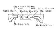
ファイバ連結部22には、第1の光ドロップケーブル101の2つの先端部分10a11,10a12および第2の光ドロップケーブル102の2つの先端部分10a21,10a22を第1および第2の支持部261,262に良好に導くためのケーブルガイド手段として、第1乃至第4のガイドピン281〜284が設けられている。
すなわち、第1の光ドロップケーブル101の先端部分10a11を第1の支持部261の方へ良好に導くための第1のガイドピン281と、第1の光ドロップケーブル101の先端部分10a12を第2の支持部262の方へ良好に導くための第2のガイドピン282と、第2の光ドロップケーブル102の先端部分10a21を第1の支持部261の方へ良好に導くための第3のガイドピン283と、第2の光ドロップケーブル102の先端部分10a22を第2の支持部262の方へ良好に導くための第4のガイドピン284とが、ファイバ連結部22に設けられている。The
That is, the first and the first guide pin 281 for better guiding the optical drop cable 101 of the front end portion 10a11 towards the first support portion 261, a first end of the optical drop cable 1012 second guide pin 28 for guiding the portion 10a12 well towards the second supporting portion 262, the second optical drop cable 102 of the front end portion 10a21 first supporting portion 261 the third guide pin 283, the fourth guide pin for better guiding the second optical drop cable 102 of the tip portion 10a22 towards the second supporting portion 262 for guiding better towards 284 and is provided in the
カバー30は、ハウジング20の平面形状とほぼ同一の平面形状を有している。カバー30とハウジング20とは互いの長手方向に沿った辺同士がヒンジ(不図示)によって開閉自在に連結されており、カバー30がハウジング20に対して閉じられた状態では、カバー30はハウジング20の上面を覆う。 The cover 30 has substantially the same planar shape as the planar shape of the
ハウジング20およびカバー30のヒンジで互いに連結された辺と対向する辺には、互いに係合し合う係合爪および係合凹部で構成される係合構造が設けられている。
すなわち、カバー30の長手方向両端部には第1および第2の係合爪30a1,30a2がそれぞれ設けられており、ハウジング20の長手方向両端部には、第1および第2の係合爪30a1,30a2がそれぞれ係合する第1および第2の係合凹部20b1,20b2がそれぞれ設けられている。また、ハウジング20の長手方向中央部には第3の係合爪20aが設けられており、カバー30の長手方向中央部には、第3の係合爪20aが係合する第3の係合凹部30bが設けられている。
このように、互いの係合関係が交互になるように第1乃至第3の係合爪30a1,30a2,20aおよび第1乃至第3の係合凹部20b1,20b2,30bの組を配置することで、閉じているカバー30を単純に開こうとしても両端部または中央部のいずれかで第1乃至第3の係合爪30a1,30a2,20aと第1乃至第3の係合凹部20b1,20b2,30bとが係合しているので、カバー30が不用意に開けられることを防止することができる。On the side opposite to the side connected to each other by the hinges of the
That is, first and second engagement claws 30a1 and 30a2 are provided at both ends in the longitudinal direction of the cover 30, respectively, and first and second engagement claws are provided at both ends in the longitudinal direction of the
In this manner, the first to
次に、本実施例による光ケーブル接続具1を用いて第1および第2の光ドロップケーブル101,102を接続する方法(光ケーブル接続方法)について説明する。
まず、第1の光ドロップケーブル101の第1の被覆131をその幅方向中央部で長手方向に沿って所定の長さだけ切り開いて第1の光ドロップケーブル101の先端部を2つの先端部分10a11,10a12に分岐させることにより、第1の光ファイバ心線111を露出させる。その後、第1の光ドロップケーブル101の2つの先端部分10a11,10a12の第1の被覆131を取り除くことにより、2本のテンションメンバ1211,1212を露出させる。
また、第2の光ドロップケーブル102の第2の被覆132(不図示)をその幅方向中央部で長手方向に沿って所定の長さだけ切り開いて第2の光ドロップケーブル102の先端部を2つの先端部分10a21,10a22に分岐させることにより、第2の光ファイバ心線112を露出させる。その後、第2の光ドロップケーブル102の2つの先端部分10a21,10a22の第2の被覆132を取り除くことにより、2本のテンションメンバ1221,1222を露出させる。Next, a method of connecting the first and second optical drop cables 101 and 102 using the optical cable connector 1 according to this embodiment (optical cable connection method) will be described.
First, a first predetermined a first coating 131 of the optical drop cable 101 along the longitudinal direction at the widthwise central portion first cut open for the length of the optical drop cable 101 tip the two The first optical fiber core wire 111 is exposed by branching to the tip portions 10a11 and 10a12 . Thereafter, the two tension members 1211 and 1212 are exposed by removing the first covering 131 of the two tip portions 10a11 and 10a12 of the first optical drop cable 101 .
The second second coating 132 (not shown) the second end of the optical drop cable 102 paving predetermined length along the longitudinal direction at the widthwise central portion of the optical drop cable 102 The second optical fiber core wire 112 is exposed by branching the portion into two tip portions 10a21 and 10a22 . Then, the two tension members 1221 and1222 are exposed by removing the second covering 132 of the two tip portions 10a21 and 10a22 of the second optical drop cable 102 .
続いて、第1および第2の光ドロップケーブル101,102を、露出した第1および第2の光ファイバ心線111,112が向き合うように対向させたのち、メカニカルスプライス25を用いて第1および第2の光ファイバ心線111,112の先端部同士を接続する(図1および図2参照)。これにより、第1および第2の光ドロップケーブル101,102が光学的に接続される。
なお、第1および第2の光ファイバ心線111,112の先端部同士を接続する際には、余長を確保してもよいが、余長を確保する必要は必ずしもない。Subsequently, after the first and second optical drop cable 101, 102, are opposed to the first and second optical fibers 11 exposed1, 112 face each other, using a
Incidentally, when connecting the first and second optical fibers 111, 112 of the distal ends may be secured extra length, but not necessarily need to secure extra length.
続いて、第1および第2の光ドロップケーブル101,102が接続された状態でメカニカルスプライス25をファイバ連結部22に保持させるとともに、第1および第2の光ドロップケーブル101,102を第1および第2のケーブル収容溝211,212にそれぞれ嵌め込む。ここで、ファイバ連結部22によるメカニカルスプライス25の保持は、メカニカルスプライス25を第1および第2の保持爪22a1,22a2の間に押し込むだけで簡単に行うことができる。Subsequently, the to retain the
続いて、第1の光ドロップケーブル101の先端部分10a11を第1のガイドピン281により第1の支持部261の方へ導いたのち、第1の光ドロップケーブル101の先端部分10a11から露出したテンションメンバ1211を第1の支持部261に載せて支持させるとともに、第2の光ドロップケーブル102の先端部分10a21を第3のガイドピン283により第1の支持部261の方へ導いたのち、第2の光ドロップケーブル102の先端部分10a21から露出したテンションメンバ1221を第1の支持部261に載せて支持させる。この状態で第1のねじ271を締め付けることによって、第1の支持部261と第1のねじ271の頭部との間で2本のテンションメンバ1211,1221を固定する。
なお、第1のねじ271を締め付ける際、2本のテンションメンバ1211,1221には、第1のねじ271の頭部により第1のねじ271の回転方向への力が作用する。そこで、この力が2本のテンションメンバ1211,1221への引張力として作用するように、2本のテンションメンバ1211,1221を第1の支持部261によって支持させるのが望ましい。具体的には、2本のテンションメンバ1211,1221が第1のねじ271の両側を第1のねじ271の締め付け方向に沿って互いに逆向きに通るように、2本のテンションメンバ1211,1221を配置する。これにより、第1および第2の光ドロップケーブル101,102の弛みを防止することができる。Subsequently, after the first optical drop cable 101 of the front end portion 10a11 by the first guide pin 281 led to the first direction of the supporting portion 261, the first tip portion of the optical drop cable 101 The tension member 1211 exposed from 10a11 is placed on and supported by thefirst support portion 261, and the tip portion 10a21 of thesecond
Incidentally, when tightening the first screw 271, the two tension members 1211, 1221, the force of the first screw 27first rotational direction acts by the first screw 271 of the head . Therefore, this force to act as a tensile force to the two tension members 1211, 1221, to the two tension members 1211, 1221 is supported by the first supporting portion 261 is desirable. Specifically, the two tension members 1211, 1221 to pass through the first sides of the screw 271 opposite to each other along the first screw 271 tightening direction, two tension members 1211 and 1221 are arranged. Thereby, the slack of the first and second optical drop cables 101 , 102 can be prevented.
続いて、第1の光ドロップケーブル101の先端部分10a12を第2のガイドピン282により第2の支持部262の方へ導いたのち、第1の光ドロップケーブル101の先端部分10a12から露出したテンションメンバ1212を第2の支持部262に載せて支持させるとともに、第2の光ドロップケーブル102の先端部分10a22を第4のガイドピン284により第2の支持部262の方へ導いたのち、第2の光ドロップケーブル102の先端部分10a22から露出したテンションメンバ1222を第2の支持部262に載せて支持させる。この状態で第2のねじ272を締め付けることによって、第2の支持部262と第2のねじ272の頭部との間で2本のテンションメンバ1212,1222を固定する。
なお、この場合にも、2本のテンションメンバ1212,1222が第2のねじ272の両側を第2のねじ272の締め付け方向に沿って互いに逆向きに通るように、2本のテンションメンバ1212,1222を配置することにより、第1および第2の光ドロップケーブル101,102の弛みを防止することができる。Subsequently, after the first optical drop cable 101 of the front end portion 10a12 led bytwo second guide pin 28 towards the second support portions 262, the first tip portion of the optical drop cable 101 The tension member 1212 exposed from 10a12 is placed on and supported by thesecond support portion 262, and the tip portion 10a22 of thesecond optical drop cable 102 is second supported by thefourth
Also in this case, two tension members 1212, 1222 to pass through the second opposite sides of the screw 272 to the second screw 27and second clamping opposite directions along the direction, the two by arranging the tension member12 12, 1222, it is possible to prevent the first and second slack of the optical drop cable 101, 102.
続いて、カバー30を閉じて、第1および第2の光ドロップケーブル101,102の第1および第2の光ファイバ心線111,112が露出した部分を覆う。カバー30を閉じる際に第1乃至第3の係合爪30a1,30a2,20aと第1乃至第3の係合凹部20b1,20b2,30bとをそれぞれ係合させることによって、ハウジング20に対してカバー30を固定する。これによって、カバー30が不用意に開くのを防止することができる。Subsequently, the cover 30 is closed to cover the exposed portions of the first and second optical fiber core wires 111 and 112 of the first andsecond optical drop cables 101 and 102 . When the cover 30 is closed, the first to
以上説明したように、光ケーブル接続具1を用いることによって、極めて簡単に、建物内で第1および第2の光ドロップケーブル101,102を接続することができる。
また、テンションメンバ1211,1212,1221,1222を第1および第2の支持部261,262と第1および第2のねじ271,272とを用いて固定することにより十分な引張強度を持たせることができるので、たとえば建物内で第1および第2の光ドロップケーブル101,102が何らかの原因で引っ張られても第1および第2の光ドロップケーブル101,102の接続を保つことができる。As described above, by using the optical cable connector 1, the first and second optical drop cables 101 and 102 can be connected very easily in the building.
Further, by fixing the tension members 1211 , 1212 , 1221 ,1222 using the first and second support portions 261 , 262 and the first and second screws 271 , 272. Since sufficient tensile strength can be provided, for example, even if the first and second optical drop cables 101 , 102 are pulled for some reason in the building, the first and second optical drop cables 101 , 102 connections can be maintained.
以上の説明では、第1の光ドロップケーブル固定手段として第1の支持部261および第1のねじ271を用いたが、図4に示すように、第1のねじ271の代わりに、互いに対向する2本のテンションメンバ1211,1221をそれぞれ固定する2つのねじ2711,2712を用いてもよい。この場合にも、ねじ2711,2712を締め付ける際のねじ2711,2712の回転によりテンションメンバ1211,1221に生じる力がテンションメンバ1211,1221の引張力として作用するように、テンションメンバ1211,1221を第1の支持部261によってそれぞれ支持させる。このように、テンションメンバ1211,1221ごとにねじ2711,2712を用いることにより、第1および第2の光ドロップケーブル101,102ごとに張力を調整して、より安定して第1および第2の光ドロップケーブル101,102を接続することができる。In the above description, the first support portion 261 and the first screw 271 are used as the first optical drop cable fixing means, but as shown in FIG. 4, instead of thefirst screw 271 , Two screws 2711 and 2712 for fixing the two tension members 1211 and 1221 facing each other may be used. In this case, as screw 2711, 2712 forces occurring tension member 1211, 1221 by the rotation of the time of tightening the screws 2711, 2712 acts as a tension of the tension member 1211, 1221 The tension members 1211 and 1221 are supported by thefirst support portion 261 , respectively. As described above, by using the screws 2711 and 2712 for each of the tension members 1211 and 1221 , the tension is adjusted for each of the first and second optical drop cables 101 and 102 , and more stably. The first and second optical drop cables 101 and 102 can be connected.
同様に、第2の光ドロップケーブル固定手段として第2の支持部262および第2のねじ272を用いたが、第2のねじ272の代わりに、互いに対向する2本のテンションメンバ1212,1222をそれぞれ固定する2つのねじ2721,2722(不図示)を用いてもよい。この場合にも、ねじ2721,2722を締め付ける際のねじ2721,2722の回転によりテンションメンバ1212,1222に生じる力がテンションメンバ1212,1222の引張力として作用するように、テンションメンバ1212,1222を第2の支持部262によってそれぞれ支持させる。Similarly, the second support portion 262 and the second screw 272 are used as the second optical drop cable fixing means. Instead of the second screw 272 , the two tension members 12 facing each other are used.12, 1222 are fixed respectively two screws 2721, 2722 (not shown) may be used. In this case, as forces occurring tension member12 12, 1222 by the rotation of the screw 2721, 2722 when tightening the screws 2721, 2722 acts as a tension of the tension member12 12, 1222 , it is respectively supported by the tension member12 12, 1222 the second supporting portion 262.
また、第1および第2の光ドロップケーブル固定手段としては、4本のテンションメンバ1211,1212,1221,1222を固定することができるものであれば、如何なる構造を採用することもできる。以下に、第1および第2の光ドロップケーブル固定手段のその他の例を幾つか示す。Further, as the first and second optical drop cable fixing means, as long as it can fix the four tension members 1211, 1212, 1221, 1222, also be adopted any structure it can. Several other examples of the first and second optical drop cable fixing means are shown below.
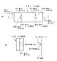
図5(a),(b)に示す例では、第1の光ドロップケーブル固定手段は、第1の支持部411と、2つのねじ4211,4212(ねじ4212は不図示)とを備える。
ここで、第1の支持部411には、同図(b)に示すように、第1の光ドロップケーブル101の先端部分10a11から露出されたテンションメンバ1211が挿入される挿通孔41a11と、第2の光ドロップケーブル102の先端部分10a21から露出されたテンションメンバ1221が挿入される挿通孔41a12(不図示)とが形成されている。また、第1の支持部411の外表面には、2つの挿通孔41a11,41a12にそれぞれ達する2つのねじ孔41b11,41b12(ねじ孔41b12は不図示)が開口されている。
2つの挿通孔41a11,41a12に2本のテンションメンバ1211,1221をそれぞれ通した状態で、2つのねじ孔41b11,41b12に2つのねじ4211,4212がそれぞれねじ込まれる。これにより、2本のテンションメンバ1211,1221は、2つの挿通孔41a11,41a12内で2つのねじ4211,4212によってそれぞれ締め付けられて固定される。2つのねじ4211,4212を緩めれば、2本のテンションメンバ1211,1221を2つの挿通孔41a11,41a12から引き出すことができる。In the example shown in FIGS. 5A and 5B, the first optical drop cable fixing means includes a first support portion 411 , two screws 4211 and 4212 (the screw 4212 is not shown), and Is provided.
Here, as shown in FIG. 5B, an insertion hole into which the tension member 1211 exposed from the distal end portion 10a11 of thefirst optical drop cable 101 is inserted into the first support portion 411 . and 41a11, an insertion hole 41a12 that tension member 1221 which is exposed from the second optical drop cable 102 of the front end portion 10a21 is inserted and (not shown) is formed. Further, two screw holes 41b11 and 41b12 (the screw holes 41b12 are not shown) reaching the two insertion holes 41a11 and 41a12 are opened on the outer surface of the first support portion 411 . .
Two screws 4211 and 4212 are respectively screwed into the two screw holes 41b11 and 41b12 in a state where the two tension members 1211 and 1221 are passed through the two insertion holes 41a11 and 41a12 , respectively. Thus, the two tension members 1211 and 1221 are fastened and fixed by the two screws 4211 and 4212 in the two insertion holes 41a11 and 41a12 respectively. If the two screws 4211 and 4212 are loosened, the two tension members 1211 and 1221 can be pulled out from the two insertion holes 41a11 and 41a12 .
同様に、第2の光ドロップケーブル固定手段は、第2の支持部412(不図示)と、2つのねじ4221,4222(不図示)とを備える。
第2の支持部412には、第1の光ドロップケーブル101の先端部分10a12から露出されたテンションメンバ1212が挿入される挿通孔41a21(不図示)と、第2の光ドロップケーブル102の先端部分10a22から露出されたテンションメンバ1222が挿入される挿通孔41a22(不図示)とが形成されている。また、第2の支持部412の外表面には、2つの挿通孔41a21,41a22にそれぞれ達する2つのねじ孔41b21,41b22(不図示)が開口されている。
2つの挿通孔41a21,41a22に2本のテンションメンバ1212,1222をそれぞれ通した状態で、2つのねじ孔41b21,41b22に2つのねじ4221,4222がそれぞれねじ込まれる。これにより、2本のテンションメンバ1212,1222は、2つの挿通孔41a21,41a22内で2つのねじ4221,4222によってそれぞれ締め付けられて固定される。2つのねじ4221,4222を緩めれば、2本のテンションメンバ1212,1222を2つの挿通孔41a21,41a22から引き出すことができる。Similarly, the second optical drop cable fixing means includes a second support portion 412 (not shown) and two screws 4221 and 4222 (not shown).
The second support portion 412 has an insertion hole 41a21 (not shown) into which the tension member 1212 exposed from the tip portion 10a12 of thefirst
Two insertion holes 41a21, 41a22 to two tension members12 12, 1222 in a state in which through respective two screw holes 41b21, 41b22 the two screws 4221, 4222 are screwed respectively. As a result, the two tension members 1212 and 1222 are fastened and fixed by the two screws 4221 and 4222 in the two insertion holes 41a21 and 41a22 , respectively. Loosening the two screws 4221, 4222, it can be drawn two tension members12 12, 1222 from two insertion holes 41a21, 41a22.
図6(a),(b)に示す例では、第1の光ドロップケーブル固定手段は、第1の支持部431と、2つの押さえ金具4411,4412(押さえ金具4412は不図示)と、2つのねじ4511,4512(ねじ4512は不図示)とを備える。
ここで、第1の支持部431の長手方向両端部には、2つのねじ4511,4512を第1の支持部431にそれぞれねじ込むための2つのねじ孔43a11,43a12(ねじ孔43a12は不図示)がそれぞれ形成されている。また、2つの押さえ金具4411,4412には、2つのねじ4511,4512をそれぞれ通すための孔44a11,44a12(孔44a12は不図示)がそれぞれ形成されている。
第1の支持部431によって支持された第1の光ドロップケーブル101の先端部分10a11から露出されたテンションメンバ1211および第2の光ドロップケーブル102の先端部分10a21から露出されたテンションメンバ1221の上に2つの押さえ金具4411,4412をそれぞれ被せたのち、2つのねじ4511,4512を2つの押さえ金具4411,4412の2つの孔44a11,44a12にそれぞれ通して第1の支持部431の2つのねじ孔43a11,43a12にそれぞれねじ込む。これにより、テンションメンバ1211は、第1の支持部431と押さえ金具4411とで挟まれて固定され、テンションメンバ1221は、第1の支持部431と押さえ金具4412とで挟まれて固定される。
このように、押さえ金具4411,4412を用いることにより、テンションメンバ1211,1221をより確実に固定することができるようになるとともに、第1の支持部431のテンションメンバ1211,1221を固定することができる領域を広げることができるので、テンションメンバ1211,1221の支持位置(載置位置)の自由度を向上させることができる。FIG 6 (a), in the example shown in (b), the first optical drop cable fixing means includes a first support portion 431, two retainer member 4411, 4412 (retainer member 4412 is not shown ) And two screws 4511 and 4512 (screw 4512 is not shown).
Here, the first longitudinal end portion of the supporting portion 431, two screws 4511, 4512 first 2 for screwing the respective support part 431 of the screw holes 43a11, 43a12 (screws hole 43a12 is not shown) are formed. In addition, holes 44a11 and 44a12 (holes 44a12 are not shown) for passing two screws 4511 and 4512 respectively are formed in the two presser fittings 4411 and 4412 , respectively.
The tension member 1211 exposed from the tip portion 10a11 of thefirst
In this way, by using the retainer member 4411, 4412, tension member 1211, 1221 with it is possible to more securely fix the first support portion 431 of the tension member 1211, Since the area where 1221 can be fixed can be expanded, the degree of freedom of the support positions (mounting positions) of the tension members 1211 and 1221 can be improved.
同様に、第2の光ドロップケーブル固定手段は、第2の支持部432と、2つの押さえ金具4421,4422(不図示)と、2つのねじ4521,4522(不図示)とを備える。
ここで、第2の支持部432の長手方向両端部には、2つのねじ4521,4522を第2の支持部432にそれぞれねじ込むための2つのねじ孔43a21,43a22(不図示)がそれぞれ形成されている。また、2つの押さえ金具4421,4422には、2つのねじ4521,4522をそれぞれ通すための孔44a21,44a22(不図示)がそれぞれ形成されている。
第2の支持部432によって支持された第1の光ドロップケーブル101の先端部分10a12から露出されたテンションメンバ1212および第2の光ドロップケーブル102の先端部分10a22から露出されたテンションメンバ1222の上に2つの押さえ金具4421,4422をそれぞれ被せたのち、2つのねじ4521,4522を2つの押さえ金具4421,4422の2つの孔44a21,44a22にそれぞれ通して第2の支持部432の2つのねじ孔43a21,43a22にそれぞれねじ込む。これにより、テンションメンバ1212は、第2の支持部432と押さえ金具4421とで挟まれて固定され、テンションメンバ1222は、第2の支持部432と押さえ金具4422とで挟まれて固定される。Similarly, the second optical drop cable fixing means includes a second support portion 432 , two presser fittings 4421 and 4422 (not shown), and two screws 4521 and 4522 (not shown). Is provided.
Here, the second longitudinal ends of the supporting portion 432, two screws 4521, 4522 a second 2 for screwing respectively to the supporting portion 432 of the screw holes 43a21, 43a22 (not Are respectively formed. In addition, the two retainer member 4421, 4422, two screws 4521, 4522 the hole 44a21 for the passage of each, 44a22 (not shown) are formed.
The tension member 1212 exposed from the tip portion 10a12 of thefirst optical drop cable 101 supported by the second support portion 432 and the tip portion 10a22 of thesecond optical drop cable 102 are exposed. After covering two retainer member 4421, 4422 respectively on the tension member 1222, the two screws 4521, 4522 two holes 44a21, 44a22 of the two retainer member 4421, 4422 They are respectively screwed into the two screw holes 43a21 and 43a22 of the second support part 432 . Thus, the tension members 1212 are fixed by being sandwiched between the second support portions 432 and the retainer member 4421, the tension member 1222 is sandwiched between the second support portions 432 and the retainer member 4422 Fixed.
図7に示す例では、第1の光ドロップケーブル固定手段は、第1の支持部261によって支持された第1の光ドロップケーブル101の先端部分10a11から露出されたテンションメンバ1211および第2の光ドロップケーブル102の先端部分10a21から露出されたテンションメンバ1221を複数のねじを用いて一緒に固定する点で、2本のテンションメンバ1211,1221を1つのねじを用いてそれぞれ固定する図1や図4に示した第1の光ドロップケーブル固定手段と異なる。
すなわち、第1の光ドロップケーブル固定手段は、第1の支持部261と、3本のねじ27a1,27b1,27c1とを備える。
3本のねじ27a1,27b1,27c1を第1の支持部261にねじ込むことにより、第1の支持部261によって支持された2本のテンションメンバ1211,1221を第1の支持部261と3本のねじ27a1,27b1,27c1の頭部との間で締め付ける。これにより、より十分な引張強度を持たせて第1および第2の光ドロップケーブル101,102をハウジング20に固定することができる。In the example shown in FIG. 7, the first optical drop cable fixing means includes the tension member 1211 exposed from the tip portion 10a11 of thefirst
That is, the first optical drop cable fixing means includes a first support portion 261 and three
By screwing the three
同様に、第2の光ドロップケーブル固定手段は、第2の支持部262(不図示)と、3本のねじ27a2,27b2,27c2(不図示)とを備える。
3本のねじ27a2,27b2,27c2を第2の支持部262にねじ込むことにより、第2の支持部262によって支持された2本のテンションメンバ1212,1222を第2の支持部262と3本のねじ27a2,27b2,27c2の頭部との間で締め付ける。これにより、より十分な引張強度を持たせて第1および第2の光ドロップケーブル101,102をハウジング20に固定することができる。Similarly, the second optical drop cable fixing means includes a second support portion 262 (not shown) and three
By screwing the three
なお、第1および第2の光ドロップケーブル固定手段を構成するねじの数を3つとしたが、2つでもよいし4つ以上であってもよい。 Although the number of screws constituting the first and second optical drop cable fixing means is three, it may be two or four or more.
以上、第1および第2の光ドロップケーブル固定手段について種々の例について説明したが、4本のテンションメンバ1211,1212,1221,1222に余長を持たせる場合には、その余長を吸収するために、ハウジング20の表面に対する第1および第2の光ファイバ心線111,112の接続位置と4本のテンションメンバ1211,1212,1221,1222の固定位置との間に高低差を設けることが好ましい。Above, when have been described various examples for the first and second optical drop cable fixing means, the four tension members 1211, 1212, 1221, 1222 to have a surplus length, the remaining to absorb long, first and second optical fibers 111, 112 of the connecting position and the present 4 tension member 1211 to the surface of the
以上の説明では、図2に示したように第1および第2の光ドロップケーブル101,102の先端部分10a11,10a12,10a21,10a22を第1および第2の支持部261,262の方へ良好に導くためのケーブルガイド手段として第1乃至第4のガイドピン281〜284を用いたが、第1乃至第4のガイドピン281〜284の代わりに、クランプ爪4711〜4714,4721〜4724(クランプ爪4713,4714,4721〜4724は不図示)用いてもよい。ここで、クランプ爪4711〜4714,4721〜4724は、ペンチのような簡易な工具で塑性変形させることができる金属板などで構成することができる。In the above description, the first and second optical drop cable 101, 102 of the front end portion10a 11, 10a 12, 10a 21 ,
すなわち、図8(a),(b)に示すように、第1の光ドロップケーブル101の先端部分10a11は、一対のクランプ爪4711,4712が開いた状態で一対のクランプ爪4711,4712の間にそれぞれ挿入される。この状態で一対のクランプ爪4711,4712を閉じ、第1の光ドロップケーブル101の先端部分10a11を一対のクランプ爪4711,4712で挟み込むことにより、第1の光ドロップケーブル101の先端部分10a11を第1の支持部261の方へ良好に導く。
同様にして第1の光ドロップケーブル101の先端部分10a12を一対のクランプ爪4713,4714で挟み込むことにより、第1の光ドロップケーブル101の先端部分10a12を第2の支持部262の方へ良好に導き、同様にして第2の光ドロップケーブル102の先端部分10a21を一対のクランプ爪4721,4722で挟み込むことにより、第2の光ドロップケーブル102の先端部分10a21を第1の支持部261の方へ良好に導き、同様にして第2の光ドロップケーブル102の先端部分10a22を一対のクランプ爪4723,4724で挟み込むことにより、第2の光ドロップケーブル102の先端部分10a22を第2の支持部262の方へ良好に導く。That is, FIG. 8 (a), the (b), the first tip portion 10a11 of the optical drop cable 101, a pair of clamp jaws 4711, 4712 a pair of in a state of open clamp jaws 4711 and 4712 are inserted. Closing a pair of clamp jaws 4711, 4712 in this state, by sandwiching a first optical drop cable 101 of the front end portion 10a11 in a pair of clamp jaws 4711, 4712, the first optical drop cable 10 favorably leads to thefirst tip portion 10a11 towards the first support portion 261.
First optical drop cable 101 of the front end portion 10a12 a pair of clamp jaws 4713 In the same manner, 47 by sandwiching at14, a first optical drop cable 101 of the front end portion 10a12 second supporting portion better guided towards 262, by sandwiching the second optical drop cable 102 of the tip portion 10a21 by a pair of clamp jaws 4721, 4722 in the same manner, the second optical drop cable 102 tip by sandwiching portions 10a21 at the first well guided toward the supporting portion 261, a second optical drop cable 102 of the front end portion 10a22 a pair of clamp jaws 4723 in the same manner, 4724, the The leading end portion 10a22 of the second optical drop cable 102 is satisfactorily guided toward the second support portion 262 .
なお、一対のクランプ爪4711,4712および一対のクランプ爪4713,4714は、第1の光ドロップケーブル101をハウジング20に固定する第1の光ドロップケーブル固定手段としても機能し、また、一対のクランプ爪4721,4722および一対のクランプ爪4723,4724は、第2の光ドロップケーブル102をハウジング20に固定する第2の光ドロップケーブル固定手段としても機能する。The pair of clamp jaws 4711, 4712, and a pair of clamp jaws 4713, 4714, also serve the first optical drop cable 101 as the first optical drop cable fixing means for fixing the
第1および第2の光ドロップケーブル101,102のハウジング20への固定は、4本のテンションメンバ1211,1212,1221,1222だけでなく、図1に示したケーブル保持部21a11,21a12,21a21,21a22のように、第1および第2の光ドロップケーブル101,102の先端部分10a11,10a12,10a21,10a22以外でも行うことは、第1および第2の光ドロップケーブル101,102をより安定してハウジング20に固定するのに好ましい。図9および図10に、第1および第2の光ドロップケーブル101,102の先端部分10a11,10a12,10a21,10a22以外で第1および第2の光ドロップケーブル101,102をハウジング20に固定するためのその他の例を示す。The first and second optical drop cables 101 , 102 are fixed to the
図9に示す例では、ハウジング20の上面に、第1および第2のケーブル押さえ231,232(第2のケーブル押さえ232は不図示)が、第1および第2のケーブル収容溝211,212をそれらの幅方向に横断するようにそれぞれ取り付けられている。
第1のケーブル押さえ231は、一方の端部が第1の軸部材23a1によってハウジング20に回動自在に支持されており、他方の端部が第1のねじ241によってハウジング20に固定される。第2のケーブル押さえ232も、同様に、一方の端部が第2の軸部材23a2(不図示)によってハウジング20に回動自在に支持されており、他方の端部が第2のねじ242(不図示)によってハウジング20に固定される。In the example shown in FIG. 9, first and second cable holders 231 and 232 (second cable holder 232 not shown) are formed on the upper surface of the
The first cable presser 231 has one end rotatably supported by the
第1および第2のケーブル押さえ231,232は、第1および第2のケーブル収容溝211,212にそれぞれ挿入された第1および第2の光ドロップケーブル101,102を第1および第2のケーブル収容溝211,212内でそれぞれ固定する働きをする。そのために、第1および第2のケーブル押さえ231,232と第1および第2のケーブル収容溝211,212とは、第1および第2の光ドロップケーブル101,102を第1および第2のケーブル収容溝211,212内にそれぞれ挿入した状態で第1および第2のねじ241,242によってハウジング20にそれぞれ固定した際に、第1および第2のケーブル押さえ231,232が第1および第2の光ドロップケーブル101,102を第1および第2のケーブル収容溝211,212に向けてそれぞれ押圧するように構成されている。The first and second cable holders 231 and 232 are used to connect the first and second optical drop cables 101 and 102 respectively inserted into the first and second cable housing grooves 211 and 212 . The first and second cable receiving grooves 211 and 212 function to be fixed respectively. For this purpose, the first and second cable holders 231 and 232 and the first and second cable housing grooves 211 and 212 connect the first and second optical drop cables 101 and 102 to the first. When the first and second cable receiving grooves 211 and 212 are inserted into the
第1および第2のケーブル押さえ231,232と第1および第2のケーブル収容溝211,212とをこのように構成する例としては、以下に示すような構成が挙げられる。
(1)第1および第2のケーブル収容溝211,212の深さを第1および第2の光ドロップケーブル101,102の厚みよりも浅くして、第1および第2のケーブル収容溝211,212から出っ張った部分を第1および第2のケーブル押さえ231,232でそれぞれ押圧する構成。
(2)第1および第2のケーブル押さえ231,232がハウジング20に固定された状態において、第1および第2のケーブル押さえ231,232の第1および第2のケーブル収容溝211,212と対向する領域に第1および第2の凸部(不図示)をそれぞれ設け、第1および第2の凸部によって第1および第2の光ドロップケーブル101,102をそれぞれ押圧する構成。An example of the configuration of the first and second cable holders 231 and 232 and the first and second cable housing grooves 211 and 212 in this manner is as follows.
(1) The first and second cable receiving grooves 211 , 212 are made shallower than the first and second optical drop cables 101 , 102. The structure which presses the part protruded from the accommodation grooves 211 and 212 with the first and second cable holders 231 and 232 , respectively.
(2) In the state where the first and second cable holders 231 and 232 are fixed to the
図10に示す例では、第1および第2の凸部321,322(第2の凸部322は不図示)をカバー30の長手方向両端部にカバー30と一体的にそれぞれ設けることによって、第1および第2の光ドロップケーブル101,102をハウジング20に固定する。ここで、第1および第2の凸部321,322は、カバー30を閉じた状態で第1および第2のケーブル収容溝211,212と対向する領域にそれぞれ設けられている。In the example shown in FIG. 10, first and second convex portions 321 and 322 (the second convex portion 322 is not shown) are provided integrally with the cover 30 at both ends in the longitudinal direction of the cover 30. Thus, the first and second optical drop cables 101 and 102 are fixed to the
第1の凸部321を用いて第1の光ドロップケーブル101を固定するには、第1の光ドロップケーブル101を第1のケーブル収容溝211内に嵌め込んだのち、カバー30を閉じる。カバー30を閉じることによって、第1の光ドロップケーブル101はカバー30に設けられた第1の凸部321によって押圧され、ハウジング20に固定される。第2の光ドロップケーブル102も、同様にして、第2の凸部322を用いてハウジング20に固定される。In order to fix thefirst optical drop cable 101 using the first convex portion 321 , the first optical drop cable 101 is fitted into the first cable housing groove 211 , and then the cover 30. Close. By closing the cover 30, the first optical drop cable 101 is pressed by thefirst convex portion 321 provided on the cover 30 and fixed to the
このように、第1および第2の光ドロップケーブル101,102をハウジング20に固定するための第1および第2の凸部321,322をカバー30に設けることにより、光ケーブル接続具の構造を簡単化することができる。Thus, by providing the cover 30 with the first and second convex portions 321 and 322 for fixing the first and second optical drop cables 101 and 102 to the
次に、光ケーブル接続具1の建物内での設置方法について説明する。
光ケーブル接続具1は、そのまま建物内に設置してもよいが、壁面あるいは床面に固定することが好ましい。Next, the installation method in the building of the optical cable connector 1 is demonstrated.
The optical cable connector 1 may be installed in a building as it is, but is preferably fixed to a wall surface or a floor surface.
図11(a),(b)に、光ケーブル接続具1を建物の室内壁面に取り付けられるようにした例を示す。この例では、同図(a)に示すように、光ケーブル接続具1の背面に第1および第2の取付け穴501,502を形成し、同図(b)に示すように、第1および第2の取付け穴501,502に、室内の壁面55に設けられた第1および第2のフック511,512(第2のフック512は不図示)がそれぞれ挿入される構成となっている。FIGS. 11A and 11B show an example in which the optical cable connector 1 is attached to the indoor wall surface of a building. In this example, as shown in FIG. 5A, first and second mounting holes 501 and 502 are formed on the back surface of the optical cable connector 1, and as shown in FIG. The first and second hooks 511 and 512 (the second hook 512 is not shown) provided on the indoor wall surface 55 are inserted into the second mounting holes 501 and 502 , respectively. It has become.
ここで、第1のフック511は、図11(b)に示すように、壁面55に突設された第1の軸部51a1と、第1の軸部51a1の先端の、第1の軸部51a1よりも直径の大きい第1の頭部51b1とを有する。また、第1の取付け穴501は、図11(a)に示すように、第1のフック511の第1の頭部51b1が挿入できるサイズを有する第1のフック挿入部50a1と、第1のフック挿入部50a1に挿入された第1のフック511の第1の頭部51b1を引っ掛けるための、第1のフック挿入部50a1から図示上向きに延びて形成された第1の引掛け部50b1とを有する。
第2のフック512は、第1のフック511と同様に、壁面55に突設された第2の軸部51a2(不図示)と、第2の軸部51a2の先端の、第2の軸部51a2よりも直径の大きい第2の頭部51b2(不図示)とを有する。また、第2の取付け穴502は、第1の取付け穴501と同様に、第2のフック512の第2の頭部51b2が挿入できるサイズを有する第2のフック挿入部50a2と、第2のフック挿入部50a2に挿入された第2のフック512の第2の頭部51b2を引っ掛けるための、第2のフック挿入部50a2から上向きに延びて形成された第2の引掛け部50b2とを有する。Here, the first hook 511, as shown in FIG. 11 (b), a first shaft portion 51a1 projecting from the wall 55, the first shaft portion 51a1 of the tip, first And a first head portion 51b1 having a diameter larger than that of the shaft portion 51a1 . Further, as shown in FIG. 11A, the first mounting hole 501 is formed with a first
Similarly to the first hook 511 , thesecond hook 512 includes a second shaft portion 51a2 (not shown) projecting from the wall surface 55, and a second shaft portion 51a2 at the tip of thesecond shaft portion 51a2 . And a second head portion 51b2 (not shown) having a diameter larger than that of thetwo shaft portions 51a2 . The second mounting holes 502, like the first mounting hole 501, the second
これにより、第1の取付け穴501の第1のフック挿入部50a1に第1のフック511を挿入するとともに第2の取付け穴502の第2のフック挿入部50a2に第2のフック512を挿入し、その状態で光ケーブル接続具1を壁面55に対して図示下向きに移動させると、光ケーブル接続具1は第1および第2のフック511,512に係合するので、光ケーブル接続具1を壁面55に固定することができる。Thus, the first mounting hole 501 of the first
なお、第1および第2の取付け穴501,502と第1および第2のフック511,512の形態は、互いに係合し得る形態であれば、図11(a),(b)に示した形態に限られるものではない。
また、光ケーブル接続具1を壁面55に固定する手段としては、上述したような係合を利用したものに限らず、その他にも、ねじや両面テープを利用したものなど、任意の手段を用いることができる。Note that the first and second mounting holes 501 , 502 and the first and second hooks 511 , 512 can be configured as shown in FIGS. It is not limited to the form shown in ().
In addition, the means for fixing the optical cable connector 1 to the wall surface 55 is not limited to the one using the above-described engagement, and any other means such as one using a screw or a double-sided tape may be used. Can do.
次に、光ケーブル接続具1の保護方法について説明する。
光ケーブル接続具1は、保護スリーブで保護してもよい。Next, a method for protecting the optical cable connector 1 will be described.
The optical cable connector 1 may be protected by a protective sleeve.
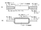
図12(a),(b)に示す例では、保護スリーブ60は、ゴム製の第1および第2のチューブ611,612を有する。ここで、第1および第2のチューブ611,612は、一端が光ケーブル接続具1のハウジング20の近傍でハウジング20から延出した第1および第2の光ドロップケーブル101,102にそれぞれ取り付けられている。
なお、図12(a),(b)では、第1および第2のチューブ611,612は断面で示されている。In the example shown in FIGS. 12A and 12B, the protective sleeve 60 includes first and second tubes 611 and 612 made of rubber. Here, the first and second tubes 611 , 612 are connected to the first and second optical drop cables 101 , 102 withone ends extending from the
In FIGS. 12A and 12B, the first and second tubes 611 and 612 are shown in cross section.
第1および第2の光ドロップケーブル101,102の接続作業時には、図12(a)に示すように、第1および第2のチューブ611,612の開放した他端側は、固定された一端よりもハウジング20から離れた側を向いている。第1および第2の光ドロップケーブル101,102の接続が完了したのちは、図12(b)に示すように、第1および第2のチューブ611,612を、開放した他端側が光ケーブル接続具1のハウジング20を通過するように反転させる。これにより、光ケーブル接続具1のハウジング20は第1および第2のチューブ611,612によって全体が覆われる。At the time of connecting the first and second optical drop cables 101 and 102 , as shown in FIG. 12A, the opened other end side of the first and second tubes 611 and 612 is fixed. It faces the side away from the
なお、第1および第2のチューブ611,612を用いた例を示したが、チューブの長さが光ケーブル接続具1をカバーするのに十分な長さを有している場合は、1つのチューブのみとしてもよい。
また、光ケーブル接続具1が接触することによる第1および第2のチューブ611,612の損傷を防止するために、光ケーブル接続具1の第1および第2のチューブ611,612と接触する箇所についてはR加工(丸み付け加工)を施すことが好ましい。In addition, although the example using the 1st and 2nd tube 611 and 612 was shown, when the length of the tube has a sufficient length to cover the optical cable connector 1, Only one tube may be used.
Further, in order to prevent the first and second tubes 611, 612 of the damage to the optical cable connector 1 is in contact, the first and second tubes 61 of the optical cable connector 11, 612 and the contact It is preferable to apply R processing (rounding processing) to the place to be performed.
図13(a),(b)に示す例では、保護スリーブ70は、光ケーブル接続具1を包囲するように、第1および第2のカップ状部材711,712を向かい合わせた構成を有する円筒状のスリーブである。In the example shown in FIGS. 13A and 13B, the protective sleeve 70 has a configuration in which the first and second cup-shaped members 711 and 712 face each other so as to surround the optical cable connector 1. It is a cylindrical sleeve.
第1および第2のカップ状部材711,712は、第1および第2の光ドロップケーブル101,102がそれぞれ挿通される第1および第2のケーブル挿通孔721,722が底部側端部に形成されるとともに、第1および第2のねじ溝731,732が開放側端部の内周面に形成されている。
光ケーブル接続具1の外面には、その長手方向中央部において、第1および第2のカップ状部材711,712の開放側端部を支持するリング状部74が形成されている。ここで、リング状部74の外周面には、第1および第2のカップ状部材711,712の第1および第2のねじ溝731,732に対応するねじ山が形成されている。The first and second cup-shaped members 711 and 712 have first and second cable insertion holes 721 and 722 through which the first and second optical drop cables 101 and 102 are inserted, respectively. The first and second screw grooves 731 , 732 are formed on the inner peripheral surface of the open end, while being formed at the bottom end.
On the outer surface of the optical cable connector1 , a ring-shaped
第1および第2の光ドロップケーブル101,102の接続作業は、第1および第2のカップ状部材711,712を開いた状態で行う。接続作業が完了すると、第1および第2のカップ状部材711,712を互いに接近させ、光ケーブル接続具1のリング状部74に螺合する。これによって、光ケーブル接続具1のハウジング20は第1および第2のカップ状部材711,712によって全体が覆われる。The connecting operation of the first and second optical drop cables 101 and 102 is performed with the first and second cup-shaped members 711 and 712 opened. When the connection work is completed, the first and second cup-shaped members 711 and 712 are brought close to each other and screwed into the ring-shaped
なお、図12(a),(b)および図13(a),(b)に示したように、光ケーブル接続具1を保護スリーブ60,70で保護する場合は、図1に示したカバー30は必ずしも設けなくともよい。 12A and 12B and FIGS. 13A and 13B, when the optical cable connector 1 is protected by the protective sleeves 60 and 70, the cover 30 shown in FIG. Is not necessarily provided.
また、上述した各実施例では、光ケーブル接続具1(ハウジング20)は全体として略直方体形状のものとして説明したが、その形状は特に限定されるものではなく、設置場所やデザイン上の要求などに応じた任意の形状であってよい。特に、図13(a),(b)に示したような円筒状の保護スリーブ70を備える場合は、その内部に収容される構造も全体として円筒状であることが望ましい。 Further, in each of the above-described embodiments, the optical cable connector 1 (housing 20) has been described as having a substantially rectangular parallelepiped shape as a whole, but the shape is not particularly limited, and the installation location, design requirements, etc. It may be of any shape depending on it. In particular, when a cylindrical protective sleeve 70 as shown in FIGS. 13A and 13B is provided, it is desirable that the structure accommodated therein is also cylindrical as a whole.
さらに、図1に示したように第1乃至第3の係合爪30a1,30a2,20aおよび第1乃至第3の係合凹部20b1,20b2,30bの組を配置することによりカバー30が不用意に開けられることを防止したが、図14(a)の右側に示すようなハウジング固定具80を用いてもよい。Further, as shown in FIG. 1, the first to
ハウジング固定具80は、カバー30およびハウジング20を弾性的に挟み込む第1および第2の挟持面811,812と、第1および第2の挟持面811,812の間の背面82とを備える。
第1および第2の挟持面811,812には、カバー30の上面の中央部およびハウジング20の底面の中央部にそれぞれ形成された第1および第2の溝851,852(第2の溝852は不図示)とそれぞれ嵌合する第1および第2の凹部831,832がそれぞれ形成されている。
また、第1および第2の挟持面811,812の先端には第1および第2の爪が設けられており、カバー30およびハウジング20を挟み込んだときに第1および第2の爪でカバー30およびハウジング20を掴むようにされている。The housing fixture 80 includes first and second clamping surfaces 811 and 812 that elastically sandwich the cover 30 and the
The first and second clamping surfaces 811 , 812 are provided with first and second grooves 851 , 852 (the first and second grooves 851 , 852 formed in the center of the upper surface of the cover 30 and the center of the bottom of the
Further, first and second claws are provided at the tips of the first and second clamping surfaces 811 and 812 , and the first and second claws are used when the cover 30 and the
図14(b)に示すように、カバー30が閉じられた光ケーブル接続具1を第1および第2の凹部831,832が第1および第2の溝851,852に嵌合するまでハウジング固定具80に挿入し、第1および第2の挟持面811,812が内側に閉じようとする力を利用してカバー30およびハウジング20をハウジング固定具80で挟み込むことにより、カバー30が不用意に開けられることを防止することができる。As shown in FIG. 14B, the first and second recesses 831 and 832 fit the first and second grooves 851 and 852 in the optical cable connector 1 with the cover 30 closed. The cover 30 and the
以上説明したように、本発明の光ケーブル接続具は、たとえば、建物外から建物内に引き込まれた光ドロップケーブルと建物内に敷設された光ドロップケーブルとを建物内で接続するのに利用することができる。 As described above, the optical cable connector of the present invention is used to connect, for example, an optical drop cable drawn into the building from outside the building and an optical drop cable laid in the building within the building. Can do.
1 光ケーブル接続具
101,102 第1および第2の光ドロップケーブル
10a11,10a12,10a21,10a22 先端部分
111,112 第1および第2の光ファイバ心線
1211,1212,1221,1222 テンションメンバ
131 第1の被覆
20 ハウジング
20a,30a1,30a2 第1乃至第3の係合爪
20b1,20b2,30b 第1乃至第3の係合凹部
211,212 第1および第2のケーブル収容溝
21a11,21a12,21a21,21a22 ケーブル保持部
22 ファイバ連結部
22a1,22a2 第1および第2の保持爪
231 第1のケーブル押さえ
23a1 第1の軸部材
241 第1のねじ
25 メカニカルスプライス
261,262 第1および第2の支持部
271,272 第1および第2のねじ
2711,2712 ねじ
27a1,27b1,27c1 ねじ
281〜284 第1乃至第4のガイドピン
30 カバー
30a1,30a2 第1および第2の係合爪
30b 第3の係合凹部
321 第1の凸部
411 第1の支持部
41a11 挿通孔
41b11 ねじ孔
4211 ねじ
431 第1の支持部
43a11 ねじ孔
4411 押さえ金具
44a11 孔
4511 ねじ
4711,4712 クランプ爪
501,502 第1および第2の取付け穴
50a1,50a2 第1および第2のフック挿入部
50b1,50b2 第1および第2の引掛け部
511 第1のフック
51a1 第1の軸部
51b1 第1の頭部
55 壁面
60 保護スリーブ
611,612 第1および第2のチューブ
70 保護スリーブ
711,712 第1および第2のカップ状部材
721,722 第1および第2のケーブル挿通孔
731,732 第1および第2のねじ溝
74 リング状部
80 ハウジング固定具
811,812 第1および第2の挟持面
82 背面
831,832 第1および第2の凹部
851 第1の溝1 optical cable connector 101 , 102 first and second optical drop cables 10a11 , 10a12 , 10a21 , 10a22 tip portions 111 , 112 first and second optical fiber core wires 1211 , 1212 , 1221 , 1222 tension member 131 first covering 20 housings 20 a, 30 a1 , 30 a2 first to third engaging claws 20 b1 , 20 b2 , 30 b first to third engaging recesses 211 , 212 First and second cable receiving grooves 21a11 , 21a12 , 21a21 , 21a22 Cable holding part 22 Fiber connecting parts 22a1 , 22a2 First and second holding claws 231 First cable presser 23a1 first shaft member 241 a first screw 25 mechanical splice 261, 262 first and second support portions 271, 272 first and second screw 2711 2712 screw 27a1 27b1, 27c1 screw 281-284 first to fourth guide pin 30 cover 30a1, 30a2 the first and second engagement claw 30b third engagement recess 321 first convex portion 411 1st support part 41a11 insertion hole 41b11 screw hole 4211 screw 431 1st support part 43a11 screw hole 4411 holding metal fitting 44a11 hole 4511 screw 4711 , 4712 clamp claws 501 , 502 First and second mounting holes 50a1 and 50a2 First and second hook insertion portions 50b1 and 50b2 First and second hook portions 511 First hook 51a1 First shaft portion 51b1 First head portion 55 Wall surface 60 Protective sleeves 611 , 612 First and second tubes 70 Protective sleeves 711 , 712 First and second cup-shaped members 721 , 722 First and second I of the cable insertion holes 731, 732 first and second It grooves 74 ring-shaped portion 80 housing the fixture 811, 812 first and rear 831 second clamping face 82, 832 first and second recesses 851 first groove
Claims (16)
Translated fromJapanese前記第1および第2の光ドロップケーブルを接続した状態で固定するためのハウジング(20)と、
第1および第2の光ドロップケーブル固定手段とを具備し、
前記ハウジングの上面に、前記第1および第2の光ドロップケーブルをそれぞれ収容するための第1および第2のケーブル収容溝(211,212)が、該ハウジングの両端部から該ハウジングの中央部に向かって延びてそれぞれ形成されており、
前記第1および第2のケーブル収容溝の間の領域に、前記第1の光ドロップケーブルの第1の被覆(131)を該第1の光ドロップケーブルの幅方向中央部で長手方向に沿って所定の長さだけ切り開いて該第1の光ドロップケーブルの先端部を2つの先端部分(10a11,10a12)に分岐させることによって露出された第1の光ファイバ心線(111)と、前記第2の光ドロップケーブルの第2の被覆(132)を該第2の光ドロップケーブルの幅方向中央部で長手方向に沿って所定の長さだけ切り開いて該第2の光ドロップケーブルの先端部を2つの先端部分(10a21,10a22)に分岐させることによって露出された第2の光ファイバ心線(112)とを接続するためのファイバ連結部(22)が前記ハウジングの上面の凹部として形成されており、
前記ファイバ連結部に、前記第1および第2の光ファイバ心線を接続する光ファイバ心線接続手段を該光ファイバ心線接続手段の幅方向両側から保持する第1および第2の保持爪(22a1,22a2)が設けられており、
前記第1の光ドロップケーブル固定手段が、前記ファイバ連結部の前記光ファイバ心線接続手段の幅方向両側の一方側に設けられているとともに、前記第1の光ドロップケーブルのテンションメンバ(1211,1212)および第1の被覆(131)を含む前記2つの先端部分(10a11,10a12)のうちの一方(10a11)の第1の被覆(131)を取り除くことにより露出されたテンションメンバ(1211)と前記第2の光ドロップケーブルのテンションメンバ(1221,1222)および第2の被覆(132)を含む前記2つの先端部分(10a21,10a22)のうちの一方(10a21)の第2の被覆(132)を取り除くことにより露出されたテンションメンバ(1221)とを固定することにより前記第1および第2の光ドロップケーブルを前記ハウジングに固定する第1のテンションメンバ固定手段を有し、
前記第2の光ドロップケーブル固定手段が、前記ファイバ連結部の前記光ファイバ心線接続手段の幅方向両側の他方側に設けられているとともに、前記第1の光ドロップケーブルのテンションメンバ(1211,1212)および第1の被覆(131)を含む前記2つの先端部分(10a11,10a12)のうちの他方(10a12)の第1の被覆(131)を取り除くことにより露出されたテンションメンバ(1212)と前記第2の光ドロップケーブルのテンションメンバ(1221,1222)および第2の被覆(132)を含む前記2つの先端部分(10a21,10a22)のうちの他方(10a22)の第2の被覆(132)を取り除くことにより露出されたテンションメンバ(1222)とを固定することにより前記第1および第2の光ドロップケーブルを前記ハウジングに固定する第2のテンションメンバ固定手段を有し、
前記第1の光ドロップケーブルのテンションメンバおよび第1の被覆を含む前記2つの先端部分(10a11,10a12)と前記第2の光ドロップケーブルのテンションメンバおよび第2の被覆を含む前記2つの先端部分(10a21,10a22)とが、前記ファイバ連結部内において前記第1および第2のテンションメンバ固定手段に導かれている、
ことを特徴とする、光ケーブル接続具。An optical cable connector for connecting a first optical drop cable (101 ) drawn into the building from outside the building and a second optical drop cable (102 ) laid in the building inside the building. And
A housing (20) for securing the first and second optical drop cables in a connected state;
First and second optical drop cable fixing means,
First and second cable housing grooves (211 , 212 ) for housing the first and second optical drop cables, respectively, are formed on the upper surface of the housing from both ends of the housing to the center of the housing. Each extending towards the part,
In the region between the first and second cable receiving grooves, the first coating (131 ) of the first optical drop cable extends along the longitudinal direction at the center in the width direction of the first optical drop cable. A first optical fiber core (111 ) exposed by opening the first optical drop cable into a two end portions (10a11 , 10a12 ) by opening the first optical drop cable by a predetermined length. The second cover (132 ) of the second optical drop cable is cut by a predetermined length along the longitudinal direction at the center in the width direction of the second optical drop cable, and the second optical drop cable is cut. of the distal end portion of the two tips portion (10a21, 10a22) a second optical fiber which is exposed by the branch (112) and the fiber connecting portion for connecting the (22) of said housing As a recess on the top surface Formed,
First and second holding claws for holding optical fiber core connecting means for connecting the first and second optical fiber cores to the fiber connecting portion from both sides in the width direction of the optical fiber core connecting means ( 22a1 , 22a2 )
The first optical drop cable fixing means is provided on one side of both sides in the width direction of the optical fiber core connecting means of the fiber connecting portion, and thetension member (1211 of the first optical drop cable)., 1212) and the first coating (131), and is exposed by removing thefirst coating (131 ) of one of the two tip portions (10a11 , 10a12 ) (10a11 ). Of the two tip portions (10a21 , 10a22 )including the tension member (1211 ), thetension member (1221, 1222) of the second optical drop cableand the second covering (132) one (10a21) a second coating (132) the first and second optical mud by fixingthe exposed tension members (1221) by removing the of Having a first tension member fixing means for fixing up the cable to the housing,
The second optical drop cable fixing means is provided on the other side of both sides in the width direction of the optical fiber core connection means of the fiber connecting portion, and thetension member (1211 of the first optical drop cable)., 1212) and the first coating (131), the other of the two tip portions (10a11 , 10a12 ) is exposed by removing thefirst coating (131 ) of the other (10a12 ). Among the two tip portions (10a21 , 10a22 )including the tension member (1212 ), thetension member (1221, 1222) of the second optical drop cableand the second covering (132) It said first and second optical de by fixing the othera second cover (132) tension members (1222) which is exposed by removing the (10a22) The Ppukeburuhave a second tension members fixing means for fixing to thehousing,
The two tip portions (10a11, 10a12)including the tension member and the first covering of the firstoptical drop cable, and the two members including the tension member and the second covering of the second optical drop cable. Tip portions (10a21, 10a22) are led to the first and second tension member fixing means in the fiber connecting portion,
An optical cable connector characterized by that.
前記第2の光ドロップケーブル固定手段の前記第2のテンションメンバ固定手段が、前記第1の光ドロップケーブルの2つの先端部分(10a11,10a12)のうちの他方(10a12)から露出されたテンションメンバ(1212)および前記第2の光ドロップケーブルの2つの先端部分(10a21,10a22)のうちの他方(10a22)から露出されたテンションメンバ(1222)を支持するための第2の支持部(262)と、該第2の支持部によって支持された前記2本のテンションメンバ(1212,1222)を該第2の支持部と頭部との間で締め付けるための第2のねじ(272)とを有する、
ことを特徴とする、請求項1記載の光ケーブル接続具。The firsttension member fixing means of the first optical drop cablefixing means is exposed from one (10a11 ) of two tip portions (10a11 , 10a12 ) of the first optical drop cable. The tension member (1211 ) and the tension member (1221 ) exposed from one of the two tip portions (10a21 , 10a22 ) (10a21 ) of the second optical drop cable To fasten the first support portion (261 ) and the two tension members (1211 , 1221 ) supported by the first support portion between the first support portion and the head A first screw (271 ),
The second tension member fixing means of the second optical drop cable fixing means is exposed from the other (10a12 ) of the two tip portions (10a11 , 10a12 ) of the first optical drop cable. The tension member (1212 ) and the tension member (1222 ) exposed from the other (10a22 ) of the two tip portions (10a21 , 10a22 ) of the second optical drop cable To tighten the second support portion (262 ) and the two tension members (1212 , 1222 ) supported by the second support portion between the second support portion and the head A second screw (272 )
The optical cable connector according to claim 1, wherein:
前記第2の光ドロップケーブル固定手段の前記第2のテンションメンバ固定手段が、前記第2のねじの代わりに、前記第2の支持部によって支持された前記2本のテンションメンバ(1212,1222)をそれぞれ固定する2つのねじ(2721,2722)を有する、
ことを特徴とする、請求項2記載の光ケーブル接続具。The firsttension member fixing means of the first optical drop cable fixing meansis replaced with the two tension members (1211 , 12) supported by the first support portion instead of the first screw.21 ) having two screws (2711 , 2712 ) for fixing each,
The secondtension member fixing means of the second optical drop cable fixing meansis replaced with the two tension members (1212 , 12) supported by the second support portion instead of the second screw.22 ) having two screws (2721 , 2722 ) for fixing each
The optical cable connector according toclaim 2, wherein:
前記第1の光ドロップケーブルの2つの先端部分(10a11,10a12)のうちの一方(10a11)から露出されたテンションメンバ(1211)および前記第2の光ドロップケーブの2つの先端部分(10a21,10a22)のうちの一方(10a21)から露出されたテンションメンバ(1221)がそれぞれ挿入される2つの挿通孔(41a11,41a12)が形成された、かつ、外表面に該2つの挿通孔(41a11,41a12)にそれぞれ達する2つのねじ孔(41b11,41b12)が開口された第1の支持部(411)と、
前記2つのねじ孔(41b11,41b12)にそれぞれねじ込まれる2つのねじ(4211,4212)とを有し、
前記第2の光ドロップケーブル固定手段の前記第2のテンションメンバ固定手段が、
前記第1の光ドロップケーブルの前記2つの先端部分(10a11,10a12)のうちの他方(10a12)から露出されたテンションメンバ(1212)および前記第2の光ドロップケーブの前記2つの先端部分(10a21,10a22)のうちの他方(10a22)から露出されたテンションメンバ(1222)がそれぞれ挿入される2つの挿通孔(41a21,41a22)が形成された、かつ、外表面に該2つの挿通孔(41a21,41a22)にそれぞれ達する2つのねじ孔(41b21,41b22)が開口された第2の支持部(412)と、
前記2つのねじ孔(41b21,41b22)にそれぞれねじ込まれる2つのねじ(4221,4222)とを有する、
ことを特徴とする、請求項1記載の光ケーブル接続具。The firsttension member fixing means of the first optical drop cable fixing means;
The tension member (1211 ) exposed from one (10a11 ) of the two tip portions (10a11 , 10a12 ) of the first optical drop cable and the two tip portions of the second optical drop cable Two insertion holes (41a11 , 41a12 ) into which the tension members (1221 ) exposed from one (10a21 ) of (10a21 , 10a22 ) are respectively inserted are formed, and the outer surface a first support portion that the two insertion holes (41a11, 41a12) to reach each of the two screw holes (41b11, 41b12) is opened (411), the
Two screws (4211 , 4212 ) respectively screwed into the two screw holes (41b11 , 41b12 ),
The secondtension member fixing means of the second optical drop cable fixing means;
The tension member (1212 ) exposed from the other (10a12 ) of the two tip portions (10a11 , 10a12 ) of the first optical drop cable and the two of the second optical drop cable Two insertion holes (41a21 , 41a22 ) into which the tension members (1222 ) exposed from the other (10a22 ) of the tip portions (10a21 , 10a22 ) are respectively inserted are formed, and second support portions respectively reach the two screw holes on the outer surface to the two insertion holes(41a 21, 41a 22) ( 41b 21, 41b 22) is opened and (412),
Two screws (4221 and 4222 ) respectively screwed into the two screw holes (41b21 and 41b22 ),
The optical cable connector according to claim 1, wherein:
前記第2の光ドロップケーブル固定手段の前記第2のテンションメンバ固定手段が、第2の支持部(432)、2つの押さえ金具(4421,4422)および2つのねじ(4521,4522)を有するとともに、該第2の支持部によって支持された前記第1の光ドロップケーブルの前記2つの先端部分(10a11,10a12)の他方(10a12)から露出されたテンションメンバ(1212)および前記第2の光ドロップケーブルの前記2つの先端部分(10a21,10a22)のうちの他方(10a22)から露出されたテンションメンバ(1222)を該第2の支持部と該2つの押さえ金具(4421,4422)とでそれぞれ挟んで前記ハウジングに固定し、
前記第1のテンションメンバ固定手段の前記第1の支持部の長手方向両端部に、前記2つのねじ(4511,4512)を該第1の支持部にそれぞれねじ込むための2つのねじ孔(43a11,43a12)がそれぞれ形成されており、
前記第1のテンションメンバ固定手段の前記2つの押さえ金具(4411,4412)に、前記2つのねじ(4511,4512)をそれぞれ通すための2つの孔(44a11,44a12)がそれぞれ形成されており、
前記第2のテンションメンバ固定手段の前記第2の支持部の長手方向両端部に、前記2つのねじ(4521,4522)を該第2の支持部にそれぞれねじ込むための2つのねじ孔(43a21,43a22)がそれぞれ形成されており、
前記第2のテンションメンバ固定手段の前記2つの押さえ金具(4421,4422)に、前記2つのねじ(4521,4522)をそれぞれ通すための2つの孔(44a21,44a22)がそれぞれ形成されている、
ことを特徴とする、請求項1記載の光ケーブル接続具。The firsttension member fixing means ofthe first optical drop cable fixing means includesa first support portion (431 ), two pressing metal fittings (4411 , 4412 ), and two screws (4511 , 45together with12), tension member (1211, which are exposed from the two extremities portion of the supported by the first support portion first optical drop cable (10a11, 10a12) one (10a11) ) And the tension member (1221 ) exposed from one of the two tip portions (10a21 , 10a22 ) of the second optical drop cable (10a21 ), the first support portion and the two It is fixedto the housing by sandwiching it with holding metal fittings (4411 , 4412 ),
Said second tension members securing means ofsaid second optical drop cable fixingmeans, the second supporting portion (432), the two retainer member (4421, 4422) and two screws (4521, 45together with a22), tension member (12 exposed from the other (10a12) of the supported by the second supporting portion and the two tip portions of the first optical drop cable (10a11, 10a12)12 ) and the tension member (1222 ) exposed from the other (10a22 ) of the two tip portions (10a21 , 10a22 ) of the second optical drop cable and the second support portion Sandwiched between two holding brackets (4421 , 4422 ) and fixedto the housing,
Two screw holes for screwing the two screws (4511 , 4512 ) into the first support portion at both longitudinal ends of the first support portion of the firsttension member fixing means , respectively. 43a11 , 43a12 ), respectively,
Two holes (44a11 , 44a12 ) for passing the two screws (4511 , 4512 ) through the two presser fittings (4411 , 4412 ) ofthe first tension member fixing means are provided. Each formed,
Two screw holes (4521 , 4522 ) for screwing the two screws (4521 , 4522 ) into the second support portion respectively at both longitudinal ends of the second support portion of the secondtension member fixing means . 43a21 , 43a22 ), respectively,
Two holes (44a21 , 44a22 ) for allowing the two screws (4521 , 4522 ) to pass through the two presser fittings (4421 , 4422 ) ofthe second tension member fixing means , respectively. Each formed,
The optical cable connector according to claim 1, wherein:
前記第1の光ドロップケーブルの2つの先端部分(10a11,10a12)のうちの一方(10a11)から露出されたテンションメンバ(1211)および前記第2の光ドロップケーブルの2つの先端部分(10a21,10a22)の一方(10a21)から露出されたテンションメンバ(1221)を支持する第1の支持部(261)と、
該第1の支持部によって支持された前記2つのテンションメンバ(1211,1221)を一緒に前記ハウジングに固定するための複数のねじ(27a1,27b1,27c1)とを有し、
前記第2の光ドロップケーブル固定手段の前記第2のテンションメンバ固定手段が、
前記第1の光ドロップケーブルの前記2つの先端部分(10a11,10a12)のうちの他方(10a12)から露出されたテンションメンバ(1212)および前記第2の光ドロップケーブルの前記2つの先端部分(10a21,10a22)の他方(10a22)から露出されたテンションメンバ(1222)を支持する第2の支持部(262)と、
該第2の支持部によって支持された前記2つのテンションメンバ(1212,1222)を一緒に前記ハウジングに固定するための複数のねじ(27a2,27b2,27c2)とを有する、
ことを特徴とする、請求項1記載の光ケーブル接続具。The firsttension member fixing means of the first optical drop cable fixing means;
The tension member (1211 ) exposed from one (10a11 ) of the two tip portions (10a11 , 10a12 ) of the first optical drop cable and the two tip portions of the second optical drop cable A first support portion (261 ) for supporting the tension member (1221 ) exposed from one (10a21 ) of (10a21 , 10a22 );
A plurality of screws (27a1 , 27b1 , 27c1 ) for fixing the two tension members (1211 , 1221 ) supported by the first support portion together to the housing;
The secondtension member fixing means of the second optical drop cable fixing means;
The tension member (1212 ) exposed from the other (10a12 ) of the two tip portions (10a11 , 10a12 ) of the first optical drop cable and the two of the second optical drop cable A second support portion (262 ) that supports the tension member (1222 ) exposed from the other (10a22 ) of the tip portions (10a21 , 10a22 );
A plurality of screws (27a2 , 27b2 , 27c2 ) for fixing the two tension members (1212 , 1222 ) supported by the second support portion together to the housing;
The optical cable connector according to claim 1, wherein:
前記第2の光ドロップケーブル固定手段が、前記第2のケーブル収容溝が形成された領域における前記ハウジングに形成された、かつ、該第2のケーブル収容溝の幅方向両側から該第2のケーブル収容溝に向かって突出してそれぞれ延びる2つのケーブル保持部(21a21,21a22)をさらに有する、
ことを特徴とする、請求項1乃至6いずれかに記載の光ケーブル接続具。The first optical drop cable fixing means is formed in the housing in a region where the first cable housing groove is formed, and the first cable is formed from both sides in the width direction of the first cable housing groove. Two cable holding portions (21a11 , 21a12 ) projecting toward the housing groove and extending respectively,
The second optical drop cable fixing means is formed in the housing in a region where the second cable housing groove is formed, and the second cable is formed from both sides in the width direction of the second cable housing groove. further comprising two respectively extending projecting toward the accommodation groove of the cable holding portion (21a21, 21a22),
The optical cable connector according to any one of claims 1 to 6, wherein the optical cable connector is provided.
前記第2の光ドロップケーブル固定手段が、前記第2のケーブル収容溝を該第2のケーブル収容溝の幅方向に横断するように前記ハウジングに取り付けられた、かつ、一方の端部が第2の軸部材(23a2)によって該ハウジングに回動自在に支持され、他方の端部が第2のねじ(242)によって該ハウジングに固定される第2のケーブル押さえ(232)をさらに有する、
ことを特徴とする、請求項1乃至6いずれかに記載の光ケーブル接続具。The first optical drop cable fixing means is attached to the housing so as to cross the first cable housing groove in the width direction of the first cable housing groove, and one end thereof is the first. The shaft member (23a1 ) further has afirst cable presser (231 ) which is rotatably supported by the housing and whose other end is fixed to the housing by afirst screw (241 ). And
The second optical drop cable fixing means is attached to the housing so as to cross the second cable housing groove in the width direction of the second cable housing groove, and one end is a second one. And a second cable retainer (232 ) that is rotatably supported by the housing by the shaft member (23a2 ) and whose other end is fixed to the housing by the second screw (242 ). ,
The optical cable connector according to any one of claims 1 to 6, wherein the optical cable connector is provided.
前記第1および第2の光ドロップケーブル固定手段が、前記カバーを閉じた状態で前記第1および第2のケーブル収容溝と対向する前記カバーの領域にそれぞれ設けられた第1および第2の凸部(321,322)をそれぞれさらに有する、
ことを特徴とする、請求項1乃至6いずれかに記載の光ケーブル接続具。A cover (30) for protecting the first and second optical fiber core wires of the first and second optical drop cables after connection;
The first and second optical drop cable fixing means are respectively provided with first and second protrusions provided in regions of the cover facing the first and second cable housing grooves in a state where the cover is closed. Part (321 , 322 ) respectively,
The optical cable connector according to any one of claims 1 to 6, wherein the optical cable connector is provided.
前記第1の光ドロップケーブルの2つの先端部分(10a11,10a12)のうちの一方(10a11)を側方から挟み込む一対のクランプ爪(4711,4712)と、
前記第1の光ドロップケーブルの前記2つの先端部分(10a11,10a12)のうちの他方(10a12)を側方から挟み込む一対のクランプ爪(4713,4714)と、
前記第2の光ドロップケーブルの2つの先端部分(10a21,10a22)のうちの一方(10a21)を側方から挟み込む一対のクランプ爪(4721,4722)と、
前記第2の光ドロップケーブルの前記2つの先端部分(10a21,10a22)のうちの他方(10a22)を側方から挟み込む一対のクランプ爪(4723,4724)と、
をさらに具備することを特徴とする、請求項1乃至9いずれかに記載の光ケーブル接続具。As cable guide means for satisfactorily guiding the two tip portions of the first optical drop cable and the two tip portions of the second optical drop cable to the first and second support portions,
A pair of clamp claws (4711 , 4712 ) sandwiching one (10a11 ) of the first optical drop cable from one side (10a11 ) of the two tip portions (10a11 , 10a12 );
A pair of clamp claws (4713 , 4714 ) sandwiching the other (10a12 ) of the two tip portions (10a11 , 10a12 ) of the first optical drop cable from the side;
A pair of clamp claws (4721 , 4722 ) that sandwich one side (10a21 ) of the two tip portions (10a21 , 10a22 ) of the second optical drop cable from the side;
A pair of clamp claws (4723 , 4724 ) that sandwich the other (10a22 ) of the two tip portions (10a21 , 10a22 ) of the second optical drop cable from the side;
The optical cable connector according to claim 1, further comprising:
該第1および第2の取付け穴に、室内の壁面(55)や床面などに設けられた第1および第2のフック(511,512)がそれぞれ挿入される、
ことを特徴とする、請求項1乃至11いずれかに記載の光ケーブル接続具。First and second mounting holes (501 , 502 ) are formed on the back surface of the optical cable connector,
First and second hooks (511 , 512 ) provided on the wall surface (55) and the floor surface of the room are inserted into the first and second mounting holes, respectively.
The optical cable connector according to any one of claims 1 to 11, wherein the connector is an optical cable connector.
該保護スリーブが、一端が前記光ケーブル接続具の前記ハウジングの近傍で該ハウジングから延出した前記第1および第2の光ドロップケーブルの少なくとも一方に取り付けられたゴム製の少なくとも1つのチューブ(611,612)を備える、
ことを特徴とする、請求項1乃至12いずれかに記載の光ケーブル接続具。The optical cable connector is protected by a protective sleeve (60);
The protective sleeve has at least one rubber tube (611) attached to at least one of the first and second optical drop cables with one end extending from the housing in the vicinity of the housing of the optical cable connector. 612 )
The optical cable connector according to any one of claims 1 to12, wherein the connector is an optical cable connector.
該保護スリーブが、前記光ケーブル接続具を包囲するように第1および第2のカップ状部材(711,712)を向かい合わせた構成を有する円筒状のスリーブを備え、
前記第1および第2のカップ状部材の底部側端部に、前記第1および第2の光ドロップケーブルがそれぞれ挿通される第1および第2のケーブル挿通孔(721,722)が形成され、
前記第1および第2のカップ状部材の開放側端部の内周面に、第1および第2のねじ溝(731,732)が形成されており、
前記光ケーブル接続具の外面に、該光ケーブル接続具の長手方向中央部において、前記第1および第2のカップ状部材の開放側端部を支持する、かつ、外周面に前記第1および第2のカップ状部材の前記第1および第2のねじ溝に対応するねじ山が形成されたリング状部(74)が形成されている、
ことを特徴とする、請求項1乃至12いずれかに記載の光ケーブル接続具。The optical cable connector is protected by a protective sleeve (70);
The protective sleeve includes a cylindrical sleeve having a configuration in which the first and second cup-shaped members (711 , 712 ) face each other so as to surround the optical cable connector;
First and second cable insertion holes (721 , 722 ) through which the first and second optical drop cables are respectively inserted are formed at the bottom side end portions of the first and second cup-shaped members. And
First and second screw grooves (731 , 732 ) are formed on the inner peripheral surfaces of the open side end portions of the first and second cup-shaped members,
The outer surface of the optical cable connector supports the open side end portions of the first and second cup-shaped members at the longitudinal center of the optical cable connector, and the first and second outer peripheral surfaces support the first and second A ring-shaped portion (74) is formed in which threads corresponding to the first and second thread grooves of the cup-shaped member are formed;
The optical cable connector according to any one of claims 1 to12, wherein the connector is an optical cable connector.
該カバーおよび前記ハウジングの互いに連結された辺と対向する辺には、互いに係合し合う係合爪(30a1,30a2,20a)および係合凹部(20b1,20b2,30b)で構成される係合構造が設けられている、
ことを特徴とする、請求項1乃至14いずれかに記載の光ケーブル接続具。The housing is further provided with a cover (30) that is openably and closably connected to sides along the longitudinal direction and that covers the housing when closed to the housing,
The sides of the cover and the housing that are opposite to the sides connected to each other are configured by engaging claws (30a1 , 30a2 , 20a) and engaging recesses (20b1 , 20b2 , 30b) that engage with each other. An engagement structure is provided,
The optical cable connector according to claim 1, wherein the optical cable connector is provided.
該カバーおよび前記ハウジングを弾性的に挟み込む第1および第2の挟持面(811,812)と該第1および第2の挟持面の間の背面(82)とを備えるハウジング固定具(80)とをさらに具備し、
前記第1および第2の挟持面に、前記カバーの上面および前記ハウジングの底面にそれぞれ形成された第1および第2の溝(851,852)とそれぞれ嵌合する第1および第2の凹部(831,832)がそれぞれ形成されており、
前記第1および第2の挟持面の先端に、第1および第2の爪が設けられている、
ことを特徴とする、請求項1乃至14いずれかに記載の光ケーブル接続具。A cover (30) that covers the housing in a state where sides along the longitudinal direction of the housing are connected to each other so as to be openable and closable with respect to the housing;
A housing fixture (80) comprising first andsecond clamping surfaces (811 , 812 ) that elastically sandwich the cover and the housing and a back surface (82) between the first and second clamping surfaces. ) And
The first and second grooves are fitted into the first and second clamping surfaces respectively with first and second grooves (851 , 852 ) formed on the upper surface of the cover and the bottom surface of the housing, respectively. Recesses (831 , 832 ) are formed,
First and second claws are provided at the ends of the first and second clamping surfaces,
The optical cable connector according to claim 1, wherein the optical cable connector is provided.
Priority Applications (1)
| Application Number | Priority Date | Filing Date | Title |
|---|---|---|---|
| JP2005263108AJP4458539B2 (en) | 2005-09-09 | 2005-09-09 | Optical cable connector |
Applications Claiming Priority (1)
| Application Number | Priority Date | Filing Date | Title |
|---|---|---|---|
| JP2005263108AJP4458539B2 (en) | 2005-09-09 | 2005-09-09 | Optical cable connector |
Publications (2)
| Publication Number | Publication Date |
|---|---|
| JP2007078747A JP2007078747A (en) | 2007-03-29 |
| JP4458539B2true JP4458539B2 (en) | 2010-04-28 |
Family
ID=37939192
Family Applications (1)
| Application Number | Title | Priority Date | Filing Date |
|---|---|---|---|
| JP2005263108AExpired - Fee RelatedJP4458539B2 (en) | 2005-09-09 | 2005-09-09 | Optical cable connector |
Country Status (1)
| Country | Link |
|---|---|
| JP (1) | JP4458539B2 (en) |
Families Citing this family (1)
| Publication number | Priority date | Publication date | Assignee | Title |
|---|---|---|---|---|
| KR101562912B1 (en)* | 2015-03-03 | 2015-10-26 | 네트워크케이블 주식회사 | Fiber to the home terminal box for strength wire fixation parts having the same and apparatus for optical signal transmission including the same |
- 2005
- 2005-09-09JPJP2005263108Apatent/JP4458539B2/ennot_activeExpired - Fee Related
Also Published As
| Publication number | Publication date |
|---|---|
| JP2007078747A (en) | 2007-03-29 |
Similar Documents
| Publication | Publication Date | Title |
|---|---|---|
| US9383521B2 (en) | Cable fixture assembly for fastening at least one cable at a cable carrier as well as a splitter comprising such cable fixture assembly | |
| MX2012004906A (en) | Optical connector. | |
| WO2008133048A1 (en) | Optical fiber connector and optical cable | |
| JP4458538B2 (en) | Optical cable connector | |
| JP2008170743A (en) | Outlet and optical wiring method therefor | |
| JP4652263B2 (en) | Optical closure, optical cable branching system | |
| JP4458539B2 (en) | Optical cable connector | |
| JP4800085B2 (en) | Light closure | |
| KR100779155B1 (en) | Optical splice enclosure for telegraph poles for extra optical cable storage | |
| KR101132835B1 (en) | Optical connector | |
| JP2005195654A (en) | Optical connector outlet | |
| JP5079287B2 (en) | Short extra length fusion splice housing member | |
| KR200409251Y1 (en) | Optical cable terminal box | |
| JP3963776B2 (en) | Optical cable connector | |
| JP5415905B2 (en) | Two-core optical outlet | |
| JPH10133030A (en) | Storage case for optical cable connection | |
| JP2005107014A (en) | Closure for connecting optical fiber cable | |
| JP3165923U (en) | Wiring cleat with cutting blade | |
| JP3771503B2 (en) | Optical fiber joint holding member | |
| JP4771991B2 (en) | Optical cable fixing tool and optical cable fixing method | |
| JP2006235557A (en) | Light outlet | |
| JP4787714B2 (en) | Optical cable closure | |
| JP3147236U (en) | Vertical and horizontal common wiring cleats | |
| JP2005091776A (en) | closure | |
| JP2014126667A (en) | Branch structure, kit for termination processing and termination method of optical fiber cable |
Legal Events
| Date | Code | Title | Description |
|---|---|---|---|
| A621 | Written request for application examination | Free format text:JAPANESE INTERMEDIATE CODE: A621 Effective date:20080611 | |
| A977 | Report on retrieval | Free format text:JAPANESE INTERMEDIATE CODE: A971007 Effective date:20090421 | |
| A131 | Notification of reasons for refusal | Free format text:JAPANESE INTERMEDIATE CODE: A131 Effective date:20090715 | |
| A521 | Written amendment | Free format text:JAPANESE INTERMEDIATE CODE: A523 Effective date:20090831 | |
| A131 | Notification of reasons for refusal | Free format text:JAPANESE INTERMEDIATE CODE: A131 Effective date:20091028 | |
| A521 | Written amendment | Free format text:JAPANESE INTERMEDIATE CODE: A523 Effective date:20091216 | |
| TRDD | Decision of grant or rejection written | ||
| A01 | Written decision to grant a patent or to grant a registration (utility model) | Free format text:JAPANESE INTERMEDIATE CODE: A01 Effective date:20100203 | |
| A01 | Written decision to grant a patent or to grant a registration (utility model) | Free format text:JAPANESE INTERMEDIATE CODE: A01 | |
| A61 | First payment of annual fees (during grant procedure) | Free format text:JAPANESE INTERMEDIATE CODE: A61 Effective date:20100208 | |
| R150 | Certificate of patent or registration of utility model | Ref document number:4458539 Country of ref document:JP Free format text:JAPANESE INTERMEDIATE CODE: R150 Free format text:JAPANESE INTERMEDIATE CODE: R150 | |
| FPAY | Renewal fee payment (event date is renewal date of database) | Free format text:PAYMENT UNTIL: 20130219 Year of fee payment:3 | |
| FPAY | Renewal fee payment (event date is renewal date of database) | Free format text:PAYMENT UNTIL: 20130219 Year of fee payment:3 | |
| FPAY | Renewal fee payment (event date is renewal date of database) | Free format text:PAYMENT UNTIL: 20130219 Year of fee payment:3 | |
| FPAY | Renewal fee payment (event date is renewal date of database) | Free format text:PAYMENT UNTIL: 20130219 Year of fee payment:3 | |
| FPAY | Renewal fee payment (event date is renewal date of database) | Free format text:PAYMENT UNTIL: 20140219 Year of fee payment:4 | |
| R250 | Receipt of annual fees | Free format text:JAPANESE INTERMEDIATE CODE: R250 | |
| R250 | Receipt of annual fees | Free format text:JAPANESE INTERMEDIATE CODE: R250 | |
| R250 | Receipt of annual fees | Free format text:JAPANESE INTERMEDIATE CODE: R250 | |
| R250 | Receipt of annual fees | Free format text:JAPANESE INTERMEDIATE CODE: R250 | |
| R250 | Receipt of annual fees | Free format text:JAPANESE INTERMEDIATE CODE: R250 | |
| R250 | Receipt of annual fees | Free format text:JAPANESE INTERMEDIATE CODE: R250 | |
| R250 | Receipt of annual fees | Free format text:JAPANESE INTERMEDIATE CODE: R250 | |
| R250 | Receipt of annual fees | Free format text:JAPANESE INTERMEDIATE CODE: R250 | |
| LAPS | Cancellation because of no payment of annual fees |