Movatterモバイル変換


[0]ホーム

URL:


JP4458035B2 - Electric tool - Google Patents

Electric tool
Download PDF

Info

Publication number
JP4458035B2
JP4458035B2JP2005357009AJP2005357009AJP4458035B2JP 4458035 B2JP4458035 B2JP 4458035B2JP 2005357009 AJP2005357009 AJP 2005357009AJP 2005357009 AJP2005357009 AJP 2005357009AJP 4458035 B2JP4458035 B2JP 4458035B2
Authority
JP
Japan
Prior art keywords
output bit
adapter
holder
space
connecting portion
Prior art date
Legal status (The legal status is an assumption and is not a legal conclusion. Google has not performed a legal analysis and makes no representation as to the accuracy of the status listed.)
Active
Application number
JP2005357009A
Other languages
Japanese (ja)
Other versions
JP2007160419A (en
Inventor
浩一 橋本
浩幸 椿本
邦彦 龍
Current Assignee (The listed assignees may be inaccurate. Google has not performed a legal analysis and makes no representation or warranty as to the accuracy of the list.)
Panasonic Corp
Panasonic Electric Works Co Ltd
Original Assignee
Panasonic Corp
Matsushita Electric Works Ltd
Priority date (The priority date is an assumption and is not a legal conclusion. Google has not performed a legal analysis and makes no representation as to the accuracy of the date listed.)
Filing date
Publication date
Application filed by Panasonic Corp, Matsushita Electric Works LtdfiledCriticalPanasonic Corp
Priority to JP2005357009ApriorityCriticalpatent/JP4458035B2/en
Publication of JP2007160419ApublicationCriticalpatent/JP2007160419A/en
Application grantedgrantedCritical
Publication of JP4458035B2publicationCriticalpatent/JP4458035B2/en
Activelegal-statusCriticalCurrent
Anticipated expirationlegal-statusCritical

Links

Images

Landscapes

Description

Translated fromJapanese

本発明は、電動工具、殊にチャック部に着脱自在となっている出力ビットやアダプターを取り付けるホルダー部を備えた電動工具に関するものである。  The present invention relates to an electric power tool, and more particularly, to an electric power tool including a holder portion for attaching an output bit and an adapter that are detachably attached to a chuck portion.

電動工具において、そのハウジングの一部に出力ビットやアダプターを保持するためのホルダー部を設けたものが多く提供されている。  Many power tools are provided in which a holder part for holding an output bit and an adapter is provided in a part of the housing.

しかし出力ビットやアダプターをその軸方向に出し入れするホルダー部は、着脱が容易ではない。また、ハウジングのモータを囲んでいる部分の外周面にフック型のホルダー部を配置するとともに、ホルダー部で保持されている出力ビットやアダプターの側面に指を掛けてホルダー部から取り外すことができるようにしたものもあるが、このタイプでは電動工具が打撃振動を伴うものである場合、ホルダー部から脱落しやすく、保持強度を高めて脱落しにくくすると着脱が困難となる。
特開2002−254358公報
However, it is not easy to attach and detach the holder portion for inserting and removing the output bit and adapter in the axial direction. In addition, a hook-type holder part is arranged on the outer peripheral surface of the part surrounding the motor of the housing, and it can be removed from the holder part by placing a finger on the side of the output bit or adapter held by the holder part. However, in this type, when the power tool is accompanied by impact vibration, it is easy to come off from the holder portion, and if the holding strength is increased to make it difficult to remove, the attachment / detachment becomes difficult.
JP 2002-254358 A

本発明は上記の従来の問題点に鑑みて発明したものであって、出力ビットやアダプターのホルダー部に対する着脱が容易な電動工具を提供することを課題とするものである。  The present invention was invented in view of the above-described conventional problems, and an object of the present invention is to provide an electric tool that can be easily attached to and detached from an output bit or an adapter holder.

上記課題を解決するために本発明は、チャック部に装着される出力ビット及び/またはアダプターを保持することができるホルダー部を備えた電動工具において、チャック部が配されたハウジング先端側と、ハウジングから垂下されているグリップ部との間を連結している連結部を有して該連結部に上記ホルダー部が連結部の側方に開口する凹所として形成されているとともに、該ホルダー部で保持された出力ビット及び/またはアダプターに隣接して指入れ用の空間が上記連結部のグリップ部がわの面に設けられていることに特徴を有するものである。In order to solve the above-described problems, the present invention provides a power tool including a holder portion that can hold an output bit and / or an adapter attached to a chuck portion, a housing front end side on which the chuck portion is disposed, and a housing A connecting portion that is connected to the grip portion that is suspended from the holder, and the holder portion isformed as a recess that opens to the side of the connecting portion. A finger insertion space is provided adjacent to the held output bit and / or the adapter, andthe grip portion of the connecting portion is provided onthe side of thehook .

ハウジング先端側とグリップ部との間を連結している連結部にホルダー部を設けているために、ホルダー部として奥行きがあって保持強度の高いものを容易に得ることができ、しかもホルダー部で保持された出力ビット及び/またはアダプターに隣接して指入れ用の空間が設けられていることから、出力ビット及び/またはアダプターに指を掛けて取り出すことができる。  Since the holder part is provided at the connecting part connecting the front end side of the housing and the grip part, the holder part can be easily obtained with a depth and high holding strength. Since the space for finger insertion is provided adjacent to the held output bit and / or the adapter, the output bit and / or the adapter can be taken out with a finger.

特にホルダー部が連結部の側方に開口する凹所として形成され、上記空間が連結部のグリップ部がわの面に設けられているため、より確実な保持と着脱の容易さとを両立させることができるIn particular it formed as a recess holder is open on the side of the connecting portion,since the space is provided on a surface of the I grip portion of the connecting portion, to achieve both a more secure holding and the ease of detachment Therekill in.

そして上記空間がグリップ部の根元に配されたオンオフ用トリガースイッチと対向しない位置に設けられていると、グリップ部を握るとともにトリガースイッチに指を掛けている状態でも、着脱操作を行うことができるものとなる。  If the space is provided at a position that does not face the on / off trigger switch arranged at the base of the grip portion, it can be attached / detached even when the grip portion is gripped and the trigger switch is put on a finger. It will be a thing.

ホルダー部は出力ビット装着用のチャック部を備えているアダプターの保持用であり且つアダプターに装着された出力ビットを収納する空所を連結部内部に備えていることが好ましい。出力ビットをアダプターに装着したままの状態でアダプターをホルダー部に保持させることができる。  It is preferable that the holder portion is for holding an adapter having a chuck portion for mounting an output bit and has a space in the connecting portion for storing the output bit mounted on the adapter. The adapter can be held in the holder portion with the output bit attached to the adapter.

この時、出力ビット先端が弾接するクッション材を空所の奥端に備えていると、出力ビットの先端がハウジング内部を傷つけたり振動が加わった時に騒音を発生したりすることがない。  At this time, if a cushion material with which the tip of the output bit is elastically contacted is provided at the far end of the space, the tip of the output bit does not damage the inside of the housing or generate noise when vibration is applied.

また上記空所の内壁に出力ビット外面に当接する補強リブを備えていると、出力ビットが空所内壁を削ったり破損させてしまったりする虞をなくすことができる。  If the inner wall of the void is provided with a reinforcing rib that abuts against the outer surface of the output bit, the possibility that the output bit may scrape or damage the inner wall of the void can be eliminated.

そして連結部はグリップ部の下端に装着される電池パックの下端と前記チャック部とを結ぶ線よりもグリップ部がわにあることが好ましい。電動工具を転倒させた時にも連結部に衝撃が加わらず、連結部の信頼性が向上する上に、アダプターや出力ビットが衝撃で外れるおそれを少なくすることができる。  The connecting portion preferably has the grip portion at the side of the line connecting the lower end of the battery pack attached to the lower end of the grip portion and the chuck portion. When the electric tool is turned over, no impact is applied to the connecting portion, so that the reliability of the connecting portion is improved and the possibility that the adapter and the output bit come off due to the impact can be reduced.

本発明における電動工具では、ハウジング先端側とグリップ部との間を連結している連結部にホルダー部を設けているために、ホルダー部として奥行きがあって保持強度の高いものを容易に得ることができるものであり、しかもホルダー部で保持された出力ビット及び/またはアダプターに隣接して指入れ用の空間が設けられていることから、出力ビット及び/またはアダプターに指を掛けて取り出すことができるために、着脱も容易なものである。  In the electric power tool according to the present invention, since the holder portion is provided at the connecting portion that connects the front end side of the housing and the grip portion, it is easy to obtain a holder portion having a deep depth and high holding strength. Since a space for inserting a finger is provided adjacent to the output bit and / or the adapter held by the holder portion, the output bit and / or the adapter can be taken out with a finger. It can be easily attached and detached.

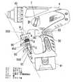
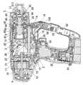
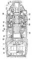
以下、本発明を添付図面に示す実施形態に基いて説明すると、図示例の電動工具は出力ビットに回転に加えて軸方向の打撃も加えることができるハンマードリルで且つ出力ビットに回転のみを与える動作モードも備えたものであって、図中9はグリップ部90が一体に垂下形成されたハウジングであり、電池パック91が着脱自在に連結されるグリップ部90下端の前端部とハウジング9の前端との間にはハウジング補強用の連結部92が一体に形成されている。図中93はグリップ部90の根元部分に配設されたトリガースイッチであり、ハウジング9の後端部内に配設されたモータ19はこのトリガースイッチ93の操作でオンオフされ、また回転方向切換レバー94の操作によってモータ19の回転方向が切り換えられる。  DETAILED DESCRIPTION OF THE PREFERRED EMBODIMENTS The present invention will be described below with reference to the embodiments shown in the accompanying drawings. The power tool in the illustrated example is a hammer drill that can apply not only rotation to the output bit but also axial hitting, and only gives rotation to the output bit. The operation mode is also provided. In the figure,reference numeral 9 denotes a housing in which thegrip portion 90 is integrally suspended. The front end portion of the lower end of thegrip portion 90 to which thebattery pack 91 is detachably connected and the front end of thehousing 9 are provided. A connectingportion 92 for reinforcing the housing is integrally formed therebetween. In the figure,reference numeral 93 denotes a trigger switch disposed at the base portion of thegrip portion 90, and themotor 19 disposed in the rear end portion of thehousing 9 is turned on / off by the operation of thetrigger switch 93 and the rotation direction switching lever 94. The rotation direction of themotor 19 is switched by this operation.

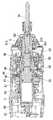
上記モータ19の出力軸10にギア11,12を介して接続された中間軸13は、その先端にピニオン14が一体に形成されているとともに、軸方向中間部に運動方向変換部材2が配されている。この運動変換部材2は、中間軸13に遊転自在に取り付けられた回転部20と、この回転部20の傾斜している外面に遊転自在に取り付けられた外輪21と、外輪21から突出するロッド22とからなるもので、ロッド22はシリンダー3内を軸方向に可動となっているピストン30に連結されている。  Theintermediate shaft 13 connected to theoutput shaft 10 of themotor 19 viagears 11 and 12 is integrally formed with apinion 14 at the tip thereof, and the motiondirection conversion member 2 is disposed at the axial intermediate portion. ing. Themotion converting member 2 protrudes from theouter ring 21, a rotatingpart 20 that is freely mounted on theintermediate shaft 13, anouter ring 21 that is freely mounted on the inclined outer surface of the rotatingpart 20, and theouter ring 21. Therod 22 is connected to apiston 30 that is movable in the axial direction in thecylinder 3.

また上記中間軸13には回転部20との間で噛み合いクラッチを構成するカラー15を中間軸13と一体に回転し且つ中間軸13に対して軸方向スライドとなるように設けている。このカラー15は、ばね16によって回転部20に向けて付勢されることで回転部20と噛み合って中間軸13の回転を回転部20に伝えるものであり、そして回転部20が回転する時、ピストン30との連結で中間軸13の軸回りの回転が規制されているロッド22及び外輪21は揺動を行う。この結果、ピストン30はその軸方向に往復駆動される。  Theintermediate shaft 13 is provided with acollar 15 that meshes with the rotatingportion 20 and constitutes a clutch so as to rotate integrally with theintermediate shaft 13 and slide in the axial direction with respect to theintermediate shaft 13. Thecollar 15 is urged toward the rotatingportion 20 by thespring 16 to mesh with the rotatingportion 20 and transmit the rotation of theintermediate shaft 13 to the rotatingportion 20, and when therotating portion 20 rotates, Therod 22 and theouter ring 21 whose rotation about the axis of theintermediate shaft 13 is restricted by the connection with thepiston 30 swings. As a result, thepiston 30 is driven to reciprocate in the axial direction.

上記カラー15は、ハウジング9の側面に配された切換ハンドル7(図1参照)を操作する時、ばね16に抗して前進して回転部20との噛み合いが外れる。この時には回転部20に回転が伝達されないために、ピストン30が往復動を行うこともない。  When operating the switching handle 7 (see FIG. 1) disposed on the side surface of thehousing 9, thecollar 15 moves forward against thespring 16 and disengages from the rotatingportion 20. At this time, since the rotation is not transmitted to the rotatingunit 20, thepiston 30 does not reciprocate.

上記シリンダー3はその軸回りの回転が自在となっており、その外周面には前記中間軸13のピニオン14と噛み合うギアを備えた回転体40がシリンダー3の軸方向にスライド自在に且つシリンダー3に対して遊転自在に配されているとともに、回転体40の片側に位置するクラッチ板41が固定されている。  Thecylinder 3 is rotatable about its axis, and a rotatingbody 40 having a gear meshing with thepinion 14 of theintermediate shaft 13 is slidable in the axial direction of thecylinder 3 on the outer peripheral surface thereof. And aclutch plate 41 located on one side of the rotatingbody 40 is fixed.

そしてリング状の上記回転体40には、軸方向に貫通する孔が複数個設けられて各孔内に鋼球42が配されている。また、この鋼球42にはスラスト板44を介してクラッチばね45が接しており、クラッチばね45による付勢で鋼球42は上記クラッチ板41に形成された円錐状の係合凹部に係合している。  The ring-shaped rotatingbody 40 is provided with a plurality of axially penetrating holes, and asteel ball 42 is disposed in each hole. Further, aclutch spring 45 is in contact with thesteel ball 42 through athrust plate 44, and thesteel ball 42 is engaged with a conical engagement recess formed in theclutch plate 41 by urging by theclutch spring 45. is doing.

回転体40の孔内に保持されている鋼球42がクラッチ板41の係合凹部に係合している時、シリンダー3の軸回りの回転について、回転体40がクラッチ板41と一体に回転する状態となっているものであり、このために中間軸13の回転は回転体40からクラッチ板41を通じてシリンダー30に伝達される。上記クラッチばね45の他端はシリンダー3の外周に配した可動プレート46によって受けている。この可動プレート46はクラッチハンドル48の回転によってシリンダー3の軸方向に移動してクラッチばね45の圧縮量を変化させる。  When thesteel ball 42 held in the hole of the rotatingbody 40 is engaged with the engaging recess of theclutch plate 41, the rotatingbody 40 rotates integrally with theclutch plate 41 with respect to the rotation of thecylinder 3 around the axis. Therefore, the rotation of theintermediate shaft 13 is transmitted from the rotatingbody 40 to thecylinder 30 through theclutch plate 41. The other end of theclutch spring 45 is received by amovable plate 46 disposed on the outer periphery of thecylinder 3. Themovable plate 46 is moved in the axial direction of thecylinder 3 by the rotation of theclutch handle 48 to change the compression amount of theclutch spring 45.

更に回転体40には原動側となる回転体40と被動側となるクラッチ板41とを直結(図4参照)するためのピン8を配設してある。ばね80による付勢でピン8がクラッチ板41側に向けて突出してクラッチ板41と係合する時、回転体40とクラッチ板41とが直結されて回転体40の回転は常にクラッチ板41及びシリンダー3に伝達される。  Further, therotating body 40 is provided with apin 8 for directly connecting therotating body 40 on the driving side and theclutch plate 41 on the driven side (see FIG. 4). When thepin 8 protrudes toward theclutch plate 41 by the urging force of thespring 80 and engages with theclutch plate 41, therotating body 40 and theclutch plate 41 are directly connected, and the rotation of therotating body 40 is always theclutch plate 41 and It is transmitted to thecylinder 3.

なお、上記の直結用のピン8は、シリンダー3の外周に軸方向スライド自在に配した切換板81がばね85による付勢で前進している時、図2に示すようにピン8の先端面を回転体40とクラッチ板41との境界面に位置させるために直結状態が解除される。切換板81は上記カラー15が回転部20と噛み合う内に移動する時、カラー15に押されてばね85に抗して後退することで、回転体40とクラッチ板41とがピン8で直結された状態に戻す。  Note that when theswitching plate 81 that is slidably disposed in the axial direction on the outer periphery of thecylinder 3 is advanced by the bias of the spring 85, thepin 8 for direct connection as shown in FIG. Is positioned at the boundary surface between the rotatingbody 40 and theclutch plate 41, the direct connection state is released. Theswitching plate 81 is pushed by thecollar 15 and retracts against the spring 85 when thecollar 15 moves while meshing with the rotatingportion 20, so that therotating body 40 and theclutch plate 41 are directly connected by thepin 8. Return to the state.

シリンダー30の軸方向前端にはスピンドル5がシリンダー30と一体に回転するように取り付けられている。このスピンドル5は、その軸方向前端部が出力ビット50を保持するチャック部51となっている。SDSプラス型シャンクに対応した該チャック部51は、抜け止め用のボール510と、回転伝達用の図3に示す内部突条511とを備えたもので、出力ビット50を一体に回転するように且つ出力ビット50を所定量だけ軸方向スライド自在となるように保持する。  Aspindle 5 is attached to the front end in the axial direction of thecylinder 30 so as to rotate integrally with thecylinder 30. Thespindle 5 has achuck portion 51 that holds anoutput bit 50 at its front end in the axial direction. Thechuck portion 51 corresponding to the SDS plus type shank is provided with aball 510 for retaining and aninternal protrusion 511 shown in FIG. 3 for transmitting rotation so as to rotate theoutput bit 50 integrally. Further, theoutput bit 50 is held so as to be slidable in the axial direction by a predetermined amount.

また、前記ピストン30はその後端が閉じられるとともに前端が開放された筒状として形成されてその中には打撃子35がスライド自在に納められている。この打撃子35は、ピストン30が往復動を行う時、ピストン30内の打撃子35で閉じられた空間の空気をばねとしつつ往復動を行って、スピンドル5内に軸方向スライド自在に保持されている中間子52を介して前記出力ビット50に軸方向打撃を与える。図中56はスピンドル5内の中間子52の後方への抜け止めのためのボールである。Thepiston 30 is formed in a cylindrical shape with the rear end closed and the front end open, and astriker 35 is slidably accommodated therein. When thepiston 30 reciprocates, thestriking element 35 is reciprocated while using the air in the space closed by thestriking element 35 in thepiston 30 as a spring, and is held in thespindle 5 so as to be slidable in the axial direction. Theoutput bit 50 is subjected to an axial blow through theintermediate element 52. In the figure,reference numeral 56 denotes a ball for preventing theintermediate member 52 in thespindle 5 from coming outbackward .

図2及び図3は、打撃を伴わない非打撃動作モード状態、つまりねじ締めに供するための状態を示しており、前記切換ハンドル7の操作でカラー15を前進させることでカラー15と回転部20との噛み合いを外すとともに、カラー15のフランジ部150による切換板21の押圧の解除で切換板21がばね85による付勢で前進して直結用のピン8を押し戻して、回転体40とクラッチ板41との間のピン8による直結を解除した状態とするために、中間軸13のピニオン14からの回転が伝えられる回転体40は、鋼球42を介してクラッチ板41、そしてシリンダー3からスピンドル5へと伝えられる。この時、打撃子35はスピンドル5の後端内周面に配したOリング58が先端部外周面に弾性的に係合することで、軸方向に可動となっている打撃子35(並びに中間子52)の軸方向動作が防がれた状態となり、これらが無用な動きをすることがない。  FIGS. 2 and 3 show a non-hitting operation mode state that is not accompanied by striking, that is, a state for use in screw tightening. Thecollar 15 and the rotatingunit 20 are moved forward by operating theswitching handle 7. And the switchingplate 21 is moved forward by the bias of the spring 85 by releasing the pressing of the switchingplate 21 by theflange portion 150 of thecollar 15 to push back thedirect connection pin 8, and therotating body 40 and the clutch plate In order to achieve a state in which the direct connection with thepin 8 with respect to thepin 41 is released, the rotatingbody 40 to which the rotation of theintermediate shaft 13 from thepinion 14 is transmitted via thesteel ball 42 to theclutch plate 41 and from thecylinder 3 to the spindle It is told to 5. At this time, thestriker 35 is movable in the axial direction by the O-ring 58 disposed on the inner peripheral surface of the rear end of thespindle 5 being elastically engaged with the outer peripheral surface of the tip portion (and the intermediate member). The axial movement of 52) is prevented, and these do not move unnecessarily.

この打撃を伴わない状態にセットした時、回転のみを行う出力ビット5で例えばビスなどの締め付け作業を行えば、その負荷トルクがクラッチばね45によるところの鋼球42とクラッチ板41の係合凹所との係合力より強くなると、鋼球42が係合凹所から抜け出して回転体40からクラッチ板41(シリンダー3)への回転伝達が遮断されるために、締め付けトルクは制限される。  If the tightening operation such as a screw is performed with theoutput bit 5 that performs only rotation when set in a state not accompanied by this impact, the engagement torque between thesteel ball 42 and theclutch plate 41 where the load torque is caused by theclutch spring 45 is reduced. When the engagement force with the place becomes stronger, thesteel ball 42 comes out of the engagement recess and the rotation transmission from the rotatingbody 40 to the clutch plate 41 (cylinder 3) is interrupted, so that the tightening torque is limited.

この締め付けトルクは、前述のようにクラッチハンドル48を回転させて可動プレート46を後退させることでクラッチばね45の圧縮量を増大させることによって大きくすることができる。つまり、回転体40とクラッチ板41とが鋼球42や可動プレート46やクラッチばね45等とともに締め付けトルク調整用クラッチ4を構成しているものである。そして、クラッチハンドル48の操作でクラッチばね45を最大限に圧縮した時は、鋼球42がクラッチ板41の係合凹所から抜け出すことがない状態となるために、いわゆるドリル作業に適した状態となる。  This tightening torque can be increased by increasing the compression amount of theclutch spring 45 by rotating theclutch handle 48 and moving themovable plate 46 backward as described above. That is, the rotatingbody 40 and theclutch plate 41 constitute the tightening torque adjusting clutch 4 together with thesteel balls 42, themovable plate 46, theclutch spring 45, and the like. When theclutch spring 45 is compressed to the maximum by operating theclutch handle 48, thesteel ball 42 does not come out of the engagement recess of theclutch plate 41. It becomes.

また、切換ハンドル7の操作でカラー15を後退させて回転部20に噛み合わせた図4及び図5に示す状態では、カラー15によって切換板81がばね85に抗して後退させられることから、直結用のピン8による回転体40とクラッチ板41との間の直結がなされる。従って、運動変換部材2によるピストン2の往復駆動と、シリンダー3及びスピンドル5の回転駆動が常時なされる打撃動作モード状態となる。更にこの時には、出力ビット50を被穿孔面に押し当てた時の出力ビット50の後退で中間子52も後退するとともに、Oリング58による保持位置よりも打撃子35を後方へ押し出してしまうために、ピストン30の往復動で打撃子35も往復動を行って、打撃子35が中間子52を介して出力ビット50に軸方向打撃を与える状態となる。このために出力ビット50には回転が伝達されると同時に軸方向打撃が与えられる。  Further, in the state shown in FIGS. 4 and 5 in which thecollar 15 is moved backward by the operation of theswitching handle 7 and meshed with the rotatingportion 20, the switchingplate 81 is moved backward against the spring 85 by thecollar 15. The rotatingbody 40 and theclutch plate 41 are directly connected by the directly connectingpin 8. Therefore, the striking operation mode state in which the reciprocating drive of thepiston 2 by themotion converting member 2 and the rotational drive of thecylinder 3 and thespindle 5 are always performed. Further, at this time, theoutput bit 50 is pressed against the drilled surface, theintermediate bit 52 is also moved backward by theoutput bit 50 and thestriker 35 is pushed backward from the holding position by the O-ring 58. Thestriking element 35 is also reciprocated by the reciprocating movement of thepiston 30, and thestriking element 35 is in a state of giving an axial striking to theoutput bit 50 via theintermediate element 52. For this reason, the rotation is transmitted to theoutput bit 50 and at the same time an axial blow is given.

なお、切換ハンドル7は回転部20との噛み合いが外れる方向にカラー15を駆動するものであり、回転部20と噛み合う方向への移動は回転部20との噛み合いをスムーズに得られるようにするためにカラー15を付勢するばね16によるものとしていることから、このばね16の力を切換板81を付勢するばね82の力よりも強くしている。また、ばね82の力は直結用ピン8を付勢するばね80の力よりも強くしている。  The switching handle 7 drives thecollar 15 in a direction in which the meshing with the rotatingunit 20 is disengaged, and the movement in the direction in which the meshing with the rotatingunit 20 is meshed with the rotatingunit 20 can be smoothly achieved. Since thespring 16 that biases thecollar 15 is used, the force of thespring 16 is made stronger than the force of thespring 82 that biases the switchingplate 81. The force of thespring 82 is stronger than the force of thespring 80 that biases thedirect connection pin 8.

ところで、ドリルビットやドライバービットといった出力ビット50は、ハンマードリル用のSDSプラス型シャンクを持たないために、前述のようにSDSプラス型シャンクを有するアダプター50’を介して装着することになるのであるが、このアダプター50’は通常のSDSプラス型シャンク(図6(b)参照)と少し異なるものを用いている。  By the way, since theoutput bit 50 such as the drill bit or the driver bit does not have the SDS plus type shank for the hammer drill, it is attached through theadapter 50 ′ having the SDS plus type shank as described above. However, thisadapter 50 ′ is a little different from a normal SDS plus type shank (see FIG. 6B).

すなわち、図6(a)に示すように、前記抜け止め用のボール510が嵌り込む溝500と、前記回転伝達用の内部突条511がスライド係合するスライド溝501とをアダプター50’に設けている点では通常のSDSプラス型シャンクと同じであるが、このスライド溝501のシャンク後端からの軸方向長さを短くしている。つまり、アダプター50’をチャック部51に装着しても、内部突条511との係合で差し込み量が制限されて、中間子52の先端面にアダプター50’の後端が当接する位置までアダプター50’が後退することがないようにしている。  That is, as shown in FIG. 6 (a), the adapter 50 'is provided with agroove 500 into which the retainingball 510 is fitted and aslide groove 501 in which theinternal ridge 511 for rotation transmission is slidably engaged. However, the length of theslide groove 501 in the axial direction from the rear end of the shank is shortened. That is, even when theadapter 50 ′ is mounted on thechuck portion 51, the insertion amount is limited by the engagement with theinternal protrusion 511, and theadapter 50 is moved to a position where the rear end of theadapter 50 ′ comes into contact with the tip surface of theintermediate element 52. 'I'm trying not to retreat.

このために回転と打撃とが与えられるハンマードリルモード(打撃動作モード)に設定した状態のままでアダプター50’を介してドリルビットやドライバービットといった出力ビット50を装着しても、打撃がアダプター50’に加えられることがなく、打撃振動でアダプター50’やドリルビットやドライバービットといった出力ビット50、更には該出力ビット50の先端が当接しているねじ等を破損させてしまうことがないものである。ちなみに、Oリング58によって打撃子35が保持される状態も上記の理由で保たれる。  For this reason, even if anoutput bit 50 such as a drill bit or a driver bit is attached via theadapter 50 ′ in a state in which the hammer drill mode (blow operation mode) in which rotation and blow are applied is set, the blow is applied to theadapter 50. It is not added to 'and does not damage the adapter 50', theoutput bit 50 such as a drill bit or a driver bit, and the screw with which the tip of theoutput bit 50 abuts due to the impact vibration. is there. Incidentally, the state in which thestriker 35 is held by the O-ring 58 is also maintained for the above reason.

もちろん、チャック部51に装着する出力ビット50が図6(b)に示す通常のSDSプラス型シャンクを有するハンマードリルビットである場合には、出力ビット50の後端が中間子52に当接する位置まで後退可能な状態に保持されるものであり、また中間子52を介して打撃子35を前述のOリング58による保持位置よりも後方に押し戻すことができる状態となるために、出力ビット50には回転に加えて打撃振動が加えられる。  Of course, when theoutput bit 50 attached to thechuck portion 51 is a hammer drill bit having a normal SDS plus type shank as shown in FIG. 6B, the rear end of theoutput bit 50 reaches a position where it abuts against theintermediate element 52. Theoutput bit 50 is rotated so that thestriker 35 is held in a retractable state and thestriker 35 can be pushed back from the holding position by the O-ring 58 via theintermediate element 52. In addition to the impact vibration.

アダプター50’におけるスライド溝501は長さだけでなく端部の処理も変更しているが、これは内部突条511の端部が平坦な傾斜面となっていて、この端部が図6(b)に示す形状のスライド溝501の端部に当たれば、端部の両側縁のみが当たってスライド溝501の端部が削れてしまうことになるためで、内部突条511の上記端部を面で受けることができる傾斜面502を構成するように処理している。  Theslide groove 501 in theadapter 50 ′ is changed not only in length but also in the processing of the end portion. This is because the end portion of theinner protrusion 511 is a flat inclined surface, and this end portion is shown in FIG. If it hits the end of theslide groove 501 having the shape shown in b), only both side edges of the end will hit and the end of theslide groove 501 will be scraped. It is processed to form aninclined surface 502 that can be received by the surface.

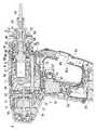
ここにおいて、上記アダプター50’を使用しない時、ハウジング9における連結部92に設けたホルダー部95に収納しておくことができるようにしてある。このホルダー部95は、図1及び図7に示すように、連結部92の一側方に開口する凹所として形成されたもので、シャンク部を保持するばね板950と、アダプター50’の大径となっているチャック部を納める拡大凹所952、そしてアダプター50’に出力ビット50が取り付けられたままの状態の時にその出力ビット50を納める空所953で構成されている。  Here, when theadapter 50 ′ is not used, theadapter 50 ′ can be stored in theholder portion 95 provided in the connectingportion 92 of thehousing 9. As shown in FIGS. 1 and 7, theholder portion 95 is formed as a recess that opens to one side of the connectingportion 92, and is alarge spring plate 950 that holds the shank portion and alarge adapter 50 ′. Anenlarged recess 952 for accommodating the chuck portion having a diameter and avoid 953 for accommodating theoutput bit 50 when theoutput bit 50 is still attached to theadapter 50 ′.

また、上記拡大凹所952の他の側方には、連結部92の厚みを薄くすることで上記アダプター50’を取り出す時にチャック部に指を掛けることができるようにするための空間951を設けている。この空間951は、連結部92におけるグリップ部90側の面に設けると同時に、空間951は連結部92の中程で前記トリガースイッチ93と対面しないところに配してある。  In addition, aspace 951 is provided on the other side of theenlarged recess 952 so that a finger can be placed on the chuck portion when theadapter 50 ′ is taken out by reducing the thickness of the connectingportion 92. ing. Thespace 951 is provided on the surface of the connectingportion 92 on thegrip portion 90 side, and at the same time, thespace 951 is arranged in the middle of the connectingportion 92 so as not to face thetrigger switch 93.

空間951の存在により、アダプター50’に指を掛けて側方に開口するホルダー部95から取り出すことが容易に行えるようになっているものであり、特に側方に開口する凹所として形成されているホルダー部95からアダプター50’を取り出す方向に力を加えることができるために、打撃振動による脱落を防ぐために保持用のばね板950のばね力を強くしても、アダプター50’の取り外しを容易に行うことができる。しかも電動工具のグリップ部90を握るとともにトリガースイッチ93に指を掛けた状態においても、他方の手の指を空間951に入れることができるために、アダプター50’を取り外しが困難となることはない。  Due to the presence of thespace 951, theadapter 50 ′ can be easily taken out from theholder portion 95 that opens to the side by placing a finger, and is formed as a recess that opens to the side. Since it is possible to apply a force in the direction of taking out theadapter 50 ′ from theholder portion 95, theadapter 50 ′ can be easily removed even if the spring force of the holdingspring plate 950 is increased to prevent theadapter 50 ′ from falling off due to impact vibration. Can be done. Moreover, even when thegrip part 90 of the electric tool is gripped and the finger is put on thetrigger switch 93, the finger of the other hand can be put into thespace 951, so that it is not difficult to remove the adapter 50 '. .

出力ビット50を装着したままのアダプター50’をホルダー部95に収納する際は、図7(d)に示すように出力ビット50の先端を空所953に差し込んでからアダプター50を拡大凹所952に納めるとともにシャンク部をばね板950の配設部に押し込むことで行う。取り出しは逆の操作で行う。もっとも、この取り出し時には、出力ビット50が連結部92の図7(d)に示す側壁端縁部955に当たり、この部分を削ったり破損してしまうことになる虞があることから、図9に示すように補強リブ954を側壁に設けておくことが好ましい。また、出力ビット50の先端に弾接することになるクッション材956を空所953の奥端に配置しておけば、打撃振動が加わった時にも出力ビット50の先端がハウジング9内面を傷つけたり騒音を出したりすることがなくて好ましい。  When theadapter 50 ′ with theoutput bit 50 attached is accommodated in theholder 95, theadapter 50 is expanded into the recessedportion 952 after inserting the tip of theoutput bit 50 into thespace 953 as shown in FIG. 7 (d). And the shank part is pushed into the arrangement part of thespring plate 950. The removal is performed in the reverse operation. However, since theoutput bit 50 hits theside wall edge 955 shown in FIG. 7 (d) of the connectingportion 92 at the time of taking out, there is a possibility that this portion will be scraped or damaged, so that it is shown in FIG. Thus, it is preferable to provide the reinforcingrib 954 on the side wall. Further, if acushion material 956 that is elastically contacted with the tip of theoutput bit 50 is disposed at the back end of thespace 953, the tip of theoutput bit 50 may damage the inner surface of thehousing 9 even when impact vibration is applied. It is preferable that it does not give out.

なお、上記連結部92はハウジング9におけるクラッチハンドル48よりも後方に位置するところからいったん斜め前方側に突出させた後、グリップ部90の下端に繋がるようにしているが、これはグリップ部90と連結部92との間にグリップ部90を握る手と空所951に指を入れることができるスペースとを確保しつつ、電池パック91の下端とチャック部51の先端部とをつなぐ線(図1参照)よりも連結部92が前方に出ることがないようにするためであり、これによって前方側へ転倒させた時に連結部92が衝撃で破損してしまったり、衝撃でホルダー部95からアダプター50’が脱落してしまうことを防いでいる。  The connectingportion 92 is once protruded obliquely forward from a position behind theclutch handle 48 in thehousing 9 and then connected to the lower end of thegrip portion 90. A line connecting the lower end of thebattery pack 91 and the tip of thechuck portion 51 while securing a hand for gripping thegrip portion 90 between the connectingportion 92 and a space where a finger can be inserted into the space 951 (FIG. 1). For example, the connectingportion 92 may be damaged by an impact when it falls down forward, or theadapter 50 may be removed from theholder portion 95 by an impact. 'Prevents it from falling off.

以上の実施例では、ホルダー部95に装着するものをアダプター50’で説明したが、出力ビット50を直接ホルダー部95に装着することもできる。ただし、図示例においては、ハンマードリルとして使用する際に用いるコンクリートドリルビットについては、ホルダー部95に装着すると拡大凹所952おいて鋭利なエッジが露出することになって危険であることから、ホルダー部95の全長をコンクリートドリルビットの全長よりも短くすることで、コンクリートドリルビットはホルダー部95に装着できないようにしている。  In the above embodiment, theadapter 50 ′ has been described as being attached to theholder portion 95, but theoutput bit 50 can also be directly attached to theholder portion 95. However, in the illustrated example, the concrete drill bit used when used as a hammer drill is dangerous because a sharp edge is exposed in theenlarged recess 952 when it is attached to theholder portion 95. By making the overall length of theportion 95 shorter than the overall length of the concrete drill bit, the concrete drill bit cannot be attached to theholder portion 95.

本発明の実施の形態の一例の側面図である。It is a side view of an example of an embodiment of the invention.同上の打撃を伴わないモードにセットした状態の縦断面図である。It is a longitudinal cross-sectional view of the state set to the mode which does not accompany a blow same as the above.同上の打撃を伴わないモードにセットした状態の水平断面図である。It is a horizontal sectional view of the state set to the mode which is not accompanied by a blow same as the above.同上の打撃を伴うモードにセットした状態の縦断面図である。It is a longitudinal cross-sectional view of the state set to the mode accompanied by a hit same as the above.同上の打撃を伴うモードにセットした状態の水平断面図である。It is a horizontal sectional view of the state set to the mode accompanied by the same as above.(a)はアダプターの斜視図、(b)は通常のシャンク形状を示す斜視図である。(a) is a perspective view of an adapter, (b) is a perspective view showing a normal shank shape.(a)(b)(c)(d)は夫々図1中のA−A線断面図とB−B線断面図とC−C線断面図とD−D線断面図である。(a), (b), (c), and (d) are an AA line sectional view, a BB line sectional view, a CC line sectional view, and a DD line sectional view in FIG. 1, respectively.同上の締め付けトルク調整用クラッチ部分の分解斜視図である。It is a disassembled perspective view of the clutch part for fastening torque adjustment same as the above.他例の部分断面図である。It is a fragmentary sectional view of other examples.

符号の説明Explanation of symbols

50’ アダプター
50 出力ビット
51 チャック部
52 中間子(打撃用部材)
500 溝
501 スライド溝
50 'adapter 50output bit 51chuck part 52 meson (member for striking)
500groove 501 slide groove

Claims (6)

Translated fromJapanese
チャック部に装着される出力ビット及び/またはアダプターを保持することができるホルダー部を備えた電動工具であり、チャック部が配されたハウジング先端側と、ハウジングから垂下されているグリップ部との間を連結している連結部を有して該連結部に上記ホルダー部が連結部の側方に開口する凹所として形成されているとともに、該ホルダー部で保持された出力ビット及び/またはアダプターに隣接して指入れ用の空間が上記連結部のグリップ部がわの面に設けられていることを特徴とする電動工具。An electric tool having a holder part that can hold an output bit and / or an adapter attached to the chuck part, between the front end side of the housing where the chuck part is arranged and the grip part hanging from the housing together with the holder in the connecting portion has a connecting portion which connectsis formed as a recess that opens to the side of the connecting portion, the output bit and / or adapter held by the holder portion An electric tool characterized in that a space for finger insertion is provided adjacent tothe grip portion of the connecting portion onthe side of the hook.上記空間がグリップ部の根元に配されたオンオフ用トリガースイッチと対向しない位置に設けられていることを特徴とする請求項1記載の電動工具。2. The electric tool according to claim 1, wherein the space is provided at a position not facing an on / off trigger switch disposed at the base of the grip portion.ホルダー部は出力ビット装着用のチャック部を備えているアダプターの保持用であり且つアダプターに装着された出力ビットを収納する空所を連結部内部に備えていることを特徴とする請求項1または2に記載の電動工具。The holder part is for holding an adapter having a chuck part for mounting an output bit, and has a space inside the connecting part for storing an output bit attached to the adapter. 2. The electric tool according to 2.出力ビット先端が弾接するクッション材を空所の奥端に備えていることを特徴とする請求項3記載の電動工具。4. The electric tool according to claim 3, further comprising a cushion material that elastically contacts the tip of the output bit at the back end of the space.空所の内壁に出力ビット外面に当接する補強リブを備えていることを特徴とする請求項3または4記載の電動工具。The power tool according to claim 3 or 4, further comprising a reinforcing rib that abuts against an outer surface of the output bit on an inner wall of the space.連結部はグリップ部の下端に装着される電池パックの下端と前記チャック部とを結ぶ線よりもグリップ部がわにあることを特徴とする請求項1〜5のいずれか1項に記載の電動工具。The electric connecting device according to any one of claims 1 to 5, wherein the connecting portion has a grip portion at a side of a line connecting a lower end of a battery pack attached to a lower end of the grip portion and the chuck portion. tool.
JP2005357009A2005-12-092005-12-09 Electric toolActiveJP4458035B2 (en)

Priority Applications (1)

Application NumberPriority DateFiling DateTitle
JP2005357009AJP4458035B2 (en)2005-12-092005-12-09 Electric tool

Applications Claiming Priority (1)

Application NumberPriority DateFiling DateTitle
JP2005357009AJP4458035B2 (en)2005-12-092005-12-09 Electric tool

Publications (2)

Publication NumberPublication Date
JP2007160419A JP2007160419A (en)2007-06-28
JP4458035B2true JP4458035B2 (en)2010-04-28

Family

ID=38243900

Family Applications (1)

Application NumberTitlePriority DateFiling Date
JP2005357009AActiveJP4458035B2 (en)2005-12-092005-12-09 Electric tool

Country Status (1)

CountryLink
JP (1)JP4458035B2 (en)

Also Published As

Publication numberPublication date
JP2007160419A (en)2007-06-28

Similar Documents

PublicationPublication DateTitle
EP1795311A2 (en)Power impact tool
US7694750B2 (en)Hammer drill
JP4898249B2 (en) Work tools
EP1795307A2 (en)Power impact tool adapter
JP6325360B2 (en) Impact tool
US20100155094A1 (en)Impact tool
US7296635B2 (en)Rotary hammer with mode change ring
JP2012254513A (en)Impact tool
CN100420531C (en) hammer drill
US20090065228A1 (en)Power impact tool
JP2828657B2 (en) Hammer drill
JP4458035B2 (en) Electric tool
WO2012144568A1 (en)Impact tool
US20230390911A1 (en)Universal Chisel Attachment
US20170087705A1 (en)Clutch device and power tool with clutch device
JP2009241228A (en)Hammer
JP4405378B2 (en) Electric tool
JP5426197B2 (en) Impact tool
JP4664253B2 (en) Impact tool
JP6271363B2 (en) Medical screwdriver
JP4458018B2 (en) Impact tool
JP4746920B2 (en) Electric tool
JP2006187836A (en)Hammer drill
JP2014024166A (en)Power tool and tip tool
JP2007326193A (en) Impact tool

Legal Events

DateCodeTitleDescription
A621Written request for application examination

Free format text:JAPANESE INTERMEDIATE CODE: A621

Effective date:20071109

A977Report on retrieval

Free format text:JAPANESE INTERMEDIATE CODE: A971007

Effective date:20091015

A131Notification of reasons for refusal

Free format text:JAPANESE INTERMEDIATE CODE: A131

Effective date:20091020

A521Written amendment

Free format text:JAPANESE INTERMEDIATE CODE: A523

Effective date:20091221

TRDDDecision of grant or rejection written
A01Written decision to grant a patent or to grant a registration (utility model)

Free format text:JAPANESE INTERMEDIATE CODE: A01

Effective date:20100119

A01Written decision to grant a patent or to grant a registration (utility model)

Free format text:JAPANESE INTERMEDIATE CODE: A01

A61First payment of annual fees (during grant procedure)

Free format text:JAPANESE INTERMEDIATE CODE: A61

Effective date:20100201

R151Written notification of patent or utility model registration

Ref document number:4458035

Country of ref document:JP

Free format text:JAPANESE INTERMEDIATE CODE: R151

FPAYRenewal fee payment (event date is renewal date of database)

Free format text:PAYMENT UNTIL: 20130219

Year of fee payment:3

FPAYRenewal fee payment (event date is renewal date of database)

Free format text:PAYMENT UNTIL: 20130219

Year of fee payment:3

FPAYRenewal fee payment (event date is renewal date of database)

Free format text:PAYMENT UNTIL: 20140219

Year of fee payment:4


[8]ページ先頭

©2009-2025 Movatter.jp