Movatterモバイル変換


[0]ホーム

URL:


JP4457885B2 - Switch with dimming function - Google Patents

Switch with dimming function
Download PDF

Info

Publication number
JP4457885B2
JP4457885B2JP2004372200AJP2004372200AJP4457885B2JP 4457885 B2JP4457885 B2JP 4457885B2JP 2004372200 AJP2004372200 AJP 2004372200AJP 2004372200 AJP2004372200 AJP 2004372200AJP 4457885 B2JP4457885 B2JP 4457885B2
Authority
JP
Japan
Prior art keywords
signal
dimming
switch
lamp
piano handle
Prior art date
Legal status (The legal status is an assumption and is not a legal conclusion. Google has not performed a legal analysis and makes no representation as to the accuracy of the status listed.)
Expired - Fee Related
Application number
JP2004372200A
Other languages
Japanese (ja)
Other versions
JP2006179350A (en
Inventor
敏昭 時実
修次 松浦
Current Assignee (The listed assignees may be inaccurate. Google has not performed a legal analysis and makes no representation or warranty as to the accuracy of the list.)
Panasonic Corp
Panasonic Electric Works Co Ltd
Original Assignee
Panasonic Corp
Matsushita Electric Works Ltd
Priority date (The priority date is an assumption and is not a legal conclusion. Google has not performed a legal analysis and makes no representation as to the accuracy of the date listed.)
Filing date
Publication date
Application filed by Panasonic Corp, Matsushita Electric Works LtdfiledCriticalPanasonic Corp
Priority to JP2004372200ApriorityCriticalpatent/JP4457885B2/en
Priority to TW094145018Aprioritypatent/TWI278587B/en
Priority to KR1020050126847Aprioritypatent/KR100749997B1/en
Priority to SA05260431Aprioritypatent/SA05260431B1/en
Priority to CNB2005100229793Aprioritypatent/CN100419931C/en
Publication of JP2006179350ApublicationCriticalpatent/JP2006179350A/en
Application grantedgrantedCritical
Publication of JP4457885B2publicationCriticalpatent/JP4457885B2/en
Anticipated expirationlegal-statusCritical
Expired - Fee Relatedlegal-statusCriticalCurrent

Links

Images

Classifications

Landscapes

Description

Translated fromJapanese

本発明は、調光機能付スイッチに関するものである。  The present invention relates to a switch with a dimming function.

従来より、図18に示すように取付枠4を用いて壁材に埋込配設される器体81の前面に回転ダイヤル82を備え、回転ダイヤル82の回転操作に応じて白熱灯(図示せず)に供給する交流電圧の位相角を変化させて、白熱灯を調光点灯させる調光機能付スイッチ80が提供されている(例えば特許文献1参照)。尚、図18中の83は調光機能付スイッチ80とともに取付枠4に並設されたスイッチであり、このスイッチ83のオン/オフ操作に応じて白熱灯への電源供給がオン/オフされる。
特開2002−75711号公報
Conventionally, as shown in FIG. 18, arotary dial 82 is provided on the front surface of acontainer 81 that is embedded in a wall material using themounting frame 4, and an incandescent lamp (not shown) is provided according to the rotation operation of therotary dial 82. A switch 80 with a dimming function for dimming and lighting an incandescent lamp by changing the phase angle of the AC voltage supplied to the device (see, for example, Patent Document 1). Note thatreference numeral 83 in FIG. 18 denotes a switch arranged in parallel with themounting frame 4 together with the dimming function switch 80, and the power supply to the incandescent lamp is turned on / off in accordance with the on / off operation of theswitch 83. .
JP 2002-75711 A

上記構成の調光機能付スイッチ80は壁材に埋込配設されているため、調光レベルを変化させる場合は、調光機能付スイッチ80の配設されている壁まで行って、調光操作を行わねばならなかった。しかしながら、一般的に調光機能付スイッチ80はテレビの鑑賞時や就寝時に部屋を暗くするというような使われ方をするので、ユーザが今いる場所(テレビの前やベッドなど)で調光操作を行いたいという要望があり、従来の調光機能付スイッチ80では使い勝手が悪いという問題があった。  The dimming function switch 80 having the above-described configuration is embedded in the wall material. Therefore, when changing the dimming level, go to the wall where the dimming function switch 80 is disposed, and adjust the dimming level. I had to do the operation. However, since the switch with dimming function 80 is generally used to darken the room when watching TV or sleeping, the dimming operation is performed in the place where the user is present (in front of the TV or bed). There is a request to perform this, and the conventional switch with dimming function 80 has a problem that it is not easy to use.

本発明は上記問題点に鑑みて為されたものであり、その目的とするところは、手元で調光操作を行えるようにした調光機能付スイッチを提供することにある。  The present invention has been made in view of the above-described problems, and an object of the present invention is to provide a switch with a dimming function that can perform a dimming operation at hand.

上記目的を達成するために、請求項1の発明は、押操作に応じて操作信号を発生する押釦スイッチの押釦、および、外部から送信された赤外線のような光信号よりなるワイヤレス信号を受信する信号受信部が前面側に設けられ、少なくとも前面を室内側に露出させた状態で造営材に固定されるスイッチ本体と、該スイッチ本体の内部に収納され、操作信号および信号受信部の受信信号をもとにランプの点灯出力を制御する制御回路部と、スイッチ本体の前面に揺動自在に取り付けられてピアノタッチ操作で押釦を押圧するピアノハンドルと、手で把持可能な大きさに形成されてピアノハンドルの前面に着脱自在に取り付けられるリモコン本体とを備え、リモコン本体は、ピアノハンドルとの対向面に設けられた調光操作釦と、該調光操作釦の操作に応じた調光信号をワイヤレス信号で送信する信号送信部とを有し、信号受信部がリモコン本体からワイヤレス信号で送信された調光信号を受信すると、制御回路部が調光信号をもとにランプの調光レベルを変化させるとともに、スイッチ本体に、リモコン本体がピアノハンドルに取り付けられているか否かを検知するリモコン装着検知手段を設け、リモコン装着検知手段がリモコン本体の取付状態を検知している場合、制御回路部は、押釦スイッチから操作信号が入力されると、ランプを全点灯させるか又は消灯させ、リモコン装着検知手段がリモコン本体の取外し状態を検知している場合、制御回路部は、押釦スイッチから操作信号が入力されると、ランプを前回調光信号で調整された調光レベルで点灯させるか又は消灯させることを特徴とする。In order to achieve the above object, the invention ofclaim 1 receives a push button of a push button switch that generates an operation signal in response to a push operation, and a wireless signal comprising an optical signal such as infrared rays transmitted from the outside. A signal receiving unit is provided on the front side, and at least the front side is exposed to the indoor side. The switch body is fixed to the construction material, and the operation signal and the reception signal of the signal receiving unit are stored in the switch body. Based on the control circuit unit that controls the lighting output of the lamp, the piano handle that is swingably attached to the front surface of the switch body and presses the push button by the piano touch operation, and has a size that can be gripped by hand. A remote control main body detachably attached to the front surface of the piano handle, the remote control main body comprising: a dimming operation button provided on a surface facing the piano handle; and the dimming operation button A signal transmission unit that transmits a dimming signal according to the operation as a wireless signal, and when the signal receiving unit receives the dimming signal transmitted as a wireless signal from the remote control body, the control circuit unit also receives the dimming signal. In addition, the dimming level of the lamp is changed, and the switch body is provided with remote control wearing detection means for detecting whether the remote control body is attached to the piano handle, and the remote control wearing detection means detects the mounting state of the remote control body. When the operation signal is input from the pushbutton switch, the control circuit unit turns the lamp on or off, and when the remote control attachment detection means detects the removed state of the remote control body, parts, when the operation signal from the push button switch is input, or turning off lights the lamp adjustment dimming levels in the last dimming signal And features.

この発明によれば、造営材に固定されたスイッチ本体の押釦スイッチをピアノハンドルを介して押操作することで、ランプの点灯出力を切り替えることができ、且つ、ピアノハンドルから取り外したリモコン本体を用い、リモコン本体の調光操作釦を操作することで、リモコン本体の信号送信部からワイヤレス信号で調光信号を送信させ、この調光信号をもとに制御回路部がランプの調光レベルを変化させているので、ランプの調光操作を手元で行うことができ、調光操作を行うために造営材に固定されたスイッチ本体の設置位置まで行かなくても済むから、使い勝手が向上するという効果がある。  According to this invention, by pressing the push button switch of the switch body fixed to the construction material through the piano handle, the lighting output of the lamp can be switched, and the remote control body removed from the piano handle is used. By operating the dimming operation button on the remote control unit, the signal transmission unit of the remote control unit transmits a dimming signal with a wireless signal, and the control circuit unit changes the dimming level of the lamp based on this dimming signal As a result, the dimming operation of the lamp can be performed at hand, and it is not necessary to go to the installation position of the switch body fixed to the construction material in order to perform the dimming operation. There is.

また、就寝前やテレビ鑑賞の場面ではオン/オフ操作に応じてランプを調光レベルで点灯又は消灯させ、それ以外の場面ではオン/オフ操作に応じてランプを全点灯又は消灯させることが望ましいが、請求項の発明によれば、リモコン装着検知手段がリモコン本体の取付状態を検知している場合、すなわちリモコン本体が外されておらず、就寝前やテレビの鑑賞中ではないと予想される場合は、ピアノハンドルを介して押釦スイッチの押釦を押操作すると、ランプを全点灯又は消灯させることができ、またリモコン装着検知手段がリモコン本体の取外し状態を検知している場合、すなわち就寝前やテレビの鑑賞中でリモコン本体を外して使用していると予想される場合は、ピアノハンドルを介して押釦スイッチの押釦を押操作すると、ランプを調光点灯又は消灯させることができるから、使い勝手が向上する。In addition , it is desirable that the lamp is turned on or off at a dimming level according to the on / off operation before going to bed or watching TV, and that the lamp is fully turned on or off according to the on / off operation in other situations. However, according to thefirst aspect of the present invention, it is expected that when the remote control attachment detecting means detects the attachment state of the remote control body, that is, the remote control body has not been removed and is not being watched before going to bed or watching TV. When the push button of the push button switch is pressed through the piano handle, the lamp can be turned on or off completely, and the remote control attachment detection means detects the remote controller main body removal state, that is, before going to bed. If you are using the remote control while you are watching or watching TV, press the pushbutton on the pushbutton switch via the piano handle. Since it is possible to dimming lights or is turned off, thereby enhancing usability.

請求項の発明は、押操作に応じて操作信号を発生する押釦スイッチの押釦、および、外部から送信された赤外線のような光信号よりなるワイヤレス信号を受信する信号受信部が前面側に設けられ、少なくとも前面を室内側に露出させた状態で造営材に固定されるスイッチ本体と、該スイッチ本体の内部に収納され、操作信号および信号受信部の受信信号をもとにランプの点灯出力を制御する制御回路部と、スイッチ本体の前面に揺動自在に取り付けられてピアノタッチ操作で押釦を押圧するピアノハンドルと、手で把持可能な大きさに形成されてピアノハンドルの前面に着脱自在に取り付けられるリモコン本体とを備え、リモコン本体は、ピアノハンドルとの対向面に設けられた調光操作釦と、該調光操作釦の操作に応じた調光信号をワイヤレス信号で送信する信号送信部とを有し、信号受信部がリモコン本体からワイヤレス信号で送信された調光信号を受信すると、制御回路部が調光信号をもとにランプの調光レベルを変化させるとともに、押釦スイッチの操作信号が制御回路部に所定の連続押し時間以上連続して入力されると、制御回路部は、操作信号が入力されている間、ランプの調光レベルを上限値と下限値の間で繰り返し増減させることを特徴とする。According to thesecond aspect of the present invention,a push button of a push button switch that generates an operation signal in response to a push operation and a signal receiving unit that receives a wireless signal composed of an optical signal such as infrared rays transmitted from the outside are provided on the front side. A switch body that is fixed to the construction material with at least the front surface exposed to the indoor side, and is housed in the switch body, and the lighting output of the lamp is based on the operation signal and the reception signal of the signal receiving unit. A control circuit unit for control, a piano handle that is swingably attached to the front surface of the switch body and presses a push button by a piano touch operation, and is formed in a size that can be gripped by hand and is detachable on the front surface of the piano handle A remote control body to be mounted, and the remote control body has a dimming operation button provided on the surface facing the piano handle and a dimming signal corresponding to the operation of the dimming operation button. When the signal receiving unit receives a dimming signal transmitted as a wireless signal from the remote control body, the control circuit unit adjusts the dimming level of the lamp based on the dimming signal. When the operation signal ofthe pushbutton switch is continuously input to the control circuit unit for a predetermined continuous pressing time or longer, the control circuit unit sets the dimming level of the lamp to the upper limit value while the operation signal is input. It is characterized by repeatedly increasing and decreasing between and lower limit values.

この発明によれば、造営材に固定されたスイッチ本体の押釦スイッチをピアノハンドルを介して押操作することで、ランプの点灯出力を切り替えることができ、且つ、ピアノハンドルから取り外したリモコン本体を用い、リモコン本体の調光操作釦を操作することで、リモコン本体の信号送信部からワイヤレス信号で調光信号を送信させ、この調光信号をもとに制御回路部がランプの調光レベルを変化させているので、ランプの調光操作を手元で行うことができ、調光操作を行うために造営材に固定されたスイッチ本体の設置位置まで行かなくても済むから、使い勝手が向上するという効果がある。さらに、ピアノハンドルを介して押釦スイッチの押釦を所定の連続押し時間以上連続して押し操作すると、制御回路部は、操作信号が入力されている間、ランプの調光レベルを上限値と下限値の間で繰り返し増減させるので、所望の調光レベルになった時にピアノハンドルを離すことで所望の調光レベルで点灯させることができ、リモコン本体が見当たらない場合でもランプの調光レベルを調整できるという効果がある。According to this invention,by pressing the push button switch of the switch body fixed to theconstruction material through the piano handle, the lighting output of the lamp can be switched, and the remote control body removed from the piano handle is used. By operating the dimming operation button on the remote control unit, the signal transmission unit of the remote control unit transmits a dimming signal with a wireless signal, and the control circuit unit changes the dimming level of the lamp based on this dimming signal As a result, the dimming operation of the lamp can be performed at hand, and it is not necessary to go to the installation position of the switch body fixed to the construction material in order to perform the dimming operation. There is. Further, when the push button of the push button switch is continuously pressed throughthe piano handle for a predetermined continuous pressing time or longer, the control circuit unit sets the dimming level of the lamp to the upper limit value and the lower limit value while the operation signal is input. Since it is repeatedly increased or decreased between the two, the piano can be turned on at the desired dimming level by releasing the piano handle when the desired dimming level is reached, and the dimming level of the lamp can be adjusted even when the remote control unit is not found There is an effect.

請求項の発明は、押操作に応じて操作信号を発生する押釦スイッチの押釦、および、外部から送信された赤外線のような光信号よりなるワイヤレス信号を受信する信号受信部が前面側に設けられ、少なくとも前面を室内側に露出させた状態で造営材に固定されるスイッチ本体と、該スイッチ本体の内部に収納され、操作信号および信号受信部の受信信号をもとにランプの点灯出力を制御する制御回路部と、スイッチ本体の前面に揺動自在に取り付けられてピアノタッチ操作で押釦を押圧するピアノハンドルと、手で把持可能な大きさに形成されてピアノハンドルの前面に着脱自在に取り付けられるリモコン本体とを備え、リモコン本体は、ピアノハンドルとの対向面に設けられた調光操作釦と、該調光操作釦の操作に応じた調光信号をワイヤレス信号で送信する信号送信部とを有し、信号受信部がリモコン本体からワイヤレス信号で送信された調光信号を受信すると、制御回路部が調光信号をもとにランプの調光レベルを変化させるとともに、スイッチ本体に調光レベルを記憶する記憶手段を設けるとともに、リモコン本体におけるピアノハンドルとの対向面に所望の調光レベルの登録/再生用の調光レベル録再釦を設け、信号送信部は、調光レベル録再釦が押されるとレベル録再信号をワイヤレス信号で送信しており、制御回路部は、信号受信部がレベル録再信号を一定時間以上連続して受信すると、現在の調光レベルを記憶手段に記憶させるとともに、信号受信部がレベル録再信号を一定時間よりも短い時間だけ受信すると、記憶手段に記憶された調光レベルでランプを調光点灯させることを特徴とする。The inventionaccording toclaim3 isprovided with a push button of a push button switch for generating an operation signal in response to a push operation, and a signal receiving unit for receiving a wireless signal composed of an optical signal such as an infrared ray transmitted from the outside. A switch body that is fixed to the construction material with at least the front surface exposed to the indoor side, and is housed in the switch body, and the lighting output of the lamp is based on the operation signal and the reception signal of the signal receiving unit. A control circuit unit for control, a piano handle that is swingably attached to the front surface of the switch body and presses a push button by a piano touch operation, and is formed in a size that can be gripped by hand and is detachable on the front surface of the piano handle A remote control body to be mounted, and the remote control body has a dimming operation button provided on the surface facing the piano handle and a dimming signal corresponding to the operation of the dimming operation button. When the signal receiving unit receives a dimming signal transmitted as a wireless signal from the remote control body, the control circuit unit adjusts the dimming level of the lamp based on the dimming signal. In addition to providing a storage means for storing the dimming level in the switch body, a dimming level recording / playback button for registering / playing a desired dimming level is provided on the surface of the remote control body facing the piano handle, When the dimming level recording / reproducing button is pressed, the transmission unit transmits a level recording / reproducing signal as a wireless signal, and when the signal receiving unit continuously receives the level recording / reproducing signal for a predetermined time or more, The current dimming level is stored in the storage means, and when the signal receiving unit receives the level recording / playback signal for a time shorter than a predetermined time, the lamp is dimmed at the dimming level stored in the storage means. And characterized in that lit.

この発明によれば、造営材に固定されたスイッチ本体の押釦スイッチをピアノハンドルを介して押操作することで、ランプの点灯出力を切り替えることができ、且つ、ピアノハンドルから取り外したリモコン本体を用い、リモコン本体の調光操作釦を操作することで、リモコン本体の信号送信部からワイヤレス信号で調光信号を送信させ、この調光信号をもとに制御回路部がランプの調光レベルを変化させているので、ランプの調光操作を手元で行うことができ、調光操作を行うために造営材に固定されたスイッチ本体の設置位置まで行かなくても済むから、使い勝手が向上するという効果がある。さらに、調光レベル録再釦を長押しして、信号受信部がレベル録再信号を一定時間以上連続して受信すると、制御回路部が記憶手段に現在の調光レベルを記憶させるので、例えば就寝前やテレビの鑑賞時などに調光操作釦を用いて設定した所望の調光レベルを記憶手段に記憶させることができる。そして、記憶手段に所望の調光レベルを記憶させておけば、調光レベル録再釦を一定時間よりも短い時間だけ押操作すると、信号受信部がレベル録再信号を一定時間よりも短い時間だけ受信し、制御回路部が記憶手段に記憶された調光レベルでランプを点灯させるので、毎回調光レベルの設定を行う必要が無く、調光レベル録再釦を押操作するだけで、所望の調光レベルでランプを点灯させることができる。According to this invention,by pressing the push button switch of the switch body fixed to theconstruction material through the piano handle, the lighting output of the lamp can be switched, and the remote control body removed from the piano handle is used. By operating the dimming operation button on the remote control unit, the signal transmission unit of the remote control unit transmits a dimming signal with a wireless signal, and the control circuit unit changes the dimming level of the lamp based on this dimming signal As a result, the dimming operation of the lamp can be performed at hand, and it is not necessary to go to the installation position of the switch body fixed to the construction material in order to perform the dimming operation. There is. Furthermore, when the dimming level recording / reproducing button is pressed and held and the signal receiving unit continuously receives the level recording / reproducing signal for a predetermined time or longer, the control circuit unit stores the current dimming level in the storage means. A desired dimming level set by using the dimming operation button before going to bed or watching TV can be stored in the storage means. If the desired dimming level is stored in the storage means, when the dimming level recording / playback button is pressed for a time shorter than the predetermined time, the signal receiving unit outputs the level recording / playback signal for a time shorter than the predetermined time. Since the control circuit unit turns on the lamp at the dimming level stored in the storage means, there is no need to set the dimming level every time, and only by pressing the dimming level recording / playback button The lamp can be lit at the dimming level.

請求項1〜3の発明は、造営材に固定されたスイッチ本体の押釦スイッチをピアノハンドルを介して押操作することで、ランプの点灯出力を切り替えることができ、且つ、ピアノハンドルから取り外したリモコン本体を用い、リモコン本体の調光操作釦を操作することで、リモコン本体の信号送信部からワイヤレス信号で調光信号を送信させ、この調光信号をもとに制御回路部がランプの調光レベルを変化させているので、ランプの調光操作を手元で行うことができ、調光操作を行うために造営材に固定されたスイッチ本体の設置位置まで行かなくても済むから、使い勝手が向上するという効果を共通して備える。また、就寝前やテレビ鑑賞の場面ではオン/オフ操作に応じてランプを調光レベルで点灯又は消灯させ、それ以外の場面ではオン/オフ操作に応じてランプを全点灯又は消灯させることが望ましいが、請求項1の発明によれば、リモコン装着検知手段がリモコン本体の取付状態を検知している場合、すなわちリモコン本体が外されておらず、就寝前やテレビの鑑賞中ではないと予想される場合は、ピアノハンドルを介して押釦スイッチの押釦を押操作すると、ランプを全点灯又は消灯させることができ、またリモコン装着検知手段がリモコン本体の取外し状態を検知している場合、すなわち就寝前やテレビの鑑賞中でリモコン本体を外して使用していると予想される場合は、ピアノハンドルを介して押釦スイッチの押釦を押操作すると、ランプを調光点灯又は消灯させることができるから、使い勝手が向上するという効果もある。また請求項2の発明によれば、ピアノハンドルを介して押釦スイッチの押釦を所定の連続押し時間以上連続して押し操作すると、制御回路部は、操作信号が入力されている間、ランプの調光レベルを上限値と下限値の間で繰り返し増減させるので、所望の調光レベルになった時にピアノハンドルを離すことで所望の調光レベルで点灯させることができ、リモコン本体が見当たらない場合でもランプの調光レベルを調整できるという効果もある。また請求項3の発明によれば、調光レベル録再釦を長押しして、信号受信部がレベル録再信号を一定時間以上連続して受信すると、制御回路部が記憶手段に現在の調光レベルを記憶させるので、例えば就寝前やテレビの鑑賞時などに調光操作釦を用いて設定した所望の調光レベルを記憶手段に記憶させることができる。そして、記憶手段に所望の調光レベルを記憶させておけば、調光レベル録再釦を一定時間よりも短い時間だけ押操作すると、信号受信部がレベル録再信号を一定時間よりも短い時間だけ受信し、制御回路部が記憶手段に記憶された調光レベルでランプを点灯させるので、毎回調光レベルの設定を行う必要が無く、調光レベル録再釦を押操作するだけで、所望の調光レベルでランプを点灯させることができる。According to the first to third aspects of the present invention , the lighting output of the lamp can be switched by pressing the push button switch of the switch body fixed to the construction material through the piano handle, and the remote controller removed from the piano handle By operating the dimming operation button on the remote control unit using the main unit, the dimming signal is transmitted from the signal transmission unit of the remote control unit as a wireless signal, and the control circuit unit controls the lamp dimming based on this dimming signal. Since the level is changed, the dimming operation of the lamp can be performed at hand, and it is not necessary to go to the installation position of the switch body fixed to the construction material to perform the dimming operation, improving usabilityHave the common effectof In addition, it is desirable that the lamp is turned on or off at a dimming level according to the on / off operation before going to bed or watching TV, and that the lamp is fully turned on or off according to the on / off operation in other situations. However, according to the first aspect of the present invention, it is expected that when the remote control attachment detecting means detects the attachment state of the remote control body, that is, the remote control body has not been removed and is not being watched before going to bed or watching TV. When the push button of the push button switch is pressed through the piano handle, the lamp can be turned on or off completely, and the remote control attachment detection means detects the remote controller main body removal state, that is, before going to bed. If you are using the remote control while you are watching or watching TV, press the pushbutton on the pushbutton switch via the piano handle. Since it is possible to the dimming lighting or turned off, there is also an effect that usability is improved. According to the second aspect of the present invention, when the push button of the push button switch is continuously pressed through the piano handle for a predetermined continuous pressing time or longer, the control circuit unit adjusts the lamp while the operation signal is input. Since the light level is repeatedly increased or decreased between the upper limit value and the lower limit value, when the desired dimming level is reached, the piano handle can be released to light up at the desired dimming level, even if the remote control body is not found There is also an effect that the dimming level of the lamp can be adjusted. According to the invention ofclaim 3, when the dimming level recording / playback button is pressed and held and the signal receiving unit continuously receives the level recording / playback signal for a predetermined time or longer, the control circuit unit stores the current adjustment level in the storage means. Since the light level is stored, for example, a desired light control level set using the light control button before going to bed or watching TV can be stored in the storage means. If the desired dimming level is stored in the storage means, when the dimming level recording / playback button is pressed for a time shorter than the predetermined time, the signal receiving unit outputs the level recording / playback signal for a time shorter than the predetermined time. Since the control circuit unit turns on the lamp at the dimming level stored in the storage means, there is no need to set the dimming level every time, and only by pressing the dimming level recording / playback button The lamp can be lit at the dimming level.

以下に本発明の実施の形態を図面に基づいて説明する。  Embodiments of the present invention will be described below with reference to the drawings.

(実施形態1)
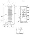
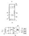
本発明の実施形態1を図1〜図5に基づいて説明する。本実施形態の調光機能付スイッチは、図1〜図3に示すように、縦長の略直方体状のスイッチ本体1と、スイッチ本体1に枢着されるピアノハンドル2と、ピアノハンドル2に着脱自在に取り付けられるワイヤレスリモコン(リモコン本体)3とを主要な構成として有する。
(Embodiment 1)
Embodiment 1 of this invention is demonstrated based on FIGS. As shown in FIGS. 1 to 3, the switch with dimming function of this embodiment is a vertically long, substantially rectangularparallelepiped switch body 1, apiano handle 2 pivotally attached to theswitch body 1, and apiano handle 2. A wireless remote controller (remote controller main body) 3 that can be freely attached is provided as a main configuration.

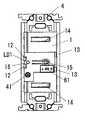
スイッチ本体1の内部には、図4(a)の回路を構成する押釦スイッチSW1、切替スイッチSW2、発光ダイオードLD1、受光素子41などの回路部品を実装したプリント配線板よりなる回路基板(図示せず)と、電源線および負荷線を回路基板に接続するための従来周知の速結端子構造の接続端子(図示せず)とが収納されている。そして、スイッチ本体1の前面には、上下方向における中間部の右側寄りの部位に、周囲にスリットを形成することでスイッチ本体1に片持ち支持され、その自由端で押釦スイッチSW1の押釦(図示せず)を押圧駆動する撓み片15が形成されており、この撓み片15の下側に設けた開口部から切替スイッチSW2の操作子61が露出している。またスイッチ本体1の前面には、上下方向における中央部の左側に発光ダイオードLD1の発光面を外部に臨ませる丸孔16が形成されており、この丸孔16の下側に形成された開口を通して受光素子41の受光面が外部に露出している。またスイッチ本体1の背面には、電源線および負荷線を本体内部の接続端子に接続するための電線挿通孔(図示せず)が開口しており、被覆が剥かれた電線を電線挿通孔に挿入することで、電源線および負荷線を接続端子に容易に接続できるようになっている。  Inside theswitch body 1 is a circuit board (not shown) made of a printed wiring board on which circuit components such as a push button switch SW1, a changeover switch SW2, a light emitting diode LD1, and alight receiving element 41 constituting the circuit of FIG. And a connection terminal (not shown) having a conventionally known fast connection terminal structure for connecting the power supply line and the load line to the circuit board. The front surface of theswitch body 1 is cantilevered by theswitch body 1 by forming a slit around the right side of the middle portion in the vertical direction, and the push button (see FIG. (Not shown) is formed with abending piece 15 that presses and drives, and anoperation element 61 of the changeover switch SW2 is exposed from an opening provided below the bendingpiece 15. In addition, around hole 16 is formed on the front surface of theswitch body 1 on the left side of the central portion in the vertical direction so that the light emitting surface of the light emitting diode LD1 faces the outside, and through an opening formed below theround hole 16. The light receiving surface of thelight receiving element 41 is exposed to the outside. In addition, a wire insertion hole (not shown) for connecting the power supply line and the load line to the connection terminal inside the main body is opened on the back surface of theswitch body 1, and the wire with the sheath removed is used as the wire insertion hole. By inserting, the power supply line and the load line can be easily connected to the connection terminal.

またスイッチ本体1を既製の埋込型配線器具を埋設する場合に用いる取付枠4に着脱自在に取付可能とするために、スイッチ本体1の左側面には上下両側に各一対の取付爪(図示せず)が突設され、右側面には上下方向における中央部に一対の取付爪11が突設されている。右側面に設けた一対の取付爪11の上下両側にはスリット(図示せず)が形成され、一対の取付爪11が突設された部位を内側へ弾性的に撓むようにしてある。  In addition, in order to allow theswitch body 1 to be detachably attached to the mountingframe 4 used when embedding a ready-made embedded wiring device, a pair of mounting claws (see FIG. (Not shown) and a pair of mountingclaws 11 are provided on the right side surface at the center in the vertical direction. Slits (not shown) are formed on both the upper and lower sides of the pair of mountingclaws 11 provided on the right side surface, and the portions where the pair of mountingclaws 11 project are elastically bent inward.

而して、取付枠4にスイッチ本体1を取り付ける際には、スイッチ本体1の左側面に形成された取付爪を、取付枠4の左側片に形成された器具取付孔4aに斜め後方から係止させた後、スイッチ本体1の右側部を前方に押し込むと、スイッチ本体1の右側面に形成された取付爪11が取付枠4の右側片で押されて内側に撓み、この取付爪11が右側片に形成された器具取付孔4aと係止することで、スイッチ本体1が取付枠4に取着されるようになっている。一方、スイッチ本体1を取付枠4から取り外す際には、右側の取付爪11を内側に後退させることで、取付爪11と器具取付孔4aとの係止状態が解除されるので、スイッチ本体1を取付枠4から容易に取り外すことができる。なお、取付枠4の上下の枠片にはボックスねじ7を挿通するための長孔4bが形成されており、長孔4bに通したボックスねじ7を用いて取付枠4を埋込ボックス(図示せず)にねじ固定することができる。また取付枠4の上下の枠片には、プレート枠5を固定するためのプレートねじ用のねじ孔4cが設けられており、プレートねじ(図示せず)を用いて取付枠4の前面にプレート枠5が取着され、さらにプレート枠5の前面に化粧プレート6が重ねて取着されるようになっている。  Thus, when theswitch body 1 is mounted on the mountingframe 4, the mounting claw formed on the left side surface of theswitch body 1 is engaged with the instrument mounting hole 4 a formed on the left side piece of the mountingframe 4 obliquely from behind. After stopping, when the right side portion of theswitch body 1 is pushed forward, the mountingclaw 11 formed on the right side surface of theswitch body 1 is pushed by the right side piece of the mountingframe 4 and bent inward. Theswitch body 1 is attached to the mountingframe 4 by engaging with the instrument mounting hole 4a formed in the right piece. On the other hand, when theswitch body 1 is removed from the mountingframe 4, the locking state between the mountingclaw 11 and the instrument mounting hole 4a is released by retracting theright mounting claw 11 inward. Can be easily removed from the mountingframe 4. Along hole 4b for inserting abox screw 7 is formed in the upper and lower frame pieces of the mountingframe 4, and the mountingframe 4 is embedded in the embedding box (see FIG. 5) using thebox screw 7 passed through thelong hole 4b. (Not shown). The upper and lower frame pieces of the mountingframe 4 are provided withscrew holes 4c for plate screws for fixing theplate frame 5. A plate screw (not shown) is used to attach a plate to the front surface of the mountingframe 4. Theframe 5 is attached, and thedecorative plate 6 is attached to the front surface of theplate frame 5 in an overlapping manner.

またスイッチ本体1の前面には、上下方向における中央部の左端に、横向となった軸部12が間隔を開けて2つ突設してあり、これらの軸部12は上部が横向きの略円柱形状をしている。スイッチ本体1前面の右側には、後述するピアノハンドル2の係止脚片21,21がそれぞれ挿入される係止孔13,13が形成されている。またスイッチ本体1の前面には上下両側部に横長の透孔がそれぞれ形成され、これらの透孔内に一端部がスイッチ本体1に片持ち支持された矩形板状の弾性ばね片14,14がスイッチ本体1と連続一体に形成されており、各弾性ばね片14,14の自由端側は前方に突出して、ピアノハンドル2の裏面の上下にそれぞれ当接し、ピアノハンドル2の右側部を前方に押圧している。  Further, on the front surface of theswitch body 1, two laterally extendingshaft portions 12 project from the left end of the central portion in the vertical direction with a gap therebetween, and theseshaft portions 12 are substantially cylindrical with the upper portion facing horizontally. It has a shape. On the right side of the front surface of theswitch body 1 are formed lockingholes 13 and 13 into which lockingleg pieces 21 and 21 of apiano handle 2 described later are respectively inserted. The front surface of theswitch body 1 is formed with horizontally long through holes on both the upper and lower sides, and rectangular plate-likeelastic spring pieces 14 and 14 with one end cantilevered by theswitch body 1 in these through holes. It is formed integrally with theswitch body 1, the free end side of eachelastic spring piece 14, 14 protrudes forward, abuts on the upper and lower sides of the back surface of thepiano handle 2, and the right side portion of thepiano handle 2 moves forward. Pressing.

一方、ピアノハンドル2は合成樹脂により前面視の形状が略矩形状に形成されており、上述の化粧プレート6の窓孔6aと略同じ大きさに形成されている。ピアノハンドル2の裏面の左端には一対の軸部12と枢支する枢支部(図示せず)が設けられ、右端にはスイッチ本体1の係止孔13,13に挿入される一対の係止脚片21,21が形成されている。またピアノハンドル2の前面の左端部には、上下方向に沿って細幅の突台22が前方に向かって突設されており、突台22以外の部位は突台22よりも薄肉であって、ワイヤレスリモコン3が着脱自在に取り付けられる取付部23を構成している。  On the other hand, thepiano handle 2 is formed of a synthetic resin so that the shape of the front view is substantially rectangular, and is formed to be approximately the same size as thewindow hole 6a of thedecorative plate 6 described above. A pivot support (not shown) that pivots with a pair ofshafts 12 is provided at the left end of the back surface of thepiano handle 2, and a pair of latches inserted into the latch holes 13 and 13 of theswitch body 1 at the right end.Leg pieces 21 and 21 are formed. Further, at the left end portion of the front surface of thepiano handle 2, anarrow protrusion 22 is projected forward along the vertical direction, and the portions other than theprotrusion 22 are thinner than theprotrusion 22. The wirelessremote controller 3 constitutes anattachment part 23 to which the wirelessremote controller 3 is detachably attached.

ピアノハンドル2の突台22の前面側には受光カバー24が取着されている。受光カバー24は、赤外光に対して透光性を有するとともに可視光に対して遮光性を有するような合成樹脂により帯板状に形成されており、かしめなどの方法でピアノハンドル2に固定される。なおピアノハンドル2には、発光ダイオードLD1の発光面及び受光素子41の受光部に対向する部位に透孔(図示せず)が形成されている。発光ダイオードLD1の発光面に対向させて形成した透孔には発光ダイオードLD1の発光を外部に導くプリズムのような導光部材25が取着されおり、この導光部材25は受光カバー24に設けた切欠を通して受光カバー24の前面に露出している。また受光素子41の受光部に対向させて形成した透孔は受光カバー24によって塞がれており、この透孔に臨む受光カバー24の部位にはワイヤレスリモコン3から送信される光信号を受光素子41の受光部に集光させるレンズ部(図示せず)が形成されている。  Alight receiving cover 24 is attached to the front side of the projectingbase 22 of thepiano handle 2. Thelight receiving cover 24 is formed in a band plate shape with a synthetic resin that is transparent to infrared light and has a light shielding property to visible light, and is fixed to thepiano handle 2 by a method such as caulking. Is done. The piano handle 2 is formed with a through hole (not shown) at a portion facing the light emitting surface of the light emitting diode LD1 and the light receiving portion of thelight receiving element 41. Alight guide member 25 such as a prism for guiding the light emitted from the light emitting diode LD1 to the outside is attached to the through hole formed to face the light emitting surface of the light emitting diode LD1. Thelight guide member 25 is provided on thelight receiving cover 24. It is exposed to the front surface of thelight receiving cover 24 through the notch. Further, a through hole formed to face the light receiving portion of thelight receiving element 41 is closed by thelight receiving cover 24, and an optical signal transmitted from the wirelessremote controller 3 is transmitted to the portion of thelight receiving cover 24 facing the through hole. A lens portion (not shown) for condensing light on thelight receiving portion 41 is formed.

そして、ピアノハンドル2は枢支部をスイッチ本体1の軸部12,12に軸支させるとともに、係止脚片21,21をスイッチ本体1の係止孔13,13に挿入することによって、スイッチ本体1に対して回動自在に軸支され、弾性ばね片14などによって操作方向と反対側に付勢されて、復帰位置まで移動する。この時、係止脚片21の先端の爪が係止孔13の孔縁と係止することで、ピアノハンドル2の抜け止めが為される。また発光ダイオードLD1の発光部に導光部材25が対向するとともに、受光素子41の受光面に受光カバー24のレンズ部が対向しており、発光ダイオードLD1の発光が導光部材25を通して外部に導かれ、ワイヤレスリモコン3から送信された光信号が受光カバー24のレンズ部により受光素子41に集光されるのである。この状態からピアノハンドル2の操作側を押操作すると、ピアノハンドル2が軸部12を中心に回転し、ピアノハンドル2の裏面の押圧突起(図示せず)によって撓み片15が内側に押圧され、撓み片15によってスイッチ本体1内部の押釦スイッチSW1の押釦(図示せず)が押操作される。その後ピアノハンドル2の操作側を押す力が無くなると、押釦スイッチSW1の押釦に発生する復帰力や弾性ばね片14に発生する復帰力などを受けてピアノハンドル2が復帰位置まで移動する。すなわち、押釦スイッチSW1の押釦はピアノハンドル2を押操作する間だけ押動される。なお、ピアノハンドル2前面の右端部には、操作位置を表示するための突起26が突設されており、突起26に触れることで暗闇でも操作位置が容易に判別でき、また視覚障害者や高齢者なども操作位置を容易に判別できるようにしている。  The piano handle 2 is pivotally supported by theshaft portions 12 and 12 of theswitch body 1 and the lockingleg pieces 21 and 21 are inserted into the locking holes 13 and 13 of theswitch body 1, thereby 1 is pivotally supported with respect to 1 and is urged to the opposite side to the operation direction by anelastic spring piece 14 and moved to a return position. At this time, the claw at the tip of the lockingleg piece 21 is locked with the hole edge of the lockinghole 13 to prevent the piano handle 2 from coming off. Thelight guide member 25 faces the light emitting portion of the light emitting diode LD1, and the lens portion of thelight receiving cover 24 faces the light receiving surface of thelight receiving element 41. Light emitted from the light emitting diode LD1 is guided to the outside through thelight guide member 25. The optical signal transmitted from the wirelessremote controller 3 is condensed on thelight receiving element 41 by the lens portion of thelight receiving cover 24. When the operation side of thepiano handle 2 is pushed from this state, thepiano handle 2 rotates around theshaft portion 12, and thebending piece 15 is pressed inward by a pressing protrusion (not shown) on the back surface of thepiano handle 2, A push button (not shown) of the pushbutton switch SW 1 inside theswitch body 1 is pushed by the bendingpiece 15. After that, when the force to push the operation side of thepiano handle 2 is lost, thepiano handle 2 moves to the return position in response to the return force generated in the push button of the push button switch SW1, the return force generated in theelastic spring piece 14, and the like. That is, the push button of the push button switch SW1 is pushed only while thepiano handle 2 is pushed. Note that aprojection 26 for displaying the operation position is provided at the right end of the front surface of thepiano handle 2 so that the operation position can be easily identified even in the dark by touching theprojection 26. An operator can easily determine the operation position.

次にワイヤレスリモコン3の構造について説明する。ワイヤレスリモコン3のケース30は合成樹脂により背面および下面が開口した扁平な直方体状に形成されており、ケース30の前面は幅方向における中間部が両側部よりも前方に突出するような曲面に形成されている。そして、ケース30の左右および上下の寸法はピアノハンドル2の取付部23の左右および上下の寸法と略等しい寸法に設定され、ケース30の厚み寸法はケース30を取付部23に取り付けた際にケース30の前面と受光カバー24の前面とが略面一になるような寸法に設定されている。このケース30の内部には図4(b)の回路を形成した回路基板(図示せず)と、電池B1とが収納されている。そして、ケース30の背面には、合成樹脂により板状に形成された可撓性を有するメンブレンシート31が貼り付けられ、このメンブレンシート31によって背面の開口が閉塞される。メンブレンシート31の表面にはドーム状に突出する複数個(例えば5個)の操作凸部32a〜32eが上下に並べて形成されており、各操作凸部32a〜32eには操作内容を示す文字や記号が蓄光材料で印刷されている。これらの操作凸部32a〜32eは後述するスイッチSW11〜SW15の操作部を構成し、操作凸部32a〜32eを押圧するとスイッチSW11〜SW15がオンになる。またケース30の上側面に設けた開口33に臨んで発光ダイオードLD2の発光面が配置されるとともに、ケース30の左側面に設けた開口(図示せず)内に臨んで切替スイッチSW16の操作子(図示せず)が配置されている。またケース30の下面の開口からは、ボタン形の電池B1を保持した電池ホルダが挿入されるようになっており、この電池ホルダによって下面の開口が閉塞されている。  Next, the structure of the wirelessremote controller 3 will be described. Thecase 30 of the wirelessremote control 3 is formed in a flat rectangular parallelepiped shape whose back and bottom surfaces are opened by synthetic resin, and the front surface of thecase 30 is formed in a curved surface such that an intermediate portion in the width direction protrudes forward from both sides. Has been. The left and right and top and bottom dimensions of thecase 30 are set to be substantially equal to the left and right and top and bottom dimensions of the mountingportion 23 of thepiano handle 2, and the thickness dimension of thecase 30 is the same as that when thecase 30 is attached to the mountingportion 23. The dimensions are set such that the front surface of 30 and the front surface of thelight receiving cover 24 are substantially flush with each other. Inside thecase 30 is housed a circuit board (not shown) on which the circuit of FIG. 4B is formed and the battery B1. Aflexible membrane sheet 31 formed in a plate shape with a synthetic resin is attached to the back surface of thecase 30, and the opening on the back surface is closed by themembrane sheet 31. On the surface of themembrane sheet 31, a plurality of (for example, five)operation projections 32 a to 32 e protruding in a dome shape are formed side by side, and eachoperation projection 32 a to 32 e includes characters indicating operation contents, The symbol is printed with phosphorescent material. These operationconvex portions 32a to 32e constitute an operation portion of switches SW11 to SW15 described later, and when the operationconvex portions 32a to 32e are pressed, the switches SW11 to SW15 are turned on. Further, the light emitting surface of the light emitting diode LD2 is disposed facing theopening 33 provided on the upper side surface of thecase 30, and the operator of the changeover switch SW16 is disposed facing the opening (not shown) provided on the left side surface of thecase 30. (Not shown) is arranged. A battery holder holding a button-shaped battery B1 is inserted through the opening on the lower surface of thecase 30, and the opening on the lower surface is closed by the battery holder.

このワイヤレスリモコン3のケース30はピアノハンドル2の取付部23に取り付けられる。すなわちワイヤレスリモコン3をピアノハンドル2の向きに合わせて、ワイヤレスリモコン3を取付部23に前面側から取り付けると、ワイヤレスリモコン3のケース30内部に納装された鉄片(図示せず)がピアノハンドル2の背面に取着された永久磁石(図示せず)によって吸着され、ワイヤレスリモコン3がピアノハンドル2に保持される。この時、ケース30の左側面の上下に設けた係止凹部34が、受光カバー24の上下に設けた係止突起27に係止するとともに、ケース30の背面に設けた係止溝35がピアノハンドル2の突起26と係止することで、ケース30が取付部23に位置決めされ、ケース30の位置ずれが起こりにくくなっている。そして、この状態でワイヤレスリモコン3の前面の右側を押圧すると、ワイヤレスリモコン3の押力をピアノハンドル2が受けて、軸部12を中心に回転し、ピアノハンドル2によって押釦スイッチSW1の押釦が押操作される。その後ワイヤレスリモコン3の操作側を押す力が無くなると、押釦スイッチSW1の押釦に発生する復帰力や弾性ばね片14に発生する復帰力などを受けてピアノハンドル2が復帰位置まで移動する。なお、ワイヤレスリモコン3の前面の右端部にも操作位置を表示するための突起36が突設されている。  Thecase 30 of the wirelessremote controller 3 is attached to theattachment portion 23 of thepiano handle 2. That is, when the wirelessremote controller 3 is aligned with the direction of thepiano handle 2 and the wirelessremote controller 3 is attached to the mountingportion 23 from the front side, an iron piece (not shown) housed in thecase 30 of the wirelessremote controller 3 is attached to thepiano handle 2. The wirelessremote controller 3 is held by thepiano handle 2 by being attracted by a permanent magnet (not shown) attached to the back surface of the piano. At this time, the locking recesses 34 provided at the top and bottom of the left side surface of thecase 30 are locked to the lockingprotrusions 27 provided at the top and bottom of thelight receiving cover 24, and the lockinggroove 35 provided at the back of thecase 30 is piano. By engaging with theprotrusion 26 of thehandle 2, thecase 30 is positioned on the mountingportion 23, and thecase 30 is less likely to be displaced. In this state, when the right side of the front surface of the wirelessremote controller 3 is pressed, thepiano handle 2 receives the pressing force of the wirelessremote controller 3 and rotates around theshaft portion 12, and the push button of the pushbutton switch SW 1 is pressed by thepiano handle 2. Operated. Thereafter, when the force to push the operating side of the wirelessremote controller 3 disappears, thepiano handle 2 moves to the return position in response to the return force generated on the push button of the push button switch SW1 or the return force generated on theelastic spring piece 14. Aprotrusion 36 for displaying the operation position is also provided on the right end of the front surface of the wirelessremote controller 3.

一方、ワイヤレスリモコン3をピアノハンドル2から外してリモコン操作を行う場合は、ワイヤレスリモコン3のケース30の右側面に突設された突条37に手を掛けて、ケース30を前方に引っ張ると、ケース30を容易に取り外すことができ、ケース30を持ち運んでリモコン操作が行えるのである。  On the other hand, when the wirelessremote control 3 is removed from thepiano handle 2 and the remote control operation is performed, a hand is placed on theprotrusion 37 protruding from the right side surface of thecase 30 of the wirelessremote control 3 and thecase 30 is pulled forward. Thecase 30 can be easily removed, and thecase 30 can be carried and remote control operation can be performed.

次に本実施形態の回路構成を図4に基づいて説明する。スイッチ本体1は図4(a)に示すような回路を有し、白熱灯のようなランプLを介して商用電源ACに接続される接続端子T1,T2と、接続端子T1,T2間に接続されてランプLへの電源供給をオン/オフするトライアックのようなスイッチ素子Q1と、例えばフォトダイオードからなり赤外線のような光信号からなるワイヤレス信号を受信する受光素子41(信号受信部)と、モーメンタリ形の押釦スイッチSW1と、マイクロコンピュータからなり、受光素子41の受信信号あるいは押釦スイッチSW1の操作信号に基づいてランプLの点灯出力を制御する制御信号aを出力する制御回路部40と、制御信号aに応じてスイッチ素子Q1の導通角を制御することで、ランプLの点灯出力を変化させる駆動回路42と、接続端子T1,T2間に入力端子間が接続されて商用電源ACの電源電圧を整流する整流回路43と、整流回路43の整流出力を平滑して制御回路部40などの動作電源を生成する電源回路部44とを備えている。尚、図中のLD1はランプLの消灯時に点灯して位置表示を行ったり、点滅周期を変化させることで動作状態を表示するための発光ダイオードであり、SW2はチャンネル切替のための切替スイッチである。  Next, the circuit configuration of the present embodiment will be described with reference to FIG. Theswitch body 1 has a circuit as shown in FIG. 4A and is connected between the connection terminals T1 and T2 connected to the commercial power supply AC via the lamp L such as an incandescent lamp and the connection terminals T1 and T2. A switch element Q1 such as a triac that turns on / off the power supply to the lamp L, and a light receiving element 41 (signal receiving unit) that receives a wireless signal including an optical signal such as an infrared ray, for example. A momentary type push button switch SW1, acontrol circuit unit 40, which comprises a microcomputer, outputs a control signal a for controlling the lighting output of the lamp L based on a reception signal of thelight receiving element 41 or an operation signal of the push button switch SW1, and a controlA drive circuit 42 that changes the lighting output of the lamp L by controlling the conduction angle of the switch element Q1 according to the signal a, and the connection terminal T1A rectifier circuit 43 that rectifies the power supply voltage of the commercial power supply AC with the input terminals connected between T2, and a powersupply circuit section 44 that smoothes the rectified output of therectifier circuit 43 and generates an operating power supply such as thecontrol circuit section 40; It has. In the figure, LD1 is a light-emitting diode that lights up when the lamp L is extinguished to display the position, or displays the operating state by changing the blinking cycle. SW2 is a changeover switch for switching channels. is there.

ワイヤレスリモコン3は図4(b)に示すような回路を有しており、後述のスイッチSW11〜SW15および切替スイッチSW16の操作入力を監視する入力部51と、赤外線のような光信号からなるワイヤレス信号を送信する発光ダイオードLD2と、マイクロコンピュータからなり入力部51を介して入力される操作入力に基づいて発光ダイオードLD2の駆動信号を発生する制御回路部50と、制御回路部50などの動作電源を供給する電池B1と、電池B1の両端間に抵抗R1を介して直列接続された発光ダイオードLD2およびスイッチ素子Q2を具備し、駆動信号に応じてスイッチ素子Q2をオン/オフし、発光ダイオードLD2への通電を制御することでワイヤレス信号を送信させる信号送信部52とを備える。ここで、スイッチSW11は、操作に応じてランプLのオン/オフを反転させる操作信号を出力する。また、スイッチSW12は操作に応じて調光レベルを明るくさせる操作信号を出力し、スイッチSW13は操作に応じて調光レベルを暗くさせる操作信号を出力する。スイッチSW14は、操作に応じて調光レベルを登録又は再生させる操作信号を出力し、スイッチSW15は、操作に応じてタイマ動作を行わせるための操作信号を出力する。  The wirelessremote controller 3 has a circuit as shown in FIG. 4B. The wirelessremote controller 3 includes aninput unit 51 that monitors operation inputs of switches SW11 to SW15 and a changeover switch SW16, which will be described later, and a wireless signal composed of an optical signal such as infrared rays. A light emitting diode LD2 that transmits a signal, acontrol circuit unit 50 that includes a microcomputer and generates a drive signal for the light emitting diode LD2 based on an operation input that is input via theinput unit 51, and an operation power source such as thecontrol circuit unit 50 Battery B1, and light emitting diode LD2 and switch element Q2 connected in series via a resistor R1 between both ends of battery B1, and switch element Q2 is turned on / off according to the drive signal, and light emitting diode LD2 And asignal transmission unit 52 that transmits a wireless signal by controlling energization of the device. Here, the switch SW11 outputs an operation signal for inverting the on / off of the lamp L in accordance with the operation. The switch SW12 outputs an operation signal for increasing the dimming level according to the operation, and the switch SW13 outputs an operation signal for decreasing the dimming level according to the operation. The switch SW14 outputs an operation signal for registering or reproducing the dimming level according to the operation, and the switch SW15 outputs an operation signal for performing a timer operation according to the operation.

本実施形態の調光機能付スイッチの動作について以下に説明する。  The operation of the switch with dimming function of this embodiment will be described below.

先ずスイッチ本体1側でランプLのオン/オフを制御する操作について説明する。ワイヤレスリモコン3の取付時にワイヤレスリモコン3のケース30の操作側を押操作するか、又は、ワイヤレスリモコン3の取外し時にピアノハンドル2の操作側を押操作すると、押圧力を受けてピアノハンドル2が軸部12を中心に回転し、ピアノハンドル2が撓み片15を介して押釦スイッチSW1の押釦を押操作する。制御回路部40は押釦スイッチSW1の操作入力および受光素子41からの信号入力を常時監視しており、押釦スイッチSW1が押操作されると、ランプLのオン/オフを反転させる制御信号aを駆動回路42に出力する。そして、駆動回路42が制御信号aに基づいてスイッチ素子Q1のオン/オフを制御することで、ランプLのオン/オフを反転させ、ランプLを全点灯または消灯させる。このように、スイッチ本体1側でピアノハンドル2、或いは、ピアノハンドル2に装着されたワイヤレススイッチ3のケース30を押操作すると、この押操作に応じてランプLのオン/オフが反転し、点灯時に押操作されるとランプLを消灯させ、消灯時に押操作されるとランプLを全点灯させる。  First, an operation for controlling on / off of the lamp L on theswitch body 1 side will be described. When the operation side of thecase 30 of the wirelessremote control 3 is pushed when the wirelessremote control 3 is attached, or when the operation side of thepiano handle 2 is pushed when the wirelessremote control 3 is detached, thepiano handle 2 receives the pressing force and the shaft The piano handle 2 rotates about theportion 12 and pushes the push button of the push button switch SW1 through theflexure piece 15. Thecontrol circuit unit 40 constantly monitors the operation input of the push button switch SW1 and the signal input from thelight receiving element 41. When the push button switch SW1 is pressed, thecontrol circuit unit 40 drives the control signal a that reverses the on / off state of the lamp L. It outputs to thecircuit 42. Then, the drivingcircuit 42 controls the on / off of the switch element Q1 based on the control signal a, so that the on / off of the lamp L is reversed and the lamp L is fully turned on or off. As described above, when theswitch body 1 side is pressed to operate thepiano handle 2 or thecase 30 of thewireless switch 3 attached to thepiano handle 2, the lamp L is turned on and off in response to the pressing operation, and is lit. When the button L is pressed, the lamp L is turned off. When the button L is pressed when the lamp is turned off, the lamp L is turned on.

次に就寝前やテレビ鑑賞時にワイヤレスリモコン3をピアノハンドル2から取り外し、ワイヤレスリモコン3を用いてリモコン操作を行う場合の動作について説明する。ワイヤレスリモコン3では、操作凸部32a〜32eが押操作されると、対応するスイッチSW11〜SW15の操作信号が入力部51を介して制御回路部50に入力される。制御回路部50は、入力部51を介して操作信号が与えられると、この操作信号に基づいて所定のワイヤレス信号を送信させるための制御信号を発生する。そして、信号送信部52が制御回路部40の制御信号に応じて発光ダイオードLD2を駆動し、赤外線のような光信号からなるワイヤレス信号でランプLの制御信号を送信する。このワイヤレス信号のフォーマットは例えば家電製品協会の自主規格に準拠したフォーマットを使用している。  Next, the operation when the wirelessremote controller 3 is detached from thepiano handle 2 and the remote controller is operated using the wirelessremote controller 3 before going to bed or when watching TV will be described. In the wirelessremote controller 3, when the operationconvex portions 32 a to 32 e are pressed, the operation signals of the correspondingswitches SW 11 toSW 15 are input to thecontrol circuit unit 50 via theinput unit 51. When an operation signal is given through theinput unit 51, thecontrol circuit unit 50 generates a control signal for transmitting a predetermined wireless signal based on the operation signal. And thesignal transmission part 52 drives light emitting diode LD2 according to the control signal of thecontrol circuit part 40, and transmits the control signal of the lamp | ramp L with the wireless signal which consists of optical signals like infrared rays. As the format of this wireless signal, for example, a format conforming to a voluntary standard of the home appliance association is used.

ここに、オン/オフ操作釦を構成する操作凸部32aが押操作(スイッチSW11がオン)された場合はランプLのオン/オフを反転させる制御信号(オン/オフ信号)が送信される。また調光操作釦を構成する操作凸部32b,32cの内、操作凸部32bが押操作(スイッチSW12がオン)された場合はランプLの調光レベルを明るくする制御信号(明調光信号)が送信され、操作凸部32cが押操作(スイッチSW13がオン)された場合はランプLの調光レベルを暗くする制御信号(暗調光信号)が送信される。さらに、調光レベル録再釦を構成する操作凸部32dが押操作(スイッチSW14がオン)された場合は調光レベルを登録/再生させる制御信号(レベル録再信号)が送信される。また更に、操作凸部32eが押操作(スイッチSW15がオン)された場合はタイマ動作を行わせる制御信号(タイマ制御信号)が送信される。  Here, when the operationconvex portion 32a constituting the on / off operation button is pushed (switch SW11 is turned on), a control signal (on / off signal) for inverting the on / off of the lamp L is transmitted. A control signal (bright dimming signal) that brightens the dimming level of the lamp L when the operationconvex portion 32b of the operationconvex portions 32b and 32c constituting the dimming operation button is pressed (switch SW12 is turned on). ) Is transmitted, and a control signal (dark dimming signal) for dimming the dimming level of the lamp L is transmitted when the operationconvex portion 32c is pushed (the switch SW13 is turned on). Further, when the operationconvex portion 32d constituting the dimming level recording / reproducing button is pressed (switch SW14 is turned on), a control signal (level recording / reproducing signal) for registering / reproducing the dimming level is transmitted. Furthermore, when the operationconvex portion 32e is pushed (the switch SW15 is turned on), a control signal (timer control signal) for performing a timer operation is transmitted.

一方、スイッチ本体1では、制御回路部40が押釦スイッチSW1の操作入力および受光素子41からの信号入力を常時監視しており、受光素子41が制御信号を受信すると、受信した制御信号に基づいて駆動回路42の動作を制御し、ランプLの点灯出力を制御する。  On the other hand, in theswitch body 1, thecontrol circuit unit 40 constantly monitors the operation input of the pushbutton switch SW1 and the signal input from thelight receiving element 41. When thelight receiving element 41 receives the control signal, thecontrol circuit unit 40 receives the control signal. The operation of thedrive circuit 42 is controlled, and the lighting output of the lamp L is controlled.

ここで、受光素子41が調光レベルを増加或いは減少させる調光信号を受信した場合、制御回路部40は、調光信号が入力される間中、スイッチ素子Q2の導通角を増加或いは減少させて、ランプLの調光レベルを明るくする方向或いは暗くする方向に変化させており、その後調光信号の入力が停止すると、現在の調光レベルを制御回路部40に内蔵されたフラッシュメモリ(図示せず)に記憶させる。また受光素子41がオン/オフ信号を受信した場合、制御回路部40は、消灯中であればフラッシュメモリに記憶された調光レベルでランプLを調光点灯させ、点灯中であればランプLを消灯させており、調光レベルでの点灯と消灯を交互に繰り返させる。さらに受光素子41がレベル録再信号を一定時間(例えば2秒)以上連続して受信すると、制御回路部40は、現在の調光レベルを内蔵のフラッシュメモリ(記憶手段)に登録させる。その後受光素子41がレベル録再信号を上記一定時間よりも短い時間だけ受信すると、制御回路部40は、フラッシュメモリに登録された調光レベルでランプLを調光点灯させる。また更に、受光素子41がタイマ制御信号を受信すると、制御回路部40は、ランプLを点灯させるとともに、所定のタイマ時間(例えば60分)が経過した後にランプLを消灯させる。  When thelight receiving element 41 receives a dimming signal that increases or decreases the dimming level, thecontrol circuit unit 40 increases or decreases the conduction angle of the switch element Q2 while the dimming signal is input. Then, the dimming level of the lamp L is changed in the direction of brightening or dimming, and when the input of the dimming signal is stopped thereafter, the current dimming level is stored in a flash memory (see FIG. (Not shown). When thelight receiving element 41 receives the on / off signal, thecontrol circuit unit 40 causes the lamp L to be dimmed at the dimming level stored in the flash memory if the light is off, and if the light is on, the lamp L Is turned off, and lighting and turning off at the light control level are repeated alternately. Further, when thelight receiving element 41 continuously receives the level recording / reproducing signal for a predetermined time (for example, 2 seconds) or longer, thecontrol circuit unit 40 registers the current dimming level in the built-in flash memory (storage means). Thereafter, when thelight receiving element 41 receives the level recording / reproducing signal for a time shorter than the predetermined time, thecontrol circuit unit 40 causes the lamp L to be dimmed and lit at the dimming level registered in the flash memory. Further, when thelight receiving element 41 receives the timer control signal, thecontrol circuit unit 40 turns on the lamp L and turns off the lamp L after a predetermined timer time (for example, 60 minutes) elapses.

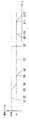
次に本実施形態の動作を図5に基づいて具体的に説明する。初期状態において消灯中の時刻t1にワイヤレスリモコン3の操作凸部32aが押操作されて、ワイヤレスリモコン3からスイッチ本体1にオン/オフ信号が送信されると、スイッチ本体1の制御回路部40は内蔵するフラッシュメモリに記憶された前回調整時の調光レベルでランプLを調光点灯させる。なお初期状態では調光レベルの初期値が100%となっているので、制御回路部40はランプLを全点灯状態で点灯させる。その後、時刻t3においてワイヤレスリモコン3の操作凸部32cが押操作され、ワイヤレスリモコン3からスイッチ本体1に暗調光信号が送信されると、スイッチ本体1の制御回路部40はランプLの調光レベルを100%(全点灯状態)から徐々に低下させる。そして、時刻t4において操作凸部32cが離され、ワイヤレスリモコン3から暗調光信号が送信されなくなると、制御回路部40は調光レベルの変化を停止し、現在の調光レベルでランプLを調光点灯させるとともに、現在の調光レベルを内蔵するフラッシュメモリに記憶させる。その後、時刻t5において、操作凸部32aが再び押操作されると、ワイヤレスリモコン3からスイッチ本体1にオン/オフ信号が送信され、スイッチ本体1の制御回路部40はランプLを調光点灯状態から消灯状態に切り替える。  Next, the operation of the present embodiment will be specifically described with reference to FIG. When the operationconvex portion 32a of the wirelessremote controller 3 is pushed at the time t1 when the light is off in the initial state and an on / off signal is transmitted from the wirelessremote controller 3 to theswitch body 1, thecontrol circuit section 40 of theswitch body 1 The lamp L is dimmed at the dimming level at the previous adjustment stored in the built-in flash memory. Since the initial value of the dimming level is 100% in the initial state, thecontrol circuit unit 40 turns on the lamp L in the fully lit state. After that, when the operationconvex portion 32c of the wirelessremote controller 3 is pressed at time t3 and a dark dimming signal is transmitted from the wirelessremote controller 3 to the switchmain body 1, thecontrol circuit unit 40 of the switchmain body 1 adjusts the dimming of the lamp L. The level is gradually reduced from 100% (all lighting state). When the operationconvex portion 32c is released at time t4 and the dark dimming signal is not transmitted from the wirelessremote controller 3, thecontrol circuit unit 40 stops changing the dimming level, and the lamp L is turned on at the current dimming level. The dimming is turned on and the current dimming level is stored in a built-in flash memory. After that, when the operationconvex portion 32a is pushed again at time t5, an on / off signal is transmitted from the wirelessremote controller 3 to theswitch body 1, and thecontrol circuit section 40 of theswitch body 1 turns the lamp L into a dimmed lighting state. Switch from to off.

そして、消灯中の時刻t7において、スイッチ本体1のピアノハンドル2が押操作されて、押釦スイッチSW1がオンになると、制御回路部40は押釦スイッチSW1からの操作入力に基づいてランプLを全点灯させる。また時刻t8においてピアノハンドル2が再び押操作されて、押釦スイッチSW1がオンになると、制御回路部40は押釦スイッチSW1からの操作入力に基づいてランプLを消灯させる。  When the piano handle 2 of theswitch body 1 is pushed and the push button switch SW1 is turned on at time t7 when the light is off, thecontrol circuit unit 40 turns on the lamp L completely based on the operation input from the push button switch SW1. Let When thepiano handle 2 is pushed again at time t8 and the push button switch SW1 is turned on, thecontrol circuit unit 40 turns off the lamp L based on the operation input from the push button switch SW1.

次に、消灯中の時刻t9において、ワイヤレスリモコン3の操作凸部32aが押操作されて、ワイヤレスリモコン3からスイッチ本体1にオン/オフ信号が送信されると、制御回路部40はオン/オフ信号に応じてフラッシュメモリに記憶された前回調整時の調光レベルA1でランプLを点灯させる。また、調光点灯中の時刻t11において、操作凸部32aが再び押操作されると、ワイヤレスリモコン3からスイッチ本体1にオン/オフ信号が再び送信され、制御回路部40はオン/オフ信号に応じてランプLを調光点灯状態から消灯状態に切り替える。  Next, when the operationconvex portion 32a of the wirelessremote controller 3 is pushed and an on / off signal is transmitted from the wirelessremote controller 3 to theswitch body 1 at time t9 when the light is off, thecontrol circuit section 40 is turned on / off. In response to the signal, the lamp L is turned on at the dimming level A1 at the previous adjustment stored in the flash memory. Further, when the operationconvex portion 32a is pushed again at time t11 when the dimming is on, an on / off signal is transmitted again from the wirelessremote controller 3 to theswitch body 1, and thecontrol circuit unit 40 changes to the on / off signal. Accordingly, the lamp L is switched from the dimming lighting state to the extinguishing state.

このように、本実施形態ではワイヤレスリモコン3の調光操作釦(操作凸部32b,32c)を押操作することで、スイッチ本体1と離れた場所からランプLの調光レベルを変化させることが可能になり、就寝時やテレビ鑑賞時においてスイッチ本体1の設置場所まで行かなくても手元で調光操作を行えるから、使い勝手が向上する。  Thus, in this embodiment, the light control level of the lamp L can be changed from a place away from theswitch body 1 by pressing the light control buttons (operationconvex portions 32b and 32c) of the wirelessremote controller 3. This makes it possible to perform the dimming operation at hand without going to the place where theswitch body 1 is installed at the time of going to bed or watching TV.

またスイッチ本体1のピアノハンドル2を押操作した場合は、制御回路部40がランプLを全点灯又は消灯させるが、ワイヤレスリモコン3の操作凸部32aを押操作した場合は、制御回路部40が、ランプLを前回調整された調光レベルで調光点灯させるか又は消灯させている。ここで、部屋に入室したり退室する際にはランプLを全点灯又は消灯させる場合が多く、一般に壁に固定されたスイッチ本体1のピアノハンドル2を操作する場合が多いので、ピアノハンドル2の操作に応じてランプLを全点灯又は消灯させるのが好ましい。また例えば就寝前にランプLを減光させた状態で、ランプLを消灯させて就寝した後、深夜にトイレなどで起きた場合、ランプLを全点灯させると目が眩んでしまうが、ワイヤレスリモコン3の操作凸部32aを押操作してランプLを点灯させると、制御回路部40は前回調整された調光レベルでランプLを調光点灯させるので、使用者が眩しく感じるのを防止でき、使い勝手が更に向上する。  When the piano handle 2 of theswitch body 1 is pressed, thecontrol circuit unit 40 turns on or off the lamp L. However, when the operationconvex portion 32a of the wirelessremote controller 3 is pressed, thecontrol circuit unit 40 The lamp L is dimmed or turned off at the previously adjusted dimming level. Here, when entering or leaving the room, the lamp L is often turned on or off, and generally the piano handle 2 of theswitch body 1 fixed to the wall is often operated. It is preferable to turn on or off the lamp L in accordance with the operation. Also, for example, if the lamp L is dimmed before going to bed and the lamp L is extinguished and then goes to bed and then wakes up in the bathroom at night, turning on the lamp L all the time makes the eyes dazzling. When the lamp L is lit by pushing the operation convex portion 3a of No. 3, thecontrol circuit unit 40 dims the lamp L at the dimming level adjusted last time, so that the user can be prevented from feeling dazzling, Usability is further improved.

またワイヤレスリモコン3を用いてランプLのオン/オフ操作を行う場面は、テレビなどを鑑賞したり、就寝している場合なので、ワイヤレスリモコン3の操作凸部32aを操作してランプLを調光点灯又は消灯させる場合には、制御回路部40が所定のフェード時間(時刻t1〜t2、時刻t5〜t6、時刻t9〜t10、時刻t11〜t12)内に調光レベルを目標値まで徐々に変化させることで、使用者に違和感を与えたり、目が眩んだりするのを防止できる。さらに造営材に固定されたスイッチ本体1の押釦スイッチSW1をピアノハンドル2を介して押操作する場面は、部屋に入室したり、部屋から退室する場合なので、ランプLの光出力を徐々に変化させる必要はなく、押釦スイッチSW1からの操作信号が入力された場合はランプLの光出力を目標値まで瞬時に変化させることで、ランプLの光出力を短時間に変化させることができる。  The scene where the wirelessremote control 3 is used to turn on / off the lamp L is when watching TV or sleeping, so the operationconvex portion 32a of the wirelessremote control 3 is operated to dimm the lamp L. When turning on or off, thecontrol circuit unit 40 gradually changes the dimming level to the target value within a predetermined fade time (time t1 to t2, time t5 to t6, time t9 to t10, time t11 to t12). This makes it possible to prevent the user from feeling uncomfortable or dazzling the eyes. Further, the scene where the push button switch SW1 of theswitch body 1 fixed to the construction material is pushed through thepiano handle 2 is when entering or leaving the room, so the light output of the lamp L is gradually changed. There is no need, and when the operation signal from the pushbutton switch SW1 is input, the light output of the lamp L can be changed in a short time by instantaneously changing the light output of the lamp L to the target value.

またワイヤレスリモコン3の操作凸部32dを押操作すると、ワイヤレスリモコン3からレベル録再信号がスイッチ本体1に送信されるのであるが、操作凸部32dを長押しして、レベル録再信号が一定時間(例えば2秒間)以上送信されると(つまり受光素子41がレベル録再信号を一定時間以上受信すると)、制御回路部40は現在の調光レベルの設定値をシーン再生用の調光レベルとして内蔵するフラッシュメモリに登録させる。その後、ワイヤレスリモコン3の操作凸部32dが一定時間よりも短い時間だけ押操作されると、ワイヤレスリモコン3からレベル録再信号がスイッチ本体1に短時間送信される。この時、受光素子41では一定時間よりも短い時間だけレベル録再信号を受信するので、このレベル録再信号に応じて制御回路部40がフラッシュメモリからシーン再生用の調光レベルを読み込み、読み込んだ調光レベルでランプLを調光点灯させる。このように、ワイヤレスリモコン3の操作凸部32b,32cを操作してランプLの調光レベルを所望のレベルに調整した後に、操作凸部32dを長押しして現在の調光レベルを記憶させておけば、その後操作凸部32dを短時間押操作するだけで、ランプLを好みの調光レベルで点灯させることが可能になり、使い勝手が向上する。なお本実施形態では現在の調光レベルやシーン再生用の調光レベルを制御回路部40が内蔵するフラッシュメモリに記憶させているが、EEPROMのような不揮発性のメモリに記憶させても良い。  When the operationconvex portion 32d of the wirelessremote controller 3 is pushed, a level recording / reproducing signal is transmitted from the wirelessremote controller 3 to theswitch body 1. However, the level recording / reproducing signal is kept constant by long pressing the operationconvex portion 32d. When a time (for example, 2 seconds) or more is transmitted (that is, when thelight receiving element 41 receives a level recording / reproducing signal for a predetermined time or longer), thecontrol circuit unit 40 sets the current dimming level setting value to the dimming level for scene reproduction. To be registered in the internal flash memory. Thereafter, when the operationconvex portion 32d of the wirelessremote controller 3 is pressed for a time shorter than a predetermined time, a level recording / reproducing signal is transmitted from the wirelessremote controller 3 to theswitch body 1 for a short time. At this time, since thelight receiving element 41 receives the level recording / reproducing signal for a time shorter than a predetermined time, thecontrol circuit unit 40 reads the dimming level for scene reproduction from the flash memory in response to the level recording / reproducing signal. The lamp L is dimmed at the dimming level. As described above, after operating the operationconvex portions 32b and 32c of the wirelessremote controller 3 to adjust the dimming level of the lamp L to a desired level, the operationconvex portion 32d is pressed and held to store the current dimming level. Then, the lamp L can be lit at a desired dimming level by simply pressing the operationconvex portion 32d for a short time, and the usability is improved. In the present embodiment, the current dimming level and scene dimming level are stored in the flash memory built in thecontrol circuit unit 40, but may be stored in a non-volatile memory such as an EEPROM.

またワイヤレスリモコン3のケース30は扁平な直方体状に形成され、長手方向の一端部に信号送信部52の発光ダイオードLD2が配置されており、ケース30の裏面には、発光ダイオードLD2が配置された一端部に近い側から、オン/オフ操作用の操作凸部32a、調光操作用の操作凸部32b,32c、調光レベルの登録/再生用の操作凸部32d、タイマ制御用の操作凸部32eを順番に配置してある。ここで、ケース30を手で把持する際には発光ダイオードLD2が配置された長手方向一端部を前方(身体と反対側)に向けて手で把持するのであるが、長手方向一端部に近い側にオン/オフ操作用の操作凸部32dを配置しているので、利き手が左右何れの場合でも操作頻度の比較的高いオン/オフ操作用の操作凸部32dがケース30を把持する手の親指の位置に近くなり、ケース30を把持する手でオン/オフ操作用の操作凸部32dを操作しやすいという利点がある。尚、本実施形態では長手方向の一端部から、オン/オフ操作用の操作凸部32a、調光操作用の操作凸部32b,32c、調光レベルの登録/再生用の操作凸部32d、タイマ制御用の操作凸部32eを順番に配置してあるが、オン/オフ操作用の操作凸部32aを長手方向の一端部に最も近付けて配置すれば、他の操作凸部32b〜32eの配置は上記以外の順番で配置しても良く、例えば長手方向の一端部から、オン/オフ操作用の操作凸部32a、調光レベルの登録/再生用の操作凸部32d、調光操作用の操作凸部32b,32c、タイマ制御用の操作凸部32eの順番で配置しても良い。  Thecase 30 of the wirelessremote controller 3 is formed in a flat rectangular parallelepiped shape, the light emitting diode LD2 of thesignal transmission unit 52 is disposed at one end in the longitudinal direction, and the light emitting diode LD2 is disposed on the back surface of thecase 30. From the side close to one end, anoperation protrusion 32a for on / off operation,operation protrusions 32b and 32c for dimming operation, anoperation protrusion 32d for registration / reproduction of dimming level, and an operation protrusion for timer control Theparts 32e are arranged in order. Here, when thecase 30 is gripped by hand, one end in the longitudinal direction where the light emitting diode LD2 is disposed is gripped by hand toward the front (opposite to the body), but the side close to the one end in the longitudinal direction. Since the operationconvex portion 32d for on / off operation is arranged on the left and right, the operationconvex portion 32d for on / off operation having a relatively high operation frequency regardless of whether the dominant hand is left or right is the thumb of the hand holding thecase 30. Thus, there is an advantage that the operationconvex portion 32d for on / off operation can be easily operated by a hand holding thecase 30. In this embodiment, from one end portion in the longitudinal direction, an operationconvex portion 32a for on / off operation, operationconvex portions 32b and 32c for dimming operation, an operationconvex portion 32d for dimming level registration / reproduction, Although the operationconvex portions 32e for timer control are arranged in order, if the operationconvex portion 32a for on / off operation is arranged closest to one end portion in the longitudinal direction, the other operationconvex portions 32b to 32e are arranged. Arrangements may be made in an order other than the above. For example, from one end in the longitudinal direction, an operationconvex part 32a for on / off operation, an operationconvex part 32d for dimming level registration / reproduction, and for dimming operation The operation protrusions 32b and 32c and theoperation protrusion 32e for timer control may be arranged in this order.

またワイヤレスリモコン3のケース30には、前面の一部又は略全体に蓄光材料を印刷することで発光表示部38aを形成するとともに、背面の一部に蓄光材料を印刷することで発光表示部38bを形成してあり、これらの発光表示部38a,38bが暗所で発光することで、何れの面を上にして置かれた場合でもワイヤレスリモコン3の位置を容易に見つけることができる。また、ケース30の裏面に設けた操作凸部32a〜32eには、操作内容を示す文字や記号が蓄光材料で印刷されているので、暗所でこれらの文字や記号が発光することにより、操作部位を容易に判別できる。  In addition, thecase 30 of the wirelessremote controller 3 forms a light emittingdisplay portion 38a by printing a phosphorescent material on a part or substantially the whole of the front surface, and light emittingdisplay portion 38b by printing the phosphorescent material on a portion of the rear surface. These light emittingdisplay portions 38a and 38b emit light in the dark, so that the position of the wirelessremote controller 3 can be easily found regardless of which surface is placed. In addition, since characters and symbols indicating the operation contents are printed with a phosphorescent material on theoperation protrusions 32a to 32e provided on the back surface of thecase 30, the characters and symbols emit light in a dark place. The site can be easily identified.

尚、ワイヤレスリモコン3からワイヤレス信号で送信される制御信号には、切替スイッチSW16で切替設定されたチャンネルのデータが含まれており、制御回路部40では、切替スイッチSW2によって設定された自己のチャンネルと、ワイヤレス信号で送信された制御信号に含まれるチャンネルとが一致する場合のみ、ワイヤレスリモコン3からの制御信号を受け付けるようにしている。  The control signal transmitted as a wireless signal from the wirelessremote controller 3 includes data of the channel set by the changeover switch SW16. In thecontrol circuit unit 40, the own channel set by the changeover switch SW2 is included. The control signal from the wirelessremote controller 3 is accepted only when the channel included in the control signal transmitted by the wireless signal matches.

(実施形態2)
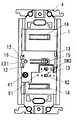
本発明の実施形態2を図6に基づいて説明する。本実施形態では、上述の実施形態1において、ワイヤレスリモコン3のケース30における受光カバー24側の側面に、受光カバー24側へ突出する突起39を設けてある。またスイッチ本体1に、突起39の有無を検知することによって、ワイヤレスリモコン3が装着されているか否かを検知するリモコン装着検知スイッチSW4を設けている。尚、突起39およびリモコン装着検知スイッチSW4以外の構成は実施形態1と同様であるので、共通する構成要素には同一の符号を付して、その説明は省略する。
(Embodiment 2)
A second embodiment of the present invention will be described with reference to FIG. In the present embodiment, in the above-described first embodiment, theprojection 39 protruding toward thelight receiving cover 24 is provided on the side surface of thecase 30 of the wirelessremote controller 3 on thelight receiving cover 24 side. Further, theswitch body 1 is provided with a remote controller mounting detection switch SW4 that detects whether or not the wirelessremote controller 3 is mounted by detecting the presence or absence of theprotrusion 39. Since the configuration other than theprotrusion 39 and the remote controller mounting detection switch SW4 is the same as that of the first embodiment, common components are denoted by the same reference numerals and description thereof is omitted.

リモコン装着検知スイッチSW4はモーメンタリ形のスイッチからなり、ワイヤレスリモコン3がピアノハンドル2に装着されると、ワイヤレスリモコン3の突起39でリモコン装着検知スイッチSW4の操作子(図示せず)が押されて、リモコン装着検知スイッチSW4はオンになる。一方、ワイヤレスリモコン3がピアノハンドル2から外されると、リモコン装着検知スイッチSW4がオフになる。  The remote controller mounting detection switch SW4 is composed of a momentary switch. When the wirelessremote controller 3 is mounted on thepiano handle 2, an operator (not shown) of the remote controller mounting detection switch SW4 is pushed by theprotrusion 39 of the wirelessremote controller 3. The remote controller mounting detection switch SW4 is turned on. On the other hand, when the wirelessremote controller 3 is removed from thepiano handle 2, the remote controller attachment detection switch SW4 is turned off.

制御回路部40では、リモコン装着検知スイッチSW4からのスイッチ入力を常時監視しており、リモコン装着検知スイッチSW4がオンの場合、つまりワイヤレスリモコン3の取付状態を検知している場合は、ピアノハンドル2が押操作されて押釦スイッチSW1から操作信号が入力されると、ランプLの点灯/消灯を反転させて全点灯させるか又は消灯させている。一方、リモコン装着検知スイッチSW4がオフの場合、つまりワイヤレスリモコン3の取り外し状態を検知している場合、制御回路部40は、ピアノハンドル2が押操作されて押釦スイッチSW1から操作信号が入力されると、ランプLの点灯/消灯を反転させて、調光信号で調整された調光レベルで点灯させるか又は消灯させている。  Thecontrol circuit unit 40 constantly monitors the switch input from the remote controller attachment detection switch SW4. When the remote controller attachment detection switch SW4 is on, that is, when the attachment state of the wirelessremote controller 3 is detected, thepiano handle 2 is detected. When an operation signal is input from the push button switch SW1, the lighting / extinguishing of the lamp L is reversed to turn on or turn off the lamp L. On the other hand, when the remote controller attachment detection switch SW4 is off, that is, when the removal state of the wirelessremote controller 3 is detected, thecontrol circuit unit 40 receives an operation signal from the push button switch SW1 when thepiano handle 2 is pressed. The lighting / extinguishing of the lamp L is reversed, and the lighting is turned on or off at the dimming level adjusted by the dimming signal.

ここで、就寝前やテレビ鑑賞の場面ではランプLを調光レベルで点灯又は消灯させ、それ以外の場面ではランプLを全点灯又は消灯させることが望ましいが、本実施形態では就寝前やテレビの鑑賞中ではないと予想される場合、すなわちワイヤレスリモコン3の取付状態を検知している場合、ピアノハンドル2を介して押釦スイッチSW1の押釦を押操作すると、制御回路部40がランプLを全点灯又は消灯させている。一方、就寝前やテレビの鑑賞中と予想される場合、すなわちワイヤレスリモコン3の取り外し状態を検知している場合、ピアノハンドル2を介して押釦スイッチSW1の押釦を押操作すると、制御回路部40はランプLを調光点灯又は消灯させている。このように、ワイヤレスリモコン3が外されているか否かで、オン操作時にランプLを全点灯させるか調光点灯させるかを切り替えているので、使い勝手を向上させることができる。  Here, it is desirable to turn on or off the lamp L at the dimming level before going to bed or watching TV, and to turn on or turn off the lamp L in all other situations. However, in this embodiment, the lamp L is turned on or off. When it is predicted that the wirelessremote control 3 is not installed, that is, when the wirelessremote controller 3 is detected, when the push button of the push button switch SW1 is pressed via thepiano handle 2, thecontrol circuit unit 40 turns on the lamp L completely. Or it is turned off. On the other hand, when it is predicted that the user is expecting to go to bed or watching TV, that is, when the removal state of the wirelessremote controller 3 is detected, when the push button of the push button switch SW1 is pressed through thepiano handle 2, thecontrol circuit unit 40 is The lamp L is dimmed or turned off. In this way, whether or not the lamp L is fully lit or dimmed is switched depending on whether or not the wirelessremote controller 3 is disconnected, so that the usability can be improved.

(実施形態3)
本発明の実施形態3を図7に基づいて説明する。本実施形態では、上述の実施形態1において、ピアノハンドル2を所定時間内(例えば2秒間)に複数回押操作することで、制御回路部40に押釦スイッチSW1の操作信号が所定時間内に複数回入力されると、制御回路部40が、前回調光信号で調整された調光レベルでランプLを調光点灯させている。尚、制御回路部40の制御動作以外は実施形態1と同様であるので、共通する構成要素には同一の符号を付して、その説明は省略する。
(Embodiment 3)
A third embodiment of the present invention will be described with reference to FIG. In the present embodiment, in the above-described first embodiment, thepiano handle 2 is pressed a plurality of times within a predetermined time (for example, 2 seconds), whereby a plurality of operation signals of the push button switch SW1 are transmitted to thecontrol circuit unit 40 within the predetermined time. When the input is repeated, thecontrol circuit unit 40 causes the lamp L to be dimmed at the dimming level adjusted by the previous dimming signal. In addition, since it is the same as that ofEmbodiment 1 except control operation of thecontrol circuit part 40, the same code | symbol is attached | subjected to a common component and the description is abbreviate | omitted.

上述のように制御回路部40は、押釦スイッチSW1からの操作入力を常時監視しており、ピアノハンドル2を1回押操作して、押釦スイッチSW1から操作信号が与えられる毎に、ランプLの点灯/消灯を反転させて、ランプLを全点灯させるか又は消灯させているが、押釦スイッチSW1からの操作信号が所定時間内(例えば2秒間)に複数回入力されると、前回調光信号で調整された調光レベルでランプLを調光点灯させている。  As described above, thecontrol circuit unit 40 constantly monitors the operation input from the push button switch SW1, and each time the operation signal is given from the push button switch SW1 by pressing thepiano handle 2 once, The lighting / extinction is reversed, and the lamp L is fully lit or extinguished. However, if the operation signal from the push button switch SW1 is input a plurality of times within a predetermined time (for example, 2 seconds), the previous dimming signal The lamp L is dimmed at the dimming level adjusted in.

ここで、本実施形態の動作を図7に基づいて説明する。ランプLが全点灯している時刻t31においてピアノハンドル2が押操作されて、押釦スイッチSW1の操作信号が制御回路部40に入力されると、押釦スイッチSW1の操作信号が停止した時刻t32において制御回路部40はランプLを消灯させる。その後、時刻t32から所定時間DTが経過するまでの間にピアノハンドル2が再度押操作されて、押釦スイッチSW1の操作信号が制御回路部40に入力されると(時刻t33)、制御回路部40では所定時間DT内に操作信号が複数回入力されたと判断し、前回調整された調光レベルA1でランプLを調光点灯させる。このように、ピアノハンドル2を所定時間DT内に複数回押操作することで、ワイヤレスリモコン3を用いて前回調整された調光レベルでランプLを調光点灯させることができるので、スイッチ本体1とワイヤレスリモコン3の両方でランプLを調光点灯させることができ、ワイヤレスリモコン3が見当たらない場合でもスイッチ本体1側でランプLを調光点灯させることができる。  Here, the operation of the present embodiment will be described with reference to FIG. When thepiano handle 2 is pressed at time t31 when the lamp L is fully lit and an operation signal of the pushbutton switch SW1 is input to thecontrol circuit unit 40, control is performed at time t32 when the operation signal of the pushbutton switch SW1 is stopped. Thecircuit unit 40 turns off the lamp L. After that, when thepiano handle 2 is pushed again during the predetermined time DT from the time t32 and the operation signal of the push button switch SW1 is input to the control circuit unit 40 (time t33), thecontrol circuit unit 40 Then, it is determined that the operation signal has been input a plurality of times within the predetermined time DT, and the lamp L is dimmed and lit at the previously adjusted dimming level A1. In this way, by pressing the piano handle 2 a plurality of times within the predetermined time DT, the lamp L can be dimmed and lit at the dimming level adjusted last time using the wirelessremote controller 3. And the wirelessremote controller 3 can dimm the lamp L, and even if the wirelessremote controller 3 is not found, the lamp L can be dimmed on theswitch body 1 side.

また、ランプLが調光点灯中の時刻t34において、ピアノハンドル2が押操作されて、押釦スイッチSW1の操作信号が制御回路部40に入力されると、押釦スイッチSW1の操作信号が停止した時刻t35において制御回路部40はランプLを消灯させる。さらに、時刻t35から所定時間DTが経過するまでの間にピアノハンドル2が再度押操作されて、押釦スイッチSW1の操作信号が制御回路部40に入力されると(時刻t36)、制御回路部40では所定時間DT内に操作信号が複数回入力されたと判断し、ランプLを全点灯させる。  Also, at time t34 when the lamp L is dimmed, when thepiano handle 2 is pushed and the operation signal of the pushbutton switch SW1 is input to thecontrol circuit unit 40, the time when the operation signal of the pushbutton switch SW1 stops At t35, thecontrol circuit unit 40 turns off the lamp L. Furthermore, when thepiano handle 2 is pushed again during a predetermined time DT from the time t35 and an operation signal of the push button switch SW1 is input to the control circuit unit 40 (time t36), thecontrol circuit unit 40 Then, it is determined that the operation signal has been input a plurality of times within the predetermined time DT, and the lamp L is fully lit.

(実施形態4)
本発明の実施形態4を図面を参照して説明する。本実施形態では、図8に示すように実施形態1〜3の何れかの調光機能付スイッチにおいて、スイッチ本体1の前面に調光釦17a,17bを設け、スイッチ本体1側でも調光操作を行えるようにしている。なお、調光釦17a,17b以外の構成は実施形態1〜3と同様であるので共通する構成要素には、同一の符号を付してその説明は省略する。
(Embodiment 4)
Embodiment 4 of the present invention will be described with reference to the drawings. In the present embodiment, as shown in FIG. 8, in any switch with a dimming function of the first to third embodiments, dimmingbuttons 17 a and 17 b are provided on the front surface of theswitch body 1, and the dimming operation is also performed on theswitch body 1 side. Can be done. Since the configuration other than the dimmingbuttons 17a and 17b is the same as that of the first to third embodiments, common components are denoted by the same reference numerals and description thereof is omitted.

スイッチ本体1の前面には、調光レベルを明るくするための調光釦17aと、調光レベルを暗くするための調光釦17bとが上下両側に配置されており、スイッチ本体1の内部には調光釦17a,17bの押操作に応じてオン/オフされるスイッチ(図示せず)が収納されている。またスイッチ本体1の前面に取り付けられるピアノハンドル2には、調光釦17a,17bにそれぞれ対向する部位に窓孔23a,23bが貫設されており、これらの窓孔23a,23bを通して調光釦17a,17bを押操作することができる。なお、調光釦17a,17bはピアノハンドル2の取付部23の表面よりも約1mm程度凹んでいる。  On the front surface of theswitch body 1, alight control button 17a for increasing the light control level and alight control button 17b for decreasing the light control level are arranged on both the upper and lower sides. Accommodates a switch (not shown) which is turned on / off in response to the pressing operation of thelight control buttons 17a, 17b. Further, the piano handle 2 attached to the front surface of theswitch body 1 haswindow holes 23a and 23b penetrating the portions facing the dimmingbuttons 17a and 17b, respectively, and the dimming button is passed through thesewindow holes 23a and 23b. 17a and 17b can be pushed. The dimmingbuttons 17a and 17b are recessed by about 1 mm from the surface of the mountingportion 23 of thepiano handle 2.

而して、ワイヤレスリモコン3が取り外されている状態で、ランプLの点灯時においてスイッチ本体1の調光釦17a又は17bを押操作すると、調光釦17a,17bの押操作に応じて対応するスイッチの操作信号が制御回路部40に与えられ、制御回路部40では、この操作信号に基づいてスイッチ素子Q1の導通角を変化させることで、ランプLの調光レベルを増加または減少させる。このようにスイッチ本体1側でも調光操作が可能になるので、スイッチ本体1とワイヤレスリモコン3の両方で調光操作を行うことができる。したがって、ワイヤレスリモコン3が見当たらない場合でも、スイッチ本体1側で調光操作を行うことができる。  Thus, when thelight control button 17a or 17b of theswitch body 1 is pressed when the lamp L is lit while the wirelessremote controller 3 is detached, the operation corresponds to the pressing operation of thelight control buttons 17a and 17b. An operation signal of the switch is given to thecontrol circuit unit 40, and thecontrol circuit unit 40 increases or decreases the dimming level of the lamp L by changing the conduction angle of the switch element Q1 based on the operation signal. As described above, since the dimming operation can be performed also on theswitch body 1 side, the dimming operation can be performed by both theswitch body 1 and the wirelessremote controller 3. Therefore, even when the wirelessremote controller 3 is not found, the dimming operation can be performed on theswitch body 1 side.

なお、本実施形態ではスイッチ本体1に調光釦17a,17bを設けることで、スイッチ本体1側でも調光操作を行えるようにしているが、調光釦17a,17bを設ける代わりに、ピアノハンドル2を長押しすると、ピアノハンドル2を押操作している間、ランプLの調光レベルを上限値と下限値の間で繰り返し増減させ、ピアノハンドル2を離すと、その時の調光レベルでランプLが点灯するようにしても良い。  In the present embodiment, theswitch body 1 is provided with the dimmingbuttons 17a and 17b so that the dimming operation can be performed also on theswitch body 1. However, instead of providing thedimming buttons 17a and 17b, a piano handle is provided. Press and hold 2 to repeatedly increase / decrease the dimming level of the lamp L between the upper limit and lower limit while pressing thepiano handle 2, and release thepiano handle 2 to lamp at the current dimming level. L may be lit.

すなわち、図9に示すように、ランプLが消灯中の時刻t21において、ピアノハンドル2(すなわち押釦スイッチSW1の押釦)を押操作すると、押釦スイッチSW1からの操作入力に応じて制御回路部40が駆動回路42の動作を制御し、ランプLを全点灯させる。そして、ピアノハンドル2が時刻t21から所定の連続押し時間(例えば1秒)以上連続して押し続けられると、制御回路部40に押釦スイッチSW1からの操作入力が連続して与えられ、制御回路部40では、時刻t21から上記連続押し時間が経過した時刻t22よりランプLの調光レベルを上限値(100%)と下限値(例えば10%)との間で繰り返し増減させる。なお制御回路部40は、ランプLの調光レベルが上限値または下限値に達すると、例えば1秒間その調光レベルを維持した後、調光レベルを逆向きに変化させており、時刻t24においてピアノハンドル2を離して押釦スイッチSW1をオフすると、この時の調光レベルでランプLを点灯させる。その後、調光点灯中の時刻t25において、ピアノハンドル2を押操作すると、押釦スイッチSW1からの操作入力が制御回路部40に与えられるのであるが、ピアノハンドル2が押し続けられ、押釦スイッチSW1からの操作信号が入力され続けている場合、制御回路部40はランプLを消灯させず、押釦スイッチSW1からの操作入力を監視する。そして、ピアノハンドル2が時刻t25から上記連続押し時間以上連続して押し続けられると、制御回路部40では、上記連続押し時間が経過した時点よりランプLの調光レベルを上限値(100%)と下限値(例えば10%)との間で繰り返し増減させ、ピアノハンドル2を離した時の調光レベルで点灯させる。なお、時刻t23,t26においてピアノハンドル2を離してから例えば1秒以内に再び押操作すると、制御回路部40はピアノハンドル2を離す前と同じ方向に調光レベルを変化させており、調光レベルの微調整が行えるようになっている。  That is, as shown in FIG. 9, when the piano handle 2 (that is, the push button of the push button switch SW1) is pressed at time t21 when the lamp L is turned off, thecontrol circuit unit 40 responds to an operation input from the push button switch SW1. The operation of thedrive circuit 42 is controlled so that the lamp L is fully lit. When thepiano handle 2 is continuously pressed from the time t21 for a predetermined continuous pressing time (for example, 1 second), an operation input from the push button switch SW1 is continuously given to thecontrol circuit unit 40, and the control circuit unit In 40, the dimming level of the lamp L is repeatedly increased or decreased between an upper limit value (100%) and a lower limit value (for example, 10%) from time t22 when the continuous pressing time has elapsed from time t21. When the dimming level of the lamp L reaches the upper limit value or the lower limit value, thecontrol circuit unit 40 maintains the dimming level for 1 second, for example, and then changes the dimming level in the reverse direction. When thepiano handle 2 is released and the push button switch SW1 is turned off, the lamp L is turned on at the dimming level at this time. After that, when thepiano handle 2 is pushed at time t25 when the light is lit, the operation input from the push button switch SW1 is given to thecontrol circuit unit 40. However, thepiano handle 2 is kept pushed and the push button switch SW1 is turned on. When the operation signal is continuously input, thecontrol circuit unit 40 does not turn off the lamp L and monitors the operation input from the push button switch SW1. When thepiano handle 2 is continuously pressed from the time t25 for the continuous pressing time or longer, thecontrol circuit unit 40 sets the dimming level of the lamp L to the upper limit value (100%) from the time when the continuous pressing time has elapsed. And the lower limit (for example, 10%) are repeatedly increased and decreased to light at the dimming level when thepiano handle 2 is released. When thepiano handle 2 is released at time t23, t26, for example, if it is pushed again within one second, thecontrol circuit unit 40 changes the dimming level in the same direction as before thepiano handle 2 was released. The level can be fine-tuned.

(実施形態5)
本発明の実施形態5を図10に基づいて説明する。本実施形態では、実施形態1においてスイッチ本体1の前面に調光レベルの最小値を設定するための下限設定スイッチSW3の操作子62を配置している。尚、下限値設定スイッチ以外の構成は実施形態1と同様であるので、共通する構成要素には同一の符号を付して、その説明は省略する。
(Embodiment 5)
A fifth embodiment of the present invention will be described with reference to FIG. In the present embodiment, theoperation element 62 of the lower limit setting switch SW3 for setting the minimum value of the dimming level is arranged on the front surface of theswitch body 1 in the first embodiment. Since the configuration other than the lower limit value setting switch is the same as that of the first embodiment, common components are denoted by the same reference numerals and description thereof is omitted.

下限設定スイッチSW3は2ポジションタイプのスライドスイッチからなり、操作子62を右端にスライドさせると、この時の調光レベルを調光範囲の最小値として、最小値よりも大きい範囲で調光レベルを変化させるようにしている。  The lower limit setting switch SW3 is a two-position type slide switch. When theoperation element 62 is slid to the right end, the dimming level at this time is set to the minimum value of the dimming range, and the dimming level is set in a range larger than the minimum value. I try to change it.

而して、下限設定スイッチSW3を用いて調光レベルの下限値が設定可能なので、調光レベルが暗くなりすぎて困るような使用場所(例えばカラオケボックスや喫茶室や高齢化住宅など)では、設定された下限値よりも暗くできなくなって、安全に使用することができる。ここで、下限設定スイッチSW3は通常ピアノハンドル2によって隠されているので、下限値が悪戯などで変更されるのを防止できる。尚、現在の調光レベルが0%の時(すなわちランプLが消灯中)に下限設定スイッチSW3の操作子62が右側に切り替えられた場合は、前回設定された下限値をそのまま使用する。  Thus, since the lower limit value of the dimming level can be set using the lower limit setting switch SW3, in a use place where the dimming level becomes too dark (for example, a karaoke box, a tea room or an aging house), It can no longer be darker than the set lower limit value and can be used safely. Here, since the lower limit setting switch SW3 is normally hidden by thepiano handle 2, it is possible to prevent the lower limit value from being changed due to mischief or the like. If theoperation switch 62 of the lower limit setting switch SW3 is switched to the right side when the current dimming level is 0% (that is, the lamp L is turned off), the previously set lower limit value is used as it is.

また下限設定スイッチSW3を左端にスライドさせると、調光レベルの最小値が0%に設定され、0%〜100%の任意の範囲で調光レベルを設定することが可能になる。  When the lower limit setting switch SW3 is slid to the left end, the minimum value of the dimming level is set to 0%, and the dimming level can be set in an arbitrary range of 0% to 100%.

尚、本実施形態の構成を上述の他の実施形態に適用しても良いことは言うまでもない。  Needless to say, the configuration of the present embodiment may be applied to the other embodiments described above.

(実施形態6)
本発明の実施形態6を図11および図12に基づいて説明する。本実施形態では、上述の実施形態1〜5において、外部設定器70からワイヤレス信号を用いて送信された設定信号により、スイッチ本体1の動作設定を行えるようにしている。なお、スイッチ本体1の動作設定を行う点以外は実施形態1〜5と同様であるので、共通する構成要素には同一の符号を付して、その説明は省略する。
(Embodiment 6)
A sixth embodiment of the present invention will be described with reference to FIGS. In the present embodiment, in the above-described first to fifth embodiments, the operation setting of theswitch body 1 can be performed by the setting signal transmitted from theexternal setting device 70 using a wireless signal. In addition, since it is the same as that of Embodiments 1-5 except the point which performs the operation | movement setting of the switchmain body 1, the same code | symbol is attached | subjected to a common component and the description is abbreviate | omitted.

外部設定器70は図12(b)に示すような回路を有しており、送信スイッチ72と、各種の設定を行う設定スイッチSW21〜SW24の入力を監視する入力部73と、赤外線のような光信号からなるワイヤレス信号を送信する発光ダイオードLD3と、マイクロコンピュータからなり入力部73を介して入力される設定内容に基づいて駆動信号を作成する制御回路部71と、制御回路部71などの動作電源を供給する電池B2と、電池B2と並列に抵抗R2および発光ダイオードLD3の直列回路を介して接続されたスイッチ素子Q3を有し、駆動信号に応じてスイッチ素子Q3をオン/オフし、発光ダイオードLD3への通電を制御することでワイヤレス信号を送信させる信号送信部74とを備える。  Theexternal setting device 70 has a circuit as shown in FIG. 12B, and includes atransmission switch 72, aninput unit 73 for monitoring the inputs of the setting switches SW21 to SW24 for performing various settings, and infrared rays. Operation of the light emitting diode LD3 that transmits a wireless signal composed of an optical signal, a control circuit unit 71 that is composed of a microcomputer and that generates a drive signal based on setting contents input via theinput unit 73, and the control circuit unit 71 A battery B2 that supplies power, and a switch element Q3 connected in parallel with the battery B2 via a series circuit of a resistor R2 and a light emitting diode LD3, turn on / off the switch element Q3 according to a drive signal, and emit light And asignal transmission unit 74 configured to transmit a wireless signal by controlling energization to the diode LD3.

ここで、入力部73は、調光レベルの最大値(初期値は100%)を設定する設定スイッチSW21、調光レベルの最小値(初期値は1%)を設定する設定スイッチSW22、フェード時間を0秒、3秒、5秒、10秒の内の何れか(初期値は3秒)に切替設定する設定スイッチSW23、スイッチ本体1側のオン操作で全点灯させるか或いは調光点灯させるかを設定する設定スイッチSW24からの入力信号を監視する。  Here, theinput unit 73 includes a setting switch SW21 that sets a maximum value (initial value is 100%) of a dimming level, a setting switch SW22 that sets a minimum value (initial value is 1%) of a dimming level, and a fade time. Is set to 0 seconds, 3 seconds, 5 seconds, or 10 seconds (the initial value is 3 seconds), whether to turn on all the lights by turning on theswitch body 1 side or to switch the light on The input signal from the setting switch SW24 for setting is monitored.

また図11は外部設定器70の外観斜視図であり、扁平な直方体状であって手で把持可能な大きさに形成された外殻75の内部に、上述した図9(b)の回路を形成した回路基板(図示せず)を収納してある。そして、外殻75の長手方向における一端部には赤外光を透過する透過部76が設けられ、この透過部76の内側に発光ダイオードLD3を収納してある。また、外殻75の主平面には、長手方向の一端部から各設定スイッチSW21〜SW24のスライド摘み73a〜73dと、送信スイッチ72の操作釦(送信釦)72aとが順番に配置してある。  FIG. 11 is an external perspective view of theexternal setting device 70. The circuit of FIG. 9 (b) described above is placed inside theouter shell 75 which is a flat rectangular parallelepiped shape and is sized to be grasped by hand. A formed circuit board (not shown) is accommodated. Atransmission part 76 that transmits infrared light is provided at one end in the longitudinal direction of theouter shell 75, and the light emittingdiode LD 3 is accommodated inside thetransmission part 76. On the main plane of theouter shell 75, slide knobs 73a to 73d of the setting switches SW21 to SW24 and an operation button (transmission button) 72a of thetransmission switch 72 are sequentially arranged from one end in the longitudinal direction. .

一方、スイッチ本体1には動作条件を記憶するEEPROM45が設けられており、外部設定器70から送信された設定信号を受光素子41が受信すると、制御回路部40は受信した設定信号をEEPROM45に記憶させる。以後、制御回路部40はEEPROM45に記憶させた設定内容に応じたスイッチ動作を行うのである。なお、記憶手段としてEEPROM45を用いているが、記憶手段をEEPROMに限定する趣旨のものではなく、不揮発性のメモリであればどのようなメモリを使用しても良い。  On the other hand, theswitch body 1 is provided with anEEPROM 45 for storing operating conditions. When thelight receiving element 41 receives the setting signal transmitted from theexternal setting device 70, thecontrol circuit unit 40 stores the received setting signal in theEEPROM 45. Let Thereafter, thecontrol circuit unit 40 performs a switching operation in accordance with the set contents stored in theEEPROM 45. Although theEEPROM 45 is used as the storage means, the memory means is not intended to be limited to the EEPROM, and any memory may be used as long as it is a nonvolatile memory.

而して、外部設定器70を用いて動作設定を行う際には、先ず各設定スイッチSW21〜SW24のスライド摘み73a〜73dを操作して、調光レベルの最大値および最小値と、フェード時間と、スイッチ本体1でオン操作を行った時の動作(全点灯または調光点灯)とを設定した後、送信釦72aを押操作すると、制御回路部71が入力部73を介して各設定スイッチSW21〜SW24の設定内容を読み込んで、その設定内容に応じた設定信号を作成して、信号送信部74に出力する。信号送信部74は、入力された設定信号に応じてスイッチ素子Q3をオン/オフさせて、発光ダイオードLD3を点滅させ、発光ダイオードLD3からワイヤレス信号で設定信号を送信させる。この時、スイッチ本体1では、受光素子41が外部設定器70から送信された設定信号を受信し、制御回路部40が受光素子41の受信した設定信号から設定内容を読み取り、その設定内容をEEPROM45に記憶させる。そして、これ以後の通常使用状態には、制御回路部40がEEPROM45から動作条件の設定内容を読み取り、設定内容にしたがって制御動作を行っているので、ユーザが希望するスイッチ動作を行わせることが可能になる。また、同じ種類のスイッチ本体1を用い、外部設定器70によりスイッチ動作に関わる動作設定を行うことで、スイッチ動作の異なる複数種類のスイッチ本体1を用意する必要が無く、設計費などの削減を図ることができる。なお、通常使用する場合には上述のような複雑な設定項目をユーザ自身が知っておく必要はないので、スイッチ本体1の動作設定は施工者が行えば良い。  Thus, when setting the operation using theexternal setting device 70, first, the slide knobs 73a to 73d of the setting switches SW21 to SW24 are operated, and the maximum and minimum values of the dimming level and the fade time are set. And the operation when theswitch body 1 is turned on (full lighting or dimming lighting), and then pressing thesend button 72a, the control circuit unit 71 causes each setting switch to be set via theinput unit 73. The setting contents of SW21 to SW24 are read, a setting signal corresponding to the setting contents is created, and output to thesignal transmission unit 74. Thesignal transmission unit 74 turns on / off the switch element Q3 according to the input setting signal, causes the light emitting diode LD3 to blink, and transmits the setting signal from the light emitting diode LD3 as a wireless signal. At this time, in theswitch body 1, thelight receiving element 41 receives the setting signal transmitted from theexternal setting device 70, thecontrol circuit unit 40 reads the setting content from the setting signal received by thelight receiving element 41, and the setting content is read from theEEPROM 45. Remember me. In the normal use state thereafter, thecontrol circuit unit 40 reads the setting contents of the operation condition from theEEPROM 45 and performs the control operation according to the setting contents, so that the switch operation desired by the user can be performed. become. In addition, by using the same type ofswitch body 1 and setting the operation related to the switch operation by theexternal setting device 70, it is not necessary to prepare a plurality of types ofswitch bodies 1 having different switch operations, thereby reducing design costs and the like. Can be planned. In addition, since it is not necessary for the user himself / herself to know the complicated setting items as described above in the case of normal use, the operation setting of theswitch body 1 may be performed by the installer.

(実施形態7)
本発明の実施形態7を図13および図14に基づいて説明する。本実施形態では、上述の実施形態1において、ピアノハンドル2から取り外されると検知信号を発生する取外し検知スイッチSW17と、報知音を発生するブザーBzと、ブザーBzを鳴動させる増幅回路53とをワイヤレスリモコン3に設けている。尚、取外し検知スイッチSW17、ブザーBz、および増幅回路53以外の構成は実施形態1と同様であるので、共通する構成要素には同一の符号を付して、その説明は省略する。
(Embodiment 7)
A seventh embodiment of the present invention will be described with reference to FIGS. In this embodiment, inEmbodiment 1 described above, the removal detection switch SW17 that generates a detection signal when it is detached from thepiano handle 2, the buzzer Bz that generates a notification sound, and theamplification circuit 53 that sounds the buzzer Bz are wirelessly connected. Theremote control 3 is provided. Since the configuration other than the removal detection switch SW17, the buzzer Bz, and theamplifier circuit 53 is the same as that of the first embodiment, the same components are denoted by the same reference numerals and the description thereof is omitted.

取外し検知スイッチSW17は例えばモーメンタリ形のスイッチからなり、ケース30における取付部23との対向面に配設されている。また、ピアノハンドル2の取付部23には、取外し検知スイッチSW17の操作子(図示せず)に対向する部位に、前方(ワイヤレスリモコン3側)へ突出する突起23cが突設されている。而して、ワイヤレスリモコン3をピアノハンドル2に取り付けると、取外し検知スイッチSW17の操作子が突起23cに押されて取外し検知スイッチSW17がオンになり、ワイヤレスリモコン3をピアノハンドル2から取り外すと、取外し検知スイッチSW17がオフになる(つまり検知信号を出力する)。  The detachment detection switch SW17 is composed of, for example, a momentary switch, and is disposed on the surface of thecase 30 facing the mountingportion 23. Further, aprojection 23c that protrudes forward (to the wirelessremote control 3 side) is provided on theattachment portion 23 of thepiano handle 2 so as to project forward (on the wirelessremote control 3 side) at a portion facing an operation element (not shown) of the removal detection switch SW17. Thus, when the wirelessremote controller 3 is attached to thepiano handle 2, the operator of the removal detection switch SW17 is pushed by theprojection 23c to turn on the removal detection switch SW17, and when the wirelessremote controller 3 is detached from thepiano handle 2, it is removed. The detection switch SW17 is turned off (that is, a detection signal is output).

制御回路部50は、取外し検知スイッチSW17からの入力信号を常時監視しており、取外し検知スイッチSW17から検知信号が入力されると(つまり取外し検知スイッチSW17がオフになると)、内蔵するタイマ(図示せず)の計時動作を開始させ、計時時間が所定の検知時間以上になると、報知音発生信号を増幅回路53に出力する。そして、増幅回路53は、制御回路部50から報知音発生信号が入力されるとブザーBzを鳴動させる。その後、ワイヤレスリモコン3がピアノハンドル2に取り付けられて、検知信号の入力が停止すると(つまり取外し検知スイッチSW17がオンになると)、タイマの計時時間をリセットするとともに、報知音発生信号の出力を停止して、ブザーBzの鳴動を停止させる。  Thecontrol circuit unit 50 constantly monitors the input signal from the removal detection switch SW17. When a detection signal is input from the removal detection switch SW17 (that is, when the removal detection switch SW17 is turned off), a built-in timer (FIG. (Not shown), and when the measured time exceeds a predetermined detection time, a notification sound generation signal is output to theamplifier circuit 53. Then, when the notification sound generation signal is input from thecontrol circuit unit 50, theamplification circuit 53 sounds the buzzer Bz. After that, when the wirelessremote controller 3 is attached to thepiano handle 2 and the detection signal input stops (that is, when the removal detection switch SW17 is turned on), the timer time is reset and the output of the notification sound generation signal is stopped. Then, the ringing of the buzzer Bz is stopped.

而して、ワイヤレスリモコン3を外してから所定の検知時間が経過すると、ワイヤレスリモコン3に設けたブザーBzが鳴動して、ワイヤレスリモコン3の位置を知らせるので、ワイヤレスリモコン3の置き場所を忘れた場合でも報知音をたよりにワイヤレスリモコン3の場所を探しやすいという利点がある。なお、本実施形態ではワイヤレスリモコン3にブザーBzのような音出力手段を設けて、ワイヤレスリモコン3が長時間外されると音出力手段により報知音を発生させているが、音出力手段の代わりに発光ダイオードのような発光手段を設け、ワイヤレスリモコン3が長時間外されると、発光手段を点灯させたり点滅させることで、ワイヤレスリモコン3の位置を知らせるようにしても良い。また、ワイヤレスリモコン3に音出力手段と発光手段とを設け、音と光の両方でワイヤレスリモコン3の位置を知らせても良い。  Thus, when a predetermined detection time has elapsed since the wirelessremote controller 3 was removed, the buzzer Bz provided on the wirelessremote controller 3 sounds to notify the position of the wirelessremote controller 3, so the location of the wirelessremote controller 3 was forgotten. Even in this case, there is an advantage that it is easier to find the location of the wirelessremote controller 3 than the notification sound. In this embodiment, the wirelessremote controller 3 is provided with sound output means such as a buzzer Bz, and the sound output means generates a notification sound when the wirelessremote controller 3 is removed for a long time, but instead of the sound output means, A light emitting means such as a light emitting diode may be provided, and when the wirelessremote controller 3 is removed for a long time, the position of the wirelessremote controller 3 may be notified by turning on or blinking the light emitting means. Further, the wirelessremote controller 3 may be provided with sound output means and light emitting means, and the position of the wirelessremote controller 3 may be notified by both sound and light.

尚、上述の他の実施形態2〜6においても本実施形態の構成を付加して、ワイヤレスリモコン3が長時間外されると、ワイヤレスリモコン3の報知手段から音や光を出力させるようにしても良い。  In addition, in theother embodiments 2 to 6 described above, the configuration of this embodiment is added so that when the wirelessremote controller 3 is removed for a long time, sound or light is output from the notification means of the wirelessremote controller 3. Also good.

(実施形態8)
本発明の実施形態8を図15に基づいて説明する。本実施形態では、上述の実施形態1において、電波信号のようなワイヤレス信号で報知音発生信号を送信する電波発信回路46をスイッチ本体1に設けるとともに、電波信号のようなワイヤレス信号で送信された報知音発生信号を受信する電波受信回路54と、報知音を発生するブザーBzと、ブザーBzを鳴動させる増幅回路53とをワイヤレスリモコン3に設け、電波受信回路54が報知音発生信号を受信すると制御回路部50が増幅回路53に報知音発生信号を出力して、ブザーBzを鳴動させている。尚、電波発信回路46、ブザーBz、増幅回路53、および電波受信回路54以外の構成は実施形態1と同様であるので、共通する構成要素には同一の符号を付して、その説明は省略する。
(Embodiment 8)
An eighth embodiment of the present invention will be described with reference to FIG. In the present embodiment, in the above-described first embodiment, theswitch body 1 is provided with a radiowave transmission circuit 46 that transmits a notification sound generation signal using a wireless signal such as a radio signal, and the radio signal such as a radio signal is transmitted. When the radioremote controller 3 is provided with a radiowave receiving circuit 54 that receives the notification sound generation signal, a buzzer Bz that generates the notification sound, and anamplification circuit 53 that sounds the buzzer Bz, theradio reception circuit 54 receives the notification sound generation signal. Thecontrol circuit unit 50 outputs a notification sound generation signal to theamplifier circuit 53 to sound the buzzer Bz. Since the configuration other than the radiowave transmission circuit 46, the buzzer Bz, theamplification circuit 53, and the radiowave reception circuit 54 is the same as that of the first embodiment, common components are denoted by the same reference numerals, and description thereof is omitted. To do.

スイッチ本体1の制御回路部40は、押釦スイッチSW1の操作入力を常時監視しており、ピアノハンドル2が押されて押釦スイッチSW1がオンすると、内蔵するタイマ(図示せず)の計時動作を開始させる。そして、タイマの計時時間が所定の操作時間(例えば2秒)以上になると、つまりピアノハンドルが所定の操作時間以上押し続けられると、制御回路部40は制御信号を電波発信回路46に出力して、電波発信回路46から報知音発生信号をワイヤレス信号により発信させる。この時、ワイヤレスリモコン3では電波受信回路54がワイヤレス信号で送信された報知音発生信号を受信し、この報知音発生信号を受けて制御回路部50が制御信号を増幅回路53に出力して、増幅回路53によりブザーBzを鳴動させる。  Thecontrol circuit unit 40 of theswitch body 1 constantly monitors the operation input of the push button switch SW1. When thepiano handle 2 is pushed and the push button switch SW1 is turned on, the built-in timer (not shown) starts timing. Let When the time measured by the timer reaches a predetermined operation time (for example, 2 seconds), that is, when the piano handle is continuously pressed for a predetermined operation time, thecontrol circuit unit 40 outputs a control signal to the radiowave transmission circuit 46. The notification sound generation signal is transmitted from the radiowave transmission circuit 46 by a wireless signal. At this time, in the wirelessremote controller 3, the radiowave receiving circuit 54 receives the notification sound generation signal transmitted as a wireless signal, and thecontrol circuit unit 50 outputs the control signal to theamplification circuit 53 in response to the notification sound generation signal. The buzzer Bz is sounded by theamplification circuit 53.

而して、ワイヤレスリモコン3をピアノハンドル2から外して使用した後に、ワイヤレスリモコン3の位置が判らなくなった場合などに、使用者がピアノハンドル2を所定の操作時間以上長押しすると、スイッチ本体1から報知音発生信号がワイヤレス信号で送信され、ワイヤレスリモコン3では、ワイヤレス信号で送信された報知音発生信号を受信するとブザーBzを鳴動させて、位置を知らせるので、ブザーBzの報知音をたよりにワイヤレスリモコン3の場所を探しやすいという利点がある。ここで、制御回路部50ではブザーBzを一定時間(例えば30秒)だけ鳴動させるので、ブザーBzが鳴りっぱなしになることはない。なお、本実施形態ではワイヤレスリモコン3にブザーBzのような音出力手段を設けて、ピアノハンドル2を長押しするとワイヤレスリモコン3の音出力手段から報知音を発生させているが、音出力手段の代わりに発光ダイオードのような発光手段を設け、この発光手段を点灯させたり点滅させることで、ワイヤレスリモコン3の位置を知らせるようにしても良い。また、ワイヤレスリモコン3に音出力手段と発光手段とを設け、音と光の両方でワイヤレスリモコン3の位置を知らせても良い。  Thus, after the wirelessremote controller 3 is removed from thepiano handle 2 and used, when the position of the wirelessremote controller 3 becomes unknown, the user presses and holds thepiano handle 2 for a predetermined operation time or longer. The alarm sound generation signal is transmitted as a wireless signal, and when the wirelessremote control 3 receives the alarm sound generation signal transmitted as the wireless signal, the buzzer Bz is sounded to notify the position. There is an advantage that it is easy to find the location of the wirelessremote controller 3. Here, since the buzzer Bz is sounded for a predetermined time (for example, 30 seconds) in thecontrol circuit unit 50, the buzzer Bz is not continuously sounded. In this embodiment, the wirelessremote controller 3 is provided with sound output means such as a buzzer Bz, and when thepiano handle 2 is pressed long, a notification sound is generated from the sound output means of the wirelessremote controller 3. Instead, light emitting means such as a light emitting diode may be provided, and the position of the wirelessremote controller 3 may be notified by turning on or blinking the light emitting means. Further, the wirelessremote controller 3 may be provided with sound output means and light emitting means, and the position of the wirelessremote controller 3 may be notified by both sound and light.

尚、上述の他の実施形態2〜6においても本実施形態の構成を付加して、リモコン本体1からの報知命令に応じて、ワイヤレスリモコン3の報知手段から音や光を出力させるようにしても良い。  In addition, in theother embodiments 2 to 6 described above, the configuration of this embodiment is added so that sound and light are output from the notification means of the wirelessremote controller 3 in response to a notification command from theremote control body 1. Also good.

(実施形態9)
本発明の実施形態9を図16に基づいて説明する。本実施形態では、上述の実施形態1において、スイッチ本体1に電力伝達用の1次コイルL1、および、1次コイルL1を励磁するインバータ回路47を具備した電力供給部48を設けるとともに、ワイヤレスリモコン3に、制御回路部50などに動作電源を供給する二次電池B3と、ケース30をピアノハンドル2に取り付けた状態で1次コイルL1に磁気結合される2次コイルL2と、2次コイルL2の両端間に発生する交流電圧を整流して得た直流電圧により二次電池B3を充電する充電回路55とを設けてある。尚、インバータ回路47、1次コイルL1、2次コイルL2、充電回路55、および二次電池B3以外は実施形態1と同様であるので、共通する構成要素には同一の符号を付して、その説明は省略する。
(Embodiment 9)
Embodiment 9 of the present invention will be described with reference to FIG. In the present embodiment, in the first embodiment described above, the switchmain body 1 is provided with thepower supply unit 48 including the primary coil L1 for power transmission and theinverter circuit 47 for exciting the primary coil L1, and the wireless remote controller. 3, asecondary battery B 3 that supplies operating power to thecontrol circuit unit 50, asecondary coil L 2 that is magnetically coupled to theprimary coil L 1 with thecase 30 attached to thepiano handle 2, and asecondary coil L 2. And a chargingcircuit 55 for charging the secondary battery B3 with a DC voltage obtained by rectifying an AC voltage generated between the two terminals. Since theinverter circuit 47, the primary coil L1, the secondary coil L2, the chargingcircuit 55, and the secondary battery B3 are the same as those in the first embodiment, common constituent elements are denoted by the same reference numerals, The description is omitted.

本実施形態では、ワイヤレスリモコン3のケース30をピアノハンドル2の取付部23に取り付けておけば、スイッチ本体1の備える1次コイルL1と、ワイヤレスリモコン3の備える2次コイルL2とが磁気結合されて、電力供給部48から1次コイルL1および2次コイルL2を介して充電回路55に電力が供給され、充電回路55によって二次電池B3が充電されるので、ワイヤレスリモコン3の電源に一次電池を用いる場合のようにワイヤレスリモコン3の電池を交換する必要が無い。またワイヤレスリモコン3をピアノハンドル2に戻すと充電が行われるので、充電器を別途用意する必要が無く、またワイヤレスリモコン3を充電器に取り付ける手間も不要なので、使い勝手が良い。  In this embodiment, if thecase 30 of the wirelessremote controller 3 is attached to theattachment portion 23 of thepiano handle 2, the primary coil L1 provided in theswitch body 1 and the secondary coil L2 provided in the wirelessremote controller 3 are magnetically coupled. Then, power is supplied from thepower supply unit 48 to the chargingcircuit 55 via the primary coil L1 and the secondary coil L2, and the secondary battery B3 is charged by the chargingcircuit 55. Therefore, the primary battery is used as the power source of the wirelessremote controller 3. There is no need to replace the battery of the wirelessremote controller 3 as in the case of using. In addition, since charging is performed when the wirelessremote controller 3 is returned to thepiano handle 2, there is no need to prepare a separate charger, and there is no need to attach the wirelessremote controller 3 to the charger, which is convenient.

尚、上述の他の実施形態2〜8において本実施形態の構成を付加し、ワイヤレスリモコン3をピアノハンドル2に装着した際に、リモコン本体1から電源供給を受けてワイヤレスリモコン3の二次電池B3を充電するようにしても良い。  In addition, when the configuration of the present embodiment is added to theother embodiments 2 to 8 described above and the wirelessremote controller 3 is attached to thepiano handle 2, the secondary battery of the wirelessremote controller 3 is supplied with power from theremote controller body 1. B3 may be charged.

また、本実施形態では調光操作に関わるスイッチSW12,SW13,SW14をワイヤレスリモコン3に設けており、ワイヤレスリモコン3を用いて調光レベルの調整など調光に関わる操作が可能であるが、図17(a)(b)に示すように、調光操作のためのスイッチSW12,SW13,SW14を備えておらず、スイッチSW12,SW13のための操作凸部32b,32cが無いワイヤレスリモコン3においても、制御回路部50などに動作電源を供給する二次電池B3と、ケース30をピアノハンドル2に取り付けた状態で1次コイルL1に磁気結合される2次コイルL2と、2次コイルL2の両端間に発生する交流電圧を整流して得た直流電圧により二次電池B3を充電する充電回路55とを設ければ、電池交換の必要が無くなり、またワイヤレスリモコン3をピアノハンドル2に戻せば充電が行われるので、充電器を別途用意する必要が無く、ワイヤレスリモコン3を充電器に取り付ける手間も不要なので、使い勝手が良いという作用効果が得られる。  In this embodiment, the switches SW12, SW13, and SW14 related to the dimming operation are provided in the wirelessremote controller 3, and operations related to dimming such as adjustment of the dimming level can be performed using the wirelessremote controller 3. As shown in FIGS. 17 (a) and 17 (b), even in the wirelessremote controller 3 that does not include the switches SW12, SW13, and SW14 for dimming operation and does not have theoperation protrusions 32b and 32c for the switches SW12 and SW13. The secondary battery B3 for supplying operation power to thecontrol circuit unit 50, the secondary coil L2 magnetically coupled to the primary coil L1 with thecase 30 attached to thepiano handle 2, and both ends of the secondary coil L2 If the chargingcircuit 55 for charging the secondary battery B3 with the DC voltage obtained by rectifying the AC voltage generated therebetween is provided, the battery need not be replaced. In addition, since charging is performed when the wirelessremote control 3 is returned to thepiano handle 2, there is no need to prepare a separate charger, and there is no need to attach the wirelessremote control 3 to the charger. It is done.

なお、本発明の精神と範囲に反することなしに、広範に異なる実施形態を構成することができることは明白なので、この発明は、特定の実施形態に制約されるものではない。  It should be noted that a wide variety of different embodiments can be configured without departing from the spirit and scope of the present invention, and the present invention is not limited to a specific embodiment.

実施形態1の調光機能付スイッチを示し、(a)は正面図、(b)はワイヤレスリモコンの背面図である。The switch with a light control function ofEmbodiment 1 is shown, (a) is a front view, (b) is a rear view of a wireless remote controller.同上の分解斜視図である。It is an exploded perspective view same as the above.同上のピアノハンドルとプレートを外した状態の正面図である。It is a front view of the state which removed the piano handle and plate same as the above.(a)はスイッチ本体の回路ブロック図、(b)はワイヤレスリモコンの回路ブロック図である。(A) is a circuit block diagram of a switch main body, (b) is a circuit block diagram of a wireless remote controller.同上の動作説明図である。It is operation | movement explanatory drawing same as the above.実施形態2の調光機能付スイッチを示し、ワイヤレスリモコンを外した状態の説明図である。It is explanatory drawing of the state which showed the switch with a light control function ofEmbodiment 2, and removed the wireless remote control.実施形態3の調光機能付スイッチの動作説明図である。FIG. 10 is an operation explanatory diagram of the switch with dimming function of the third embodiment.実施形態4の調光機能付スイッチを示し、(a)はワイヤレスリモコンを外した状態の正面図、(b)はピアノハンドルを外した状態の正面図、(c)はピアノハンドルの正面図である。The switch with a dimming function ofEmbodiment 4 is shown, (a) is a front view with the wireless remote control removed, (b) is a front view with the piano handle removed, and (c) is a front view of the piano handle. is there.同上の他の調光機能付スイッチの動作説明図である。It is operation | movement explanatory drawing of the other switch with a light control function same as the above.実施形態5の調光機能付スイッチを示し、ピアノハンドルを外した状態の正面図である。It is a front view of the state which showed the switch with a light control function ofEmbodiment 5, and removed the piano handle.実施形態6の調光機能付スイッチを示し、(a)はスイッチ本体の回路ブロック図、(b)は外部設定器の回路ブロック図である。The switch with a light control function ofEmbodiment 6 is shown, (a) is a circuit block diagram of a switch main body, (b) is a circuit block diagram of an external setting device.同上に用いる外部設定器の外観斜視図である。It is an external appearance perspective view of the external setting device used for the same as the above.実施形態7の調光機能付スイッチを示し、ワイヤレスリモコンを外した状態の正面図である。It is a front view of the state which showed the switch with a light control function ofEmbodiment 7, and removed the wireless remote control.(a)はスイッチ本体の回路ブロック図、(b)はワイヤレスリモコンの回路ブロック図である。(A) is a circuit block diagram of a switch main body, (b) is a circuit block diagram of a wireless remote controller.実施形態8の調光機能付スイッチを示し、(a)はスイッチ本体の回路ブロック図、(b)はワイヤレスリモコンの回路ブロック図である。The switch with a light control function of Embodiment 8 is shown, (a) is a circuit block diagram of a switch main body, (b) is a circuit block diagram of a wireless remote controller.実施形態9の調光機能付スイッチを示し、(a)はスイッチ本体の回路ブロック図、(b)はワイヤレスリモコンの回路ブロック図である。The switch with a light control function of Embodiment 9 is shown, (a) is a circuit block diagram of a switch main body, (b) is a circuit block diagram of a wireless remote controller.同上に用いるワイヤレスリモコンの他の構成を示し、(a)は背面図、(b)は回路ブロック図である。The other structure of the wireless remote control used for the above is shown, (a) is a rear view, (b) is a circuit block diagram.従来の調光機能付スイッチの説明図である。It is explanatory drawing of the conventional switch with a light control function.

符号の説明Explanation of symbols

1 スイッチ本体
2 ピアノハンドル
24 受光カバー
3 ワイヤレスリモコン
32a〜32e 操作凸部
DESCRIPTION OFSYMBOLS 1 Switchmain body 2 Piano handle 24Light reception cover 3 Wirelessremote control 32a-32e Operation convex part

Claims (3)

Translated fromJapanese
押操作に応じて操作信号を発生する押釦スイッチの押釦、および、外部から送信された赤外線のような光信号よりなるワイヤレス信号を受信する信号受信部が前面側に設けられ、少なくとも前面を室内側に露出させた状態で造営材に固定されるスイッチ本体と、
該スイッチ本体の内部に収納され、前記操作信号および前記信号受信部の受信信号をもとにランプの点灯出力を制御する制御回路部と、
前記スイッチ本体の前面に揺動自在に取り付けられてピアノタッチ操作で前記押釦を押圧するピアノハンドルと、
手で把持可能な大きさに形成されて前記ピアノハンドルの前面に着脱自在に取り付けられるリモコン本体とを備え、
前記リモコン本体は、前記ピアノハンドルとの対向面に設けられた調光操作釦と、該調光操作釦の操作に応じた調光信号をワイヤレス信号で送信する信号送信部とを有し、
前記信号受信部が前記リモコン本体からワイヤレス信号で送信された調光信号を受信すると、前記制御回路部が前記調光信号をもとにランプの調光レベルを変化させるとともに、
前記スイッチ本体に、前記リモコン本体が前記ピアノハンドルに取り付けられているか否かを検知するリモコン装着検知手段を設け、前記リモコン装着検知手段がリモコン本体の取付状態を検知している場合、前記制御回路部は、前記押釦スイッチから前記操作信号が入力されると、前記ランプを全点灯させるか又は消灯させ、前記リモコン装着検知手段がリモコン本体の取外し状態を検知している場合、前記制御回路部は、前記押釦スイッチから前記操作信号が入力されると、前記ランプを前回調光信号で調整された調光レベルで点灯させるか又は消灯させることを特徴とする調光機能付スイッチ。
A push button of a push button switch that generates an operation signal in response to a push operation, and a signal receiving unit that receives a wireless signal composed of an optical signal such as infrared rays transmitted from the outside are provided on the front side, and at least the front side is on the indoor side A switch body fixed to the construction material in an exposed state,
A control circuit unit that is housed inside the switch body and controls the lighting output of the lamp based on the operation signal and the reception signal of the signal reception unit;
A piano handle that is swingably attached to the front surface of the switch body and presses the push button by a piano touch operation;
A remote control body that is formed in a size that can be grasped by hand and is detachably attached to the front surface of the piano handle;
The remote control body has a dimming operation button provided on the surface facing the piano handle, and a signal transmission unit that transmits a dimming signal according to the operation of the dimming operation button as a wireless signal,
When the signal receiving unit receives a dimming signal transmitted as a wireless signal from the remote control body, the control circuit unit changes the dimming level of the lamp based on the dimming signal,
The switch body is provided with remote control wearing detection means for detecting whether or not the remote control body is attached to the piano handle, and when the remote control wearing detection means detects the attachment state of the remote control body, the control circuit When the operation signal is input from the pushbutton switch, the unit turns on or turns off the lamp completely, and when the remote control attachment detection unit detects the removal state of the remote control body, the control circuit unit When the operation signal is input from the push button switch, the switch with a dimming functionturns on or off the lamp at the dimming level adjusted by the previous dimming signal .
押操作に応じて操作信号を発生する押釦スイッチの押釦、および、外部から送信された赤外線のような光信号よりなるワイヤレス信号を受信する信号受信部が前面側に設けられ、少なくとも前面を室内側に露出させた状態で造営材に固定されるスイッチ本体と、
該スイッチ本体の内部に収納され、前記操作信号および前記信号受信部の受信信号をもとにランプの点灯出力を制御する制御回路部と、
前記スイッチ本体の前面に揺動自在に取り付けられてピアノタッチ操作で前記押釦を押圧するピアノハンドルと、
手で把持可能な大きさに形成されて前記ピアノハンドルの前面に着脱自在に取り付けられるリモコン本体とを備え、
前記リモコン本体は、前記ピアノハンドルとの対向面に設けられた調光操作釦と、該調光操作釦の操作に応じた調光信号をワイヤレス信号で送信する信号送信部とを有し、
前記信号受信部が前記リモコン本体からワイヤレス信号で送信された調光信号を受信すると、前記制御回路部が前記調光信号をもとにランプの調光レベルを変化させるとともに、
前記押釦スイッチの操作信号が前記制御回路部に所定の連続押し時間以上連続して入力されると、前記制御回路部は、操作信号が入力されている間、前記ランプの調光レベルを上限値と下限値の間で繰り返し増減させることを特徴とする調光機能付スイッチ。
A push button of a push button switch that generates an operation signal in response to a push operation, and a signal receiving unit that receives a wireless signal composed of an optical signal such as infrared rays transmitted from the outside are provided on the front side, and at least the front side is on the indoor side A switch body fixed to the construction material in an exposed state,
A control circuit unit that is housed inside the switch body and controls the lighting output of the lamp based on the operation signal and the reception signal of the signal reception unit;
A piano handle that is swingably attached to the front surface of the switch body and presses the push button by a piano touch operation;
A remote control body that is formed in a size that can be grasped by hand and is detachably attached to the front surface of the piano handle;
The remote control body has a dimming operation button provided on the surface facing the piano handle, and a signal transmission unit that transmits a dimming signal according to the operation of the dimming operation button as a wireless signal,
When the signal receiving unit receives a dimming signal transmitted as a wireless signal from the remote control body, the control circuit unit changes the dimming level of the lamp based on the dimming signal,
When the operation signal of the pushbutton switch is continuously input to the control circuit unit for a predetermined continuous pressing time or longer, the control circuit unit sets the dimming level of the lamp to the upper limit value while the operation signal is input. repeated with switch tothat dimming characterizedby increasing or decreasing between the lower limit value.
押操作に応じて操作信号を発生する押釦スイッチの押釦、および、外部から送信された赤外線のような光信号よりなるワイヤレス信号を受信する信号受信部が前面側に設けられ、少なくとも前面を室内側に露出させた状態で造営材に固定されるスイッチ本体と、
該スイッチ本体の内部に収納され、前記操作信号および前記信号受信部の受信信号をもとにランプの点灯出力を制御する制御回路部と、
前記スイッチ本体の前面に揺動自在に取り付けられてピアノタッチ操作で前記押釦を押圧するピアノハンドルと、
手で把持可能な大きさに形成されて前記ピアノハンドルの前面に着脱自在に取り付けられるリモコン本体とを備え、
前記リモコン本体は、前記ピアノハンドルとの対向面に設けられた調光操作釦と、該調光操作釦の操作に応じた調光信号をワイヤレス信号で送信する信号送信部とを有し、
前記信号受信部が前記リモコン本体からワイヤレス信号で送信された調光信号を受信すると、前記制御回路部が前記調光信号をもとにランプの調光レベルを変化させるとともに、
前記スイッチ本体に調光レベルを記憶する記憶手段を設けるとともに、前記リモコン本体における前記ピアノハンドルとの対向面に所望の調光レベルの登録/再生用の調光レベル録再釦を設け、前記信号送信部は、前記調光レベル録再釦が押されるとレベル録再信号をワイヤレス信号で送信しており、
前記制御回路部は、前記信号受信部が前記レベル録再信号を一定時間以上連続して受信すると、現在の調光レベルを前記記憶手段に記憶させるとともに、前記信号受信部が前記レベル録再信号を一定時間よりも短い時間だけ受信すると、前記記憶手段に記憶された調光レベルで前記ランプを調光点灯させることを特徴とする調光機能付スイッチ
A push button of a push button switch that generates an operation signal in response to a push operation, and a signal receiving unit that receives a wireless signal composed of an optical signal such as infrared rays transmitted from the outside are provided on the front side, and at least the front side is on the indoor side A switch body fixed to the construction material in an exposed state,
A control circuit unit that is housed inside the switch body and controls the lighting output of the lamp based on the operation signal and the reception signal of the signal reception unit;
A piano handle that is swingably attached to the front surface of the switch body and presses the push button by a piano touch operation;
A remote control body that is formed in a size that can be grasped by hand and is detachably attached to the front surface of the piano handle;
The remote control body has a dimming operation button provided on the surface facing the piano handle, and a signal transmission unit that transmits a dimming signal according to the operation of the dimming operation button as a wireless signal,
When the signal receiving unit receives a dimming signal transmitted as a wireless signal from the remote control body, the control circuit unit changes the dimming level of the lamp based on the dimming signal,
The switch body is provided with a storage means for storing the light control level, and a light control level recording / playback button for registering / reproducing a desired light control level is provided on the surface of the remote control body facing the piano handle, and the signal When the dimming level recording / reproducing button is pressed, the transmission unit transmits a level recording / reproducing signal as a wireless signal,
The control circuit unit stores the current dimming level in the storage unit when the signal receiving unit continuously receives the level recording / playback signal for a predetermined time or more, and the signal receiving unit stores the level recording / playback signal. Upon receiving time shorter than a predetermined time, the switch with bethat dimmingwherein causing lamp lighting dimming in the stored dimming level in the storagemeans.
JP2004372200A2004-12-222004-12-22 Switch with dimming functionExpired - Fee RelatedJP4457885B2 (en)

Priority Applications (5)

Application NumberPriority DateFiling DateTitle
JP2004372200AJP4457885B2 (en)2004-12-222004-12-22 Switch with dimming function
TW094145018ATWI278587B (en)2004-12-222005-12-19Switch with light control function (dimmer switch)
KR1020050126847AKR100749997B1 (en)2004-12-222005-12-21Switch with light control function
SA05260431ASA05260431B1 (en)2004-12-222005-12-21Switch with Light Control Function
CNB2005100229793ACN100419931C (en)2004-12-222005-12-22 Switch with light control function

Applications Claiming Priority (1)

Application NumberPriority DateFiling DateTitle
JP2004372200AJP4457885B2 (en)2004-12-222004-12-22 Switch with dimming function

Publications (2)

Publication NumberPublication Date
JP2006179350A JP2006179350A (en)2006-07-06
JP4457885B2true JP4457885B2 (en)2010-04-28

Family

ID=36733237

Family Applications (1)

Application NumberTitlePriority DateFiling Date
JP2004372200AExpired - Fee RelatedJP4457885B2 (en)2004-12-222004-12-22 Switch with dimming function

Country Status (5)

CountryLink
JP (1)JP4457885B2 (en)
KR (1)KR100749997B1 (en)
CN (1)CN100419931C (en)
SA (1)SA05260431B1 (en)
TW (1)TWI278587B (en)

Families Citing this family (35)

* Cited by examiner, † Cited by third party
Publication numberPriority datePublication dateAssigneeTitle
JP4797886B2 (en)*2006-01-252011-10-19パナソニック電工株式会社 Load control circuit
JP4779854B2 (en)*2006-07-262011-09-28パナソニック電工株式会社 Switch device
JP5059475B2 (en)*2007-04-202012-10-24パナソニック株式会社 Load control circuit
JP4830990B2 (en)*2007-06-292011-12-07パナソニック電工株式会社 Electronic switch device
US20100101924A1 (en)*2007-07-182010-04-29Leviton Manufacturing Co., Inc.Switching device
DE102007054370B3 (en)*2007-11-142009-05-14Siemens Ag Electronic switch
JP2009277500A (en)*2008-05-142009-11-26Kawamura Electric IncPower-saving device of high-pressure discharge lamp
JP5246927B2 (en)*2008-07-252013-07-24パナソニック株式会社 Remote control lighting device
KR100963371B1 (en)*2009-07-282010-06-14김진만Switch for led lighting
TW201239938A (en)*2010-11-242012-10-01Panasonic CorpLoad control switch and load control switch system
CN102883498B (en)*2011-07-132015-04-01光宝电子(广州)有限公司Storage dimming method, storage type dimming lamp and dimming driving circuit
JP2013069501A (en)*2011-09-212013-04-18Panasonic CorpLighting device and illuminating device using the same
TWI454633B (en)*2011-09-292014-10-01Lite On Electronics GuangzhouWireless intelligent lamp control method and system, wall switch base and remote switch handset
JP5853193B2 (en)*2011-10-312016-02-09パナソニックIpマネジメント株式会社 Wireless receiver
JP5870291B2 (en)*2011-11-222016-02-24パナソニックIpマネジメント株式会社 Dimmer
JP5999309B2 (en)*2012-03-212016-09-28パナソニックIpマネジメント株式会社 Load controller
US9046414B2 (en)*2012-09-212015-06-02Google Inc.Selectable lens button for a hazard detector and method therefor
JP6145930B2 (en)*2013-06-052017-06-14パナソニックIpマネジメント株式会社 Wall mounting switch
JP6292510B2 (en)*2014-03-132018-03-14パナソニックIpマネジメント株式会社 Light control device and lighting system using the same
WO2015180136A1 (en)*2014-05-302015-12-03王晓元Dimming switch and dimming method therefor
JP6462327B2 (en)*2014-11-142019-01-30Necライティング株式会社 Attachment for lighting control, receiving device for lighting control, lighting device, and transmitting / receiving device for lighting control
JP6540127B2 (en)*2015-03-182019-07-10三菱電機株式会社 Wall switch device
JP6635597B2 (en)*2015-06-122020-01-29任天堂株式会社 Information processing system and operation device
JP6736847B2 (en)*2015-08-062020-08-05オムロン株式会社 Operating device, control method, and X-ray imaging unit
CN105114838B (en)*2015-08-252017-10-27繁昌县奉祥光电科技有限公司A kind of indoor electric light source lighting apparatus
JP2017091930A (en)*2015-11-132017-05-25パナソニックIpマネジメント株式会社 Illumination system and human presence / absence presentation system
CN107222957A (en)*2017-06-052017-09-29厦门普为光电科技有限公司The control module of adjustable light source
JP7054831B2 (en)*2017-12-012022-04-15パナソニックIpマネジメント株式会社 Load controller and transmitter
CN108131641A (en)*2017-12-122018-06-08李范伟A kind of driving signal projection arrangement and method
JP7008213B2 (en)*2018-02-262022-02-10パナソニックIpマネジメント株式会社 Load control device
KR101976596B1 (en)*2018-09-112019-05-09여운남BURIED TYPE IoT LIGHTING SWITCH DEVICE
TWI679920B (en)*2018-12-052019-12-11英業達股份有限公司Display device and driving method for lighting device thereof
JP7273677B2 (en)*2019-09-262023-05-15シャープ株式会社 LIGHTING CONTROL SYSTEM, LIGHTING DEVICE, AND LIGHTING CONTROL METHOD
CN113173121B (en)*2021-04-302023-05-26重庆长安汽车股份有限公司Automobile hidden handle state prompting system and method and automobile
JP2024079486A (en)*2022-11-302024-06-11パナソニック株式会社 Control System

Family Cites Families (9)

* Cited by examiner, † Cited by third party
Publication numberPriority datePublication dateAssigneeTitle
US4563592A (en)*1983-10-131986-01-07Lutron Electronics Co. Inc.Wall box dimmer switch with plural remote control switches
JP3621430B2 (en)*1992-05-222005-02-16松下電工株式会社 lighting equipment
KR950010184Y1 (en)*1992-11-131995-11-29박채선 Embedded Distribution Switch with Wireless Signal Receiver
KR980010016U (en)*1998-02-281998-04-30정의용 Lighting Control Infrared Remote Control Switch Using Memory Chip
JP2001284065A (en)*2000-03-312001-10-12Matsushita Electric Works Ltd Lighting equipment
KR200198568Y1 (en)*2000-04-222000-10-02하가전자주식회사 Freebolt digital wall switch
CN2475250Y (en)*2001-03-092002-01-30李松秀Infrared-ray remote-controlled light modulating switch
CN2506010Y (en)*2001-08-312002-08-14慈溪市日威电器有限公司Electrodynamic induction charging equipment
JP4200306B2 (en)*2002-11-182008-12-24パナソニック電工株式会社 Wiring equipment

Also Published As

Publication numberPublication date
KR100749997B1 (en)2007-08-16
TW200634256A (en)2006-10-01
JP2006179350A (en)2006-07-06
KR20060072063A (en)2006-06-27
CN1794393A (en)2006-06-28
CN100419931C (en)2008-09-17
TWI278587B (en)2007-04-11
SA05260431B1 (en)2010-06-13

Similar Documents

PublicationPublication DateTitle
JP4457885B2 (en) Switch with dimming function
KR100728449B1 (en) Switch and load control system
JP4747997B2 (en) Lighting control switch
JP5069498B2 (en) Wireless receiver
JP2006033497A (en)Switch
JP4254524B2 (en) Automatic switch with hot wire sensor
JP5122861B2 (en) Automatic switch with hot wire sensor
WO1991016795A1 (en)Remote control device
JP3728779B2 (en) Night light
JP4462102B2 (en) Remote control transmitter
JP6273646B2 (en) Automatic switch with hot wire sensor
JP3591389B2 (en) Hot wire automatic switch for toilet
JP3740866B2 (en) Automatic switch with hot wire sensor
JP4218454B2 (en) Wireless switch
JP4797929B2 (en) Automatic switch with hot wire sensor
JP3567816B2 (en) Hot wire automatic switch for toilet
JP7054831B2 (en) Load controller and transmitter
JP4273862B2 (en) Switch device
JP2000048689A (en)Heat ray sensing type automatic switch
JP2008108637A (en)Automatic switch with heat-ray sensor
JP2003249152A (en)Automatic switch with heat ray sensor
JP4396420B2 (en) switch
JPH1163596A (en)Heat ray sensing type automatic switch
JP2005353553A (en)Timer switch
JP2005172404A (en)Normally ventilating equipment controlling switch

Legal Events

DateCodeTitleDescription
A621Written request for application examination

Free format text:JAPANESE INTERMEDIATE CODE: A621

Effective date:20070105

A977Report on retrieval

Free format text:JAPANESE INTERMEDIATE CODE: A971007

Effective date:20090807

A131Notification of reasons for refusal

Free format text:JAPANESE INTERMEDIATE CODE: A131

Effective date:20091013

A521Request for written amendment filed

Free format text:JAPANESE INTERMEDIATE CODE: A523

Effective date:20091214

TRDDDecision of grant or rejection written
A01Written decision to grant a patent or to grant a registration (utility model)

Free format text:JAPANESE INTERMEDIATE CODE: A01

Effective date:20100119

A01Written decision to grant a patent or to grant a registration (utility model)

Free format text:JAPANESE INTERMEDIATE CODE: A01

A61First payment of annual fees (during grant procedure)

Free format text:JAPANESE INTERMEDIATE CODE: A61

Effective date:20100201

FPAYRenewal fee payment (event date is renewal date of database)

Free format text:PAYMENT UNTIL: 20130219

Year of fee payment:3

FPAYRenewal fee payment (event date is renewal date of database)

Free format text:PAYMENT UNTIL: 20130219

Year of fee payment:3

FPAYRenewal fee payment (event date is renewal date of database)

Free format text:PAYMENT UNTIL: 20140219

Year of fee payment:4

LAPSCancellation because of no payment of annual fees

[8]ページ先頭

©2009-2025 Movatter.jp