JP4456881B2 - Laser processing equipment - Google Patents
Laser processing equipmentDownload PDFInfo
- Publication number
- JP4456881B2 JP4456881B2JP2004019193AJP2004019193AJP4456881B2JP 4456881 B2JP4456881 B2JP 4456881B2JP 2004019193 AJP2004019193 AJP 2004019193AJP 2004019193 AJP2004019193 AJP 2004019193AJP 4456881 B2JP4456881 B2JP 4456881B2
- Authority
- JP
- Japan
- Prior art keywords
- light
- laser
- wavelength
- incident
- laser light
- Prior art date
- Legal status (The legal status is an assumption and is not a legal conclusion. Google has not performed a legal analysis and makes no representation as to the accuracy of the status listed.)
- Expired - Fee Related
Links
Images


Landscapes
- Laser Beam Processing (AREA)
Description
Translated fromJapaneseこの発明は、レーザ光を用いた加工装置に関する。The present invention relates to aprocessing apparatus using laser light.
従来から金属や透明体等を微細加工する方式としてレーザ加工方式が用いられている。このレーザ加工方式は次のような利点を有している。第1にリソグラフィー方式で必要とされるレジスト塗布や現像等の工程を必要とせず、工程がシンプルでコストや量産性が高い。第2に真空を必要とせず大気中、各種ガス中、液体中等での加工が可能である。第3に反応性ガスを必要としないクリーンな方法である。第4にレーザを集光して容易に微細加工できる。第5に光学系を調整して加工領域の空間的な制御を容易に行える。第6にレーザパルス数を制御して加工量を容易に制御できる。第7に短パルスレーザを用いた高速な反応を利用できる。第8に容易に高いエネルギー密度を生成して様々な材料を加工できる。第9に透明体の変質を利用して材料の改質、屈折率変化を誘起する加工ができる。これら幅広い利点からレーザ加工方式は広く産業上の利用が進められている。 Conventionally, a laser processing method is used as a method for finely processing a metal or a transparent body. This laser processing method has the following advantages. First, it does not require steps such as resist coating and development required in the lithography method, and the process is simple and cost and mass productivity are high. Second, processing in air, various gases, liquids, etc. is possible without the need for a vacuum. Third, it is a clean method that does not require a reactive gas. Fourthly, fine processing can be easily performed by condensing the laser. Fifth, it is possible to easily control the processing area by adjusting the optical system. Sixth, the amount of machining can be easily controlled by controlling the number of laser pulses. Seventh, a high-speed reaction using a short pulse laser can be used. Eighth, various materials can be processed easily by generating high energy density. Ninth, the material can be modified and the refractive index can be changed by utilizing the alteration of the transparent body. Because of these wide advantages, laser processing methods are widely used in industrial applications.
従来のレーザ加工方式では、高強度を得るため光源としてCo2レーザ、Nd:YAGレーザ等の基本波が用いられる。また近年、加工形状の微細化に対応して高精度な加工を行うため光源としてYAGレーザ、YLFレーザ、YVO4レーザ等の第二高調波、第三高調波、第四高調波が用いられ、また、エキシマレーザに代表される紫外・短パルスレーザも用いられる。さらに近年、金属、セラミクス等の多くの材料に微細かつ高精度な加工を行うために、光源として極短パルスレーザが用いられる。極短パルスレーザ光源としてTi:Sapphireレーザ等の数十フェムト秒から数百フェムト秒のパルス幅を代表値として有するフェムト秒レーザが知られている。In a conventional laser processing method, a fundamental wave such as a Co2 laser or an Nd: YAG laser is used as a light source in order to obtain high intensity. In recent years, YAG laser, YLF laser, YVO4 laser and other second harmonics, third harmonics, and fourth harmonics are used as light sources in order to perform high-precision machining in response to miniaturization of machining shapes. Further, an ultraviolet / short pulse laser represented by an excimer laser is also used. Further, in recent years, an ultrashort pulse laser is used as a light source in order to perform fine and high-precision processing on many materials such as metals and ceramics. As an ultrashort pulse laser light source, a femtosecond laser having a pulse width of several tens of femtoseconds to several hundred femtoseconds as a representative value, such as a Ti: Sapphire laser, is known.
レーザ加工方式を用いて被加工材料を微細加工する方式としては、レーザ光によるレジスト露光(レーザステッパー)を利用したリソグラフィーに代表されるレーザ露光方式や、レーザ光を直接被加工材料に照射するレーザ直接加工法がある。さらに、レーザ直接加工法を用いて加工深さを制御する方法として、ビーム強度を調整する方法、レーザ光の焦点距離を調整する方法、レーザ光を複数回、時間をおいて照射する方法、被加工材料を光軸方向に移動する方法(特許文献1)、レーザ光の照射径を変化させながら被加工材料を光軸方向に移動する方法(特許文献2)、マスクを用いた投影方法によりマスクを交換しながら加工を行う方法等が知られている。 As a method of finely processing a material to be processed using a laser processing method, a laser exposure method represented by lithography using resist exposure (laser stepper) by laser light, or a laser that directly irradiates a work material with laser light. There is a direct processing method. Furthermore, as a method of controlling the processing depth using the laser direct processing method, a method of adjusting the beam intensity, a method of adjusting the focal length of the laser light, a method of irradiating the laser light multiple times over time, A method of moving a workpiece material in the optical axis direction (Patent Document 1), a method of moving a workpiece material in the optical axis direction while changing the irradiation diameter of the laser beam (Patent Document 2), and a projection method using a mask. A method of performing processing while exchanging the materials is known.
これらのレーザ加工方式では、共通してレーザ光をレンズ等の屈折材料を用いた光学系を通過させて加工領域に集光あるいは投影させる。光学系を通過したレーザ光は色収差により波長に依存して光軸方向の異なる位置に集光するため、精密な集光位置、加工領域の制御に限界が生じる。さらに、レーザ光の焦点距離を調整する方法では、複数回のレーザ照射が必要であり高速に加工できない。また、レーザ光の照射パルス数を調整する方法では、既に加工された形状に依存して続いて照射されるレーザ光の吸収、反射、散乱等の特性に差が生じるため、高精度に形状を制御できない。また、被加工材料を移動させる方法では、被加工材料を高精度に光軸方向に移動する装置が必要であり、また、レーザ光の焦点距離を調整する方法に比べて速度が遅い。 In these laser processing methods, laser light is commonly condensed or projected onto a processing region through an optical system using a refractive material such as a lens. Since the laser light that has passed through the optical system is focused at different positions in the optical axis direction depending on the wavelength due to chromatic aberration, there is a limit to the precise control of the focusing position and processing region. Furthermore, the method of adjusting the focal length of laser light requires multiple laser irradiations and cannot be processed at high speed. In addition, in the method of adjusting the number of irradiation pulses of laser light, there is a difference in characteristics such as absorption, reflection, and scattering of the laser light that is subsequently irradiated depending on the already processed shape. I can't control it. Further, the method for moving the workpiece material requires a device for moving the workpiece material in the optical axis direction with high accuracy, and the speed is slower than the method for adjusting the focal length of the laser beam.
また、紫外レーザあるいは極短パルスレーザを用いると、透明体の屈折率の変化を誘起する加工ができる(屈折率変化誘起加工)。特に極短パルスレーザを用いると、多光子吸収が容易でガラスや高分子等の材料に対して広く屈折率変化誘起加工を実現できる。このような透明体の加工においては、被加工材料の除去や改質はレーザ光の強度のもっとも強い点を中心に行われるとともに、色収差により光軸方向に加工点が長くなるため、光軸方向の加工位置を精密に制御できない。特に、透明体では内部に光が浸透するため光軸方向の光強度の精密な制御が必要とされる。 Further, when an ultraviolet laser or an ultrashort pulse laser is used, processing that induces a change in the refractive index of the transparent body can be performed (refractive index change induction processing). In particular, when an ultrashort pulse laser is used, multiphoton absorption is easy, and refractive index change inducing processing can be realized widely for materials such as glass and polymers. In the processing of such a transparent body, removal and modification of the work material are performed centering on the point where the intensity of the laser beam is the strongest, and the processing point becomes longer in the optical axis direction due to chromatic aberration. The machining position cannot be controlled precisely. In particular, since light penetrates into the transparent body, precise control of the light intensity in the optical axis direction is required.
マスクを用いた投影型のレーザ加工方式において色収差を取り除く方法として、光源の発光波長領域を狭くする方法、分散の異なる複数のレンズを組にして色収差を補正する方法、反射型光学系を用いる方法が知られている。 As a method of removing chromatic aberration in a projection type laser processing method using a mask, a method of narrowing the light emission wavelength region of a light source, a method of correcting chromatic aberration by combining a plurality of lenses having different dispersions, and a method of using a reflective optical system It has been known.
光源の発光波長領域を狭くする方法を用いる場合、レーザ装置の開発に多大なコストがかかるとともに、発光波長領域が制限されて高出力化が困難となり、加工速度の低下、加工領域の狭小化、加工コストの上昇をもたらす。また、フェムト秒レーザを光源として用いる場合、レーザ光のパルス幅を狭くすることは不確定性原理に基づき原理的に不可能である。 When using the method of narrowing the emission wavelength region of the light source, it takes a great deal of cost to develop the laser device, and the emission wavelength region is limited, making it difficult to increase the output, reducing the processing speed, narrowing the processing region, Increases processing costs. When a femtosecond laser is used as a light source, it is impossible in principle to reduce the pulse width of the laser light based on the uncertainty principle.
分散の異なる複数のレンズを組にして色収差を補正した光学系を用いる場合、多数の光学素子を必要とし設計が複雑であるためコストが高くなる。また、数十nm以上の発光波長領域をもつフェムト秒レーザのように発光波長領域の広い光源を用いる場合、光学素子は波長領域に依存して利用可能な材料が制限されるため広波長領域にわたって色収差を補正することは困難である。 When an optical system in which a plurality of lenses having different dispersions are combined to correct chromatic aberration is used, a large number of optical elements are required and the design is complicated, resulting in an increase in cost. In addition, when using a light source with a wide emission wavelength range, such as a femtosecond laser having an emission wavelength range of several tens of nanometers or more, the optical elements are limited in materials that can be used depending on the wavelength range. It is difficult to correct chromatic aberration.
実質的に収差の発生しない全反射型光学系を用いると、特に光学系の作製が困難であるためコストが高くなる。また、高強度かつ広波長領域に利用できるコーティングの製造が困難であるため、反射型光学系は高強度が必要とされる加工には適さず、フェムト秒レーザのように発光波長領域の広い光源を用いる加工には適さない。 When a total reflection type optical system that does not substantially generate aberrations is used, the cost increases because it is particularly difficult to manufacture the optical system. In addition, since it is difficult to produce a coating that can be used in a high-intensity and wide-wavelength region, the reflective optical system is not suitable for processing that requires high-intensity, and a light source with a wide emission wavelength region such as a femtosecond laser. It is not suitable for processing using
また、これらのレーザ加工方式では、被加工材料に加工深さの異なる形状を作成するために、一度の加工では垂直に近い形状とし、レーザ光あるいは被加工材料を制御してレーザ光を複数回照射したり、マスクを交換してレーザ光を複数回照射する必要があった。
本発明では光学素子の分散等により発生する色収差を積極的に利用し、光軸方向の加工領域を精密に制御するとともに一度に異なる領域を加工できるレーザ加工装置を提供することを目的とする。An object of the present invention is to provide alaser processing apparatus that actively uses chromatic aberration caused by dispersion of optical elements and the like, precisely controls a processing region in the optical axis direction, and can process different regions at once.
この発明のレーザ加工装置は、レーザ光を被加工材料に照射して加工するレーザ加工装置において、レーザ光源と波長分布選択手段及び照射位置調整手段とを備える。レーザ光源は、広い波長領域のレーザ光を波長分布選択手段に出射し、波長分布選択手段はレーザ光源から出射されたレーザ光から被加工材料の加工深さに応じて少なくとも2つの異なる波長のレーザ光を選択し、選択した異なる波長のレーザ光を照射位置調整手段に出射し、照射位置調整手段は入射したレーザ光を波長毎に異なる焦点距離で集光して被加工材料に照射する。A laser processing apparatus according to the present invention is a laser processing apparatus that processes a material by irradiating alaser beam with alaser beam, and includes alaser lightsource, a wavelength distribution selection unit, and an irradiation position adjustment unit.The laser light source emits laser light in a wide wavelength region to the wavelength distribution selection means, and the wavelength distribution selection means useslaser light emitted from the laser light source to emit at least two different wavelength lasers according to the processing depth of the material to be processed. The light is selected, the selected laser beams having different wavelengths are emitted to the irradiation position adjusting means, and the irradiation position adjusting means condenses the incident laser light at different focal lengths for each wavelength and irradiates the work material.
また、この発明のレーザ加工装置の波長分布選択手段は、光分散手段と空間的波長選択手段と光収束手段とを有し、光分散手段はレーザ光源から入射されたレーザ光を波長ごとに異なる平行光束に分散して空間的波長選択手段へ出射し、空間的波長選択手段は光分散手段から入射された平行光束から少なくとも2つの異なる波長の平行光束を選択して光収束手段へ出射し、光収束手段は入射された異なる波長の平行光束を収束させて照射位置調整手段に出射すると良い。Further, the wavelength distribution selection means of the laser processing apparatus of the present invention has a light dispersion means, a spatial wavelength selection means, and a light convergence means, and the light dispersion meansvaries the laser light incident from the laser light source for each wavelength. Dispersed into parallel light fluxes and emitted to the spatial wavelength selection means, the spatial wavelength selection means selectsat least two parallel light fluxes of different wavelengths from the parallel light fluxes incident from the light dispersion means and emitsthem to the light convergence means, The light converging means may converge the incidentparallel light beams havingdifferent wavelengths and emit them to the irradiation position adjusting means.
また、この発明のレーザ加工装置の波長分布選択手段は、偏光分離素子と光分散収束手段と空間的波長選択手段と1/4波長板とミラーとを有し、偏光分離素子はレーザ光源から入射されたレーザ光を直線偏光に変換して光分散収束手段に出射し、光分散収束手段は偏光分離素子から入射されたレーザ光を波長ごとに異なる平行光束に分散して空間的波長選択手段へ出射し、空間的波長選択手段は光分散収束手段から入射された平行光束から少なくとも2つの異なる波長の平行光束を選択して1/4波長板に出射し、1/4波長板は空間的波長選択手段から入射されたレーザ光を円偏光に変換してミラーに照射し、ミラーは入射されたレーザ光を同一の光路へ反射し、1/4波長板はミラーから入射されたレーザ光を直線偏光に変換して空間的波長選択手段に出射し、光分散収束手段は空間的波長選択手段から入射される平行光束を収束させて偏光分離素子へ出射し、偏光分離素子は光分散収束手段から入射されたレーザ光を照射位置制御部へ出射し、偏光分離素子は光分散収束手段から入射されたレーザ光を照射位置制御部へ出射しても良い。The wavelength distribution selection means of the laser processing apparatus of the present invention includes a polarization separation element, a light dispersion and convergence means, a spatial wavelength selection means, aquarter wavelength plate, and a mirror, and the polarization separation element is incident from a laser light source. The converted laser light is converted into linearly polarized light and emitted to the light dispersion / convergence means. The light dispersion / convergence means disperses thelaser light incident from the polarization separation element intodifferent parallel light fluxes for each wavelength to the spatial wavelength selection means. The spatial wavelength selection means selectsat least two parallel light beams having different wavelengths from the parallel light beams incident from the light dispersion and convergence means and emits them to the quarter wavelength plate. The quarter wavelength plate is a spatial wavelength. The laser beam incident from the selection means is converted into circularly polarized light and irradiated to the mirror, the mirror reflects the incident laser beam to the same optical path, and thequarter-wave plate linearlyconverts the laser beamincident from the mirror. Convert space into polarized light The light dispersion / convergence means converges the parallel light beam incident from the spatial wavelength selection means and emits it to the polarization separation element, and the polarization separation element emits the laser light incident from the light dispersion / convergence means. The light may be emitted to the irradiation position control unit, and the polarization separation element may emit the laser light incident from the light dispersion and convergence means to the irradiation position control unit.
また、この発明のレーザ加工装置の波長分布選択手段は、偏光分離素子と1/4波長板と光分散収束手段とデジタルマイクロミラーデバイスとを有し、偏光分離素子はレーザ光源から入射されたレーザ光を直線偏光に変換して1/4波長板に出射し、1/4波長板は偏光分離素子から入射されたレーザ光を円偏光に変換して光分散収束手段に照射し、光分散収束手段は偏光分離素子から入射されたレーザ光を波長ごとに異なる平行光束に分散してデジタルマイクロミラーデバイスへ出射し、デジタルマイクロミラーデバイスは独立して傾きが制御される複数のミラーをもち被加工材料の加工位置に応じて各ミラーの傾きを制御して光分散収束手段から入射された平行光束から少なくとも2つの異なる波長の平行光束を選択して入射光と同一の光路に反射し、光分散収束手段はデジタルマイクロミラーデバイスから入射される平行光束を収束させて1/4波長板へ出射し、1/4波長板は光分散収束手段から入射されたレーザ光を直線偏光に変換して偏光分離素子に照射し、偏光分離素子は1/4波長板から入射されたレーザ光を照射位置制御部へ出射しても良い。The wavelength distribution selection means of the laser processing apparatus of the present invention includes a polarization separation element, aquarter wavelength plate, a light dispersion and convergence means, and a digital micromirror device, and the polarization separation element is a laser incident from a laser light source. Light is converted into linearly polarized light and emitted to a quarter-wave plate. The quarter-wave plate converts the laser light incident from the polarization separation element into circularly polarized light and irradiates the light dispersion and convergence means, and the light dispersion and convergence. The meansdisperses the laser light incident from the polarization separation element intodifferent parallel light fluxes for each wavelength and emits them to the digital micromirror device. The digital micromirror device has a plurality of mirrors whose tilt is controlled independently. By controlling the tilt of each mirror according to the processing position of the material and selecting parallel light beams of at least two different wavelengths from the parallel light beams incident from the light dispersion and convergence means, the same as the incident light The light dispersion and converging means converges the parallel light beam incident from the digital micromirror device and emits it to the quarter-wave plate, and the quarter-wave plate reflects the laser light incident from the light dispersion and convergence means. It may be converted into linearly polarized light and applied to the polarization separation element, and the polarization separation element may emit the laser light incident from the quarter wavelength plate to the irradiation position control unit.
また、この発明のレーザ加工装置の波長分布選択手段は、偏光分離素子と光分散収束手段と反射型液晶素子を有し、偏光分離素子はレーザ光源から入射されたレーザ光を直線偏光に変換して光分散収束手段へ出射し、光分散収束手段は偏光分離素子から入射されたレーザ光を波長ごとに異なる平行光束に分散して反射型液晶素子へ出射し、反射型液晶素子は独立して液晶の傾きが制御される複数の領域をもち被加工材料の加工位置に応じて各領域の液晶の傾きを制御して光分散収束手段から入射された平行光束から少なくとも2つの異なる波長の平行光束を選択して偏光方向を90度回転して入射光と同一の光路に反射し、光分散収束手段は反射型液晶素子から入射される平行光束を収束させて偏光分離素子へ出射し、偏光分離素子は光分散収束手段から入射されたレーザ光を照射位置制御部へ出射しても良い。The wavelength distribution selection means of the laser processing apparatus of the present invention has a polarization separation element, a light dispersion and convergence means, and a reflective liquid crystal element, and thepolarization separation element converts the laser light incident from the laser light source into linearly polarized light. The light dispersion converging means disperses the laser light incident from the polarization separating element into different parallel light fluxes for each wavelength and emits them to the reflective liquid crystal element. A plurality of regions in which the tilt of the liquid crystal is controlled, and the parallel light beams of at least two different wavelengths from the parallel light beams incident from the light dispersion converging means by controlling the tilt of the liquid crystal in each region according to the processing position of the work material The polarization direction is rotated by 90 degrees and reflected on the same optical path as the incident light, and the light dispersion converging means converges the parallel light beam incident from the reflection type liquid crystal element and emits it to the polarization separation element to separate the polarization. Element is light dispersion It may emit a laser beam incident from the beam unit to the irradiation position control section.
また、この発明のレーザ加工装置の波長分布選択手段は、光分散手段と空間的波長選択手段と光収束手段とを有し、光分散手段はレーザ光源から入射されたレーザ光を波長ごとに異なる平行光束に分散して空間的波長選択手段へ出射し、空間的波長選択手段は透過型液晶素子と偏光分離素子とを有し、透過型液晶素子は独立して液晶の傾きが制御される複数の領域をもち被加工材料の加工位置に応じて各領域の液晶の傾きを制御して光分散手段から入射された平行光束から少なくとも2つの異なる波長の平行光束の偏光方向を90度回転して偏光分離素子に出射し、偏光分離素子は透過型液晶素子から入射したレーザ光のうち偏光方向を90度回転した波長のレーザ光のみを光収束手段へ出射し、光収束手段は空間的波長選択手段から入射された異なる波長の平行光束を収束させて照射位置調整手段に出射しても良い。Further, the wavelength distribution selection means of the laser processing apparatus of the present invention has a light dispersion means, a spatial wavelength selection means, and a light convergence means, and the light dispersion meansvaries the laser light incident from the laser light sourcefor each wavelength. Dispersed into parallel light fluxes and emitted to the spatial wavelength selecting means, the spatial wavelength selecting means has a transmissive liquid crystal element and a polarization separating element, and the transmissive liquid crystal element is a plurality of liquid crystal tilts controlled independently. Thepolarization direction of at least two parallel light beams having different wavelengths is rotated by 90 degrees from the parallel light beam incident from thelight dispersion means by controlling the tilt of the liquid crystal in each region according to the processing position of the material to be processed.The polarized light separating element emits only laser light having a wavelength whose polarization direction is rotated by 90 degrees out of the laser light incident from the transmissive liquid crystal element, and the light converging means selects the spatial wavelength. Incident from means And it converges the parallel beam of a different wavelength may be emitted to the irradiation position adjustment means.
照射するレーザ光の波長を選択することで被加工材料の加工深さを容易に制御でき、被加工物を移動しなくても広範囲を加工できる。光分散手段を設けることでレーザ光の一部を空間的に遮蔽して波長選択を容易に行える。パルスレーザ光源を用いることで1パルスで深さ方向に連続した形状を加工でき、発光波長領域の広いレーザを用いることで加工深さの制御範囲を広くできる。 By selecting the wavelength of the laser beam to be irradiated, the processing depth of the material to be processed can be easily controlled, and a wide range can be processed without moving the workpiece. By providing the light dispersion means, it is possible to easily select a wavelength by spatially shielding a part of the laser light. By using a pulse laser light source, a continuous shape in the depth direction can be processed by one pulse, and by using a laser having a wide emission wavelength region, the control range of the processing depth can be widened.
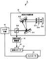
第1の実施形態のレーザ加工装置1は、図1の構成図に示すようにレーザ光源10と波長分布選択部11と照射位置制御部12と試料ステージ13とコントローラ14とを有する。被加工材料15は試料ステージ13に保持されレーザ光を導くため適宜光学系16が配置される。 The laser processing apparatus 1 according to the first embodiment includes a
レーザ光源10は、波長領域の広いレーザ光を出射するTi:Sapphireレーザである。レーザ光源10には広帯域で発振するレーザを用いるのが望ましく、Ti:Sapphireレーザの他、白色レーザ、色素レーザ等を用いてもよい。光源発振波長が広帯域であることにより照射位置制御部12による加工位置の制御幅が広がり、加工に使用する波長を選択できるため容易に入手できる波長分散素子を利用できる。 The
また、レーザ光源10にはフェムト秒やピコ秒領域のパルス幅を有する極短パルスレーザを用いるのが望ましく、Ti:Sapphireレーザの他、ファイバーレーザ等を用いてもよい。極短パルスのフェムト秒レーザでは、短パルス化のために原理的に発振パルス幅を広くする必要があり、数十nm以上の広帯域で発振する。そのため装置の改良なく広帯域のレーザ光源として利用できる。さらに、極短パルス光源を利用することで、熱伝播を抑制した高精度加工が可能となり、熱伝播によるエネルギーロスが少なく低エネルギーで加工できる。また、ナノ秒レーザではレーザ光を吸収して発生したプラズマをさらにレーザ光が吸収するプラズマ再吸収が発生して表面を損傷するのに対し、フェムト秒レーザではこれが抑制されて高精度に加工できる。また、高ピークパワーにより透明体の多光子吸収を容易に起こして低エネルギーで透明体の除去や改質ができる。 The
また、レーザ光源10は、パルス状に発振するレーザ光の他、波長変換素子により波長が変換されたレーザ光、レーザ光により発光する発光体などを利用してもよい。例えば、極短パルスレーザ光をガス導入した中空ファイバーに通過させたり、レーザ光をフォトニッククリスタルに入射する等の手段により波長を広帯域化してもよい。 Further, the
波長分布選択部11は、同一構造をもつ反射型の第1の回折格子110と第2の回折格子111と波長選択フォトマスク112と第3の回折格子113と第4の回折格子114とで構成される。第1の回折格子110は入射されるレーザ光の+1次方向への回折効率が最大となる位置に配置される。第2の回折格子111は第1の回折格子110により波長に依存して異なる角度で広がる回折光を反射して平行光にする位置に配置され、反射したレーザ光を波長ごとに異なる光路をもつ平行な帯状にして波長選択フォトマスク112に入射させる。 The wavelength distribution selection unit 11 includes a reflection type
波長選択フォトマスク112は第2の回折格子111で回折されて広がりをもつレーザ光の一部の透過を制限することにより波長を選択する。波長選択フォトマスク112は例えばCr等の金属膜を透明基板の一部に蒸着して形成される。金属膜はレーザ光の進行方向及び広がり方向に直角なスリットを設けて形成され、入射するレーザ光の一部を金属膜で反射する。波長選択フォトマスク112は製造が容易で幅広い波長域の波長を高精度に選択できる。なお、波長選択フォトマスク112は金属膜の膜厚を制御して透過率を連続的に変化させたグレーレベルマスクであってもよい。グレーレベルマスクを用いると、波長を選択できると同時に各波長の強度も制御できる。また空間的な位置により光の透過を制限するものであれば波長選択フォトマスク112の代わりに金属板、スリット、ピンホール等の素子を用いてもよい。 The
第3の回折格子113及び第4の回折格子114はそれぞれ第2の回折格子111及び第1の回折格子110と対称に配置され、波長選択フォトマスク112により波長が選択されたレーザ光を第1の回折格子110に入射される前の状態程度に収束する。なお、各回折格子は+1次光の回折効率の高いものが望ましく、各回折格子のピッチを細かくして波長選択の分解能を上げることができる。一般に回折格子は入手しやすいため装置を低コストで構成できる。反射型の回折格子を利用することで利用可能な波長領域を広くできる。反射型の回折格子の代わりに透過型の回折格子を用いてもよく、波長により空間伝播位置を変化させる素子であればホログラム素子、レンズ等を用いてもよい。 The
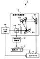
照射位置制御部12は図2の構成図に示すように投影用フォトマスク121と色消用レンズ対122と分散用レンズ123とを有する。投影用フォトマスク121は透明基板上にCr等の不透明膜を被加工材料15に投影する像面のパターンに合わせて形成したものであり、波長分布選択部11から出射されたレーザ光の一部を不透明膜で遮蔽して他の一部を透過させる。投影用フォトマスク121の代わりに一部に穴形状を有する金属マスク、透過率分布を制御したグレースケールマスク、液晶等の空間光変調器を用いたマスク等を用いてもよい。 The irradiation
色消用レンズ対122はレーザ光の発光波長領域において可能な限り色消しする構成をもち、投影用フォトマスク121から焦点距離の位置に配置される。分散用レンズ123は波長に依存して焦点距離が異なるレンズであり、レーザ光を被加工材料15に集光して照射する。レーザ光は波長に応じて被加工材料15の深さ方向の異なる位置に異なる像面を形成する。ある波長のレーザ光は分散用レンズ123に近い側に像面を形成し、他の波長のレーザ光は分散用レンズ123から遠い側に像面を形成する。このようにレーザ光の波長に依存して空間的な強度分布が異なるため、各深さにおいて全波長にわたるレーザ光強度の総和が異なる。これにより、波長分布選択部11で調整されたレーザ光の波長分布に応じて被加工材料15付近でのレーザ光の強度分布を三次元的に制御できる。 The
色消用レンズ対122及び分散用レンズ123の組み合わせは波長に応じて焦点距離が異なればレンズ、プリズム、これらの他の組み合わせ等であってもよく一部に分散のない素子を組み合わせてもよい。また、分散の大きな材料は波長に依存した屈折率の変化が大きく、焦点位置を波長により大きく変化させることができ、加工形状の制御範囲を広げるため、レーザ光の発光波長領域において分散の大きい材料を用いることが望ましい。また、複数の素子を利用することで制御範囲を広げることができる。通常のレーザ加工装置で用いられるアクロマティックレンズや対物レンズ等の高価な素子が不要で、安価な単レンズ等を用いてシンプルな構成にできる。 The combination of the
試料ステージ13は、被加工材料15を保持して移動させ、被加工材料15の加工を行う位置(加工位置)を、分散用レンズ123を通過したレーザ光が像面を形成する位置(照射位置)に配置する。試料ステージ13を二次元だけでなく三次元に移動させると、広範囲で立体的な加工できる。コントローラ14は、時間の経過に応じて試料ステージ13を移動させてレーザの加工位置を調整し、試料ステージ13の移動タイミングに同期してレーザ光源10がレーザ光を出射するタイミングを制御する。コントローラ14は、加工位置に応じた試料ステージの移動量やレーザ光のパルス数等をあらかじめ記憶している。レーザ光源10の発光波長領域、波長選択フォトマスク112により選択される波長、分散用レンズ123を通過したレーザ光の照射位置等は、被加工材料15の加工形状に合わせてあらかじめ選択する。 The
このレーザ加工装置1の動作について説明する。コントローラ14は、試料ステージ13を移動させて被加工材料15の第1番目の加工位置を照射位置に配置させて、レーザ光源10に例えば図3(a)の波長強度分布図に示すスペクトルをもつレーザ光を出射させる。レーザ光は波長分布選択部11に入射し、第1の回折格子110及び第2の回折格子111により図3(b)の位置強度分布図に示すような波長ごとに異なる光路をもつ帯状の平行光として回折されて、波長選択フォトマスク112のパターンに応じて、一部の波長の光が遮蔽されて例えば図3(c)の位置強度分布図に示すように波長λ1と波長λ2とが選択され、第3の回折格子113及び第4の回折格子114により広がりが収束され、図3(d)の波長強度分布図に示すようなスペクトルをもって照射位置制御部12に入射する。 The operation of this laser processing apparatus 1 will be described. The
投影用フォトマスク121を通過して色消しレンズ122及び分散レンズ123を通過したレーザ光は、波長に応じて被加工材料15の表面からの異なる深さに像面を形成する。例えば図4のように像面を形成する場合、図3(d)に示す波長λ1及び波長λ2の各強度及び全レーザ光強度は、図5(a)に示すように深さd1において波長λ2の強度が波長λ1の強度より強く、図5(b)に示すように深さd2において波長λ1の強度が波長λ2の強度より強く、図5(c)に示すように深さd3において波長λ1の強度と波長λ2の強度とが同等となっており、全レーザ光強度は図5(d)に示す深さd1及び図5(e)に示す深さd2において同等で、図5(f)に示すように深さd3においてこれより弱くなっている。被加工材料15は各深さにおいて全波長領域で足し合わされたレーザ光の強度に応じて加工される。すなわちあるレーザ光強度以上で被加工材料15が除去、改質等される。図4の場合、深さd1及びd2において同程度の加工がされ、深さd3では全レーザ光強度が弱いため加工されない。レーザ光は1パルスでもよく複数のパルスを連続して照射してもよい。さらに連続して加工する場合、順次試料ステージ13の移動とレーザ光の出射を繰り返す。 The laser light that has passed through the
被加工材料15に照射されるレーザ光の波長の分布を選択することで、照射位置において深さ方向のレーザ光の強度分布を制御でき、深さに応じてレーザ光が被加工材料15に与える強度を調整できる。従って、1パルスのレーザ光で被加工材料15の深さ方向に所望の形状を形成できる。試料ステージ13を深さ方向に移動させると、より広範囲な深さ方向の加工ができる。また、像面が形成される領域(加工点)から離れると面積あたりのレーザ光の強度が低下するため加工がある深さで終息し、レーザ照射を多数回繰り返しても深さを一定にして加工する領域の形状が悪化しない。波長分布選択部11において波長の違いを空間的な伝播路の違いに変換するため、空間的に伝播路の一部を遮蔽することで容易、高精度、高速、安価に波長分布を調整できる。色収差を利用するため、フェムト秒レーザ等の広帯域のレーザを用いて精密に加工できる。被加工材料15を透明体として改質を行う場合、改質領域の形状を光学系や被加工材料15を移動せずに波長分布の調整によって制御できる。 By selecting the wavelength distribution of the laser beam irradiated to the
図6の構成図に示す第2の実施形態のレーザ加工装置2が備える波長分布選択部21は、図7(a)の平面図及び図7(b)の側面図に示すような複数の波長選択フォトマスク112と移動ステージ210とを有しており、他の構成は第1の実施形態のレーザ加工装置1と同様である。移動ステージ210は複数の波長選択フォトマスク112を保持して移動させ、いずれかの波長選択フォトマスク112を矢印で示されるレーザ光の光路に挿入する。波長選択フォトマスク112は、第2の回折格子111で広げられたレーザ光の各波長の位置と、波長選択フォトマスク112が選択しようとする波長の位置とが一致するように挿入される。コントローラ14は、いずれの加工位置でどの波長選択素子を挿入させるかをあらかじめ記憶している。他の構成は第1の実施形態と同様である。 The wavelength
レーザ加工装置2の動作を説明する。コントローラ14は、試料ステージ13を移動させて被加工材料15の第1番目の加工位置を照射位置に配置させ、その加工位置に照射する波長分布を形成する波長選択フォトマスク112をレーザ光の光路に挿入するよう移動ステージ210を移動させ、レーザ光源10にレーザ光を出射させる。ここで同じ加工位置で複数の波長選択フォトマスク112を入れ替えてもよい。さらに連続して加工する場合、順次試料ステージ13の移動と波長選択フォトマスク112の挿入とレーザ光源10からのレーザ光の出射とを繰り返す。 The operation of the laser processing apparatus 2 will be described. The
被加工材料15に照射されるレーザ光の波長の分布を加工位置に応じて調整して、被加工材料15付近において深さ方向のレーザ光の強度分布を制御できため、加工位置に応じて異なる加工形状を形成できる。また同じ加工位置で被加工材料15に照射するレーザ光の波長分布を順次変化させると像面の位置が深さ方向に移動するため、被加工材料15の上面側から深さ方向に順次加工を進めること等ができる。またパターンの異なる複数の投影用フォトマスクを他の移動ステージに搭載し、加工位置とパターンとの対応を記憶したコントローラ14の指示に応じて取替えてもよい。 The distribution of the wavelength of the laser light irradiated to the
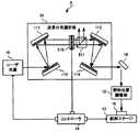
図8の構成図に示す第3の実施形態のレーザ加工装置3が備える波長分布選択部31は、偏光ビームスプリッタ310と第1の回折格子311と第2の回折格子312と波長選択フォトマスク313と1/4波長板314とミラー315とをもつ。第1の回折格子311と第2の回折格子312は第1の実施形態のレーザ加工装置1が備える回折格子と同様であり、波長選択フォトマスク313は、第1の実施形態のレーザ加工装置1が備える波長選択フォトマスク112と同様のものである。 The wavelength
偏光ビームスプリッタ310はレーザ光の偏光に対して透過率が最大となる方向に配置されてレーザ光源10側から入射されるレーザ光を第1の回折格子311に入射させる。レーザ光源10からのレーザ光が直線偏光でない場合にはあらかじめ直線偏光に変換しておくと効率がよい。第1の回折格子311は偏光ビームスプリッタ310を通過したレーザ光の+1次方向への回折効率が最大となる位置に配置する。第2の回折格子312は第1の回折格子311により波長に依存して異なる角度で広がる回折光を反射して平行光にする位置に配置され、反射したレーザ光を波長ごとに異なる光路をもつ平行な帯状のレーザ光とする。波長選択フォトマスク313は、第2の回折格子312と1/4波長板313との間に配置され、第2の回折格子312により広がりのある平行光とされたレーザ光の一部を遮蔽する。1/4波長板313は波長選択フォトマスク313を通過したレーザ光を直線偏光から円偏光に変えてミラー315に入射させて、ミラー315により入射レーザ光と同一の光路で全反射されたレーザ光を円偏光から直線偏光に変えることにより偏光方向を90度回転させる。また、第2の回折格子312及び第1の回折格子311はミラー315で反射され1/4波長板314及び波長選択フォトマスク313を通過したレーザ光を第1の回折格子311に入射される前の状態程度に収束させる。偏光ビームスプリッタ310は、第1の回折格子311側から入射されるレーザ光を反射して照射位置制御部12に入射させる。他の構成および動作は第1の実施形態と同様である。 The
図9に示す第4のレーザ加工装置4が備える波長分布選択部41は、偏光ビームスプリッタ410と1/4波長板411と第1の回折格子412と第2の回折格子413とDMD(Digital Micro-mirror Device)素子414とを有する。第1の回折格子311と第2の回折格子312は第1の実施形態のレーザ加工装置1が備える回折格子と同様である。コントローラ14は、いずれの加工位置でDMD素子のミラーをどのようなパターンに形成させるかをあらかじめ記憶している。 The wavelength
偏光ビームスプリッタ410はレーザ光の偏光に対して透過率が最大となる方向に配置されてレーザ光源10側から入射されるレーザ光を1/4波長板411に入射させる。レーザ光源10からのレーザ光が直線偏光でない場合にはあらかじめ直線偏光に変換しておくと効率がよい。1/4波長板411は偏光ビームスプリッタ410を通過したレーザ光を直線偏光から円偏光に変えて第1の回折格子412に入射させる。第1の回折格子412は1/4波長板411を通過したレーザ光の+1次方向への回折効率が最大となる位置に配置する。第2の回折格子413は第1の回折格子412により波長に依存して異なる角度で広がる回折光を反射して平行光にする位置に配置され、反射したレーザ光を波長ごとに異なる光路をもつ平行な帯状のレーザ光とする。DMD素子414は、コントローラ14からの指示に従ってミラーの向きを調整し、レーザ光の一部を入射と同一の光路で反射し、他の一部を入射と異なる方向に反射して反射光に含まれないように調整する。DMD素子414のパターンを変化させてレーザ光を任意の波長分布に調整できる。第2の回折格子413及び第1の回折格子412はDMD素子414で反射されたレーザ光を、第1の回折格子412に入射される前の状態程度に収束させる。1/4波長板411は収束されたレーザ光を円偏光から直線偏光に変えることにより偏光方向を偏光ビームスプリッタ410側からのレーザ光に対して90度傾ける。偏光ビームスプリッタ410は1/4波長板411側から入射されるレーザ光を反射して照射位置制御部12に入射させる。他の構成は第1の実施形態と同様である。 The
レーザ加工装置4の動作を説明する。コントローラ14は、試料ステージ13を移動させて被加工材料15の第1番目の加工位置を照射位置に配置させ、その加工位置に照射する波長分布を形成するミラーのパターンをDMD素子414に形成させ、レーザ光源10にレーザ光を出射させる。ここで同じ加工位置でミラーのパターンを複数回変更してレーザ光を出射させてもよい。さらに連続して加工する場合、順次試料ステージ13の移動とDMD素子414のミラーのパターンの形成とレーザ光源10からのレーザ光の出射とを繰り返す。 The operation of the laser processing apparatus 4 will be described. The
DMD素子414は単一の素子で種々の波長分布を形成でき、フォトマスク等のように複数のパターンをあらかじめ用意する必要がない。また、入手が容易であり時間の経過に従って波長分布を調整するような制御を容易に行える。なお、DMD素子414の代わりに、透過型の液晶素子、反射型の液晶素子、反射型のDMD素子、MEMS(Micro Electro Mechanical System)素子等の時間的に反射量や透過量を変化させる空間強度変調器を用いてもよい。 The
図10の構成図に示す第5のレーザ加工装置5が備える波長分布選択部51は、第1のレーザ加工装置1が備える波長分布選択部11の、第2の回折格子111と第3の回折格子113との間に配置された波長選択フォトマスク112の代わりに、透過型液晶素子510と偏光ビームスプリッタ511とをもつ。コントローラ14は、いずれの加工位置で透過型液晶素子510にどのような電圧を印加して液晶の傾きを調整するかをあらかじめ記憶している。 The wavelength
透過型液晶素子510はコントローラ14から電圧を印加されて面内の液晶の傾きを制御し、第2の回折格子412により回折されて空間的に広がりをもったレーザ光に対し、面内の透過する位置に依存した偏光を与える。透過型液晶素子510に中間値を入力することで幅広い偏光の選択ができる。偏光ビームスプリッタ511は、透過型液晶素子510を透過したレーザ光に対し、その偏光方向に依存して一部の偏光成分を反射させて他の偏光成分を透過させる。その結果、透過光の波長が所望の分布に調整される。偏光ビームスプリッタ511は、偏光分離プリズムや回折格子等の偏光分離素子であってもよい。他の構成は第1の実施形態のレーザ加工装置1と同様である。 The transmissive
レーザ加工装置5の動作を説明する。コントローラ14は、試料ステージ13を移動させて被加工材料15の第1番目の加工位置を照射位置に配置させ、その加工位置に照射する波長分布を形成する電圧を透過型液晶素子510に印加し、レーザ光源10にレーザ光を出射させる。ここで同じ加工位置で透過型液晶素子510に印加する電圧を複数回変更してレーザ光を出射させてもよい。さらに連続して加工する場合、順次試料ステージ13の移動と透過型液晶素子510への電圧の印加とレーザ光源10からのレーザ光の出射とを繰り返す。 The operation of the laser processing apparatus 5 will be described. The
透過型液晶素子510を用いることで、種々の波長分布を形成でき、フォトマスク等のように複数のパターンをあらかじめ用意する必要がない。また、入手が容易であり時間の経過に従って波長分布を調整するような制御を容易に行える。また、透過するか反射するかの2値の調整だけでなく中間値の透過量も調整できる。 By using the transmissive
図11の構成図に示す第6の実施形態のレーザ加工装置6が備える波長分布選択部61は、偏光ビームスプリッタ610と反射型の同一構造をもつ第1の回折格子611と第2の回折格子612と透過型液晶素子613とミラー614とをもつ。コントローラ14は、いずれの加工位置で透過型液晶素子613にどのような電圧を印加して液晶の傾きを調整するかをあらかじめ記憶している。 The wavelength
偏光ビームスプリッタ610はレーザ光の偏光に対して透過率が最大となる方向に配置されてレーザ光源側から入射されるレーザ光を第1の回折格子611に入射させる。レーザ光源10からのレーザ光が直線偏光でない場合にはあらかじめ直線偏光に変換しておくと効率がよい。第1の回折格子611は偏光ビームスプリッタ610を通過したレーザ光の+1次方向への回折効率が最大となる位置に配置する。第2の回折格子612は第1の回折格子により波長に依存して異なる角度で広がる回折光を反射して平行光にする位置に配置され、反射したレーザ光を波長ごとに異なる光路をもつ平行な帯状のレーザ光とする。透過型液晶素子613は、コントローラ14から電圧を印加されて面内の液晶の傾きを制御し、第2の回折格子612により回折されて空間的に広がりをもったレーザ光に対し、面内の透過する位置に依存した任意の偏光を与え、ミラー614により反射したレーザ光に対して任意の偏光を与える。透過型液晶素子613に中間値を入力することで幅広く偏光を制御できる。第2の回折格子612及び第1の回折格子611はミラー614で反射されて透過型液晶素子613を通過したレーザ光を第1の回折格子611に入射される前の状態程度に収束させる。偏光ビームスプリッタ610は、第1の回折格子611側から入射されるレーザ光に対し、その偏光方向に依存して一部の偏光成分を反射させて他の偏光成分を透過させ、波長を所望の分布に調整する。他の構成は第1の実施形態と同様である。 The
レーザ加工装置6の動作を説明する。コントローラ14は、試料ステージ13を移動させて被加工材料15の第1番目の加工位置を照射位置に配置させ、その加工位置に照射する波長分布を形成する電圧を透過型液晶素子613に印加し、レーザ光源10にレーザ光を出射させる。ここで同じ加工位置で透過型液晶素子613に印加する電圧を複数回変更してレーザ光を出射させてもよい。さらに連続して加工する場合、順次試料ステージ13の移動と透過型液晶素子613への電圧の印加とレーザ光源10からのレーザ光の出射とを繰り返す。 The operation of the laser processing apparatus 6 will be described. The
透過型液晶素子613を用いることで、種々の波長分布を形成でき、フォトマスク等のように複数のパターンをあらかじめ用意する必要がない。また、入手が容易であり時間の経過に従って波長分布を調整するような制御を容易に行える。また、透過するか反射するかの調整だけでなく透過量も調整できる。さらに、光学系が単純で1/4波長板等の素子の数を低減できる。なお、透過型液晶素子613とミラー614との組み合わせの代わりに反射型液晶素子を用いてもよい。 By using the transmissive
第7の実施形態のレーザ加工装置7が備える波長分布選択部71は、第1から第6の実施形態のレーザ加工装置が備える波長分布選択部の各回折格子の代わりにプリズムを用いる。なお、各プリズムは複数枚のプリズムを組み合わせたものであってもよい。プリズムの頂角及びプリズムの位置を調整して、プリズム通過後のレーザ光の波長に依存した広がりを制御できる。無反射コーティングすることで、ロスなく高効率で波長分布を空間強度分布に変換できる。 The wavelength distribution selection unit 71 included in the laser processing apparatus 7 of the seventh embodiment uses a prism instead of each diffraction grating of the wavelength distribution selection unit included in the laser processing apparatuses of the first to sixth embodiments. Each prism may be a combination of a plurality of prisms. By adjusting the apex angle of the prism and the position of the prism, the spread depending on the wavelength of the laser beam after passing through the prism can be controlled. By applying non-reflective coating, the wavelength distribution can be converted into the spatial intensity distribution with high efficiency without loss.
例えば、第1の実施形態のレーザ加工装置1が備える第1の回折格子110、第2の回折格子111、第3の回折格子113、第4の回折格子114を図12の構成図に示すようにそれぞれ互いに同一構造の第1のプリズム710、第2のプリズム711、第3のプリズム712、第4のプリズム713で置き換える場合、第1のプリズム710は入射されるレーザ光を、波長に依存した異なる角度の広がりを持たせて出射する。第2のプリズム711は第1のプリズム710により出射されて広がるレーザ光を屈折させて平行光にする位置に配置され、屈折したレーザ光を波長ごとに異なる光路をもつ平行な帯状として波長選択フォトマスク112に入射させる。第3のプリズム712及び第4のプリズム713はそれぞれ第2のプリズム711及び第1のプリズム710と対称に配置され、波長が選択されたレーザ光を収束して第1のプリズム710に入射される前の状態に戻す。他の構成及び動作は第1の実施形態と同様であり、第2及び第5の実施形態についても同様に置き換えられる。 For example, the
また例えば、第3の実施形態で第1の回折格子311と第2の回折格子312とを図13の構成図に示すようにそれぞれ互いに同一構造の第1のプリズム714と第2のプリズム715とで置き換える場合、偏光ビームスプリッタ310はレーザ光の偏光に対して透過率が最大となる方向に配置されてレーザ光源側から入射されるレーザ光を第1のプリズム714に入射させる。第1のプリズム714は入射されるレーザ光を、波長に依存した異なる角度の広がりを持たせて出射する。第2のプリズム715は第1のプリズム714により出射されて広がるレーザ光を屈折させて平行光にする位置に配置され、屈折したレーザ光を波長ごとに異なる光路をもつ平行な帯状として1/4波長板314に入射させる。波長選択フォトマスク313は、第1の実施形態のレーザ加工装置1が備えるものと同様であり、第2のプリズム715とミラー315との間に配置され、第2のプリズム715により広がりのある平行光とされたレーザ光の一部を遮蔽する。1/4波長板314は波長選択フォトマスク313を通過したレーザ光を直線偏光から円偏光に変えてミラー315に入射させて、ミラー315により入射レーザ光と同一の光路で全反射されたレーザ光を円偏光から直線偏光に変えることにより偏光方向を90度回転させる。また、第2のプリズム715及び第1のプリズム714はミラー315で反射され1/4波長板314及び波長選択フォトマスク313を通過したレーザ光を第1のプリズム714に入射される前の状態程度に収束させる。偏光ビームスプリッタ310は、第1のプリズム714側から入射されるレーザ光を反射して照射位置制御部12に入射させる。他の構成及び動作は第3の実施形態と同様であり、第4及び第6の実施形態についても同様に置き換えられる。 Further, for example, in the third embodiment, the
図14(a)の構成図に示す第8の実施形態のレーザ加工装置8が備える波長分布選択部81は波長フィルタ810を有する。波長フィルタ810は、色ガラスフィルタや多層膜を利用した干渉フィルタ等を用いて形成されて薄膜を利用することで赤外から深紫外、X線領域のレーザまで利用でき、レーザ光源からレーザ光の入射を受けて波長に依存して強度を変化させて出射する。波長フィルタは複数枚合わせて形成してもよい。波長フィルタを用いることで装置構成がシンプルとなりシステムを安価にできる。波長分布選択部81以外の構成及び動作は第1の実施形態のレーザ加工装置1と同様である。また図14(b)の構成図に示すように波長分布選択部91は、複数の波長フィルタ810を移動ステージ811に搭載させることも可能である。移動ステージ811は複数の波長フィルタ810を保持して移動し、いずれかの波長フィルタ810をレーザ光の光路に挿入する。コントローラ14は、いずれの加工位置でどの波長フィルタを挿入させるかをあらかじめ記憶している。他の構成及び動作は第2の実施形態と同様である。波長フィルタの交換により被加工材料15の深さ方向への加工形状を容易に変えられる。 The wavelength
図15に示す第9の実施形態のレーザ加工装置9が備える波長分布選択部91は、NDフィルター、偏光分離素子、グレーマスク等の強度調整素子92を有する。例えば第1の実施形態のレーザ加工装置1にグレーマスクを強度調整措置として用いる場合、第2の回折格子111から反射されたレーザ光は、波長選択フォトマスク112に入射される前に強度調整素子92を通過する。強度調整素子92の透過率に両端部分で大きく中間部分で低くなるような傾斜をもたせると、図16(a)のような波長分布を持つ強度調整素子92通過前のレーザ光が、強度調整素子92通過後に図16(b)のような波長分布をもち、波長分布が平滑化される。波長に依存して強度を調整することで加工位置での強度分布を制御できるため加工形状を精密に制御できる。なお、複数の強度調整素子92を移動ステージで移動させてレーザ照射や被加工材料15の移動と同期して制御することで、加工位置ごとに強度分布を調整できる。 The wavelength
図17の構成図に示す第10の実施形態のレーザ加工装置93が備える照射位置制御部94は、図18の構成図に示すようにガルバノミラー95と分散用レンズ123とを有し、他の構成は第2の実施形態のレーザ加工装置2と同様である。なお他の実施形態のレーザ加工装置にガルバノミラー95を用いてもよい。 The irradiation position control unit 94 provided in the
図19に示すようにガルバノミラー95は、コントローラの指示に従って回転して波長分布選択部11から入射されたレーザ光を反射し、回転の角度に応じて分散用レンズ123に入射する位置及び角度を変化させ、被加工材料15への照射位置を移動させる。コントローラ14は、各加工位置におけるガルバノミラー95の回転量をあらかじめ記憶している。 As shown in FIG. 19, the
レーザ加工装置93の動作を説明する。コントローラ14は、ガルバノミラー95を回転させて照射位置を設定し、その照射位置における波長分布を形成する波長選択フォトマスク112をレーザ光の光路に挿入するよう移動ステージ210を移動させ、レーザ光源10にレーザ光を出射させる。ここで同じ照射位置で複数の波長選択フォトマスク112を入れ替えてもよい。さらに連続して加工する場合、順次ガルバノミラー95の回転と波長選択フォトマスク112の挿入とレーザ光源10からのレーザ光の出射とを繰り返す。 The operation of the
ガルバノミラー95の回転によりレーザ光の照射位置を移動させるため、試料ステージ13を移動しなくても被加工材料15の異なる加工位置を高速に加工でき、大面積を容易に加工できる。さらに試料ステージを移動させることで大面積を加工できる。ガルバノミラー95はポリゴンミラー等の他のレーザ光操作部であってもよい。 Since the irradiation position of the laser beam is moved by the rotation of the
第11の実施形態のレーザ加工装置が備える照射位置制御部は、複数の厚さの異なる分散用レンズ123を搭載してコントローラ14からの指示によりいずれかのレンズをレーザ光の光路に挿入するレンズ移動ステージを有する。コントローラ14はいずれの加工位置でどの厚さの分散用レンズ123を挿入するかをあらかじめ記憶している。 The irradiation position control unit provided in the laser processing apparatus according to the eleventh embodiment includes a plurality of
この照射位置制御部を用いた図6に示す第2の実施形態にレーザ加工装置の動作を説明する。コントローラ14は、試料ステージ13を移動させて被加工材料15の第1番目の加工位置を照射位置に配置させ、その加工位置に照射する波長分布を形成する波長選択フォトマスク112をレーザ光の光路に挿入するよう移動ステージ210を移動させ、レンズ移動ステージを移動させて各加工位置における加工形状に対応する分散用レンズ123をレーザ光の光路に挿入し、レーザ光源10にレーザ光を出射させる。ここで同じ加工位置で波長選択フォトマスク112を複数回入れ替えてもよく、分散用レンズ123を複数回入れ替えてもよい。さらに連続して加工する場合、順次試料ステージ13の移動と波長選択フォトマスク112の挿入と分散用レンズ123の挿入と、レーザ光源10からのレーザ光の出射とを繰り返す。なお、他の実施形態のレーザ加工装置に本実施形態の照射位置制御部を用いることもできる。 The operation of the laser processing apparatus will be described in the second embodiment shown in FIG. 6 using this irradiation position control unit. The
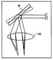
一般に、図19に示すように薄い分散用レンズ96を用いた場合と厚い分散用レンズ97を用いた場合とでは、第1の波長の光路98及び第2の波長の光路99が異なり、薄い分散用レンズ96の波長に依存した焦点距離の差d4よりも厚い分散用レンズ97の波長に依存した焦点距離の差d5の方が大きくなる。そのため厚さの異なる分散用レンズを選択することにより加工深さの調整範囲を選択できる。分散用レンズ123の材料はレーザ光の発光波長領域に対して、分散の大きい材料が望ましく、一部に分散のない素子と組み合わせてもよい。なお、分散用レンズ123と被加工材料15との間においてレーザ光の一部または全部を平行透明基板を配置してもよい。平行透明基板はガラス基板等の材料を用いて安価に形成でき、レーザ光の光路の一部に挿入されることで加工材料の面内の複数の領域で加工深さの調整範囲を変えられる。 In general, as shown in FIG. 19, when the
第12の実施形態のレーザ加工装置が備える照射位置制御部は、第1から第12の実施形態の照射位置制御部が有するレンズの代わりに、基板上に透明パターンを形成した平面型フレネルレンズやホログラム素子等の回折素子を有する。ホログラム素子98は図20に示すように、形成されたパターンに応じて波長に依存して照射位置を異ならせることができ、また、同一の波長のレーザ光を複数の照射位置に照射できる。複数の照射位置に照射することで、同時に被加工材料15の異なる位置を加工できる。また、波長ごとに強度を調整することで、照射位置ごとに異なる形状に加工できる。これにより位置と深さとが異なる領域を同時に立体的に加工できる。照射位置は波長ごとに離れていても重なっていてもよい。 The irradiation position control unit included in the laser processing apparatus of the twelfth embodiment is a planar Fresnel lens in which a transparent pattern is formed on a substrate, instead of the lenses included in the irradiation position control units of the first to twelfth embodiments. It has a diffraction element such as a hologram element. As shown in FIG. 20, the
以上に説明した第1から第12の実施形態のレーザ加工装置により、被加工材料15に微細な穴形状を高精度に配置した構造体や、被加工材料15の屈折率を変調した変質領域を高精度に配置した構造体を作成できる。穴形状や変質領域の形状はドット状、線状、線を重ねた面状等とすることができる。加工される深さは均一である必要はなく部分的に深さを変化させてもよい。微細な穴形状を高精度に配置した構造体は、光ディスクのスタンパ、回折素子、MEMS素子、センサー素子等、マイクロ流路等デバイス、これら素子の複製用原版としての機能をもたせられる。変質領域を高精度に配置した構造体は、屈折率変調型回折素子、ホログラム素子としての機能をもたせられる。 By the laser processing apparatus of the first to twelfth embodiments described above, a structure in which fine hole shapes are arranged in the
また、被加工材料15を透明材料とし、入射されるレーザ光の多光子吸収を用いて透明材料に穴形状の形成、改質、屈折率変調を誘起できる。このときレーザは短パルスレーザを用いることが望ましい。透明材料とはレーザ光に対する吸収の少ない材料であり、レーザ光の波長が可視域の場合にはガラスや透明ポリマー等を利用でき、レーザ光の波長が赤外域の場合にはSi基板等を利用できる。レーザ光は複数回照射しても、被加工材料15の移動と同期して照射してもよい。 Further, the
加工用レーザ光に対して透明な材料を被加工物に用い、さらに加工焦点位置を透明体内部に設定することで透明体の内部側にも加工位置を設定することができる。加工はある敷居レーザフルエンス以上の点でおきることから、表面から内部まで同時に加工することが可能となる。このとき波長分布を制御することで、深さ方向の任意の位置に照射強度を調整することが可能で、加工形状の制御性を高くすることができる。このときレーザ光を複数回照射した場合でもある照射フルエンス以下の領域は加工されないことから、加工位置をある位置で止めることができる。内部改質の場合には、これにより改質量を増すことができる。これは改質を屈折率変調に利用する場合も同様であり、複数回照射することで、深さを変えることなく、屈折率変化量を大きくすることが可能となる By using a material transparent to the processing laser beam for the workpiece, and further setting the processing focal position inside the transparent body, the processing position can also be set on the inner side of the transparent body. Since the processing is performed at a point more than a certain threshold laser fluence, it is possible to perform processing from the surface to the inside at the same time. At this time, by controlling the wavelength distribution, the irradiation intensity can be adjusted to an arbitrary position in the depth direction, and the controllability of the processing shape can be enhanced. At this time, since the region below the irradiation fluence, which is the case where the laser beam is irradiated a plurality of times, is not processed, the processing position can be stopped at a certain position. In the case of internal reforming, this can increase the amount of reforming. The same applies to the case where the modification is used for refractive index modulation. By irradiating a plurality of times, the amount of change in the refractive index can be increased without changing the depth.
この発明は、光ディスクの記録ピットの形成及びその原盤である光ディスク成形用スタンパの形成、表面レリーフ型回折格子や回折型ホログラム等の光学素子の形成及びその原盤の形成、マイクロマシン、マイクロセンサー、マイクロ流路やマイクロ化学用微細構造体等の微細立体デバイスの形成並びに表面屈折率変調素子の形成、その他の微細形状を必要とする高精度部品の形成に用いることができる。 The present invention relates to formation of recording pits on an optical disk and formation of an optical disk molding stamper that is a master disk, formation of optical elements such as a surface relief type diffraction grating and a diffraction hologram, and formation of the master disk, micromachine, microsensor, micro flow It can be used for forming fine three-dimensional devices such as paths and microchemical microstructures, surface refractive index modulation elements, and other high-precision parts that require fine shapes.
1;レーザ加工装置、2;レーザ加工装置、3;レーザ加工装置、
4;レーザ加工装置、5;レーザ加工装置、6;レーザ加工装置、
7;レーザ加工装置、8;レーザ加工装置、9;レーザ加工装置、
10;レーザ光源、11;波長分布選択部、12;照射位置制御部、
13;試料ステージ、14;コントローラ、15;被加工材料、16;光学系、
21;波長分布選択部、31;波長分布選択部、41;波長分布選択部、
51;波長分布選択部、61;波長分布選択部、71;波長分布選択部、
81;波長分布選択部、91;波長分布選択部、92;強度調整素子、
93;レーザ加工装置、94;照射位置制御部、95;ガルバノミラー、
96;薄い分散用レンズ、97;厚い分散用レンズ、98;ホログラム素子、
110;第1の回折格子、111;第2の回折格子、
112;波長選択フォトマスク、113;第3の回折格子、
114;第4の回折格子、121;投影用フォトマスク、
122;色消し用レンズ対、123;分散用レンズ、210;移動ステージ、
310;偏光ビームスプリッタ、311;第1の回折格子、
312;第2の回折格子、313;波長選択フォトマスク、
314;1/4波長板、315;ミラー、410;偏光ビームスプリッタ、
411;1/4波長板、412;第1の回折格子、413;第2の回折格子、
414;DMD素子、510;透過型液晶素子、
511;偏光ビームスプリッタ、610;偏光ビームスプリッタ、
611;第1の回折格子、612;第2の回折格子、613;透過型液晶素子、
614;ミラー、710;第1のプリズム、711;第2のプリズム、
712;第3のプリズム、713;第4のプリズム、714;第1のプリズム、
715;第2のプリズム、810;波長フィルタ、811;移動ステージ
1; laser processing apparatus, 2; laser processing apparatus, 3; laser processing apparatus,
4; Laser processing device, 5; Laser processing device, 6; Laser processing device,
7; Laser processing apparatus, 8; Laser processing apparatus, 9; Laser processing apparatus,
10; Laser light source; 11; Wavelength distribution selection unit; 12; Irradiation position control unit;
13; sample stage, 14; controller, 15; work material, 16; optical system,
21; wavelength distribution selection unit, 31; wavelength distribution selection unit, 41; wavelength distribution selection unit,
51; wavelength distribution selection unit; 61; wavelength distribution selection unit; 71; wavelength distribution selection unit;
81; wavelength distribution selection unit, 91; wavelength distribution selection unit, 92; intensity adjustment element,
93; Laser processing apparatus, 94; Irradiation position control unit, 95; Galvano mirror,
96; thin dispersion lens, 97; thick dispersion lens, 98; hologram element,
110; first diffraction grating, 111; second diffraction grating,
112; wavelength selective photomask; 113; third diffraction grating;
114; fourth diffraction grating, 121; projection photomask;
122; achromatic lens pair, 123; dispersion lens, 210; moving stage,
310; polarizing beam splitter; 311; first diffraction grating;
312; second diffraction grating, 313; wavelength selective photomask,
314; quarter wave plate, 315; mirror, 410; polarizing beam splitter,
411; 1/4 wavelength plate, 412; first diffraction grating, 413; second diffraction grating,
414; DMD element, 510; transmissive liquid crystal element,
511; polarizing beam splitter, 610; polarizing beam splitter,
611; first diffraction grating, 612; second diffraction grating, 613; transmissive liquid crystal element,
614; mirror, 710; first prism, 711; second prism,
712; a third prism, 713; a fourth prism, 714; a first prism,
715; second prism, 810; wavelength filter, 811; moving stage
Claims (6)
Translated fromJapaneseレーザ光源と波長分布選択手段及び照射位置調整手段を有し、
前記レーザ光源は、広い波長領域のレーザ光を前記波長分布選択手段に出射し、
前記波長分布選択手段は前記レーザ光源から出射されたレーザ光から被加工材料の加工深さに応じて少なくとも2つの異なる波長のレーザ光を選択し、選択した異なる波長のレーザ光を照射位置調整手段に出射し、
前記照射位置調整手段は入射したレーザ光を波長毎に異なる焦点距離で集光して被加工材料に照射することを特徴とするレーザ加工装置。In a laser processing apparatus for processing by irradiating a workpiece with laser light,
A laser light source, wavelength distribution selection means and irradiation position adjustment means;
The laser light source emits laser light in a wide wavelength region to the wavelength distribution selection unit,
The wavelength distribution selecting unit selectsat least two laser beams having different wavelengths from the laser beam emitted from the laser light source according to the processing depth of the material to be processed, and irradiatesthe selected laser beams having different wavelengths. To
The irradiation position adjusting means condenses incident laser light at different focal lengths for each wavelength and irradiates the material to be processed.
前記光分散手段は前記レーザ光源から入射されたレーザ光を波長ごとに異なる平行光束に分散して前記空間的波長選択手段へ出射し、
前記空間的波長選択手段は前記光分散手段から入射された平行光束から少なくとも2つの異なる波長の平行光束を選択して前記光収束手段へ出射し、
前記光収束手段は入射された異なる波長の平行光束を収束させて前記照射位置調整手段に出射する請求項1記載のレーザ加工装置。The wavelength distribution selection means has light dispersion means, spatial wavelength selection means, and light convergence means,
The light dispersion means disperses thelaser light incident from the laser light source into different parallel light fluxes for each wavelength and emits them to the spatial wavelength selection means,
The spatial wavelength selection means selectsat least two parallel light fluxes having different wavelengths from the parallel light flux incident from the light dispersion means and emits them to the light convergence means,
The laser processing apparatus according to claim 1, wherein the light converging unit converges incidentparallel light beams havingdifferent wavelengths and outputs the convergedparallel light beams to the irradiation position adjusting unit.
前記偏光分離素子は前記レーザ光源から入射されたレーザ光を直線偏光に変換して前記光分散収束手段に出射し、
前記光分散収束手段は前記偏光分離素子から入射されたレーザ光を波長ごとに異なる平行光束に分散して前記空間的波長選択手段へ出射し、
前記空間的波長選択手段は前記光分散収束手段から入射された前記平行光束から少なくとも2つの異なる波長の平行光束を選択して前記1/4波長板に出射し、
前記1/4波長板は前記空間的波長選択手段から入射されたレーザ光を円偏光に変換して前記ミラーに照射し、
前記ミラーは入射されたレーザ光を同一の光路へ反射し、
前記1/4波長板は前記ミラーから入射されたレーザ光を直線偏光に変換して前記空間的波長選択手段に出射し、
前記光分散収束手段は前記空間的波長選択手段から入射される平行光束を収束させて前記偏光分離素子へ出射し、
前記偏光分離素子は前記光分散収束手段から入射されたレーザ光を前記照射位置制御部へ出射し、
前記偏光分離素子は前記光分散収束手段から入射されたレーザ光を前記照射位置制御部へ出射する請求項1記載のレーザ加工装置。The wavelength distribution selection means includes a polarization separation element, a light dispersion and convergence means, a spatial wavelength selection means, aquarter wavelength plate, and a mirror,
The polarization separation element converts the laser light incident from the laser light source into linearly polarized light and emits it to the light dispersion converging means,
The light dispersion converging means disperses thelaser light incident from the polarization separation element intodifferent parallel light fluxes for each wavelength and emits them to the spatial wavelength selection means,
The spatial wavelength selection unit selectsat least two parallel light beams having different wavelengths from the parallel light beams incident from the light dispersion and convergence unit, and outputs the parallel light beams to the quarter wavelength plate .
The quarter-wave plate converts the laser light incident from the spatial wavelength selection means into circularly polarized light and irradiates the mirror,
The mirror reflects incident laser light to the same optical path,
The quarter-wave plate converts the laser light incident from the mirror into linearly polarized light and emits it to the spatial wavelength selection means,
The light dispersion converging means converges the parallel light beam incident from the spatial wavelength selecting means and emits it to the polarization separation element,
The polarization separation element emits the laser beam incident from the light dispersion and convergence means to the irradiation position control unit,
The laser processing apparatus according to claim 1, wherein the polarization beam splitting element emits the laser beam incident from the light dispersion converging unit to the irradiation position control unit.
前記偏光分離素子は前記レーザ光源から入射されたレーザ光を直線偏光に変換して前記1/4波長板に出射し、The polarization separation element converts the laser light incident from the laser light source into linearly polarized light and emits it to the quarter-wave plate,
前記1/4波長板は前記偏光分離素子から入射されたレーザ光を円偏光に変換して前記光分散収束手段に照射し、The quarter-wave plate converts the laser light incident from the polarization separation element into circularly polarized light and irradiates the light dispersion and convergence means,
前記光分散収束手段は前記偏光分離素子から入射されたレーザ光を波長ごとに異なる平行光束に分散して前記デジタルマイクロミラーデバイスへ出射し、The light dispersion converging means disperses the laser light incident from the polarization separation element into different parallel light fluxes for each wavelength and emits them to the digital micromirror device,
前記デジタルマイクロミラーデバイスは独立して傾きが制御される複数のミラーをもち被加工材料の加工位置に応じて各ミラーの傾きを制御して前記光分散収束手段から入射された前記平行光束から少なくとも2つの異なる波長の平行光束を選択して入射光と同一の光路に反射し、The digital micromirror device has a plurality of mirrors whose tilts are independently controlled, controls at least the tilt of each mirror according to the processing position of the material to be processed, and at least from the parallel light flux incident from the light dispersion and converging means Select two parallel light beams of different wavelengths and reflect them in the same optical path as the incident light,
前記光分散収束手段は前記デジタルマイクロミラーデバイスから入射される平行光束を収束させて前記1/4波長板へ出射し、The light dispersion converging means converges the parallel light beam incident from the digital micromirror device and emits it to the quarter wavelength plate,
前記1/4波長板は前記光分散収束手段から入射されたレーザ光を直線偏光に変換して前記偏光分離素子に照射し、The quarter-wave plate converts the laser light incident from the light dispersion and converging means into linearly polarized light and irradiates the polarization separation element
前記偏光分離素子は1/4波長板から入射されたレーザ光を前記照射位置制御部へ出射する請求項1記載のレーザ加工装置。The laser processing apparatus according to claim 1, wherein the polarization separation element emits laser light incident from a quarter-wave plate to the irradiation position control unit.
前記偏光分離素子は前記レーザ光源から入射されたレーザ光を直線偏光に変換して前記光分散収束手段へ出射し、
前記光分散収束手段は前記偏光分離素子から入射されたレーザ光を波長ごとに異なる平行光束に分散して前記反射型液晶素子へ出射し、
前記反射型液晶素子は独立して液晶の傾きが制御される複数の領域をもち被加工材料の加工位置に応じて各領域の液晶の傾きを制御して前記光分散収束手段から入射された平行光束から少なくとも2つの異なる波長の平行光束を選択して偏光方向を90度回転して入射光と同一の光路に反射し、
前記光分散収束手段は前記反射型液晶素子から入射される平行光束を収束させて前記偏光分離素子へ出射し、
前記偏光分離素子は前記光分散収束手段から入射されたレーザ光を前記照射位置制御部へ出射する請求項1記載のレーザ加工装置。The wavelength distribution selection means has a polarization separation element, a light dispersion and convergence means, and a reflective liquid crystal element ,
The polarization separation element converts the laser light incident from the laser light source into linearly polarized light and emits it to the light dispersion and convergence means.
The light dispersion and converging means disperses the laser light incident from the polarization separation element into different parallel light fluxes for each wavelength and emits them to the reflective liquid crystal element,
The reflective liquid crystal element has a plurality of regions in which the tilt of the liquid crystal is controlled independently, and controls the tilt of the liquid crystal in each region according to the processing position of the material to be processed, and is incident from the light dispersion and convergence means. Select at least two parallel light fluxes of different wavelengths from the light flux, rotate the polarization direction by 90 degrees and reflect it to the same optical path as the incident light,
The light dispersion converging means converges the parallel light beam incident from the reflective liquid crystal element and emits it to the polarization separation element,
The laser processing apparatus according to claim 1, wherein the polarization beam splitting element emits the laser beam incident from the light dispersion converging unit to the irradiation position control unit.
前記光分散手段は前記レーザ光源から入射されたレーザ光を波長ごとに異なる平行光束に分散して前記空間的波長選択手段へ出射し、The light dispersion means disperses the laser light incident from the laser light source into different parallel light fluxes for each wavelength and emits them to the spatial wavelength selection means,
前記空間的波長選択手段は透過型液晶素子と偏光分離素子とを有し、前記透過型液晶素子は独立して液晶の傾きが制御される複数の領域をもち被加工材料の加工位置に応じて各領域の液晶の傾きを制御して前記光分散手段から入射された平行光束から少なくとも2つの異なる波長の平行光束の偏光方向を90度回転して前記偏光分離素子に出射し、前記偏光分離素子は前記透過型液晶素子から入射したレーザ光のうち偏光方向を90度回転した波長のレーザ光のみを前記光収束手段へ出射し、The spatial wavelength selecting means has a transmissive liquid crystal element and a polarization separating element, and the transmissive liquid crystal element has a plurality of regions in which the inclination of the liquid crystal is independently controlled according to the processing position of the work material. By controlling the tilt of the liquid crystal in each region and rotating the polarization directions of the parallel light beams of at least two different wavelengths by 90 degrees from the parallel light beams incident from the light dispersion means, the light is emitted to the polarization separation element, and the polarization separation element Emits only the laser light having a wavelength obtained by rotating the polarization direction by 90 degrees out of the laser light incident from the transmissive liquid crystal element, to the light converging means,
前記光収束手段は前記空間的波長選択手段から入射された異なる波長の平行光束を収束させて前記照射位置調整手段に出射する請求項1に記載のレーザ加工装置。2. The laser processing apparatus according to claim 1, wherein the light converging unit converges parallel light beams having different wavelengths incident from the spatial wavelength selection unit and outputs the converged light beams to the irradiation position adjusting unit.
Priority Applications (1)
| Application Number | Priority Date | Filing Date | Title |
|---|---|---|---|
| JP2004019193AJP4456881B2 (en) | 2004-01-28 | 2004-01-28 | Laser processing equipment |
Applications Claiming Priority (1)
| Application Number | Priority Date | Filing Date | Title |
|---|---|---|---|
| JP2004019193AJP4456881B2 (en) | 2004-01-28 | 2004-01-28 | Laser processing equipment |
Publications (2)
| Publication Number | Publication Date |
|---|---|
| JP2005211909A JP2005211909A (en) | 2005-08-11 |
| JP4456881B2true JP4456881B2 (en) | 2010-04-28 |
Family
ID=34903484
Family Applications (1)
| Application Number | Title | Priority Date | Filing Date |
|---|---|---|---|
| JP2004019193AExpired - Fee RelatedJP4456881B2 (en) | 2004-01-28 | 2004-01-28 | Laser processing equipment |
Country Status (1)
| Country | Link |
|---|---|
| JP (1) | JP4456881B2 (en) |
Families Citing this family (10)
| Publication number | Priority date | Publication date | Assignee | Title |
|---|---|---|---|---|
| JP4721844B2 (en)* | 2005-09-22 | 2011-07-13 | 株式会社牧野フライス製作所 | Combined processing machine |
| JP2008135125A (en) | 2006-11-29 | 2008-06-12 | Ricoh Co Ltd | Optical head, optical disc apparatus, and information processing apparatus |
| JP4402708B2 (en) | 2007-08-03 | 2010-01-20 | 浜松ホトニクス株式会社 | Laser processing method, laser processing apparatus and manufacturing method thereof |
| JP5148575B2 (en)* | 2009-09-15 | 2013-02-20 | 浜松ホトニクス株式会社 | Laser processing method and laser processing apparatus |
| JP2013515612A (en)* | 2009-12-23 | 2013-05-09 | イムラ アメリカ インコーポレイテッド | Laser-based pattern formation using optical element structure and focused beam |
| JP5536443B2 (en)* | 2009-12-29 | 2014-07-02 | 株式会社ジャパンディスプレイ | Liquid crystal display panel and manufacturing method thereof |
| JP5255109B2 (en)* | 2011-12-05 | 2013-08-07 | 浜松ホトニクス株式会社 | Laser processing method, laser processing apparatus and manufacturing method thereof |
| JP6430790B2 (en)* | 2014-11-25 | 2018-11-28 | 株式会社ディスコ | Laser processing equipment |
| WO2019100067A1 (en)* | 2017-11-20 | 2019-05-23 | Ipg Photonics Corporation | System and method laser for processing of materials |
| JP7442322B2 (en) | 2020-01-28 | 2024-03-04 | 株式会社ディスコ | Laser processing equipment and laser processing method |
- 2004
- 2004-01-28JPJP2004019193Apatent/JP4456881B2/ennot_activeExpired - Fee Related
Also Published As
| Publication number | Publication date |
|---|---|
| JP2005211909A (en) | 2005-08-11 |
Similar Documents
| Publication | Publication Date | Title |
|---|---|---|
| JP4716663B2 (en) | Laser processing apparatus, laser processing method, and structure manufactured by the processing apparatus or processing method | |
| Salter et al. | Adaptive optics in laser processing | |
| US20220227051A1 (en) | Method and Device for Producing a Three-Dimensional Object in an Optically Reactive Starting Material | |
| Flamm et al. | Structured light for ultrafast laser micro-and nanoprocessing | |
| JP6977609B2 (en) | Light irradiation device, light processing device using light irradiation device, light irradiation method, and light processing method | |
| KR102132846B1 (en) | Machining device and method for laser machining a surface | |
| US6951627B2 (en) | Method of drilling holes with precision laser micromachining | |
| CN111992873B (en) | Optical system for beam shaping | |
| CN107003531B (en) | System for asymmetrical optical beam shaping | |
| US7072566B2 (en) | Ultrashort-pulse laser-working method and apparatus and structural bodies produced by using the same | |
| JP4761432B2 (en) | Laser processing equipment | |
| US7880117B2 (en) | Method and apparatus of drilling high density submicron cavities using parallel laser beams | |
| DK2976176T3 (en) | Method and apparatus for preparing a structure on the surfaces of components with a laser beam | |
| CN111604583B (en) | Dual-wavelength femtosecond laser color marking device | |
| JP4647965B2 (en) | Laser processing method, laser processing apparatus, and structure manufactured thereby | |
| JP2006068762A (en) | Laser processing method and laser processing apparatus | |
| JP2007531008A (en) | Method for controlling hole shape during ultrafast laser processing by manipulating beam polarization | |
| JP4456881B2 (en) | Laser processing equipment | |
| CN111526979A (en) | Systems and methods for sub-micron additive manufacturing | |
| CN113396028A (en) | Device and method for laser beam shaping | |
| JP4736633B2 (en) | Laser irradiation device | |
| Kondo et al. | Three-dimensional microfabrication by femtosecond pulses in dielectrics | |
| CN116430514A (en) | Femtosecond laser direct-writing fiber grating preparation device and method | |
| JP4477893B2 (en) | LASER PROCESSING METHOD AND DEVICE, AND STRUCTURE MANUFACTURING METHOD USING LASER PROCESSING METHOD | |
| JP4436162B2 (en) | Laser processing equipment |
Legal Events
| Date | Code | Title | Description |
|---|---|---|---|
| A621 | Written request for application examination | Free format text:JAPANESE INTERMEDIATE CODE: A621 Effective date:20070109 | |
| A977 | Report on retrieval | Free format text:JAPANESE INTERMEDIATE CODE: A971007 Effective date:20090204 | |
| A131 | Notification of reasons for refusal | Free format text:JAPANESE INTERMEDIATE CODE: A131 Effective date:20090526 | |
| A521 | Written amendment | Free format text:JAPANESE INTERMEDIATE CODE: A523 Effective date:20090617 | |
| RD02 | Notification of acceptance of power of attorney | Free format text:JAPANESE INTERMEDIATE CODE: A7422 Effective date:20091207 | |
| RD04 | Notification of resignation of power of attorney | Free format text:JAPANESE INTERMEDIATE CODE: A7424 Effective date:20100115 | |
| TRDD | Decision of grant or rejection written | ||
| A01 | Written decision to grant a patent or to grant a registration (utility model) | Free format text:JAPANESE INTERMEDIATE CODE: A01 Effective date:20100129 | |
| A01 | Written decision to grant a patent or to grant a registration (utility model) | Free format text:JAPANESE INTERMEDIATE CODE: A01 | |
| A61 | First payment of annual fees (during grant procedure) | Free format text:JAPANESE INTERMEDIATE CODE: A61 Effective date:20100208 | |
| FPAY | Renewal fee payment (event date is renewal date of database) | Free format text:PAYMENT UNTIL: 20130212 Year of fee payment:3 | |
| R150 | Certificate of patent or registration of utility model | Free format text:JAPANESE INTERMEDIATE CODE: R150 | |
| FPAY | Renewal fee payment (event date is renewal date of database) | Free format text:PAYMENT UNTIL: 20130212 Year of fee payment:3 | |
| FPAY | Renewal fee payment (event date is renewal date of database) | Free format text:PAYMENT UNTIL: 20140212 Year of fee payment:4 | |
| LAPS | Cancellation because of no payment of annual fees |