JP4456188B2 - Fuel cell stack - Google Patents
Fuel cell stackDownload PDFInfo
- Publication number
- JP4456188B2 JP4456188B2JP26184298AJP26184298AJP4456188B2JP 4456188 B2JP4456188 B2JP 4456188B2JP 26184298 AJP26184298 AJP 26184298AJP 26184298 AJP26184298 AJP 26184298AJP 4456188 B2JP4456188 B2JP 4456188B2
- Authority
- JP
- Japan
- Prior art keywords
- fuel cell
- cell stack
- flow path
- fuel
- gas flow
- Prior art date
- Legal status (The legal status is an assumption and is not a legal conclusion. Google has not performed a legal analysis and makes no representation as to the accuracy of the status listed.)
- Expired - Lifetime
Links
Images


Classifications
- Y—GENERAL TAGGING OF NEW TECHNOLOGICAL DEVELOPMENTS; GENERAL TAGGING OF CROSS-SECTIONAL TECHNOLOGIES SPANNING OVER SEVERAL SECTIONS OF THE IPC; TECHNICAL SUBJECTS COVERED BY FORMER USPC CROSS-REFERENCE ART COLLECTIONS [XRACs] AND DIGESTS
- Y02—TECHNOLOGIES OR APPLICATIONS FOR MITIGATION OR ADAPTATION AGAINST CLIMATE CHANGE
- Y02E—REDUCTION OF GREENHOUSE GAS [GHG] EMISSIONS, RELATED TO ENERGY GENERATION, TRANSMISSION OR DISTRIBUTION
- Y02E60/00—Enabling technologies; Technologies with a potential or indirect contribution to GHG emissions mitigation
- Y02E60/30—Hydrogen technology
- Y02E60/50—Fuel cells
Landscapes
- Fuel Cell (AREA)
Description
Translated fromJapanese【0001】
【発明の属する技術分野】
本発明は、固体高分子電解質膜をアノード側電極とカソード側電極で挟んで構成される単位燃料電池セルとセパレータとを、交互に積層した燃料電池スタックに関する。
【0002】
【従来の技術】
固体高分子型燃料電池は、通常、高分子イオン交換膜(陽イオン交換膜)からなる電解質の両側にそれぞれアノード側電極およびカソード側電極を配置した単位燃料電池セルを、セパレータによって挟持することにより互いに積層して燃料電池スタックを構成している。
【0003】
この種の燃料電池スタックにおいて、アノード側電極に供給された燃料ガス、例えば、水素は、触媒電極上で水素イオン化され、適度に加湿された電解質を介してカソード側電極側へと移動する。その間に生じた電子が外部回路に取り出され、直流の電気エネルギとして利用される。カソード側電極には、酸化剤ガス、例えば、酸素ガスあるいは空気が供給されているために、このカソード側電極において、前記水素イオン、前記電子および酸素が反応して水が生成される。
【0004】
この場合、高分子イオン交換膜からなる電解質は、イオン透過性を保持すべく十分に加湿させておく必要がある。このため、一般的には、燃料電池の外部に設けられているガス加湿装置を用いて酸化剤ガスと燃料ガスとを加湿し、これらを水蒸気として燃料電池スタックに送ることにより、電解質を加湿するように構成されている。
【0005】
【発明が解決しようとする課題】
ところで、固体高分子型燃料電池は、作動温度が比較的低温(〜100℃)であるため、酸化剤ガスや燃料ガスに加湿用に供給された水分が燃料電池スタックに導入される前に配管内で結露するおそれがある。一方、燃料電池スタックに導入された後に電解質に吸収されなかった水分や、反応によって生成された水分が、前記燃料電池スタック内のガス流路や該燃料電池スタックから排出後に配管内で冷却され、水の状態で存在し易い。
【0006】
しかしながら、上記のように、燃料電池スタック近傍の配管内や前記燃料電池スタック内のガス流路に水が存在すると、各単位燃料電池セルに酸化剤ガスや燃料ガスを十分に供給することが困難になってしまう。これにより、反応ガスである燃料ガスおよび酸化剤ガスの触媒電極層への拡散性が低下し、セル性能が著しく悪化するという問題が指摘されている。
【0007】
本発明はこの種の問題を解決するものであり、燃料電池スタック内に不要な水が導入されることを確実に阻止するとともに、構成の簡素化が可能な燃料電池スタックを提供することを目的とする。
【0008】
【課題を解決するための手段】
本発明に係る燃料電池スタックでは、この燃料電池スタック内の燃料ガス流路および酸化剤ガス流路の入口側に連結される第1および第2供給配管と、前記燃料ガス流路および前記酸化剤ガス流路の出口側に連結される第1および第2排出配管とを備えるとともに、少なくとも1つの配管が、配管自体の一部分に他の部分よりも下方に突出する段差部位を有した拡大部を設けている。
【0009】
ここで、燃料電池スタックには、結露を防ぐために冷却水温度(スタック温度)以下の露点を有した加湿ガスが供給されている。ところが、配管部分とスタック温度に温度差が存在すると、前記配管部分で水蒸気の凝結が起こり、凝結した水が燃料電池スタック内に導入されるおそれがある。その際、本発明では、第1供給配管や第2供給配管に設けられた拡大部に、下方に突出する段差部位が形成されており、配管内で凝結した水が前記段差部位に貯留されるため、燃料電池スタック内のガス流路に不要な水が導入されることを確実に阻止することができる。
【0010】
一方、燃料電池スタックのガス出口側に連通する配管内で凝結した水は、前記燃料電池スタック内に逆流するおそれがある。その際、本発明では、第1排出配管や第2排出配管に拡大部を設けることにより、配管内の水がこの拡大部の段差部位に貯留されるため、燃料電池スタック内のガス流路に水が逆流することを有効に阻止することが可能になる。
【0011】
また、本発明では、燃料ガス流路および酸化剤ガス流路の入口および出口に連結される第1供給配管、第2供給配管、第1排出配管および第2排出配管のうち少なくとも1つが、燃料電池スタックに向かって上方に傾斜する傾斜部を設けている。このため、第1供給配管や第2供給配管内で凝結した水が、傾斜部によって燃料電池スタック内に導入されることがなく、一方、第1排出配管や第2排出配管内で凝結した水が、前記燃料電池スタック内に逆流することを確実に阻止することができる。
【0012】
【発明の実施の形態】
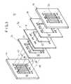
図1は、本発明の第1の実施形態に係る燃料電池スタック10の概略斜視説明図であり、図2は、前記燃料電池スタック10の要部断面説明図であり、図3は、前記燃料電池スタック10の一部分解斜視説明図である。
【0013】
燃料電池スタック10は、単位燃料電池セル12と、この単位燃料電池セル12を挟持する第1および第2セパレータ14、16とを備え、必要に応じてこれらが複数組だけ積層されている。単位燃料電池セル12は、固体高分子電解質膜18と、この電解質膜18を挟んで配設されるアノード側電極20およびカソード側電極22とを有する。
【0014】
図3に示すように、単位燃料電池セル12の両側には、第1および第2ガスケット24、26が設けられ、前記第1ガスケット24は、アノード側電極20を収納するための大きな開口部28を有する一方、前記第2ガスケット26は、カソード側電極22を収納するための大きな開口部30を有する。単位燃料電池セル12と第1および第2ガスケット24、26とが、第1および第2セパレータ14、16によって挟持され、これらが水平方向に複数組積層される。単位燃料電池セル12と第1および第2セパレータ14、16の積層方向両端部には、第1および第2エンドプレート32、34が配置され、タイロッド36を介して前記第1および第2エンドプレート32、34が一体的に締付け固定されている。
【0015】
燃料電池スタック10内には、上部側に燃料ガス供給流路38、酸化剤ガス供給流路40および冷却水排出流路42が一体的に形成されるとともに、下部側には、燃料ガス排出流路44、酸化剤ガス排出流路46および冷却水供給流路48が一体的に形成されている。
【0016】
第1セパレータ14のアノード側電極20に対向する面部には、燃料ガス供給流路38と燃料ガス排出流路44とを連通して上下方向に延在する第1流路50が形成される。第2セパレータ16のカソード側電極22に対向する面部には、酸化剤ガス供給流路40と酸化剤ガス排出流路46とを連通して上下方向に延在する第2流路52が形成される(図2参照)。第1および第2セパレータ14、16のそれぞれ他方の面部には、冷却水排出流路42と冷却水供給流路48とを連通して上下方向に延在する第3流路53が形成される。
【0017】
図1に示すように、第1エンドプレート32には、燃料ガス供給流路38に連結される第1供給配管54と、酸化剤ガス供給流路40に連結される第2供給配管56と、燃料ガス排出流路44に連結される第1排出配管58と、酸化剤ガス排出流路46に連結される第2排出配管60と、冷却水排出流路42に連結される冷却水排出配管62と、冷却水供給流路48に連結される冷却水供給配管64とが設けられる。
【0018】
図2に示すように、第1供給配管54は、図示しない燃料ガス供給源に連結される管路66を備え、この管路66の第1エンドプレート32の近傍に拡大部68が設けられる。拡大部68は、管路66よりも下方に突出する段差部位70を有しており、実際上、前記管路66の開口直径を拡径した円筒形状に設定されている。なお、第2供給配管56、第1排出配管58および第2排出配管60は、第1供給配管54と同様に構成されており、同一の構成要素には同一の参照符号を付してその詳細な説明は省略する。
【0019】
このように構成される燃料電池スタック10の動作について、以下に説明する。
【0020】
第1エンドプレート32に接続されている第1供給配管54から燃料ガス供給流路38に対し、予め水蒸気が含まれた水素ガス(燃料ガス)が供給されるとともに、第2供給配管56から酸化剤ガス供給流路40に対して水蒸気が含まれた酸化剤ガスである空気(または酸素ガス)が供給される。
【0021】
燃料ガス供給流路38に導入された水素ガスは、第1流路50に沿って下方向に移動しながら単位燃料電池セル12のアノード側電極20に供給される。一方、酸化剤ガス供給流路40に導入された空気は、同様に第2流路52に沿って下方向に移動しながら単位燃料電池セル12を構成するカソード側電極22に供給される。これにより、水素ガスは、水素イオン化されて電解質膜18を介してカソード側電極22側へと移動し、前記単位燃料電池セル12で発電が行われる。未使用の水素ガスは、燃料ガス排出流路44から第1排出配管58に送られるとともに、未使用の空気は、酸化剤ガス排出流路46から第2排出配管60に導出される。
【0022】
なお、冷却水供給流路48には、冷却水供給配管64から冷却水が供給されている。この冷却水は、第1および第2セパレータ14、16の第3流路53を流れることによって各単位燃料電池セル12を冷却した後、冷却水排出配管62に導出される。
【0023】
ところで、例えば、第1供給配管54には、予め電解質加湿用の水蒸気が含まれた水素ガスが供給されており、この第1供給配管54と燃料電池スタック10のスタック温度(冷却水温度)に温度差が生じると、前記第1供給配管54内で水蒸気の凝結が惹起される。そして、凝結した水は、水素ガスの流れに沿って燃料電池スタック10内に移動しようとする。
【0024】
この場合、第1の実施形態では、図2に示すように、第1供給配管54を構成する管路66が第1エンドプレート32の近傍に位置する拡大部68を設けており、この拡大部68には、前記管路66よりも下方に突出する段差部位70が形成されている。このため、第1供給配管54内で凝結した水72は、段差部位70に溜まって燃料電池スタック10内の燃料ガス供給流路38に流れることを防止することが可能になる。これにより、第1供給配管54内で凝結した水72が燃料電池スタック10内に入り込んで滞留することを確実に阻止し、各単位燃料電池セル12への水素ガスの均一分配を阻害することがない。
【0025】
一方、第1排出配管58内で凝結した水72も同様に、この第1排出配管58を構成する拡大部68内に貯留され、燃料電池スタック10内に逆流することを確実に阻止することができる。これによって、燃料電池スタック10内に不要な水72が導入されることがなく、この燃料電池スタック10を長時間にわたって安定して運転させることが可能になるという効果が得られる。
【0026】
また、空気の導入および導出を行う第2供給配管56および第2排出配管60においても同様に、凝結した水72が燃料電池スタック10内に導入されることがない。なお、第1の実施形態では、第1および第2供給配管54、56と第1および第2排出配管58、60とにそれぞれ拡大部68を設けているが、水蒸気の凝結が懸念されない部分にはこの拡大部68を設ける必要がなく、前記拡大部68を選択的に採用することができる。
【0027】
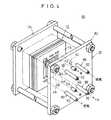
図4は、本発明の第2の実施形態に係る燃料電池スタック80の概略斜視説明図であり、図5は、前記燃料電池スタック80の要部断面説明図である。なお、第1の実施形態に係る燃料電池スタック10と同一の構成要素には、同一の参照符号を付してその詳細な説明は省略する。
【0028】
燃料電池スタック80を構成する第1エンドプレート82には、燃料ガス供給流路38に接続される第1供給配管84と、酸化剤ガス供給流路40に接続される第2供給配管86と、燃料ガス排出流路44に接続される第1排出配管88と、酸化剤ガス排出流路46に接続される第2排出配管90とが設けられる。第2の実施形態では、第1および第2供給配管84、86と第1および第2排出配管88、90のうち少なくとも1つに、燃料電池スタック80に向かって全体的に上方に傾斜する傾斜部92が設けられている。
【0029】
このように構成される第2の実施形態では、例えば、第1供給配管84内を流れる水素ガス中の水蒸気が凝結してこの第1供給配管84内に水が発生しても、燃料電池スタック80に向かって上方に傾斜する傾斜部92の勾配により、凝結した水が前記燃料電池スタック80内に移動することがない。一方、未使用の水素ガスが燃料電池スタック10から排出される第1排出配管88は、同様に傾斜部92を有している。従って、第1排出配管88内で凝結した水が燃料電池スタック80内に逆流することを確実に阻止することが可能になる。
【0030】
これにより、第2の実施形態では、簡単な構成で、燃料電池スタック80を長時間にわたって安定して運転させることができる等、第1の実施形態と同様の効果が得られる。
【0031】
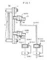
図6は、本発明の第3の実施形態に係る燃料電池スタック100の一部断面説明図である。なお、第1の実施形態に係る燃料電池スタック10と同一の構成要素には、同一の参照符号を付してその詳細な説明は省略する。
【0032】
燃料電池スタック100は、第1および第2供給配管54、56と、第1および第2排出配管58、60とを備えるとともに、それぞれ排水管102a〜102dを介して液溜り部104a〜104dに接続されている。液溜り部104a〜104dには、それぞれ貯留される水72の水位を検出する水位計106a〜106dと、前記水位計106a〜106dにより前記液溜り部104a〜104dに一定量以上の水72が貯留されていると判断された際、前記水72を排出するための排出弁108a〜108dとが設けられる。
【0033】
このように構成される第3の実施形態では、例えば、水素ガスを燃料電池スタック100内に供給するための第1供給配管54内で凝結した水72は、排水管102aを介して液溜り部104a内に貯留される。この液溜り部104aでは、水位計106aを介して水72の水位が計測され、この水位が一定量以上であると、排出弁108aが開かれて前記液溜り部104a内の水72が自動的に排出される。次いで、液溜り部104a内の水位が下限値に達すると、再び排出弁108aが閉じられて自動排水処理が終了する。
【0034】
このように、第3の実施形態では、第1供給配管54内で凝結した水が、一旦、液溜り部104aに貯留された後、排出弁108aを介して自動排水されている。従って、燃料電池スタック100内に不要な水72が導入されることを阻止するとともに、この燃料電池スタック100を一層長時間にわたって安定して連続運転し得るという利点がある。
【0035】
図7は、本発明の第4の実施形態に係る燃料電池スタック120の一部断面説明図である。なお、第3の実施形態に係る燃料電池スタック100と同一の構成要素には、同一の参照符号を付してその詳細な説明は省略する。
【0036】
この燃料電池スタック120では、第1および第2供給配管54、56と第1および第2排出配管58、60とが、燃料電池スタック120に向かって上方に傾斜する傾斜部122を設けている。従って、第4の実施形態では、段差部位70と傾斜部122とを介し、燃料電池スタック120内に水72が不要に導入されることを確実に阻止することができる他、第3の実施形態と同様の効果が得られる。
【0037】
【発明の効果】
本発明に係る燃料電池スタックでは、この燃料電池スタック内の燃料ガス流路および酸化剤ガス流路に連結される第1および第2供給配管と第1および第2排出配管のうち少なくとも1つが、配管自体の一部分に管路の他の部分よりも下方に突出する段差部位を有した拡大部を設けており、この管路内で凝結した水が前記段差部位に溜められるため、前記燃料電池スタック内に導入されることがない。これにより、簡単な構成で、燃料電池スタックを長時間にわたって安定して運転させることができる。
【0038】
また、本発明では、燃料電池スタックの燃料ガス流路および酸化剤ガス流路に連結される第1および第2供給配管と第1および第2排出配管のうち少なくとも1つが、前記燃料電池スタックに向かって上方に傾斜する傾斜部を設けている。このため、管路内で凝結した水が燃料電池スタック内に送り込まれたり、この燃料電池スタック内に逆流したりすることがなく、前記燃料電池スタックの発電性能を有効に維持することが可能になる。
【図面の簡単な説明】
【図1】本発明の第1の実施形態に係る燃料電池スタックの概略斜視説明図である。
【図2】前記燃料電池スタックの要部断面説明図である。
【図3】前記燃料電池スタックの一部分解斜視説明図である。
【図4】本発明の第2の実施形態に係る燃料電池スタックの概略斜視説明図である。
【図5】図4に示す前記燃料電池スタックの要部断面説明図である。
【図6】本発明の第3の実施形態に係る燃料電池スタックの一部断面説明図である。
【図7】本発明の第4の実施形態に係る燃料電池スタックの一部断面説明図である。
【符号の説明】
10、80、100、120…燃料電池スタック
12…単位燃料電池セル 14、16…セパレータ
18…電解質膜 20…アノード側電極
22…カソード側電極 24、26…ガスケット
32、34、82…エンドプレート 38…燃料ガス供給流路
40…酸化剤ガス供給流路 42…冷却水排出流路
44…燃料ガス排出流路 46…酸化剤ガス排出流路
48…冷却水供給流路 50、52、53…流路
54、56、84、86…供給配管 58、60、88、90…排出配管
62…冷却水排出配管 64…冷却水供給配管
68…拡大部 70…段差部位
92、122…傾斜部 104a〜104d…液留り部
106a〜106d…水位計 108a〜108d…排出弁[0001]
BACKGROUND OF THE INVENTION
The present invention relates to a fuel cell stack in which unit fuel cells and separators each having a solid polymer electrolyte membrane sandwiched between an anode electrode and a cathode electrode are alternately stacked.
[0002]
[Prior art]
In the polymer electrolyte fuel cell, a unit fuel cell in which an anode electrode and a cathode electrode are arranged on both sides of an electrolyte composed of a polymer ion exchange membrane (cation exchange membrane) is usually sandwiched between separators. The fuel cell stack is formed by stacking each other.
[0003]
In this type of fuel cell stack, a fuel gas, for example, hydrogen supplied to the anode side electrode is hydrogen ionized on the catalyst electrode and moves to the cathode side electrode side through an appropriately humidified electrolyte. Electrons generated in the meantime are taken out to an external circuit and used as direct current electric energy. Since the oxidant gas, for example, oxygen gas or air is supplied to the cathode side electrode, water reacts with the hydrogen ions, the electrons and oxygen to generate water.
[0004]
In this case, the electrolyte made of the polymer ion exchange membrane needs to be sufficiently humidified to maintain ion permeability. For this reason, in general, the oxidant gas and the fuel gas are humidified using a gas humidifier provided outside the fuel cell, and these are sent to the fuel cell stack as water vapor to humidify the electrolyte. It is configured as follows.
[0005]
[Problems to be solved by the invention]
By the way, since a solid polymer fuel cell has a relatively low operating temperature (up to 100 ° C.), before the moisture supplied to the oxidant gas or fuel gas for humidification is introduced into the fuel cell stack, piping is performed. There is a risk of condensation inside. On the other hand, moisture that has not been absorbed by the electrolyte after being introduced into the fuel cell stack or moisture generated by the reaction is cooled in the pipe after being discharged from the gas flow path in the fuel cell stack or the fuel cell stack, It tends to exist in the water state.
[0006]
However, as described above, if water is present in the piping near the fuel cell stack or in the gas flow path in the fuel cell stack, it is difficult to sufficiently supply the oxidant gas and fuel gas to each unit fuel cell. Become. Thereby, the problem that the diffusibility to the catalyst electrode layer of the fuel gas and oxidant gas which are reaction gas falls and the cell performance deteriorates remarkably is pointed out.
[0007]
The present invention solves this type of problem, and it is an object of the present invention to provide a fuel cell stack that can reliably prevent unnecessary water from being introduced into the fuel cell stack and can be simplified in configuration. And
[0008]
[Means for Solving the Problems]
In the fuel cell stack according to the present invention, the first and second supply pipes connected to the inlet side of the fuel gas channel and the oxidant gas channel in the fuel cell stack, the fuel gas channel and the oxidant The first and second exhaust pipes connected to the outlet side of the gas flow path, and at least one pipe has an enlarged portion having a stepped portion projecting downward from the other part in a part of thepipe itself. Provided.
[0009]
Here, the fuel cell stack is supplied with humidified gas having a dew point equal to or lower than the cooling water temperature (stack temperature) in order to prevent condensation. However, if there is a temperature difference between the pipe portion and the stack temperature, condensation of water vapor occurs in the pipe portion, and the condensed water may be introduced into the fuel cell stack. In that case, in this invention, the level difference part which protrudes below is formed in the enlarged part provided in the 1st supply piping or the 2nd supply piping, and the water condensed in the piping is stored in the level difference part. Therefore, it is possible to reliably prevent unnecessary water from being introduced into the gas flow path in the fuel cell stack.
[0010]
On the other hand, the water condensed in the piping communicating with the gas outlet side of the fuel cell stack may flow backward into the fuel cell stack. At this time, in the present invention, by providing the first discharge pipe and the second discharge pipe with the enlarged portion, the water in the pipe is stored in the stepped portion of the enlarged portion. It is possible to effectively prevent water from flowing backward.
[0011]
In the present invention, at least one of the first supply pipe, the second supply pipe, the first discharge pipe, and the second discharge pipe connected to the inlet and the outlet of the fuel gas channel and the oxidant gas channel is a fuel. An inclined portion that is inclined upward toward the battery stack is provided. For this reason, water condensed in the first supply pipe and the second supply pipe is not introduced into the fuel cell stack by the inclined portion, while water condensed in the first discharge pipe and the second discharge pipe. However, it can be reliably prevented from flowing back into the fuel cell stack.
[0012]
DETAILED DESCRIPTION OF THE INVENTION
FIG. 1 is a schematic perspective explanatory view of a
[0013]
The
[0014]
As shown in FIG. 3, first and
[0015]
In the
[0016]
A
[0017]
As shown in FIG. 1, the
[0018]
As shown in FIG. 2, the
[0019]
The operation of the
[0020]
Hydrogen gas (fuel gas) containing water vapor is supplied in advance from the
[0021]
The hydrogen gas introduced into the fuel
[0022]
The cooling
[0023]
By the way, for example, hydrogen gas containing water vapor for electrolyte humidification is supplied to the
[0024]
In this case, in the first embodiment, as shown in FIG. 2, the
[0025]
On the other hand, the
[0026]
Similarly, the
[0027]
FIG. 4 is a schematic perspective view of a
[0028]
The
[0029]
In the second embodiment configured as described above, for example, even when water vapor in the hydrogen gas flowing in the
[0030]
Thereby, in 2nd Embodiment, the effect similar to 1st Embodiment is acquired, such as being able to drive the
[0031]
FIG. 6 is a partial cross-sectional explanatory view of a
[0032]
The
[0033]
In the third embodiment configured as described above, for example, the
[0034]
Thus, in the third embodiment, the water condensed in the
[0035]
FIG. 7 is a partial cross-sectional explanatory view of a
[0036]
In the
[0037]
【The invention's effect】
In the fuel cell stack according to the present invention, at least one of the first and second supply pipes and the first and second discharge pipes connected to the fuel gas flow path and the oxidant gas flow path in the fuel cell stack,The fuel cell stack is provided with an enlarged portion having a stepped part protruding downward from the other part of the pipe line in a part of thepipe itself , and water condensed in the pipe line is accumulated in the stepped part. Will not be introduced in. As a result, the fuel cell stack can be stably operated for a long time with a simple configuration.
[0038]
In the present invention, at least one of the first and second supply pipes and the first and second discharge pipes connected to the fuel gas flow path and the oxidant gas flow path of the fuel cell stack is provided in the fuel cell stack. An inclined portion that is inclined upward is provided. For this reason, water condensed in the pipe line is not sent into the fuel cell stack and does not flow back into the fuel cell stack, and the power generation performance of the fuel cell stack can be effectively maintained. Become.
[Brief description of the drawings]
FIG. 1 is a schematic perspective view of a fuel cell stack according to a first embodiment of the present invention.
FIG. 2 is an explanatory cross-sectional view of a main part of the fuel cell stack.
FIG. 3 is a partially exploded perspective view of the fuel cell stack.
FIG. 4 is a schematic perspective explanatory view of a fuel cell stack according to a second embodiment of the present invention.
FIG. 5 is an explanatory cross-sectional view of a main part of the fuel cell stack shown in FIG. 4;
FIG. 6 is a partial cross-sectional explanatory view of a fuel cell stack according to a third embodiment of the present invention.
FIG. 7 is a partial cross-sectional explanatory view of a fuel cell stack according to a fourth embodiment of the present invention.
[Explanation of symbols]
DESCRIPTION OF
Claims (3)
Translated fromJapanese前記アノード側電極に燃料ガスを供給する燃料ガス流路と、前記カソード側電極に酸化剤ガスを供給する酸化剤ガス流路とが設けられた燃料電池スタックであって、
前記燃料電池スタックのエンドプレートに設けられ、前記燃料ガス流路および前記酸化剤ガス流路の入口側に連結される第1および第2供給配管と、
前記エンドプレートに設けられ、前記燃料ガス流路および前記酸化剤ガス流路の出口側に連結される第1および第2排出配管と、
を備え、
加湿された前記燃料ガスが供給される前記第1供給配管および加湿された前記酸化剤ガスが供給される前記第2供給配管のうち少なくとも1つは、配管自体の一部分に、該配管の開口直径を拡径することにより、他の部分よりも下方に突出する段差部位を有した拡大部を設け、該配管内で凝結した水が前記段差部位に排出されることを特徴とする燃料電池スタック。While laminating unit fuel cells and separators configured by sandwiching a polymer electrolyte membrane between an anode side electrode and a cathode side electrode alternately in the horizontal direction,
A fuel cell stack provided with a fuel gas flow path for supplying fuel gas to the anode side electrode and an oxidant gas flow path for supplying oxidant gas to the cathode side electrode,
First and second supply pipes provided on an end plate of the fuel cell stack and connected to inlet sides of the fuel gas flow path and the oxidant gas flow path;
First and second exhaust pipes provided on the end plate and connected to outlet sides of the fuel gas flow path and the oxidant gas flow path;
With
At least one of the first supply pipe to which the humidified fuel gas is supplied and the second supply pipe to which the humidified oxidant gas is supplied has anopening diameter of the pipe at a part ofthe pipe itself.by expanding the diameter of the enlarged portion having a step portion projecting downward than the other portions isprovided, the fuel cellstack water condense該配tract characterized Rukotois discharged to the step portion.
前記アノード側電極に燃料ガスを供給する燃料ガス流路と、前記カソード側電極に酸化剤ガスを供給する酸化剤ガス流路とが設けられた燃料電池スタックであって、
前記燃料電池スタックに前記水平方向に積層されたエンドプレートに設けられ、前記燃料ガス流路および前記酸化剤ガス流路の入口側に連結される第1および第2供給配管と、
前記エンドプレートに設けられ、前記燃料ガス流路および前記酸化剤ガス流路の出口側に連結される第1および第2排出配管と、
を備え、
加湿された前記燃料ガスが供給される前記第1供給配管および加湿された前記酸化剤ガスが供給される前記第2供給配管のうち少なくとも1つは、前記燃料電池スタックに向かって上方に傾斜する傾斜部を設け、配管内で凝結した水が前記燃料電池スタック内に移動することを阻止することを特徴とする燃料電池スタック。While laminating unit fuel cells and separators configured by sandwiching a polymer electrolyte membrane between an anode side electrode and a cathode side electrode alternately in the horizontal direction,
A fuel cell stack provided with a fuel gas flow path for supplying fuel gas to the anode side electrode and an oxidant gas flow path for supplying oxidant gas to the cathode side electrode,
A first supply pipe and a second supply pipe provided on an end plate stacked in the horizontal direction on the fuel cell stack and connected to an inlet side of the fuel gas flow path and the oxidant gas flow path;
First and second exhaust pipes provided on the end plate and connected to outlet sides of the fuel gas flow path and the oxidant gas flow path;
With
At least one of the first supply pipe to which the humidified fuel gas is supplied and the second supply pipe to which the humidified oxidant gas is supplied is inclined upward toward the fuel cell stack. an inclined portion isprovided, the fuel cellstack water condensed in the pipes, characterized thatyou prevented from moving into the fuel cell stack.
前記液溜まり部には、該液溜まり部に貯留される水の水位を検出する水位計と、
前記水位計により前記液溜まり部に一定量以上の水が貯留されたと判断された際、前記液溜まり部の水を排出するための排出弁と、
が設けられることを特徴とする燃料電池スタック。The fuel cell stack according to claim 1, wherein a liquid reservoir is provided that communicates with at least one of the first supply pipe and the second supply pipe;
In the liquid reservoir, a water level meter that detects the level of water stored in the liquid reservoir,
A discharge valve for discharging water from the liquid reservoir when it is determined by the water level gauge that a predetermined amount or more of water has been stored in the liquid reservoir;
A fuel cell stack.
Priority Applications (1)
| Application Number | Priority Date | Filing Date | Title |
|---|---|---|---|
| JP26184298AJP4456188B2 (en) | 1998-09-16 | 1998-09-16 | Fuel cell stack |
Applications Claiming Priority (1)
| Application Number | Priority Date | Filing Date | Title |
|---|---|---|---|
| JP26184298AJP4456188B2 (en) | 1998-09-16 | 1998-09-16 | Fuel cell stack |
Publications (3)
| Publication Number | Publication Date |
|---|---|
| JP2000090954A JP2000090954A (en) | 2000-03-31 |
| JP2000090954A5 JP2000090954A5 (en) | 2005-10-27 |
| JP4456188B2true JP4456188B2 (en) | 2010-04-28 |
Family
ID=17367513
Family Applications (1)
| Application Number | Title | Priority Date | Filing Date |
|---|---|---|---|
| JP26184298AExpired - LifetimeJP4456188B2 (en) | 1998-09-16 | 1998-09-16 | Fuel cell stack |
Country Status (1)
| Country | Link |
|---|---|
| JP (1) | JP4456188B2 (en) |
Families Citing this family (30)
| Publication number | Priority date | Publication date | Assignee | Title |
|---|---|---|---|---|
| CN1293661C (en)* | 2000-12-05 | 2007-01-03 | 松下电器产业株式会社 | Polymer electrolyte fuel cell and method of operation thereof |
| JP4967199B2 (en)* | 2001-05-15 | 2012-07-04 | トヨタ自動車株式会社 | Fuel cell piping structure |
| JP2005505116A (en) | 2001-09-27 | 2005-02-17 | シーメンス アクチエンゲゼルシヤフト | Fuel cell block |
| JP4672989B2 (en)* | 2004-03-03 | 2011-04-20 | 本田技研工業株式会社 | Fuel cell stack |
| DE112005000023B4 (en) | 2004-03-31 | 2010-08-12 | Toyota Jidosha Kabushiki Kaisha, Toyota-shi | fuel cell stack |
| JP4773081B2 (en)* | 2004-12-20 | 2011-09-14 | セイコーインスツル株式会社 | Fuel cell |
| JP4915044B2 (en)* | 2005-02-01 | 2012-04-11 | パナソニック株式会社 | Fuel cell system |
| JP4940567B2 (en)* | 2005-03-31 | 2012-05-30 | パナソニック株式会社 | Polymer electrolyte fuel cell system |
| JP4984543B2 (en)* | 2005-07-21 | 2012-07-25 | 日産自動車株式会社 | Fuel cell system |
| JP4939100B2 (en)* | 2006-04-18 | 2012-05-23 | 本田技研工業株式会社 | Fuel cell stack |
| JP2008103241A (en)* | 2006-10-20 | 2008-05-01 | Toyota Motor Corp | Fuel cell |
| JP4673877B2 (en)* | 2007-10-17 | 2011-04-20 | トヨタ自動車株式会社 | Fuel cell system |
| JP5368693B2 (en)* | 2007-11-19 | 2013-12-18 | 本田技研工業株式会社 | Short-circuit prevention structure for fuel cell system |
| JP5286780B2 (en)* | 2007-12-27 | 2013-09-11 | トヨタ自動車株式会社 | Fuel cell stack |
| EP2226877B1 (en) | 2007-12-28 | 2016-07-27 | Panasonic Intellectual Property Management Co., Ltd. | Fuel cell |
| JP5214298B2 (en)* | 2008-03-26 | 2013-06-19 | 本田技研工業株式会社 | Fuel cell system |
| JP5474318B2 (en)* | 2008-06-23 | 2014-04-16 | 本田技研工業株式会社 | Fuel cell stack |
| US9105915B2 (en) | 2009-01-26 | 2015-08-11 | Honda Motor Co., Ltd. | Fuel cell stack coupled to a humidifier via an inclined channel |
| JP5103411B2 (en)* | 2009-01-26 | 2012-12-19 | 本田技研工業株式会社 | Fuel cell stack |
| DE102010007977A1 (en) | 2010-02-15 | 2011-08-18 | Daimler AG, 70327 | Fuel cell system with at least one fuel cell |
| JP5404542B2 (en)* | 2010-07-08 | 2014-02-05 | 本田技研工業株式会社 | Fuel cell stack |
| JP5900045B2 (en)* | 2012-03-12 | 2016-04-06 | アイシン精機株式会社 | Oxidant gas supply pipe member and fuel cell system including the same |
| EP2919308B1 (en) | 2012-11-06 | 2016-10-19 | Panasonic Intellectual Property Management Co., Ltd. | Polyelectrolyte-type fuel cell |
| JP6059552B2 (en)* | 2013-02-18 | 2017-01-11 | 本田技研工業株式会社 | Fuel cell stack |
| CN103996868B (en) | 2013-02-18 | 2016-06-15 | 本田技研工业株式会社 | Fuel cell pack |
| JP6158527B2 (en)* | 2013-02-18 | 2017-07-05 | 本田技研工業株式会社 | Fuel cell stack |
| JP6180381B2 (en)* | 2014-07-16 | 2017-08-16 | 本田技研工業株式会社 | Fuel cell stack |
| JP6248889B2 (en)* | 2014-10-15 | 2017-12-20 | トヨタ紡織株式会社 | Oxidant gas discharge structure |
| KR101755891B1 (en) | 2015-11-20 | 2017-07-07 | 현대자동차주식회사 | Humidifier for fuel cell |
| KR102809757B1 (en)* | 2021-03-09 | 2025-05-20 | 코오롱인더스트리 주식회사 | Humidifier for fuel cell |
- 1998
- 1998-09-16JPJP26184298Apatent/JP4456188B2/ennot_activeExpired - Lifetime
Also Published As
| Publication number | Publication date |
|---|---|
| JP2000090954A (en) | 2000-03-31 |
Similar Documents
| Publication | Publication Date | Title |
|---|---|---|
| JP4456188B2 (en) | Fuel cell stack | |
| US7566511B2 (en) | Solid polymer cell assembly | |
| JP6660472B2 (en) | Humidifier with integrated water separator for fuel cell system, fuel cell system and vehicle with the same | |
| JP2001185172A (en) | Fuel cell and operating method thereof | |
| JP2010010073A (en) | Fuel cell stack | |
| JP2008103241A (en) | Fuel cell | |
| CA2403156C (en) | A fuel cell stack and a method of supplying reactant gases to the fuel cell stack | |
| KR20210004152A (en) | Humidifier for fuel cell | |
| JP2009064619A (en) | Fuel cell system | |
| JP4665353B2 (en) | Solid polymer electrolyte fuel cell power generator and its operation method | |
| JP5474318B2 (en) | Fuel cell stack | |
| JP2008243540A (en) | Solid polymer electrolyte fuel cell power generator | |
| RU2289177C2 (en) | Fuel cell | |
| CN100392902C (en) | A fuel cell that stabilizes the temperature and humidity of hydrogen or air entering the reaction | |
| CN100388543C (en) | A fuel cell with high operational stability | |
| JP5430318B2 (en) | Fuel cell stack | |
| JP5103411B2 (en) | Fuel cell stack | |
| KR20180080324A (en) | A fuel cell stack having a bipolar plate, | |
| JP2004206951A (en) | Fuel cell with dehumidifier | |
| JP3981476B2 (en) | Fuel cell stack | |
| JP5404542B2 (en) | Fuel cell stack | |
| JP3519987B2 (en) | Fuel cell stack | |
| JP2005228542A (en) | Fuel cell | |
| JP2004047154A (en) | Fuel cell reaction gas supply method | |
| JP4643968B2 (en) | Fuel cell system |
Legal Events
| Date | Code | Title | Description |
|---|---|---|---|
| A521 | Written amendment | Free format text:JAPANESE INTERMEDIATE CODE: A523 Effective date:20050707 | |
| A621 | Written request for application examination | Free format text:JAPANESE INTERMEDIATE CODE: A621 Effective date:20050707 | |
| A977 | Report on retrieval | Free format text:JAPANESE INTERMEDIATE CODE: A971007 Effective date:20080612 | |
| A131 | Notification of reasons for refusal | Free format text:JAPANESE INTERMEDIATE CODE: A131 Effective date:20090224 | |
| A521 | Written amendment | Free format text:JAPANESE INTERMEDIATE CODE: A523 Effective date:20090422 | |
| A02 | Decision of refusal | Free format text:JAPANESE INTERMEDIATE CODE: A02 Effective date:20090526 | |
| A521 | Written amendment | Free format text:JAPANESE INTERMEDIATE CODE: A523 Effective date:20090826 | |
| A911 | Transfer to examiner for re-examination before appeal (zenchi) | Free format text:JAPANESE INTERMEDIATE CODE: A911 Effective date:20091020 | |
| A131 | Notification of reasons for refusal | Free format text:JAPANESE INTERMEDIATE CODE: A131 Effective date:20100105 | |
| A521 | Written amendment | Free format text:JAPANESE INTERMEDIATE CODE: A523 Effective date:20100108 | |
| TRDD | Decision of grant or rejection written | ||
| A01 | Written decision to grant a patent or to grant a registration (utility model) | Free format text:JAPANESE INTERMEDIATE CODE: A01 Effective date:20100202 | |
| A01 | Written decision to grant a patent or to grant a registration (utility model) | Free format text:JAPANESE INTERMEDIATE CODE: A01 | |
| A61 | First payment of annual fees (during grant procedure) | Free format text:JAPANESE INTERMEDIATE CODE: A61 Effective date:20100205 | |
| FPAY | Renewal fee payment (event date is renewal date of database) | Free format text:PAYMENT UNTIL: 20130212 Year of fee payment:3 | |
| R150 | Certificate of patent or registration of utility model | Free format text:JAPANESE INTERMEDIATE CODE: R150 | |
| FPAY | Renewal fee payment (event date is renewal date of database) | Free format text:PAYMENT UNTIL: 20130212 Year of fee payment:3 | |
| FPAY | Renewal fee payment (event date is renewal date of database) | Free format text:PAYMENT UNTIL: 20140212 Year of fee payment:4 | |
| EXPY | Cancellation because of completion of term |