JP4455002B2 - High frequency knife - Google Patents
High frequency knifeDownload PDFInfo
- Publication number
- JP4455002B2 JP4455002B2JP2003347311AJP2003347311AJP4455002B2JP 4455002 B2JP4455002 B2JP 4455002B2JP 2003347311 AJP2003347311 AJP 2003347311AJP 2003347311 AJP2003347311 AJP 2003347311AJP 4455002 B2JP4455002 B2JP 4455002B2
- Authority
- JP
- Japan
- Prior art keywords
- electrode portion
- electrode
- knife
- frequency knife
- distal end
- Prior art date
- Legal status (The legal status is an assumption and is not a legal conclusion. Google has not performed a legal analysis and makes no representation as to the accuracy of the status listed.)
- Expired - Lifetime
Links
- 239000000615nonconductorSubstances0.000claimsdescription30
- 230000002093peripheral effectEffects0.000claimsdescription9
- 238000010292electrical insulationMethods0.000claimsdescription3
- 210000004877mucosaAnatomy0.000description23
- 210000001519tissueAnatomy0.000description20
- 230000000694effectsEffects0.000description17
- 230000003902lesionEffects0.000description9
- 230000005855radiationEffects0.000description8
- 238000011282treatmentMethods0.000description8
- 210000004400mucous membraneAnatomy0.000description7
- 238000000034methodMethods0.000description5
- 239000003989dielectric materialSubstances0.000description4
- 210000003811fingerAnatomy0.000description4
- 238000002271resectionMethods0.000description4
- 230000009471actionEffects0.000description3
- 229910001069Ti alloyInorganic materials0.000description2
- 229910010293ceramic materialInorganic materials0.000description2
- 239000004020conductorSubstances0.000description2
- 230000002496gastric effectEffects0.000description2
- 239000007924injectionSubstances0.000description2
- 238000002347injectionMethods0.000description2
- 238000003780insertionMethods0.000description2
- 230000037431insertionEffects0.000description2
- 239000000463materialSubstances0.000description2
- 230000008569processEffects0.000description2
- 238000000926separation methodMethods0.000description2
- 230000003416augmentationEffects0.000description1
- 230000008901benefitEffects0.000description1
- 230000008859changeEffects0.000description1
- 238000012277endoscopic treatmentMethods0.000description1
- 239000003779heat-resistant materialSubstances0.000description1
- 238000009413insulationMethods0.000description1
- 210000000936intestineAnatomy0.000description1
- 230000004048modificationEffects0.000description1
- 238000012986modificationMethods0.000description1
- 239000002504physiological saline solutionSubstances0.000description1
- 239000011347resinSubstances0.000description1
- 229920005989resinPolymers0.000description1
- 210000002784stomachAnatomy0.000description1
- BFKJFAAPBSQJPD-UHFFFAOYSA-NtetrafluoroetheneChemical groupFC(F)=C(F)FBFKJFAAPBSQJPD-UHFFFAOYSA-N0.000description1
- 210000003813thumbAnatomy0.000description1
Images


Classifications
- A—HUMAN NECESSITIES
- A61—MEDICAL OR VETERINARY SCIENCE; HYGIENE
- A61B—DIAGNOSIS; SURGERY; IDENTIFICATION
- A61B18/00—Surgical instruments, devices or methods for transferring non-mechanical forms of energy to or from the body
- A61B18/04—Surgical instruments, devices or methods for transferring non-mechanical forms of energy to or from the body by heating
- A61B18/12—Surgical instruments, devices or methods for transferring non-mechanical forms of energy to or from the body by heating by passing a current through the tissue to be heated, e.g. high-frequency current
- A61B18/14—Probes or electrodes therefor
- A61B18/1402—Probes for open surgery
- A—HUMAN NECESSITIES
- A61—MEDICAL OR VETERINARY SCIENCE; HYGIENE
- A61B—DIAGNOSIS; SURGERY; IDENTIFICATION
- A61B18/00—Surgical instruments, devices or methods for transferring non-mechanical forms of energy to or from the body
- A61B18/04—Surgical instruments, devices or methods for transferring non-mechanical forms of energy to or from the body by heating
- A61B18/12—Surgical instruments, devices or methods for transferring non-mechanical forms of energy to or from the body by heating by passing a current through the tissue to be heated, e.g. high-frequency current
- A61B18/14—Probes or electrodes therefor
- A61B18/1492—Probes or electrodes therefor having a flexible, catheter-like structure, e.g. for heart ablation
- A—HUMAN NECESSITIES
- A61—MEDICAL OR VETERINARY SCIENCE; HYGIENE
- A61B—DIAGNOSIS; SURGERY; IDENTIFICATION
- A61B17/00—Surgical instruments, devices or methods
- A61B17/32—Surgical cutting instruments
- A—HUMAN NECESSITIES
- A61—MEDICAL OR VETERINARY SCIENCE; HYGIENE
- A61B—DIAGNOSIS; SURGERY; IDENTIFICATION
- A61B18/00—Surgical instruments, devices or methods for transferring non-mechanical forms of energy to or from the body
- A61B2018/00571—Surgical instruments, devices or methods for transferring non-mechanical forms of energy to or from the body for achieving a particular surgical effect
- A61B2018/00601—Cutting
- A—HUMAN NECESSITIES
- A61—MEDICAL OR VETERINARY SCIENCE; HYGIENE
- A61B—DIAGNOSIS; SURGERY; IDENTIFICATION
- A61B18/00—Surgical instruments, devices or methods for transferring non-mechanical forms of energy to or from the body
- A61B18/04—Surgical instruments, devices or methods for transferring non-mechanical forms of energy to or from the body by heating
- A61B18/12—Surgical instruments, devices or methods for transferring non-mechanical forms of energy to or from the body by heating by passing a current through the tissue to be heated, e.g. high-frequency current
- A61B18/14—Probes or electrodes therefor
- A61B2018/1475—Electrodes retractable in or deployable from a housing
- Y—GENERAL TAGGING OF NEW TECHNOLOGICAL DEVELOPMENTS; GENERAL TAGGING OF CROSS-SECTIONAL TECHNOLOGIES SPANNING OVER SEVERAL SECTIONS OF THE IPC; TECHNICAL SUBJECTS COVERED BY FORMER USPC CROSS-REFERENCE ART COLLECTIONS [XRACs] AND DIGESTS
- Y10—TECHNICAL SUBJECTS COVERED BY FORMER USPC
- Y10T—TECHNICAL SUBJECTS COVERED BY FORMER US CLASSIFICATION
- Y10T83/00—Cutting
- Y10T83/04—Processes
Landscapes
- Health & Medical Sciences (AREA)
- Surgery (AREA)
- Life Sciences & Earth Sciences (AREA)
- Engineering & Computer Science (AREA)
- Molecular Biology (AREA)
- General Health & Medical Sciences (AREA)
- Veterinary Medicine (AREA)
- Public Health (AREA)
- Nuclear Medicine, Radiotherapy & Molecular Imaging (AREA)
- Biomedical Technology (AREA)
- Heart & Thoracic Surgery (AREA)
- Medical Informatics (AREA)
- Animal Behavior & Ethology (AREA)
- Physics & Mathematics (AREA)
- Plasma & Fusion (AREA)
- Otolaryngology (AREA)
- Cardiology (AREA)
- Surgical Instruments (AREA)
Description
Translated fromJapanese本発明は、例えば生体組織を切除するための高周波ナイフに関する。 The present invention relates to a high-frequency knife for excising living tissue, for example.
例えば経内視鏡的に粘膜等の生体組織を切除する処置は従来から行なわれている。このような切除処置を行なうには、例えば特許文献1に開示されているような高周波処置具が用いられている。 For example, a treatment for excising a living tissue such as a mucous membrane endoscopically has been conventionally performed. In order to perform such excision treatment, for example, a high-frequency treatment instrument as disclosed in
特許文献1に開示された高周波処置具は、軸方向に延びる針状のナイフ部(電極部)を有する。この針状のナイフ部に高周波電流を通電することにより、ナイフ部と接触する生体組織を焼灼切開することができる。
ところで、特許文献1に開示された高周波処置具を用いて生体組織を切除する場合、例えば前記ナイフ部を切除対象部位に穿刺して所定の切除方向に移動させる。このとき、術者は、切除対象部位の深部に位置する非切除組織とナイフ部とが接触しないように(非切除組織に電気的な作用を与えないように)、一定の深さでナイフ部を移動させる。そうすると、非切除組織を切除することなく、切除対象部位のみを切除することができる。しかし、このような操作はかなりの熟練を要するので、高周波ナイフを用いた切除処置を困難ならしめている。 By the way, when a living tissue is excised using the high-frequency treatment tool disclosed in
また、特許文献1に開示された高周波処置具は、電極としてのナイフ部が軸方向にだけ延在されているため、組織の切除方向が限定されてしまう。この結果、切除対象部位を容易に切除することができない場合もある。 Moreover, since the high frequency treatment tool disclosed by
本発明は、前記事情に着目してなされたものであり、その目的とするところは、切除方向の自由度を増やし、生体組織を容易に切除することが可能な高周波ナイフを提供することにある。 The present invention has been made paying attention to the above circumstances, and an object of the present invention is to provide a high-frequency knife capable of increasing the degree of freedom in the excision direction and easily excising living tissue. .
前記課題を解決するために、本発明に係る高周波ナイフは、少なくとも外周面に電気絶縁性を有する細長い筒状の本体部材と、軸状を有し、前記本体部材の内孔を軸方向に沿って移動して前記本体部材の先端に対して突没する第1の電極部と、前記第1の電極部の先端部に設けられ、前記第1の電極部の軸方向に対して少なくとも直交する方向に延びた複数の第2の電極部と、前記第1の電極部の先端部に設けられ、第1の電極部よりも大径の電気絶縁体とを具備し、前記第1および第2の電極部は、電気的に接続されていることを特徴とする。In order to solve the above problems, the high-frequency knifeaccording to the present invention includes an elongated tubular body member having an electrical insulating property at least on the outer peripheral surface has an axial, along the inner bore of the body member in the axial direction A first electrode portion projecting and sinking with respect to the tip end of the main body member, and a tip end portion of the first electrode portion, and at least orthogonal to the axial direction of the first electrode portion A plurality of second electrode portions extending in a direction, and an electric insulator provided at a tip portion of the first electrode portion and having a diameter larger than that of the first electrode portion. The electrode portions are electrically connected .
このような構成を有するので、電気絶縁体と第2の電極部との境界に生体組織を引っ掛けることによって、生体組織を処置することができる。また、軸状の第1の電極部によっても生体組織を処置することができる。このため、処置(切除)のための自由度が増し、生体組織を切除する操作をより容易にすることが可能である。With such a configuration, theliving tissue can be treated by hooking the living tissue on the boundary between the electrical insulator and the second electrode portion. Aliving tissue can also be treated with the first electrode portion having an axial shape. For this reason, the freedom degree for a treatment (resection) increases, and it is possible to make operation which resects abiological tissue easier.
本発明によれば、切除方向の自由度を増やし、生体組織を容易に切除することが可能な高周波ナイフを提供することができる。 ADVANTAGE OF THE INVENTION According to this invention, the high frequency knife which can increase the freedom degree of an excision direction and can excise a biological tissue easily can be provided.
以下、図面を参照しながらこの発明を実施するための最良の形態(以下、実施の形態という)について説明する。 The best mode for carrying out the present invention (hereinafter referred to as an embodiment) will be described below with reference to the drawings.
[第1の実施の形態]
まず、第1の実施の形態について図1ないし図6を用いて説明する。[First Embodiment]
First, a first embodiment will be described with reference to FIGS.
(構成)
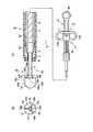
図1に示すように、この実施の形態に係わる高周波ナイフ1は、この高周波ナイフ1の本体部材としての円筒状のシース2と、このナイフ1の操作部3とを備えている。シース2は、内視鏡のチャンネル(図示せず)内を挿通可能な外径および可撓性を有する。シース2は、例えば密巻きコイル4と、絶縁チューブ5とを主に備えている。密巻きコイル4の外周は、絶縁チューブ5によって被覆されている。絶縁チューブ5は、例えばテトラフルオロエチレン材などの耐熱性や可撓性を有する樹脂材によって形成されている。絶縁チューブ5の外径は、内視鏡のチャンネル(図示せず)内を挿通可能な外径を有する。密巻きコイル4は、シース2が内視鏡のチャンネル(図示せず)内を挿通した状態で内視鏡の挿入部の形状変化に合わせて容易に形状を変化させることが可能な可撓性を有する。(Constitution)
As shown in FIG. 1, the high-
密巻きコイル4の先端には、筒状のストッパ部材6が連結されている。密巻きコイル4とストッパ部材6との連結部の内周面および外周面は、それぞれ互いに面一に形成されている。ストッパ部材6の先端部には、ストッパ部材6の先端部の肉厚を基端部よりも径方向内方側に厚くした肉厚部7が形成されている。この肉厚部7の先端側には、リング状のシース先端絶縁チップ8が配設されている。この絶縁チップ8は、セラミックス材など、耐熱性を有する材料で形成されていることが好ましい。この絶縁チップ8の内周面は、肉厚部7の内周面と略面一に形成されている。絶縁チップ8の外周面は、絶縁チューブ5に被覆されて保持されている。 A
この実施の形態に係わる高周波ナイフ1の操作部3は、シース2の基端部よりも術者の手元側に設けられている。操作部3は、操作部本体9と、操作部本体9に対してスライド可能な操作用スライダ10とを備えている。操作部本体9は、操作部本体9の先端部と基端部との間に直線状のガイド軸部9aが形成されている。操作用スライダ10は、操作部本体9の先端部と基端部との間のガイド軸部9aに沿って直線的にスライド可能である。操作部本体9は、指掛け用のリング9bを基端部に備えている。操作用スライダ10は、同様に指掛け用のリング10a,10bを操作部本体9の軸方向に対して直交する方向に備えている。このため、例えば操作部本体9のリング9bに親指を入れ、操作用スライダ10のリング10a,10bに人差指および中指を入れて、操作部本体9に対して操作用スライダ10をスライド操作可能である。操作用スライダ10は、高周波発生装置(図示せず)に通じる図示しないコードが電気的に接続される接続コネクタ部11を備えている。 The
シース2の内部には、導電性の操作ワイヤ12が挿通されている。この操作ワイヤ12の基端部は、操作用スライダ10の接続コネクタ部11に電気的に接続された状態で連結されている。すなわち、操作ワイヤ12は、操作用スライダ10に接続され、操作部本体9に対してスライド可能である。一方、操作ワイヤ12の先端部には、前述したストッパ部材6の肉厚部7に当接される導電性のストッパ受部13が装着されている。 A
このストッパ受部13には、ナイフ部14の基端部が接続されている。このナイフ部14は、電極15と、電気絶縁体部16とを備えている。電極15の基端部は、ストッパ受部13に接続されている。電極15の先端部には、電気絶縁体部16が設けられている。 A base end portion of the
電極15は、第1の電極部17と、第2の電極部18とを備えている。第1の電極部17は、例えば先端部から基端部にかけて径が一定の小径棒として形成されている。第1の電極部17は、シース2の先端からその軸方向に突出可能である。第2の電極部18は、第1の電極部17の先端部に設けられている。第2の電極部18は、第1の電極部17の軸方向に対して直交する方向に第1の電極部17から放射状に延びている。 The
第1の電極部17は、例えばチタン合金などの導電材料によって形成されている。この第1の電極部17の基端部は、ストッパ受部13に電気的に接続されている。したがって、第1の電極部17は、ストッパ受部13および操作ワイヤ12を介して、操作用スライダ10の接続コネクタ部11に電気的に接続されている。また、第1の電極部17は、操作ワイヤ12の進退動作により、シース2の内孔でシース2の軸方向に沿って移動し、シース2の先端に対して突没可能である。 The
第2の電極部18は、第1の電極部17の先端に一体的に形成されている。このため、第2の電極部18は、第1の電極部17と同様に、例えばチタン合金などの導電材料によって形成されている。図1(B)に示すように、第2の電極部18は、第1の電極部17の軸方向に対して放射状に三方向に延びている。すなわち、この実施の形態では、3つの第2の電極部18が設けられている。隣接する第2の電極部18同士は、第1の電極部17を中心として、それぞれ120°離れた位置に配設されている。なお、第1の電極部17から延出された第2の電極部18は、それぞれ例えば長方形状などの方形状を有する。 The
電気絶縁体部16は、例えばセラミック材などの耐熱性の電気絶縁体によって形成されている。図1(A)に示すように、電気絶縁体部16は、半球状の先端部16aと、この先端部16aと同じ外径を有する略円柱状(略円筒状)の基端部16bとを一体的に備えている。基端部16bの基端面16cには、第1の電極部17の先端部および第2の電極部18の先端部が電気絶縁体部16に保持(埋設)されて固定されている。このため、第2の電極部18は、電気絶縁体部16の基端部16bの基端面16cからシース2の先端部側に向かって突出されている。第1の電極部17は、基端部16bの中心軸上に固定されている。この実施の形態では、第1の電極部17に対して遠位端である第2の電極部18の放射端面18bと、第1の電極部17に対して第2の電極部18が固定された第2の電極部18の固定端18dとは、電気絶縁体部16の後述する基端面16cに対してそれぞれ同じ長さだけシース2の先端部側に突出されている。なお、電気絶縁体部16の基端部16bの外径は、第2の電極部18を保持した保持部(電気絶縁体部16の中心軸)から第2の電極部18の第1の電極部17に対する遠位端にかけての長さよりも大きく形成されている。 The
(作用)
次に、この実施の形態に係わる高周波ナイフ1の作用について説明する。まず、高周波ナイフ1の動作について説明する。
操作部3の操作用スライダ10と操作部本体9とを把持し、操作用スライダ10を操作部本体9に対して後方側(基端側)に移動させる。すると、操作ワイヤ12がシース2に対して後方側に移動する。このため、第1の電極部17がシース2の内部に引き込まれる。この結果、第2の電極部18の基端面18aは、シース2の先端の絶縁チップ8に当接される(図2参照)。これは、高周波ナイフ1を、例えば、内視鏡のチャンネルに挿入する場合など、ナイフ部14を使用しない状態である。(Function)
Next, the operation of the high-
The
一方、操作用スライダ10を操作部本体9に対して前方(先端側)に移動させる。すると、操作ワイヤ12は、操作用スライダ10とともにシース2に対して前方に移動する。このため、第1の電極部17がシース2の先端から外部に向けて突出するとともに、第2の電極部18の基端面18aがシース2の先端から前方側に離れる(図1および図3参照)。この状態は、高周波ナイフ1のナイフ部14に通電して粘膜切除する場合など、ナイフ部14を使用する状態である。なお、第1の電極部17(ナイフ部14)は、ストッパ受部13がシース2のストッパ部材6の肉厚部7に当接されるまで突出可能である。 On the other hand, the
次に、高周波ナイフ1を用いて例えば経内視鏡的に体腔内の粘膜切除を行なう際の動作について図4ないし図6を用いて説明する。
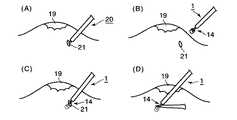
まず、図示しない内視鏡のチャンネルを通じて経内視鏡的に同じく図示しない注射針を体腔内に導入する。注射針を用いて、その体腔内における切除すべき目的部位である病変粘膜部分19の粘膜下層に生理食塩水を注入して、その病変粘膜部分19を隆起させる。Next, the operation when performing mucosal resection in a body cavity, for example, endoscopically using the
First, an injection needle (not shown) is introduced through the endoscope channel (not shown) into the body cavity. Using the injection needle, physiological saline is injected into the submucosal layer of the
次に、対極板(図示せず)を患者に装着する。その後、公知の針状の電極(ナイフ部)を有する高周波ナイフ20(例えば特許文献1参照)を同じく経内視鏡的に導入する。公知の針状の電極(ナイフ部)に通電して、病変粘膜部分19周囲の粘膜の一部に穴21を開ける初期切開を行なう(図4(A)参照)。そして、この高周波ナイフ20を内視鏡のチャンネルから引き抜いて抜去しておく。 Next, a counter electrode (not shown) is attached to the patient. Thereafter, a high-frequency knife 20 (see, for example, Patent Document 1) having a known needle-like electrode (knife portion) is also introduced endoscopically. A known needle-like electrode (knife part) is energized to make an initial incision in which a
続いて、図2に示すように、第1の電極部17をシース2内に引き込んだ状態である、この実施の形態に係わる高周波ナイフ1を、内視鏡の空いたチャンネルを介して体腔内に導入する。その高周波ナイフ1の先端部を内視鏡の挿入部の先端から突出させる(図4(B)参照)。そして、操作用スライダ9を操作部本体10に対してスライドさせて電気絶縁体部16をシース2の先端に対して離隔させる。初期切開した穴21の中に高周波ナイフ1のナイフ部14を先端部(電気絶縁体部16)から差し入れる(図4(C)参照)。 Subsequently, as shown in FIG. 2, the high-
この後、ナイフ部14の電極15(第1の電極部17および第2の電極部18)に高周波電流を供給しながら、高周波ナイフ1のナイフ部14を図4(D)に示すように所定の切除方向に沿って移動させる。例えばナイフ部14を横方向に動かすと、第1の電極部17に接触する粘膜が、第1の電極部17により切開される。 Thereafter, the high frequency current is supplied to the electrode 15 (the
ナイフ部14を横方向に動かし難い場合、図5に示すように、ナイフ部14全体を縦方向(第1の電極部17の軸方向)に動かす。すると、第2の電極部18(電気絶縁体部16)によって引っ掛け上げられる粘膜が第2の電極部18に接触することにより切開される。 When it is difficult to move the
この縦方向の動きと上述した横方向の動きとを組み合わせて高周波ナイフ1のナイフ部14を移動させる。そして、病変粘膜部分19の周りを病変粘膜部分19の周方向にわたって切開していく。 The
ナイフ部14の先端面(第2の電極部18の先端部)は、電気絶縁体部16によって覆われている。仮にナイフ部14の軸方向の移動(縦方向の動き)によってナイフ部14の先端が非切除組織22(図5参照)に接触しても、電気絶縁体部16の絶縁作用により、電極15に通電された高周波電流が非切除組織22へと流れることがない。このため、術者は、切除対象部位の深部に位置する非切除組織22とナイフ部14の高周波電流が流れる部位(電極15)とが接触しないように一定の深さでナイフ部14を移動させるといった煩雑な操作を行なう必要はない。 The distal end surface of the knife portion 14 (the distal end portion of the second electrode portion 18) is covered with an
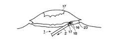
以上のようにして、病変粘膜部分19を周方向にわたって完全に切開したら、図6に示すように、病変粘膜部分19の周囲を切開した切り口23に第1の電極部17および第2の電極部18を当接させて、高周波ナイフ1の横方向および縦方向の動きを組み合わせて、第1の電極部17および第2の電極部18により病変粘膜部分19を順次切開して病変粘膜部分19剥離させていく。そして、病変粘膜部分19を全て切除して剥離させた後、高周波ナイフ1を図2に示す状態にして内視鏡のチャンネル内から手元側に引き抜く。内視鏡の空いたチャンネルに図示しない把持鉗子などを挿通させて把持鉗子を操作して経内視鏡的に病変粘膜部分19を取り出して処置を終了する。 When the
(効果)
以上説明したように、この実施の形態に係わる高周波ナイフ1は、電気絶縁性を有する本体部材としてのシース2と、シース2の先端からその軸方向に突没する第1の電極部17と、第1の電極部17の先端側に設けられ且つ第1の電極部17の軸方向に対して直交する方向に放射状に延びる複数の第2の電極部18と、第1および第2の電極部17,18の先端側に設けられ、少なくとも第1の電極部17よりも大径の電気絶縁体部16とを備えている。(effect)
As described above, the high-
したがって、病変粘膜部分19を切除するのに、ナイフ部14を横方向に移動させた場合だけでなく、第2の電極部18によって粘膜を引っ掛け上げるように軸方向を含む様々な方向にナイフ部14を移動させた場合にも組織の切開を行なうことができる。このため、切開可能な移動方向(切開方向の自由度)は、ナイフ部14に第1の電極部17だけが配置されている場合に比べて格段に増える。 Accordingly, not only when the
したがって、この実施の形態に係わる高周波ナイフ1を用いて病変粘膜部分19の切開操作を多岐にわたって容易に行なうことができる。 Therefore, the incision operation of the
また、この実施の形態に係わる高周波ナイフ1は、電極15の先端部に電気絶縁体部16を備えている。したがって、病変粘膜部分19を切開する際、術者は、切除対象部位の深部に位置する非切除組織22とナイフ部14の電極15とが接触しないように一定の軸方向範囲でナイフ部14を進退操作させるといった煩雑な操作を行なう必要がない。したがって、病変粘膜部分19の切開操作を容易に行なうことができる。 The high-
また、この実施の形態では、第2の電極部18が第1の電極部17に対して三方に延出されている。このため、病変粘膜部分19と第2の電極部18との接触面積が小さく、高周波電流の出力を集中させることができ、第2の電極部18の切れ味を向上させることができる。 In this embodiment, the
[第2の実施形態]
次に、第2の実施の形態について図7を用いて説明する。この実施の形態は第1の実施の形態の変形例であって、第1の実施の形態で説明した部材と同一の部材には同一の符号を付し、詳しい説明を省略する。以下、第3ないし第6の実施の形態についても同様である。[Second Embodiment]
Next, a second embodiment will be described with reference to FIG. This embodiment is a modification of the first embodiment. The same members as those described in the first embodiment are denoted by the same reference numerals, and detailed description thereof is omitted. The same applies to the third to sixth embodiments.
(構成)
図7に示すように、この実施の形態に係わる高周波ナイフ1におけるナイフ部14の第2の電極部18は、電気絶縁体部16の基端部16bの側面(略円柱状の外周面)とほぼ同じ位置まで第1の電極部17に対して直交する方向に延びている。例えば、第1の電極部17に対して遠位端である第2の電極部18の放射端面18bは、電気絶縁体部16の基端部16bの外周面と面一である。第1の実施の形態で説明したナイフ部14とはこの点のみ異なる。(Constitution)
As shown in FIG. 7, the
(作用)
この実施の形態に係わる高周波ナイフ1の作用については、第1の実施の形態で説明した高周波ナイフ1の作用と同一であるので説明を省略する。(Function)
Since the operation of the high-
(効果)
以上説明したように、この実施の形態によれば以下のことが言える。なお、第1の実施の形態で説明した高周波ナイフ1の効果と同一の効果については説明を省略する。(effect)
As described above, according to this embodiment, the following can be said. In addition, description is abbreviate | omitted about the effect same as the effect of the
ナイフ部14の第2の電極部18が電気絶縁体部16の側面とほぼ同じ位置まで延びているので、第2の電極部18で病変粘膜部分19の切開を行なう際、第1の実施の形態で説明した場合よりも大きく切開することができる。また、病変粘膜部分19を剥離させる際に、第2の電極部18の放射端面18bでより確実に切開を行なうことができる。 Since the
[第3の実施の形態]
次に、第3の実施の形態について図8(A)および図8(B)を用いて説明する。[Third Embodiment]
Next, a third embodiment will be described with reference to FIGS. 8A and 8B.
(構成)
図8(A)および図8(B)に示すように、この実施の形態に係わる高周波ナイフ1におけるナイフ部14の第2の電極部18は、その基端面18aが鋭利端18cとして形成されている。具体的には、第2の電極部18の断面は、略三角形状に形成され、第2の電極部18は、略三角柱状に形成されている。第2の実施の形態で説明したナイフ部14とはこの点のみ異なる。(Constitution)
As shown in FIGS. 8A and 8B, the
(作用)
この実施の形態に係わる高周波ナイフ1の作用については、第1の実施の形態で説明した高周波ナイフ1の作用と同一であるので説明を省略する。(Function)
Since the operation of the high-
(効果)
以上説明したように、この実施の形態によれば以下のことが言える。なお、第2の実施の形態で説明した高周波ナイフ1の効果と同一の効果については説明を省略する。(effect)
As described above, according to this embodiment, the following can be said. In addition, description is abbreviate | omitted about the effect same as the effect of the
第2の実施の形態で説明した第2の電極部18よりもその基端面18aが鋭利に形成されているので、第2の電極部18に接触する組織の切れ味を向上させることができる。 Since the
[第4の実施の形態]
次に、第4の実施の形態について図9(A)および図9(B)を用いて説明する。[Fourth Embodiment]
Next, a fourth embodiment will be described with reference to FIGS. 9A and 9B.
(構成)
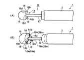
図9(A)および図9(B)に示すように、この実施の形態に係わる高周波ナイフ1におけるナイフ部14の第2の電極部18は、第1の電極部17の軸方向に対して直交する三方に放射状に延びた翼状の翼状部24として形成されている。第2の電極部18の放射端面18bは、第1の電極部17側の固定端18dより短く形成されている。このため、基端面(図3における基端面18aに対応)は、放射端面18bと固定端18dとにより、傾斜面18eが形成されている。第2の実施の形態で説明したナイフ部14とはこの点のみ異なる。(Constitution)
As shown in FIGS. 9A and 9B, the
(作用)
次に、この実施の形態に係わる高周波ナイフ1の作用について説明する。なお、第1の実施の形態で説明した高周波ナイフ1の作用と同一の作用については説明を省略する。(Function)
Next, the operation of the high-
第2の電極部18に病変粘膜部分19を当接させて切開・剥離する際、横方向および縦方向(軸方向)の他に両者の中間方向に斜めに引いても切開・剥離を行なうことができる。 When the lesioned
(効果)
以上説明したように、この実施の形態によれば以下のことが言える。なお、上述した実施の形態で説明した高周波ナイフ1の効果と同一の効果については説明を省略する。(effect)
As described above, according to this embodiment, the following can be said. In addition, description is abbreviate | omitted about the effect same as the effect of the
ナイフ部14の第2の電極部18が、翼状部24として形成され、基端面が、傾斜面18eとして形成されているので、病変粘膜部分19の切開・剥離の際、横方向、軸方向のほか、中間の斜め後方に引いて切開・剥離を行なうことができる。このため、手技の効率が向上する。 Since the
[第5の実施の形態]
次に、第5の実施の形態について図10(A)および図10(B)を用いて説明する。[Fifth Embodiment]
Next, a fifth embodiment will be described with reference to FIGS. 10 (A) and 10 (B).
(構成)
図10(A)および図10(B)に示すように、この実施の形態に係わる高周波ナイフ1におけるナイフ部14の第2の電極部18は、放射端面18bが、第1の電極部17側の固定端18dより長く形成されている。これにより基端面18aは、中心方向に向かって傾斜する傾斜面18eとして形成されている。第2の実施の形態で説明したナイフ部14とはこの点のみ異なる。(Constitution)
As shown in FIGS. 10A and 10B, the
(作用)
この実施の形態に係わる高周波ナイフ1の作用については、第1の実施の形態で説明した高周波ナイフ1の作用と同一であるので説明を省略する。(Function)
Since the operation of the high-
(効果)
以上説明したように、この実施の形態によれば以下のことが言える。なお、第2の実施の形態で説明した高周波ナイフ1と同一の効果については説明を省略する。(effect)
As described above, according to this embodiment, the following can be said. In addition, description is abbreviate | omitted about the effect same as the
第2の電極部18の基端面18aが、中心に向かって傾斜する傾斜面18eが形成されているので、病変粘膜部分19を第2の電極部18で切開・剥離する際の引っ掛かりが十分得られる。 Since the
[第6の実施の形態]
次に、第6の実施の形態について図11(A)および図11(B)を用いて説明する。[Sixth Embodiment]
Next, a sixth embodiment will be described with reference to FIGS. 11A and 11B.
(構成)
図11(A)および図11(B)に示すように、この実施の形態に係わる高周波ナイフ1におけるナイフ部14の第2の電極部18は、第1の電極部17の軸方向に対して直交する三方に放射状に延びた棒状の棒状部25として形成されている。また、第2の電極部18は、電気絶縁体部16の基端面16cからやや間隔26をおいた位置に設けられている。第2の実施の形態で説明したナイフ部14とはこの点のみ異なる。(Constitution)
As shown in FIG. 11A and FIG. 11B, the
(作用)
この実施の形態に係わる高周波ナイフ1の作用については、第1の実施の形態で説明した高周波ナイフ1の作用と同一であるので説明を省略する。(Function)
Since the operation of the high-
(効果)
以上説明したように、この実施の形態によれば以下のことが言える。なお、第2の実施の形態で説明した高周波ナイフ1の効果と同一の効果については説明を省略する。(effect)
As described above, according to this embodiment, the following can be said. In addition, description is abbreviate | omitted about the effect same as the effect of the
第2の電極部18が棒状部25として形成されている。また、第2の電極部18(棒状部25)は、電気絶縁体部16の基端面16cから間隔26をおいて離れた位置に設けられている。このため、病変粘膜部分19と第2の電極部18との間の接触面積が小さく、高周波電流の出力を集中させることができ、第2の電極部18の切れ味を向上させることができる。 The
なお、第1ないし第6の実施の形態では、第2の電極部18の数を三方(3つ)として説明したが、三方に限ることはなく、例えば四方(4つ)や五方(5つ)などであっても良い。このとき、隣接する第2の電極部18間は、第1の電極部17に対して同じ角度をもって配設されていることが好ましい。 In the first to sixth embodiments, the number of the
また、第1ないし第6の実施の形態で説明した第2の電極部18の形状は、同一のナイフ部14には、同一の形状を有するものに限ることはなく、適宜に組み合わせても良い。例えば、第1の実施の形態で説明した第2の電極部18(図3参照)と、第2の実施の形態で説明した第2の電極部18(図7参照)と、第3の実施の形態で説明した第2の電極部18(図8(A)参照)との3つの第2の電極部18を適宜に組み合わせても良い。 The shape of the
これまで、いくつかの実施の形態について図面を参照しながら具体的に説明したが、この発明は、上述した実施の形態に限定されるものではなく、その要旨を逸脱しない範囲で行なわれるすべての実施を含む。 Although several embodiments have been specifically described so far with reference to the drawings, the present invention is not limited to the above-described embodiments, and all the embodiments performed without departing from the scope of the invention are described. Including implementation.
以上説明してきた技術内容によれば、以下に示されるような各種の構成が得られる。なお、各項の組み合わせも可能である。 According to the technical contents described above, various configurations as shown below can be obtained. Combinations of each item are also possible.
[付記]
(付記項1) 電気絶縁性を有する本体部材と、
前記本体部材の先端からその軸方向に突没する第1の電極部と、
前記第1の電極部の先端側に配設され、前記第1の電極部の軸方向に対して直交する方向に放射状に延びる複数の第2の電極部と、
前記第1および第2の電極部の先端側に設けられ、少なくとも第1の電極部よりも大径の電気絶縁体と、
を備えていることを特徴とする高周波ナイフ。[Appendix]
(Additional Item 1) A body member having electrical insulation,
A first electrode portion projecting in the axial direction from the tip of the body member;
A plurality of second electrode portions disposed on the distal end side of the first electrode portion and extending radially in a direction orthogonal to the axial direction of the first electrode portion;
An electrical insulator which is provided on the distal end side of the first and second electrode portions and has a diameter larger than at least the first electrode portion;
A high-frequency knife characterized by comprising:
(付記項2) 前記電気絶縁体は、前記第2の電極部と同径もしくはそれより大径であることを特徴とする付記項1に記載の高周波ナイフ。 (Additional Item 2) The high-frequency knife according to
(付記項3) 前記第2の電極部は、三方に延びることを特徴とする付記項1に記載の高周波ナイフ。 (Additional Item 3) The high frequency knife according to
(付記項4) 前記第2の電極部は、前記電気絶縁体の基端側端面に接触して設けられていることを特徴とする付記項1に記載の高周波ナイフ。 (Additional Item 4) The high-frequency knife according to
(付記項5) 前記第2の電極部は、前記電気絶縁体の基端側端面から間隔をおいて離れて設けられていることを特徴とする付記項1に記載の高周波ナイフ。 (Additional Item 5) The high frequency knife according to
(付記項6) 前記第2の電極部は、前記本体部材側端部が鋭利に形成されていることを特徴とする付記項1に記載の高周波ナイフ。 (Additional Item 6) The high-frequency knife according to
(付記項7) 前記第2の電極部は、前記第1の電極部の軸方向に対して直交する方向に向かって傾斜していることを特徴とする付記項1に記載の高周波ナイフ。 (Additional Item 7) The high frequency knife according to
(付記項8) 前記傾斜は、前記第2の電極部の放射端側が前記第1の電極部側より長手方向に長いことで形成されることを特徴とする付記項7に記載の高周波ナイフ。 (Additional Item 8) The high-frequency knife according to
(付記項9) 前記傾斜は、前記第2の電極部の放射端側が前記第1の電極部側より長手方向に短いことで形成されることを特徴とする付記項7に記載の高周波ナイフ。 (Additional Item 9) The high-frequency knife according to
(付記項10) 前記第2の電極部は、隣接する第2の電極部に対して所定の角度に配設されていることを特徴とする付記項1に記載の高周波ナイフ。 (Additional Item 10) The high frequency knife according to
(付記項11) チャンネルを有する内視鏡と、
絶縁性を有するとともに前記チャンネル内を挿通可能な筒状の本体部材と、
前記本体部材に内挿され、前記本体部材の先端に対して突没可能な軸状の電気導電性部材と、
前記電気導電性部材の基端部に設けられ、術者により前記本体部材に対して電気導電性部材を突没させる操作部と、
前記電気導電性部材の先端部に設けられ、前記第1の電極部の軸方向に対して直交する方向に延びた第2の電極部と、
前記第2の電極部の先端側に設けられ、前記第1の電極部よりも大径の電気絶縁性部材と
を具備することを特徴とする内視鏡装置。(Additional Item 11) An endoscope having a channel;
A cylindrical main body member that has insulation and can be inserted through the channel;
A shaft-shaped electrically conductive member that is inserted into the body member and can project and retract with respect to the tip of the body member;
An operation portion provided at a base end portion of the electrically conductive member, and projecting and retracting the electrically conductive member with respect to the main body member by an operator;
A second electrode portion provided at a tip portion of the electrically conductive member and extending in a direction orthogonal to the axial direction of the first electrode portion;
An endoscope apparatus comprising: an electrical insulating member provided on a distal end side of the second electrode portion and having a larger diameter than the first electrode portion.
1…高周波ナイフ、2…シース(本体部材)、3…操作部、12…操作ワイヤ、14…ナイフ部、15…電極、16…電気絶縁体、17…第1の電極部、18…第2の電極部 DESCRIPTION OF
Claims (6)
Translated fromJapanese軸状を有し、前記本体部材の内孔を軸方向に沿って移動して前記本体部材の先端に対して突没する第1の電極部と、
前記第1の電極部の先端部に設けられ、前記第1の電極部の軸方向に対して少なくとも直交する方向に延びた複数の第2の電極部と、
前記第1の電極部の先端部に設けられ、第1の電極部よりも大径の電気絶縁体と
を具備し、
前記第1および第2の電極部は、電気的に接続されていることを特徴とする高周波ナイフ。An elongated cylindrical body member having electrical insulation on at least the outer peripheral surface;
A first electrode portion having an axial shape, moving along an axial direction of the body member along the axial direction, and projecting and retracting with respect to a tip of the body member;
A plurality of second electrode portions provided at a distal end portion of the first electrode portion and extending in a direction at least orthogonal to the axial direction of the first electrode portion;
An electrical insulator provided at the tip of the first electrode part and having a larger diameter than the first electrode part;
The high frequency knife according to claim 1, wherein the first and second electrode portions are electrically connected.
Priority Applications (6)
| Application Number | Priority Date | Filing Date | Title |
|---|---|---|---|
| JP2003347311AJP4455002B2 (en) | 2003-10-06 | 2003-10-06 | High frequency knife |
| KR1020040078889AKR100595803B1 (en) | 2003-10-06 | 2004-10-05 | High-frequency knife and endoscopic apparatus |
| EP20040023792EP1522269B1 (en) | 2003-10-06 | 2004-10-06 | High-frequency knife and endoscopic apparatus |
| US10/959,642US7618416B2 (en) | 2003-10-06 | 2004-10-06 | High-frequency knife, endoscopic apparatus, and method of resecting lesioned mucosal part using high-frequency knife |
| DE200460030308DE602004030308D1 (en) | 2003-10-06 | 2004-10-06 | HF-meter and endoscopy device |
| CNB200410080738XACN100333698C (en) | 2003-10-06 | 2004-10-08 | High-frequency knife and endoscopic apparatus |
Applications Claiming Priority (1)
| Application Number | Priority Date | Filing Date | Title |
|---|---|---|---|
| JP2003347311AJP4455002B2 (en) | 2003-10-06 | 2003-10-06 | High frequency knife |
Publications (2)
| Publication Number | Publication Date |
|---|---|
| JP2005110861A JP2005110861A (en) | 2005-04-28 |
| JP4455002B2true JP4455002B2 (en) | 2010-04-21 |
Family
ID=34309187
Family Applications (1)
| Application Number | Title | Priority Date | Filing Date |
|---|---|---|---|
| JP2003347311AExpired - LifetimeJP4455002B2 (en) | 2003-10-06 | 2003-10-06 | High frequency knife |
Country Status (6)
| Country | Link |
|---|---|
| US (1) | US7618416B2 (en) |
| EP (1) | EP1522269B1 (en) |
| JP (1) | JP4455002B2 (en) |
| KR (1) | KR100595803B1 (en) |
| CN (1) | CN100333698C (en) |
| DE (1) | DE602004030308D1 (en) |
Cited By (2)
| Publication number | Priority date | Publication date | Assignee | Title |
|---|---|---|---|---|
| WO2014038547A1 (en) | 2012-09-10 | 2014-03-13 | オリンパスメディカルシステムズ株式会社 | Endoscopic treatment tool |
| WO2014042039A1 (en) | 2012-09-12 | 2014-03-20 | オリンパスメディカルシステムズ株式会社 | High frequency knife |
Families Citing this family (44)
| Publication number | Priority date | Publication date | Assignee | Title |
|---|---|---|---|---|
| EP1726267B1 (en)* | 2005-05-25 | 2008-08-06 | Fujinon Corporation | High frequency treatment tool |
| JP4836492B2 (en)* | 2005-05-25 | 2011-12-14 | 富士フイルム株式会社 | High-frequency treatment instrument and mucosal detachment method using the high-frequency treatment instrument |
| JP4756951B2 (en)* | 2005-08-10 | 2011-08-24 | オリンパスメディカルシステムズ株式会社 | Monopolar high frequency treatment device |
| US8372071B2 (en) | 2005-08-12 | 2013-02-12 | Fujinon Corporation | High-frequency treatment tool |
| KR100777992B1 (en)* | 2005-08-12 | 2007-11-29 | 후지논 가부시키가이샤 | High frequency aid |
| US20070255278A1 (en)* | 2006-04-28 | 2007-11-01 | Nobis Rudolph H | Apparatus and method for deploying a cutting element during an endoscopic mucosal resection |
| US7867228B2 (en)* | 2006-04-28 | 2011-01-11 | Ethicon Endo-Surgery, Inc. | Apparatus and method for performing an endoscopic mucosal resection |
| US7651491B2 (en)* | 2006-04-28 | 2010-01-26 | Ethicon Endo-Surgery, Inc. | Method for performing an endoscopic mucosal resection |
| JP4616210B2 (en) | 2006-06-01 | 2011-01-19 | オリンパスメディカルシステムズ株式会社 | High frequency treatment tool |
| EP2049034B1 (en) | 2006-07-20 | 2012-01-11 | Boston Scientific Limited | Multifunction medical device and related methods of use |
| JP4600683B2 (en)* | 2006-07-31 | 2010-12-15 | 富士フイルム株式会社 | High frequency treatment tool |
| US20080243121A1 (en)* | 2007-04-02 | 2008-10-02 | Tomoyuki Takashino | Curative treatment system, curative treatment device, and treatment method for living tissue using energy |
| US20080243213A1 (en)* | 2007-04-02 | 2008-10-02 | Tomoyuki Takashino | Curative treatment system, curative treatment device, and treatment method for living tissue using energy |
| JP2009112788A (en)* | 2007-10-17 | 2009-05-28 | Takashi Toyonaga | High frequency tool |
| JP4725807B2 (en)* | 2007-11-12 | 2011-07-13 | 有限会社リバー精工 | High frequency knife for endoscopic mucosal resection and manufacturing method thereof |
| KR100949996B1 (en)* | 2008-02-28 | 2010-03-26 | (주)트리플씨메디칼 | Radiofrequency Medical Cautery and Radiofrequency Therapy |
| JP4870710B2 (en)* | 2008-03-28 | 2012-02-08 | 富士フイルム株式会社 | High frequency knife and high frequency knife system |
| JP5415727B2 (en)* | 2008-08-13 | 2014-02-12 | オリンパスメディカルシステムズ株式会社 | Endoscopic treatment tool |
| JP2010046199A (en)* | 2008-08-20 | 2010-03-04 | Fujinon Corp | High frequency treatment tool |
| ATE507791T1 (en)* | 2008-09-30 | 2011-05-15 | Univ Jichi Medical | TREATMENT INSTRUMENT FOR ENDOSCOPES |
| DE102009017636A1 (en)* | 2009-04-16 | 2010-10-21 | Erbe Elektromedizin Gmbh | Endoscopic surgical instrument |
| KR101356607B1 (en)* | 2012-06-26 | 2014-02-03 | 신경민 | High-frequency treatment device |
| EP2910212A4 (en)* | 2012-10-17 | 2016-06-22 | Olympus Corp | High frequency knife |
| CN102940527B (en)* | 2012-11-19 | 2015-01-21 | 北京大学第三医院 | Radio-frequency knife for electrosurgical operation |
| EP3049009A1 (en)* | 2013-09-27 | 2016-08-03 | Cook Medical Technologies LLC | Dome-shaped bipolar electrode assembly |
| WO2015133442A1 (en)* | 2014-03-04 | 2015-09-11 | オリンパス株式会社 | Treatment instrument for endoscope |
| JP6463128B2 (en)* | 2014-12-26 | 2019-01-30 | オリンパス株式会社 | Connection structure and connection method |
| KR101685009B1 (en) | 2015-02-27 | 2016-12-09 | 연세대학교 원주산학협력단 | Cutting device and endoscope comprising the same |
| JP6084350B1 (en)* | 2015-06-18 | 2017-02-22 | オリンパス株式会社 | High frequency treatment tool |
| US11504104B2 (en) | 2015-10-20 | 2022-11-22 | Lumendi Ltd. | Medical instruments for performing minimally-invasive procedures |
| US11446081B2 (en) | 2015-10-20 | 2022-09-20 | Lumedi Ltd. | Medical instruments for performing minimally-invasive procedures |
| JP6938488B2 (en) | 2015-10-20 | 2021-09-22 | ルメンディ リミテッド | Medical equipment for minimally invasive procedures |
| KR102026938B1 (en) | 2017-06-13 | 2019-09-30 | 주식회사 파인메딕스 | Hybrid knife for endoscope |
| CN110831532B (en)* | 2017-06-29 | 2023-03-21 | 朝日英达科株式会社 | Guide wire for plasma |
| KR20190020601A (en) | 2017-12-01 | 2019-03-04 | 유펙스메드 주식회사 | High frequency knife for endoscopic submucosal dissection with multiple tips |
| CN108272503B (en) | 2018-03-07 | 2024-04-19 | 南微医学科技股份有限公司 | Double-channel liquid injection bipolar high-frequency electric knife |
| CN108784828B (en)* | 2018-07-04 | 2024-04-19 | 北京安和加利尔科技有限公司 | High-frequency electrotome with double tool bits for endoscope |
| WO2020195210A1 (en)* | 2019-03-22 | 2020-10-01 | 株式会社カネカ | Endoscopic treatment instrument |
| WO2021124384A1 (en)* | 2019-12-16 | 2021-06-24 | オリンパス株式会社 | High-frequency surgical instrument and method for operating high-frequency surgical instrument |
| KR20210115644A (en)* | 2020-03-16 | 2021-09-27 | 유펙스메드 주식회사 | A medical dispensing mechanism capable of combining two kinds of treatment tools having an independent driving range |
| CN112370148B (en)* | 2020-11-14 | 2022-04-08 | 重庆金山医疗技术研究院有限公司 | Argon electrode ceramic body, circular spraying type argon electrode and manufacturing method thereof |
| CN112370149B (en)* | 2020-11-14 | 2022-04-08 | 重庆金山医疗技术研究院有限公司 | Ceramic body, circular spraying type argon electrode and manufacturing method thereof |
| WO2022182981A1 (en) | 2021-02-25 | 2022-09-01 | Lumendi LLC | Medical instruments for performing minimally-invasive procedures |
| KR102624728B1 (en)* | 2021-08-27 | 2024-01-11 | 연세대학교 원주산학협력단 | Tissue removal apparatus |
Family Cites Families (16)
| Publication number | Priority date | Publication date | Assignee | Title |
|---|---|---|---|---|
| US4493320A (en)* | 1982-04-02 | 1985-01-15 | Treat Michael R | Bipolar electrocautery surgical snare |
| JPS62211060A (en)* | 1986-03-12 | 1987-09-17 | オリンパス光学工業株式会社 | High frequency treatment tool |
| US5069679A (en)* | 1989-02-16 | 1991-12-03 | Taheri Syde A | Method and apparatus for removing venous valves |
| US4976711A (en)* | 1989-04-13 | 1990-12-11 | Everest Medical Corporation | Ablation catheter with selectively deployable electrodes |
| US5078716A (en)* | 1990-05-11 | 1992-01-07 | Doll Larry F | Electrosurgical apparatus for resecting abnormal protruding growth |
| US5171255A (en)* | 1990-11-21 | 1992-12-15 | Everest Medical Corporation | Biopsy device |
| JPH04329944A (en) | 1991-01-25 | 1992-11-18 | Olympus Optical Co Ltd | High-frequency incision apparatus |
| US5197964A (en)* | 1991-11-12 | 1993-03-30 | Everest Medical Corporation | Bipolar instrument utilizing one stationary electrode and one movable electrode |
| CN2176123Y (en)* | 1993-05-24 | 1994-09-07 | 西安市三兴科技实业公司 | Radiofrequency cardiac catheter |
| JP3655664B2 (en) | 1995-05-02 | 2005-06-02 | オリンパス株式会社 | High frequency knife |
| US5846241A (en)* | 1995-12-19 | 1998-12-08 | Johns Hopkins University | Bipolar electrocautery valvulotome |
| US5916213A (en)* | 1997-02-04 | 1999-06-29 | Medtronic, Inc. | Systems and methods for tissue mapping and ablation |
| ATE433306T1 (en)* | 1997-07-08 | 2009-06-15 | Univ California | DEVICE FOR CIRCUMFERENTIAL ABLATION |
| US5961526A (en)* | 1998-02-18 | 1999-10-05 | Boston Scientific Corporation | Coaxial needle and severing snare |
| US6511492B1 (en)* | 1998-05-01 | 2003-01-28 | Microvention, Inc. | Embolectomy catheters and methods for treating stroke and other small vessel thromboembolic disorders |
| US6468227B2 (en)* | 2000-03-17 | 2002-10-22 | Zimmon Science Corporation | Device for performing a medical procedure |
- 2003
- 2003-10-06JPJP2003347311Apatent/JP4455002B2/ennot_activeExpired - Lifetime
- 2004
- 2004-10-05KRKR1020040078889Apatent/KR100595803B1/ennot_activeExpired - Fee Related
- 2004-10-06USUS10/959,642patent/US7618416B2/enactiveActive
- 2004-10-06DEDE200460030308patent/DE602004030308D1/ennot_activeExpired - Lifetime
- 2004-10-06EPEP20040023792patent/EP1522269B1/ennot_activeExpired - Lifetime
- 2004-10-08CNCNB200410080738XApatent/CN100333698C/ennot_activeExpired - Lifetime
Cited By (5)
| Publication number | Priority date | Publication date | Assignee | Title |
|---|---|---|---|---|
| WO2014038547A1 (en) | 2012-09-10 | 2014-03-13 | オリンパスメディカルシステムズ株式会社 | Endoscopic treatment tool |
| US9237918B2 (en) | 2012-09-10 | 2016-01-19 | Olympus Corporation | Endoscope treatment tool |
| EP2893895A4 (en)* | 2012-09-10 | 2016-05-25 | Olympus Corp | Endoscopic treatment tool |
| WO2014042039A1 (en) | 2012-09-12 | 2014-03-20 | オリンパスメディカルシステムズ株式会社 | High frequency knife |
| US9138283B2 (en) | 2012-09-12 | 2015-09-22 | Olympus Medical Systems Corp. | High-frequency knife |
Also Published As
| Publication number | Publication date |
|---|---|
| DE602004030308D1 (en) | 2011-01-13 |
| KR100595803B1 (en) | 2006-07-03 |
| KR20050033471A (en) | 2005-04-12 |
| CN1605324A (en) | 2005-04-13 |
| CN100333698C (en) | 2007-08-29 |
| EP1522269A1 (en) | 2005-04-13 |
| US20050072280A1 (en) | 2005-04-07 |
| EP1522269B1 (en) | 2010-12-01 |
| JP2005110861A (en) | 2005-04-28 |
| US7618416B2 (en) | 2009-11-17 |
Similar Documents
| Publication | Publication Date | Title |
|---|---|---|
| JP4455002B2 (en) | High frequency knife | |
| JP4109092B2 (en) | High frequency knife | |
| JP4870710B2 (en) | High frequency knife and high frequency knife system | |
| KR101099912B1 (en) | High frequency knife | |
| JP4509722B2 (en) | Endoscopic mucosal resection device with conductive tissue stopper and method of using the same | |
| US7632266B2 (en) | Endoscopic devices and related methods of use | |
| JP5646788B2 (en) | High frequency knife | |
| JP4578912B2 (en) | Endoscopic mucosal resection device with overtube and method of using the same | |
| JP5654181B2 (en) | High frequency knife | |
| EP4212119B1 (en) | Endoscopic treatment tool | |
| US7125408B2 (en) | High-frequency knife | |
| US10624689B2 (en) | Ablation device for large-area mucosal ablation | |
| JP2005103268A (en) | Endoscopic mucosal resection device and using method thereof | |
| JP2010502381A5 (en) | ||
| KR20180135754A (en) | Hybrid knife for endoscope | |
| US10363087B2 (en) | Tissue resection device | |
| CN206007354U (en) | Endoscope-use scalpel | |
| KR101750654B1 (en) | Knife for Endoscopic Submucosal Dissection(ESD) | |
| JP7250639B2 (en) | High-frequency knife device for endoscope | |
| CN120284444A (en) | Endoscope treatment instruments |
Legal Events
| Date | Code | Title | Description |
|---|---|---|---|
| A621 | Written request for application examination | Free format text:JAPANESE INTERMEDIATE CODE: A621 Effective date:20060802 | |
| A131 | Notification of reasons for refusal | Free format text:JAPANESE INTERMEDIATE CODE: A131 Effective date:20090707 | |
| A521 | Request for written amendment filed | Free format text:JAPANESE INTERMEDIATE CODE: A523 Effective date:20090907 | |
| A131 | Notification of reasons for refusal | Free format text:JAPANESE INTERMEDIATE CODE: A131 Effective date:20091006 | |
| A521 | Request for written amendment filed | Free format text:JAPANESE INTERMEDIATE CODE: A523 Effective date:20091207 | |
| TRDD | Decision of grant or rejection written | ||
| A01 | Written decision to grant a patent or to grant a registration (utility model) | Free format text:JAPANESE INTERMEDIATE CODE: A01 Effective date:20100112 | |
| A01 | Written decision to grant a patent or to grant a registration (utility model) | Free format text:JAPANESE INTERMEDIATE CODE: A01 | |
| A61 | First payment of annual fees (during grant procedure) | Free format text:JAPANESE INTERMEDIATE CODE: A61 Effective date:20100203 | |
| FPAY | Renewal fee payment (event date is renewal date of database) | Free format text:PAYMENT UNTIL: 20130212 Year of fee payment:3 | |
| R151 | Written notification of patent or utility model registration | Ref document number:4455002 Country of ref document:JP Free format text:JAPANESE INTERMEDIATE CODE: R151 | |
| FPAY | Renewal fee payment (event date is renewal date of database) | Free format text:PAYMENT UNTIL: 20130212 Year of fee payment:3 | |
| FPAY | Renewal fee payment (event date is renewal date of database) | Free format text:PAYMENT UNTIL: 20140212 Year of fee payment:4 | |
| S531 | Written request for registration of change of domicile | Free format text:JAPANESE INTERMEDIATE CODE: R313531 | |
| R350 | Written notification of registration of transfer | Free format text:JAPANESE INTERMEDIATE CODE: R350 | |
| R250 | Receipt of annual fees | Free format text:JAPANESE INTERMEDIATE CODE: R250 | |
| R250 | Receipt of annual fees | Free format text:JAPANESE INTERMEDIATE CODE: R250 | |
| R250 | Receipt of annual fees | Free format text:JAPANESE INTERMEDIATE CODE: R250 | |
| R250 | Receipt of annual fees | Free format text:JAPANESE INTERMEDIATE CODE: R250 | |
| R250 | Receipt of annual fees | Free format text:JAPANESE INTERMEDIATE CODE: R250 | |
| EXPY | Cancellation because of completion of term |