JP4454669B2 - Jack mounting structure on hinge - Google Patents
Jack mounting structure on hingeDownload PDFInfo
- Publication number
- JP4454669B2 JP4454669B2JP2008114424AJP2008114424AJP4454669B2JP 4454669 B2JP4454669 B2JP 4454669B2JP 2008114424 AJP2008114424 AJP 2008114424AJP 2008114424 AJP2008114424 AJP 2008114424AJP 4454669 B2JP4454669 B2JP 4454669B2
- Authority
- JP
- Japan
- Prior art keywords
- jack
- hinge
- numbered
- tube
- hinge tube
- Prior art date
- Legal status (The legal status is an assumption and is not a legal conclusion. Google has not performed a legal analysis and makes no representation as to the accuracy of the status listed.)
- Expired - Fee Related
Links
Images


Landscapes
- Telephone Set Structure (AREA)
- Coupling Device And Connection With Printed Circuit (AREA)
Description
Translated fromJapanese本発明は、種々の折り畳み式の携帯端末で、オーディオ信号、その他の種々の信号、或いは電源の授受に用いられるジャックを、該携帯端末を折り畳むためのヒンジの軸部にその機能を損なうことなく、かつ挿入されるジャックに無用の負荷を掛けることなく、挿入して取り付けることができるヒンジへのジャックの取付構造に関する。 The present invention relates to various foldable portable terminals, such as audio signals, other various signals, or jacks used for power supply and reception, without losing the function of the hinge shaft for folding the portable terminal. Further, the present invention relates to a structure for attaching a jack to a hinge that can be inserted and attached without applying unnecessary load to the inserted jack.
種々の携帯端末に於いて、イヤホンジャックその他のジャック類は一般的に端末本体の両側部又は両端部のいずれかに搭載されている。そのため、搭載されたジャックにより端末本体の厚さが厚くなりがちであり、またユーザーが端末本体を手で持った場合に、該ジャックに挿入したプラグが取り扱いの邪魔になる場合が多い。そこで、折り畳み式の携帯電話等の携帯端末では、このような問題を解決する趣旨で、その折り畳みのために利用されている蝶番部の軸部にジャックを挿入配置することが検討される余地がある。 In various portable terminals, earphone jacks and other jacks are generally mounted on either side or both ends of the terminal body. For this reason, the thickness of the terminal main body tends to be thick due to the mounted jack, and when the user holds the terminal main body by hand, the plug inserted into the jack often disturbs the handling. Therefore, in a portable terminal such as a foldable mobile phone, there is a room to consider inserting and arranging a jack in the shaft portion of a hinge part used for folding in order to solve such a problem. is there.
特許文献1は、折りたたみ式携帯無線機に関するものであり、第1のボディと第2のボディを折り畳み自在に結合するヒンジ部と同軸上にイヤホン用ジャックを設けたものである。 Patent Document 1 relates to a foldable portable wireless device, in which an earphone jack is provided coaxially with a hinge portion that foldably connects a first body and a second body.
この特許文献1には、その効果として、無線機本体への容量や実装面での圧迫無くイヤホンジャックを取り付けることが可能である旨の記述がある。しかしヒンジと同軸上にイヤホンジャックを取り付ける構成に関しては、そのように取り付けたと思われる抽象的な図が示されているのみであり、具体的な構成に関しては何も示されていない。 This Patent Document 1 has a description that, as its effect, it is possible to attach an earphone jack without pressing the capacity or mounting surface of the wireless device main body. However, regarding the configuration in which the earphone jack is mounted on the same axis as the hinge, only an abstract diagram that seems to be mounted as such is shown, and nothing is shown regarding the specific configuration.
特許文献2は、携帯電話機に関するものであり、電話機用操作部と表示パネルとを有し、電話機の機能を備えている第1の半体部と、
裏面に電子式情報管理処理装置用操作部を有し、電子式情報管理処理装置の機能を備えている第2の半体部と、
該第1の半体部と該第2の半体部とを繋いでいるヒンジ部とよりなり、
通常は、該第2の半体部が該第1の半体部に重なって閉じられた状態にあり、この状態で使用可能であるスピーカ部とマイク部とを有し、
該第2の半体部が上記ヒンジ部に関して回動されて開かれて、上記電話機用操作部及び上記電子式情報管理処理装置用操作部が露出された状態とされる構成とし、
前記ヒンジ部の上部側の内部にアンテナを収容し、
前記ヒンジ部の下部側に、電源用プラグが差し込まれるジャックを有する構成としたものである。
A second half having an electronic information management processing device operation unit on the back surface and having the function of the electronic information management processing device;
A hinge part connecting the first half part and the second half part;
Usually, the second half is in a closed state overlapping the first half, and has a speaker part and a microphone part that can be used in this state,
The second half portion is rotated and opened with respect to the hinge portion, and the telephone operation portion and the electronic information management processing device operation portion are exposed.
An antenna is accommodated inside the upper part of the hinge part,
In the lower part of the hinge portion, a jack into which a power plug is inserted is provided.
この特許文献2でも、明細書中には、ヒンジ部の下側部にジャックが設けてあるとの記述があるが、これ以上の詳しい説明は殆どない。最も詳しく示したと思われるのが、図12であるが、これを見ても単にヒンジ部の末端にジャックを埋め込んだように見えるのみである。この図によれば、ジャックはヒンジの端部の一つのヒンジ管の中に納まっているようであり、現時点の携帯電話のような小型の携帯端末を想定すると、最小限度のサイズのジャックを想定したとしても、そのジャックをこのような端部の一つのヒンジ管中のみに納めるのは困難であり、二つ以上のそれらに跨らざるを得ない。この特許文献2の例の携帯電話機はかなり大きなサイズであることが想定されているものと考えざるを得ない。また、それ故、このように単純にヒンジ管中に納めただけのような構成が採用可能となったものと考える。携帯端末が小型化し、ジャックをヒンジの隣接する二つ以上のヒンジ管に跨った範囲内に挿入せざるを得ない場合には、このような単純な構成は、ヒンジの機能を維持する観点及びジャックにヒンジからの負荷を掛けないようにする観点から採用不可である。 Even in this
本発明は、携帯電話等の折り畳み可能な携帯端末のヒンジ部に、その機能を損ねることなく、またヒンジから無用の負荷を受けることなく、ジャックを挿入配設することが可能なヒンジへのジャックの取付構造を提供することを解決の課題とする。 The present invention relates to a jack to a hinge in which a jack can be inserted and disposed in a hinge portion of a foldable portable terminal such as a cellular phone without impairing its function and receiving an unnecessary load from the hinge. The problem to be solved is to provide a mounting structure.
本発明の1は、携帯端末の支分体相互を折り畳み可能に結合するヒンジ部にジャックを挿入配置するジャックのヒンジ部への取付構造であって、
ヒンジ部の端部側のヒンジ管及びその内側の一以上のヒンジ管内にジャックを配置し、
該ジャックと端部側のヒンジ管とに該ジャックの回転を防止する回転防止手段を構成し、
該ジャック及び一以上のヒンジ管に、該ジャックの軸方向の移動を防止する軸方向移動防止手段を構成し、
端部から数えて偶数番目のヒンジ管を奇数番目のヒンジ管に対して、それらの軸心を回転中心として相対的に回転自在に結合し、
かつ該ジャックの外周と偶数番目のヒンジ管の内周との間に隙間をあけるように構成したジャックのヒンジ部への取付構造である。1 of the present invention is an attachment structure to a hinge portion of a jack in which a jack is inserted and arranged in a hinge portion that foldably couples branch bodies of a portable terminal,
The jack is arranged in the hinge tube on the end side of the hinge portion and one or more hinge tubes inside the hinge tube,
The jack and the hinge tube on the end side constitute a rotation preventing means for preventing the jack from rotating,
The jack and the one or more hinge pipes are configured with axial movement preventing means for preventing the jack from moving in the axial direction,
The even-numbered hinge pipes counted from the end are coupled to the odd-numbered hinge pipes so as to be relatively rotatable with their axis as the center of rotation.
And it is the attachment structure to the hinge part of the jack comprised so that a clearance gap might be opened between the outer periphery of this jack, and the inner periphery of the even-numbered hinge pipe.
本発明の2は、本発明の1のジャックのヒンジ部への取付構造に於いて、前記回転防止手段を、前記ジャックのハウジング周側部の、端部から数えて奇数番目の一以上のヒンジ管に対応する部位に、その長さ方向に沿って突出形成したキー部と、端部から数えて奇数番目のヒンジ管の内周に形成した該キー部をスライド移動させ得るキー溝とで構成したものである。 According to a second aspect of the present invention, in the attachment structure of the jack of the first aspect to the hinge portion of the present invention, the rotation preventing means is provided with one or more odd-numbered hinges counted from the end portion of the peripheral portion of the housing of the jack. Consists of a key portion that projects along the length of the portion corresponding to the tube, and a key groove that can slide the key portion formed on the inner circumference of the odd-numbered hinge tube from the end. It is a thing.
本発明の3は、本発明の1又は2のジャックのヒンジ部への取付構造に於いて、前記軸方向移動防止手段を、ジャックのハウジング前端に構成した先端係止部及び端部のヒンジ管の前端開口部に形成した該先端係止部を係止する係止段差部からなるジャックの押し込み規制手段と、ジャックのハウジング外周の一部に係止した環状板部材及び該環状板部材のジャック前端側への移動を防止する環状板部材規制手段からなるジャックの引き抜き規制手段とで構成したものである。 A third aspect of the present invention is the attachment structure of the
本発明の4は、本発明の3のジャックのヒンジ部への取付構造に於いて、前記端部から数えて偶数番目のヒンジ管の奇数番目のヒンジ管に対する相対的に回転自在な構成を、隣接する奇数番目のヒンジ管と偶数番目のヒンジ管の相互に対面するそれらの端部の一方をその外周側を削除した小径部に、他方を内周側を削除した対応する径の大径部に構成し、一方の小径部を他方の大径部にスライド回転自在に嵌合させ、かつ該嵌合状態を保持すべく該偶数番目のヒンジ管の他端に、ジャックのハウジングに外装した規制環の前端側を直接又は間接に当接させ、更に該規制環の後方への移動を防止すべくその後端側に前記環状板部材を当接させ、該環状板部材を、規制環の後方移動規制手段として用いると共に、該規制環を該環状板部材の前方への移動を規制する環状板部材規制手段として用いることとしたものである。 4 of the present invention is a structure for mounting the jack of 3 of the present invention to the hinge portion, wherein the even-numbered hinge tube counted from the end portion is relatively rotatable with respect to the odd-numbered hinge tube. One of the ends of the adjacent odd-numbered hinge tubes and even-numbered hinge tubes facing each other is a small-diameter portion from which the outer peripheral side is deleted, and the other is the large-diameter portion of the corresponding diameter from which the inner peripheral side is deleted. The regulation is such that one small diameter portion is slidably fitted to the other large diameter portion and the other end of the even-numbered hinge tube is externally mounted on the jack housing to maintain the fitted state. The front end side of the ring is brought into direct or indirect contact, and the annular plate member is brought into contact with the rear end side to prevent the restriction ring from moving backward, and the annular plate member is moved backward in the restriction ring. Used as a restricting means, and the restricting ring to the front of the annular plate member In which was used as an annular plate member restricting means for restricting the movement.
本発明の1のジャックのヒンジ部への取付構造によれば、携帯電話等の折り畳み可能な携帯端末のヒンジ部に、その機能を損ねることなく、即ち、ヒンジ部を介在して結合された両側の端末支分体を、期待される機能に従って開閉自在とすることを可能としながら、またヒンジ部に装入配置したジャックを確実に取り付けながら、ヒンジ部の開閉に際してジャックに無用の負荷を掛ける虞もない。 According to the mounting structure of the jack 1 to the hinge part of the present invention, both sides coupled to the hinge part of a foldable portable terminal such as a cellular phone without impairing its function, that is, via the hinge part The terminal branch body of the door can be opened and closed according to the expected function, and the jack placed in the hinge portion is securely attached, and there is a risk of applying unnecessary load on the jack when opening and closing the hinge portion. Nor.
ジャックは、ヒンジ部の端部側のヒンジ管及びその内側の一以上のヒンジ管内に挿入配置され、かつ該ジャック及び端部側のヒンジ管に該ジャックの回転を防止する回転防止手段を構成し、かつ該ジャック及び一以上のヒンジ管に、該ジャックの軸方向の移動を防止する軸方向移動防止手段を構成したため、該ジャックは端部側のヒンジ管に固定され、これとの関係では、回転が確実に防止され、またいずれのヒンジ管との関係でも軸方向の移動が防止される。 The jack is inserted and arranged in the hinge tube on the end portion side of the hinge portion and one or more hinge tubes inside the hinge portion, and constitutes an anti-rotation means for preventing the jack from rotating in the jack and the hinge tube on the end portion side. And the jack and the one or more hinge tubes are configured with axial movement preventing means for preventing the jack from moving in the axial direction, the jack is fixed to the hinge tube on the end side, and in relation to this, Rotation is reliably prevented and axial movement is prevented in relation to any hinge tube.
以上のように、ジャックは、端部側のヒンジ管には固定されるが、端部から偶数番目のヒンジ管とは固定されず、その内周との間には隙間があけられるため、端部から奇数番目のヒンジ管と偶数番目のヒンジ管とが相対的にその軸心を中心として反対方向に回転しても、負荷が掛かることがない。したがってジャックには容易に損傷を生じる虞もない。 As described above, the jack is fixed to the hinge tube on the end portion side, but is not fixed to the even-numbered hinge tube from the end portion, and a gap is formed between the inner periphery thereof. Even if the odd-numbered hinge tubes and the even-numbered hinge tubes rotate relative to each other in the opposite directions around the axis, no load is applied. Therefore, there is no possibility that the jack is easily damaged.
本発明の2のジャックのヒンジ部への取付構造によれば、ジャックのハウジングに突出させたキー部を端部から奇数番目のヒンジ管の内周に形成したキー溝に挿入できるようにしたため、簡明な構成でありながら、ジャックのヒンジ管内への挿入が極めて容易であり、かつ端部から奇数番目のヒンジ管との関係でのジャックの回転防止を確実に行うことが可能である。また端部から偶数番目のヒンジ管の内径を、ジャックの軸心から前記キー部の外端までの寸法の2倍を余裕をもって越える寸法としておけば、端部のヒンジ管のみでなく、3番目以降の奇数番目のヒンジ管ともキー部及びキー溝による回転防止措置をとることとした場合にも、ジャックをヒンジ部のヒンジ管内に挿入する際に、その後端側を、スムーズに途中の偶数番目のヒンジ管内を通過させることが可能になる。 According to the mounting structure to the hinge portion of the jack of 2 of the present invention, since the key portion protruded from the jack housing can be inserted into the key groove formed on the inner periphery of the odd-numbered hinge pipe from the end portion, Although it is a simple configuration, it is very easy to insert the jack into the hinge tube, and it is possible to reliably prevent the rotation of the jack in relation to the odd-numbered hinge tube from the end. Also, if the inner diameter of the even-numbered hinge tube from the end is set to a dimension that exceeds the dimension from the axial center of the jack to the outer end of the key part with a margin, not only the hinge tube at the end but also the third Even when the subsequent odd-numbered hinge tube is designed to prevent rotation by the key part and key groove, when the jack is inserted into the hinge pipe of the hinge part, the rear end side is smoothly inserted into the even-numbered halfway part. It is possible to pass through the hinge tube.
本発明の3のジャックのヒンジ部への取付構造によれば、極めて簡明な構成で、ジャックのヒンジ管内での軸方向の固定を確実に行うことができる。 According to the mounting structure of the
本発明の4のジャックのヒンジ部への取付構造によれば、ヒンジ部のヒンジ管の内部にジャックを装入配置し、かつその端部から奇数番目のヒンジ管にその配置状態を固定しながら、極めて簡明な構成により、奇数番目のヒンジ管と偶数番目のヒンジ管とのその軸心を中心とする相対的な逆方向の回転をスムーズに行い得るように構成したものである。しかもこの偶数番目のヒンジ管の奇数番目のヒンジ管に対する相対的に回転自在な構成を保持するための構成要素と、前記軸方向移動防止手段の一部の構成要素とを、相互に他方の側の構成要素と兼用することとしたものであり、構成が能率的なものにもなっている。 According to the mounting structure of the jack of 4 of the present invention to the hinge portion, the jack is inserted and arranged inside the hinge tube of the hinge portion, and the arrangement state is fixed to the odd-numbered hinge tube from the end portion. With an extremely simple configuration, the odd-numbered hinge tube and the even-numbered hinge tube can be smoothly rotated relative to each other in the reverse direction around the axis. In addition, a component for maintaining the relatively rotatable configuration of the even-numbered hinge tube relative to the odd-numbered hinge tube and a component of a part of the axial movement preventing means are mutually connected to the other side. This is also used as a component of the above, and the configuration is also efficient.
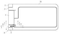
この実施例のジャックのヒンジ部への取付構造は、基本的に、図3、図4及び図6に示すように、携帯電話の端末の二つに分けた支分体1a、1b相互を折り畳み可能に結合するヒンジ部hのヒンジ管内に挿入配置するジャックjの取付構造である。 As shown in FIG. 3, FIG. 4, and FIG. 6, the structure for attaching the jack to the hinge portion of this embodiment basically folds the two
前記ヒンジ部hの端部の固定ヒンジ管2及びその内側の可動ヒンジ管3に、取付対象のジャックjを挿入し、該ジャックj及び該固定ヒンジ管2に該ジャックjの回転を防止する回転防止手段を構成し、かつ該ジャックj及び該固定ヒンジ管2に該ジャックjの軸方向移動防止手段の一部をなす押し込み規制手段を、該ジャックj及び前記可動ヒンジ管3との間に該軸方向移動防止手段の他の一部をなす引き抜き規制手段を、それぞれ構成し、加えて、前記固定ヒンジ管2と前記可動ヒンジ管3との間にはそれらの軸心を中心とする後者の回転自在な回転を確保する回転確保手段を構成すると共に、前記ジャックjと該可動ヒンジ管3との間には、該可動ヒンジ管3の回転確保手段による回転自在な状態を保持するための保持手段を構成したものである。更に該ジャックjの外周と可動ヒンジ管3の内周との間には、可動ヒンジ管3の内周を該ジャックjの外周面と接触させないようにする趣旨及び該ジャックjの端子部からのリード線L等を通すための通路を確保する趣旨でそれらのための十分な隙間をあけるように構成する。 Rotation for preventing the rotation of the jack j into the jack j and the
前記ヒンジ部hは、この実施例では、図1(a)、(b)及び図5に示すように、両端の固定ヒンジ管2、2と各々その直近内側の可動ヒンジ管3、3と、該可動ヒンジ管3、3の間に配された半割部材4からなる。該固定ヒンジ管2、2及び該半割部材4は前記支分体1aの端部から突出させ、該可動ヒンジ管3、3は他の支分体1bの端部から突出させ、相互に軸心を一致させた状態に組み立てたものである。固定ヒンジ管2、2の「固定」及び可動ヒンジ管3、3の「可動」は、いずれも便宜的な表現であり、支分体1a、1bのヒンジ部hを中心とする開閉は、実際には、該固定ヒンジ管2、2及び該可動ヒンジ管3、3の双方が、相互に逆方向に回転することにより行われるものであるが、説明を簡明にする趣旨から、その開閉動作を、一方の固定ヒンジ管2、2が固定状態にあり、他方の可動ヒンジ管3、3が回転動作することにより行われると見なして説明しているものである。 In this embodiment, as shown in FIGS. 1 (a), 1 (b) and 5, the hinge portion h includes fixed
なお、この実施例では、ヒンジ部hへのジャックjの挿入取付は、一方の端部、図1(a)、(b)中では、それぞれ左端側、図5中では、下方側の端部にのみ行う。他端側は、公知の構成が採用され、支分体1a、1bを所望の開閉角度に開いてその状態に保持することなどが可能となっている。前記のように、これは公知の構成であるから、これ以上の説明は省略する。 In this embodiment, the jack j is inserted and attached to the hinge portion h at one end, the left end in FIGS. 1 (a) and 1 (b), and the lower end in FIG. 5, respectively. Only to do. A known structure is adopted for the other end side, and the
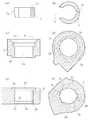
一端の固定ヒンジ管2は、図3(a)、(b)、図4(a)、(b)、図6(a)及び図7(e)、(f)に示すように、その内部は円柱状を基本として形成された円柱空間2aを有し、その内周には、軸方向に延びるキー溝2bと、同様に軸方向に延びる、該キー溝2bに対面する位置関係のリード線用空間2cとが構成してある。また該固定ヒンジ管2には、その前端である開口部に、大径開口部2dが形成してあり、キー溝2bの前端の部分を除いて、該大径開口部2dより所定寸法だけ後方側には、その径が縮小する係止段差部2eを形成してある。加えて、該固定ヒンジ管2の後端には、内周側を削除して大径部2fを形成してある。 As shown in FIGS. 3 (a), 3 (b), 4 (a), 4 (b), 6 (a) and 7 (e), (f), the fixed
前記キー溝2bは、前記ジャックjのハウジング5の外周に形成した後記キー部5aと共に、該ジャックjの回転防止手段を構成するものである。
前記リード線用空間2cは、ジャックjの後述するスリーブバネ6aの端子部に接続したリード線Lを通過させるための空間であり、該固定ヒンジ管2の前端から後端まで軸方向に延びる拡大された空間である。
前記係止段差部2eは、ジャックjを固定ヒンジ管2及び可動ヒンジ管3に挿入した場合に、そのハウジング5の前端部の拡大頭部(先端係止部)5bの後部縁がこれに係止して、該ジャックjの軸方向移動防止手段の一部をなす押し込み規制手段を構成するものである。
また、前記大径部2fは、前記可動ヒンジ管3の前端側に構成した後記小径部3bと共に、前記固定ヒンジ管2に対する該可動ヒンジ管3の回転自在な結合を確保する回転確保手段を構成するものである。The
The
When the jack j is inserted into the fixed
The large-
前記可動ヒンジ管3は、図3(a)、(b)、図4(a)、(b)、図6(b)、(c)及び図7(c)、(d)に示すように、その内部は円柱状を基本として形成された円柱空間3aとなっており、その前端には、外周側を削除して、前記固定ヒンジ管2の後端の大径部2fと回転自在に嵌合する小径部3bを形成し、更に後端には、後記保持用スリップ環(規制環)7の前端がこれに嵌合しつつその段差部3c1に当接する当接保持用大径部3cを形成したものである。 As shown in FIGS. 3 (a), 3 (b), 4 (a), 4 (b), 6 (b), 6 (c) and 7 (c), (d), the
前記小径部3bは、前記したように、前記固定ヒンジ管2の後端の大径部2fに回転自在に嵌合して、該大径部2fと共に回転確保手段を構成するものであり、前記当接保持用大径部3cは、前記保持用スリップ環7と共に、該可動ヒンジ管3の回転確保手段による回転自在な状態を保持するための保持手段を構成するものである。なお、この保持手段は、挿入配置されるジャックjに負荷を掛けずに、可動ヒンジ管3の回転自在な配設状態を保持する趣旨もある。 As described above, the small-
前記保持用スリップ環7は、図3(a)、(b)、図4(a)、(b)、図6(c)、(d)及び図7(a)、(b)に示すように、断面ほぼC型の環状部材であり、その外径は、前記可動ヒンジ管3の当接保持用大径部3cに相対的にスライド回転自在に嵌合し得る寸法とし、内径はジャックjをスムーズに挿入可能とすべく、その外径を僅かに越える寸法とする。また該保持用スリップ環7には、その環状の構成を一部切り欠いたリード線L等の案内用切欠部7aを形成し、該案内用切欠部7aの中心部から180度の角度間隔の部位の内周にその軸心に沿ったキー溝7bを形成したものである。 The holding
該保持用スリップ環7は、前記したように、前記可動ヒンジ管3の当接保持用大径部3cと共に、該可動ヒンジ管3の回転確保手段による回転自在な状態を保持するための保持手段を構成し、同時に、前記したように、該可動ヒンジ管3の回転動作に拘わらず、ジャックjにそれによる負荷を掛けないようにしながら、該ジャックjを保持するものでもある。 As described above, the holding
前記キー溝7bは、前記ジャックjを、前記固定ヒンジ管2及び可動ヒンジ管3に挿入し、その後端部を前記保持用スリップ環7に嵌合させた場合に、該ジャックjのハウジング5の後端側に構成したキー部5cが進入嵌合する溝空間である。該ジャックjは、それ自体の軸心を中心とする回転が、その前部側に構成したキー部5aが前記固定ヒンジ管2のキー溝2bに嵌合することで防止され、該ジャックjのハウジング5の後端側のキー部5cが前記キー溝7bに進入嵌合することで、該キー溝7bを構成した保持用スリップ環7の回転を防止できるようになっているものでもある。 When the jack j is inserted into the fixed
こうして該保持用スリップ環7の案内用切欠部7aを通過するリード線L等は、固定ヒンジ管2に対する可動ヒンジ管3の相対的な回転動作が行われた場合にも、該保持用スリップ環7の該固定ヒンジ管2に対する関係での回転が生じるようなことはないため、それに無用の外力が加えられたりする虞はない。即ち、該リード線L等の案内路は確実に保護され、該リード線L等に損傷を生じるような虞はない。 Thus, the lead wire L and the like passing through the
なお、該保持用スリップ環7は、それが後端側方向(前記固定ヒンジ管2の開口部側と反対方向)に移動すると、その先端側の可動ヒンジ管3の当接保持用大径部3cとの嵌合が解消することとなり、これによる前記可動ヒンジ管3の回転自在な状態を保持するための保持手段としての機能が失われてしまう。それ故、該保持用スリップ環7の先端部と該可動ヒンジ管3の後部の当接保持用大径部3cとの嵌合を保持すべく、該保持用スリップ環7の後方への移動を阻止する後方移動規制手段が必要であり、そのために、この実施例では、ジャックjのハウジング5後部に係止したC型止め輪(環状板部材)8を該後方移動規制手段として用いる。 When the holding
該C型止め輪8は、図8に示すように、文字通り円環部の一部が欠け、欠けた部分の両側からほぼ対面状態に立ち上がる概ねU字形の操作片8a、8aを備えた部分環状の板材であり、弾力性を有する素材によって構成したものである。これは、その内径を、ジャックjのハウジング5の後端近傍に円環状に形成した環状係止溝5dにほぼ一致するように形成したものであり、その弾力を利用して該環状係止溝5dに係止させ、図4(a)、(b)に示すように、該ジャックjに外装しながら可動ヒンジ管3を後方に動かないように規制している前記保持用スリップ環7の後端に当接し、その後方への移動を規制するよう機能するものである。また該C型止め輪8は、同時に、これが該環状係止溝5dを介して結合しているジャックjの前方への移動を、該C型止め輪8が該保持用スリップ環7の後端に当接することにより、阻止すべく作用しているものでもある。 As shown in FIG. 8, the C-type retaining ring 8 is a partial annular shape having substantially
前記ジャックjは、図9(a)〜(e)、図10(a)〜(d)及び図11(a)、(b)に示すように、基本的に、ハウジング5と、スリーブバネ6a、リングバネ6b及びチップバネ6cとからなる。 The jack j basically has a
該ハウジング5は、同図に示すように、前端にプラグ挿入孔5eを開口した円筒状を基本とする部材であり、その前端には、若干拡大した円形の拡大頭部(先端係止部)5bを備え、前部周側の一部には軸方向に延長するキー部5aを、その延長上の後部周側にも同様のキー部5cを、それぞれ形成し、更に後部のキー部5cより後方の部位には、前記C型止め輪8の厚みにほぼ一致する溝幅の環状係止溝5dを形成したものである。 As shown in the figure, the
該ハウジング5は、更に、その前部及び中間部の周側に、順次、スリーブバネ6a用の取付凹部及びリングバネ6b用の取付凹部を備え、後部内周にはチップバネ6c用の取付溝を備えており、同図に示すように、これらの取付凹部又は取付溝に取り付けたスリーブバネ6a、リングバネ6b及びチップバネ6cは、そのいずれの部分も、該ハウジング5の周側部外面より外方に突出しないようになっている。 The
前記プラグ挿入孔5eは、ハウジング5の長さ方向に沿ってその円筒状外周とほぼ同軸状に前端から後端まで延長状態に構成したものであり、前記拡大頭部5bは、前記固定ヒンジ管2の大径開口部2dに嵌合し得る外径寸法となっている。前記前端側のキー部5aは、前記固定ヒンジ管2の前端側のキー溝2bにスライド自在に進入し得る幅寸法とし、前記後端側のキー部5cも同幅とし、かつ前記保持用スリップ環7のキー溝7bにスライド自在に進入し得るものとする。また前記環状係止溝5dは、ジャックjを固定ヒンジ管2及び可動ヒンジ管3にセットした状態で、前記C型止め輪8を該環状係止溝5dに嵌合させると、そのC型止め輪8の前面側が、可動ヒンジ管3の当接保持用大径部3cに嵌合した状態の保持用スリップ環7の後端に当接状態になる位置関係にハウジング5の外周後部に形成する。 The
前記スリーブバネ6aは、図9(b)、(d)、(e)、図10(a)、(c)、(d)及び図11に示すように、中央部の基板部と、該基板部の両側両端から延長した抱持片と、該基板部の両側中央部から延長したコンタクト片とからなる。従ってこのスリーブバネ6aは、次のようにしてハウジング5に組み込む。即ち、前記ハウジング5の周側前部側の取付凹部のキー部5aと反対側に位置する部位に、基板部を配し、その両側両端から延長する抱持片で該ハウジング5の周側を抱持し、両側中央から延長するコンタクト片を同方向に延長すると共に、延長方向途中に開口したコンタクト導入口からプラグ挿入孔5eの側方に進入させる。このスリーブバネ6aは、以上のように該当する取付凹部に配することにより、そのコンタクト片が、プラグ挿入孔5eに挿入されたプラグpのスリーブ電極に接触するように位置決めされる。 As shown in FIGS. 9 (b), (d), (e), FIGS. 10 (a), (c), (d) and FIG. A holding piece extending from both ends of the substrate portion, and a contact piece extending from the central portion on both sides of the substrate portion. Therefore, the
前記リングバネ6bは、それ自体の構成は、スリーブバネ6aと全く同様であり、図9(b)、(d)、(e)、図10(c)、(d)及び図11に示すように、中央部の基板部と、該基板部の両側両端から延長した抱持片と、該基板部の両側中央部から延長したコンタクト片とからなる。該リングバネ6bも、前記ハウジング5の周側の中間部の取付凹部にスリーブバネ6aの配置の仕方と全く同様に配置することにより、そのコンタクト片で、プラグ挿入孔5eに挿入されたプラグpのリング電極に接触するように位置決めされる。 The structure of the
前記チップバネ6cは、図9(a)〜(e)、図10(a)〜(d)及び図11に示すように、中央基部の両側から延長した二つの対面する取付片と、両端から延長した二つの対面するコンタクト片とからなり、前記ハウジング5の背後からその内側に挿入し、取付片を取付溝に挿入係止させ、コンタクト片をプラグ挿入孔5eの内周両側に位置させる。この状態で、コンタクト片は、該プラグ挿入孔5eに挿入されたプラグpのチップ電極に挟持状態に当接するように位置決めされる。 As shown in FIGS. 9 (a) to 9 (e), 10 (a) to (d) and FIG. 11, the
従ってこのジャックのヒンジ部への取付構造によれば、ヒンジ部hへのジャックjの組込みは以下のように容易に行うことができる。 Therefore, according to the mounting structure of the jack to the hinge portion, the jack j can be easily assembled into the hinge portion h as follows.
まず前記固定ヒンジ管2と前記半割部材4との間に前記可動ヒンジ管3を挿入する。該固定ヒンジ管2と該半割部材4との間の間隔は、該可動ヒンジ管3の軸方向の長さ寸法とその小径部3bの軸方向の長さ寸法を加えた長さ寸法を僅かに越えた寸法に構成されている。それ故、該可動ヒンジ管3は、その間に挿入可能であり、挿入後、その軸心と固定ヒンジ管2の軸心とを一致させた上で、該可動ヒンジ管3の前端の小径部3bを、該固定ヒンジ管2の後端の大径部2fにスライド回転自在に嵌合させる。 First, the
この後、該可動ヒンジ管3の後部の当接保持用大径部3cに前記保持用スリップ環7の前端を嵌合させつつ前者の段差部3c1に後者の前端を当接させる。該保持用スリップ環7の当接保持用大径部3cとの嵌合動作は、前記半割部材4の内側を通じて後方から行うことができる。以上の当接保持用大径部3cへの保持用スリップ環7の前端の嵌合は、相対的に回転自在な結合となるものである。なお、このとき、該保持用スリップ環7は、その内周のキー溝7bが、前記固定ヒンジ管2の内周のキー溝2bと同一直線上に位置することとなるように、当接保持用大径部3cへの嵌合時の回転方向の角度関係を調節する。 Thereafter, the front end of the latter is brought into contact with the former step portion 3c1 while the front end of the holding
更にこの後、前記ジャックjを前記固定ヒンジ管2の前端の大径開口部2d側から挿入する。このとき、ジャックjは、そのキー部5a、5cを、該固定ヒンジ管2のキー溝2bに一致させ、該キー部5c、次いで該キー部5aを、該キー溝2b中に進入させ、更にこの中をスライド移動させつつ、該ジャックjを、該固定ヒンジ管2及び前記可動ヒンジ管3、更には前記保持用スリップ環7中に挿入する。 Thereafter, the jack j is inserted from the large-
該ジャックjは、以上の挿入過程で、該可動ヒンジ管3中を通過するところでは非接触で中空を移動し、該保持用スリップ環7中に進入すると、その後部外周のキー部5cが該保持用スリップ環7のキー溝7bに進入し、この中をスライドしながら進行し、ハウジング5の前端の拡大頭部5bが固定ヒンジ管2の前端の大径開口部2dに嵌合し、該拡大頭部5bの後端が該大径開口部2dの後部の係止段差部2eに係止して、それ以上のジャックjの進入が阻止されることになる。 When the jack j passes through the
その後、ジャックjのハウジング5の後部外周に形成してある環状係止溝5dにC型止め輪8を外装嵌合させる。これは、該C型止め輪8を、その弾力性を利用して変形させることにより行うものである。こうして、図4(a)、(b)に示すように、該C型止め輪8を該ハウジング5の環状係止溝5dに嵌合させると、その前面側が前記保持用スリップ環7の後端に当接し、その後方への移動を防止し、可動ヒンジ管3前端の小径部3bと固定ヒンジ管2の大径部2fとの確実な嵌合が確保され、該可動ヒンジ管3は、回転自在な状態が保持されることになる。 Thereafter, the C-type retaining ring 8 is externally fitted into an
また、該C型止め輪8の前面側が前記保持用スリップ環7の後端に当接することで、その前方(固定ヒンジ管2側)への移動が阻止され、ジャックjの引き抜き方向への動きが規制されることになる。該ジャックjは、前端では、前記のように、その拡大頭部5bが固定ヒンジ管2の係止段差部2eに係止して、その押し込み方向の移動が阻止されているので、結局、軸方向の動きが完全に規制されることになる。 Further, since the front side of the C-type retaining ring 8 abuts the rear end of the holding
なお、以上のように、ジャックjをヒンジ部hの固定ヒンジ管2及び可動ヒンジ管3等の内部に挿入する前に、予め前記スリーブバネ6a及びリングバネ6bの端子部にはリード線Lを接続し、該リード線Lは該端子部の配してある部位から該ハウジング5の長さ方向に沿って周側に配しておくこととする。またチップバネ6cの取付片の一部にも同様にリード線Lを接続してハウジング5外に引き出し、スリーブバネ6a及びリングバネ6bの端子部から引き出したリード線Lに隣接する位置まで延長し、同様に、周側に配して後方に向かって延長しておくこととする。 As described above, the lead wire L is connected to the terminal portions of the
従って前記のように、固定ヒンジ管2及び可動ヒンジ管3等にジャックjを挿入する際に、以上の三本のリード線Lは、固定ヒンジ管2の内部では、拡大されているリード線用空間2c中に位置し、可動ヒンジ管3中では、内周全体の内径が、固定ヒンジ管のリード線用空間2c側の半径とほぼ同一の半径となっている内部空間中に位置するため、その挿入過程で、損傷を生じるような虞はない。更にそれより後方では、前記保持用スリップ環7の不連続部であるリード線L等の案内用切欠部7a内を通過するため、ここでも何らの支障が生じることもない。 Therefore, as described above, when the jack j is inserted into the fixed
また固定ヒンジ管2は、ジャックjとの関係では、相互に固定状態で回転することはないため、前記リード線Lがそのリード線用空間2cから外れることはない。可動ヒンジ管3は、その内周が全周に渡って大径となっているため、それが回転してもその内部空間の広さに影響を与えることがない。それ故、可動ヒンジ管3が回転してもその内部に位置するリード線Lには何らの支障が生じることもない。また前記保持用スリップ環7は、そのキー溝7bにジャックjのハウジング5のキー部5cが嵌合しているため、可動ヒンジ管3が回転しても、これに伴って回転するようなことはない。それ故、前記のように、案内用切欠部7aを通過するリード線Lも該案内用切欠部7aが一定位置に固定されているので、何らの支障が生じる虞もない。 Further, since the fixed
なお、ジャックjは、その前部側のキー部5aが固定ヒンジ管2のキー溝2bに嵌合しているため、固定ヒンジ管2に固定されており、可動ヒンジ管3が回転してもそれに伴って回転するようなことはない。 The jack j is fixed to the fixed
以上の通りであり、この実施例のジャックのヒンジ部への取付構造によれば、ジャックjをその中に挿入配置しても、ヒンジ部hの可動ヒンジ管3の回転が妨げられることはなく、かつ挿入したジャックjに負荷が掛かることもなく、それ故、何らかの支障が生じることもない。またジャックjの挿入取付作業も、以上のように、極めて簡単である。 As described above, according to the mounting structure of the jack to the hinge portion of this embodiment, even if the jack j is inserted and arranged therein, the rotation of the
1a、1b 支分体
2 固定ヒンジ管
2a 固定ヒンジ管の円柱空間
2b 固定ヒンジ管の前部内周のキー溝
2c リード線用空間
2d 大径開口部
2e 係止段差部
2f 固定ヒンジ管の大径部
3 可動ヒンジ管
3a 可動ヒンジ管の円柱空間
3b 可動ヒンジ管の小径部
3c 当接保持用大径部
3c1 当接保持用大径部の段差部
4 半割部材
5 ハウジング
5a キー部
5b 拡大頭部
5c ハウジングのキー部
5d 環状係止溝
5e プラグ挿入孔
6a スリーブバネ
6b リングバネ
6c チップバネ
7 保持用スリップ環(規制環)
7a 案内用切欠部
7b 保持用スリップ環のキー溝
8 C型止め輪(環状板部材)
8a 操作片
h ヒンジ部
j ジャック
L リード線
p プラグDESCRIPTION OF
8a Operation piece h Hinge j Jack L Lead wire p Plug
Claims (4)
Translated fromJapaneseヒンジ部の端部側のヒンジ管及びその内側の一以上のヒンジ管内にジャックを配置し、
該ジャックと端部側のヒンジ管とに該ジャックの回転を防止する回転防止手段を構成し、
該ジャック及び一以上のヒンジ管に、該ジャックの軸方向の移動を防止する軸方向移動防止手段を構成し、
端部から数えて偶数番目のヒンジ管を奇数番目のヒンジ管に対して、それらの軸心を回転中心として相対的に回転自在に結合し、
かつ該ジャックの外周と偶数番目のヒンジ管の内周との間に隙間をあけるように構成したジャックのヒンジ部への取付構造。A structure for mounting a jack to a hinge portion, wherein the jack is inserted and arranged in a hinge portion that foldably connects the branch bodies of the portable terminal,
The jack is arranged in the hinge tube on the end side of the hinge portion and one or more hinge tubes inside the hinge tube,
The jack and the hinge tube on the end side constitute a rotation preventing means for preventing the jack from rotating,
The jack and the one or more hinge pipes are configured with axial movement preventing means for preventing the jack from moving in the axial direction,
The even-numbered hinge pipes counted from the end are coupled to the odd-numbered hinge pipes so as to be relatively rotatable with their axis as the center of rotation.
And a jack mounting structure for a jack configured to open a gap between the outer periphery of the jack and the inner periphery of the even-numbered hinge pipe.
Priority Applications (2)
| Application Number | Priority Date | Filing Date | Title |
|---|---|---|---|
| JP2008114424AJP4454669B2 (en) | 2008-04-24 | 2008-04-24 | Jack mounting structure on hinge |
| CN2008101740046ACN101568231B (en) | 2008-04-24 | 2008-11-11 | Installation structure with hinge towards plug socket |
Applications Claiming Priority (1)
| Application Number | Priority Date | Filing Date | Title |
|---|---|---|---|
| JP2008114424AJP4454669B2 (en) | 2008-04-24 | 2008-04-24 | Jack mounting structure on hinge |
Publications (2)
| Publication Number | Publication Date |
|---|---|
| JP2009267732A JP2009267732A (en) | 2009-11-12 |
| JP4454669B2true JP4454669B2 (en) | 2010-04-21 |
Family
ID=41284093
Family Applications (1)
| Application Number | Title | Priority Date | Filing Date |
|---|---|---|---|
| JP2008114424AExpired - Fee RelatedJP4454669B2 (en) | 2008-04-24 | 2008-04-24 | Jack mounting structure on hinge |
Country Status (2)
| Country | Link |
|---|---|
| JP (1) | JP4454669B2 (en) |
| CN (1) | CN101568231B (en) |
Families Citing this family (4)
| Publication number | Priority date | Publication date | Assignee | Title |
|---|---|---|---|---|
| US9176537B2 (en) | 2013-03-15 | 2015-11-03 | Intel Corporation | Connector assembly for an electronic device |
| TWI811743B (en)* | 2021-07-22 | 2023-08-11 | 仁寶電腦工業股份有限公司 | Foldable electronic device |
| CN117425443A (en)* | 2022-03-28 | 2024-01-19 | 江苏唯德康医疗科技有限公司 | Medical closing clamp |
| CN115513721B (en)* | 2022-10-31 | 2025-04-25 | 南通理工学院 | Power supply equipment for bridge inspection system |
Family Cites Families (1)
| Publication number | Priority date | Publication date | Assignee | Title |
|---|---|---|---|---|
| CN2615972Y (en)* | 2003-04-15 | 2004-05-12 | 杭州波导软件有限公司 | Folding cell phone |
- 2008
- 2008-04-24JPJP2008114424Apatent/JP4454669B2/ennot_activeExpired - Fee Related
- 2008-11-11CNCN2008101740046Apatent/CN101568231B/ennot_activeExpired - Fee Related
Also Published As
| Publication number | Publication date |
|---|---|
| JP2009267732A (en) | 2009-11-12 |
| CN101568231A (en) | 2009-10-28 |
| CN101568231B (en) | 2012-07-04 |
Similar Documents
| Publication | Publication Date | Title |
|---|---|---|
| US8086285B2 (en) | Carrying cases having sound enhancing capability, for portable communication devices | |
| US6708046B1 (en) | Folding portable telephone having enhanced operability | |
| JP4454669B2 (en) | Jack mounting structure on hinge | |
| JP2006233998A5 (en) | ||
| JP2004328279A (en) | Portable terminal machine | |
| KR20030071284A (en) | Hinge device and portable terminal therewith | |
| JP2008138875A (en) | Hinge mechanism | |
| JP2009268050A (en) | Slidable-turnable attachment unit and portable telephone using the same | |
| CN101660569A (en) | Hinge mechanism and portable electronic device using same | |
| WO2018120066A1 (en) | Display device and mobile terminal | |
| CN102116345B (en) | Hinge structure | |
| JP4173185B1 (en) | Mobile device | |
| US20080134468A1 (en) | Pivotal device | |
| JP4733678B2 (en) | Portable device | |
| KR200468496Y1 (en) | Cases for Haiti Devices with Mounting Means | |
| JP5016395B2 (en) | Hinge device for portable device and portable device | |
| JP4925686B2 (en) | Pivot support structure of lid and electric device provided with the structure | |
| CN110544853A (en) | Coaxial connector device including locking member and locking member | |
| CN205647892U (en) | Cell phone stand formula earphone spooler | |
| KR100610373B1 (en) | Bidirectional hinge device and portable terminal having same | |
| KR100641325B1 (en) | Bidirectional hinge device and portable terminal having same | |
| CN213025392U (en) | A clamshell storage assembly | |
| CN222823989U (en) | A bracket assembly | |
| JP4443261B2 (en) | Portable electronic devices | |
| KR20070000060A (en) | Hinge device and mobile terminal thereof |
Legal Events
| Date | Code | Title | Description |
|---|---|---|---|
| A977 | Report on retrieval | Free format text:JAPANESE INTERMEDIATE CODE: A971007 Effective date:20100129 | |
| TRDD | Decision of grant or rejection written | ||
| A01 | Written decision to grant a patent or to grant a registration (utility model) | Free format text:JAPANESE INTERMEDIATE CODE: A01 Effective date:20100202 | |
| A01 | Written decision to grant a patent or to grant a registration (utility model) | Free format text:JAPANESE INTERMEDIATE CODE: A01 | |
| A61 | First payment of annual fees (during grant procedure) | Free format text:JAPANESE INTERMEDIATE CODE: A61 Effective date:20100202 | |
| FPAY | Renewal fee payment (event date is renewal date of database) | Free format text:PAYMENT UNTIL: 20130212 Year of fee payment:3 | |
| R150 | Certificate of patent or registration of utility model | Free format text:JAPANESE INTERMEDIATE CODE: R150 | |
| LAPS | Cancellation because of no payment of annual fees |