JP4452782B2 - Multiple loop antenna for RFID reader, RFID reader having the same, and RFID system having the same - Google Patents
Multiple loop antenna for RFID reader, RFID reader having the same, and RFID system having the sameDownload PDFInfo
- Publication number
- JP4452782B2 JP4452782B2JP2007000548AJP2007000548AJP4452782B2JP 4452782 B2JP4452782 B2JP 4452782B2JP 2007000548 AJP2007000548 AJP 2007000548AJP 2007000548 AJP2007000548 AJP 2007000548AJP 4452782 B2JP4452782 B2JP 4452782B2
- Authority
- JP
- Japan
- Prior art keywords
- rfid reader
- loop antenna
- rfid
- winding group
- parallel
- Prior art date
- Legal status (The legal status is an assumption and is not a legal conclusion. Google has not performed a legal analysis and makes no representation as to the accuracy of the status listed.)
- Expired - Fee Related
Links
Images


Classifications
- H—ELECTRICITY
- H04—ELECTRIC COMMUNICATION TECHNIQUE
- H04B—TRANSMISSION
- H04B5/00—Near-field transmission systems, e.g. inductive or capacitive transmission systems
- H04B5/20—Near-field transmission systems, e.g. inductive or capacitive transmission systems characterised by the transmission technique; characterised by the transmission medium
- H04B5/24—Inductive coupling
- H—ELECTRICITY
- H01—ELECTRIC ELEMENTS
- H01Q—ANTENNAS, i.e. RADIO AERIALS
- H01Q7/00—Loop antennas with a substantially uniform current distribution around the loop and having a directional radiation pattern in a plane perpendicular to the plane of the loop
- H01Q7/04—Screened antennas
- G—PHYSICS
- G06—COMPUTING OR CALCULATING; COUNTING
- G06K—GRAPHICAL DATA READING; PRESENTATION OF DATA; RECORD CARRIERS; HANDLING RECORD CARRIERS
- G06K7/00—Methods or arrangements for sensing record carriers, e.g. for reading patterns
- G06K7/0008—General problems related to the reading of electronic memory record carriers, independent of its reading method, e.g. power transfer
- G—PHYSICS
- G06—COMPUTING OR CALCULATING; COUNTING
- G06K—GRAPHICAL DATA READING; PRESENTATION OF DATA; RECORD CARRIERS; HANDLING RECORD CARRIERS
- G06K7/00—Methods or arrangements for sensing record carriers, e.g. for reading patterns
- G06K7/10—Methods or arrangements for sensing record carriers, e.g. for reading patterns by electromagnetic radiation, e.g. optical sensing; by corpuscular radiation
- G06K7/10009—Methods or arrangements for sensing record carriers, e.g. for reading patterns by electromagnetic radiation, e.g. optical sensing; by corpuscular radiation sensing by radiation using wavelengths larger than 0.1 mm, e.g. radio-waves or microwaves
- G06K7/10316—Methods or arrangements for sensing record carriers, e.g. for reading patterns by electromagnetic radiation, e.g. optical sensing; by corpuscular radiation sensing by radiation using wavelengths larger than 0.1 mm, e.g. radio-waves or microwaves using at least one antenna particularly designed for interrogating the wireless record carriers
- G06K7/10336—Methods or arrangements for sensing record carriers, e.g. for reading patterns by electromagnetic radiation, e.g. optical sensing; by corpuscular radiation sensing by radiation using wavelengths larger than 0.1 mm, e.g. radio-waves or microwaves using at least one antenna particularly designed for interrogating the wireless record carriers the antenna being of the near field type, inductive coil
- H—ELECTRICITY
- H01—ELECTRIC ELEMENTS
- H01Q—ANTENNAS, i.e. RADIO AERIALS
- H01Q1/00—Details of, or arrangements associated with, antennas
- H01Q1/12—Supports; Mounting means
- H01Q1/22—Supports; Mounting means by structural association with other equipment or articles
- H01Q1/2208—Supports; Mounting means by structural association with other equipment or articles associated with components used in interrogation type services, i.e. in systems for information exchange between an interrogator/reader and a tag/transponder, e.g. in Radio Frequency Identification [RFID] systems
- H01Q1/2216—Supports; Mounting means by structural association with other equipment or articles associated with components used in interrogation type services, i.e. in systems for information exchange between an interrogator/reader and a tag/transponder, e.g. in Radio Frequency Identification [RFID] systems used in interrogator/reader equipment
- H—ELECTRICITY
- H01—ELECTRIC ELEMENTS
- H01Q—ANTENNAS, i.e. RADIO AERIALS
- H01Q1/00—Details of, or arrangements associated with, antennas
- H01Q1/12—Supports; Mounting means
- H01Q1/22—Supports; Mounting means by structural association with other equipment or articles
- H01Q1/2208—Supports; Mounting means by structural association with other equipment or articles associated with components used in interrogation type services, i.e. in systems for information exchange between an interrogator/reader and a tag/transponder, e.g. in Radio Frequency Identification [RFID] systems
- H01Q1/2225—Supports; Mounting means by structural association with other equipment or articles associated with components used in interrogation type services, i.e. in systems for information exchange between an interrogator/reader and a tag/transponder, e.g. in Radio Frequency Identification [RFID] systems used in active tags, i.e. provided with its own power source or in passive tags, i.e. deriving power from RF signal
- H—ELECTRICITY
- H01—ELECTRIC ELEMENTS
- H01Q—ANTENNAS, i.e. RADIO AERIALS
- H01Q7/00—Loop antennas with a substantially uniform current distribution around the loop and having a directional radiation pattern in a plane perpendicular to the plane of the loop
- H—ELECTRICITY
- H01—ELECTRIC ELEMENTS
- H01Q—ANTENNAS, i.e. RADIO AERIALS
- H01Q7/00—Loop antennas with a substantially uniform current distribution around the loop and having a directional radiation pattern in a plane perpendicular to the plane of the loop
- H01Q7/02—Collapsible antennas; Retractable antennas
Landscapes
- Engineering & Computer Science (AREA)
- Physics & Mathematics (AREA)
- Toxicology (AREA)
- Health & Medical Sciences (AREA)
- Computer Networks & Wireless Communication (AREA)
- Theoretical Computer Science (AREA)
- General Physics & Mathematics (AREA)
- Computer Vision & Pattern Recognition (AREA)
- Artificial Intelligence (AREA)
- Electromagnetism (AREA)
- General Health & Medical Sciences (AREA)
- Signal Processing (AREA)
- Near-Field Transmission Systems (AREA)
- Variable-Direction Aerials And Aerial Arrays (AREA)
Description
Translated fromJapanese本発明はRFIDリーダ用多重ループアンテナに関し、より詳しくは、電磁気誘導によりRFIDタグに記憶された情報を読み取ったり、該RFIDタグに新しい情報を書き込むためのRFIDリーダに使用される多重ループアンテナに関する。 The present invention relates to a multiple loop antenna for an RFID reader, and more particularly to a multiple loop antenna used in an RFID reader for reading information stored in an RFID tag by electromagnetic induction or writing new information to the RFID tag.
RFIDタグは、内部にメモリが存在するICチップとアンテナとから構成され、携帯可能な物品(以下、「非接触式携帯物品」という)に取り付けられるように設置されるか、又はその一部をなすように設置される。電磁気誘導により前記RFIDタグのメモリに記憶された情報を読み取るために、又は、前記RFIDタグのメモリに記憶された情報を読み取ったり該RFIDタグのメモリに新しい情報を書き込むためには、RFIDリーダを使用する。 An RFID tag is composed of an IC chip having an internal memory and an antenna, and is installed so as to be attached to a portable article (hereinafter referred to as “non-contact portable article”) or a part thereof. It will be installed as if To read information stored in the RFID tag memory by electromagnetic induction, or to read information stored in the RFID tag memory or write new information to the RFID tag memory, an RFID reader is used. use.
前記RFIDリーダは、前記RFIDタグが設置された非接触式携帯物品を所持した者が、前記RFIDリーダの前面に前記非接触式携帯物品を所定距離内に接近させると、前記非接触式携帯物品との電磁気誘導により、非接触式送受信方式(RF方式の送受信)で情報を入出力して情報を交換する。 The RFID reader is configured such that when a person who has a non-contact type portable article with the RFID tag installed brings the non-contact type portable article close to a front surface of the RFID reader within a predetermined distance, the non-contact type portable article The information is exchanged by inputting and outputting information by a non-contact type transmission / reception system (RF system transmission / reception).
前記RFIDタグが設置された非接触式携帯物品(非接触式ICカード、無線決済携帯電話、及び無線身元確認用物品など)は、電源を備えた前記RFIDリーダと電磁気誘導により情報を送信及び受信する。 Non-contact portable articles (such as non-contact IC cards, wireless payment mobile phones, and wireless identity confirmation articles) on which the RFID tag is installed transmit and receive information by the RFID reader equipped with a power source and electromagnetic induction. To do.
これと類似した形態として、既存のバーコードの代わりにICチップを備えてその内部に商品情報を記憶させた商品(以下、「非接触式商品」という)にも、その内部にアンテナと情報記憶用メモリとを含むRFIDタグを設置することができ、電源を備えた前記RFIDリーダと電磁気誘導により情報を送信及び受信する。 As a similar form, a product (hereinafter referred to as “non-contact product”) having an IC chip instead of an existing bar code and storing product information stored therein stores an antenna and information therein. An RFID tag including a storage memory can be installed, and information is transmitted and received by the RFID reader equipped with a power source and electromagnetic induction.
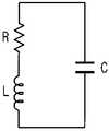
このような非接触式携帯物品又は非接触式商品と情報を交換するためのRFIDリーダも、その内部又は外部にアンテナを備えなければならず、特に、ISO14443に該当するICカード、携帯電話などの物品、及びISO15693に該当する無線認識においては規定された周波数、すなわち、13.56MHzの信号が規格で使用されているので、全体回路が前記周波数付近で共振するように構成する必要がある。 An RFID reader for exchanging information with such a non-contact type portable article or non-contact type product must also have an antenna inside or outside thereof, in particular, an IC card corresponding to ISO 14443, a mobile phone, etc. In the wireless recognition corresponding to the article and ISO 15693, a signal having a prescribed frequency, that is, a signal of 13.56 MHz is used in the standard. Therefore, it is necessary to configure the entire circuit to resonate near the frequency.
このような非接触式携帯物品の認識過程において発生する様々な問題の1つは、非接触式携帯物品がRFIDリーダから所定距離離れた場合、RFIDリーダは対象携帯物品を認識できないということである。これは、非接触式携帯物品がRFIDリーダが発生する磁場の範囲のうち、認識可能な最小の大きさより小さい磁場が形成された範囲に位置することによるものである。 One of various problems that occur in the process of recognizing such a non-contact type portable article is that when the non-contact type portable article is separated from the RFID reader by a predetermined distance, the RFID reader cannot recognize the target portable article. . This is because the non-contact portable article is located in a range where a magnetic field smaller than the smallest recognizable size is formed in the range of the magnetic field generated by the RFID reader.
図4は直列給電形態を有する従来のRFIDリーダ用多重ループアンテナを示す概念図であり、図5は並列給電形態を有する従来のRFIDリーダ用多重ループアンテナを示す概念図である。 FIG. 4 is a conceptual diagram showing a conventional multi-loop antenna for an RFID reader having a series power feeding form, and FIG. 5 is a conceptual diagram showing a conventional multi-loop antenna for an RFID reader having a parallel power feeding form.
従来の多重巻線グループを直列に給電するループアンテナにおいては、図4に示すように、ループアンテナ巻線グループ10、20を複数のパターンに設置するが、それぞれの巻線グループ10、20同士は直列に接続される。 In a conventional loop antenna that feeds multiple winding groups in series, as shown in FIG. 4, the loop
従来の大多数のRFIDリーダの内部に使用される単一巻線グループを備えたループアンテナ構造は、RFIDリーダから距離が遠くなると磁場が弱くて十分な認識が行われず、かつ、ワインディング中心部の磁場が弱くて安定性が足りないという欠点があるが、このような欠点を補完するために考案された形態である。 The loop antenna structure having a single winding group used in the majority of conventional RFID readers is not sufficiently recognized when the distance from the RFID reader is increased, and is not sufficiently recognized. Although there is a drawback that the magnetic field is weak and lacks stability, it is a form devised to compensate for this drawback.
しかし、このような形態のループアンテナは、その巻線グループ10、20が直列に接続されており、全体のインダクタンスがそれぞれの巻線グループのインダクタンスより大きくなり、容易にQ(Quality factor)が大きくなる。Qが大きくなると帯域幅が狭くなるという欠点がある。また、同一の電圧を印加した場合、全体の抵抗が大きいため、アンテナに流れる電流が弱くなり、これにより、形成される磁場が弱くなるという問題があった。 However, in such a loop antenna, the
一方、従来の他のRFIDリーダのアンテナ構造として、図5に示すように、多重巻線グループ10、20を並列に給電する場合がある。これは、ループアンテナ巻線グループ10、20を複数のパターンに設置するが、それぞれの巻線グループ10、20同士は並列に接続される。 On the other hand, as an antenna structure of another conventional RFID reader, there are cases where
内部の巻線ループ20と外部の巻線ループ10とは同一方向に巻回されるが、これはアンテナの指向性を改善して認識距離をさらに確保するためである。並列多重ループアンテナの形態で構成する場合、単一ループアンテナに比べて同一ターン数ではインダクタンス値が低くなる。インダクタンスを既存の場合と同一にする場合は、ターン数を増やすことができる。また、外部の巻線グループ20と内部の巻線グループ10とが並列に接続されているため、携帯物品がRFIDリーダに接近するとき、相互間の影響を低減することができる。 The
しかし、このような並列給電のアンテナ構造は、携帯物品の認識可能距離を改善するという効果を有するが、より遠く離れた携帯物品を認識するためには認識可能距離をより改善する必要がある。 However, such a parallel-fed antenna structure has the effect of improving the recognizable distance of the portable article, but it is necessary to further improve the recognizable distance in order to recognize a portable article farther away.
本発明は、前述のような必要性を認識してなされたもので、中心部分でより大きな磁場を形成できるアンテナ構造を提供することにより、携帯物品の認識可能距離を増加させることのできるRFIDリーダ用多重ループアンテナ、これを有するRFIDリーダ、及びこれを有するRFIDシステムを提供することを目的とする。 The present invention has been made in recognition of the necessity as described above, and an RFID reader capable of increasing the recognizable distance of a portable article by providing an antenna structure capable of forming a larger magnetic field in the central portion. It is an object to provide a multi-loop antenna for use, an RFID reader having the same, and an RFID system having the same.
本発明の他の目的は、認識可能距離が改善されたRFIDリーダ用多重ループアンテナ、これを有するRFIDリーダ、及びこれを有するRFIDシステムを提供することにある。 Another object of the present invention is to provide a multiple loop antenna for an RFID reader with an improved recognizable distance, an RFID reader having the same, and an RFID system having the same.
上記の目的を達成するために、本発明は、RFIDタグと電磁気誘導により情報を交換するためのRFIDリーダ用ループアンテナであって、1回以上巻回された3つ以上の巻線グループを含み、前記それぞれの巻線グループが直列及び並列に接続されていることを特徴とするRFIDリーダ用多重ループアンテナを開示する。 To achieve the above object, the present invention is an RFID reader loop antenna for exchanging information with an RFID tag by electromagnetic induction, and includes three or more winding groups wound at least once. A multiple loop antenna for an RFID reader is disclosed in which the respective winding groups are connected in series and in parallel.
前記それぞれの巻線グループは全て同一方向に巻回することができ、前記それぞれの巻線グループは間隔をおいて設置することができる。 The respective winding groups can all be wound in the same direction, and the respective winding groups can be installed at intervals.
前記RFIDタグは物品の一部をなすように構成することができ、前記物品は携帯用物品であり得る。 The RFID tag can be configured to form part of an article, and the article can be a portable article.
また、本発明は、前述のような構造を有する多重ループアンテナを含むRFIDリーダ、及び前記RFIDリーダと前記RFIDタグとを含むRFIDシステムを開示する。 The present invention also discloses an RFID reader including a multi-loop antenna having the above-described structure, and an RFID system including the RFID reader and the RFID tag.
さらに、本発明は、RFIDタグと電磁気誘導により情報を交換するためのRFIDリーダ用ループアンテナであって、一端が第1電源入力端子に接続される1つ以上の直列巻線グループと、一端が前記直列巻線グループの他端に接続され、他端が第2電源入力端子に接続される複数の並列巻線グループとを含むことを特徴とするRFIDリーダ用多重ループアンテナを開示する。 Further, the present invention is an RFID reader loop antenna for exchanging information with an RFID tag by electromagnetic induction, wherein one or more series winding groups, one end of which is connected to a first power input terminal, and one end of which A multiple loop antenna for an RFID reader is disclosed, including a plurality of parallel winding groups connected to the other end of the series winding group and the other end connected to a second power input terminal.
本発明は、中心部で大きな磁場を提供してより長い認識距離を有すると共に、帯域幅の調節が可能であるのでユーザが所持した多様な共振特性を有する非接触式携帯物品を収容し、携帯物品のアンテナとの近接による共振特性の変化に対して安定した送受信が可能なRFIDリーダのアンテナ構造を提供できるという利点がある。 The present invention provides a large magnetic field at the center and has a longer recognition distance, and the bandwidth can be adjusted. Therefore, the present invention accommodates a non-contact portable article having various resonance characteristics possessed by a user, and is portable. There is an advantage that it is possible to provide an RFID reader antenna structure capable of stable transmission and reception with respect to changes in resonance characteristics due to the proximity of the article to the antenna.
以下、本発明によるRFIDリーダ用多重ループアンテナ、これを有するRFIDリーダ、及びこれを有するRFIDシステムについて添付図面を参照して詳細に説明する。 Hereinafter, a multiple loop antenna for an RFID reader, an RFID reader having the same, and an RFID system having the same will be described in detail with reference to the accompanying drawings.
本発明によるRFIDシステムは、メモリ(図示せず)が存在するICチップ(図示せず)とアンテナ(図示せず)とを含むRFIDタグ(図示せず)と、前記RFIDタグが所定距離内に接近すると前記RFIDタグのアンテナと電磁気誘導により非接触式送受信を行うRFIDリーダ(図示せず)とを含む。 An RFID system according to the present invention includes an RFID tag (not shown) including an IC chip (not shown) having a memory (not shown) and an antenna (not shown), and the RFID tag is within a predetermined distance. It includes an RFID reader (not shown) that performs non-contact transmission / reception by electromagnetic induction and an antenna of the RFID tag when approaching.
前記RFIDタグは、情報が記憶されるか、又は情報の記憶が可能なメモリを含むICチップと、前記RFIDリーダのアンテナとの電磁気誘導により、前記ICチップへの電源供給及び情報交換のためのアンテナとから構成される。 The RFID tag is used for power supply and information exchange to the IC chip by electromagnetic induction between an IC chip that includes a memory that stores information or can store information and an antenna of the RFID reader. It consists of an antenna.
前記RFIDタグは、交通カード、クレジットカード、商品、部品、設備などに取付もしくは設置されるか、又は一部をなすように構成することができる。 The RFID tag may be attached to or installed on a transportation card, credit card, product, part, facility, or the like, or may be configured to form a part.
また、前記RFIDリーダは、前記RFIDタグのアンテナと電磁気誘導により情報を交換するためのアンテナと、前記アンテナから前記RFIDタグに記憶された情報を読み取るか、又は前記RFIDタグに情報を送信するなどの情報処理のためのRFIDリーダ本体とを含む。 In addition, the RFID reader reads information stored in the RFID tag from the antenna for exchanging information with the antenna of the RFID tag by electromagnetic induction, or transmits information to the RFID tag. RFID reader body for information processing.
本発明の要旨はRFIDリーダを構成するアンテナの構造にあるので、以下、RFIDリーダ用多重ループアンテナについて説明する。 Since the gist of the present invention resides in the structure of the antenna that constitutes the RFID reader, a multiple loop antenna for the RFID reader will be described below.
本発明によるRFIDリーダ用多重ループアンテナは、1回以上巻回された3つ以上の巻線グループを含み、前記それぞれの巻線グループは直列及び並列に接続されていることを特徴とする。 The multiple loop antenna for an RFID reader according to the present invention includes three or more winding groups wound at least once, and each winding group is connected in series and in parallel.
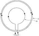
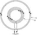
本発明によるRFIDリーダ用多重ループアンテナの具体的な例として、図1に示すように、一端が第1電源入力端子410に接続される1つ以上の直列巻線グループ100と、一端が直列巻線グループ410の他端に接続され、他端が第2電源入力端子420に接続される複数の並列巻線グループ210、220、…とを含むことができる。 As a specific example of a multiple loop antenna for an RFID reader according to the present invention, as shown in FIG. 1, one or more
前記直列巻線グループ100及び前記並列巻線グループ210、220、…は、設計条件などによって円形はもちろん四角形などの多様な形状に形成することができ、基板上にパターンをなして形成することもできる。 The
以下、本発明によるRFIDリーダ用多重ループアンテナについて実施例を挙げてより詳細に説明する。 Hereinafter, the multiple loop antenna for an RFID reader according to the present invention will be described in more detail with reference to examples.
実施例
本発明によるRFIDリーダ用多重ループアンテナは、少なくともN個(ここで、Nは3以上の整数であり、本実施例では3つである)の巻線グループ100、210、220が、V0の電圧を印加する第1電源入力端子410及び第2電源入力端子420を基準に互いに直並列に接続されている。EXAMPLE A multiple loop antenna for an RFID reader according to the present invention has at least
また、それぞれの巻線グループ100、210、220は、少なくとも1つの巻線が巻回されている。本実施例においては、直列巻線グループ100は1回、第1並列巻線グループ210は3回、第2並列巻線グループ220は2回巻回されているが、このような巻回数は使用目的によって変動することができる。 Each
また、本実施例においては、それぞれの巻線グループ100、210、220が円形状に巻回されているが、四角形や楕円形などの多様な形状に形成することができる。 In the present embodiment, each
一般に、2つのインダクタを直列に接続した場合、合成インダクタンスLstは、2つのインダクタンス値をそれぞれL1、L2とするとき、Lst=L1+L2に与えられ、2つのインダクタを並列に接続した場合、合成インダクタンスLptは、1/Lpt=1/L1+1/L2、すなわち、Lpt=(L1×L2)/(L1+L2)に与えられて、それぞれのインダクタンスL1、L2より小さい値となる。In general, when two inductors are connected in series, the combined inductance Lst is given to Lst = L1 + L2 when thetwo inductance values are L1 and L2 , respectively, and the two inductors are connected in parallel. In this case, the combined inductance Lpt is given by 1 / Lpt = 1 / L1 + 1 / L2 , that is, Lpt = (L1 × L2 ) / (L1 + L2 ). It becomes a value smaller than L1 and L2 .
巻線グループを直列に接続した場合と並列に接続した場合、各巻線グループが有するインダクタンスが、前述のようにインダクタを直列又は並列に接続した場合と類似した結果をもたらすものと考えることができる。ここで、アンテナのQに関連して考えてみると、全体のインダクタンスが大きくなるのはQが大きくなる方向である。 When the winding groups are connected in series and in parallel, the inductance of each winding group can be considered to bring about a result similar to the case where the inductors are connected in series or in parallel as described above. Here, when considering in relation to the Q of the antenna, the overall inductance increases in the direction of increasing Q.
図2に示す並列共振回路の場合、共振周波数とQ値が下記式に与えられ、全体のインダクタンスが大きくなる場合にQが大きくなることが分かる。 In the case of the parallel resonance circuit shown in FIG. 2, the resonance frequency and the Q value are given by the following equations, and it can be seen that Q increases when the overall inductance increases.

一方、Qが大きくなると使用帯域幅が狭くなる。従って、Qを適正な値以下に維持する必要がある。このような面で、巻線グループを直並列に接続することは、全体のインダクタンスの調節が可能であり、必要な帯域幅に合うようにQ値を調節するのに有利である。 On the other hand, as Q increases, the bandwidth used decreases. Therefore, it is necessary to maintain Q below an appropriate value. In this respect, connecting the winding groups in series and parallel allows adjustment of the overall inductance, and is advantageous for adjusting the Q value so as to match the required bandwidth.
一般に、インダクタンスは、巻線グループにおいて巻回数が多いほど大きくなり、また巻線長が長くなるほど大きくなる。直列給電の場合、各巻線グループの個別インダクタンスより合成インダクタンスを小さくすることができない反面、並列給電の場合は、合成インダクタンスが各巻線グループの個別インダクタンスより小さい。しかし、直並列巻線グループは、所望のインダクタンスに合うように値を調節できるので、Q値と帯域幅を容易に調節できる。 In general, the inductance increases as the number of turns in the winding group increases, and increases as the winding length increases. In the case of series feeding, the combined inductance cannot be made smaller than the individual inductance of each winding group. However, in the case of parallel feeding, the combined inductance is smaller than the individual inductance of each winding group. However, since the value of the series-parallel winding group can be adjusted to match a desired inductance, the Q value and the bandwidth can be easily adjusted.
また、直列給電の場合、各巻線グループが直列に接続されており、各巻線グループに流れる電流が同一であり、並列給電の場合、各巻線グループに流れる電流をそれぞれ個別に調節できるが、直並列給電は、これら2つの利点を全て有するので多様な設計が可能である。導線の周囲に形成される磁場の大きさは電流の強さに比例するので、結果的に、本発明によるRFIDリーダ用多重ループアンテナは、全体磁場を多様にすることができることが分かる。 In the case of series power supply, each winding group is connected in series, and the current flowing in each winding group is the same. In the case of parallel power supply, the current flowing in each winding group can be adjusted individually. Since the power supply has all these two advantages, various designs are possible. Since the magnitude of the magnetic field formed around the conducting wire is proportional to the current intensity, it can be seen that the multi-loop antenna for the RFID reader according to the present invention can diversify the entire magnetic field.
図1に示すように、内部に位置する直列巻線グループ100と単一ループの第1並列巻線グループ210、外部に位置する第2並列巻線グループ220は、同一方向に巻回されるようにして、直列巻線グループ100に直列に接続されている並列巻線グループである第1並列巻線グループ210で生成された磁場が、第2並列巻線グループ220で生成された磁場と合わせられるようにしなければならない。また、第2並列巻線グループ220の半径r1が直列巻線グループ100の半径r2より小さくないようにすることができ、RFIDリーダの認識可能面積を十分に確保することができる。 As shown in FIG. 1, the
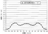
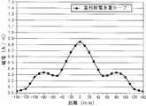
図3a〜図3cは、同一の電圧を印加した場合、それぞれのRFIDリーダ用多重ループアンテナの表面からの距離による磁場の強度(アンテナの表面に垂直な成分Hz)を示す図であり、図3aは図1に示す本発明によるRFIDリーダ用多重ループアンテナを、図3bは図5に示す従来のRFIDリーダ用多重ループアンテナを、図3cは図4に示す従来のRFIDリーダ用多重ループアンテナをそれぞれ示す。
3a to 3c are diagrams showing the strength of the magnetic field (component Hz perpendicular to the antenna surface) depending on the distance from the surface of the multiple loop antenna for each RFID reader when the same voltage is applied.1 shows a multiple loop antenna for an RFID reader according to the present invention shown inFIG. 1 , FIG. 3b shows a conventional multiple loop antenna for an RFID reader shown in FIG. 5, and FIG. 3cshows a conventional multiple loop antenna for an RFID reader shown in FIG. Show.
ここで、アンテナの外郭の大きさは同一であり、横軸は、巻線グループで形成されたアンテナを、多重巻線の中心を含んで切断した状態と理解することができ、縦軸は、アンテナの表面からの距離を示す。 Here, the size of the outline of the antenna is the same, and the horizontal axis can be understood as a state where the antenna formed by the winding group is cut including the center of the multiple winding, Indicates the distance from the surface of the antenna.
図3a〜図3cに示すように、Hzの最大値を見ると、並列巻線グループの場合が直列巻線グループの場合よりも大きく、本発明の直並列巻線グループの場合が並列巻線グループの場合よりも大きい。また、最大値から減衰していく形状を見ると、本発明の直並列巻線グループを備えたループアンテナの磁場強度のような磁界特性が、直列巻線グループを備えたループアンテナと並列巻線グループを備えたループアンテナに比べて優れている。さらに、直並列巻線グループの場合、ループアンテナの表面で中心部の磁界強度が最も大きい。 As shown in FIGS. 3a to 3c, when the maximum value of Hz is seen, the case of the parallel winding group is larger than the case of the series winding group, and the case of the series-parallel winding group of the present invention is the parallel winding group. Larger than the case. Further, when looking at the shape that attenuates from the maximum value, the magnetic field characteristics such as the magnetic field strength of the loop antenna having the series-parallel winding group of the present invention are similar to those of the loop antenna having the series winding group and the parallel winding. Compared to loop antennas with groups. Further, in the case of the series-parallel winding group, the magnetic field strength at the center is the largest on the surface of the loop antenna.
すなわち、本発明の直並列巻線グループは、並列巻線グループに比べて中心部の磁界強度が増加して、より長い認識可能距離を有する。 That is, the series-parallel winding group of the present invention has a longer recognizable distance because the magnetic field strength at the center portion is increased as compared with the parallel winding group.
以上、本発明の好ましい実施例を説明したが、本発明の範囲は、このような特定の実施例に限定されるものではなく、特許請求の範囲に記載されたカテゴリー内で適切に変更可能である。 Although the preferred embodiments of the present invention have been described above, the scope of the present invention is not limited to such specific embodiments, and can be appropriately changed within the categories described in the claims. is there.
100 直列巻線グループ
210 第1並列巻線グループ
220 第2並列巻線グループ
410 第1電源入力端子
420 第2電源入力端子100
Claims (8)
Translated fromJapanese1回以上巻回された3つ以上の巻線グループを含み、
前記各巻線グループ中の一つはその一端が第1電源入力端子に連結され、残りは前記第1電源入力端子に連結された巻線グループの他端と第2電源入力端子との間で並列に接続されていることを特徴とするRFIDリーダ用多重ループアンテナ。A RFID reader loop antenna for exchanging information with an RFID tag by electromagnetic induction,
Including three or more winding groups wound one or more times,
Theone ineach winding groupits one end connected to the first power supply input terminal, the remainder between the other end and the second power supply input terminal of the connected winding group to the first power supply input terminal A multi-loop antenna for an RFID reader, which is connected in parallel.
一端が第1電源入力端子に接続される第1巻線グループと、
一端が前記第1巻線グループの他端と、他端が第2電源入力端子と、の間で並列に連結される複数の第2巻線グループと、
を含むことを特徴とするRFIDリーダ用多重ループアンテナ。A RFID reader loop antenna for exchanging information with an RFID tag by electromagnetic induction,
Afirst winding group having one end connected to the first power input terminal;
And the other end is thefirst winding groupand the other end,and a second power supplyinput, and a plurality of thesecond winding groupwhich is connected in parallel between,
A multiple loop antenna for an RFID reader, comprising:
Applications Claiming Priority (1)
| Application Number | Priority Date | Filing Date | Title |
|---|---|---|---|
| KR20060130804 | 2006-12-20 |
Publications (2)
| Publication Number | Publication Date |
|---|---|
| JP2008160781A JP2008160781A (en) | 2008-07-10 |
| JP4452782B2true JP4452782B2 (en) | 2010-04-21 |
Family
ID=39541978
Family Applications (1)
| Application Number | Title | Priority Date | Filing Date |
|---|---|---|---|
| JP2007000548AExpired - Fee RelatedJP4452782B2 (en) | 2006-12-20 | 2007-01-05 | Multiple loop antenna for RFID reader, RFID reader having the same, and RFID system having the same |
Country Status (3)
| Country | Link |
|---|---|
| US (1) | US20080150693A1 (en) |
| JP (1) | JP4452782B2 (en) |
| KR (1) | KR100965494B1 (en) |
Families Citing this family (55)
| Publication number | Priority date | Publication date | Assignee | Title |
|---|---|---|---|---|
| US20090159682A1 (en)* | 2007-12-24 | 2009-06-25 | Dynamics Inc. | Cards and devices with multi-function magnetic emulators and methods for using same |
| JP5029371B2 (en)* | 2008-01-08 | 2012-09-19 | パナソニック株式会社 | Antenna device and adjustment method thereof |
| WO2010066955A1 (en) | 2008-12-11 | 2010-06-17 | Yves Eray | Rfid antenna circuit |
| KR101757615B1 (en)* | 2009-01-30 | 2017-07-26 | 도다 고교 가부시끼가이샤 | Magnetic antenna, rf tag, and substrate having the rf tag mounted thereon |
| US11476566B2 (en) | 2009-03-09 | 2022-10-18 | Nucurrent, Inc. | Multi-layer-multi-turn structure for high efficiency wireless communication |
| WO2011055702A1 (en)* | 2009-11-04 | 2011-05-12 | 株式会社村田製作所 | Wireless ic tag, reader/writer, and information processing system |
| US8508342B2 (en)* | 2009-11-19 | 2013-08-13 | Panasonic Corporation | Transmitting / receiving antenna and transmitter / receiver device using the same |
| US8390516B2 (en)* | 2009-11-23 | 2013-03-05 | Harris Corporation | Planar communications antenna having an epicyclic structure and isotropic radiation, and associated methods |
| KR101255485B1 (en)* | 2011-11-18 | 2013-04-16 | 한국과학기술원 | An antiparallel resonant loops and a resonant loops array using the antiparallel resonant loops |
| FR2987904B1 (en)* | 2012-03-07 | 2014-03-21 | Commissariat Energie Atomique | DEVICE FOR EVALUATING THE DISTANCE BETWEEN AN RFID LABEL AND AN INTERFACE |
| US9934895B2 (en)* | 2012-06-29 | 2018-04-03 | Intel Corporation | Spiral near field communication (NFC) coil for consistent coupling with different tags and devices |
| GB201212040D0 (en) | 2012-07-05 | 2012-08-22 | Cryogatt Systems Ltd | Box reader |
| KR20140051679A (en)* | 2012-10-23 | 2014-05-02 | 삼성전자주식회사 | Antenna apparatus for near field communication and portable terminal using the same |
| JP6463594B2 (en)* | 2013-03-08 | 2019-02-06 | ニューカレント インコーポレイテッドNuCurrent, Inc. | High efficiency multi-layer wire structure for wireless communication |
| US9293825B2 (en)* | 2013-03-15 | 2016-03-22 | Verifone, Inc. | Multi-loop antenna system for contactless applications |
| JP6030991B2 (en)* | 2013-04-17 | 2016-11-24 | 日本電信電話株式会社 | Reversed phase double loop antenna |
| DE102013109212B4 (en)* | 2013-08-26 | 2019-07-25 | Infineon Technologies Ag | RFID device, RFID reader, portion hot drink machine and system |
| DE102013112599A1 (en)* | 2013-11-15 | 2015-05-21 | Feig Electronic Gmbh | RFID antenna arrangement with at least one RFID antenna and method for determining a distance of at least two conductor loops of an RFID antenna of an RFID antenna arrangement |
| KR101595848B1 (en)* | 2014-07-30 | 2016-02-23 | 한국철도기술연구원 | Apparatus for detecting position of transponder |
| FR3030908B1 (en)* | 2014-12-18 | 2016-12-09 | Stmicroelectronics Rousset | ANTENNA FOR ELECTRONIC DEVICE |
| JP6428354B2 (en)* | 2015-02-19 | 2018-11-28 | 株式会社セガゲームス | Automatic mahjong table and gaming table |
| US10511191B2 (en)* | 2015-07-09 | 2019-12-17 | Qualcomm Incorporated | Apparatus and methods for wireless power transmitter coil configuration |
| US11205848B2 (en) | 2015-08-07 | 2021-12-21 | Nucurrent, Inc. | Method of providing a single structure multi mode antenna having a unitary body construction for wireless power transmission using magnetic field coupling |
| US9941729B2 (en) | 2015-08-07 | 2018-04-10 | Nucurrent, Inc. | Single layer multi mode antenna for wireless power transmission using magnetic field coupling |
| US9960629B2 (en) | 2015-08-07 | 2018-05-01 | Nucurrent, Inc. | Method of operating a single structure multi mode antenna for wireless power transmission using magnetic field coupling |
| US9948129B2 (en) | 2015-08-07 | 2018-04-17 | Nucurrent, Inc. | Single structure multi mode antenna for wireless power transmission using magnetic field coupling having an internal switch circuit |
| US10658847B2 (en) | 2015-08-07 | 2020-05-19 | Nucurrent, Inc. | Method of providing a single structure multi mode antenna for wireless power transmission using magnetic field coupling |
| US9941590B2 (en) | 2015-08-07 | 2018-04-10 | Nucurrent, Inc. | Single structure multi mode antenna for wireless power transmission using magnetic field coupling having magnetic shielding |
| US9960628B2 (en) | 2015-08-07 | 2018-05-01 | Nucurrent, Inc. | Single structure multi mode antenna having a single layer structure with coils on opposing sides for wireless power transmission using magnetic field coupling |
| US10636563B2 (en) | 2015-08-07 | 2020-04-28 | Nucurrent, Inc. | Method of fabricating a single structure multi mode antenna for wireless power transmission using magnetic field coupling |
| US9941743B2 (en) | 2015-08-07 | 2018-04-10 | Nucurrent, Inc. | Single structure multi mode antenna having a unitary body construction for wireless power transmission using magnetic field coupling |
| US10063100B2 (en) | 2015-08-07 | 2018-08-28 | Nucurrent, Inc. | Electrical system incorporating a single structure multimode antenna for wireless power transmission using magnetic field coupling |
| US10985465B2 (en) | 2015-08-19 | 2021-04-20 | Nucurrent, Inc. | Multi-mode wireless antenna configurations |
| JP6100945B1 (en)* | 2016-03-30 | 2017-03-22 | 株式会社バンダイ | Toy system and toy |
| US20180062434A1 (en) | 2016-08-26 | 2018-03-01 | Nucurrent, Inc. | Wireless Connector Receiver Module Circuit |
| US10432031B2 (en) | 2016-12-09 | 2019-10-01 | Nucurrent, Inc. | Antenna having a substrate configured to facilitate through-metal energy transfer via near field magnetic coupling |
| US11502547B2 (en) | 2017-02-13 | 2022-11-15 | Nucurrent, Inc. | Wireless electrical energy transmission system with transmitting antenna having magnetic field shielding panes |
| US11283295B2 (en) | 2017-05-26 | 2022-03-22 | Nucurrent, Inc. | Device orientation independent wireless transmission system |
| WO2020061382A1 (en) | 2018-09-19 | 2020-03-26 | The Trustees Of Columbia University In The City Of New York | Systems, methods, and media for multi-antenna, directional backscatter tags |
| EP3963659B1 (en) | 2019-05-28 | 2023-09-27 | Moog Inc. | Graduated frequency response non-contacting slip ring probe |
| US11227712B2 (en) | 2019-07-19 | 2022-01-18 | Nucurrent, Inc. | Preemptive thermal mitigation for wireless power systems |
| US11271430B2 (en) | 2019-07-19 | 2022-03-08 | Nucurrent, Inc. | Wireless power transfer system with extended wireless charging range |
| US11303011B2 (en) | 2019-11-27 | 2022-04-12 | AQ Corporation | Smartphone antenna in flexible PCB |
| WO2021138261A1 (en) | 2019-12-30 | 2021-07-08 | Avery Dennison Retail Information Services, Llc | Rfid tag antennas with multiple conductors |
| US11056922B1 (en) | 2020-01-03 | 2021-07-06 | Nucurrent, Inc. | Wireless power transfer system for simultaneous transfer to multiple devices |
| US11283303B2 (en) | 2020-07-24 | 2022-03-22 | Nucurrent, Inc. | Area-apportioned wireless power antenna for maximized charging volume |
| US11876386B2 (en) | 2020-12-22 | 2024-01-16 | Nucurrent, Inc. | Detection of foreign objects in large charging volume applications |
| US11881716B2 (en) | 2020-12-22 | 2024-01-23 | Nucurrent, Inc. | Ruggedized communication for wireless power systems in multi-device environments |
| US11695302B2 (en) | 2021-02-01 | 2023-07-04 | Nucurrent, Inc. | Segmented shielding for wide area wireless power transmitter |
| CN113054400A (en)* | 2021-03-23 | 2021-06-29 | 中国地质大学(武汉) | Omnidirectional RFID antenna device for controlling petroleum underground tool |
| US11831174B2 (en) | 2022-03-01 | 2023-11-28 | Nucurrent, Inc. | Cross talk and interference mitigation in dual wireless power transmitter |
| US12003116B2 (en) | 2022-03-01 | 2024-06-04 | Nucurrent, Inc. | Wireless power transfer system for simultaneous transfer to multiple devices with cross talk and interference mitigation |
| JP1783361S (en)* | 2024-02-19 | 2024-10-29 | Wireless communication tag | |
| USD1094344S1 (en)* | 2024-05-17 | 2025-09-23 | Avery Dennison Retail Information Services Llc | Antenna |
| USD1096704S1 (en)* | 2024-06-25 | 2025-10-07 | Avery Dennison Retail Information Services Llc | Antenna |
Family Cites Families (2)
| Publication number | Priority date | Publication date | Assignee | Title |
|---|---|---|---|---|
| KR20010044484A (en)* | 2001-02-26 | 2001-06-05 | 노명래 | Smart card |
| KR100604694B1 (en)* | 2004-05-27 | 2006-07-24 | (주)제이티 | Parallel Feed Multi-Loop Antennas for Wireless Readers |
- 2007
- 2007-01-05JPJP2007000548Apatent/JP4452782B2/ennot_activeExpired - Fee Related
- 2007-06-28USUS11/770,350patent/US20080150693A1/ennot_activeAbandoned
- 2007-11-30KRKR1020070123991Apatent/KR100965494B1/enactiveActive
Also Published As
| Publication number | Publication date |
|---|---|
| JP2008160781A (en) | 2008-07-10 |
| KR100965494B1 (en) | 2010-06-24 |
| KR20080058176A (en) | 2008-06-25 |
| US20080150693A1 (en) | 2008-06-26 |
Similar Documents
| Publication | Publication Date | Title |
|---|---|---|
| JP4452782B2 (en) | Multiple loop antenna for RFID reader, RFID reader having the same, and RFID system having the same | |
| US9024725B2 (en) | Communication terminal and information processing system | |
| CN102254212B (en) | Communication media, communication apparatus and antenna adjusting method | |
| US9461363B2 (en) | Communication terminal and information processing system | |
| JP2008167190A (en) | Base body sheet | |
| US7023391B2 (en) | Electromagnetic field generation antenna for a transponder | |
| KR101467706B1 (en) | The improved NFC antenna structure for reducing the proximity effect due to the coupled current loops | |
| CN107851900B (en) | Antenna device and module device | |
| US7438235B2 (en) | Non-contact information medium and communication system using non-contact information medium | |
| JP2007088661A (en) | Information processing apparatus and loop antenna | |
| CN102411720A (en) | Rfid antenna system | |
| JP4873158B2 (en) | RFID reader device | |
| KR100604694B1 (en) | Parallel Feed Multi-Loop Antennas for Wireless Readers | |
| KR101144490B1 (en) | Rf module for having tuning function | |
| US10990770B2 (en) | Portable object and NFC antenna thereof | |
| JP6511623B2 (en) | Auxiliary antenna and RFID system | |
| US9798969B2 (en) | Information processing device and communication device | |
| KR102563317B1 (en) | Anntena apparatus and portable electronic device including the same | |
| KR100924427B1 (en) | Antenna and rfid tag | |
| KR20160097839A (en) | Method Manufacturing of NFC Antenna Controlling Magnetic Field on Printed Circuit Board | |
| HK1246005A1 (en) | Antenna device and module device | |
| CN109994824A (en) | A kind of copper sheet extends out type around wire antenna and its application | |
| HK1222734B (en) | Information processing device and communication device |
Legal Events
| Date | Code | Title | Description |
|---|---|---|---|
| A977 | Report on retrieval | Free format text:JAPANESE INTERMEDIATE CODE: A971007 Effective date:20090327 | |
| A131 | Notification of reasons for refusal | Free format text:JAPANESE INTERMEDIATE CODE: A131 Effective date:20090526 | |
| A601 | Written request for extension of time | Free format text:JAPANESE INTERMEDIATE CODE: A601 Effective date:20090819 | |
| A602 | Written permission of extension of time | Free format text:JAPANESE INTERMEDIATE CODE: A602 Effective date:20090824 | |
| A601 | Written request for extension of time | Free format text:JAPANESE INTERMEDIATE CODE: A601 Effective date:20090924 | |
| A602 | Written permission of extension of time | Free format text:JAPANESE INTERMEDIATE CODE: A602 Effective date:20090929 | |
| A521 | Request for written amendment filed | Free format text:JAPANESE INTERMEDIATE CODE: A523 Effective date:20091026 | |
| TRDD | Decision of grant or rejection written | ||
| A01 | Written decision to grant a patent or to grant a registration (utility model) | Free format text:JAPANESE INTERMEDIATE CODE: A01 Effective date:20091117 | |
| A01 | Written decision to grant a patent or to grant a registration (utility model) | Free format text:JAPANESE INTERMEDIATE CODE: A01 | |
| A711 | Notification of change in applicant | Free format text:JAPANESE INTERMEDIATE CODE: A711 Effective date:20091216 | |
| A61 | First payment of annual fees (during grant procedure) | Free format text:JAPANESE INTERMEDIATE CODE: A61 Effective date:20091217 | |
| A521 | Request for written amendment filed | Free format text:JAPANESE INTERMEDIATE CODE: A821 Effective date:20091216 | |
| FPAY | Renewal fee payment (event date is renewal date of database) | Free format text:PAYMENT UNTIL: 20130212 Year of fee payment:3 | |
| R150 | Certificate of patent or registration of utility model | Ref document number:4452782 Country of ref document:JP Free format text:JAPANESE INTERMEDIATE CODE: R150 | |
| R250 | Receipt of annual fees | Free format text:JAPANESE INTERMEDIATE CODE: R250 | |
| R250 | Receipt of annual fees | Free format text:JAPANESE INTERMEDIATE CODE: R250 | |
| R250 | Receipt of annual fees | Free format text:JAPANESE INTERMEDIATE CODE: R250 | |
| R250 | Receipt of annual fees | Free format text:JAPANESE INTERMEDIATE CODE: R250 | |
| R250 | Receipt of annual fees | Free format text:JAPANESE INTERMEDIATE CODE: R250 | |
| R250 | Receipt of annual fees | Free format text:JAPANESE INTERMEDIATE CODE: R250 | |
| R250 | Receipt of annual fees | Free format text:JAPANESE INTERMEDIATE CODE: R250 | |
| R250 | Receipt of annual fees | Free format text:JAPANESE INTERMEDIATE CODE: R250 | |
| R250 | Receipt of annual fees | Free format text:JAPANESE INTERMEDIATE CODE: R250 | |
| LAPS | Cancellation because of no payment of annual fees |