JP4452279B2 - Drive source and transfer robot - Google Patents
Drive source and transfer robotDownload PDFInfo
- Publication number
- JP4452279B2 JP4452279B2JP2006529027AJP2006529027AJP4452279B2JP 4452279 B2JP4452279 B2JP 4452279B2JP 2006529027 AJP2006529027 AJP 2006529027AJP 2006529027 AJP2006529027 AJP 2006529027AJP 4452279 B2JP4452279 B2JP 4452279B2
- Authority
- JP
- Japan
- Prior art keywords
- drive source
- fixed shaft
- arm
- drive
- stator
- Prior art date
- Legal status (The legal status is an assumption and is not a legal conclusion. Google has not performed a legal analysis and makes no representation as to the accuracy of the status listed.)
- Expired - Lifetime
Links
Images


Classifications
- H—ELECTRICITY
- H01—ELECTRIC ELEMENTS
- H01L—SEMICONDUCTOR DEVICES NOT COVERED BY CLASS H10
- H01L21/00—Processes or apparatus adapted for the manufacture or treatment of semiconductor or solid state devices or of parts thereof
- H01L21/67—Apparatus specially adapted for handling semiconductor or electric solid state devices during manufacture or treatment thereof; Apparatus specially adapted for handling wafers during manufacture or treatment of semiconductor or electric solid state devices or components ; Apparatus not specifically provided for elsewhere
- H01L21/68—Apparatus specially adapted for handling semiconductor or electric solid state devices during manufacture or treatment thereof; Apparatus specially adapted for handling wafers during manufacture or treatment of semiconductor or electric solid state devices or components ; Apparatus not specifically provided for elsewhere for positioning, orientation or alignment
- H—ELECTRICITY
- H01—ELECTRIC ELEMENTS
- H01L—SEMICONDUCTOR DEVICES NOT COVERED BY CLASS H10
- H01L21/00—Processes or apparatus adapted for the manufacture or treatment of semiconductor or solid state devices or of parts thereof
- H01L21/67—Apparatus specially adapted for handling semiconductor or electric solid state devices during manufacture or treatment thereof; Apparatus specially adapted for handling wafers during manufacture or treatment of semiconductor or electric solid state devices or components ; Apparatus not specifically provided for elsewhere
- H01L21/677—Apparatus specially adapted for handling semiconductor or electric solid state devices during manufacture or treatment thereof; Apparatus specially adapted for handling wafers during manufacture or treatment of semiconductor or electric solid state devices or components ; Apparatus not specifically provided for elsewhere for conveying, e.g. between different workstations
- H01L21/67739—Apparatus specially adapted for handling semiconductor or electric solid state devices during manufacture or treatment thereof; Apparatus specially adapted for handling wafers during manufacture or treatment of semiconductor or electric solid state devices or components ; Apparatus not specifically provided for elsewhere for conveying, e.g. between different workstations into and out of processing chamber
- H01L21/67742—Mechanical parts of transfer devices
- B—PERFORMING OPERATIONS; TRANSPORTING
- B25—HAND TOOLS; PORTABLE POWER-DRIVEN TOOLS; MANIPULATORS
- B25J—MANIPULATORS; CHAMBERS PROVIDED WITH MANIPULATION DEVICES
- B25J19/00—Accessories fitted to manipulators, e.g. for monitoring, for viewing; Safety devices combined with or specially adapted for use in connection with manipulators
- B25J19/0075—Means for protecting the manipulator from its environment or vice versa
- B25J19/0079—Means for protecting the manipulator from its environment or vice versa using an internal pressure system
- B—PERFORMING OPERATIONS; TRANSPORTING
- B25—HAND TOOLS; PORTABLE POWER-DRIVEN TOOLS; MANIPULATORS
- B25J—MANIPULATORS; CHAMBERS PROVIDED WITH MANIPULATION DEVICES
- B25J9/00—Programme-controlled manipulators
- B25J9/06—Programme-controlled manipulators characterised by multi-articulated arms
- B—PERFORMING OPERATIONS; TRANSPORTING
- B25—HAND TOOLS; PORTABLE POWER-DRIVEN TOOLS; MANIPULATORS
- B25J—MANIPULATORS; CHAMBERS PROVIDED WITH MANIPULATION DEVICES
- B25J9/00—Programme-controlled manipulators
- B25J9/10—Programme-controlled manipulators characterised by positioning means for manipulator elements
- B25J9/106—Programme-controlled manipulators characterised by positioning means for manipulator elements with articulated links
- B25J9/1065—Programme-controlled manipulators characterised by positioning means for manipulator elements with articulated links with parallelograms
- B25J9/107—Programme-controlled manipulators characterised by positioning means for manipulator elements with articulated links with parallelograms of the froglegs type
- B—PERFORMING OPERATIONS; TRANSPORTING
- B25—HAND TOOLS; PORTABLE POWER-DRIVEN TOOLS; MANIPULATORS
- B25J—MANIPULATORS; CHAMBERS PROVIDED WITH MANIPULATION DEVICES
- B25J9/00—Programme-controlled manipulators
- B25J9/10—Programme-controlled manipulators characterised by positioning means for manipulator elements
- B25J9/12—Programme-controlled manipulators characterised by positioning means for manipulator elements electric
- B25J9/126—Rotary actuators
- B—PERFORMING OPERATIONS; TRANSPORTING
- B65—CONVEYING; PACKING; STORING; HANDLING THIN OR FILAMENTARY MATERIAL
- B65G—TRANSPORT OR STORAGE DEVICES, e.g. CONVEYORS FOR LOADING OR TIPPING, SHOP CONVEYOR SYSTEMS OR PNEUMATIC TUBE CONVEYORS
- B65G49/00—Conveying systems characterised by their application for specified purposes not otherwise provided for
- B65G49/05—Conveying systems characterised by their application for specified purposes not otherwise provided for for fragile or damageable materials or articles
- B65G49/06—Conveying systems characterised by their application for specified purposes not otherwise provided for for fragile or damageable materials or articles for fragile sheets, e.g. glass
- B65G49/067—Sheet handling, means, e.g. manipulators, devices for turning or tilting sheet glass
- B—PERFORMING OPERATIONS; TRANSPORTING
- B65—CONVEYING; PACKING; STORING; HANDLING THIN OR FILAMENTARY MATERIAL
- B65G—TRANSPORT OR STORAGE DEVICES, e.g. CONVEYORS FOR LOADING OR TIPPING, SHOP CONVEYOR SYSTEMS OR PNEUMATIC TUBE CONVEYORS
- B65G49/00—Conveying systems characterised by their application for specified purposes not otherwise provided for
- B65G49/05—Conveying systems characterised by their application for specified purposes not otherwise provided for for fragile or damageable materials or articles
- B65G49/07—Conveying systems characterised by their application for specified purposes not otherwise provided for for fragile or damageable materials or articles for semiconductor wafers Not used, see H01L21/677
- B—PERFORMING OPERATIONS; TRANSPORTING
- B65—CONVEYING; PACKING; STORING; HANDLING THIN OR FILAMENTARY MATERIAL
- B65G—TRANSPORT OR STORAGE DEVICES, e.g. CONVEYORS FOR LOADING OR TIPPING, SHOP CONVEYOR SYSTEMS OR PNEUMATIC TUBE CONVEYORS
- B65G2249/00—Aspects relating to conveying systems for the manufacture of fragile sheets
- B65G2249/02—Controlled or contamination-free environments or clean space conditions
- Y—GENERAL TAGGING OF NEW TECHNOLOGICAL DEVELOPMENTS; GENERAL TAGGING OF CROSS-SECTIONAL TECHNOLOGIES SPANNING OVER SEVERAL SECTIONS OF THE IPC; TECHNICAL SUBJECTS COVERED BY FORMER USPC CROSS-REFERENCE ART COLLECTIONS [XRACs] AND DIGESTS
- Y10—TECHNICAL SUBJECTS COVERED BY FORMER USPC
- Y10T—TECHNICAL SUBJECTS COVERED BY FORMER US CLASSIFICATION
- Y10T74/00—Machine element or mechanism
- Y10T74/20—Control lever and linkage systems
- Y10T74/20207—Multiple controlling elements for single controlled element
- Y10T74/20305—Robotic arm
- Y10T74/20317—Robotic arm including electric motor
- Y—GENERAL TAGGING OF NEW TECHNOLOGICAL DEVELOPMENTS; GENERAL TAGGING OF CROSS-SECTIONAL TECHNOLOGIES SPANNING OVER SEVERAL SECTIONS OF THE IPC; TECHNICAL SUBJECTS COVERED BY FORMER USPC CROSS-REFERENCE ART COLLECTIONS [XRACs] AND DIGESTS
- Y10—TECHNICAL SUBJECTS COVERED BY FORMER USPC
- Y10T—TECHNICAL SUBJECTS COVERED BY FORMER US CLASSIFICATION
- Y10T74/00—Machine element or mechanism
- Y10T74/20—Control lever and linkage systems
- Y10T74/20207—Multiple controlling elements for single controlled element
- Y10T74/20305—Robotic arm
- Y10T74/20329—Joint between elements
Landscapes
- Engineering & Computer Science (AREA)
- Robotics (AREA)
- Mechanical Engineering (AREA)
- Physics & Mathematics (AREA)
- Condensed Matter Physics & Semiconductors (AREA)
- General Physics & Mathematics (AREA)
- Manufacturing & Machinery (AREA)
- Computer Hardware Design (AREA)
- Microelectronics & Electronic Packaging (AREA)
- Power Engineering (AREA)
- Manipulator (AREA)
- Container, Conveyance, Adherence, Positioning, Of Wafer (AREA)
Description
Translated fromJapanese 本発明は、真空雰囲気で利用される駆動源および搬送ロボットに関する。より詳しくは、移動及び処理を行う際に高清浄な環境を必要とする環境と大気との境界に備えられる駆動源およびそれを備える基板等の搬送ロボットに関するものである。
なお、本発明は、移動及び処理を行う際に高い清浄環境を必要とする物品のいずれにも適用可能である。特に、以下の説明では電子部品である半導体ウエハや、LCDをあげて説明するが、これは例示のためであり、本発明を限定するものではない。The present invention relates to a drive source and a transfer robot used in a vacuum atmosphere. More specifically, the present invention relates to a drive source provided at the boundary between an environment that requires a highly clean environment when moving and processing and the atmosphere, and a transport robot such as a substrate provided with the drive source.
The present invention can be applied to any article that requires a high clean environment when moving and processing. In particular, in the following description, a semiconductor wafer and an LCD, which are electronic components, will be described. However, this is for illustrative purposes and does not limit the present invention.
一般に半導体やLCD等の基板の製造は高清浄な環境、いわゆるクリーンルームで行われる。このクリーンルーム内に備えられる半導体ウエハ等の製造装置は、多種多様の処理を行うために複数の処理装置を有する場合がある。このような処理装置では、製品の歩留まり(良品率)を高くするため、各種処理を行う処理室内を気密可能に閉鎖して、その内部を真空雰囲気にすることで、その内部をさらに高清浄に保ち、加工処理を行っている。さらに、各処理装置の処理室は、相互の装置の間で製品を移載するための移載室に連結され、移載室自身も気密に閉鎖可能である。また、移載室に搬送ロボットを備えることで、製造装置内に基板を搬出入するためのロードロック室から各処理室へ基板の移動を行うことができる。このような高真空の状況での製品の搬送を行うために、搬送装置の改良がなされている(特許文献1参照) In general, a substrate such as a semiconductor or an LCD is manufactured in a highly clean environment, a so-called clean room. A manufacturing apparatus for semiconductor wafers or the like provided in the clean room may have a plurality of processing apparatuses in order to perform a wide variety of processes. In such a processing apparatus, in order to increase the product yield (non-defective product rate), the processing chamber in which various processes are performed is closed in an airtight manner, and the inside is made a vacuum atmosphere, thereby further purifying the interior. Keeping and processing. Furthermore, the processing chamber of each processing apparatus is connected to a transfer chamber for transferring products between the apparatuses, and the transfer chamber itself can be closed in an airtight manner. Further, by providing a transfer robot in the transfer chamber, the substrate can be moved from the load lock chamber for loading / unloading the substrate into / from the manufacturing apparatus to each processing chamber. In order to carry the product in such a high vacuum, the carrying device has been improved (see Patent Document 1).
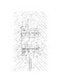
図10に示す搬送装置1Aは、クリーンルーム内の超真空環境であるマルチチャンバ内でウエハ等を搬送するものである。
搬送装置1Aは、真空チャンバ50(筐体)の壁体の一部に形成された開口部分に設置されている、搬送装置1Aは、フランジ部11(ベース部材)を有し、このフランジ部11と真空チャンバ50の壁体とは真空チャンバ50内の高真空に耐えられるように気密状態で取り付けられている。
フランジ部11には、真空チャンバ50の内部に向けて固定軸10(固定軸部材)が設置されている。固定軸10の外側には、中空構造の作動軸21、22(回動部材)が設置されている。作動軸21、22は、固定軸10と同軸状であるとともに、互いに上下方向にずらした位置に保持され、軸受けを介して回動自在に取り付けられている。
作動軸21、22の各々の内側において、固定軸10の外周には電磁式のステータS(電機子)が設置され、作動軸21、22の内周には永久磁石を用いたロータRが設置され、これらのステータSとロータRとは互いに対向した位置に配置され、これらにより電磁モータMが構成されている。ステータSは固定軸10に形成された凹部13に収容され、その外周(凹部13の開口面)には隔壁部材14が溶接され、これによりステータSを含む凹部13内と真空チャンバ50内とが隔絶されている。
作動軸21、22の各々の内側には、作動軸21、22の各々の位置検出のためにレゾルバ式の位置検出器40が設置されている。位置検出器40は、モータMとは固定軸10の軸方向にずれた領域に設置されている。位置検出器40は、モータMと同様にステータ42とロータ41とを有し、このうちステータ42はモータMと同様に固定軸10の凹部13内に収容され、外周を隔壁部材14で封止されている。
以上のフランジ部11ないし固定軸10、隔壁部材14、作動軸21,22、モータM、位置検出器40により高真空用の駆動源が構成されている。
ここで、作動軸21、22には搬送アームアッセンブリ30(駆動アーム)が接続されている。そして、作動軸21にはプーリー31が接続され、作動軸22にはアーム32が接続され、これらは搬送アームアッセンブリ30の先端に設置される可動機構(図示省略)を介して半導体ウエハ等の製品のハンドリングが行えるようになっている。
以上の搬送アームアッセンブリ30と駆動源とにより搬送装置1A(搬送ロボット)が構成されている。A transfer apparatus 1A shown in FIG. 10 transfers wafers and the like in a multi-chamber which is an ultra-vacuum environment in a clean room.
1 A of conveying apparatuses are installed in the opening part formed in a part of wall body of the vacuum chamber 50 (housing | casing), 1 A of conveying apparatuses have the flange part 11 (base member), This
A fixed shaft 10 (fixed shaft member) is installed on the
Inside each of the
A resolver
The
Here, a transport arm assembly 30 (drive arm) is connected to the
The transfer device 1A (transfer robot) is configured by the
前述の搬送装置1Aでは、作動軸21、22の各々に対応するモータMを軸方向に挟むように一対の軸受Bが配置される。このため、作動軸21、22の軸方向の長さは、モータMの軸方向長さと軸受Bの軸方向長さの和となる。このため、作動軸21、22の軸方向の長さが大きくなり、小型化にあたって問題となっていた。特に、作動軸21、22を軸方向に配列する際には、前述した軸方向の長さが更に問題となる。
更に、前述の搬送装置1Aでは、レゾルバ式位置検出器40により作動軸21、22の位置検出を行う。通常、レゾルバ式位置検出器40はステータSの影響を受けやすく、ステータSから軸方向に離れた位置に備える必要がある。このため、搬送装置1A全体の軸方向の大きさ(高さ)が更に大きくなるという問題がある。In the transfer device 1A described above, a pair of bearings B are arranged so as to sandwich the motor M corresponding to each of the
Further, in the above-described transport apparatus 1A, the position of the
前述の搬送装置1Aでは、固定軸10の凹部13にステータSを収容して、その外側に隔壁部材14を溶接して取り付ける。このため、隔壁部材の厚みが厚くなると、ステータSからロータRまでの間隔が広くなり、モータトルクが小さくなると共に停止位置の精度も低くなる。
更に、固定軸10と作動軸21、22とは軸受Bを介して取り付けられる。この際、作動軸21,22の回動による作動軸自身の撓みや振動等を考慮して、隔壁部材14からロータRまでの距離に余裕を設ける必要があり、この点でもモータトルクの減少および位置精度の低下が懸念される。In the transfer device 1A described above, the stator S is accommodated in the
Further, the
また、この搬送装置1Aでは、アーム32内部であって作動軸21に取り付けたプーリーの回動により、ベルトを介して搬送アームアッセンブリ130を動作させる。この搬送装置1Aのアーム32は真空雰囲気中にあり、アーム32内部と真空雰囲気とを遮断するための磁性シール等による発塵対策がなされていない。この搬送装置を超高真空(10−6Pa)かつ高温な環境において使用すれば、ベルト77内に含有する有機物等が揮発して真空チャンバ50内に舞って、汚染を引き起こして製品歩留まり(製品良品率)が悪くなる問題が生じる。Further, in the transfer apparatus 1A, the transfer arm assembly 130 is operated via the belt by the rotation of the pulley attached to the
本発明の駆動源は、筐体に設置されるベース部材と、前記ベース部材から前記筐体の内側に向けて設置された固定軸と、前記固定軸と同軸状に配置された回動部材と、前記前記固定軸を中心に前記回動部材を回転自在に支持する軸受と、前記固定軸と同軸状に配置された固定子と、前記回動部材に配置されかつ前記固定子に対向される回転子と、前記固定子と前記回転子との間に前記固定軸と同軸状に設置されて前記筐体外の大気雰囲気と前記筐体内の真空雰囲気とを隔てる隔壁部材と、を有し、前記固定軸の外側に前記固定軸と同軸状に設置されかつ前記固定軸に対して固定された円筒状の外周部材を有し、前記固定子は前記固定軸の外周または前記外周部材の内周の何れか一方に形成された凹部内に配置されかつ前記隔壁部材を挟んで前記回転子と互いに一定間隔で近接配置され、前記軸受は前記固定軸の外周または前記外周部材の内周の何れか他方に配置され、これらの固定子および軸受が前記固定軸の軸方向の同じ領域に同軸状に配置されていることを特徴とする。The drive source of the present invention includes a base member which is installed in a housing, a fixed shaft disposed toward the inside of said housing from said base member, a rotating member disposed onthe fixed shaft coaxially , is opposed tosaid bearingto said pivot member about a fixed shaft for rotatably supporting the arranged stator to said stationary shaft and coaxially disposed on the rotary member and the stator includes a rotor, and a partition member that separates the vacuum atmosphere in the enclosure and the atmosphere of the housing outer installed in the fixed shaft coaxially between said rotor and said stator,said A cylindrical outer peripheral member that is disposedcoaxially with the fixed shaft and fixed to the fixed shaft outside the fixed shaft; and the stator isarranged on an outer periphery of the fixed shaft or an inner periphery of the outer peripheral member.disposed either onewhich is formed in the recessand before sandwiching said partition member Rotor and disposed close at regular intervals from each other, wherein the bearing is arranged on the outer circumference or any other of the inner periphery of the outer peripheral member of the fixed shaft, the same region of the stator and bearing axial direction of the fixed shaft It is characterized by being arranged coaxially.
このような本発明の駆動源においては、モータを構成する固定子および回転子と、軸受とが、回動部材の回転軸の軸方向の同じ領域に同軸配置されることになり、駆動源としての軸方向長さを抑制することができる。このため、モータないし回動部材を軸方向に複数配置する場合でも、駆動源としての軸方向の寸法が大きくなることを防止できる。 In such a drive source of the present invention, the stator and rotor constituting the motor, and the bearing are coaxially arranged in the same region in the axial direction of the rotation shaft of the rotating member. The axial length can be suppressed. For this reason, even when a plurality of motors or rotating members are arranged in the axial direction, it is possible to prevent the axial dimension as a drive source from increasing.
本発明の駆動源において、前記ベース部材は前記筐体の開口部分に配置されており、前記外周部材と前記固定軸とはそれぞれ前記ベース部材の前記筐体内側に向かう同じ側に設置されている構成としてもよい。
このような構成とすれば、筐体の開口部分を封止することができ、筐体に設置する際に最も簡潔な構成とすることができる。In the drive source of the present invention, the base member is disposed in an opening portion of the casing, and the outer peripheral member and the fixed shaft are respectively installed on the same side of the base member toward the inner side of the casing. It is good also as a structure.
With such a configuration, the opening portion of the housing can be sealed, and the simplest configuration can be obtained when installing in the housing.
本発明の駆動源において、前記ベース部材は前記筐体の開口部分よりも前記筐体の外側に離れて配置されており、前記ベース部材と前記筐体とが前記外周部材で連結されている構成としてもよい。
このような構成とすれば、ベース部分が外周部材を介して支持され、駆動源を筐体の外側に張り出した形で設置することができる。これにより、筐体内の空間を駆動源が占有することを避けることができる。In the drive source according to the present invention, the base member is disposed farther outside the casing than the opening of the casing, and the base member and the casing are connected by the outer peripheral member. It is good.
With such a configuration, the base portion can be supported via the outer peripheral member, and the drive source can be installed in the form of projecting outside the housing. Thereby, it is possible to avoid the drive source from occupying the space in the housing.
本発明の駆動源において、前記ベース部材は前記筐体の開口部分よりも前記筐体の内側に離れて配置されており、前記ベース部材と前記筐体とが前記固定軸で連結されている構成としてもよい。
このような構成とすれば、ベース部分が固定軸を介して支持され、例えば可動部材ないしモータを二連構成とする場合に、筐体の開口部分から離れた側の構成として好適である。In the drive source of the present invention, the base member is disposed farther inside the casing than the opening of the casing, and the base member and the casing are connected by the fixed shaft. It is good.
With such a configuration, the base portion is supported via the fixed shaft, and is suitable as a configuration on the side away from the opening portion of the housing, for example, when the movable member or the motor has a dual configuration.
本発明の駆動源において、前記回動部材、前記回転子、前記固定子および前記軸受が、同じ固定軸の軸方向にずらした位置に複数組設置されている構成としてもよい。
このような構成によれば、例えばフロッグレッグ型の搬送ロボットのような二つの駆動が必要な場合でもコンパクトに対応できる。In the drive source of the present invention, a plurality of sets of the rotating member, the rotor, the stator, and the bearing may be installed at positions shifted in the axial direction of the same fixed shaft.
According to such a configuration, even when two drives such as a frog-leg type transfer robot are required, it is possible to deal with the compact.
前述した複数組を有する駆動源において、前記軸受の一つは前記回動部材の一つと前記固定軸とを回転自在に連結するとともに、前記軸受の他の一つは前記回動部材の一つを前記回動部材の他の一つに回転自在に連結することが望ましい。
このような構成によれば、各組の軸受を更に軸方向の同じ領域で重複させることができ、駆動源をよりコンパクトにすることができる。In the driving source having a plurality of sets described above, one of the bearings rotatably connects one of the rotating members and the fixed shaft, and the other one of the bearings is one of the rotating members. It is desirable to connect to the other one of the rotating members rotatably.
According to such a configuration, the bearings of each set can be further overlapped in the same region in the axial direction, and the drive source can be made more compact.
本発明の駆動源において、隔壁部材をはさんで対向する前記電機子と前記回動部材との間が一定距離であることが望ましい。
この一定距離は具体的に0.2mmから1.0mmであり、望ましくは0.2mmから0.5mmであり、さらに望ましくは0.2mmから0.3mmである。この一定距離が0.2mm以下であればさらに良いが、本発明においては回動部材が回転する際の偏芯量や、隔壁部材を真空雰囲気中においた際の微少な膨張(収縮)を考慮した結果0.2mm以上としている。例えば隔壁部材がステンレス鋼である場合、その厚みは0.05mmであっても十分に処理装置で処理を行うときの超高真空に耐えことができる。しかし、この駆動源を量産する際の個体差を考慮して前述の厚みに幅を持たせている。In the drive source of the present invention, it is desirable that a certain distance is provided between the armature and the rotating member facing each other with the partition member interposed therebetween.
This fixed distance is specifically 0.2 mm to 1.0 mm, desirably 0.2 mm to 0.5 mm, and more desirably 0.2 mm to 0.3 mm. The constant distance is preferably 0.2 mm or less, but in the present invention, the eccentric amount when the rotating member rotates and the slight expansion (contraction) when the partition member is placed in a vacuum atmosphere are considered. As a result, it is 0.2 mm or more. For example, when the partition member is stainless steel, even if the thickness is 0.05 mm, it can sufficiently withstand the ultra-high vacuum when the processing is performed by the processing apparatus. However, the above-mentioned thickness is widened in consideration of individual differences when mass-producing this drive source.
本発明の駆動源では、前記回動部材に磁石を備えることにより前記隔壁部材の内部に備える位置検出手段が回動部材の位置検出を行うようにしてもよい。
本発明の駆動源では、前記隔壁部材の素材がニッケル合金であることが望ましい。In the drive source according to the present invention, the rotating member may be provided with a magnet so that position detecting means provided inside the partition member may detect the position of the rotating member.
In the drive source of the present invention, it is desirable that the material of the partition member is a nickel alloy.
本発明の駆動源では、回動部材をベース部材上の隔壁部材とは異なる箇所に軸受け部材を介して備えてもよい。
このような構成により、回動部材を回動可能に支持するための剛性を必要としないため真空に耐えうるという条件のみを考慮した厚みにすることができる。また、隔壁部材に回動部材を備える場合に比べて、回動部材の回動により生じる撓みや振動による回動部材の偏芯量が減少する。これらの理由により、隔壁部材から回動部材までの距離を従来のものより狭くすることができる。In the drive source of the present invention, the rotating member may be provided at a location different from the partition member on the base member via a bearing member.
With such a configuration, it is not necessary to have rigidity for rotatably supporting the rotating member, so that the thickness can be set considering only the condition that it can withstand vacuum. Further, the amount of eccentricity of the rotating member due to bending or vibration caused by the rotation of the rotating member is reduced as compared with the case where the partition member includes the rotating member. For these reasons, the distance from the partition member to the rotating member can be made narrower than the conventional one.
本発明の隔壁部材は筒形状であり、且つ、その天井部は真空雰囲気と大気との圧力差に耐えることができるように、天井部の厚みが筒部分である側部に比べて厚い平板、若しくは、波形状等の板材でもよい。また、この隔壁部材の素材はステンレス鋼等の金属のみならず、透磁性の高い素材、例えばクリスタルガラス、ニッケル合金等を用いてもよい。 The partition wall member of the present invention has a cylindrical shape, and the ceiling part has a flat plate whose thickness is thicker than the side part which is a cylindrical part so that it can withstand the pressure difference between the vacuum atmosphere and the atmosphere, Alternatively, a plate material such as a wave shape may be used. The material of the partition member may be not only a metal such as stainless steel but also a material having high magnetic permeability, such as crystal glass or nickel alloy.
本発明の駆動源は、フロッグレッグ形状を有するリンク型ロボット等のスカラ型ロボットのいずれにも用いることができる。 The drive source of the present invention can be used for any SCARA robot such as a link robot having a frog leg shape.
本発明の搬送ロボットは、前述した本発明の駆動源と、駆動源に備える回動部材に突出して固設する駆動アームと、前記駆動アームの他端に回動可能に備える従動アームと、前記従動アームの他端に回動可能に備えるエンドエフェクタとからなる基板の搬送ロボットであって、前記電機子の作動により駆動アームが回動するとともに従動アームが連動することでエンドエフェクタを進退運動できることを特徴とする。 The transfer robot of the present invention includes the above-described drive source of the present invention, a drive arm that protrudes and is fixed to a rotation member provided in the drive source, a follower arm that is rotatably provided at the other end of the drive arm, A substrate transfer robot comprising a turnable end effector provided at the other end of the driven arm, wherein the drive arm is turned by the operation of the armature, and the end effector can be moved forward and backward by interlocking with the driven arm. It is characterized by.
本発明の搬送ロボットにおいて、前記回動部材の側面又は上面に2つの駆動アームを備えるとともに、該駆動アームの端部付近に従動アームをそれぞれ備えることで、2つのエンドエフェクタを進退運動することができる搬送ロボットであって、該エンドエフェクタの進退方向が同一または旋回方向にずれた方向であることが望ましい。 In the transport robot according to the present invention, the two end effectors can be moved forward and backward by providing two drive arms on the side surface or the upper surface of the rotating member and by providing a driven arm near the end of the drive arm. It is desirable that the transfer robot be capable of moving in the same direction or in a direction shifted in the turning direction.
本発明の搬送ロボットは、前述した本発明の駆動源と、駆動源に備える回動部材に突出して固設する第一駆動アームと、第一駆動アームと軸方向に異なる位置に回動中心を有する第二駆動アームと、第一駆動アーム、第二駆動アームと第一従動アーム、第二従動アームとを回動可能にそれぞれ支持するとともに、第一駆動アームの回動を第一従動アームへ伝達しかつ第二駆動アームの回動を第二従動アームへ伝達する回動伝達手段と、第一従動アームと第二従動アームに回動可能に支持されるエンドエフェクタと、を備える構成としてもよい。The transfer robot according to the present invention includes the above-described drive source according to the present invention, a first drive arm that protrudes and is fixed to a rotation member provided in the drive source, and a rotation center at a position different from the first drive arm in the axial direction. The second drive arm,the first drive arm, the second drive arm, the first driven arm, and the second driven arm are rotatably supported, and the first drivearm is turned to the first driven arm. A rotation transmitting meansfor transmitting and transmitting the rotation of the second drive arm to the second driven arm, and a first driven arm and an end effector supported rotatably on the second driven arm. Good.
以上のような本発明の駆動源は、隔壁を挟んで大気側に電機子を備えることで、塵埃の発生源を隔離することができる。また、隔壁の真空雰囲気側に回動部材を備えるとともに、この回動部材を回転可能に支持する軸受け部材を隔壁とは別の筺体内部に備える。これにより、回動部材を隔壁に回動可能に備える場合に比べて、回動部材の回動により発生する撓みや振動等を考慮しなくてもよくなり、隔壁から可動部材との間隔を狭くすることができ、隔壁に回動部材を支持するための剛性を持たせる必要がないので隔壁の厚みを従来のものより薄くすることができる。さらに、これにより電機子と回動部材とをより近づけることができて励磁力が増すとともに位置決め精度が高くすることがきる。 The drive source of the present invention as described above can isolate a dust generation source by providing an armature on the atmosphere side with a partition wall in between. In addition, a rotation member is provided on the vacuum atmosphere side of the partition wall, and a bearing member that rotatably supports the rotation member is provided in a housing separate from the partition wall. As a result, it is not necessary to consider the bending or vibration caused by the rotation of the rotation member, and the distance between the partition wall and the movable member is narrower than when the rotation member is provided in the partition wall so as to be rotatable. In addition, since it is not necessary to provide the partition with rigidity for supporting the rotating member, the thickness of the partition can be made thinner than the conventional one. Furthermore, this makes it possible to bring the armature and the rotating member closer, increasing the excitation force and increasing the positioning accuracy.
また、この駆動源では隔壁を固定軸部材や回動軸部材とは独立してベース部材に備えることから、超真空環境に耐えうる厚さであればよく、構造が簡素化できて真空雰囲気を保つことが容易になる。 Further, in this drive source, the partition wall is provided on the base member independently of the fixed shaft member and the rotating shaft member, so that the thickness may be sufficient to withstand the ultra-vacuum environment, the structure can be simplified, and the vacuum atmosphere Easy to keep.
本発明の駆動源では電機子とセンサとの間に磁性遮断手段を備えることで、センサの作動に影響を与えることなく電機子とセンサとの間隔を狭くすることができる。これにより駆動源全体高さを低くすることができ省スペース化することができる。 In the drive source of the present invention, by providing the magnetic shielding means between the armature and the sensor, the distance between the armature and the sensor can be narrowed without affecting the operation of the sensor. As a result, the overall height of the drive source can be reduced and space can be saved.
また、この駆動源を備える搬送ロボットでは塵埃の発生源であるベルト等を用いることなく、また駆動源の電機子やセンサ等を隔壁部材で隔離して発塵の発生を減少させることができる。 Further, in the transfer robot having the drive source, it is possible to reduce the generation of dust without using a belt or the like as a dust generation source, and by separating the armature or sensor of the drive source with a partition member.
1 駆動源
2 筐体
3 ベース部材
4 Oリング
5 隔壁部材
6,6a,6b 電機子(固定子)
7a〜7h センサ
8 固定軸部材
9,9a、9b 磁石(回転子)
10,10a、10b 回動部材
11,11a、11b 軸受け
12 搬送ロボット
13、13a、13b 駆動アーム
14、14a〜14d 従動アーム
15 エンドエフェクタ
16 基板
17a、17b 支軸
18 スチールベルト
19 回動伝達手段
20 筐体DESCRIPTION OF SYMBOLS 1
7a-7h Sensor 8
10, 10a,
〔第1実施形態〕
図1には、本発明の第1実施形態の駆動源1aが示されている。
駆動源1aは、内部を真空雰囲気とすることができる筐体2の開口部分に設置され、この筐体2内で製品搬送などを行う搬送ロボットを駆動する。
駆動源1aは、ベース部材3を有し、このベース部材3が前記筐体2の開口部分を覆うように固定されることで筺体2に取り付けられる。ベース部材3と筺体2の開口周縁との接触箇所には0リング4が設置され、互いの間は気密状態に維持される。ベース部材3の中央には筐体2の内部に延びる固定軸部材8が設置されている。固定軸部材8は中空であり、その内部空間はベース部材3と連通されている。但し、ベース部材3の同側には、固定軸部材8を覆う有底筒状の隔壁部材5が設置されている。この隔壁部材5により、筺体2の内部である真空領域IVと、筺体2の外側である大気領域IAとは、互いに気密状態に隔離されている。[First Embodiment]
FIG. 1 shows a drive source 1a according to the first embodiment of the present invention.
The drive source 1a is installed in an opening portion of the
The drive source 1 a has a
ベース部材3は図中下方に凸状に形成され、この立ち上がり部分(外周部材)が隔壁部材5と同軸に形成されている。この外周部材の内側には二列の軸受11が設置され、この軸受11を介して円筒状の回動部材10が回転自在に支持されている。回動部材10は、内周が隔壁部材5の外周に対して一定距離をおいて支持されている。
回動部材10の内周には、磁石9(回転子)およびセンサ7a、7bが同軸配置されている。固定軸部材8の外周には電機子6(固定子)およびセンサ7e、7fが同軸配置されている。磁石9および電機子6は隔壁部材5を挟んで対向配置され、センサ7a、7bおよびセンサ7e、7fも隔壁部材5を挟んで対向配置されている。これら対向配置された各々は、その先端が隔壁部材5に十分に近く配置され、互いに最小限の一定間隔で対向するように設定されている。
このような第1実施形態では、固定子である電機子6および回転子である磁石9に加え、軸受11までが固定軸部材8の軸方向の同じ領域に同軸状に配置されている。これにより、駆動源1aとしての軸方向の長さを短縮することが可能となる。The
A magnet 9 (rotor) and
In such a first embodiment, in addition to the armature 6 as a stator and the magnet 9 as a rotor, up to the
〔第2実施形態〕
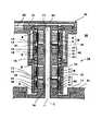
図2および図3には、一つの固定軸部材8に二つの回動部材10a、10bを高さ方向にずらして2つ設けた駆動源1bが示されている。
駆動源1bは、内部を真空雰囲気とすることができる筐体2に設置されている。ベース部材3およびその外周部材、隔壁部材5、固定軸部材8などの構成は前記第1実施形態と同様であるので重複する説明は省略する。
本実施形態においては、一つの固定軸部材8に二つの回動部材10a、10bが設置されている。このうち、一方の回動部材10aは、前記第1実施形態で述べたように、二列の軸受11aを介してベース部材3の外周部材に回転自在に支持されている。他方の回動部材10bは、二列の軸受11bを介して回動部材10aの上縁内側に回転自在に接続され、回動部材10aを介してベース部材3に支持されている。この構成では、ベース部材3と回動部材10aが回転自在であり、回動部材10a,10bが互いに回転自在であり、従って回動部材10a,10bは共にベース部材3に対してそれぞれ回転自在である。[Second Embodiment]
2 and 3 show a
The
In the present embodiment, two rotating
回動部材10aの内周には、センサ7e、7fおよび回転子である磁石9a、9bが設置されている。固定軸部材8の外周には、隔壁部材5を挟んで対向するセンサ7a、7bおよび固定子である電機子6a、6bが設置されている。これらの互いに対向する端部は、それぞれ隔壁部材5に近接され、僅かな一定間隔をおいて対向されている。
回動部材10bの内周には、センサ7g、7hおよび回転子である磁石9c、9dが設置されている。固定軸部材8の外周には、隔壁部材5を挟んで対向するセンサ7c、7dおよび固定子である電機子6c、6dが設置されている。これらの互いに対向する端部は、それぞれ隔壁部材5に近接され、僅かな一定間隔をおいて対向されている。
このような第2実施形態では、固定子である電機子6a,6bおよび回転子である磁石9a,9bに加え、軸受11a,11bまでが固定軸部材8の軸方向の同じ領域に同軸状に配置されている。これにより、駆動源1bとしての軸方向の長さを短縮することが可能となる。
In the second embodiment, in addition to the
なお、本実施形態の隔壁部材5は0.3mm程度の厚みを有する。これ半導体ウエハ等の処理を行うために高真空10−1Paから10−5Pa程度の真空状態や、超高真空10−6Paであっても変形や破損することなく動作できる程度の厚みである。In addition, the
本実施形態において、回動部材10a,10bに接続された搬送アームを備え、筐体2の内側において製品を搬送する搬送ロボット12aとして構成されている。
図4において、搬送ロボット12aは、基板16等を保持するエンドエフェクタの進退方向が旋回方向に異なる方向となるように備えるものである。この搬送ロボット12aは、駆動源1bの回動部材10a、10bの側面及び上面に駆動アーム13a、13bを水平面内へ突出して備える。この搬送ロボット12aでは、駆動源1の作動により駆動アーム13a、13bが回動して、駆動アーム13a、13bの端部上面に支承する従動アーム14a、14bが連動して、従動アーム14a、14bに回動可能に支持するエンドエフェクタ15を水平面内で進退運動することができる。In the present embodiment, a transport arm connected to the
In FIG. 4, the
また、この従動アーム14a、14b上に備えるエンドエフェクタ15を回動可能に支持する支軸17a、17bの側面に2本のスチールベルト18を高さ方向にずらして、S字状および逆S字状に巻き付けて備える。これによりエンドエフェクタ15に対して支軸17aと支軸18bとが互いに逆方向で同じ角度だけ回動することができる。この回動伝達手段は、後述する図7に示す回動伝達手段と同様の機構である。 Further, two
図4の搬送ロボット12aでは、駆動アーム13の端部上面に1つの従動アーム14をそれぞれ備えるものである。
これに対して図5に示す搬送ロボット12bは、駆動アーム13の端部上面に2つの従動アーム14a、14bをそれぞれ備える。この従動アーム14a、14bの端部付近にエンドエフェクタ15a、15bを備える。これにより180°異なる方向に進退運動でき、駆動源の作動により一方が進行すれば、他方が連動して後退して、基板の受け渡しを行うことができる。In the
In contrast, the
図6の搬送ロボット12cでは 図1の駆動源1aと、駆動源1aに備える回動部材10に突出して固設する駆動アーム13aと、駆動アーム13aと異なる位置に回動中心を有する駆動アーム13bと、駆動アーム13a、13bと従動アーム14a、14bとを回動可能にそれぞれ支持するとともに、駆動アーム13a、13bの回動を従動アーム14a、14bへ伝達する回動伝達手段19と、従動アーム14a、14bに回動可能に支持するエンドエフェクタ15とからなる搬送ロボットである。 In the
図7は図6の搬送ロボット12cの回動伝達手段19を示す一部切り欠き斜視図である。この回動伝達手段19は筐体20を有しており、この筐体20は駆動アーム13a、13bに備える支軸17aと従動アーム14a、14bに備える17bとを回動可能に支持する。この支軸17aと17bの側部には2本のスチールベルト18がS字状と逆S字状に巻き付けて備える。これにより駆動アーム13a、13bの回動を従動アーム14a、14bに伝達することができる。 FIG. 7 is a partially cutaway perspective view showing the rotation transmission means 19 of the
〔第3実施形態〕
図8には、一つの固定軸部材8に二つの回動部材10a、10bを高さ方向にずらして2つ設けた駆動源1cが示されている。
駆動源1cは、内部を真空雰囲気とすることができる筐体2に設置されている。ベース部材3およびその外周部材3a、隔壁部材5、固定軸部材8などの構成は前記第2実施形態と同様であるので重複する説明は省略する。なお、本実施形態においては、外周部材3aが軸方向に比較的長く形成され、二組の回動部材10a,10bの電機子6a,6b、磁石9a,9b部分は殆ど筐体2の外に配置されている。
本実施形態においては、固定軸部材8の外周には4列の軸受11aを介して回動部材10bが回転自在に支持され、その外側に2列の軸受11bを介して回動部材10aが回転自在に支持されている。これにより、回動部材10a,10bがそれぞれベース部材3に対して回転自在であることは前記第2実施形態と同様である。[Third Embodiment]
FIG. 8 shows a
The
In the present embodiment, a rotating
本実施形態においては、固定子である電機子6a,6bと、回転子である磁石9a,9bの内外が前記第2実施形態と逆になっている。
ベース部材3の外周部材3aの内周には凹部が形成され、その内部に電機子6a,6bが納められている。凹部の開口は隔壁部材5aで塞がれている。
回動部材10a,10bの外周には、電機子6a,6bと対向する磁石9a,9bが配置され、前記第2実施形態と同様、互いに一定間隔で近接配置されている。
なお、センサ7a〜7hに関しても、前記第2実施形態と逆の配置になっている。
このような第3実施形態でも、固定子である電機子6a,6bおよび回転子である磁石9a,9bに加え、軸受11a,11bまでが固定軸部材8の軸方向の同じ領域に同軸状に配置されている。これにより、駆動源1cとしての軸方向の長さを短縮することが可能となる。In this embodiment,
A recess is formed in the inner periphery of the outer
It should be noted that the
In the third embodiment as well, in addition to the
〔第4実施形態〕
図9には、一つの固定軸部材8に四つの回動部材10a〜10dを高さ方向にずらして2つ設けた駆動源1dが示されている。
駆動源1dは、内部を真空雰囲気とすることができる筐体2に設置されている。ベース部材3、隔壁部材5、固定軸部材8などの構成は前記第2実施形態と同様であるので重複する説明は省略する。
本実施形態においては、ベース部材3から筐体2の内側に向けて円筒状の外周部材3aが軸方向に立ち上がっている。また、固定軸部材8の先端には先端部材13が固定されている。先端部材13はベース部材3に相当する円盤状であり、その外周にはベース部材3に向かって立ち上がる外周部材13aが形成されている。[Fourth Embodiment]
FIG. 9 shows a driving
The
In the present embodiment, a cylindrical outer
外周部材3aの内周には2列の軸受11aを介して回動部材10aが回転自在に支持され、その内側には2列の軸受11bを介して回動部材10bが回転自在に支持されている。これにより、回動部材10a,10bがそれぞれベース部材3に対して回転自在である。
外周部材13aの内周には2列の軸受11cを介して回動部材10cが回転自在に支持され、その内側には2列の軸受11dを介して回動部材10dが回転自在に支持されている。これにより、回動部材10c,10dがそれぞれ先端部材13ないしベース部材3に対して回転自在である。A rotating
A rotating
各回動部材10a〜10dの内周には回転子である磁石9a〜9dが配置され、これらに対向して、固定軸部材8の外周には固定子である電機子6a〜6dが配置されている。これらの間には円筒状の隔壁部材5bが配置され、この隔壁部材5bを挟んで電機子6a〜6dと対向する磁石9a〜9dが互いに一定間隔で近接配置されている。
なお、各電機子6a〜6dおよび磁石9a〜9dに隣接して、センサ7a〜7pが配置されている。
このような第4実施形態でも、固定子である電機子6a〜6dおよび回転子である磁石9a〜9dに加え、軸受11a〜11dまでが固定軸部材8の軸方向の同じ領域に同軸状に配置されている。これにより、駆動源1dとしての軸方向の長さを短縮することが可能となる。
In the fourth embodiment as well, in addition to the
なお、本発明は前記各実施形態に限定されるものではなく、各実施形態における細部構造などは実施にあたって適宜設定可能である。
また、各実施形態における各機能部品は、それぞれ同様のもので代替するとしてもよく、例えば軸受はいわゆる転がり軸受に限らず、自己潤滑性の合成樹脂材料を用いたもの等であってもよい。更に、各部材の区画割りあるいは接合構造も適宜設計しうる事項であり、各部の材質等も必要条件に応じて適宜選択すればよい。Note that the present invention is not limited to the above-described embodiments, and the detailed structure in each embodiment can be appropriately set in the implementation.
In addition, each functional component in each embodiment may be replaced with the same one. For example, the bearing is not limited to a so-called rolling bearing, and may be one using a self-lubricating synthetic resin material. Furthermore, the partitioning or joining structure of each member is also a matter that can be designed as appropriate, and the material of each part may be appropriately selected according to the necessary conditions.
Claims (11)
Translated fromJapanese前記固定軸の外側に前記固定軸と同軸状に設置された円筒状の外周部材を有し、
前記固定子は前記固定軸の外周または前記外周部材の内周の何れか一方に形成された凹部内に配置されかつ前記隔壁部材を挟んで前記回転子と互いに一定間隔で近接配置され、
前記軸受は前記固定軸の外周または前記外周部材の内周の何れか他方に配置され、
これらの固定子および軸受が前記固定軸の軸方向の同じ領域に同軸状に配置されていることを特徴とする駆動源。The center and the base member which is installed in the housing, and a fixed shaft disposed toward the inside of said housing from said base member, a rotating member disposed on the fixed shaft coaxially,the fixed shaft a bearing for rotatably supportingthe rotating member, said fixed shaft and coaxially arranged stator, a rotor which is opposite to the disposed rotating member and the stator, and the stator A drive source having a partition member that is installed coaxially with the fixed shaft between the rotor and separates the air atmosphere outside the housing from the vacuum atmosphere inside the housing,
Acylindrical outer peripheral member installed coaxially with the fixed shaft outside the fixed shaft,
The stator is disposedin a recess formed on either the outer periphery of the fixed shaft or the inner periphery of the outer peripheral member,and is disposed close to the rotor at a constant interval across the partition member ,
The bearing is disposed on either the outer periphery of the fixed shaft or the inner periphery of the outer peripheral member,
A drive source characterized in that the stator and the bearing are coaxially arranged in the same region in the axial direction of the fixed shaft.
前記ベース部材は前記筐体の開口部分に配置されており、
前記外周部材と前記固定軸とはそれぞれ前記ベース部材の前記筐体内側に向かう同じ側に設置されていることを特徴とする駆動源。The drive source according to claim 1,
The base member is disposed in an opening of the housing;
The driving source according to claim 1, wherein the outer peripheral member and the fixed shaft are respectively installed on the same side of the base member toward the inner side of the casing.
前記ベース部材は前記筐体の開口部分よりも前記筐体の外側に離れて配置されており、
前記ベース部材と前記筐体とが前記外周部材で連結されていることを特徴とする駆動源。The drive source according to claim 1,
The base member is disposed farther outside the casing than the opening of the casing,
The drive source, wherein the base member and the casing are connected by the outer peripheral member.
前記ベース部材は前記筐体の開口部分よりも前記筐体の内側に離れて配置されており、
前記ベース部材と前記筐体とが前記固定軸で連結されていることを特徴とする駆動源。The drive source according to claim 1,
The base member is disposed farther inside the casing than the opening of the casing,
The drive source, wherein the base member and the casing are connected by the fixed shaft.
前記回動部材、前記回転子、前記固定子および前記軸受が、同じ固定軸の軸方向にずらした位置に複数組設置されていることを特徴とする駆動源。The drive source according to any one of claims 1 to 4,
A drive source characterized in that a plurality of sets of the rotating member, the rotor, the stator and the bearing are installed at positions shifted in the axial direction of the same fixed shaft.
前記軸受の一つは前記回動部材の一つと前記固定軸とを回転自在に連結するとともに、
前記軸受の他の一つは前記回動部材の一つを前記回動部材の他の一つに回転自在に連結することを特徴とする駆動源。The drive source according to claim 5,
One of the bearings rotatably connects one of the rotating members and the fixed shaft,
Another one of the bearings is characterized in that one of the rotating members is rotatably connected to the other one of the rotating members.
前記回動部材に磁石を備えることにより前記隔壁部材の内部に備える位置検出手段が回動部材の位置検出を行うことを特徴とする駆動源。The drive source according to any one of claims1 to 6 ,
A drive source characterized in that a position detecting means provided inside the partition wall member detects the position of the rotating member by providing the rotating member with a magnet.
前記隔壁部材の素材がニッケル合金であることを特徴とする駆動源。The drive source according to any one of claims1 to 7 ,
A drive source characterized in that a material of the partition member is a nickel alloy.
駆動源に備える回動部材に突出して固設する駆動アームと、
前記駆動アームの他端に回動自在に連結された従動アームと、
前記従動アームの他端に回動自在に連結されたエンドエフェクタとを有し、
前記駆動源により駆動アームが回動するとともに従動アームが連動することでエンドエフェクタを進退運動できることを特徴とする搬送ロボット。The drive source according to any one of claims1 to 8 ,
A drive arm that protrudes and is fixed to a rotating member provided in the drive source;
A follower arm rotatably connected to the other end of the drive arm;
An end effector coupled to the other end of the driven arm in a freely rotatable manner;
A transfer robot characterized in that a drive arm is rotated by the drive source and an end effector can move forward and backward by interlocking a driven arm.
前記回動部材の側面又は上面に2つの駆動アームを備えるとともに、各駆動アームの端部付近に連結された2つの従動アームと、各従動アームの端部付近に連結された2つのエンドエフェクタを有し、
該エンドエフェクタの進退方向が同一または旋回方向にずれた方向であることを特徴とする搬送ロボット。In the transfer robot according to claim9 ,
Two drive arms are provided on the side or upper surface of the rotating member, and two driven arms connected to the vicinity of the end of each drive arm, and two end effectors connected to the vicinity of the end of each driven arm. Have
A transfer robot characterized in that the advancing / retreating directions of the end effectors are the same or shifted in the turning direction.
駆動源に備える回動部材に突出して固設する第一駆動アームと、
第一駆動アームと軸方向に異なる位置に回動中心を有する第二駆動アームと、
第一駆動アーム、第二駆動アームと第一従動アーム、第二従動アームとを回動可能にそれぞれ支持するとともに、第一駆動アームの回動を第一従動アームへ伝達しかつ第二駆動アームの回動を第二従動アームへ伝達する回動伝達手段と、
第一従動アームと第二従動アームに回動可能に支持するエンドエフェクタと、
を備えることを特徴とする搬送ロボット。The drive source according to any one of claims1 to 8 ,
A first drive arm that protrudes and is fixed to a rotating member provided in the drive source;
A second drive arm having a rotation center at a position different from the first drive arm in theaxial direction ;
First drive arm, the second drive arm and the first driven arm, together with a second driven arm supports each rotatably, the rotation of the first drivearmand transmitted to the first driven armand the second drive arm Rotation transmitting meansfor transmitting the rotation of the second driven arm to the second driven arm ;
An end effector rotatably supported by the first driven arm and the second driven arm;
A transport robot comprising:
Applications Claiming Priority (3)
| Application Number | Priority Date | Filing Date | Title |
|---|---|---|---|
| JP2004203997 | 2004-07-09 | ||
| JP2004203997 | 2004-07-09 | ||
| PCT/JP2005/012746WO2006006554A1 (en) | 2004-07-09 | 2005-07-11 | Drive source and transportation robot |
Publications (2)
| Publication Number | Publication Date |
|---|---|
| JPWO2006006554A1 JPWO2006006554A1 (en) | 2008-04-24 |
| JP4452279B2true JP4452279B2 (en) | 2010-04-21 |
Family
ID=35783894
Family Applications (1)
| Application Number | Title | Priority Date | Filing Date |
|---|---|---|---|
| JP2006529027AExpired - LifetimeJP4452279B2 (en) | 2004-07-09 | 2005-07-11 | Drive source and transfer robot |
Country Status (6)
| Country | Link |
|---|---|
| US (1) | US7704036B2 (en) |
| JP (1) | JP4452279B2 (en) |
| KR (1) | KR100909993B1 (en) |
| CN (1) | CN1981371B (en) |
| DE (1) | DE112005001568T5 (en) |
| WO (1) | WO2006006554A1 (en) |
Families Citing this family (28)
| Publication number | Priority date | Publication date | Assignee | Title |
|---|---|---|---|---|
| US7891935B2 (en) | 2002-05-09 | 2011-02-22 | Brooks Automation, Inc. | Dual arm robot |
| US7946800B2 (en) | 2007-04-06 | 2011-05-24 | Brooks Automation, Inc. | Substrate transport apparatus with multiple independently movable articulated arms |
| US8267636B2 (en) | 2007-05-08 | 2012-09-18 | Brooks Automation, Inc. | Substrate transport apparatus |
| KR100980283B1 (en)* | 2008-02-12 | 2010-09-06 | 주식회사 뉴파워 프라즈마 | Substrate transfer device and substrate processing system having same |
| JP4770856B2 (en)* | 2008-03-21 | 2011-09-14 | トヨタ自動車株式会社 | Transfer robot |
| US8529136B2 (en)* | 2009-03-30 | 2013-09-10 | Wafertech, Llc | High temperature ball bearing |
| US10705692B2 (en) | 2009-05-21 | 2020-07-07 | Sony Interactive Entertainment Inc. | Continuous and dynamic scene decomposition for user interface |
| JP5810552B2 (en)* | 2011-02-25 | 2015-11-11 | 日本精工株式会社 | Motor rotation angle detection device and conveyance device |
| TWI691388B (en) | 2011-03-11 | 2020-04-21 | 美商布魯克斯自動機械公司 | Substrate processing tool |
| TWI587995B (en)* | 2011-07-13 | 2017-06-21 | 布魯克斯自動機械公司 | Compact direct drive spindle |
| US9186799B2 (en)* | 2011-07-13 | 2015-11-17 | Brooks Automation, Inc. | Compact direct drive spindle |
| KR102179267B1 (en) | 2011-09-16 | 2020-11-16 | 퍼시몬 테크놀로지스 코포레이션 | Robot Drive With Passive Rotor |
| KR20180128987A (en) | 2011-09-16 | 2018-12-04 | 퍼시몬 테크놀로지스 코포레이션 | An apparatus for moving substrates |
| US9202733B2 (en) | 2011-11-07 | 2015-12-01 | Persimmon Technologies Corporation | Robot system with independent arms |
| CN103192371B (en)* | 2012-01-06 | 2015-07-01 | 沈阳新松机器人自动化股份有限公司 | Spatial linkage type manipulator |
| JP2016537948A (en) | 2013-11-13 | 2016-12-01 | ブルックス オートメーション インコーポレイテッド | Sealed switched reluctance motor |
| TWI742414B (en)* | 2013-11-13 | 2021-10-11 | 美商布魯克斯自動機械公司 | Sealed switched reluctance motor |
| KR102224756B1 (en) | 2013-11-13 | 2021-03-08 | 브룩스 오토메이션 인코퍼레이티드 | Sealed robot drive |
| KR102383699B1 (en) | 2013-11-13 | 2022-04-06 | 브룩스 오토메이션 인코퍼레이티드 | Method and apparatus for brushless electrical machine control |
| TWI695447B (en) | 2013-11-13 | 2020-06-01 | 布魯克斯自動機械公司 | Transport apparatus |
| KR102432133B1 (en) | 2014-01-21 | 2022-08-12 | 퍼시몬 테크놀로지스 코포레이션 | Substrate transport vacuum platform |
| JP6378595B2 (en)* | 2014-09-19 | 2018-08-22 | 東京エレクトロン株式会社 | Substrate transfer device |
| US10515834B2 (en) | 2015-10-12 | 2019-12-24 | Lam Research Corporation | Multi-station tool with wafer transfer microclimate systems |
| US11312006B2 (en) | 2018-03-30 | 2022-04-26 | Fanuc Corporation | Robot drive unit and robot |
| JP6827437B2 (en)* | 2018-03-30 | 2021-02-10 | ファナック株式会社 | Drive unit for robot, robot and seal structure |
| CN115210046A (en)* | 2020-03-02 | 2022-10-18 | 柿子技术公司 | Compact type transverse moving robot |
| JP7504007B2 (en)* | 2020-11-24 | 2024-06-21 | ニデックインスツルメンツ株式会社 | Industrial Robots |
| CN118990464A (en)* | 2024-10-27 | 2024-11-22 | 苏州纳道精运半导体科技有限公司 | Outer rotor motor vacuum frog mobile robot |
Family Cites Families (10)
| Publication number | Priority date | Publication date | Assignee | Title |
|---|---|---|---|---|
| US4702668A (en)* | 1985-01-24 | 1987-10-27 | Adept Technology, Inc. | Direct drive robotic system |
| JPH04206543A (en) | 1990-11-30 | 1992-07-28 | Hitachi Ltd | Substrate transfer device for ultra-high vacuum equipment |
| CN1046654C (en) | 1993-04-16 | 1999-11-24 | 布鲁克斯自动化公司 | Articulated arm transfer device |
| JP3726978B2 (en) | 1996-10-28 | 2005-12-14 | 株式会社安川電機 | Articulated robot |
| JP3519595B2 (en)* | 1998-03-31 | 2004-04-19 | 松下電器産業株式会社 | Wafer transfer device |
| JP2000167792A (en)* | 1998-12-04 | 2000-06-20 | Daihen Corp | Transfer device |
| JP4206543B2 (en) | 1999-02-02 | 2009-01-14 | 株式会社デンソー | Semiconductor device |
| US6244811B1 (en)* | 1999-06-29 | 2001-06-12 | Lam Research Corporation | Atmospheric wafer transfer module with nest for wafer transport robot |
| TW473420B (en) | 1999-12-02 | 2002-01-21 | Komatsu Mfg Co Ltd | Robotic manipulator for conveyance |
| JP4227298B2 (en) | 1999-12-02 | 2009-02-18 | ローツェ株式会社 | Transfer robot |
- 2005
- 2005-07-11CNCN2005800228407Apatent/CN1981371B/ennot_activeExpired - Fee Related
- 2005-07-11JPJP2006529027Apatent/JP4452279B2/ennot_activeExpired - Lifetime
- 2005-07-11WOPCT/JP2005/012746patent/WO2006006554A1/enactiveApplication Filing
- 2005-07-11KRKR1020077000094Apatent/KR100909993B1/ennot_activeExpired - Fee Related
- 2005-07-11DEDE112005001568Tpatent/DE112005001568T5/ennot_activeWithdrawn
- 2005-07-11USUS11/631,679patent/US7704036B2/ennot_activeExpired - Fee Related
Also Published As
| Publication number | Publication date |
|---|---|
| US20080019816A1 (en) | 2008-01-24 |
| KR20070057758A (en) | 2007-06-07 |
| JPWO2006006554A1 (en) | 2008-04-24 |
| US7704036B2 (en) | 2010-04-27 |
| DE112005001568T5 (en) | 2007-08-23 |
| KR100909993B1 (en) | 2009-07-29 |
| CN1981371A (en) | 2007-06-13 |
| CN1981371B (en) | 2010-05-05 |
| WO2006006554A1 (en) | 2006-01-19 |
Similar Documents
| Publication | Publication Date | Title |
|---|---|---|
| JP4452279B2 (en) | Drive source and transfer robot | |
| US8008884B2 (en) | Substrate processing apparatus with motors integral to chamber walls | |
| US11772261B2 (en) | Compact direct drive spindle | |
| US9656386B2 (en) | Coaxial drive vacuum robot | |
| JP5627599B2 (en) | Transfer arm and transfer robot including the same | |
| KR20110052454A (en) | Arm mechanism and vacuum robot provided with the same | |
| WO2008059815A1 (en) | Rotation introducing mechanism, substrate transfer device, and vacuum treating apparatus | |
| JP4445075B2 (en) | Vacuum motor and transfer device | |
| TWI514499B (en) | Drive device and substrate processing system | |
| JP4106172B2 (en) | Transfer robot and vacuum chamber | |
| KR20230048598A (en) | Industrial robot | |
| JP2007019216A (en) | Substrate transfer robot | |
| JP2005236218A (en) | Semiconductor wafer transfer robot and processing apparatus including the same | |
| JPH06120320A (en) | Carrier | |
| WO2010146840A1 (en) | Substrate transfer device | |
| JP3672717B2 (en) | Sample transport device | |
| CN115924540A (en) | Industrial robot and manufacturing system | |
| JP2001347477A (en) | Transfer robot |
Legal Events
| Date | Code | Title | Description |
|---|---|---|---|
| A131 | Notification of reasons for refusal | Free format text:JAPANESE INTERMEDIATE CODE: A131 Effective date:20091110 | |
| A521 | Request for written amendment filed | Free format text:JAPANESE INTERMEDIATE CODE: A523 Effective date:20091228 | |
| TRDD | Decision of grant or rejection written | ||
| A01 | Written decision to grant a patent or to grant a registration (utility model) | Free format text:JAPANESE INTERMEDIATE CODE: A01 Effective date:20100126 | |
| A01 | Written decision to grant a patent or to grant a registration (utility model) | Free format text:JAPANESE INTERMEDIATE CODE: A01 | |
| A61 | First payment of annual fees (during grant procedure) | Free format text:JAPANESE INTERMEDIATE CODE: A61 Effective date:20100129 | |
| R150 | Certificate of patent or registration of utility model | Ref document number:4452279 Country of ref document:JP Free format text:JAPANESE INTERMEDIATE CODE: R150 Free format text:JAPANESE INTERMEDIATE CODE: R150 | |
| FPAY | Renewal fee payment (event date is renewal date of database) | Free format text:PAYMENT UNTIL: 20130205 Year of fee payment:3 | |
| FPAY | Renewal fee payment (event date is renewal date of database) | Free format text:PAYMENT UNTIL: 20130205 Year of fee payment:3 | |
| FPAY | Renewal fee payment (event date is renewal date of database) | Free format text:PAYMENT UNTIL: 20140205 Year of fee payment:4 | |
| R250 | Receipt of annual fees | Free format text:JAPANESE INTERMEDIATE CODE: R250 | |
| R250 | Receipt of annual fees | Free format text:JAPANESE INTERMEDIATE CODE: R250 | |
| R250 | Receipt of annual fees | Free format text:JAPANESE INTERMEDIATE CODE: R250 | |
| R250 | Receipt of annual fees | Free format text:JAPANESE INTERMEDIATE CODE: R250 | |
| R250 | Receipt of annual fees | Free format text:JAPANESE INTERMEDIATE CODE: R250 | |
| R250 | Receipt of annual fees | Free format text:JAPANESE INTERMEDIATE CODE: R250 | |
| R250 | Receipt of annual fees | Free format text:JAPANESE INTERMEDIATE CODE: R250 | |
| R250 | Receipt of annual fees | Free format text:JAPANESE INTERMEDIATE CODE: R250 | |
| R250 | Receipt of annual fees | Free format text:JAPANESE INTERMEDIATE CODE: R250 | |
| R250 | Receipt of annual fees | Free format text:JAPANESE INTERMEDIATE CODE: R250 | |
| R250 | Receipt of annual fees | Free format text:JAPANESE INTERMEDIATE CODE: R250 | |
| R250 | Receipt of annual fees | Free format text:JAPANESE INTERMEDIATE CODE: R250 | |
| EXPY | Cancellation because of completion of term |